US8825112B1 - Mobile communication device with electromagnetic radiation sensors - Google Patents
Mobile communication device with electromagnetic radiation sensorsDownload PDFInfo
- Publication number
- US8825112B1 US8825112B1US14/190,456US201414190456AUS8825112B1US 8825112 B1US8825112 B1US 8825112B1US 201414190456 AUS201414190456 AUS 201414190456AUS 8825112 B1US8825112 B1US 8825112B1
- Authority
- US
- United States
- Prior art keywords
- enabling
- sensor
- signal
- electromagnetic radiation
- temperature
- Prior art date
- Legal status (The legal status is an assumption and is not a legal conclusion. Google has not performed a legal analysis and makes no representation as to the accuracy of the status listed.)
- Expired - Fee Related
Links
Images


Classifications
- H—ELECTRICITY
- H04—ELECTRIC COMMUNICATION TECHNIQUE
- H04W—WIRELESS COMMUNICATION NETWORKS
- H04W88/00—Devices specially adapted for wireless communication networks, e.g. terminals, base stations or access point devices
- H04W88/02—Terminal devices
- H—ELECTRICITY
- H04—ELECTRIC COMMUNICATION TECHNIQUE
- H04B—TRANSMISSION
- H04B1/00—Details of transmission systems, not covered by a single one of groups H04B3/00 - H04B13/00; Details of transmission systems not characterised by the medium used for transmission
- H04B1/38—Transceivers, i.e. devices in which transmitter and receiver form a structural unit and in which at least one part is used for functions of transmitting and receiving
- H04B1/3827—Portable transceivers
- H04B1/3833—Hand-held transceivers
- H04B1/3838—Arrangements for reducing RF exposure to the user, e.g. by changing the shape of the transceiver while in use
- G—PHYSICS
- G01—MEASURING; TESTING
- G01J—MEASUREMENT OF INTENSITY, VELOCITY, SPECTRAL CONTENT, POLARISATION, PHASE OR PULSE CHARACTERISTICS OF INFRARED, VISIBLE OR ULTRAVIOLET LIGHT; COLORIMETRY; RADIATION PYROMETRY
- G01J1/00—Photometry, e.g. photographic exposure meter
- G01J1/42—Photometry, e.g. photographic exposure meter using electric radiation detectors
- G01J1/429—Photometry, e.g. photographic exposure meter using electric radiation detectors applied to measurement of ultraviolet light
- G—PHYSICS
- G01—MEASURING; TESTING
- G01J—MEASUREMENT OF INTENSITY, VELOCITY, SPECTRAL CONTENT, POLARISATION, PHASE OR PULSE CHARACTERISTICS OF INFRARED, VISIBLE OR ULTRAVIOLET LIGHT; COLORIMETRY; RADIATION PYROMETRY
- G01J5/00—Radiation pyrometry, e.g. infrared or optical thermometry
- G01J5/02—Constructional details
- G01J5/0265—Handheld, portable
- G—PHYSICS
- G01—MEASURING; TESTING
- G01J—MEASUREMENT OF INTENSITY, VELOCITY, SPECTRAL CONTENT, POLARISATION, PHASE OR PULSE CHARACTERISTICS OF INFRARED, VISIBLE OR ULTRAVIOLET LIGHT; COLORIMETRY; RADIATION PYROMETRY
- G01J5/00—Radiation pyrometry, e.g. infrared or optical thermometry
- G01J5/02—Constructional details
- G01J5/07—Arrangements for adjusting the solid angle of collected radiation, e.g. adjusting or orienting field of view, tracking position or encoding angular position
- G—PHYSICS
- G01—MEASURING; TESTING
- G01J—MEASUREMENT OF INTENSITY, VELOCITY, SPECTRAL CONTENT, POLARISATION, PHASE OR PULSE CHARACTERISTICS OF INFRARED, VISIBLE OR ULTRAVIOLET LIGHT; COLORIMETRY; RADIATION PYROMETRY
- G01J5/00—Radiation pyrometry, e.g. infrared or optical thermometry
- G01J5/02—Constructional details
- G01J5/08—Optical arrangements
- G01J5/0806—Focusing or collimating elements, e.g. lenses or concave mirrors
- G—PHYSICS
- G01—MEASURING; TESTING
- G01J—MEASUREMENT OF INTENSITY, VELOCITY, SPECTRAL CONTENT, POLARISATION, PHASE OR PULSE CHARACTERISTICS OF INFRARED, VISIBLE OR ULTRAVIOLET LIGHT; COLORIMETRY; RADIATION PYROMETRY
- G01J5/00—Radiation pyrometry, e.g. infrared or optical thermometry
- G01J5/10—Radiation pyrometry, e.g. infrared or optical thermometry using electric radiation detectors
- H—ELECTRICITY
- H04—ELECTRIC COMMUNICATION TECHNIQUE
- H04M—TELEPHONIC COMMUNICATION
- H04M1/00—Substation equipment, e.g. for use by subscribers
- H04M1/02—Constructional features of telephone sets
- H04M1/0202—Portable telephone sets, e.g. cordless phones, mobile phones or bar type handsets
- H04M1/026—Details of the structure or mounting of specific components
- H04M1/0264—Details of the structure or mounting of specific components for a camera module assembly
- G—PHYSICS
- G01—MEASURING; TESTING
- G01J—MEASUREMENT OF INTENSITY, VELOCITY, SPECTRAL CONTENT, POLARISATION, PHASE OR PULSE CHARACTERISTICS OF INFRARED, VISIBLE OR ULTRAVIOLET LIGHT; COLORIMETRY; RADIATION PYROMETRY
- G01J1/00—Photometry, e.g. photographic exposure meter
- G01J1/42—Photometry, e.g. photographic exposure meter using electric radiation detectors
- G01J2001/4266—Photometry, e.g. photographic exposure meter using electric radiation detectors for measuring solar light
- H—ELECTRICITY
- H04—ELECTRIC COMMUNICATION TECHNIQUE
- H04M—TELEPHONIC COMMUNICATION
- H04M1/00—Substation equipment, e.g. for use by subscribers
- H04M1/72—Mobile telephones; Cordless telephones, i.e. devices for establishing wireless links to base stations without route selection
- H04M1/724—User interfaces specially adapted for cordless or mobile telephones
- H04M1/72403—User interfaces specially adapted for cordless or mobile telephones with means for local support of applications that increase the functionality
- H—ELECTRICITY
- H04—ELECTRIC COMMUNICATION TECHNIQUE
- H04M—TELEPHONIC COMMUNICATION
- H04M2250/00—Details of telephonic subscriber devices
- H04M2250/12—Details of telephonic subscriber devices including a sensor for measuring a physical value, e.g. temperature or motion
- H—ELECTRICITY
- H04—ELECTRIC COMMUNICATION TECHNIQUE
- H04M—TELEPHONIC COMMUNICATION
- H04M2250/00—Details of telephonic subscriber devices
- H04M2250/52—Details of telephonic subscriber devices including functional features of a camera
Definitions
- the present inventionrelates generally to wireless communication devices. More specifically, this invention relates to mobile communication devices that incorporate additional sensors and detectors.
- wireless communication devicescellular or mobile telephones, e.g.
- additional non-communication featuressuch as imaging (photo and video), personal planners, games, etc.
- imagingphoto and video
- personal plannerssuch as personal planners
- gamesetc.
- inventionsthat attempt to include among these additional features the measurement and/or monitoring of external signals such as temperature. These inventions are exemplified by the following selection that is incorporated herein as references.
- Spectrum of the fieldmay be extremely broad ranging from constant levels of electric and magnetic fields to alternating EMF of very long wavelengths approximately from 6 ⁇ 106 m (corresponding to frequency of 50 Hz) to UV and further to X-rays.
- the present inventionrelates to three rather broad portions of the EMF spectrum.
- Oneis the portion having wavelengths from approximately 5 ⁇ 106 m to 2.5 cm, that is from very low frequency of 50 Hz to very high frequency of about 12 GHz that embrace EMRs emanated from high-voltage power lines, electric motors and generators, fluorescent lights, wireless routers and cellular telephones.
- EMFcreate the so-called low and radio-frequency EMF pollution that may have negative effects on humans and interfere with electronic equipment. Humans subjected to strong EMF may have increased risk of developing serious diseases, such as cancer, loss of reproductive functions, etc. Electronic equipment subjected to the interfering EMF may malfunction.
- thermometersoperate in this range.
- UVultraviolet
- a UV monitoringmay be useful for the health reasons to measure the level of personal exposure to sun radiation.
- the free-standing UV monitorsare known in art as exemplified by the U.S. Pat. No. 3,971,943 issued to Jeune Subscribe et al. that is incorporated herein as a reference.
- Thermal imaging camerasare exemplified by the U.S. Pat. No. 7,977,634 issued to Thiele et al. that is incorporated herein as a reference. Thermal images can be used in many applications, including medical (detection of subcutaneous inflammations, e.g.), scientific research, security, surveillance, etc.
- EMR measurement systemthat is subject of the present invention is used for monitoring the EMF pollution.
- the pervasive nature of EMF in modern life, and particularly in workplaces and at homecauses legitimate concerns about potential, particularly long term, health effects of EMR.
- Devices that emit this radiationinclude computers, computer terminals, computer tablets, cellular phones, routers, televisions, various Wi-Fi and Bluetooth devices.
- the exposure of children and young adults to mobile telephones and mobile electronic tabletsreached such a level that in several countries there is either adopted or proposed legislation limiting use of such devices by children.
- the ubiquitous nature of mobile communication devicesmakes them the most natural candidates for measuring the levels of ambient EMR.
- Patent Publication US 2010/0125438 issued to Audetincorporated here as a reference, teaches a method of measuring levels of EMF energy and storing a history of such measurements for each user with potential application to health care.
- An apparatus, system and a user graphical interfaceis taught, together with a communication system. Therefore this invention requires a special free-standing apparatus that may be expensive and inconvenient to carry around.
- U.S. Pat. No. 5,592,148 issued to Moralesteaches a ranging device that issues a warning output of the EMF signal generated by various devices.
- Most of the key components for reliable detection of a broad-band EMF signal by a free-standing apparatusare know in art as exemplified by the U.S. Pat. No. 6,906,663, issued to Johnston incorporated here as a reference, that teaches an antenna, power meter, signal equalizer and other components.
- a goal of the present inventionis to combine functionalities of the built-in digital photo camera, a non-contact thermometer and a pattern recognition algorithm for guiding the user for a proper positioning of the mobile communication device, thus insuring the optimal conditions for obtaining a reliable temperature measurement.
- Another goal of this inventionis to utilize the wireless capabilities of a mobile communication device for detecting and measuring the EMF signals for the purpose of assessing levels of ambient radiation.
- Another goal of this inventionis to integrate a UV detector with a mobile communication device. Further goals of the invention will be apparent from the foregoing description of preferred embodiments.
- a mobile communication deviceincorporates one or more sensing means for receiving and processing the EMF signals of different spectral ranges. Different spectral ranges require different types of sensors. For detecting the ambient electro-magnetic radiation pollution in a low and radio frequency ranges an antenna is employed, possibly the same antenna that is used for a mobile communication. For the UV range a special photo-diode is used, while for a non-contact temperature measurement the electro-magnetic radiation is detected by a thermopile. When the electro-magnetic radiation reaches a predetermined threshold, an alarm is generated to alert the user.
- a digital camera of the mobile phonecontinuously obtains images of the external object, such as a human face, processes the images for identifying facial landmarks and guides the user towards the optimal aim of the thermal radiation sensor at the pre-identified area of the face in relation to the landmarks.
- the obtained thermal signalis processed by the microprocessor (computer) for computation (determination), display and transmission of information, such as temperature, e.g.
- the digital cameramay function as a “viewfinder” for aiming the EMF detector.
- FIG. 1shows the back (left) and front (right) sides of a phone with an IR and video lenses.
- FIG. 2illustrates a cross-sectional view of the cell phone with an IR and video sensors.
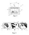
- FIG. 3shows a cross-sectional view of the thermal IR sensor.
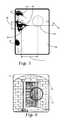
- FIG. 4shows three photographic images for three distances from the subject: too far (A), too close (B) and normal (C).
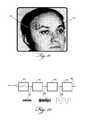
- FIG. 5illustrates positioning of IR sensor field of view over the subject's eye.
- FIG. 6shows part of a building with the field of view of a thermal IR sensor.
- FIG. 7illustrates the photographic image of the building structure with the temperature indication prepared for transmitting via the communication link.
- FIG. 8shows an image of the subject superimposed on an array thermal IR sensor fields of view.
- FIG. 9is a simplified block-diagram of a mobile telephone with IR sensor.
- FIG. 10depicts an algorithm for the digital image processing and landmark recognition.
- FIG. 11shows a target on the image of the subject.
- FIG. 12illustrates a block-diagram of the EMF detecting module.
- FIG. 13shows a multi-pixel thermal radiation sensor with a focusing lens.
- the central problem in non-contact temperature measurementis finding a location on the surface of the subject or object that is best suited for such measurement that is free from various obstructions and occlusions such as clothing, hair, decorations, etc.
- the non-contact IR sensorshould be positioned within a specific range of distances from the surface of the object where temperatures are measured. On the human face, these locations include the area of the temple within about 1 cm of the corner of the eye and the area of the forehead above the root of the nose between the eyes.
- the optimal range of distances between the surface of the skin and the IR sensoris between 2 and 10 cm.
- the present inventionutilizes the imaging capabilities of a camera-equipped communication device to assist in accurate positioning of the sensor embedded into the communication device.
- FIG. 1illustrates the back 3 and front 2 sides of the mobile communication device 1 .
- the lens 6 of the digital photographic camerais positioned alongside with the lens 7 of an IR sensor.
- the phone 1contains a display 4 and either hard or soft keys 5 positioned on the monitor 12 .
- the speaker 11can provide an audio feedback either by spoken voice or tone.
- the antenna 30(shown by a dotted line) typically is positioned inside the housing (enclosure) but in some cases may protrude outwardly (not shown).
- the mobile communication deviceamong other components incorporates a non-contact temperature module.
- the moduleincludes the infrared (IR) temperature detector, optical elements, reference temperature sensor and other relevant components known in art.
- FIG. 9is a block diagram of the wireless communication device that incorporates the present invention, specifically a non-contact IR thermometer.
- Power supply 27is a source of energy for all components of the device.
- the microprocessor 26controls all external components and performs necessary computation and image pattern recognition according to the algorithms described below.
- IR sensor 15is appended with a signal conditioning circuit 25 whose purpose is to match the sensor's, 15 , output signal format with the input format of the microprocessor 26 .
- Imaging sensor 16is part of the imaging circuit. Monitor 12 displays visual information, while the speaker 11 provides audible feedback.
- the wireless communication module 29that generally incorporates radio transmitter/receiver along with the antenna 30 performs wireless communication. Other essential components (like microphone, e.g.) that are part of the communication device but not required for functions of the current invention, are not shown for clarity.
- FIG. 2shows two sensors: the IR sensor 15 and the photo imaging digital sensor 16 positioned on the circuit board 14 inside the phone enclosure (housing, e.g.) 13 .
- the IR lens 7is situated substantially flash with the surface of the enclosure 13 .
- the angle of view 18 of the imaging sensor 16is much wider than the angle of view 17 of the IR sensor 15 .
- the field of view 70 of the IR sensor 15is much smaller than the field of view 71 of the imaging sensor 16 .
- the smaller field of view 70is part of the larger field of view 71 .
- the angle of view 18may be in the range of 90°, while the angle of view 17 is between 0 and 15°.
- FIG. 3illustrates a cross-sectional view of an IR sensor 15 . It incorporates a thermopile element 21 positioned inside the metal housing 19 .
- a reference temperature sensor 22monitors temperature of the substrate 20 .
- the angle of view 17is controlled by the IR focusing lens 7 that may be fabricated from silicon or germanium, preferably coated with the anti-reflective (AR) coating.
- the lens 7 focusing propertiesare achievable either by forming at least one convex surface or by etching into the lens the Fresnel grooves.
- An IR lens 7is fabricated of a material suitable for operating in the mid and far infrared spectral ranges. Suitable materials are silicon and germanium.
- a reflective focusing systemmay be employed instead of lens 7 .
- An example of suchis a curved (parabolic) mirror.
- the IR (thermal radiation) sensorsare also well known in art (see, for example, J. Fraden “ Handbook of modern sensors”, 4th ed, Springer Verlag, 2010, incorporated herein as a reference). To determine the object or subject surface temperature, the temperature is computed from signals generated by the IR sensing thermopile element 21 and ambient reference sensor 22 .
- images of the face of the subject of temperature measurementare taken by the communication device's camera as the operator (user) moves the camera towards the object's face and across the face.
- These imagescan be taken with a pre-defined frequency, e.g., 5 frames a second or 10 frames a second or any other frequency that insures that at least one image is obtained when the embedded infrared sensor is within 2-10 cm distance from the temple or forehead.
- a conventional IR sensorcontains a single sensitive pixel (thermopile 21 in FIG. 3 ) that collects IR signal from the surface whose optical image is formed by the multi-pixel photographic sensor 16 .
- the present inventionteaches how to achieve aiming of the IR temperature sensor at a correct location on the surface of the object together with an optimal distance between the sensor and the surface of the object at which the temperature should be taken. This can be accomplished by two methods that are described in detail below. One method is based on automated, computer assisted, guidance of the user aiming the IR temperature sensor and the other method is based on a manual guidance.
- FIG. 4shows the subject's face with the preferred IR spot 24 being located near the eye 23 .
- This spot 24is the area of the skin from which the IR signal should be collected for better accuracy of measurement.
- the eye 23has a distinct shape and its size varies only slightly over the human population.
- optical images of facial featuressuch as eye 23 can serve as “landmarks” that can guide the feedback system to help in correctly aiming the IR lens 7 toward the preferred location on the skin surface. Processing of the face image allows the measurements taken at the optimal range of distances from the skin.
- FIG. 4-Ashows an image of a human face taken from too large a distance for accurate measurement of the temperature due to interferences from the stray elements such as hair, clothing, decorations, etc. which enter the field of view 38 of the IR sensor.
- FIG. 4-Billustrates an image taken too close to the skin. While a very short distance under ideal conditions would not result in the increased measurement error, there is a possibility of touching the skin by the mobile communication device and thus cooling its surface. That may cause an excessively low temperature reading.
- FIG. 4-Cshows an image formed from an optimal distance to the skin surface where the IR field of view 38 covers substantially the preferred IR spot 24 with minimal inclusion of stray elements.
- the photo image from the digital image sensorprovides the necessary pattern recognition features to determine both the optimal superposition of the IR field of view 38 on the face image 35 ( FIG. 5 ), and the correct distance from the IR sensor to the skin.
- FIG. 5illustrates the correct size 39 of the eye 36 in the image, while dimensions 40 and 41 designate the distances from the center of the IR field of view 38 to the eye 36 .
- a key component of the present inventionis the combined use of both the IR and the photo sensors in a manner that assures that the IR measuring location is automatically found by the system from the optical images of the subject's face. This assisted guidance is especially beneficial when the user takes temperature of herself due to her limited ability to observe the display 4 ( FIG. 1 ), and is accomplished by finding landmarks on the human face that can be used for automated guidance of the IR sensor.
- Locating features (“landmarks” in our terminology herein) present in the images of human facescan be accomplished by various methods known in art, e.g.: www.cs.princeton.edu/courses/archive/fall08/cos436/FinalReports/Eye_Gesture_Recognition.pdf. incorporated as a reference herein.
- FIG. 10illustrates a basic flowchart of a recognition algorithm for landmarks such as eyebrows or eyelids.
- the image pre-processing stepthe image is first run through an edge detector such as Canny edge detector (Canny J., “Finding Edges and Lines in Images”, MIT AI Laboratory Technical Report, 720, June, 1983 incorporated here as a reference), resulting in a binary image. ( FIG. 10 , step 53 ). Once this pre-processed image is obtained, the system searches for certain landmarks in this image.
- an edge detectorsuch as Canny edge detector (Canny J., “Finding Edges and Lines in Images”, MIT AI Laboratory Technical Report, 720, June, 1983 incorporated here as a reference)
- these landmarkscould be certain facial features such as the eyebrows, the iris with the pupil of both eyes, or the eyelids of the subject.
- the eyelids, the iris with the pupil and the eyebrowsare sought for one eye.
- a profile image of the faceonly a partial view of facial features is available the fact that suits the template matching approach.
- the described facial landmarkscan be approximated by elliptical templates with variable major and minor axes since these landmarks have the shapes of partial ellipses.
- the ranges of axes lengthsare found from the size of the corresponding facial features and the resolution of the camera FIG. 10 , Step 55 .
- the use of elliptic templates of elastic shapeis illustrated in FIG. 10 , step 57 .
- the template matching via cross-correlation with an elliptic template with axes of varying sizeslocates the partial eyebrows and the contour of the eye (upper and lower eyelids) as depicted in FIG. 10 , step 57 , since coordinates of these landmarks are local maxima of the cross-correlation function (see D. A. Pintsov, as above).
- the parameters of this templateare restricted to the admissible range of sizes commensurate with the range of sizes of the corresponding facial features.
- it is desirable to locate more than one featureboth the eyebrow and the contour of the eye).
- step 63the system accepts the found features (leading to step 63 in FIG. 10 ), otherwise the landmarks are not found and the input image of the face is rejected ( FIG. 10 , step 61 ). Finally, as in step 63 , FIG. 10 , the calculated positions of the eyebrow and the eyelids must be consistent since the eyebrow must be located above the eye, which the system verifies.
- Partial ellipses 60 and 50 found by the template matching algorithmare shown in FIG. 5 superimposed on the actual contours of the eyebrow 37 and the eye 36 , respectively. Use of more than one ellipse increases reliability of the recognition.
- the size of the detected facial featurespermits finding the optimal distance to the object for a more accurate temperature measurement.
- the detected feature sizeis smaller than the appropriate size of the image of a facial feature under known camera resolution, the distance is too large.
- the distanceis too short.
- the detected and the expected sizesare close to one another, the distance is nearly optimal.
- FIG. 6illustrates a building door where the IR field of view 33 is superimposed on the area of interest whose temperature is to be measured.
- the resulting photo imagecan be combined with the computed temperature 34 ( FIG. 7 ) for wireless transmission over the communication line to a remote location.
- the methods for calculating temperatures of human body and of non-metallic surfaces of inanimate objectsare different and well known in the art and thus can be employed in the corresponding operating modes of the device. To switch between the human and non-human operating modes, a keyboard 5 can be used.
- voice or image guidance from the device's output componentsassists the user in positioning the device for taking accurate temperature measurements. This assistance instructs the user how to move the mobile communication device: closer, further, left, right, up, down, etc.
- a temperature readingis automatically taken, surface temperature is computed and shown on display 4 , or spoken via the speaker 11 ( FIG. 1 ), or transmitted by the wireless communication module 29 ( FIG. 9 ).
- thermopile 21( FIG. 3 ) can be divided into a plurality of areas (IR pixels) that will generate signals corresponding to adjacent locations on the measured surface.
- FIG. 13shows a metal header 90 that carries a substrate 91 supporting a membrane 92 .
- Multiple thermal sensitive pixels 93are positioned on the membrane 92 and respond to thermal infrared beam 96 that is focused by the optical element (a lens, e.g.) 95 on each individual pixel. Signals from multiple pixels create a thermal image of the object's surface.
- FIG. 13shows a metal header 90 that carries a substrate 91 supporting a membrane 92 .
- Multiple thermal sensitive pixels 93are positioned on the membrane 92 and respond to thermal infrared beam 96 that is focused by the optical element (a lens, e.g.) 95 on each individual pixel.
- a lense.g.
- FIG. 8illustrates a multi-pixel IR image with the individual pixels 42 (total 12 in this example) that are superimposed onto the image of the subject's face.
- the landmarkan eye 36 , e.g.
- signals from the superimposing IR pixels 43will be used for measuring and computing temperature.
- Other spurious pixels 37that are either at a wrong location or containing obstructions, such as an eyebrow or part of nose, are excluded from computation.
- the device's displayhas a designated area that is demarcated by a special graphical element.
- This elementis a circular or rectangular target 74 illustrated in FIG. 11 . Other shapes may be employed.
- the target 74substantially coincides with the IR sensor's field of view 70 ( FIG. 2 ) and thus the display serves as a viewfinder.
- the operatormanually aims the device at the object (e.g. at the head 73 ).
- the IR sensorin terms of a location and distance is properly positioned for taking the temperature measurement.
- the net resultis the same as with the computer-assisted method of aiming the IR lens at the optimal position 38 ( FIG. 5 ) of the IR field of view, for example, on the subject temple.
- Yet another feature of the present inventionlies in the ability of the microprocessor to record and store the temperature measurements over a desired period of time and transmit via communication abilities of the device any desired data to a medical facility or personnel. This assembly of data can be plotted on the display in form of a time chart. If the communication device is equipped with a Global Positioning System (GPS) another advantage the present invention derives from using this GPS is locating the nearest to the user pharmacy and directing the user to this pharmacy to obtain the necessary drug if the temperature level warrants such an action, that is when the measured temperature exceeds a pre-defined threshold stored in the computational means.
- GPSGlobal Positioning System
- a thermal image formed by a multi-pixel thermal radiation sensorcan be processed by the processor 26 and sent to display 4 as a black-and-white or false colors image representing temperature distribution within the field of view 70 .
- the mobile communication devicefunctions as a thermal imaging camera.
- a heade.g., the inner body temperature can be computed from the skin temperature by employing one of known in the art algorithms.
- a personal UV monitormay be useful for managing exposure to sun, for example for beach goers.
- a separate sensor sensitive in the rangecan be installed into the mobile communication device, however, its location with respect to the photographic camera is not as critical as for the IR sensor. It is important that the sensor's window can be exposed to the outside.
- This windowshould be fabricated from a material substantially transparent in the UV spectral range. Examples of the window materials are compressed inorganic salts of alkaline earth metals, such as KBr.
- the UV sensor in effectis a photo-detector whose sensitivity in enhanced in the UV region.
- a signal received from the UV sensorshould be digitized, its magnitude computed and integrated over a predetermined time by the microprocessor 26 .
- FIG. 9shows the following components used for detecting EMF: the antenna switch 81 and the EMF power measurement module 82 , both being controlled by the microprocessor 26 which is a computational means.
- the mobile communication deviceis not in a signal transmission state and antenna 30 doesn't radiate, it can be used for a broadband reception of external LF and RF EMF signals.
- switch 81On command from microprocessor 26 , switch 81 directs receiving EMF signals to the power measurement module 82 that feeds microprocessor 26 with a digital signal representing the EMF magnitude in vicinity of antenna 30 .
- the microprocessorcompares the magnitude with a pre-determined threshold and if the magnitude exceeds such a threshold, an alarm is optionally generated by an output device. Examples of such a device are the speaker 11 and vibrator 80 .
- a visual display(monitor 12 ) can show a numerical value of the EMF magnitude.
- FIG. 12illustrates structure of the power measurement module 82 that receives RF signal from antenna via the switch 81 .
- This signalis generally very weak and may have shape either of continuous or pulsed noise-like voltage 87 , or, alternatively a more specific shape, like a 60 Hz sine wave, e.g.
- Amplifier 83brings the received signal to a higher level 88 suitable for filtering and rectification by a signal conditioner 84 .
- the analog signal 89is fed to the analog-to-digital converter 85 that outputs digital stream 86 for further processing by the microprocessor 26 .
Landscapes
- Physics & Mathematics (AREA)
- General Physics & Mathematics (AREA)
- Spectroscopy & Molecular Physics (AREA)
- Engineering & Computer Science (AREA)
- Signal Processing (AREA)
- Computer Networks & Wireless Communication (AREA)
- Radiation Pyrometers (AREA)
Abstract
Description
Claims (13)
Priority Applications (1)
| Application Number | Priority Date | Filing Date | Title |
|---|---|---|---|
| US14/190,456US8825112B1 (en) | 2014-02-26 | 2014-02-26 | Mobile communication device with electromagnetic radiation sensors |
Applications Claiming Priority (1)
| Application Number | Priority Date | Filing Date | Title |
|---|---|---|---|
| US14/190,456US8825112B1 (en) | 2014-02-26 | 2014-02-26 | Mobile communication device with electromagnetic radiation sensors |
Publications (1)
| Publication Number | Publication Date |
|---|---|
| US8825112B1true US8825112B1 (en) | 2014-09-02 |
Family
ID=51400068
Family Applications (1)
| Application Number | Title | Priority Date | Filing Date |
|---|---|---|---|
| US14/190,456Expired - Fee RelatedUS8825112B1 (en) | 2014-02-26 | 2014-02-26 | Mobile communication device with electromagnetic radiation sensors |
Country Status (1)
| Country | Link |
|---|---|
| US (1) | US8825112B1 (en) |
Cited By (44)
| Publication number | Priority date | Publication date | Assignee | Title |
|---|---|---|---|---|
| US9058653B1 (en) | 2011-06-10 | 2015-06-16 | Flir Systems, Inc. | Alignment of visible light sources based on thermal images |
| US9208542B2 (en) | 2009-03-02 | 2015-12-08 | Flir Systems, Inc. | Pixel-wise noise reduction in thermal images |
| US9207708B2 (en) | 2010-04-23 | 2015-12-08 | Flir Systems, Inc. | Abnormal clock rate detection in imaging sensor arrays |
| US9235876B2 (en) | 2009-03-02 | 2016-01-12 | Flir Systems, Inc. | Row and column noise reduction in thermal images |
| US9292909B2 (en) | 2009-06-03 | 2016-03-22 | Flir Systems, Inc. | Selective image correction for infrared imaging devices |
| US9451183B2 (en) | 2009-03-02 | 2016-09-20 | Flir Systems, Inc. | Time spaced infrared image enhancement |
| US9473681B2 (en) | 2011-06-10 | 2016-10-18 | Flir Systems, Inc. | Infrared camera system housing with metalized surface |
| US9509924B2 (en) | 2011-06-10 | 2016-11-29 | Flir Systems, Inc. | Wearable apparatus with integrated infrared imaging module |
| US9517679B2 (en) | 2009-03-02 | 2016-12-13 | Flir Systems, Inc. | Systems and methods for monitoring vehicle occupants |
| US9635285B2 (en) | 2009-03-02 | 2017-04-25 | Flir Systems, Inc. | Infrared imaging enhancement with fusion |
| US9674458B2 (en) | 2009-06-03 | 2017-06-06 | Flir Systems, Inc. | Smart surveillance camera systems and methods |
| US9706137B2 (en) | 2011-06-10 | 2017-07-11 | Flir Systems, Inc. | Electrical cabinet infrared monitor |
| US9706139B2 (en) | 2011-06-10 | 2017-07-11 | Flir Systems, Inc. | Low power and small form factor infrared imaging |
| US9706138B2 (en) | 2010-04-23 | 2017-07-11 | Flir Systems, Inc. | Hybrid infrared sensor array having heterogeneous infrared sensors |
| US9723227B2 (en) | 2011-06-10 | 2017-08-01 | Flir Systems, Inc. | Non-uniformity correction techniques for infrared imaging devices |
| US9756262B2 (en) | 2009-06-03 | 2017-09-05 | Flir Systems, Inc. | Systems and methods for monitoring power systems |
| US9756264B2 (en) | 2009-03-02 | 2017-09-05 | Flir Systems, Inc. | Anomalous pixel detection |
| US9807319B2 (en) | 2009-06-03 | 2017-10-31 | Flir Systems, Inc. | Wearable imaging devices, systems, and methods |
| US9811884B2 (en) | 2012-07-16 | 2017-11-07 | Flir Systems, Inc. | Methods and systems for suppressing atmospheric turbulence in images |
| US9819880B2 (en) | 2009-06-03 | 2017-11-14 | Flir Systems, Inc. | Systems and methods of suppressing sky regions in images |
| US9843742B2 (en) | 2009-03-02 | 2017-12-12 | Flir Systems, Inc. | Thermal image frame capture using de-aligned sensor array |
| US9848134B2 (en)* | 2010-04-23 | 2017-12-19 | Flir Systems, Inc. | Infrared imager with integrated metal layers |
| US9900526B2 (en) | 2011-06-10 | 2018-02-20 | Flir Systems, Inc. | Techniques to compensate for calibration drifts in infrared imaging devices |
| US9948872B2 (en) | 2009-03-02 | 2018-04-17 | Flir Systems, Inc. | Monitor and control systems and methods for occupant safety and energy efficiency of structures |
| US9961277B2 (en) | 2011-06-10 | 2018-05-01 | Flir Systems, Inc. | Infrared focal plane array heat spreaders |
| US9973692B2 (en) | 2013-10-03 | 2018-05-15 | Flir Systems, Inc. | Situational awareness by compressed display of panoramic views |
| US9986175B2 (en) | 2009-03-02 | 2018-05-29 | Flir Systems, Inc. | Device attachment with infrared imaging sensor |
| US9998697B2 (en) | 2009-03-02 | 2018-06-12 | Flir Systems, Inc. | Systems and methods for monitoring vehicle occupants |
| US10051210B2 (en) | 2011-06-10 | 2018-08-14 | Flir Systems, Inc. | Infrared detector array with selectable pixel binning systems and methods |
| US10079982B2 (en) | 2011-06-10 | 2018-09-18 | Flir Systems, Inc. | Determination of an absolute radiometric value using blocked infrared sensors |
| US10091439B2 (en) | 2009-06-03 | 2018-10-02 | Flir Systems, Inc. | Imager with array of multiple infrared imaging modules |
| KR101910287B1 (en) | 2017-08-23 | 2018-10-19 | 고려대학교 산학협력단 | Method and apparatus for detecting co-existence between users in close distance |
| US10169666B2 (en) | 2011-06-10 | 2019-01-01 | Flir Systems, Inc. | Image-assisted remote control vehicle systems and methods |
| US10230910B2 (en) | 2011-06-10 | 2019-03-12 | Flir Systems, Inc. | Infrared camera system architectures |
| US10244190B2 (en) | 2009-03-02 | 2019-03-26 | Flir Systems, Inc. | Compact multi-spectrum imaging with fusion |
| US10389953B2 (en) | 2011-06-10 | 2019-08-20 | Flir Systems, Inc. | Infrared imaging device having a shutter |
| US10502629B2 (en) | 2016-08-12 | 2019-12-10 | Infrared Medical Technologies, LLC | Temperature measurement by infrared analysis |
| US10757308B2 (en) | 2009-03-02 | 2020-08-25 | Flir Systems, Inc. | Techniques for device attachment with dual band imaging sensor |
| US10841508B2 (en) | 2011-06-10 | 2020-11-17 | Flir Systems, Inc. | Electrical cabinet infrared monitor systems and methods |
| CN113596223A (en)* | 2020-04-30 | 2021-11-02 | 维沃移动通信有限公司 | Electronic device and control method thereof |
| US11209316B2 (en) | 2016-08-12 | 2021-12-28 | Thermowand Technologies, Inc. | Temperature measurement by infrared analysis |
| US20220065699A1 (en)* | 2020-08-28 | 2022-03-03 | Roger Pawson | Cell Phone with Digital Temperature Scanner |
| US11297264B2 (en) | 2014-01-05 | 2022-04-05 | Teledyne Fur, Llc | Device attachment with dual band imaging sensor |
| US11476881B1 (en)* | 2020-04-20 | 2022-10-18 | Riccardo Vieri | System to reduce global cell phone radiation levels |
Citations (12)
| Publication number | Priority date | Publication date | Assignee | Title |
|---|---|---|---|---|
| US3971943A (en) | 1975-02-04 | 1976-07-27 | The Bendix Corporation | Ultraviolet radiation monitor |
| US4854730A (en) | 1987-08-13 | 1989-08-08 | Jacob Fraden | Radiation thermometer and method for measuring temperature |
| US4986672A (en) | 1987-03-19 | 1991-01-22 | Land Infrared Limited | Radiation thermometer |
| US5592148A (en) | 1995-06-13 | 1997-01-07 | Morales; Nicholas S. | Safe-distance warning system for EMF generators |
| US6906663B2 (en) | 2003-07-30 | 2005-06-14 | The Boeing Company | E-field monitor for pulsed signals |
| US20070129105A1 (en) | 2005-12-02 | 2007-06-07 | Ein-Yiao Shen | Mobile communication device provided with an ear temperature sensor |
| US20070282218A1 (en) | 2006-05-31 | 2007-12-06 | Medisim Ltd. | Non-invasive temperature measurement |
| US7611278B2 (en) | 2003-12-02 | 2009-11-03 | White Box, Inc. | Infrared thermometers |
| US20100125438A1 (en) | 2008-11-15 | 2010-05-20 | Mathieu Audet | Method of scanning, analyzing and identifying electro magnetic field sources |
| US7728281B2 (en)* | 2004-06-18 | 2010-06-01 | Hon Hai Precision Industry Co., Ltd. | Mobile phone with rotating night vision |
| US7947222B2 (en) | 2006-08-15 | 2011-05-24 | Infopia Co., Ltd. | Mobile communication terminal equipped with temperature compensation function for use in bio-information measurement |
| US8108015B2 (en)* | 2006-12-15 | 2012-01-31 | Fujitsu Limited | Electronic apparatus and enclosure therefor |
- 2014
- 2014-02-26USUS14/190,456patent/US8825112B1/ennot_activeExpired - Fee Related
Patent Citations (12)
| Publication number | Priority date | Publication date | Assignee | Title |
|---|---|---|---|---|
| US3971943A (en) | 1975-02-04 | 1976-07-27 | The Bendix Corporation | Ultraviolet radiation monitor |
| US4986672A (en) | 1987-03-19 | 1991-01-22 | Land Infrared Limited | Radiation thermometer |
| US4854730A (en) | 1987-08-13 | 1989-08-08 | Jacob Fraden | Radiation thermometer and method for measuring temperature |
| US5592148A (en) | 1995-06-13 | 1997-01-07 | Morales; Nicholas S. | Safe-distance warning system for EMF generators |
| US6906663B2 (en) | 2003-07-30 | 2005-06-14 | The Boeing Company | E-field monitor for pulsed signals |
| US7611278B2 (en) | 2003-12-02 | 2009-11-03 | White Box, Inc. | Infrared thermometers |
| US7728281B2 (en)* | 2004-06-18 | 2010-06-01 | Hon Hai Precision Industry Co., Ltd. | Mobile phone with rotating night vision |
| US20070129105A1 (en) | 2005-12-02 | 2007-06-07 | Ein-Yiao Shen | Mobile communication device provided with an ear temperature sensor |
| US20070282218A1 (en) | 2006-05-31 | 2007-12-06 | Medisim Ltd. | Non-invasive temperature measurement |
| US7947222B2 (en) | 2006-08-15 | 2011-05-24 | Infopia Co., Ltd. | Mobile communication terminal equipped with temperature compensation function for use in bio-information measurement |
| US8108015B2 (en)* | 2006-12-15 | 2012-01-31 | Fujitsu Limited | Electronic apparatus and enclosure therefor |
| US20100125438A1 (en) | 2008-11-15 | 2010-05-20 | Mathieu Audet | Method of scanning, analyzing and identifying electro magnetic field sources |
Cited By (49)
| Publication number | Priority date | Publication date | Assignee | Title |
|---|---|---|---|---|
| US9986175B2 (en) | 2009-03-02 | 2018-05-29 | Flir Systems, Inc. | Device attachment with infrared imaging sensor |
| US9517679B2 (en) | 2009-03-02 | 2016-12-13 | Flir Systems, Inc. | Systems and methods for monitoring vehicle occupants |
| US9843742B2 (en) | 2009-03-02 | 2017-12-12 | Flir Systems, Inc. | Thermal image frame capture using de-aligned sensor array |
| US9235876B2 (en) | 2009-03-02 | 2016-01-12 | Flir Systems, Inc. | Row and column noise reduction in thermal images |
| US9948872B2 (en) | 2009-03-02 | 2018-04-17 | Flir Systems, Inc. | Monitor and control systems and methods for occupant safety and energy efficiency of structures |
| US9451183B2 (en) | 2009-03-02 | 2016-09-20 | Flir Systems, Inc. | Time spaced infrared image enhancement |
| US10757308B2 (en) | 2009-03-02 | 2020-08-25 | Flir Systems, Inc. | Techniques for device attachment with dual band imaging sensor |
| US10033944B2 (en) | 2009-03-02 | 2018-07-24 | Flir Systems, Inc. | Time spaced infrared image enhancement |
| US9756264B2 (en) | 2009-03-02 | 2017-09-05 | Flir Systems, Inc. | Anomalous pixel detection |
| US9635285B2 (en) | 2009-03-02 | 2017-04-25 | Flir Systems, Inc. | Infrared imaging enhancement with fusion |
| US9208542B2 (en) | 2009-03-02 | 2015-12-08 | Flir Systems, Inc. | Pixel-wise noise reduction in thermal images |
| US9998697B2 (en) | 2009-03-02 | 2018-06-12 | Flir Systems, Inc. | Systems and methods for monitoring vehicle occupants |
| US10244190B2 (en) | 2009-03-02 | 2019-03-26 | Flir Systems, Inc. | Compact multi-spectrum imaging with fusion |
| US9674458B2 (en) | 2009-06-03 | 2017-06-06 | Flir Systems, Inc. | Smart surveillance camera systems and methods |
| US9756262B2 (en) | 2009-06-03 | 2017-09-05 | Flir Systems, Inc. | Systems and methods for monitoring power systems |
| US10091439B2 (en) | 2009-06-03 | 2018-10-02 | Flir Systems, Inc. | Imager with array of multiple infrared imaging modules |
| US9807319B2 (en) | 2009-06-03 | 2017-10-31 | Flir Systems, Inc. | Wearable imaging devices, systems, and methods |
| US9292909B2 (en) | 2009-06-03 | 2016-03-22 | Flir Systems, Inc. | Selective image correction for infrared imaging devices |
| US9819880B2 (en) | 2009-06-03 | 2017-11-14 | Flir Systems, Inc. | Systems and methods of suppressing sky regions in images |
| US9843743B2 (en) | 2009-06-03 | 2017-12-12 | Flir Systems, Inc. | Infant monitoring systems and methods using thermal imaging |
| US9706138B2 (en) | 2010-04-23 | 2017-07-11 | Flir Systems, Inc. | Hybrid infrared sensor array having heterogeneous infrared sensors |
| US9848134B2 (en)* | 2010-04-23 | 2017-12-19 | Flir Systems, Inc. | Infrared imager with integrated metal layers |
| US9207708B2 (en) | 2010-04-23 | 2015-12-08 | Flir Systems, Inc. | Abnormal clock rate detection in imaging sensor arrays |
| US9900526B2 (en) | 2011-06-10 | 2018-02-20 | Flir Systems, Inc. | Techniques to compensate for calibration drifts in infrared imaging devices |
| US10230910B2 (en) | 2011-06-10 | 2019-03-12 | Flir Systems, Inc. | Infrared camera system architectures |
| US10841508B2 (en) | 2011-06-10 | 2020-11-17 | Flir Systems, Inc. | Electrical cabinet infrared monitor systems and methods |
| US9961277B2 (en) | 2011-06-10 | 2018-05-01 | Flir Systems, Inc. | Infrared focal plane array heat spreaders |
| US9473681B2 (en) | 2011-06-10 | 2016-10-18 | Flir Systems, Inc. | Infrared camera system housing with metalized surface |
| US9723227B2 (en) | 2011-06-10 | 2017-08-01 | Flir Systems, Inc. | Non-uniformity correction techniques for infrared imaging devices |
| US9716844B2 (en) | 2011-06-10 | 2017-07-25 | Flir Systems, Inc. | Low power and small form factor infrared imaging |
| US9706139B2 (en) | 2011-06-10 | 2017-07-11 | Flir Systems, Inc. | Low power and small form factor infrared imaging |
| US10051210B2 (en) | 2011-06-10 | 2018-08-14 | Flir Systems, Inc. | Infrared detector array with selectable pixel binning systems and methods |
| US10079982B2 (en) | 2011-06-10 | 2018-09-18 | Flir Systems, Inc. | Determination of an absolute radiometric value using blocked infrared sensors |
| US9706137B2 (en) | 2011-06-10 | 2017-07-11 | Flir Systems, Inc. | Electrical cabinet infrared monitor |
| US10389953B2 (en) | 2011-06-10 | 2019-08-20 | Flir Systems, Inc. | Infrared imaging device having a shutter |
| US10169666B2 (en) | 2011-06-10 | 2019-01-01 | Flir Systems, Inc. | Image-assisted remote control vehicle systems and methods |
| US9058653B1 (en) | 2011-06-10 | 2015-06-16 | Flir Systems, Inc. | Alignment of visible light sources based on thermal images |
| US9509924B2 (en) | 2011-06-10 | 2016-11-29 | Flir Systems, Inc. | Wearable apparatus with integrated infrared imaging module |
| US10250822B2 (en) | 2011-06-10 | 2019-04-02 | Flir Systems, Inc. | Wearable apparatus with integrated infrared imaging module |
| US9811884B2 (en) | 2012-07-16 | 2017-11-07 | Flir Systems, Inc. | Methods and systems for suppressing atmospheric turbulence in images |
| US9973692B2 (en) | 2013-10-03 | 2018-05-15 | Flir Systems, Inc. | Situational awareness by compressed display of panoramic views |
| US11297264B2 (en) | 2014-01-05 | 2022-04-05 | Teledyne Fur, Llc | Device attachment with dual band imaging sensor |
| US10502629B2 (en) | 2016-08-12 | 2019-12-10 | Infrared Medical Technologies, LLC | Temperature measurement by infrared analysis |
| US11209316B2 (en) | 2016-08-12 | 2021-12-28 | Thermowand Technologies, Inc. | Temperature measurement by infrared analysis |
| KR101910287B1 (en) | 2017-08-23 | 2018-10-19 | 고려대학교 산학협력단 | Method and apparatus for detecting co-existence between users in close distance |
| US11476881B1 (en)* | 2020-04-20 | 2022-10-18 | Riccardo Vieri | System to reduce global cell phone radiation levels |
| CN113596223A (en)* | 2020-04-30 | 2021-11-02 | 维沃移动通信有限公司 | Electronic device and control method thereof |
| CN113596223B (en)* | 2020-04-30 | 2024-06-11 | 维沃移动通信有限公司 | Electronic apparatus and control method thereof |
| US20220065699A1 (en)* | 2020-08-28 | 2022-03-03 | Roger Pawson | Cell Phone with Digital Temperature Scanner |
Similar Documents
| Publication | Publication Date | Title |
|---|---|---|
| US8825112B1 (en) | Mobile communication device with electromagnetic radiation sensors | |
| US8275413B1 (en) | Wireless communication device with integrated electromagnetic radiation sensors | |
| CN101801256B (en) | generate image | |
| KR102296396B1 (en) | Apparatus and method for improving accuracy of contactless thermometer module | |
| KR101898897B1 (en) | Method and device for measuring the internal body temperature of a patient | |
| KR102251243B1 (en) | Mobile device with temperature sensor and operating method thereof | |
| CN108702675A (en) | Object detection system and method in wireless power charging system | |
| US20130088583A1 (en) | Handheld Iris Imager | |
| KR20180078106A (en) | Camera Shooting Angle Adjusting Method and Apparatus | |
| US11326956B2 (en) | Face and inner canthi detection for thermographic body temperature measurement | |
| US10209126B2 (en) | Ultraviolet radiation monitoring apparatus, system having the same, and method thereof | |
| KR20180023198A (en) | Body temperature measurement device and method thereof | |
| WO2020168428A1 (en) | Systems and methods for use and alignment of mobile device accessories for mobile devices | |
| KR20230002867A (en) | Personal care device configured to perform light-based hair removal | |
| KR102585229B1 (en) | Method and electronic device for providing information about skin type of object | |
| US20180176450A1 (en) | Image processing device | |
| WO2018099017A1 (en) | Display method and device, and terminal | |
| KR20130031423A (en) | Sensor of object recognition and for the visually impaired pedestrian guidance system | |
| CN113227719B (en) | Measurement system, measurement device, measurement method and program | |
| KR102470851B1 (en) | Thermometer that can acquire personal information and temperature information of the subject | |
| KR20120088320A (en) | Object recognition and for the visually impaired pedestrian guidance system | |
| JP2006141589A (en) | Personal authentication device and method | |
| CN111351579A (en) | Temperature processing method, temperature processing device, temperature processing system, electronic equipment and storage medium | |
| KR102389316B1 (en) | An apparatus and method for estimating body temperature of a subject entering or exiting a gate | |
| KR20140072955A (en) | Smart helmet and helmet image processing system having the same |
Legal Events
| Date | Code | Title | Description |
|---|---|---|---|
| STCF | Information on status: patent grant | Free format text:PATENTED CASE | |
| MAFP | Maintenance fee payment | Free format text:PAYMENT OF MAINTENANCE FEE, 4TH YR, SMALL ENTITY (ORIGINAL EVENT CODE: M2551) Year of fee payment:4 | |
| FEPP | Fee payment procedure | Free format text:MAINTENANCE FEE REMINDER MAILED (ORIGINAL EVENT CODE: REM.); ENTITY STATUS OF PATENT OWNER: SMALL ENTITY | |
| LAPS | Lapse for failure to pay maintenance fees | Free format text:PATENT EXPIRED FOR FAILURE TO PAY MAINTENANCE FEES (ORIGINAL EVENT CODE: EXP.); ENTITY STATUS OF PATENT OWNER: SMALL ENTITY | |
| STCH | Information on status: patent discontinuation | Free format text:PATENT EXPIRED DUE TO NONPAYMENT OF MAINTENANCE FEES UNDER 37 CFR 1.362 | |
| FP | Lapsed due to failure to pay maintenance fee | Effective date:20220902 | |
| AS | Assignment | Owner name:PATENT ARMORY INC., CANADA Free format text:ASSIGNMENT OF ASSIGNORS INTEREST;ASSIGNOR:THE FRADEN FAMILY TRUST;REEL/FRAME:062504/0794 Effective date:20230123 | |
| AS | Assignment | Owner name:THE FRADEN FAMILY TRUST, CALIFORNIA Free format text:ASSIGNMENT OF ASSIGNORS INTEREST;ASSIGNOR:PATENT ARMORY INC.;REEL/FRAME:068215/0171 Effective date:20240806 |