US8825070B2 - Radio resource reservation for wireless networks - Google Patents
Radio resource reservation for wireless networksDownload PDFInfo
- Publication number
- US8825070B2 US8825070B2US12/084,270US8427007AUS8825070B2US 8825070 B2US8825070 B2US 8825070B2US 8427007 AUS8427007 AUS 8427007AUS 8825070 B2US8825070 B2US 8825070B2
- Authority
- US
- United States
- Prior art keywords
- packet
- radio network
- quality
- serving node
- network controller
- Prior art date
- Legal status (The legal status is an assumption and is not a legal conclusion. Google has not performed a legal analysis and makes no representation as to the accuracy of the status listed.)
- Expired - Fee Related, expires
Links
Images


Classifications
- H—ELECTRICITY
- H04—ELECTRIC COMMUNICATION TECHNIQUE
- H04W—WIRELESS COMMUNICATION NETWORKS
- H04W28/00—Network traffic management; Network resource management
- H04W28/02—Traffic management, e.g. flow control or congestion control
- H04W28/10—Flow control between communication endpoints
- H04W28/12—Flow control between communication endpoints using signalling between network elements
- H—ELECTRICITY
- H04—ELECTRIC COMMUNICATION TECHNIQUE
- H04W—WIRELESS COMMUNICATION NETWORKS
- H04W74/00—Wireless channel access
- H04W74/04—Scheduled access
- H04W74/06—Scheduled access using polling
Definitions
- a method for reserving resources on a wireless communication network to decrease call setup timeis provided.
- the Defense Departmentwanted to develop a communication system that would permit communication between these different computer networks. Recognizing that a single, centralized communication system would be vulnerable to attacks or sabotage, the Defense Department required that the communication system be decentralized with no critical services concentrated in vulnerable failure points. In order to achieve this goal, the Defense Department established a decentralized standard communication protocol for communication between their computer networks.
- NSFNational Science Foundation
- IPInternet Protocol
- the IP standardidentifies the types of services to be provided to users and specifies the mechanisms needed to support these services.
- the IP standardalso specifies the upper and lower system interfaces, defines the services to be provided on these interfaces, and outlines the execution environment for services needed in the system.
- datais transmitted from an originating communication device on a first network across a transmission medium to a destination communication device on a second network.
- the packetis routed through the network to a destination communication device using standard addressing and routing protocols. Because of the standard protocols in Internet communications, the IP protocol on the destination communication device decodes the transmitted information into the original information transmitted by the originating device.
- the Internet protocolswere originally developed with an assumption that Internet users would be connected to a single, fixed network. With the advent of cellular wireless communication systems using mobile communication devices, the movement of Internet users within a network and across network boundaries has become common. Because of this highly mobile Internet usage, the implicit design assumption of the Internet protocols (e.g. a fixed user location) is violated by the mobility of the user.
- the mobile communication devicee.g. cellular phone, pager, computer, etc.
- the mobile communication devicecan be called a mobile node or mobile station.
- a mobile stationmaintains connectivity to its home network while operating on a visited network.
- the mobile stationwill always be associated with its home network for IP addressing purposes and will have information routed to it by routers located on the home and visited networks.
- IPInternet Protocol
- IP networksthe communication process is very different from prior conventional telecommunication systems.
- IP network communicationthere is no open switched connection established between the caller and recipient devices.
- the information being transmitted between the caller and recipient devicesis broken into packets of data, and each packet of data is transmitted to the recipient device in pieces.
- the data packetsindividually contain routing information to direct each packet to the recipient device. These packets are then reassembled into a coherent stream of data at the recipient device.
- CDMACode Division Multiple Access
- 1xEVis a two-phase strategy. One phase is designated 1xEV-DO, which handles data only.
- the 1xEV-DO standardprovides user with peak data rates of 3.0 Mbits/s.
- the other phaseis 1xEV-DV, for data and voice.
- Other standardsare evolving that also make use of the shared packet channel and multiplex packet communication for high-speed data and voice communication.
- ANAccess Network
- RNRadio Network
- Wireless IP networkshandle the mobile nature of AT with hand-off procedures designed to update the communication network and sub-network with the location of the mobile node for packet routing purposes.
- Call (or packet data session) setup timescan also be excessive as communication pathways across the access network (whether wireline or wireless) are established before transmitting session specific data (e.g., a SIP Invite message) needed to establish a delay sensitive application—such as VoIP, PTT (Push To Talk) and VT (Video Telephony) etc.—session.
- session specific datae.g., a SIP Invite message
- VoIPVoice over IP
- PTTPush To Talk
- VTVideo Telephony
- a new method of call (or packet data session) signaling (for example, SIP signaling) to setup a real-time application session (such as a VoIP, PTT or VT session) in 1xEV-DOcan significantly reduce the call setup time.
- Call (or packet data session) setup timeis an important performance indicator for applications like Push-to-Talk (PTT), Voice over IP (VoIP), and Video Telephony (VT).
- PTTPush-to-Talk
- VoIPVoice over IP
- VTVideo Telephony
- Call (or packet data session) setupis a critical aspect of delay sensitive application (such as VoIP, PTT, and VT etc.) functionality, since call (or packet data session) setup delays can negate the value of the function. Long pauses in walkie-talkie (or voice call) performance adversely impact the versatility to using the function and lead to customer dissatisfaction. Service providers are quite aware of this concern and are insistent that implementing infrastructure minimizes call (or packet data session) setup delays.
- the RNClearns the nature of the content from the requests reserved by the originator of media, and sets aside resources a priori for the terminating end without waiting for a request (from the terminating AT).
- This earlier reservation or allocation of resources at the terminating end without a requestprovides immense savings in call (or packet data session) setup times, which is critical for successful deployment of essential services such as PTT, VoIP, and VT, etc. Since resource availability is known during the early stages of call (or a packet data session) setup, the certainty of the stability of established calls (or packet data sessions) can be assured with a higher degree of success.
- the Radio Network Controller (RNC) linked to the Radio Network (RN)Upon receiving call setup signaling and resource reservation requests from the originating user, the Radio Network Controller (RNC) linked to the Radio Network (RN) has enough information to identify a Quality of Service (QoS) profile, which is used to deliver content and signaling for that specific application (such as VoIP, PTT, and VT etc.) session.
- the RNCmaintains an abstract data type that associates a call-in-progress with a QoS profile as soon as call processing begins.
- a serving node (such as PDSN in 3GPP2 network) on the systemdetermines the application based on attributes in the packet and transmits a QoS indicator value (associated with its QoS profile) to the RNC.
- the RNCretrieves a QoS profile based on the QoS indicator value present in the packet. After the terminating AT entity has been paged (i.e., located in a specific RN sector), the RNC reserves resources for completing the call before announcing the call to the AT based on the generated QoS profile. Setup time is considerably reduced by avoiding the resource request/grant handshaking at the terminating AT side.
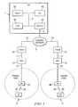
- FIG. 1is a schematic diagram of the functional elements of a wireless communication network compatible with the invention based on an implementing architecture for a CDMA system;
- FIG. 2is a message flow diagram implementing the invention on the CDMA architecture.
- FIG. 3shows details of a modified message used by the invention.
- FIG. 1shows a CDMA wireless telecommunications system compatible with the invention.
- the IP based network 3is coupled to a PDSN 60 via communication link 12 and to another PDSN 61 via communication link 72 .
- the PDSN 60 and PDSN 61are also connected to RNC 10 and RNC 70 via communication links 11 and 71 , respectively.
- the RNC 10is in turn coupled to a Radio Network (RN) 20 , supporting wireless communications within a paging zone 2 , via communication line 21 .
- the RN 20is coupled to an Access Terminal (AT) 30 via wireless communication link 29 .
- the RN 20supports communication within a cell site configured into one or more paging zones 2 .
- the RNC 70is in turn coupled to a Radio Network (RN) 80 , supporting wireless communications within a paging zone 8 , via communication line 81 .
- the RN 80is coupled to an Access Terminal (AT) 90 via wireless communication link 89 .
- the RN 80supports communication within a cell site configured into one or more paging zones 8 .
- the CN 1consists of a Home Subscriber Server (HSS) 35 coupled to the Call Session Control Function (CSCF) 50 and Application Server (AS) 45 connected to each other via a bus line 9 .
- the bus line 9is also connected to a router 40 . Both the bus 9 and the router 40 are part of communication network that may use protocols such as ATM, MPLS, IP, Ethernet etc.
- the router 40is connected to the IP based network 3 via the communication link 4 .
- the AS 40may either be a VoIP server, or a PTT server, or a VT server or a combination thereof.
- the data transmission between the PDSN 60 and RNC 10flows through communication link 12 , thereby permitting communication between the RN 20 and the PDSN 60 .
- the data transmission between PDSN 61 and RNC 70flows through communication link 71 , thereby permitting communication between the RN 80 and the PDSN 61 .
- Data transmission between the CN 1 and PDSN 60flows through the communication links 4 and 12 via the IP based network 3 .
- data transmission between the CN 1 and PDSN 61flows through the communication links 4 and 72 via the IP based network 3 .
- the RNC 10communicates the session specific QoS requirements to RN 20 and instructs it to allocate necessary RF (Radio Frequency) resources to support wireless communications to the AT 30 .
- the RNC 70communicates the session specific QoS requirements to RN 80 and instructs it to allocate necessary RF resources to support wireless communications to the AT 90 .
- the inventionis aimed toward reserving resources to support communications between the AT 30 and the CN 1 broadly and the IP based network 3 specifically. This communication can also take place between the AT 30 and AT 90 via the CN 1 and/or the IP based network 3 .
- the first stepis to identify the application (such as VoIP, PTT, and VT etc.) associated with the transmitted data.
- the PDSN 60identifies the application (such as VoIP, PTT, and VT etc.) based on various characteristics of the incoming data packets. These include the source IP address, the destination IP address, the IP flow identification, the Differentiated Services Code Point (DSCP) values in the packet header (which specifies a per-hop behavior applied to the packet), source port number, destination port number, and other packet/policy attributes.
- DSCPDifferentiated Services Code Point
- the packet/policy attributesare configured in the PDSN 60 by the operators based on the unique packet filtering criteria associated with each application (such as VoIP, PTT, and VT etc.).
- the PDSN 60is configured with a policy value to identify the application (such as VoIP, PTT, and VT etc.) associated with an incoming IP packet that is destined toward the AT 30 .
- the PDSN 60inserts the policy value into the Generic Routing Encapsulation (GRE) header and/or on the DSCP value of the IP header associated with the application (identified earlier based on the packet/policy attributes). This policy value will specify the QoS resource requirements for the specific IP packet.
- GREGeneric Routing Encapsulation
- the PDSN 60performs these functions, they could be performed by the AS 45 , CSCF 50 , router 40 , a gateway, or another server node in the CN 1 .
- the second partis to allocate QoS resources.
- the RNC 10Upon receiving call (or packet data session) setup signaling and resource reservation requests from the originating user, the RNC 10 has enough information to generate a QoS profile required to deliver content and signaling for this specific application (such VoIP, PTT, and VT etc.) session. Based on the QoS requirements for the application (such VoIP, PTT, and VT etc.) represented by the inserted policy value, as configured by the operator of the network, the RNC 10 allocates the required QoS resources to set up the application (such as VoIP, PTT and VT etc.) session.
- the RNC 10maintains an abstract data type that associates a session-in-progress with the QoS profile associated with the policy value.
- the RNC 10sets up or reserves the required RAN resources for completing the application (such as VoIP, PTT and VT etc.) session before announcing the application (such as VoIP, PTT, and VT etc.) session (e.g., a SIP Invite message) to the terminating side.
- the RNC 10receives a response message (such as the “Connection Request+Route Update” message for the CDMA HRPD wireless technology) from the terminating AT 30 , it explicitly reserves resources on the terminating side (e.g. the AT 30 ) by requesting air-link resources that are based on the QoS profile requested by the originating side (e.g.
- Call (or a packet data session) setup timeis considerably reduced by avoiding the resource request/grant handshaking at the terminating side. Lack of resource availability can be translated into aborting the call sooner without degrading network utilization.
- FIG. 2shows a message flow implementing the invention.
- the RNCtransmits a page message and application (such as VoIP, PTT and VT etc.) session specific data to the RN.
- the RNChas the QoS profile requested by the originating side and forwards the QoS profile to the RN.
- the applicationsuch as VoIP, PTT and VT etc.
- the page messageis forwarded to the AT in step 106 .
- the ATprocesses the page and waits for the access cycle to complete in step 107 .
- an Access Channel (ACH) probe requestis sent by the AT containing both a Connection Request (CR) packet and a Route Update (RU) message packet.
- the RNprocesses the ACH probe, and forwards the ACH probe to the RNC, which processes the probe at step 15 .
- the RNCmakes appropriate RAN resource reservations based on the QoS profile once the AT responds.
- the RNCrequests the RN for the required software/hardware and RF resources (such as scheduler queues within the RN's computing entities, MAC indices etc.).
- the RNallocates the requested software/hardware and RF resources in step 119 .
- the RNinforms the RNC that all of the requested software/hardware and RF resources have been secured by sending an ACK (e.g. an ACK for software/hardware and RF resources allocation) message.
- the RNtransmits the application (such as VoIP, PTT and VT etc.) session specific data (e.g., a SIP Invite) data and a RAN QoS resource allocation confirmation (e.g.
- the ATprocesses the application data, and in step 126 , the AT waits for the access cycle to be completed.
- the RNCprocesses the ACK (e.g., an ACK for software/hardware and RF resources allocation) message received from the RN in step 121 .
- the RNCrequests the RN to open a traffic channel by sending a traffic channel initiation (e.g. an OpenTC) message at step 129 .
- a traffic channel initiatione.g. an OpenTC
- the RNprocesses the traffic channel initiation (e.g. an OpenTC) message and transmits an acknowledgement message (e.g., an OpenTCACK) to the RNC in step 133 .
- the RNCprocesses this response in step 135 .
- the RNCinstructs the RN to assign a traffic channel to the AT by sending the appropriate channel assignment (e.g., a traffic channel assignment or TCA) message, and this message (e.g., a TCA) is processed by the RN in step 139 .
- the traffic channelis assigned by forwarding a traffic channel assignment message (e.g., a TCA) to the AT in step 141 .
- step 145the AT completes the access cycle and transmits an acknowledgement to the application (such as VoIP, PTT and VT etc.) session specific message (e.g. a SIP 200 OK) to the RN.
- the message specified in step 145can be transmitted over the signaling resources of the RAN (e.g., a reverse DoS in CDMA HRPD technology).
- the applicationsuch as VoIP, PTT and VT etc.
- session specific messageis shown (in FIG. 2 ) to be sent by the AT after receiving the traffic channel assignment message (e.g., a TCA), that, however, does not preclude the AT from sending this message at any time between steps 123 and 141 .
- the RNforwards the application (such as VoIP, PTT and VT etc.) session specific message to the RNC in step 147 .
- the ATcompletes processing the traffic channel assignment message (e.g. a TCA).
- the ATtransmits a Data Rate Control (DRC) message and a Pilot Acquisition message in step 149 .
- DRCData Rate Control
- the pilot signal in a wireless networkis typically used for the forward link synchronization, coherent detection, soft handoff and for maintaining orthogonality of the AT.
- the RNacquires a Reverse Traffic Channel (RTC) and transmits the RTC information in a RTC Acquired message to the RNC in step 153 .
- the RNCprocesses the RTC acquisition message and transmits an acknowledgment (e.g. an RTC ACK) message to the RN in step 159 .
- the RNtransmits a RTC Acknowledge (e.g., a RTC ACK) to the AT over the Forward Traffic Channel (FTC).
- the ATprocesses the RTC acknowledgement (e.g.
- an RTC ACKtransmits a Traffic Channel Complete (TCC) message, a Reservation Accept (ReservationAccept) message, and a Forward Reservation Acknowledgement (FwdReservationAck) message to the RN over the RTC.
- TCCTraffic Channel Complete
- ReservationAcceptReservation Accept
- FwdReservationAckForward Reservation Acknowledgement
- the AT and the RNbegin communicating traffic data packets in step 169 .
- FIG. 3shows a modified packet data field used by the PDSN in the invention.
- the 1 ⁇ SDB/HRDP Data over Signaling (DoS) Indicator field in the HRPD Interoperability Specification (IOS) standarde.g. 3GPP2 A.S0008-A or TIA-878-A
- IOSHRPD Interoperability Specification
- the PDSNtags the GRE header in the packet for ‘urgent’ or ‘non-urgent’ 1 ⁇ SDB or HRPD DoS transmission as shown in FIG. 3 based on the DSCP value and/or based on another packet filtering mechanism as Traffic Flow Template (TFT) as described by (but not limited to) IS-835 D.
- TFTTraffic Flow Template
- the Type (T 1 ) data field 210has a value of “000 0001” and designates the packet as a Short Data Indication packet.
- the Length (L) data field ( 215 )has a value of 02H.
- the Indicator (I) data field 220has a value of “1” indicating the packet as suitable for 1 ⁇ SDB or HRPD DoS transmission. The value “0” (zero) for the data field 220 has been reserved for future use.
- the SDI/DoS type data field (T 2 ) 225is assigned a value tagging the packet as ‘urgent’ (“1”) or ‘non-urgent’ (“0”) as well as the policy value indicating the application (such as VoIP, PTT, and VT etc.) and the desired QoS treatment.
- the policy values for the data field (T 2 ) 225are as follows.
- the data fields 230 and 235are reserved (RES).
Landscapes
- Engineering & Computer Science (AREA)
- Computer Networks & Wireless Communication (AREA)
- Signal Processing (AREA)
- Mobile Radio Communication Systems (AREA)
- Data Exchanges In Wide-Area Networks (AREA)
Abstract
Description
Claims (30)
Priority Applications (1)
| Application Number | Priority Date | Filing Date | Title |
|---|---|---|---|
| US12/084,270US8825070B2 (en) | 2006-05-24 | 2007-05-24 | Radio resource reservation for wireless networks |
Applications Claiming Priority (3)
| Application Number | Priority Date | Filing Date | Title |
|---|---|---|---|
| US80823306P | 2006-05-24 | 2006-05-24 | |
| US12/084,270US8825070B2 (en) | 2006-05-24 | 2007-05-24 | Radio resource reservation for wireless networks |
| PCT/US2007/012315WO2007139841A2 (en) | 2006-05-24 | 2007-05-24 | Radio resource reservation for wireless networks |
Publications (2)
| Publication Number | Publication Date |
|---|---|
| US20090185527A1 US20090185527A1 (en) | 2009-07-23 |
| US8825070B2true US8825070B2 (en) | 2014-09-02 |
Family
ID=38779194
Family Applications (1)
| Application Number | Title | Priority Date | Filing Date |
|---|---|---|---|
| US12/084,270Expired - Fee RelatedUS8825070B2 (en) | 2006-05-24 | 2007-05-24 | Radio resource reservation for wireless networks |
Country Status (2)
| Country | Link |
|---|---|
| US (1) | US8825070B2 (en) |
| WO (1) | WO2007139841A2 (en) |
Cited By (35)
| Publication number | Priority date | Publication date | Assignee | Title |
|---|---|---|---|---|
| US20140169375A1 (en)* | 2011-05-03 | 2014-06-19 | Cisco Technology, Inc. | Mobile service routing in a network environment |
| US9379931B2 (en) | 2014-05-16 | 2016-06-28 | Cisco Technology, Inc. | System and method for transporting information to services in a network environment |
| US9479443B2 (en) | 2014-05-16 | 2016-10-25 | Cisco Technology, Inc. | System and method for transporting information to services in a network environment |
| US9608896B2 (en) | 2014-03-13 | 2017-03-28 | Cisco Technology, Inc. | Service node originated service chains in a network environment |
| US9762402B2 (en) | 2015-05-20 | 2017-09-12 | Cisco Technology, Inc. | System and method to facilitate the assignment of service functions for service chains in a network environment |
| US10148577B2 (en) | 2014-12-11 | 2018-12-04 | Cisco Technology, Inc. | Network service header metadata for load balancing |
| US10187306B2 (en) | 2016-03-24 | 2019-01-22 | Cisco Technology, Inc. | System and method for improved service chaining |
| US10218616B2 (en) | 2016-07-21 | 2019-02-26 | Cisco Technology, Inc. | Link selection for communication with a service function cluster |
| US10218593B2 (en) | 2016-08-23 | 2019-02-26 | Cisco Technology, Inc. | Identifying sources of packet drops in a service function chain environment |
| US10225187B2 (en) | 2017-03-22 | 2019-03-05 | Cisco Technology, Inc. | System and method for providing a bit indexed service chain |
| US10225270B2 (en) | 2016-08-02 | 2019-03-05 | Cisco Technology, Inc. | Steering of cloned traffic in a service function chain |
| US10237379B2 (en) | 2013-04-26 | 2019-03-19 | Cisco Technology, Inc. | High-efficiency service chaining with agentless service nodes |
| US10257033B2 (en) | 2017-04-12 | 2019-04-09 | Cisco Technology, Inc. | Virtualized network functions and service chaining in serverless computing infrastructure |
| US10320664B2 (en) | 2016-07-21 | 2019-06-11 | Cisco Technology, Inc. | Cloud overlay for operations administration and management |
| US10333855B2 (en) | 2017-04-19 | 2019-06-25 | Cisco Technology, Inc. | Latency reduction in service function paths |
| US10361969B2 (en) | 2016-08-30 | 2019-07-23 | Cisco Technology, Inc. | System and method for managing chained services in a network environment |
| US10397271B2 (en) | 2017-07-11 | 2019-08-27 | Cisco Technology, Inc. | Distributed denial of service mitigation for web conferencing |
| US10417025B2 (en) | 2014-11-18 | 2019-09-17 | Cisco Technology, Inc. | System and method to chain distributed applications in a network environment |
| US10419550B2 (en) | 2016-07-06 | 2019-09-17 | Cisco Technology, Inc. | Automatic service function validation in a virtual network environment |
| US10541893B2 (en) | 2017-10-25 | 2020-01-21 | Cisco Technology, Inc. | System and method for obtaining micro-service telemetry data |
| US10554689B2 (en) | 2017-04-28 | 2020-02-04 | Cisco Technology, Inc. | Secure communication session resumption in a service function chain |
| US10666612B2 (en) | 2018-06-06 | 2020-05-26 | Cisco Technology, Inc. | Service chains for inter-cloud traffic |
| US10673698B2 (en) | 2017-07-21 | 2020-06-02 | Cisco Technology, Inc. | Service function chain optimization using live testing |
| USRE48131E1 (en) | 2014-12-11 | 2020-07-28 | Cisco Technology, Inc. | Metadata augmentation in a service function chain |
| US10735275B2 (en) | 2017-06-16 | 2020-08-04 | Cisco Technology, Inc. | Releasing and retaining resources for use in a NFV environment |
| US10791065B2 (en) | 2017-09-19 | 2020-09-29 | Cisco Technology, Inc. | Systems and methods for providing container attributes as part of OAM techniques |
| US10798187B2 (en) | 2017-06-19 | 2020-10-06 | Cisco Technology, Inc. | Secure service chaining |
| US10884807B2 (en) | 2017-04-12 | 2021-01-05 | Cisco Technology, Inc. | Serverless computing and task scheduling |
| US10931793B2 (en) | 2016-04-26 | 2021-02-23 | Cisco Technology, Inc. | System and method for automated rendering of service chaining |
| US11018981B2 (en) | 2017-10-13 | 2021-05-25 | Cisco Technology, Inc. | System and method for replication container performance and policy validation using real time network traffic |
| US11044203B2 (en) | 2016-01-19 | 2021-06-22 | Cisco Technology, Inc. | System and method for hosting mobile packet core and value-added services using a software defined network and service chains |
| US11063856B2 (en) | 2017-08-24 | 2021-07-13 | Cisco Technology, Inc. | Virtual network function monitoring in a network function virtualization deployment |
| US11503553B1 (en) | 2021-06-24 | 2022-11-15 | T-Mobile Usa, Inc. | Allocation of resource blocks based on traffic priority |
| US11558827B1 (en) | 2021-06-24 | 2023-01-17 | T-Mobile Usa, Inc. | Maximum power reduction based on power headroom |
| US12213037B2 (en) | 2021-12-10 | 2025-01-28 | T-Mobile Usa, Inc. | Network-assisted blanking of shared resources for direct communication links |
Families Citing this family (25)
| Publication number | Priority date | Publication date | Assignee | Title |
|---|---|---|---|---|
| US8914022B2 (en)* | 1992-03-06 | 2014-12-16 | Gogo Llc | System for providing high speed communications service in an airborne wireless cellular network |
| US20110286331A1 (en)* | 1999-08-24 | 2011-11-24 | Gogo Llc | Differentiated Services Code Point Mirroring For Wireless Communications |
| KR100948799B1 (en)* | 2006-08-07 | 2010-03-24 | 삼성전자주식회사 | Resource Allocation Apparatus and Method for Unidirectional Communication in a Broadband Wireless Communication System |
| KR101311258B1 (en)* | 2006-09-28 | 2013-09-25 | 퀄컴 인코포레이티드 | PREDICTIVE QoS RESOURCE ALLOCATION FOR RAPID SESSION ESTABLISHMENT |
| ATE501572T1 (en)* | 2006-09-28 | 2011-03-15 | Qualcomm Inc | BUNDLING COMMUNICATION SIGNALS FOR EFFICIENCY |
| US7813296B2 (en)* | 2006-12-27 | 2010-10-12 | Telefonaktiebolaget L M Ericsson (Publ) | Adapting transmission and reception time in packet based cellular systems |
| US9294401B2 (en)* | 2007-06-28 | 2016-03-22 | Telefonaktiebolaget L M Ericsson (Publ) | Method and apparatus for data transfer in a peer-to-peer network |
| US8462743B2 (en) | 2008-01-25 | 2013-06-11 | Nokia Siemens Networks Oy | Method, apparatus and computer program for signaling channel quality information in a network that employs relay nodes |
| US8250207B2 (en) | 2009-01-28 | 2012-08-21 | Headwater Partners I, Llc | Network based ambient services |
| US20110039562A1 (en)* | 2009-02-05 | 2011-02-17 | Qualcomm Incorporated | Session-specific signaling for multiple access networks over a single access network |
| CN102498479B (en)* | 2009-06-19 | 2015-05-13 | 日本技术贸易株式会社 | Content management device and content management method |
| EP2452470A4 (en)* | 2009-07-10 | 2014-04-30 | Ericsson Telefon Ab L M | METHOD, TERMINAL, ACCESS N UD AND MEDIA SERVER FOR ISSUING MEDIA DIGITAL STREAM RESOURCE ADMISSION CONTROL |
| US8325658B2 (en)* | 2009-07-27 | 2012-12-04 | Qualcomm Incorporated | Quality of service (QoS) resources within a wireless communications system |
| US8620154B2 (en)* | 2009-07-31 | 2013-12-31 | Samsung Electronics Co., Ltd. | Methods and apparatus for fast and energy-efficient light recovery in a visible light communication (VLC) system |
| US8832192B2 (en)* | 2009-09-10 | 2014-09-09 | Sony Corporation | Information processing system, information processing method, information processing device, information processing device control method, information processing terminal, information processing terminal control method, information storage medium and program |
| WO2011035136A1 (en)* | 2009-09-18 | 2011-03-24 | Telesocial, Inc. | Telecommunication service employing an electronic information repository storing social network user, developer, and mobile network operator information |
| US8804518B2 (en) | 2010-02-26 | 2014-08-12 | Qualcomm Incorporated | Quality of service (QoS) acquisition and provisioning within a wireless communications system |
| US8838816B2 (en)* | 2011-02-07 | 2014-09-16 | Futurewei Technologies, Inc. | System and method for remote party restrictions in a communications system |
| US9179381B2 (en) | 2011-09-29 | 2015-11-03 | Qualcomm Incorporated | Reducing network-initiated QoS interruption time when radio and core networks are out of synchronization due to different underlying technologies |
| US8923873B2 (en)* | 2011-11-14 | 2014-12-30 | T-Mobile Usa, Inc. | Device triggered channel selection |
| US9578546B2 (en)* | 2012-08-31 | 2017-02-21 | Qualcomm Incorporated | Directional adjustment to quality of service based on predicted traffic activity on a link |
| US10412618B2 (en)* | 2012-08-31 | 2019-09-10 | Qualcomm Incorporated | Optimistic quality of service set up |
| US9420616B2 (en) | 2012-10-29 | 2016-08-16 | Qualcomm Incorporated | Methods to enhance videotelephony to achieve local QoS |
| US11695826B2 (en)* | 2017-08-14 | 2023-07-04 | Comcast Cable Communications, Llc | Assignment of processing resource based on session data |
| US12177934B2 (en)* | 2019-07-26 | 2024-12-24 | At&T Intellectual Property I, L.P. | User association for integrated access and backhaul for 5G or other next generation network |
Citations (7)
| Publication number | Priority date | Publication date | Assignee | Title |
|---|---|---|---|---|
| US20020099854A1 (en) | 1998-07-10 | 2002-07-25 | Jacob W. Jorgensen | Transmission control protocol/internet protocol (tcp/ip) packet-centric wireless point to multi-point (ptmp) transmission system architecture |
| US20020160812A1 (en)* | 2001-04-26 | 2002-10-31 | Ramin Moshiri-Tafreshi | Channel supervision in a radio network |
| US20040042410A1 (en)* | 2002-08-30 | 2004-03-04 | Harris John M. | SDU and method for dynamically managing wireless call settings |
| US20050014509A1 (en)* | 2003-07-16 | 2005-01-20 | Semper William J. | System and method for controlling quality of service in a wireless network |
| US20050043035A1 (en) | 2003-08-21 | 2005-02-24 | Diesen Michael J. | Method and apparatus for providing multimedia broadcast multicast service data to a subscriber to a multimedia broadcast multicast service |
| US20070025295A1 (en)* | 2005-05-31 | 2007-02-01 | Kyocera Corporation | Radio communication terminal, base station, handoff control method, and base station control method |
| US7720021B1 (en)* | 2006-03-30 | 2010-05-18 | Sprint Spectrum L.P. | Method and system for setting up a call to a mobile station via another mobile station |
- 2007
- 2007-05-24USUS12/084,270patent/US8825070B2/ennot_activeExpired - Fee Related
- 2007-05-24WOPCT/US2007/012315patent/WO2007139841A2/enactiveApplication Filing
Patent Citations (7)
| Publication number | Priority date | Publication date | Assignee | Title |
|---|---|---|---|---|
| US20020099854A1 (en) | 1998-07-10 | 2002-07-25 | Jacob W. Jorgensen | Transmission control protocol/internet protocol (tcp/ip) packet-centric wireless point to multi-point (ptmp) transmission system architecture |
| US20020160812A1 (en)* | 2001-04-26 | 2002-10-31 | Ramin Moshiri-Tafreshi | Channel supervision in a radio network |
| US20040042410A1 (en)* | 2002-08-30 | 2004-03-04 | Harris John M. | SDU and method for dynamically managing wireless call settings |
| US20050014509A1 (en)* | 2003-07-16 | 2005-01-20 | Semper William J. | System and method for controlling quality of service in a wireless network |
| US20050043035A1 (en) | 2003-08-21 | 2005-02-24 | Diesen Michael J. | Method and apparatus for providing multimedia broadcast multicast service data to a subscriber to a multimedia broadcast multicast service |
| US20070025295A1 (en)* | 2005-05-31 | 2007-02-01 | Kyocera Corporation | Radio communication terminal, base station, handoff control method, and base station control method |
| US7720021B1 (en)* | 2006-03-30 | 2010-05-18 | Sprint Spectrum L.P. | Method and system for setting up a call to a mobile station via another mobile station |
Non-Patent Citations (3)
| Title |
|---|
| International Search Authority: Notification of Transmittal of International Search Report, Written Opinion of Int'l Searching Authority, or the Declaration dated Jan. 7, 2008. |
| International Searching Authority: International Search Report dated Jan. 7, 2008. |
| International Searching Authority: Written Opinion of the International Searching Authority dated Jan. 7, 2008. |
Cited By (52)
| Publication number | Priority date | Publication date | Assignee | Title |
|---|---|---|---|---|
| US9860790B2 (en) | 2011-05-03 | 2018-01-02 | Cisco Technology, Inc. | Mobile service routing in a network environment |
| US9143438B2 (en)* | 2011-05-03 | 2015-09-22 | Cisco Technology, Inc. | Mobile service routing in a network environment |
| US20140169375A1 (en)* | 2011-05-03 | 2014-06-19 | Cisco Technology, Inc. | Mobile service routing in a network environment |
| US10237379B2 (en) | 2013-04-26 | 2019-03-19 | Cisco Technology, Inc. | High-efficiency service chaining with agentless service nodes |
| US9608896B2 (en) | 2014-03-13 | 2017-03-28 | Cisco Technology, Inc. | Service node originated service chains in a network environment |
| US9479443B2 (en) | 2014-05-16 | 2016-10-25 | Cisco Technology, Inc. | System and method for transporting information to services in a network environment |
| US9379931B2 (en) | 2014-05-16 | 2016-06-28 | Cisco Technology, Inc. | System and method for transporting information to services in a network environment |
| US10417025B2 (en) | 2014-11-18 | 2019-09-17 | Cisco Technology, Inc. | System and method to chain distributed applications in a network environment |
| US10148577B2 (en) | 2014-12-11 | 2018-12-04 | Cisco Technology, Inc. | Network service header metadata for load balancing |
| USRE48131E1 (en) | 2014-12-11 | 2020-07-28 | Cisco Technology, Inc. | Metadata augmentation in a service function chain |
| US9762402B2 (en) | 2015-05-20 | 2017-09-12 | Cisco Technology, Inc. | System and method to facilitate the assignment of service functions for service chains in a network environment |
| US9825769B2 (en) | 2015-05-20 | 2017-11-21 | Cisco Technology, Inc. | System and method to facilitate the assignment of service functions for service chains in a network environment |
| US11044203B2 (en) | 2016-01-19 | 2021-06-22 | Cisco Technology, Inc. | System and method for hosting mobile packet core and value-added services using a software defined network and service chains |
| US10187306B2 (en) | 2016-03-24 | 2019-01-22 | Cisco Technology, Inc. | System and method for improved service chaining |
| US10812378B2 (en) | 2016-03-24 | 2020-10-20 | Cisco Technology, Inc. | System and method for improved service chaining |
| US10931793B2 (en) | 2016-04-26 | 2021-02-23 | Cisco Technology, Inc. | System and method for automated rendering of service chaining |
| US10419550B2 (en) | 2016-07-06 | 2019-09-17 | Cisco Technology, Inc. | Automatic service function validation in a virtual network environment |
| US10320664B2 (en) | 2016-07-21 | 2019-06-11 | Cisco Technology, Inc. | Cloud overlay for operations administration and management |
| US10218616B2 (en) | 2016-07-21 | 2019-02-26 | Cisco Technology, Inc. | Link selection for communication with a service function cluster |
| US10225270B2 (en) | 2016-08-02 | 2019-03-05 | Cisco Technology, Inc. | Steering of cloned traffic in a service function chain |
| US10218593B2 (en) | 2016-08-23 | 2019-02-26 | Cisco Technology, Inc. | Identifying sources of packet drops in a service function chain environment |
| US10778551B2 (en) | 2016-08-23 | 2020-09-15 | Cisco Technology, Inc. | Identifying sources of packet drops in a service function chain environment |
| US10361969B2 (en) | 2016-08-30 | 2019-07-23 | Cisco Technology, Inc. | System and method for managing chained services in a network environment |
| US10778576B2 (en) | 2017-03-22 | 2020-09-15 | Cisco Technology, Inc. | System and method for providing a bit indexed service chain |
| US10225187B2 (en) | 2017-03-22 | 2019-03-05 | Cisco Technology, Inc. | System and method for providing a bit indexed service chain |
| US10884807B2 (en) | 2017-04-12 | 2021-01-05 | Cisco Technology, Inc. | Serverless computing and task scheduling |
| US10257033B2 (en) | 2017-04-12 | 2019-04-09 | Cisco Technology, Inc. | Virtualized network functions and service chaining in serverless computing infrastructure |
| US10938677B2 (en) | 2017-04-12 | 2021-03-02 | Cisco Technology, Inc. | Virtualized network functions and service chaining in serverless computing infrastructure |
| US11102135B2 (en) | 2017-04-19 | 2021-08-24 | Cisco Technology, Inc. | Latency reduction in service function paths |
| US10333855B2 (en) | 2017-04-19 | 2019-06-25 | Cisco Technology, Inc. | Latency reduction in service function paths |
| US10554689B2 (en) | 2017-04-28 | 2020-02-04 | Cisco Technology, Inc. | Secure communication session resumption in a service function chain |
| US11539747B2 (en) | 2017-04-28 | 2022-12-27 | Cisco Technology, Inc. | Secure communication session resumption in a service function chain |
| US12028378B2 (en) | 2017-04-28 | 2024-07-02 | Cisco Technology, Inc. | Secure communication session resumption in a service function chain preliminary class |
| US10735275B2 (en) | 2017-06-16 | 2020-08-04 | Cisco Technology, Inc. | Releasing and retaining resources for use in a NFV environment |
| US11196640B2 (en) | 2017-06-16 | 2021-12-07 | Cisco Technology, Inc. | Releasing and retaining resources for use in a NFV environment |
| US10798187B2 (en) | 2017-06-19 | 2020-10-06 | Cisco Technology, Inc. | Secure service chaining |
| US10397271B2 (en) | 2017-07-11 | 2019-08-27 | Cisco Technology, Inc. | Distributed denial of service mitigation for web conferencing |
| US11108814B2 (en) | 2017-07-11 | 2021-08-31 | Cisco Technology, Inc. | Distributed denial of service mitigation for web conferencing |
| US10673698B2 (en) | 2017-07-21 | 2020-06-02 | Cisco Technology, Inc. | Service function chain optimization using live testing |
| US11115276B2 (en) | 2017-07-21 | 2021-09-07 | Cisco Technology, Inc. | Service function chain optimization using live testing |
| US11063856B2 (en) | 2017-08-24 | 2021-07-13 | Cisco Technology, Inc. | Virtual network function monitoring in a network function virtualization deployment |
| US10791065B2 (en) | 2017-09-19 | 2020-09-29 | Cisco Technology, Inc. | Systems and methods for providing container attributes as part of OAM techniques |
| US11018981B2 (en) | 2017-10-13 | 2021-05-25 | Cisco Technology, Inc. | System and method for replication container performance and policy validation using real time network traffic |
| US10541893B2 (en) | 2017-10-25 | 2020-01-21 | Cisco Technology, Inc. | System and method for obtaining micro-service telemetry data |
| US11252063B2 (en) | 2017-10-25 | 2022-02-15 | Cisco Technology, Inc. | System and method for obtaining micro-service telemetry data |
| US11122008B2 (en) | 2018-06-06 | 2021-09-14 | Cisco Technology, Inc. | Service chains for inter-cloud traffic |
| US11799821B2 (en) | 2018-06-06 | 2023-10-24 | Cisco Technology, Inc. | Service chains for inter-cloud traffic |
| US10666612B2 (en) | 2018-06-06 | 2020-05-26 | Cisco Technology, Inc. | Service chains for inter-cloud traffic |
| US11503553B1 (en) | 2021-06-24 | 2022-11-15 | T-Mobile Usa, Inc. | Allocation of resource blocks based on traffic priority |
| US11558827B1 (en) | 2021-06-24 | 2023-01-17 | T-Mobile Usa, Inc. | Maximum power reduction based on power headroom |
| US12356341B2 (en) | 2021-06-24 | 2025-07-08 | T-Mobile Usa, Inc. | Maximum power reduction based on traffic priority |
| US12213037B2 (en) | 2021-12-10 | 2025-01-28 | T-Mobile Usa, Inc. | Network-assisted blanking of shared resources for direct communication links |
Also Published As
| Publication number | Publication date |
|---|---|
| US20090185527A1 (en) | 2009-07-23 |
| WO2007139841A2 (en) | 2007-12-06 |
| WO2007139841A3 (en) | 2008-03-06 |
Similar Documents
| Publication | Publication Date | Title |
|---|---|---|
| US8825070B2 (en) | Radio resource reservation for wireless networks | |
| EP1120939B1 (en) | Method, server and arrangement in a communication network | |
| EP1382214B1 (en) | Binding information for ip media flows | |
| RU2449489C2 (en) | Support of multiple communication lines for systems of mobility network control | |
| JP3433186B2 (en) | Handover between mobile communication networks | |
| US8355413B2 (en) | Policy based procedure to modify or change granted QoS in real time for CDMA wireless networks | |
| AU2005222894B2 (en) | Method, apparatus and computer program product providing quality of service support in a wireless communications system | |
| KR101532524B1 (en) | SELECTIVELY PROVISIONING CALL SETUP QUALITY OF SERVICE (QoS) RESOURCE RESERVATIONS DURING A COMMUNICATION SESSION WITHIN A WIRELESS COMMUNICATIONS SYSTEM | |
| US20020093948A1 (en) | Packet-based multimedia communications system having one or more wireless links | |
| JP2007525889A (en) | Method and apparatus for providing end-to-end QoS | |
| US20050220069A1 (en) | Method for providing bearer specific information for wireless networks | |
| US7894815B2 (en) | Device for providing hand-off quality of service of inter-access systems and method thereof | |
| TWI328375B (en) | Method and apparatus for flow treatment and mapping on multicast/broadcast services | |
| US20150103653A1 (en) | Conserving network capacity by releasing qos resources | |
| JP2002534923A (en) | Transport of QoS mapping information in packet radio networks | |
| EP1982475A1 (en) | Method and devices for installing packet filters in a data transmission | |
| US10404604B2 (en) | Telecommunications system and method | |
| JP2010506459A (en) | Predictive QoS resource allocation for rapid session establishment | |
| JP2009531915A (en) | Telecommunication system and telecommunication method | |
| EP1380182B1 (en) | One-to-one communication in a system having different control plane and user plane logical entities | |
| JP5242792B2 (en) | Method for supporting a quality of service mechanism during a handover process or during preparation of a handover process | |
| KR100901358B1 (en) | Method and system for guaranteeing END application of application service considering wireless environment |
Legal Events
| Date | Code | Title | Description |
|---|---|---|---|
| AS | Assignment | Owner name:NORTEL NETWORKS LIMITED, CANADA Free format text:ASSIGNMENT OF ASSIGNORS INTEREST;ASSIGNORS:AKHTAR, HASEEB;PILLAI, KRISHNAKUMAR;SIGNING DATES FROM 20070522 TO 20070525;REEL/FRAME:020925/0828 | |
| AS | Assignment | Owner name:ROCKSTAR BIDCO, LP, NEW YORK Free format text:ASSIGNMENT OF ASSIGNORS INTEREST;ASSIGNOR:NORTEL NETWORKS LIMITED;REEL/FRAME:027143/0717 Effective date:20110729 | |
| AS | Assignment | Owner name:NORTEL NETWORKS LIMITED, CANADA Free format text:CORRECTIVE ASSIGNMENT TO CORRECT THE SERIAL NUMBER OF APPLICATION BEING ASSIGNED PREVIOUSLY RECORDED ON REEL 020925 FRAME 0828. ASSIGNOR(S) HEREBY CONFIRMS THE THE SERIAL NUMBER OF THE APPLICATION SHOULD BE LISTED AS-- SERIAL NUMBER: 12084270;ASSIGNORS:AKHTAR, HASEEB;PILLAI, KRISHNAKUMAR;SIGNING DATES FROM 20070522 TO 20070525;REEL/FRAME:027588/0479 | |
| AS | Assignment | Owner name:APPLE INC., CALIFORNIA Free format text:ASSIGNMENT OF ASSIGNORS INTEREST;ASSIGNOR:ROCKSTAR BIDCO, LP;REEL/FRAME:028570/0938 Effective date:20120511 | |
| FEPP | Fee payment procedure | Free format text:PAYOR NUMBER ASSIGNED (ORIGINAL EVENT CODE: ASPN); ENTITY STATUS OF PATENT OWNER: LARGE ENTITY | |
| STCF | Information on status: patent grant | Free format text:PATENTED CASE | |
| MAFP | Maintenance fee payment | Free format text:PAYMENT OF MAINTENANCE FEE, 4TH YEAR, LARGE ENTITY (ORIGINAL EVENT CODE: M1551) Year of fee payment:4 | |
| FEPP | Fee payment procedure | Free format text:MAINTENANCE FEE REMINDER MAILED (ORIGINAL EVENT CODE: REM.); ENTITY STATUS OF PATENT OWNER: LARGE ENTITY | |
| LAPS | Lapse for failure to pay maintenance fees | Free format text:PATENT EXPIRED FOR FAILURE TO PAY MAINTENANCE FEES (ORIGINAL EVENT CODE: EXP.); ENTITY STATUS OF PATENT OWNER: LARGE ENTITY | |
| STCH | Information on status: patent discontinuation | Free format text:PATENT EXPIRED DUE TO NONPAYMENT OF MAINTENANCE FEES UNDER 37 CFR 1.362 | |
| FP | Lapsed due to failure to pay maintenance fee | Effective date:20220902 |