US8823577B2 - Distance separation tracking system - Google Patents
Distance separation tracking systemDownload PDFInfo
- Publication number
- US8823577B2 US8823577B2US12/974,672US97467210AUS8823577B2US 8823577 B2US8823577 B2US 8823577B2US 97467210 AUS97467210 AUS 97467210AUS 8823577 B2US8823577 B2US 8823577B2
- Authority
- US
- United States
- Prior art keywords
- signal
- periodic
- transceiver
- distance separation
- return
- Prior art date
- Legal status (The legal status is an assumption and is not a legal conclusion. Google has not performed a legal analysis and makes no representation as to the accuracy of the status listed.)
- Expired - Fee Related, expires
Links
Images


Classifications
- G—PHYSICS
- G01—MEASURING; TESTING
- G01S—RADIO DIRECTION-FINDING; RADIO NAVIGATION; DETERMINING DISTANCE OR VELOCITY BY USE OF RADIO WAVES; LOCATING OR PRESENCE-DETECTING BY USE OF THE REFLECTION OR RERADIATION OF RADIO WAVES; ANALOGOUS ARRANGEMENTS USING OTHER WAVES
- G01S13/00—Systems using the reflection or reradiation of radio waves, e.g. radar systems; Analogous systems using reflection or reradiation of waves whose nature or wavelength is irrelevant or unspecified
- G01S13/74—Systems using reradiation of radio waves, e.g. secondary radar systems; Analogous systems
- G01S13/82—Systems using reradiation of radio waves, e.g. secondary radar systems; Analogous systems wherein continuous-type signals are transmitted
- G01S13/84—Systems using reradiation of radio waves, e.g. secondary radar systems; Analogous systems wherein continuous-type signals are transmitted for distance determination by phase measurement
- G—PHYSICS
- G01—MEASURING; TESTING
- G01S—RADIO DIRECTION-FINDING; RADIO NAVIGATION; DETERMINING DISTANCE OR VELOCITY BY USE OF RADIO WAVES; LOCATING OR PRESENCE-DETECTING BY USE OF THE REFLECTION OR RERADIATION OF RADIO WAVES; ANALOGOUS ARRANGEMENTS USING OTHER WAVES
- G01S13/00—Systems using the reflection or reradiation of radio waves, e.g. radar systems; Analogous systems using reflection or reradiation of waves whose nature or wavelength is irrelevant or unspecified
- G01S13/02—Systems using reflection of radio waves, e.g. primary radar systems; Analogous systems
- G01S13/06—Systems determining position data of a target
- G01S13/46—Indirect determination of position data
- G01S2013/466—Indirect determination of position data by Trilateration, i.e. two antennas or two sensors determine separately the distance to a target, whereby with the knowledge of the baseline length, i.e. the distance between the antennas or sensors, the position data of the target is determined
Definitions
- the present inventionin general relates to a process and equipment for determining the distance separation between two transceivers, and in particular to the use of a periodic wave signal completing a sent and received circuit to derive a time of flight between transceivers that is manipulated along with the known characteristics of the periodic signal to derive distance separation between the transceivers.
- a variety of endeavorsrequire determination of distance separation between objects. Such endeavors include aeronautics, emergency responders, surveying, biology field studies, and personnel management within large organizations. Range finding to a passive target that lacks a transceiver communicative with a system transceiver has historically been accomplished with triangulation or time of flight of an interrogating optical or radar pulse to the target and back to the system transceiver. These passive range finding systems are prone to distortions when line of sight conditions do not exist and are obscured by intermediate terrain and structures through which interrogating signals cannot penetrate. Additionally, radar systems are unable to provide high resolution distance separation information with an accuracy less than the radar wavelength scale.
- Distance separationhas also been previously determined using two communicative transceivers.
- communicative active transceiversdistance separation is either calculated by absolute or relative techniques with absolute techniques utilizing distances or angles to known reference locations to calculate a target position.
- absolute techniquesare global positioning satellite (GPS) based systems, triangulation methods, and trilateration.
- relative trackinginvolves a larger mobile unit that is tracked precisely in absolute coordinates using GPS or other tracking technologies while the actual target is then tracked with respect to the intermediate target.
- existing absolute and relative tracking techniqueshave all suffered from one or more of the following shortcomings including large transceiver size and power consumption, the requirement of clock synchronization that is vulnerable to air and disruption, limited penetration through land masses and/or manmade structures, or complexity of calculation. Attempts to add a distance separation tracking functionality onto existing communication devices that operate from 0.9-100 gigaHertz and in particular to industrial, scientific, and medical (ISM) 2.4 gigaHertz protocols have compounded these difficulties.
- ISMindustrial, scientific, and medical
- a distance separation tracking processincludes the transmission of a periodic radio frequency original signal from a beacon transceiver.
- the original periodic signal from the beacon transceiveris received at a remote target transceiver as a target received periodic signal.
- the targetretransmits the received periodic signal to the beacon transceiver as a return periodic signal.
- Data points of the return periodic signalare sampled and used to calculate a phase differential between the original periodic signal and the return periodic signal that correlates to the distance separation range between the beacon receiver and the target transceiver.
- sampling data points of the returned periodic signaloccur at a sampling rate at least twice the frequency of the original signal.
- a distance separation tracking processis also provided based upon a master beacon transceiver that has a known position. The above-detailed process is otherwise repeated to afford a point of reference for the distance separation range. With a known position transmitter or master beacon, the calculated distance separation range is used in an absolute reference frame positioning system.
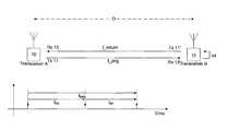
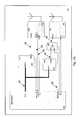
- FIG. 1Ais a diagram depicting periodic signal path between a first transceiver denoted as transceiver A (beacon) and a second transceiver denoted as transceiver B (target) along with a plot of time of arrival for segments A ⁇ B, t AB , B ⁇ A, t BA , and total path A ⁇ B ⁇ A, t ABA from which a time of arrival (TOA) is calculated to determine distance separation;
- TOAtime of arrival
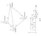
- FIG. 1Bis a diagram of a multiple transceiver embodiment in which a target receiver X need not retransmit a received signal to determine distance separate to transmitter A and transceivers B and C;
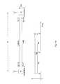
- FIG. 2is a plot of a simulated 50 kHz sine wave outward signal A ⁇ B, overlaid with return signal B ⁇ A based on a sampling period of 1 microsecond, a 0.2 millisecond sampling frame (200 samples), and a 5% random amplitude noise addition on the return signal;
- FIG. 3is a plot of distance separation (range) as a function of time for a 50 kHz outward sine wave signal based on a sampling period of 1 microsecond, 2 millisecond sampling frames (2000 samples), and a 5% random amplitude noise addition on the return signal to derive a simulated distance separation;
- FIGS. 4A-4Care plots of data capture and processing according to a first embodiment of the present invention.
- FIG. 4Ais a plot of outward (solid) and returned (dashed) signals produced by a working example of the present invention with sampling points depicted as points.
- FIG. 4Bdepicts the error as a function of time derived from the sampling points of FIG. 4A .
- FIG. 4Cdepicts a plot of distance separation based on estimated distance separation and a best fit average filter of the estimated distance separation;
- FIG. 5is a diagram of hardware with two channel transmitter/receiver (Tx/Rx) transceiver A (beacon) and transceiver B (target);
- FIG. 6Ais a block diagram of a prior art receiver operative in a beacon or target transceiver of the present invention
- FIG. 6Bis a block diagram of a prior art transmitter operative in a beacon or target transceiver of the present invention.
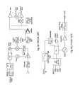
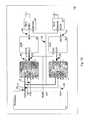
- FIG. 7Ais a hardware diagram of a first embodiment of transceiver A according to the present invention.
- FIG. 7Bis a hardware diagram of a second embodiment of transceiver A according to the present invention wherein this embodiment is used to measure distance using Time Of Arrival (TOA); and
- TOATime Of Arrival
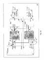
- FIG. 7Cis a hardware diagram of an embodiment of receiver X according to the present invention used to measure distance using Time Difference Of Arrival (TDOA).
- TDOATime Difference Of Arrival
- the present inventionhas utility as a process and system for determining distance separation between a first transceiver and a second transceiver with a high degree of accuracy in spite of intermediate obstructions and without reliance on GPS, fixed reference signals, or line of sight.
- the return signalhas a time delay shift associated directly with the distance traveled; and most importantly, signal distortion during transit is readily removed through selection of a periodic signal having a frequency of between 10 and 2,400 kiloHertz and preferably between 20 and 800 kiloHertz, and most preferably between 25 and 300 kiloHertz.
- the periodic signalhas a desirable set of characteristics as to differing structure penetration, allowance for a rapid sampling rate to achieve a good signal-to-noise ratio for subsequent sampling, available inexpensive and robust hardware components, and highly accurate distance separation determination. It is appreciated that use of a periodic signal in this frequency range also achieves greater operational range as compared to systems operating on the ISM or other higher frequency standards. Further, by removing the necessity for clock synchronization between transceivers, the more robust and accurate distance separation is achieved.
- beacon transceiveror “beacon” is used to indicate a transceiver from which distance is measured.
- a “target transceiver” or “target”is a transceiver or receiver whose distance is measured from a beacon transceiver.
- Each transceiveroptionally includes a receiver and a transmitter.
- An inventive distance separation tracking processuses a hardwired loop-backed connection in the target to receive the outward signal transmitted from a beacon to rebroadcast the signal as a return signal thereby eliminating phase distortion or the need for clock synchronization that have plagued prior art systems.
- FIG. 1AAn inventive process for distance separation tracking is provided schematically in FIG. 1A and includes a first transceiver, synonymously denoted as transceiver A (beacon) at 10 .
- Transceiver Abroadcasts a periodic frequency signal across an unknown distance separation D to a second transceiver, synonymously denoted as transceiver B (target) at 12 .
- Transceiver B 12has a hardwired loop 14 between receiver 13 ′ and a transmitter 11 ′ within the transceiver 12 .
- the transmitter 11 ′rebroadcasts the periodic frequency signal received by way of receiver 13 ′ and hardwired loop 14 and through rebroadcast periodic frequency signal f return is collected at receiver 13 of beacon transceiver 10 .
- the periodic frequency signal f origis selected to have a waveform that is modeled accurately by a mathematical formula. Illustrative of various waveforms for the periodic frequency signal f orig are sine wave, square wave, triangle wave, and sawtooth.
- the original periodic frequency signal f origis a waveform that has only a single variable, and maximizes the available channel bandwidth utilization.
- a sine waverepresents a preferred waveform for the original periodic frequency signal f orig .
- a calculation of the distance separation D between beacon transceiver 10 and target transceiver 12is derived from time delay of the return signal f return relative to the transmitted signal f orig from 10 .
- the distance separation Dis treated as a constant during the sampling of return signal f return .
- t ABthe time for signal f orig to travel from transmitter 11 to receiver 13 ′ is denoted schematically as t AB of the time associated with the return signal transit from receiver 13 ′ through hardwire loop 14 to transmission from transmitter 11 ′ to receiver 13 is denoted schematically in FIG. 1A as t BA while the complete round trip transit of signals f orig +f return is denoted as t ABA .
- beacon transceiver 10While an inventive process is depicted with a single beacon transceiver 10 and a single target loop-backed transceiver 12 for visual clarity to simply illustrate the mode of operation of an inventive distance separation tracking process, it is appreciated that a more complex system is readily produced with multiple beacon transceivers 10 and/or loop-backed target transceivers 12 upon provision of separate channels within each such transceiver 10 or 12 , and each beacon transceiver 10 broadcasting a periodic frequency signal f orig at different channels such as by different waveform, period, or combination thereof. In this way, multiple distance separations are simultaneously calculated.
- the same channelsmay be used by multiple loop-backed target transceivers, and that the loopback in each transceiver is activated only when the loop-backed transceiver receives a signal f orig from the beacon initiating transceiver with a specific frequency or waveform, uniquely indicating a request from the specific loop-backed target transceiver.
- Multiple transceiversmay use the same channels for receiving and transmitting the frequency signal, assuming that the chance of signal collision is relatively small. For example, with 100 transceivers requesting 1 measurement per second, and the duration of each measurement being 1 ms, there is a 10% chance of collision.
- plotting distance separation onto a terrain map or building floor planallows for highly accurate monitoring of distance separation tracking in actual space with the distance separation tracking being robust and able to operate through quantities of geologic structure or through manmade structures.
- an inventive systemis considered to be particularly useful in tracking the relative position of first responders, miners, and mobile equipment operating within an environment such as submersibles, robots, drilling components, roving service equipment, and the like.
- a conventional two-way radio systemis readily modified to transmit a periodic frequency signal as a signal packet as a disruption on an audio channel to provide a distance separation capability,
- a typical periodic frequency signalis of a duration that is barely perceptible to a listener. Typical packet duration is 0.1 to 10 milliseconds.
- the timing of the packet transmissionis optionally at random times to make the perceptidn of the packet similar to that of random noise.
- the present inventionis also operative with a master transmitter 20 transmitting a periodic original frequency signal 21 (f master ) to one or more loop-backed beacon transceivers 22 and 24 which in turn broadcast the periodic original signal as a retransmitted original signal (f orig ) 23 and 25 to a receiver 26 .
- Receiver 26receives one or more signals f orig 0 . . . f orig n where n corresponds to the number of periodic frequency signals so received by the receiver.
- the receiver 26uses time difference of arrival (TDOA) to derive distance separation to the broadcasting transmitter and transceivers.
- TDOAtime difference of arrival
- the receivermay use a polling method to switch channels, in order to conduct a TDOA distance measurement with different combinations of signals from different transmitters and transceivers. For example, receiver 26 may select channel A for transmitter A and channel B for transceiver B, so that a distance measurement is calculated using the TDOA between signals from transmitter A and transceiver B. Or receiver 26 may select channel A for transmitter A and channel C for transceiver C, so that a distance measurement is calculated using the TDOA between signals from transmitter A and transceiver C. Time difference of arrival calculation protocols are well known (Ref. 1-10).
- a master transmitter 20which broadcasts a signal to a beacon transceiver 22 which in turn rebroadcasts the periodic signal f orig to a target receiver 26
- a target receiver 26is particularly well suited for use with multiple targets as each target receiver need not include a transmitter and instead with additional channels for separately receiving the signal from master transmitter 20 , f master and the rebroadcast form thereof f orig , distance separation at target receiver 26 is readily determined without the need for target retransmission of a received signal. Since in this configuration, the target is only receiving, the system is well suited for scaling up to a large number of moving targets, without increased occupation of the channel bandwidth.
- master transmitter Atransmits a signal on channel A.
- Beacon transceiver Breceives the signal from master transmitter A on channel A and retransmits the signal on channel B.
- beacon transceiver Creceives the signal from master transmitter A on channel A, and retransmits it on channel C.
- a receiver Xmay scan channels A, B and C for signals from master transmitter A, and beacon transceivers B and/or C. Assuming that receiver X knows the coordinates of the master transmitter and beacon transceivers, it can use the time difference of arrival (measured from the phase difference in the channel data) to determine relative position to the transmitter and transceivers.
- This inventive embodimentis shown schematically in FIG. 1B . This embodiment has the advantage over prior systems at least due to the signal loop-back (therefore not requiring synchronization) and the use of a math signal.
- a 50 kiloHertz sine wave free of distortionis used to simulate a periodic frequency signal.
- a return signalis simulated that includes 5% random amplitude noise added to the original signal as f return .
- a sample period of 1 microsecondis used along with a 0.2 millisecond frame length.
- the resultant sine waves of the original and return signals as well as the sampling pointsare depicted schematically in FIG. 2 at a distance separation between beacon transceiver 10 and target transceiver 12 of 10 feet.
- FIG. 3illustrates a plot of a distance separation as a function of time for a 50 kiloHertz outward sine wave signal sampled over 2 millisecond frame lengths at a sampling period of 1 microsecond (2000 sample points) based on an optimal fit for Equation 3 accurately returns a simulated range measurement based on a 10 foot separation between beacon transceiver and target transceiver simulated to have an actual separation of 10 feet.
- a multiple channel transceiver operative in the present inventionis readily available commercially that only requires that each transceiver channel have a frequency bandwidth for each channel such that disparate channels do not have frequency overlap.
- periodic frequency signalsare on the order of kiloHertz and sampling rates on the order of megaHertz
- channel specificationsare readily detailed.
- channel 1needs a range of 31 megaHertz ⁇ 75 kiloHertz.
- FIG. 5a schematic is provided in FIG. 5 that adds detail with respect to the beacon transceiver 10 of FIG. 1 .
- the beacon transceiver 10has a microcontroller (MCU) 52 that generates a periodic signal which is fed to a digital-to-analog converter (DAC) subcircuit 54 .
- the processed periodic signal leaving the DAC 54is denoted at 56 and is sent to transmitter 11 which transmits f orig on channel 1 in the example provided of FIG. 5 . It is appreciated that the numerical numbering of channels is wholly arbitrary.
- Receiver 13 ′ of target transceiver 12receives f orig that after passing through hardwired loop 14 rebroadcasts f return with transmitter 11 ′ on channel 2 as f return .
- f returnis received by receiver 13 on channel 2 with the received signal 58 communicated to an analog-to-digital converter (ADC) subcircuit 60 within the microcontroller 52 .
- ADCanalog-to-digital converter
- Commercially available receiver and transmitter block diagrams available as prior artare shown respectively at FIGS. 6A and 6B and are noted to be operative herein as receivers 13 or 13 ′, or transmitters 11 or 11 ′.
- direct access to analog signal input of the transmitter and analog output of the receiveris provided.
- analog signals that do not pass through analog-to-digital or digital-to-analog converters or filtersare free from possible phase delays, distortion, or time quantization errors created by such devices.
- a multiple channel embodiment depicted in FIG. 1Bhas switching and locking properties between various channels on the order of milliseconds.
- switching and locking between channelsoccurs in less than 5 milliseconds and preferably less than 2 milliseconds.
- an inventive receiver 13provides a value for signal strength to master controller 52 . It is appreciated that the inventive system as detailed in FIG. 5 is particularly well suited for rendering transceivers 10 and 12 in compact and lightweight form amenable to being hand held or as an attachment to apparel of a human or further miniaturized for attachment to other mammals.
- FIG. 7Aprovides a hardware beta diagram for beacon transceiver 10 as shown in schematic form in FIG. 5 .
- the ADC 40 and DAC 41are external to the processor 52 .
- the receiver module 13communicates analog audio signals 43 via its audio output to the analog input of the ADC 40 which are then converted to a digital format by the ADC 40 and communicated to the processor 52 via the digital data bus 49 .
- the receiver module 13is also capable of decoding the incoming audio signal into a serial digital signal 44 which it communicates to the processor 52 .
- the receiver module 13also communicates a signal 45 corresponding to the signal strength of the received signal 43 to the processor 52 .
- the processor 52sends digital audio data to the transmitter module 11 via the digital data bus 49 .
- the digital datais converted to analog data by the DAC 41 .
- the analog output 47 of the DACis then routed through the switch 42 appearing as the signal 46 and communicated to the transmitter module 11 .
- the processor 52may communicate serial digital data 48 to the transmitter module 11 via the switch 42 .
- FIG. 7Bprovides a hardware beta diagram for beacon transceiver 10 as shown in schematic form in FIG. 5 .
- the ADC 40 and DAC 41are external to the processor 52 and utilize first-in first-out buffers (FIFO's) to communicate with the processor.
- the processor 52writes data to be transmitted to FIFO 64 ′ via the data bus 49 with properly configured interface lines 73 , 75 , 76 , 77 and 78 . Transmission and reception of data occur simultaneously.
- the processor 52initiates transmission of data by properly configuring interface lines 73 , 75 , 76 , 77 and 78 while providing a clock signal 70 to FIFO 64 ′ and DAC 41 .
- Clock signal 70enables the signal previously stored in the FIFO 64 ′ to be driven into the DAC 41 .
- Clock signal 70transfers data from FIFO 64 ′ to DAC 41 which DAC 41 converts to an analog signal 46 provided to the transmitter 11 .
- the receiver 13provides an analog signal 43 to the ADC 40 which is converted to a digital signal 72 when driven by clock signal 70 .
- Clock signal 70also clocks digital signal 72 into FIFO 64 .
- Processor 52then reads stored digital signal 72 from FIFO 64 via data bus 49 .
- a serial peripheral interface 74provides a means to accommodate channel switching of receiver 13 and transmitter 11 .
- FIG. 7Cprovides a multiple receiver channel version of the invention, as for example, might be used in the system detailed with respect to FIG. 1B .
- Duplicate receiver and corresponding ADCare designated as 13 ′′ and 40 ′, respectively, and otherwise share the characteristics of the unprimed versions of these numerals.
- FIFO 64 and 64 ′′provide intermediate signal communications between ADCs 40 , 40 ′ and the microcontroller 52 .
- a serial peripheral interface 74provides a means to accommodate channel switching of the receivers 13 and 13 ′′
- a distance separationis readily calculated by a variety of data analysis protocols conventional to the art that illustratively include statistical phase delay values derived from each data point such as average or medium, regression fitting, combinatorial optimization, random optimization, and stochastic approximation and quadratic optimization routines.
- calculation of distance separation Dis obtained through an inventive optimization process that involves using sampling points of f return centered around the periodic signal time axis and in particular with respect to a sine wave around the points of inflexion. This is depicted graphically in FIG. 4A where f orig , f return and eligible sampling points of f return are overlapped.
- extrema sampling points of a sine wave and edge points of other periodic wavesoffer the greatest degree of distortion between f orig and f return . This is in fact observed in FIG. 4A .
- error plotted between f orig and f return and a filtering windowis applied to the error data to provide an error band that discards, for example, the extreme 5%, 10%, 15%, 20%, etc. of the error band from subsequent calculations used to derive a distance separation D.
- a calculated and filtered distanceis provided in FIG. 4C .
- the rate of change of the average filteris communicated as part of the data analysis routine to the error band filtering function to modify error bandwidth and percentage of extreme point discard to provide stability to the average filter value of the calculated and filtered distance obtained in FIG. 4C .
- the beacon transceiver of FIG. 7Agenerated a sine wave f orig having a frequency of 22 kiloHertz as depicted in FIG. 4A .
- the signal f origis broadcast and received by a target transceiver having hardwired looped receiver and transmitter components per FIGS. 6A and 6B with a signal f return being received with the beacon transceiver as shown in FIG. 4A .
- a distance calculation within 1% of the known distanceis obtained.
- Patent documents and publications mentioned in the specificationare indicative of the levels of those skilled in the art to which the invention pertains. These documents and publications are incorporated herein by reference to the same extent as if each individual document or publication was specifically and individually incorporated herein by reference for the entirety of its teaching.
Landscapes
- Engineering & Computer Science (AREA)
- Radar, Positioning & Navigation (AREA)
- Remote Sensing (AREA)
- Computer Networks & Wireless Communication (AREA)
- Physics & Mathematics (AREA)
- General Physics & Mathematics (AREA)
- Radar Systems Or Details Thereof (AREA)
Abstract
Description
forig=A÷Bsin(ωt) (1)
and the return signal is shifted in time due to the delay caused by the traveled distance
freturn=A+Bsin(ω(t÷δt))=A+Bsin(ωt+ωδt)=A+Bsin(ωt+λ) (2)
Since the time delay relates to the traveled range as
where C0is the speed of light, the distance range D, separation as a function of the phase delay λ between the original and return signal is
where ω is the angular frequency.
- [1] J. S. Abel, “A Divide and Conquer Approach to Least-Squares Estimation,” IEEE Transactions on Aerospace and Electronic Systems, vol. 26, pp. 423-427, March 1990.
- [2] J. S. Abel and J. O. Smith, “The Spherical Interpolation Method for Closed-Form Passive Source Localization Using Range Difference Measurements,” Proceedings of ICASSP-87 (Dallas, Tex.), pp. 471-474.
- [3] Y. T. Chan and K. C. Ho, “A Simple and Efficient Estimator for Hyperbolic Location”, IEEE Transactions on Signal Processing, vol. 42, no. 8, pp. 1905-1915, August 1994.
- [4] B. T. Fang, “Simple Solutions for Hyperbolic and Related Fixes”, IEEE Transactions on Aerospace and Electronic Systems, vol. 26, no. 5, pp. 748-753, September 1990.
- [5] W. H. Foy, “Position-Location Solutions by Taylor-Series Estimation,” IEEE Transactions on Aerospace and Electronic Systems, vol. AES-12, pp. 187-194, March 1976.
- [6] B. Friedlander, “A Passive Localization Algorithm and its Accuracy Analysis,” IEEE Journal of Oceanic Engineering, vol. OE-12, pp. 234-245, January 1987.
- [7] H. C. Schau and A. Z. Robinson, “Passive Source Localization Employing Intersecting Spherical Surfaces from Time-of-Arrival Differences,” IEEE Transactions on Acoustics, Speech and Signal Processing, vol. ASSP-35, pp.1223-1225, August 1987.
- [8] J. O. Smith and J. S. Abel, “The Spherical Interpolation Method for Source Localization”, IEEE Journal of Oceanic Engineering, vol. OE-12, no. 1, pp. 246-252, January 1987.
- [9] J. O. Smith and J. S. Abel, “Closed-Form Least-Squares Source Location Estimation from Range-Difference Measurements,” Transactions on Acoustics, Speech and Signal Processing, vol. ASSP-35, pp. 1661-1669, December 1987.
- [10] D. J. Torrieri, “Statistical Theory of Passive Location Systems,” IEEE Transactions on Aerospace and Electronic Systems, vol. AES-20, pp. 183-198, March 1984.
Claims (12)
Priority Applications (2)
| Application Number | Priority Date | Filing Date | Title |
|---|---|---|---|
| US12/974,672US8823577B2 (en) | 2009-12-23 | 2010-12-21 | Distance separation tracking system |
| CA2726373ACA2726373A1 (en) | 2009-12-23 | 2010-12-23 | Distance separation tracking system |
Applications Claiming Priority (2)
| Application Number | Priority Date | Filing Date | Title |
|---|---|---|---|
| US28969109P | 2009-12-23 | 2009-12-23 | |
| US12/974,672US8823577B2 (en) | 2009-12-23 | 2010-12-21 | Distance separation tracking system |
Publications (2)
| Publication Number | Publication Date |
|---|---|
| US20110148710A1 US20110148710A1 (en) | 2011-06-23 |
| US8823577B2true US8823577B2 (en) | 2014-09-02 |
Family
ID=44150280
Family Applications (1)
| Application Number | Title | Priority Date | Filing Date |
|---|---|---|---|
| US12/974,672Expired - Fee RelatedUS8823577B2 (en) | 2009-12-23 | 2010-12-21 | Distance separation tracking system |
Country Status (2)
| Country | Link |
|---|---|
| US (1) | US8823577B2 (en) |
| CA (1) | CA2726373A1 (en) |
Cited By (15)
| Publication number | Priority date | Publication date | Assignee | Title |
|---|---|---|---|---|
| WO2016074058A1 (en)* | 2014-11-14 | 2016-05-19 | Bistrata Systems Inc. | System and method for measuring grain cart weight |
| US9467118B2 (en) | 2013-10-19 | 2016-10-11 | Liming Zhou | RFID positioning and tracking apparatus and methods |
| US9923708B2 (en) | 2012-05-13 | 2018-03-20 | Amir Keyvan Khandani | Full duplex wireless transmission with channel phase-based encryption |
| US9997830B2 (en)* | 2012-05-13 | 2018-06-12 | Amir Keyvan Khandani | Antenna system and method for full duplex wireless transmission with channel phase-based encryption |
| US10063364B2 (en) | 2013-11-30 | 2018-08-28 | Amir Keyvan Khandani | Wireless full-duplex system and method using sideband test signals |
| US10177896B2 (en) | 2013-05-13 | 2019-01-08 | Amir Keyvan Khandani | Methods for training of full-duplex wireless systems |
| US10334637B2 (en) | 2014-01-30 | 2019-06-25 | Amir Keyvan Khandani | Adapter and associated method for full-duplex wireless communication |
| US10333593B2 (en) | 2016-05-02 | 2019-06-25 | Amir Keyvan Khandani | Systems and methods of antenna design for full-duplex line of sight transmission |
| US10700766B2 (en) | 2017-04-19 | 2020-06-30 | Amir Keyvan Khandani | Noise cancelling amplify-and-forward (in-band) relay with self-interference cancellation |
| US10976427B2 (en)* | 2016-06-15 | 2021-04-13 | Pi Holding Zrt | Method and system for measuring distance using wave signals |
| US11012144B2 (en) | 2018-01-16 | 2021-05-18 | Amir Keyvan Khandani | System and methods for in-band relaying |
| US11057204B2 (en) | 2017-10-04 | 2021-07-06 | Amir Keyvan Khandani | Methods for encrypted data communications |
| US11652617B1 (en) | 2019-06-21 | 2023-05-16 | Dialog Semiconductor B.V. | Two way authenticated time-of-flight |
| US11914025B1 (en)* | 2023-08-04 | 2024-02-27 | Density, Inc. | Trajectory determination system using positional sensing to determine the movement of people or objects |
| US12050122B2 (en) | 2013-11-15 | 2024-07-30 | Bitstrata System s Inc. | System and method for measuring grain cart weight |
Families Citing this family (16)
| Publication number | Priority date | Publication date | Assignee | Title |
|---|---|---|---|---|
| US9607517B2 (en)* | 2011-11-21 | 2017-03-28 | Continental Teves Ag & Co. Ohg | Method and device for the position determination of objects by means of communication signals, and use of the device |
| EP2660813B1 (en)* | 2012-04-30 | 2014-12-17 | BlackBerry Limited | Dual microphone voice authentication for mobile device |
| US9689969B2 (en)* | 2014-02-04 | 2017-06-27 | The Boeing Company | Doppler radar test system |
| KR102246274B1 (en)* | 2014-02-21 | 2021-04-29 | 삼성전자주식회사 | Apparatus and method for compensating error in range estimation in a wireless communicationsystem |
| EP3114870B1 (en)* | 2014-03-06 | 2020-05-06 | Telefonaktiebolaget LM Ericsson (publ) | Evaluation performance between a network node and a radio head |
| US10871566B2 (en)* | 2014-04-09 | 2020-12-22 | Thomas Danaher Harvey | Methods and system to assist search and interception of lost objects |
| US9995824B2 (en)* | 2014-04-09 | 2018-06-12 | Thomas Danaher Harvey | Methods and system to assist search for lost and submerged objects |
| JP6525679B2 (en) | 2015-03-31 | 2019-06-05 | キヤノン株式会社 | Radiation imaging control device, radiation imaging device, and program |
| EP3407082B1 (en)* | 2017-05-24 | 2021-06-23 | Apple Inc. | Apparatus and method for determining a distance to an object |
| US11744470B2 (en) | 2017-06-16 | 2023-09-05 | Cornell University | Methods and systems for electromagnetic near-field coherent sensing |
| US10382094B2 (en)* | 2017-11-28 | 2019-08-13 | International Business Machines Corporation | Cable tracking by electromagnetic emission |
| US10962632B2 (en)* | 2017-12-18 | 2021-03-30 | Texas Instruments Incorporated | Electronic device and method for low power RF ranging |
| EP3794497B1 (en) | 2018-05-14 | 2023-07-05 | Cornell University | Collaborative rfid reader using code divisional multiple access (cdma) and methods for same |
| CA3117204A1 (en)* | 2018-10-31 | 2020-05-07 | Cornell University | System and method for ultra-high-resolution ranging using rfid |
| CN112285652B (en)* | 2020-10-28 | 2022-06-07 | 浙江大学 | Underwater glider positioning method using single beacon virtual arrival time difference |
| US20230176176A1 (en)* | 2021-12-01 | 2023-06-08 | Bae Systems Information And Electronic Systems Integration Inc. | Underwater acoustic ranging and localization |
Citations (104)
| Publication number | Priority date | Publication date | Assignee | Title |
|---|---|---|---|---|
| US2542182A (en)* | 1945-10-25 | 1951-02-20 | Bell Telephone Labor Inc | Combined radar and communication system |
| US3339202A (en)* | 1963-08-19 | 1967-08-29 | Int Standard Electric Corp | Radiolocation system transmitting sideband signals |
| US3359554A (en)* | 1966-09-19 | 1967-12-19 | Adolf-E Hoffmann-Heyden | Radar-beacon system with two-way communication capability |
| US3460139A (en)* | 1967-09-06 | 1969-08-05 | Us Army | Communication by radar beams |
| US3526895A (en) | 1967-04-25 | 1970-09-01 | Centre Nat Etd Spatiales | Optical process applied to radio range detection |
| US3530467A (en)* | 1968-09-30 | 1970-09-22 | Motorola Inc | Dual-mode range acquisition system |
| US3530470A (en)* | 1968-01-25 | 1970-09-22 | Technical Communications Corp | Radio ranging system |
| US3701151A (en)* | 1971-02-23 | 1972-10-24 | Toyota Motor Co Ltd | Method and apparatus for measuring the distance of travel and the speed of a moving object |
| US3740141A (en) | 1971-09-20 | 1973-06-19 | Laser Systems & Electronics | Timing and measuring methods and means for laser distance measurements |
| US3790940A (en)* | 1971-10-12 | 1974-02-05 | Cornell Aeronautical Labor Inc | Communication apparatus having a ranging capability |
| US3854133A (en) | 1972-05-29 | 1974-12-10 | South African Inventions | Electro-magnetic distance measuring apparatus |
| US3931622A (en)* | 1970-08-19 | 1976-01-06 | Raytheon Company | Voice-modulated transponder system |
| US3984835A (en)* | 1974-06-03 | 1976-10-05 | Rca Corporation | Homodyne communication system |
| US3996590A (en)* | 1961-02-02 | 1976-12-07 | Hammack Calvin M | Method and apparatus for automatically detecting and tracking moving objects and similar applications |
| US4110726A (en) | 1977-07-22 | 1978-08-29 | General Dynamics Corporation Electronics Division | Navigation system and method for determining the position of an ocean mining ship |
| US4151525A (en)* | 1976-07-01 | 1979-04-24 | Telecommunications Radioelectriques Et Telephoniques T.R.T. | Radio-electric system for locating a given object |
| US4163233A (en)* | 1977-11-07 | 1979-07-31 | Calspan Corporation | Continuous-wave range measurement apparatus |
| US4278977A (en)* | 1979-05-04 | 1981-07-14 | Rca Corporation | Range determining system |
| US4307397A (en)* | 1977-12-05 | 1981-12-22 | The South African Inventions Development Corporation | Method of and apparatus for measuring distance |
| US4315260A (en)* | 1977-04-07 | 1982-02-09 | Siemens-Albis Aktiengesellschaft | Method and apparatus for measuring the distance between a primary station and a secondary station |
| US4464662A (en)* | 1980-04-25 | 1984-08-07 | U.S. Philips Corporation | Determining azimuth of a transponder by measuring a plurality of phase shifts |
| US4524461A (en) | 1983-07-18 | 1985-06-18 | American Transceiver Corp. | Helmet-supported radio transceiver and broadcast receiver system |
| US4675656A (en)* | 1984-03-16 | 1987-06-23 | Narcisse Bernadine O | Out-of-range personnel monitor and alarm |
| US4728955A (en)* | 1984-07-04 | 1988-03-01 | Stiftelsen Institutet For Mikrovagsteknik Vid Tekniska Hogskolan I Stockholm | Method for position-finding and apparatus herefor |
| US4804961A (en)* | 1985-12-12 | 1989-02-14 | Stiftelsen Institutet For Mikrovagsteknik Vid Tekniska Hogskolan I Stockholm | Method and apparatus for measuring distances |
| US4809006A (en)* | 1986-05-30 | 1989-02-28 | General Electric Company | Satellite communications using the telemetry tracking and control system |
| US4908627A (en)* | 1985-06-14 | 1990-03-13 | Santos James P | Monitoring, ranging and locating devices |
| US5021794A (en)* | 1989-08-15 | 1991-06-04 | Lawrence Robert A | Personal emergency locator system |
| US5119072A (en)* | 1990-12-24 | 1992-06-02 | Hemingway Mark D | Apparatus for monitoring child activity |
| US5227803A (en)* | 1992-07-22 | 1993-07-13 | Hughes Aircraft Company | Transponder location and tracking system and method |
| US5264795A (en)* | 1990-06-18 | 1993-11-23 | The Charles Machine Works, Inc. | System transmitting and receiving digital and analog information for use in locating concealed conductors |
| US5305091A (en) | 1992-12-07 | 1994-04-19 | Oreo Products Inc. | Optical coordinate measuring system for large objects |
| US5339073A (en)* | 1987-03-31 | 1994-08-16 | Identec Limited | Access control equipment and method for using the same |
| US5424461A (en) | 1992-12-16 | 1995-06-13 | Basf Aktiengesellschaft | Preparation of 1-amino-4-hydroxyanthraquinone |
| US5499199A (en)* | 1993-10-05 | 1996-03-12 | James G. Demas | Distance measuring system |
| US5525967A (en)* | 1993-11-01 | 1996-06-11 | Azizi; S. Massoud | System and method for tracking and locating an object |
| US5564069A (en)* | 1992-04-28 | 1996-10-08 | Robert Bosch Gmbh | Communication for a data transmission for a moving vehicle to a stationary beacon |
| US5592180A (en)* | 1992-08-20 | 1997-01-07 | Nexus1994 Limited | Direction finding and mobile location system for trunked mobile radio systems |
| US5714937A (en)* | 1995-02-24 | 1998-02-03 | Ntp Incorporated | Omidirectional and directional antenna assembly |
| US5774876A (en)* | 1996-06-26 | 1998-06-30 | Par Government Systems Corporation | Managing assets with active electronic tags |
| US6046683A (en)* | 1996-12-31 | 2000-04-04 | Lucent Technologies Inc. | Modulated backscatter location system |
| US6169485B1 (en)* | 1995-12-06 | 2001-01-02 | Ntp Incorporated | System and method of radio transmission between a radio transmitter and radio receiver |
| US20020008615A1 (en)* | 1999-11-30 | 2002-01-24 | Patric Heide | Anti-theft protection system for a motor vehicle, and a method for operating an anti-theft protection system |
| US6483427B1 (en)* | 1996-10-17 | 2002-11-19 | Rf Technologies, Inc. | Article tracking system |
| US20030020491A1 (en) | 2001-05-29 | 2003-01-30 | Sick Ag | Method and an apparatus for determining distance |
| US20030036378A1 (en) | 2001-08-17 | 2003-02-20 | Dent Paul W. | System and method of determining short range distance between RF equipped devices |
| US20030034887A1 (en)* | 2001-03-12 | 2003-02-20 | Crabtree Timothy L. | Article locator system |
| US20030058155A1 (en)* | 2000-06-05 | 2003-03-27 | Landt Jeremy A. | Method and apparatus to determine the direction to a transponder in a modulated backscatter communication system |
| US6580358B1 (en)* | 1996-11-29 | 2003-06-17 | X-Cyte, Inc. | Dual mode transmitter-receiver and decoder for RF transponder tags |
| US20030195723A1 (en) | 2001-01-16 | 2003-10-16 | Alan Bensky | Accurate distance measurement using RF techniques |
| US6731908B2 (en) | 2001-01-16 | 2004-05-04 | Bluesoft, Inc. | Distance measurement using half-duplex RF techniques |
| US6812824B1 (en)* | 1996-10-17 | 2004-11-02 | Rf Technologies, Inc. | Method and apparatus combining a tracking system and a wireless communication system |
| US20050012653A1 (en)* | 2001-11-09 | 2005-01-20 | Patric Heide | Transponder system and method for measurement of separation |
| US6868073B1 (en)* | 2000-06-06 | 2005-03-15 | Battelle Memorial Institute K1-53 | Distance/ranging by determination of RF phase delta |
| US6882309B2 (en)* | 2001-07-18 | 2005-04-19 | Fast Location. Net, Llc | Method and system for processing positioning signals based on predetermined message data segment |
| US6906629B2 (en)* | 2001-02-08 | 2005-06-14 | Sensormatic Electronics Corporation | Differentially coherent combining for electronic article surveillance systems |
| US20050253688A1 (en)* | 2004-05-11 | 2005-11-17 | Sony Corporation | Radio communication system, radio communication device, and radio communication method |
| US20060007049A1 (en)* | 2004-07-01 | 2006-01-12 | Zvi Nitzan | Battery-assisted backscatter RFID transponder |
| US6996406B2 (en)* | 2001-08-24 | 2006-02-07 | International Business Machines Corporation | Global positioning family radio service and apparatus |
| US20060038676A1 (en)* | 2004-08-18 | 2006-02-23 | Anthony Richards | Locating system |
| US7042391B2 (en)* | 2003-12-12 | 2006-05-09 | Xerox Corporation | Mobile device and method for determining location of mobile device |
| US20060107307A1 (en)* | 2004-09-29 | 2006-05-18 | Michael Knox | Object location based security using RFID |
| US7139581B2 (en) | 2002-05-02 | 2006-11-21 | Aeroscout, Inc. | Method and system for distance measurement in a low or zero intermediate frequency half-duplex communications loop |
| US7154396B2 (en)* | 2004-12-30 | 2006-12-26 | Nokia Corporation | Ultra wideband radio frequency identification techniques |
| US20070001814A1 (en)* | 2005-06-14 | 2007-01-04 | Steinke Kurt E | Wireless tag ranging |
| US7180402B2 (en)* | 2000-06-06 | 2007-02-20 | Battelle Memorial Institute K1-53 | Phase modulation in RF tag |
| US7205931B2 (en)* | 2002-12-20 | 2007-04-17 | Siemens Aktiengesellschaft | Method for determining the distance between a base station and a mobile object, in addition to a base station and identification system for a method of this type |
| US20070155408A1 (en) | 2005-12-29 | 2007-07-05 | John Belcea | Method and apparatus for determining distances between wireless communication devices using low frequency signals |
| US7260472B2 (en)* | 2005-06-30 | 2007-08-21 | Marvell World Trade Ltd. | GPS-based traffic monitoring system |
| US7283214B2 (en) | 2005-10-14 | 2007-10-16 | Microsoft Corporation | Self-mixing laser range sensor |
| US20070262861A1 (en)* | 2006-05-15 | 2007-11-15 | Anderson Tommie K | Mobile asset tracking system and method |
| US20080018450A1 (en)* | 2003-03-03 | 2008-01-24 | Volpi John P | Interrogator and Interrogation System Employing the Same |
| US20080103696A1 (en)* | 2004-02-17 | 2008-05-01 | Jadi Inc. | Navigation system |
| US7383053B2 (en)* | 2004-04-28 | 2008-06-03 | Lawrence Livermore National Security, Llc | Position estimation of transceivers in communication networks |
| US20080129979A1 (en) | 2006-12-01 | 2008-06-05 | Bjorn Magnusson | Multitarget |
| US20080143525A1 (en)* | 2006-12-16 | 2008-06-19 | Quixcode, Llc | Methods and Apparatus for Security Device Removal Detection |
| US20080143482A1 (en)* | 2006-12-18 | 2008-06-19 | Radiofy Llc, A California Limited Liability Company | RFID location systems and methods |
| US7391360B2 (en) | 2005-02-28 | 2008-06-24 | ASTRA Gesellschaft für Asset Management mbH & Co. KG | Method for locating a detection microchip |
| US20080165059A1 (en)* | 2005-03-14 | 2008-07-10 | Alfred E. Mann Foundatiion For Scientific Research | System and Method for Locating Objects and Communicating With the Same |
| US20080180325A1 (en) | 2007-01-31 | 2008-07-31 | L3 Communication Integrated Systems | Method and apparatus for estimating geolocations |
| US7420501B2 (en)* | 2006-03-24 | 2008-09-02 | Sensis Corporation | Method and system for correlating radar position data with target identification data, and determining target position using round trip delay data |
| US7450024B2 (en)* | 2001-05-08 | 2008-11-11 | Hill-Rom Services, Inc. | Article locating and tracking apparatus and method |
| US7501978B2 (en) | 2005-11-09 | 2009-03-10 | Novatel Inc. | Short-distance ranging system |
| US7511604B2 (en) | 2002-05-16 | 2009-03-31 | Sandlinks Systems Ltd. | Method and system for distance determination of RF tags |
| US7528711B2 (en)* | 2005-12-19 | 2009-05-05 | Lawrence Kates | Portable monitoring unit |
| US20090168604A1 (en) | 2007-12-31 | 2009-07-02 | Industrial Technology Research Institute | Dual-receiving ultrasonic distance measuring equipment |
| US20090167536A1 (en)* | 2005-09-09 | 2009-07-02 | Cecil Clark | Personal Safety System |
| US20090195438A1 (en)* | 2007-12-18 | 2009-08-06 | Takehiro Kawai | Range measuring method, range measuring apparatus, non-contacted ic medium and range measuring system |
| US7626546B2 (en)* | 2007-09-27 | 2009-12-01 | L-3 Communications Integrated Systems L.P. | Methods and systems for detection and location of multiple emitters |
| US7636058B2 (en) | 2007-02-02 | 2009-12-22 | Kabushiki Kaisha Toshiba | Pulse signal transmitting apparatus, method of adjusting waveform of the same, and DME ground station apparatus |
| US7639174B2 (en) | 2007-05-31 | 2009-12-29 | Kabushiki Kaisha Toshiba | DME ground apparatus |
| US7764167B2 (en)* | 2006-01-18 | 2010-07-27 | British Telecommunications Plc | Monitoring movement of an entity in an environment |
| US7782194B2 (en)* | 2007-03-25 | 2010-08-24 | Media Cart Holdings, Inc. | Cart coordinator/deployment manager |
| US7812719B2 (en)* | 2006-05-01 | 2010-10-12 | Djuric Petar M | RFID system and method for localizing and tracking a moving object with an RFID tag |
| US20100277360A1 (en) | 2009-04-30 | 2010-11-04 | Daniel Joseph Lee | High-resolution, active reflector radio frequency ranging system |
| US20100277286A1 (en)* | 2009-05-01 | 2010-11-04 | Burkart Scott M | Synchronization of devices in a RFID communications environment |
| US20100321245A1 (en)* | 2007-02-22 | 2010-12-23 | Yuuichi Aoki | Multiband transceiver and positioning system using the transceiver |
| US20110006942A1 (en) | 2008-12-30 | 2011-01-13 | Wolfram Kluge | Circuit and method for distance measurement between two nodes of a radio network |
| US7924160B1 (en)* | 2006-03-07 | 2011-04-12 | Massachusetts Institute Of Technology | Real-time ranging and angle measurements using radar and surface acoustic wave transponders |
| US7952363B2 (en)* | 2008-04-25 | 2011-05-31 | Comsonics, Inc. | System and method for sorting detection of signal egress from a wired communication system |
| US8013781B2 (en)* | 2008-09-24 | 2011-09-06 | Lockheed Martin Corporation | Method and apparatus for radar surveillance and detection of sea targets |
| US8214147B2 (en)* | 2007-03-21 | 2012-07-03 | Nav-Track, Inc. | Navigation unit and base station |
| US8279112B2 (en)* | 2008-11-03 | 2012-10-02 | Trimble Navigation Limited | Methods and apparatuses for RFID tag range determination |
| US8289150B2 (en)* | 2008-12-05 | 2012-10-16 | Industrial Technology Research Institute | Wireless sensor network and data sensing method thereof |
Family Cites Families (1)
| Publication number | Priority date | Publication date | Assignee | Title |
|---|---|---|---|---|
| US6589761B1 (en)* | 1999-06-19 | 2003-07-08 | Marv Freadman | Method and apparatus for detecting bacteria |
- 2010
- 2010-12-21USUS12/974,672patent/US8823577B2/ennot_activeExpired - Fee Related
- 2010-12-23CACA2726373Apatent/CA2726373A1/ennot_activeAbandoned
Patent Citations (115)
| Publication number | Priority date | Publication date | Assignee | Title |
|---|---|---|---|---|
| US2542182A (en)* | 1945-10-25 | 1951-02-20 | Bell Telephone Labor Inc | Combined radar and communication system |
| US3996590A (en)* | 1961-02-02 | 1976-12-07 | Hammack Calvin M | Method and apparatus for automatically detecting and tracking moving objects and similar applications |
| US3339202A (en)* | 1963-08-19 | 1967-08-29 | Int Standard Electric Corp | Radiolocation system transmitting sideband signals |
| US3359554A (en)* | 1966-09-19 | 1967-12-19 | Adolf-E Hoffmann-Heyden | Radar-beacon system with two-way communication capability |
| US3526895A (en) | 1967-04-25 | 1970-09-01 | Centre Nat Etd Spatiales | Optical process applied to radio range detection |
| US3460139A (en)* | 1967-09-06 | 1969-08-05 | Us Army | Communication by radar beams |
| US3530470A (en)* | 1968-01-25 | 1970-09-22 | Technical Communications Corp | Radio ranging system |
| US3530467A (en)* | 1968-09-30 | 1970-09-22 | Motorola Inc | Dual-mode range acquisition system |
| US3931622A (en)* | 1970-08-19 | 1976-01-06 | Raytheon Company | Voice-modulated transponder system |
| US3701151A (en)* | 1971-02-23 | 1972-10-24 | Toyota Motor Co Ltd | Method and apparatus for measuring the distance of travel and the speed of a moving object |
| US3740141A (en) | 1971-09-20 | 1973-06-19 | Laser Systems & Electronics | Timing and measuring methods and means for laser distance measurements |
| US3790940A (en)* | 1971-10-12 | 1974-02-05 | Cornell Aeronautical Labor Inc | Communication apparatus having a ranging capability |
| US3854133A (en) | 1972-05-29 | 1974-12-10 | South African Inventions | Electro-magnetic distance measuring apparatus |
| US3984835A (en)* | 1974-06-03 | 1976-10-05 | Rca Corporation | Homodyne communication system |
| US4151525A (en)* | 1976-07-01 | 1979-04-24 | Telecommunications Radioelectriques Et Telephoniques T.R.T. | Radio-electric system for locating a given object |
| US4315260A (en)* | 1977-04-07 | 1982-02-09 | Siemens-Albis Aktiengesellschaft | Method and apparatus for measuring the distance between a primary station and a secondary station |
| US4110726A (en) | 1977-07-22 | 1978-08-29 | General Dynamics Corporation Electronics Division | Navigation system and method for determining the position of an ocean mining ship |
| US4163233A (en)* | 1977-11-07 | 1979-07-31 | Calspan Corporation | Continuous-wave range measurement apparatus |
| US4307397A (en)* | 1977-12-05 | 1981-12-22 | The South African Inventions Development Corporation | Method of and apparatus for measuring distance |
| US4278977A (en)* | 1979-05-04 | 1981-07-14 | Rca Corporation | Range determining system |
| US4464662A (en)* | 1980-04-25 | 1984-08-07 | U.S. Philips Corporation | Determining azimuth of a transponder by measuring a plurality of phase shifts |
| US4524461A (en) | 1983-07-18 | 1985-06-18 | American Transceiver Corp. | Helmet-supported radio transceiver and broadcast receiver system |
| US4675656A (en)* | 1984-03-16 | 1987-06-23 | Narcisse Bernadine O | Out-of-range personnel monitor and alarm |
| US4728955A (en)* | 1984-07-04 | 1988-03-01 | Stiftelsen Institutet For Mikrovagsteknik Vid Tekniska Hogskolan I Stockholm | Method for position-finding and apparatus herefor |
| US4908627A (en)* | 1985-06-14 | 1990-03-13 | Santos James P | Monitoring, ranging and locating devices |
| US4804961A (en)* | 1985-12-12 | 1989-02-14 | Stiftelsen Institutet For Mikrovagsteknik Vid Tekniska Hogskolan I Stockholm | Method and apparatus for measuring distances |
| US4809006A (en)* | 1986-05-30 | 1989-02-28 | General Electric Company | Satellite communications using the telemetry tracking and control system |
| US5339073A (en)* | 1987-03-31 | 1994-08-16 | Identec Limited | Access control equipment and method for using the same |
| US5021794A (en)* | 1989-08-15 | 1991-06-04 | Lawrence Robert A | Personal emergency locator system |
| US5264795A (en)* | 1990-06-18 | 1993-11-23 | The Charles Machine Works, Inc. | System transmitting and receiving digital and analog information for use in locating concealed conductors |
| US5119072A (en)* | 1990-12-24 | 1992-06-02 | Hemingway Mark D | Apparatus for monitoring child activity |
| US5564069A (en)* | 1992-04-28 | 1996-10-08 | Robert Bosch Gmbh | Communication for a data transmission for a moving vehicle to a stationary beacon |
| US5227803A (en)* | 1992-07-22 | 1993-07-13 | Hughes Aircraft Company | Transponder location and tracking system and method |
| US5592180A (en)* | 1992-08-20 | 1997-01-07 | Nexus1994 Limited | Direction finding and mobile location system for trunked mobile radio systems |
| US5305091A (en) | 1992-12-07 | 1994-04-19 | Oreo Products Inc. | Optical coordinate measuring system for large objects |
| US5424461A (en) | 1992-12-16 | 1995-06-13 | Basf Aktiengesellschaft | Preparation of 1-amino-4-hydroxyanthraquinone |
| US5499199A (en)* | 1993-10-05 | 1996-03-12 | James G. Demas | Distance measuring system |
| US5525967A (en)* | 1993-11-01 | 1996-06-11 | Azizi; S. Massoud | System and method for tracking and locating an object |
| US5714937A (en)* | 1995-02-24 | 1998-02-03 | Ntp Incorporated | Omidirectional and directional antenna assembly |
| US6169485B1 (en)* | 1995-12-06 | 2001-01-02 | Ntp Incorporated | System and method of radio transmission between a radio transmitter and radio receiver |
| US5774876A (en)* | 1996-06-26 | 1998-06-30 | Par Government Systems Corporation | Managing assets with active electronic tags |
| US6483427B1 (en)* | 1996-10-17 | 2002-11-19 | Rf Technologies, Inc. | Article tracking system |
| US6812824B1 (en)* | 1996-10-17 | 2004-11-02 | Rf Technologies, Inc. | Method and apparatus combining a tracking system and a wireless communication system |
| US6580358B1 (en)* | 1996-11-29 | 2003-06-17 | X-Cyte, Inc. | Dual mode transmitter-receiver and decoder for RF transponder tags |
| US6046683A (en)* | 1996-12-31 | 2000-04-04 | Lucent Technologies Inc. | Modulated backscatter location system |
| US20020008615A1 (en)* | 1999-11-30 | 2002-01-24 | Patric Heide | Anti-theft protection system for a motor vehicle, and a method for operating an anti-theft protection system |
| US20030058155A1 (en)* | 2000-06-05 | 2003-03-27 | Landt Jeremy A. | Method and apparatus to determine the direction to a transponder in a modulated backscatter communication system |
| US7180402B2 (en)* | 2000-06-06 | 2007-02-20 | Battelle Memorial Institute K1-53 | Phase modulation in RF tag |
| US6868073B1 (en)* | 2000-06-06 | 2005-03-15 | Battelle Memorial Institute K1-53 | Distance/ranging by determination of RF phase delta |
| US6859761B2 (en) | 2001-01-16 | 2005-02-22 | Bluesoft Ltd. | Accurate distance measurement using RF techniques |
| US20030195723A1 (en) | 2001-01-16 | 2003-10-16 | Alan Bensky | Accurate distance measurement using RF techniques |
| US6731908B2 (en) | 2001-01-16 | 2004-05-04 | Bluesoft, Inc. | Distance measurement using half-duplex RF techniques |
| US6906629B2 (en)* | 2001-02-08 | 2005-06-14 | Sensormatic Electronics Corporation | Differentially coherent combining for electronic article surveillance systems |
| US6788199B2 (en)* | 2001-03-12 | 2004-09-07 | Eureka Technology Partners, Llc | Article locator system |
| US20050007251A1 (en)* | 2001-03-12 | 2005-01-13 | Crabtree Timothy L. | Article locator system |
| US7148801B2 (en)* | 2001-03-12 | 2006-12-12 | Crabtree Timothy L | Article locator system |
| US20030034887A1 (en)* | 2001-03-12 | 2003-02-20 | Crabtree Timothy L. | Article locator system |
| US7450024B2 (en)* | 2001-05-08 | 2008-11-11 | Hill-Rom Services, Inc. | Article locating and tracking apparatus and method |
| US20030020491A1 (en) | 2001-05-29 | 2003-01-30 | Sick Ag | Method and an apparatus for determining distance |
| US6882309B2 (en)* | 2001-07-18 | 2005-04-19 | Fast Location. Net, Llc | Method and system for processing positioning signals based on predetermined message data segment |
| US7010290B2 (en) | 2001-08-17 | 2006-03-07 | Ericsson, Inc. | System and method of determining short range distance between RF equipped devices |
| US20030036378A1 (en) | 2001-08-17 | 2003-02-20 | Dent Paul W. | System and method of determining short range distance between RF equipped devices |
| US6996406B2 (en)* | 2001-08-24 | 2006-02-07 | International Business Machines Corporation | Global positioning family radio service and apparatus |
| US20050012653A1 (en)* | 2001-11-09 | 2005-01-20 | Patric Heide | Transponder system and method for measurement of separation |
| US7119736B2 (en)* | 2001-11-09 | 2006-10-10 | Siemens Aktiengesellschaft | Transponder system and method for measurement of separation |
| US7139581B2 (en) | 2002-05-02 | 2006-11-21 | Aeroscout, Inc. | Method and system for distance measurement in a low or zero intermediate frequency half-duplex communications loop |
| US7511604B2 (en) | 2002-05-16 | 2009-03-31 | Sandlinks Systems Ltd. | Method and system for distance determination of RF tags |
| US7205931B2 (en)* | 2002-12-20 | 2007-04-17 | Siemens Aktiengesellschaft | Method for determining the distance between a base station and a mobile object, in addition to a base station and identification system for a method of this type |
| US8063760B2 (en)* | 2003-03-03 | 2011-11-22 | Veroscan, Inc. | Interrogator and interrogation system employing the same |
| US20080018450A1 (en)* | 2003-03-03 | 2008-01-24 | Volpi John P | Interrogator and Interrogation System Employing the Same |
| US7042391B2 (en)* | 2003-12-12 | 2006-05-09 | Xerox Corporation | Mobile device and method for determining location of mobile device |
| US7983694B2 (en)* | 2004-02-17 | 2011-07-19 | Nav-Track, Inc. | Target and base station for a navigation system |
| US8010133B2 (en)* | 2004-02-17 | 2011-08-30 | Nav-Track, Inc. | Navigation system |
| US20080167051A1 (en)* | 2004-02-17 | 2008-07-10 | Jadi Inc. | Navigation system |
| US20080103696A1 (en)* | 2004-02-17 | 2008-05-01 | Jadi Inc. | Navigation system |
| US7383053B2 (en)* | 2004-04-28 | 2008-06-03 | Lawrence Livermore National Security, Llc | Position estimation of transceivers in communication networks |
| US20050253688A1 (en)* | 2004-05-11 | 2005-11-17 | Sony Corporation | Radio communication system, radio communication device, and radio communication method |
| US20060007049A1 (en)* | 2004-07-01 | 2006-01-12 | Zvi Nitzan | Battery-assisted backscatter RFID transponder |
| US20060012464A1 (en)* | 2004-07-01 | 2006-01-19 | Zvi Nitzan | Battery-assisted backscatter RFID transponder |
| US20060038676A1 (en)* | 2004-08-18 | 2006-02-23 | Anthony Richards | Locating system |
| US20060107307A1 (en)* | 2004-09-29 | 2006-05-18 | Michael Knox | Object location based security using RFID |
| US7154396B2 (en)* | 2004-12-30 | 2006-12-26 | Nokia Corporation | Ultra wideband radio frequency identification techniques |
| US7391360B2 (en) | 2005-02-28 | 2008-06-24 | ASTRA Gesellschaft für Asset Management mbH & Co. KG | Method for locating a detection microchip |
| US20080165059A1 (en)* | 2005-03-14 | 2008-07-10 | Alfred E. Mann Foundatiion For Scientific Research | System and Method for Locating Objects and Communicating With the Same |
| US20070001814A1 (en)* | 2005-06-14 | 2007-01-04 | Steinke Kurt E | Wireless tag ranging |
| US7260472B2 (en)* | 2005-06-30 | 2007-08-21 | Marvell World Trade Ltd. | GPS-based traffic monitoring system |
| US20090167536A1 (en)* | 2005-09-09 | 2009-07-02 | Cecil Clark | Personal Safety System |
| US7283214B2 (en) | 2005-10-14 | 2007-10-16 | Microsoft Corporation | Self-mixing laser range sensor |
| US7501978B2 (en) | 2005-11-09 | 2009-03-10 | Novatel Inc. | Short-distance ranging system |
| US7528711B2 (en)* | 2005-12-19 | 2009-05-05 | Lawrence Kates | Portable monitoring unit |
| US20070155408A1 (en) | 2005-12-29 | 2007-07-05 | John Belcea | Method and apparatus for determining distances between wireless communication devices using low frequency signals |
| US7764167B2 (en)* | 2006-01-18 | 2010-07-27 | British Telecommunications Plc | Monitoring movement of an entity in an environment |
| US7924160B1 (en)* | 2006-03-07 | 2011-04-12 | Massachusetts Institute Of Technology | Real-time ranging and angle measurements using radar and surface acoustic wave transponders |
| US7420501B2 (en)* | 2006-03-24 | 2008-09-02 | Sensis Corporation | Method and system for correlating radar position data with target identification data, and determining target position using round trip delay data |
| US7812719B2 (en)* | 2006-05-01 | 2010-10-12 | Djuric Petar M | RFID system and method for localizing and tracking a moving object with an RFID tag |
| US20070262861A1 (en)* | 2006-05-15 | 2007-11-15 | Anderson Tommie K | Mobile asset tracking system and method |
| US20080129979A1 (en) | 2006-12-01 | 2008-06-05 | Bjorn Magnusson | Multitarget |
| US20080143525A1 (en)* | 2006-12-16 | 2008-06-19 | Quixcode, Llc | Methods and Apparatus for Security Device Removal Detection |
| US20080143482A1 (en)* | 2006-12-18 | 2008-06-19 | Radiofy Llc, A California Limited Liability Company | RFID location systems and methods |
| US20080180325A1 (en) | 2007-01-31 | 2008-07-31 | L3 Communication Integrated Systems | Method and apparatus for estimating geolocations |
| US7636058B2 (en) | 2007-02-02 | 2009-12-22 | Kabushiki Kaisha Toshiba | Pulse signal transmitting apparatus, method of adjusting waveform of the same, and DME ground station apparatus |
| US20100321245A1 (en)* | 2007-02-22 | 2010-12-23 | Yuuichi Aoki | Multiband transceiver and positioning system using the transceiver |
| US8214147B2 (en)* | 2007-03-21 | 2012-07-03 | Nav-Track, Inc. | Navigation unit and base station |
| US7782194B2 (en)* | 2007-03-25 | 2010-08-24 | Media Cart Holdings, Inc. | Cart coordinator/deployment manager |
| US7639174B2 (en) | 2007-05-31 | 2009-12-29 | Kabushiki Kaisha Toshiba | DME ground apparatus |
| US7626546B2 (en)* | 2007-09-27 | 2009-12-01 | L-3 Communications Integrated Systems L.P. | Methods and systems for detection and location of multiple emitters |
| US20090195438A1 (en)* | 2007-12-18 | 2009-08-06 | Takehiro Kawai | Range measuring method, range measuring apparatus, non-contacted ic medium and range measuring system |
| US20090168604A1 (en) | 2007-12-31 | 2009-07-02 | Industrial Technology Research Institute | Dual-receiving ultrasonic distance measuring equipment |
| US7952363B2 (en)* | 2008-04-25 | 2011-05-31 | Comsonics, Inc. | System and method for sorting detection of signal egress from a wired communication system |
| US8013781B2 (en)* | 2008-09-24 | 2011-09-06 | Lockheed Martin Corporation | Method and apparatus for radar surveillance and detection of sea targets |
| US8279112B2 (en)* | 2008-11-03 | 2012-10-02 | Trimble Navigation Limited | Methods and apparatuses for RFID tag range determination |
| US8289150B2 (en)* | 2008-12-05 | 2012-10-16 | Industrial Technology Research Institute | Wireless sensor network and data sensing method thereof |
| US20110006942A1 (en) | 2008-12-30 | 2011-01-13 | Wolfram Kluge | Circuit and method for distance measurement between two nodes of a radio network |
| US20100277360A1 (en) | 2009-04-30 | 2010-11-04 | Daniel Joseph Lee | High-resolution, active reflector radio frequency ranging system |
| US20100277286A1 (en)* | 2009-05-01 | 2010-11-04 | Burkart Scott M | Synchronization of devices in a RFID communications environment |
Cited By (35)
| Publication number | Priority date | Publication date | Assignee | Title |
|---|---|---|---|---|
| US10547436B2 (en) | 2012-05-13 | 2020-01-28 | Amir Keyvan Khandani | Distributed collaborative signaling in full duplex wireless transceivers |
| US11303424B2 (en) | 2012-05-13 | 2022-04-12 | Amir Keyvan Khandani | Full duplex wireless transmission with self-interference cancellation |
| US9923708B2 (en) | 2012-05-13 | 2018-03-20 | Amir Keyvan Khandani | Full duplex wireless transmission with channel phase-based encryption |
| US9997830B2 (en)* | 2012-05-13 | 2018-06-12 | Amir Keyvan Khandani | Antenna system and method for full duplex wireless transmission with channel phase-based encryption |
| US11757606B2 (en) | 2012-05-13 | 2023-09-12 | Amir Keyvan Khandani | Full duplex wireless transmission with self-interference cancellation |
| US11757604B2 (en) | 2012-05-13 | 2023-09-12 | Amir Keyvan Khandani | Distributed collaborative signaling in full duplex wireless transceivers |
| US10211965B2 (en) | 2012-05-13 | 2019-02-19 | Amir Keyvan Khandani | Full duplex wireless transmission with channel phase-based encryption |
| US10742388B2 (en) | 2012-05-13 | 2020-08-11 | Amir Keyvan Khandani | Full duplex wireless transmission with self-interference cancellation |
| US10177896B2 (en) | 2013-05-13 | 2019-01-08 | Amir Keyvan Khandani | Methods for training of full-duplex wireless systems |
| US9467118B2 (en) | 2013-10-19 | 2016-10-11 | Liming Zhou | RFID positioning and tracking apparatus and methods |
| US12203800B2 (en) | 2013-11-15 | 2025-01-21 | Bitstrata Systems Inc. | System and method for measuring grain cart weight |
| US12050122B2 (en) | 2013-11-15 | 2024-07-30 | Bitstrata System s Inc. | System and method for measuring grain cart weight |
| US10374781B2 (en) | 2013-11-30 | 2019-08-06 | Amir Keyvan Khandani | Wireless full-duplex system and method using sideband test signals |
| US10063364B2 (en) | 2013-11-30 | 2018-08-28 | Amir Keyvan Khandani | Wireless full-duplex system and method using sideband test signals |
| US10334637B2 (en) | 2014-01-30 | 2019-06-25 | Amir Keyvan Khandani | Adapter and associated method for full-duplex wireless communication |
| WO2016074058A1 (en)* | 2014-11-14 | 2016-05-19 | Bistrata Systems Inc. | System and method for measuring grain cart weight |
| US10760946B2 (en) | 2014-11-14 | 2020-09-01 | Bitstrata Systems Inc. | System and method for measuring grain cart weight |
| US11835377B2 (en) | 2014-11-14 | 2023-12-05 | Bitstrata Systems Inc. | System and method for measuring grain cart weight |
| US11274958B2 (en) | 2014-11-14 | 2022-03-15 | Bitstrata Systems Inc. | System and method for measuring grain cart weight |
| US10601569B2 (en) | 2016-02-12 | 2020-03-24 | Amir Keyvan Khandani | Methods for training of full-duplex wireless systems |
| US11515992B2 (en) | 2016-02-12 | 2022-11-29 | Amir Keyvan Khandani | Methods for training of full-duplex wireless systems |
| US10333593B2 (en) | 2016-05-02 | 2019-06-25 | Amir Keyvan Khandani | Systems and methods of antenna design for full-duplex line of sight transmission |
| US11283494B2 (en) | 2016-05-02 | 2022-03-22 | Amir Keyvan Khandani | Instantaneous beamforming exploiting user physical signatures |
| US10778295B2 (en) | 2016-05-02 | 2020-09-15 | Amir Keyvan Khandani | Instantaneous beamforming exploiting user physical signatures |
| US10976427B2 (en)* | 2016-06-15 | 2021-04-13 | Pi Holding Zrt | Method and system for measuring distance using wave signals |
| US10700766B2 (en) | 2017-04-19 | 2020-06-30 | Amir Keyvan Khandani | Noise cancelling amplify-and-forward (in-band) relay with self-interference cancellation |
| US11265074B2 (en) | 2017-04-19 | 2022-03-01 | Amir Keyvan Khandani | Noise cancelling amplify-and-forward (in-band) relay with self-interference cancellation |
| US11146395B2 (en) | 2017-10-04 | 2021-10-12 | Amir Keyvan Khandani | Methods for secure authentication |
| US11057204B2 (en) | 2017-10-04 | 2021-07-06 | Amir Keyvan Khandani | Methods for encrypted data communications |
| US11212089B2 (en) | 2017-10-04 | 2021-12-28 | Amir Keyvan Khandani | Methods for secure data storage |
| US11012144B2 (en) | 2018-01-16 | 2021-05-18 | Amir Keyvan Khandani | System and methods for in-band relaying |
| US11652617B1 (en) | 2019-06-21 | 2023-05-16 | Dialog Semiconductor B.V. | Two way authenticated time-of-flight |
| US11914025B1 (en)* | 2023-08-04 | 2024-02-27 | Density, Inc. | Trajectory determination system using positional sensing to determine the movement of people or objects |
| US20250044437A1 (en)* | 2023-08-04 | 2025-02-06 | Density, Inc. | Trajectory determination system using positional sensing to determine the movement of people or objects |
| US12392886B2 (en)* | 2023-08-04 | 2025-08-19 | Density, Inc. | Trajectory determination system using positional sensing to determine the movement of people or objects |
Also Published As
| Publication number | Publication date |
|---|---|
| US20110148710A1 (en) | 2011-06-23 |
| CA2726373A1 (en) | 2011-06-23 |
Similar Documents
| Publication | Publication Date | Title |
|---|---|---|
| US8823577B2 (en) | Distance separation tracking system | |
| US20210149015A1 (en) | Positioning system | |
| AU2020233659B2 (en) | Positioning system | |
| AU2017262491B2 (en) | Positioning system | |
| EP3114496B1 (en) | Indoor positioning system using difference in time of flight of rf and acoustic signals | |
| EP1206889B1 (en) | Method and apparatus for determining the position of a mobile communication device using low accuracy clocks | |
| US9766321B2 (en) | Indoor positioning with radio frequency chirp signal propagation delay measurement | |
| US7302269B1 (en) | Radiolocation in a wireless network using time difference of arrival | |
| US8335173B2 (en) | Inserting time of departure information in frames to support multi-channel location techniques | |
| KR101220794B1 (en) | Rtls system using tdoa | |
| US11102746B2 (en) | Positioning system | |
| US20110007650A1 (en) | Method of estimating position of mobile node in wireless sensor network | |
| EP2144077A2 (en) | Method and system for localization using one-way ranging technique | |
| CN111220946A (en) | Multi-moving-target positioning error elimination method based on improved extended Kalman filtering | |
| EP2957927B1 (en) | System and method for determining location of an interfering signal source | |
| WO2002063327A2 (en) | Method and apparatus for determining the position of a mobile communication device | |
| Jordaan et al. | An ultrasonic-based localization system for underground mines | |
| RU2310221C1 (en) | Device for synchronizing clock | |
| JP6573328B2 (en) | Wireless communication system and wireless communication device | |
| US20190187237A1 (en) | Method and device for position determination | |
| Frankiewicz et al. | Measurement and evaluation of communication parameters on a vehicle-to-infrastructure communication test site | |
| Dietlein | Wide-area spectrum cartography | |
| Leong et al. | Synthetic aperture navigation algorithms applied to a driving user in multipath environments | |
| JP2006170892A (en) | Position measurement system |
Legal Events
| Date | Code | Title | Description |
|---|---|---|---|
| AS | Assignment | Owner name:ITRACK, LLC, MICHIGAN Free format text:ASSIGNMENT OF ASSIGNORS INTEREST;ASSIGNORS:SMID, G. EDZKO;STIGLICH, THOMAS P.;REEL/FRAME:025533/0694 Effective date:20101209 | |
| AS | Assignment | Owner name:GRINDSTONE CAPITAL, MICHIGAN Free format text:ASSIGNMENT OF ASSIGNORS INTEREST;ASSIGNOR:ITRACK, LLC;REEL/FRAME:031991/0639 Effective date:20131001 | |
| STCF | Information on status: patent grant | Free format text:PATENTED CASE | |
| FEPP | Fee payment procedure | Free format text:MAINTENANCE FEE REMINDER MAILED (ORIGINAL EVENT CODE: REM.) | |
| FEPP | Fee payment procedure | Free format text:SURCHARGE FOR LATE PAYMENT, SMALL ENTITY (ORIGINAL EVENT CODE: M2554); ENTITY STATUS OF PATENT OWNER: SMALL ENTITY | |
| MAFP | Maintenance fee payment | Free format text:PAYMENT OF MAINTENANCE FEE, 4TH YR, SMALL ENTITY (ORIGINAL EVENT CODE: M2551); ENTITY STATUS OF PATENT OWNER: SMALL ENTITY Year of fee payment:4 | |
| AS | Assignment | Owner name:HAILO TECHNOLOGIES, LLC, CALIFORNIA Free format text:ASSIGNMENT OF ASSIGNORS INTEREST;ASSIGNOR:NAV-TRACK, INC.;REEL/FRAME:055706/0867 Effective date:20200224 | |
| FEPP | Fee payment procedure | Free format text:MAINTENANCE FEE REMINDER MAILED (ORIGINAL EVENT CODE: REM.); ENTITY STATUS OF PATENT OWNER: SMALL ENTITY | |
| LAPS | Lapse for failure to pay maintenance fees | Free format text:PATENT EXPIRED FOR FAILURE TO PAY MAINTENANCE FEES (ORIGINAL EVENT CODE: EXP.); ENTITY STATUS OF PATENT OWNER: SMALL ENTITY | |
| STCH | Information on status: patent discontinuation | Free format text:PATENT EXPIRED DUE TO NONPAYMENT OF MAINTENANCE FEES UNDER 37 CFR 1.362 | |
| FP | Lapsed due to failure to pay maintenance fee | Effective date:20220902 |