US8823332B2 - Fault tolerant electric drive system - Google Patents
Fault tolerant electric drive systemDownload PDFInfo
- Publication number
- US8823332B2 US8823332B2US13/738,427US201313738427AUS8823332B2US 8823332 B2US8823332 B2US 8823332B2US 201313738427 AUS201313738427 AUS 201313738427AUS 8823332 B2US8823332 B2US 8823332B2
- Authority
- US
- United States
- Prior art keywords
- phase
- motor
- controller
- alternator
- electric drive
- Prior art date
- Legal status (The legal status is an assumption and is not a legal conclusion. Google has not performed a legal analysis and makes no representation as to the accuracy of the status listed.)
- Active, expires
Links
- 238000004804windingMethods0.000claimsabstractdescription32
- 239000000446fuelSubstances0.000claimsdescription32
- 230000009977dual effectEffects0.000claimsdescription4
- 238000012544monitoring processMethods0.000claimsdescription4
- 238000006073displacement reactionMethods0.000description4
- 238000010586diagramMethods0.000description3
- 238000005086pumpingMethods0.000description3
- 230000004308accommodationEffects0.000description2
- 238000001914filtrationMethods0.000description2
- 239000007789gasSubstances0.000description2
- 238000002955isolationMethods0.000description2
- 230000001105regulatory effectEffects0.000description2
- 230000004075alterationEffects0.000description1
- 239000003990capacitorSubstances0.000description1
- 230000001276controlling effectEffects0.000description1
- 238000009499grossingMethods0.000description1
- 238000012423maintenanceMethods0.000description1
- 238000012986modificationMethods0.000description1
- 230000004048modificationEffects0.000description1
- 230000000630rising effectEffects0.000description1
- 238000012163sequencing techniqueMethods0.000description1
- 239000002918waste heatSubstances0.000description1
Images


Classifications
- H—ELECTRICITY
- H02—GENERATION; CONVERSION OR DISTRIBUTION OF ELECTRIC POWER
- H02P—CONTROL OR REGULATION OF ELECTRIC MOTORS, ELECTRIC GENERATORS OR DYNAMO-ELECTRIC CONVERTERS; CONTROLLING TRANSFORMERS, REACTORS OR CHOKE COILS
- H02P9/00—Arrangements for controlling electric generators for the purpose of obtaining a desired output
- H02P9/02—Details of the control
- H—ELECTRICITY
- H02—GENERATION; CONVERSION OR DISTRIBUTION OF ELECTRIC POWER
- H02P—CONTROL OR REGULATION OF ELECTRIC MOTORS, ELECTRIC GENERATORS OR DYNAMO-ELECTRIC CONVERTERS; CONTROLLING TRANSFORMERS, REACTORS OR CHOKE COILS
- H02P25/00—Arrangements or methods for the control of AC motors characterised by the kind of AC motor or by structural details
- H02P25/16—Arrangements or methods for the control of AC motors characterised by the kind of AC motor or by structural details characterised by the circuit arrangement or by the kind of wiring
- H02P25/22—Multiple windings; Windings for more than three phases
- F—MECHANICAL ENGINEERING; LIGHTING; HEATING; WEAPONS; BLASTING
- F04—POSITIVE - DISPLACEMENT MACHINES FOR LIQUIDS; PUMPS FOR LIQUIDS OR ELASTIC FLUIDS
- F04B—POSITIVE-DISPLACEMENT MACHINES FOR LIQUIDS; PUMPS
- F04B17/00—Pumps characterised by combination with, or adaptation to, specific driving engines or motors
- F04B17/03—Pumps characterised by combination with, or adaptation to, specific driving engines or motors driven by electric motors
- F—MECHANICAL ENGINEERING; LIGHTING; HEATING; WEAPONS; BLASTING
- F04—POSITIVE - DISPLACEMENT MACHINES FOR LIQUIDS; PUMPS FOR LIQUIDS OR ELASTIC FLUIDS
- F04B—POSITIVE-DISPLACEMENT MACHINES FOR LIQUIDS; PUMPS
- F04B49/00—Control, e.g. of pump delivery, or pump pressure of, or safety measures for, machines, pumps, or pumping installations, not otherwise provided for, or of interest apart from, groups F04B1/00 - F04B47/00
- F04B49/10—Other safety measures
- B—PERFORMING OPERATIONS; TRANSPORTING
- B64—AIRCRAFT; AVIATION; COSMONAUTICS
- B64D—EQUIPMENT FOR FITTING IN OR TO AIRCRAFT; FLIGHT SUITS; PARACHUTES; ARRANGEMENT OR MOUNTING OF POWER PLANTS OR PROPULSION TRANSMISSIONS IN AIRCRAFT
- B64D2221/00—Electric power distribution systems onboard aircraft
- F—MECHANICAL ENGINEERING; LIGHTING; HEATING; WEAPONS; BLASTING
- F02—COMBUSTION ENGINES; HOT-GAS OR COMBUSTION-PRODUCT ENGINE PLANTS
- F02D—CONTROLLING COMBUSTION ENGINES
- F02D41/00—Electrical control of supply of combustible mixture or its constituents
- F02D41/30—Controlling fuel injection
- F02D41/3082—Control of electrical fuel pumps
Definitions
- This inventionrelates to a fault tolerant electric drive system.
- itrelates to a fault tolerant electric drive system suitable for use in driving a fuel pump of an aircraft fuel pumping system.
- a conventional fuel pumping arrangement for an aero-enginemay use an engine gearbox driven fixed displacement main fuel pump to supply fuel to the engine via a suitable metering arrangement.
- the rate at which fuel is delivered from such a pumpis related to the engine operating speed.
- the pumpis designed to have a capacity such that the maximum or peak fuel demand can be achieved.
- variable displacement pumpssuch as vane pumps are known.
- vane pumpsare much more complex and require regular maintenance in order to provide reliable operation, and so their use is typically not preferred.
- An electrically driven fixed displacement fuel pumpwould be advantageous as its speed could be reduced when higher flows are not required thus reducing the amount of waste heat added to the fuel and improving pump life.
- An example of a known electrically driven fuel pumping arrangementis described in US 2009/0187326.
- U.S. Pat. No. 7,583,063describes an arrangement in which additional, redundant, windings are provided in a motor or alternator, such that loss of a winding or an associated power drive component can be accommodated using the remaining windings and power circuits. Even though such an arrangement may permit accommodation of the failure of a motor winding, loss of electrical power can still be a problem. Whilst it is possible to add redundant power supplies, additional protection is required to isolate each motor phase drive to prevent short circuits from overloading the main supply (as described in U.S. Pat. No. 5,708,576). Consequently, the system weight and size rapidly increase because of the need to size the redundant supplies such that they are capable of driving all of the motor phases.
- a fault tolerant electric drive systemcomprising an alternator, a motor controller and an electric motor, wherein the alternator and motor each have a plurality of corresponding independent phase windings, the motor controller having a plurality of independent phase drives corresponding to the phase windings, and a plurality of independent electric drive phases is defined by connecting each corresponding phase winding of the alternator and motor to a corresponding phase drive of the motor controller.
- the motorpreferably mechanically drives the main fuel pump of a gas turbine engine.
- At least four electric drive phasesare present.
- each motor controller phase drivecomprises a phase controller and a 3D power bridge, the power bridge being adapted to receive a first AC current from the alternator phase winding, and to output a second AC current to the motor phase winding, the phase controller being arranged to control the power bridge output of the second AC current in response to a command input thereto.
- the command input to each phase controllermay be from a common multiplexed serial bus, for example a common dual redundant multiplexed serial bus.
- the phase controlleris powered by a DC voltage produced by the power bridge from the alternator input.
- the power bridgemay comprise a voltage regulator arranged to supply the DC voltage to the phase controller.
- each power bridgecomprises an output current monitoring loop, which provides an input to the corresponding phase controller.
- Each power bridgemay comprise an AC-DC link and inverter
- each electric drive phaseoperates without the need for external electrical power supply, being powered only by the mechanical power input to the alternator.
- the motor controller phase drivesmay be interconnected by a motor controller data-bus, enabling data to be shared between motor controller phase drives.
- the motor controller phase drivemay comprise a diode rectifier.
- the motor controller phase drivemay comprise a pulse width modulation inverter.
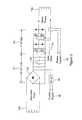
- FIG. 1is a schematic diagram of a fault tolerant electric drive system according to an embodiment of the invention
- FIG. 2is a schematic diagram of a bridge controller circuit forming part of the system of FIG. 1 ;
- FIG. 3is a schematic diagram of a power bridge drive forming another part of the system of FIG. 1 .
- the drive system shown in the accompanying drawingscomprises an alternator 10 arranged to supply electrical power via a motor controller 12 to an electric motor 14 .
- the alternator 10is a multiphase alternator, having n phases, denoted by ⁇ 1 , ⁇ 2 , ⁇ 3 , . . . up to ⁇ n respectively, and each phase ⁇ n of the alternator 10 is electrically connected to a corresponding phase of the motor 14 via an independent phase drive 16 of the motor controller 12 .
- Each phase drive 16 of the motor controller 12comprises an AC/AC convertor arranged to convert the input AC waveform from the alternator phase to an arbitrary AC output waveform supplied to the motor phase.
- Independent electric drive phasesare thereby defined comprising an alternator phase, and its corresponding motor controller phase drive 16 and an associated motor phase.
- Each motor controller phase drive 16comprises a phase controller 18 (see FIG. 2 ) and a power bridge 20 (see FIG. 3 ), the phase controller 18 controlling the current provided to its associated motor phase 14 , via the power bridge 20 , which rectifies and filters the current from the corresponding phase of the alternator 10 .
- a fault tolerant electric driveis thereby created which can continue to operate after the loss of any complete electric drive phase.
- the failure of any single alternator winding, phase drive or motor windingwill result in the loss of just a single electric drive phase, the remaining phases being able to continue to operate independently of the failed phase.
- the electric drivemay be provided with an arbitrary number of electric drive phases. Preferably, four electric drive phases are provided, and the electric drive is specified such that it may continue to function by providing sufficient torque/power/speed with the loss of a single complete electric drive phase. Whilst an arrangement with four phases is described, it will be appreciated that the invention is not restricted in this regard, and arrangements having greater, or fewer, phases are possible without departing from the scope of the invention.
- the fault tolerant electric drive systemis illustrated driving the main fuel pump 22 of a gas turbine aero-engine 24 .
- Such enginesare obviously required to operate with a high degree of reliability, and the main fuel pump 22 thereof must be similarly reliable.
- the engine 24drives the alternator 10 via a mechanical gearbox, at a speed which is proportional to the engine operating speed.
- the electric motor 14is mechanically coupled to the main fuel pump 22 by a drive shaft 26 .
- the main fuel pump 22provides fuel to the engine 24 via a fuel metering valve 28 .
- the nature and function of the metering valve 28will be understood by one skilled in the art and so it will not be described herein in further detail.
- the electric drive systemis controlled by motor speed commands that originate from an engine controller 30 , which is in turn responsive to the pilot's controls 32 .
- the engine controller 30further receives information from a number of sensors (not shown) sensitive to a range of parameters associated with the engine 24 , and also serves to control the operation of the metering valve 28 .
- each phase controller 18 of each motor control phase drive 16may be controlled by commands from the engine controller 30 that are transmitted to the phase controller 18 via a multiplexed bus.
- a dual redundant multiplexed serial buswith first and second command channels 50 , 51 from the engine controller 30 , is shown.
- Each of the command channels 50 , 51is further connected to the other phase controllers 18 of the electric drive system.
- the commands for the electric drive systemare passed to all phase controllers 18 so that the correct sequencing of power phase current to the motor phases can be scheduled accordingly.
- each of the phase controllers 18may include a further data bus that enables data to be shared between the phase controllers 18 , for instance for fault monitoring and accommodation purposes and/or for performance optimisation of the electrical drive scheme.
- Each phase controller 18controls the current provided to its associated motor winding by gate drive signals 55 , which are provided to the power bridge 20 of each motor control phase drive 16 .
- Each phase controller 18receives, from the power bridge 20 of the same phase drive 18 , a regulated power supply 56 , DC link voltage input 52 and a current feedback input 53 .
- a rotor position input 54is provided to each phase controller 18 from a sensor on the rotor of the motor 14 . The form and function of this sensor is well known to those skilled in the art.
- the phase controller 18 for each independent electric drive phase ⁇ 1 to ⁇ nschedules power using its associated power bridge drive circuit according to the current demand, rotor position and DC link voltage.
- the power bridge 20 of each phase drive 16comprises an AC-DC link 61 , and a bridge circuit 62 .
- the AC-DC link 61rectifies and filters the AC power received from an alternator winding 10 a .
- the AC-DC link 61comprises a diode bridge rectifier 60 and smoothing capacitors 63 , the output from which is a substantially DC voltage which is unregulated, and approximately proportional to the rotational speed of the alternator 10 .
- the output from the AC-DC link 61feeds directly into the bridge circuit 62 , which schedules power to a motor winding 14 a that corresponds to the alternator winding 10 a .
- the bridge circuit 62is a pulse width modulation inverter with a standard H-bridge topology, and is controlled by gate drive signals 55 from the phase controller 18 .
- the form and function of the AC-DC link 61 and bridge circuit 62will be understood by those skilled in the art and so will not be described further.
- the power bridge 20includes a current monitoring loop which provides phase current feedback 53 to the phase controller 18 .
- a further DC-DC convertor/regulator stage 64may conveniently be included in the power bridge 20 , to provide a regulated power supply 56 to the phase controller 18 .
- Each alternator winding 10 a and its associated phase drive 16 and motor winding 14 ais independent of other power sources, and therefore filtering and control of electrical power supply distortion is only necessary to meet the requirements of the associated phase drive bridge circuit 62 .
- the alternator speed and power ratingis arranged such that the motor 14 will generate the required fuel flow to the engine 24 across the complete operating range of the engine and for all worst case operating conditions.
- the embodiment of the invention described hereinbeforeprovides a fault tolerant electric drive system that is capable of continuing to operate after the loss of a single alternator winding using only four winding phases on both the motor and alternator.
- Known, prior art systems employing a conventional 3-phase motor with dual redundancy in the alternatorwould require an alternator with 6 winding phases (as disclosed in U.S. Pat. No. 7,583,063) to achieve this.
- the use of conventional motor and alternator arrangementsalso reduces the degree of isolation that can be achieved between motor phases and between alternator phases making it more difficult to isolate faulty windings and associated power drive circuits under fault conditions.
- the arrangement disclosed hereincan tolerate any single electrical fault, including any single fault in the phase controller 18 or phase bridge 20 of the phase drives 16 . Furthermore, any faults that occur can be accommodated almost seamlessly, without a large and/or rapid dip in electric motor power drive to the main fuel pump 22 (and the concomitant risk of flameout in aero-engine applications).
- the independence between the phase windingsresult in full electrical isolation between phase windings, for example, allowing shorted windings to be disconnected without impairing electric motor drive performance. No externally sourced power and associated cables are required (for example from the aircraft), thus also removing any need for bulky EMI/filtering components.
- each of the AC-DC links and bridge circuitsneed only be rated to accommodate full phase power, rather than full motor power.
Landscapes
- Engineering & Computer Science (AREA)
- Mechanical Engineering (AREA)
- General Engineering & Computer Science (AREA)
- Power Engineering (AREA)
- Control Of Ac Motors In General (AREA)
- Hybrid Electric Vehicles (AREA)
- Protection Of Generators And Motors (AREA)
- Control Of Electric Motors In General (AREA)
Abstract
Description
Claims (13)
Applications Claiming Priority (2)
| Application Number | Priority Date | Filing Date | Title |
|---|---|---|---|
| GBGB1200803.3AGB201200803D0 (en) | 2012-01-18 | 2012-01-18 | Fault tolerant electric drive system |
| GB1200803.3 | 2012-01-18 |
Publications (2)
| Publication Number | Publication Date |
|---|---|
| US20130181687A1 US20130181687A1 (en) | 2013-07-18 |
| US8823332B2true US8823332B2 (en) | 2014-09-02 |
Family
ID=45814170
Family Applications (1)
| Application Number | Title | Priority Date | Filing Date |
|---|---|---|---|
| US13/738,427Active2033-01-11US8823332B2 (en) | 2012-01-18 | 2013-01-10 | Fault tolerant electric drive system |
Country Status (3)
| Country | Link |
|---|---|
| US (1) | US8823332B2 (en) |
| EP (1) | EP2617998B1 (en) |
| GB (1) | GB201200803D0 (en) |
Cited By (3)
| Publication number | Priority date | Publication date | Assignee | Title |
|---|---|---|---|---|
| EP3832827A1 (en) | 2019-12-06 | 2021-06-09 | Rolls-Royce plc | Electrical systems |
| EP3832872A1 (en) | 2019-12-06 | 2021-06-09 | Rolls-Royce plc | Electrical systems |
| US12015365B2 (en) | 2019-08-26 | 2024-06-18 | Moog Inc. | Fault tolerant actuator assembly |
Families Citing this family (12)
| Publication number | Priority date | Publication date | Assignee | Title |
|---|---|---|---|---|
| GB201306565D0 (en) | 2013-04-11 | 2013-05-22 | Rolls Royce Plc | Aircraft Electrical System Operating Method |
| US9382011B2 (en)* | 2014-04-10 | 2016-07-05 | Pratt & Whitney Canada Corp. | Multiple aircraft engine control system and method of communicating data therein |
| GB201418685D0 (en)* | 2014-10-21 | 2014-12-03 | Rolls Royce Plc | Gas turbine engine fuel system |
| GB2544097B (en)* | 2015-11-06 | 2017-11-15 | J And M Ferranti Tech Ltd | Electrical drive system |
| JP7027808B2 (en)* | 2016-11-11 | 2022-03-02 | 株式会社デンソー | Rotating electric machine control device and electric power steering device using this |
| CN108923694B (en)* | 2018-09-19 | 2025-03-25 | 无锡赛盈动力科技有限公司 | A motor drive system |
| CN110320799B (en)* | 2019-06-13 | 2021-05-07 | 大连理工大学 | Undisturbed cut-in fault-tolerant control method for faults of aircraft engine actuator |
| GB201913016D0 (en) | 2019-09-10 | 2019-10-23 | Rolls Royce Plc | Elctrical systems |
| GB201913017D0 (en)* | 2019-09-10 | 2019-10-23 | Rolls Royce Plc | Electrical system |
| GB201913015D0 (en) | 2019-09-10 | 2019-10-23 | Rolls Royce Plc | electrical systems |
| CN111852604B (en)* | 2020-07-29 | 2021-08-31 | 奇瑞汽车股份有限公司 | Electric phaser control method and system |
| GB202314033D0 (en) | 2023-09-14 | 2023-11-01 | Rolls Royce Plc | Electric drive apparatus |
Citations (23)
| Publication number | Priority date | Publication date | Assignee | Title |
|---|---|---|---|---|
| US4654572A (en)* | 1984-05-04 | 1987-03-31 | Kabushiki Kaisha Toshiba | Load-commutated inverter for operating synchronous motor |
| JPH03261399A (en)* | 1990-03-12 | 1991-11-21 | Tokyo Electric Power Co Inc:The | Operation control method of variable speed pumped storage power generation system |
| US5708576A (en) | 1996-07-10 | 1998-01-13 | Sundstrand Corporation | Fault tolerant power converter |
| US5937829A (en) | 1996-03-13 | 1999-08-17 | Kokusan Denki Co., Ltd. | Fuel pump drive apparatus for fuel injection equipment for internal combustion engine |
| US6005362A (en)* | 1998-02-13 | 1999-12-21 | The Texas A&M University Systems | Method and system for ride-through of an adjustable speed drive for voltage sags and short-term power interruption |
| US6163129A (en)* | 1999-03-11 | 2000-12-19 | Eaton Corporation | Method of controlling the starting, stopping and speed of an AC induction motor |
| US6445966B1 (en)* | 1999-03-11 | 2002-09-03 | Eaton Corporation | Data interface module for motor control system |
| US6971373B2 (en) | 2002-02-09 | 2005-12-06 | Goodrich Control Systems Limited | Control system |
| US20070073445A1 (en)* | 2005-09-27 | 2007-03-29 | Gamesa Eolica, S.A. | Method for operation of a converter system |
| US20070133235A1 (en)* | 2005-12-14 | 2007-06-14 | Toshiba Mitsubishi-Electric Industrial Systems Corporation | Power conversion apparatus |
| US20070236186A1 (en)* | 2004-04-23 | 2007-10-11 | Patterson Stanley C | Fault tolerant architecture for permanent magnet starter generator subsystem |
| US20080106100A1 (en)* | 2006-11-06 | 2008-05-08 | Abb Oy | Method and arrangement in wind power plant |
| US20080297088A1 (en)* | 2006-01-17 | 2008-12-04 | Abb Schweiz Ag | Fuel/electric drive system |
| US20090212568A1 (en)* | 2008-02-27 | 2009-08-27 | Abb Schweiz Ag | Energy system |
| US7583063B2 (en) | 2003-05-27 | 2009-09-01 | Pratt & Whitney Canada Corp. | Architecture for electric machine |
| US7928592B2 (en)* | 2008-06-30 | 2011-04-19 | General Electric Company | Wind turbine with parallel converters utilizing a plurality of isolated generator windings |
| US7944068B2 (en)* | 2008-06-30 | 2011-05-17 | General Electric Company | Optimizing converter protection for wind turbine generators |
| US8115444B2 (en)* | 2006-05-31 | 2012-02-14 | Honeywell International, Inc. | Common mode filter for motor controllers |
| US8209107B2 (en) | 2008-01-23 | 2012-06-26 | Hamilton Sundstrand Corporation | Electric motor for fuel pump with improved shutdown features |
| US20120217921A1 (en)* | 2011-02-24 | 2012-08-30 | Long Wu | Method and system for evaluating electrical connections between an motor controller and motor |
| US20130106256A1 (en)* | 2010-07-13 | 2013-05-02 | Nissan Motor Co., Ltd. | Power conversion system |
| US8553432B2 (en)* | 2009-06-30 | 2013-10-08 | Vacon Oyj | Power transmission method and power transmission apparatus |
| US8587240B2 (en)* | 2011-07-20 | 2013-11-19 | Eaton Corporation | Operationally dependent filtering for soft starter current measurements |
Family Cites Families (2)
| Publication number | Priority date | Publication date | Assignee | Title |
|---|---|---|---|---|
| DE102006056855A1 (en)* | 2006-12-01 | 2008-06-05 | Robert Bosch Gmbh | Electronic drive system for an aggregate of a vehicle |
| DE102009045049A1 (en)* | 2009-09-28 | 2011-03-31 | Robert Bosch Gmbh | Electric feed pump and method for driving an electric feed pump |
- 2012
- 2012-01-18GBGBGB1200803.3Apatent/GB201200803D0/ennot_activeCeased
- 2013
- 2013-01-08EPEP13150510.9Apatent/EP2617998B1/enactiveActive
- 2013-01-10USUS13/738,427patent/US8823332B2/enactiveActive
Patent Citations (23)
| Publication number | Priority date | Publication date | Assignee | Title |
|---|---|---|---|---|
| US4654572A (en)* | 1984-05-04 | 1987-03-31 | Kabushiki Kaisha Toshiba | Load-commutated inverter for operating synchronous motor |
| JPH03261399A (en)* | 1990-03-12 | 1991-11-21 | Tokyo Electric Power Co Inc:The | Operation control method of variable speed pumped storage power generation system |
| US5937829A (en) | 1996-03-13 | 1999-08-17 | Kokusan Denki Co., Ltd. | Fuel pump drive apparatus for fuel injection equipment for internal combustion engine |
| US5708576A (en) | 1996-07-10 | 1998-01-13 | Sundstrand Corporation | Fault tolerant power converter |
| US6005362A (en)* | 1998-02-13 | 1999-12-21 | The Texas A&M University Systems | Method and system for ride-through of an adjustable speed drive for voltage sags and short-term power interruption |
| US6163129A (en)* | 1999-03-11 | 2000-12-19 | Eaton Corporation | Method of controlling the starting, stopping and speed of an AC induction motor |
| US6445966B1 (en)* | 1999-03-11 | 2002-09-03 | Eaton Corporation | Data interface module for motor control system |
| US6971373B2 (en) | 2002-02-09 | 2005-12-06 | Goodrich Control Systems Limited | Control system |
| US7583063B2 (en) | 2003-05-27 | 2009-09-01 | Pratt & Whitney Canada Corp. | Architecture for electric machine |
| US20070236186A1 (en)* | 2004-04-23 | 2007-10-11 | Patterson Stanley C | Fault tolerant architecture for permanent magnet starter generator subsystem |
| US20070073445A1 (en)* | 2005-09-27 | 2007-03-29 | Gamesa Eolica, S.A. | Method for operation of a converter system |
| US20070133235A1 (en)* | 2005-12-14 | 2007-06-14 | Toshiba Mitsubishi-Electric Industrial Systems Corporation | Power conversion apparatus |
| US20080297088A1 (en)* | 2006-01-17 | 2008-12-04 | Abb Schweiz Ag | Fuel/electric drive system |
| US8115444B2 (en)* | 2006-05-31 | 2012-02-14 | Honeywell International, Inc. | Common mode filter for motor controllers |
| US20080106100A1 (en)* | 2006-11-06 | 2008-05-08 | Abb Oy | Method and arrangement in wind power plant |
| US8209107B2 (en) | 2008-01-23 | 2012-06-26 | Hamilton Sundstrand Corporation | Electric motor for fuel pump with improved shutdown features |
| US20090212568A1 (en)* | 2008-02-27 | 2009-08-27 | Abb Schweiz Ag | Energy system |
| US7944068B2 (en)* | 2008-06-30 | 2011-05-17 | General Electric Company | Optimizing converter protection for wind turbine generators |
| US7928592B2 (en)* | 2008-06-30 | 2011-04-19 | General Electric Company | Wind turbine with parallel converters utilizing a plurality of isolated generator windings |
| US8553432B2 (en)* | 2009-06-30 | 2013-10-08 | Vacon Oyj | Power transmission method and power transmission apparatus |
| US20130106256A1 (en)* | 2010-07-13 | 2013-05-02 | Nissan Motor Co., Ltd. | Power conversion system |
| US20120217921A1 (en)* | 2011-02-24 | 2012-08-30 | Long Wu | Method and system for evaluating electrical connections between an motor controller and motor |
| US8587240B2 (en)* | 2011-07-20 | 2013-11-19 | Eaton Corporation | Operationally dependent filtering for soft starter current measurements |
Non-Patent Citations (1)
| Title |
|---|
| Apr. 27, 2012 Search Report issued in British Application No. 1200803.3. |
Cited By (6)
| Publication number | Priority date | Publication date | Assignee | Title |
|---|---|---|---|---|
| US12015365B2 (en) | 2019-08-26 | 2024-06-18 | Moog Inc. | Fault tolerant actuator assembly |
| EP3832827A1 (en) | 2019-12-06 | 2021-06-09 | Rolls-Royce plc | Electrical systems |
| EP3832872A1 (en) | 2019-12-06 | 2021-06-09 | Rolls-Royce plc | Electrical systems |
| US11271487B2 (en) | 2019-12-06 | 2022-03-08 | Rolls-Royce Plc | Electrical systems |
| US11680529B2 (en) | 2019-12-06 | 2023-06-20 | Rolls-Royce Plc | Electrical systems |
| US12221928B2 (en) | 2019-12-06 | 2025-02-11 | Rolls-Royce Plc | Electrical systems |
Also Published As
| Publication number | Publication date |
|---|---|
| EP2617998B1 (en) | 2019-07-03 |
| EP2617998A2 (en) | 2013-07-24 |
| GB201200803D0 (en) | 2012-02-29 |
| EP2617998A3 (en) | 2018-02-07 |
| US20130181687A1 (en) | 2013-07-18 |
Similar Documents
| Publication | Publication Date | Title |
|---|---|---|
| US8823332B2 (en) | Fault tolerant electric drive system | |
| CN107979116B (en) | Method for distributing power in a power system architecture | |
| US11608184B2 (en) | Hybrid propulsion system for multi-rotor rotary wing aircraft, comprising improved DC/AC conversion means | |
| US4967096A (en) | Cross-start bus configuration for a variable speed constant frequency electric power system | |
| CN107848631B (en) | System for providing kinetic energy for a drive system of an aircraft | |
| RU2416871C2 (en) | Power and control system of electric equipment of aircraft engine, and its instrumentation | |
| EP3304674B1 (en) | Aircraft dc power distribution systems and methods | |
| US9991719B2 (en) | Systems and methods for reducing circulating current and phase to phase imbalance in a parallel modular converter system | |
| US7952316B2 (en) | Variable frequency reduced speed variation electric drive | |
| US7064526B2 (en) | Fault tolerant architecture for permanent magnet starter generator subsystem | |
| US9257838B2 (en) | Circuit and method for allocating power among generators | |
| US9143029B2 (en) | System and method for power distribution | |
| US9302636B2 (en) | Electrical system for an aircraft | |
| SE520333C2 (en) | Electric power system and method of controlling electric power | |
| JP2015047934A (en) | Electric actuator drive device for aircraft | |
| EP3767821A1 (en) | Fault-tolerant electrical drive | |
| CN109565275B (en) | Power distribution system and method | |
| US10658959B2 (en) | Power supply system with first and second AC voltage generators and respective 6-pulse rectifier units | |
| Fabri et al. | Fault-tolerant design of motor-drives for high reliability applications | |
| CN113825701A (en) | Method for controlling an electric power supply network of an aircraft | |
| US9771164B2 (en) | Electric system architecture included in a more-electric engine (MEE) system | |
| US11520361B2 (en) | Control for a target common bus voltage | |
| RU2496209C1 (en) | Standby method of frequency converters in system of electric actuators of circulating pumps of power facility | |
| EP3695506B1 (en) | Textile machine | |
| CN119995434A (en) | A dual-redundancy matrix motor system and fault-tolerant control method |
Legal Events
| Date | Code | Title | Description |
|---|---|---|---|
| AS | Assignment | Owner name:ROLLS-ROYCE ENGINE CONTROL SYSTEMS LIMITED, UNITED Free format text:ASSIGNMENT OF ASSIGNORS INTEREST;ASSIGNOR:SMOUT, PETER DOUGLAS;REEL/FRAME:030331/0702 Effective date:20130422 | |
| AS | Assignment | Owner name:ROLLS-ROYCE ENGINE CONTROL SYSTEMS LIMITED, UNITED Free format text:ASSIGNMENT OF ASSIGNORS INTEREST;ASSIGNOR:SMOUT, PETER DOUGLAS;REEL/FRAME:030451/0523 Effective date:20130422 | |
| XAS | Not any more in us assignment database | Free format text:ASSIGNMENT OF ASSIGNORS INTEREST;ASSIGNOR:SMOUT, PETER DOUGLAS;REEL/FRAME:030451/0523 | |
| AS | Assignment | Owner name:ROLLS-ROYCE CONTROLS AND DATA SERVICES LIMITED, UN Free format text:CHANGE OF NAME;ASSIGNOR:ROLLS-ROYCE ENGINE CONTROL SYSTEMS LTD.;REEL/FRAME:032255/0305 Effective date:20140102 | |
| STCF | Information on status: patent grant | Free format text:PATENTED CASE | |
| AS | Assignment | Owner name:ROLLS-ROYCE PLC, UNITED KINGDOM Free format text:ASSIGNMENT OF ASSIGNORS INTEREST;ASSIGNOR:ROLLS-ROYCE CONTROLS AND DATA SERVICES LIMITED;REEL/FRAME:040722/0838 Effective date:20161104 | |
| MAFP | Maintenance fee payment | Free format text:PAYMENT OF MAINTENANCE FEE, 4TH YEAR, LARGE ENTITY (ORIGINAL EVENT CODE: M1551) Year of fee payment:4 | |
| MAFP | Maintenance fee payment | Free format text:PAYMENT OF MAINTENANCE FEE, 8TH YEAR, LARGE ENTITY (ORIGINAL EVENT CODE: M1552); ENTITY STATUS OF PATENT OWNER: LARGE ENTITY Year of fee payment:8 |