US8821812B2 - Method and means for creating fluid transport - Google Patents
Method and means for creating fluid transportDownload PDFInfo
- Publication number
- US8821812B2 US8821812B2US11/471,061US47106106AUS8821812B2US 8821812 B2US8821812 B2US 8821812B2US 47106106 AUS47106106 AUS 47106106AUS 8821812 B2US8821812 B2US 8821812B2
- Authority
- US
- United States
- Prior art keywords
- fluid
- fluid passage
- projections
- absorbing
- absorbing zone
- Prior art date
- Legal status (The legal status is an assumption and is not a legal conclusion. Google has not performed a legal analysis and makes no representation as to the accuracy of the status listed.)
- Active, expires
Links
Images


Classifications
- B—PERFORMING OPERATIONS; TRANSPORTING
- B01—PHYSICAL OR CHEMICAL PROCESSES OR APPARATUS IN GENERAL
- B01L—CHEMICAL OR PHYSICAL LABORATORY APPARATUS FOR GENERAL USE
- B01L3/00—Containers or dishes for laboratory use, e.g. laboratory glassware; Droppers
- B01L3/50—Containers for the purpose of retaining a material to be analysed, e.g. test tubes
- B01L3/502—Containers for the purpose of retaining a material to be analysed, e.g. test tubes with fluid transport, e.g. in multi-compartment structures
- B01L3/5023—Containers for the purpose of retaining a material to be analysed, e.g. test tubes with fluid transport, e.g. in multi-compartment structures with a sample being transported to, and subsequently stored in an absorbent for analysis
- B—PERFORMING OPERATIONS; TRANSPORTING
- B01—PHYSICAL OR CHEMICAL PROCESSES OR APPARATUS IN GENERAL
- B01L—CHEMICAL OR PHYSICAL LABORATORY APPARATUS FOR GENERAL USE
- B01L3/00—Containers or dishes for laboratory use, e.g. laboratory glassware; Droppers
- B01L3/50—Containers for the purpose of retaining a material to be analysed, e.g. test tubes
- B01L3/502—Containers for the purpose of retaining a material to be analysed, e.g. test tubes with fluid transport, e.g. in multi-compartment structures
- B01L3/5025—Containers for the purpose of retaining a material to be analysed, e.g. test tubes with fluid transport, e.g. in multi-compartment structures for parallel transport of multiple samples
- G—PHYSICS
- G01—MEASURING; TESTING
- G01N—INVESTIGATING OR ANALYSING MATERIALS BY DETERMINING THEIR CHEMICAL OR PHYSICAL PROPERTIES
- G01N33/00—Investigating or analysing materials by specific methods not covered by groups G01N1/00 - G01N31/00
- G01N33/48—Biological material, e.g. blood, urine; Haemocytometers
- G01N33/50—Chemical analysis of biological material, e.g. blood, urine; Testing involving biospecific ligand binding methods; Immunological testing
- G01N33/53—Immunoassay; Biospecific binding assay; Materials therefor
- G01N33/558—Immunoassay; Biospecific binding assay; Materials therefor using diffusion or migration of antigen or antibody
- B—PERFORMING OPERATIONS; TRANSPORTING
- B01—PHYSICAL OR CHEMICAL PROCESSES OR APPARATUS IN GENERAL
- B01L—CHEMICAL OR PHYSICAL LABORATORY APPARATUS FOR GENERAL USE
- B01L3/00—Containers or dishes for laboratory use, e.g. laboratory glassware; Droppers
- B01L3/50—Containers for the purpose of retaining a material to be analysed, e.g. test tubes
- B01L3/502—Containers for the purpose of retaining a material to be analysed, e.g. test tubes with fluid transport, e.g. in multi-compartment structures
- B01L3/5027—Containers for the purpose of retaining a material to be analysed, e.g. test tubes with fluid transport, e.g. in multi-compartment structures by integrated microfluidic structures, i.e. dimensions of channels and chambers are such that surface tension forces are important, e.g. lab-on-a-chip
- B01L3/502746—Containers for the purpose of retaining a material to be analysed, e.g. test tubes with fluid transport, e.g. in multi-compartment structures by integrated microfluidic structures, i.e. dimensions of channels and chambers are such that surface tension forces are important, e.g. lab-on-a-chip characterised by the means for controlling flow resistance, e.g. flow controllers, baffles
- B—PERFORMING OPERATIONS; TRANSPORTING
- B01—PHYSICAL OR CHEMICAL PROCESSES OR APPARATUS IN GENERAL
- B01L—CHEMICAL OR PHYSICAL LABORATORY APPARATUS FOR GENERAL USE
- B01L2300/00—Additional constructional details
- B01L2300/08—Geometry, shape and general structure
- B01L2300/0809—Geometry, shape and general structure rectangular shaped
- B01L2300/0816—Cards, e.g. flat sample carriers usually with flow in two horizontal directions
- B—PERFORMING OPERATIONS; TRANSPORTING
- B01—PHYSICAL OR CHEMICAL PROCESSES OR APPARATUS IN GENERAL
- B01L—CHEMICAL OR PHYSICAL LABORATORY APPARATUS FOR GENERAL USE
- B01L2300/00—Additional constructional details
- B01L2300/08—Geometry, shape and general structure
- B01L2300/0887—Laminated structure
- B—PERFORMING OPERATIONS; TRANSPORTING
- B01—PHYSICAL OR CHEMICAL PROCESSES OR APPARATUS IN GENERAL
- B01L—CHEMICAL OR PHYSICAL LABORATORY APPARATUS FOR GENERAL USE
- B01L2300/00—Additional constructional details
- B01L2300/08—Geometry, shape and general structure
- B01L2300/089—Virtual walls for guiding liquids
- B—PERFORMING OPERATIONS; TRANSPORTING
- B01—PHYSICAL OR CHEMICAL PROCESSES OR APPARATUS IN GENERAL
- B01L—CHEMICAL OR PHYSICAL LABORATORY APPARATUS FOR GENERAL USE
- B01L2300/00—Additional constructional details
- B01L2300/16—Surface properties and coatings
- B01L2300/161—Control and use of surface tension forces, e.g. hydrophobic, hydrophilic
- B—PERFORMING OPERATIONS; TRANSPORTING
- B01—PHYSICAL OR CHEMICAL PROCESSES OR APPARATUS IN GENERAL
- B01L—CHEMICAL OR PHYSICAL LABORATORY APPARATUS FOR GENERAL USE
- B01L2400/00—Moving or stopping fluids
- B01L2400/04—Moving fluids with specific forces or mechanical means
- B01L2400/0403—Moving fluids with specific forces or mechanical means specific forces
- B01L2400/0406—Moving fluids with specific forces or mechanical means specific forces capillary forces
- B—PERFORMING OPERATIONS; TRANSPORTING
- B01—PHYSICAL OR CHEMICAL PROCESSES OR APPARATUS IN GENERAL
- B01L—CHEMICAL OR PHYSICAL LABORATORY APPARATUS FOR GENERAL USE
- B01L2400/00—Moving or stopping fluids
- B01L2400/08—Regulating or influencing the flow resistance
- B01L2400/084—Passive control of flow resistance
- B01L2400/086—Passive control of flow resistance using baffles or other fixed flow obstructions
- Y—GENERAL TAGGING OF NEW TECHNOLOGICAL DEVELOPMENTS; GENERAL TAGGING OF CROSS-SECTIONAL TECHNOLOGIES SPANNING OVER SEVERAL SECTIONS OF THE IPC; TECHNICAL SUBJECTS COVERED BY FORMER USPC CROSS-REFERENCE ART COLLECTIONS [XRACs] AND DIGESTS
- Y10—TECHNICAL SUBJECTS COVERED BY FORMER USPC
- Y10T—TECHNICAL SUBJECTS COVERED BY FORMER US CLASSIFICATION
- Y10T436/00—Chemistry: analytical and immunological testing
- Y10T436/25—Chemistry: analytical and immunological testing including sample preparation
- Y10T436/2575—Volumetric liquid transfer
Definitions
- the present inventionrelates to the field of analytical and diagnostic tests, and in particular to a method and means for establishing or maintaining fluid transport in various devices, including carriers and substrates used in such tests.
- Such testscan be divided into two groups: “one-step tests” where a reaction takes place on a substrate after the addition of sample, and the result is detected as a change of one or more properties of said substrate; and “two-step tests”, where the sample is followed by the addition of a detection conjugate, leading to a specific reaction resulting in a detectable signal.
- the detection conjugate and possible other reagentsis pre-dispensed or integrated in the device, setting aside the need for separate addition of reagents by the user.
- the most common type of disposable assay deviceconsists of a zone or area for receiving the sample, a reaction zone, and optionally a transport or incubation zone connecting the receiving and reaction zone, respectively.
- These assay devicesare known as immunochromatography assay devices or simply referred to as strip tests. They employ a porous material, such as nitrocellulose, defining a fluid passage capable of supporting capillary flow.
- the sample-receiving zonefrequently consists of a more porous material, capable of absorbing the sample, and, when the separation of blood cells is desired, effective to trap the red blood cells.
- fibrous materialssuch as paper, fleece, gel or tissue, comprised e.g. of cellulose, nitrocellulose, wool, glass fibre, asbestos, synthetic fibers, polymers, etc.
- the transport or incubation zonecommonly consists of the same or similar materials, often with different porosity than that of the sample-receiving zone.
- the reaction zonewhich may be integrated with the incubation zone, or constituting the most distal part thereof, commonly consists of similar, absorbing fibrous materials, such as nitrocellulose, or any of the above listed materials.
- the porous material/-sis/are assembled on a carrier, such as a strip of thermoplastic material, paper, cardboard or the like.
- a covercan be provided, said cover having at least one aperture for receiving the sample, and an aperture or a transparent area for reading the result of the assay.
- Nitrocellulose materialsare also frequently used as the matrix constituting the transport or reaction zone, connecting the receiving zone and the reaction zone.
- a significant disadvantage with nitrocelluloseis its high non-specific binding of proteins and other bio-molecules. Present test strips however often handle a surplus of sample, reducing the influence of this binding.
- Another disadvantage of nitrocelluloseis its variable quality, both with regard to chemical and physical properties. It is in any case desirable to minimize the sample volume, in line with the tendency to miniaturize the entire test, including minimizing the amounts of reagents, without compromising accuracy and reliability.
- WO01/27627is representative for the technical background, disclosing an assay device for quantification or detection of the presence or absence of an analyte in a liquid sample, comprising a molding permanently or removably attached to a substantially planar plate such that a part of said molding forms a capillary chamber between said plate and the said molding, the device further comprising a chamber into which a test sample and/or reagent can be introduced and further comprising a chamber capable of accommodating an absorbing pad, wherein the said chamber into which a test sample and said chamber capable of holding an absorbing pad are in lateral flow contact via the said capillary chamber.
- U.S. Pat. No. 6,436,722describes a device and method for integrated diagnostics with multiple independent fluid passages, and an absorbing block providing sufficient capillarity to pull the reagents into said absorbing and sustaining a separate second fluid passage that flows in a second direction from a first fluid passage.
- the absorbing blockis stated to be capable of accommodating a volume of liquid in excess of the total sample volume and the total volume of all other liquid reagents.
- Embodiments of the present inventionare directed to devices including at least one fluid passage for fluid transport, having a first end and a second end; and an absorbing zone specifically adapted to establish, maintain and/or meter fluid transport through or along said at least one fluid passage, wherein said absorbing zone comprises a non-porous substrate having a substrate surface, said zone having projections substantially perpendicular to said surface, and said projections having a height (H), diameter (D) and a distance or distances between the projections (t 1 , t 2 ) such, that lateral capillary flow of said fluid in said zone is achieved.
- Other embodimentsconcern methods for handling fluid transport in or along at least one fluid passage on or in a substrate, wherein the fluid transport in said passage is established and/or maintained and/or metered by an absorbing zone, arranged in fluid contact with said passage, and said absorbing zone comprising an zone made of a non-porous substrate, said zone having projections substantially perpendicular to said surface, and said projections having a height (H), diameter (D) and a distance or distances between the projections (t 1 , t 2 ) such, that lateral capillary flow of said fluid on said zone is achieved.
- an absorbing zonearranged in fluid contact with said passage, and said absorbing zone comprising an zone made of a non-porous substrate, said zone having projections substantially perpendicular to said surface, and said projections having a height (H), diameter (D) and a distance or distances between the projections (t 1 , t 2 ) such, that lateral capillary flow of said fluid on said zone is achieved.
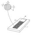
- FIG. 1shows schematically a device with parallel fluid passages according to an embodiment of the invention
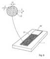
- FIG. 2shows schematically a perspective view of another device according to an embodiment of the invention
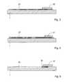
- FIG. 3shows a side view of a device according to an embodiment of the invention
- FIG. 4shows a side view of another embodiment of the invention.
- FIG. 5shows a side view of yet another embodiment
- FIGS. 6 a and 6 bshow schematic cross sections of the device according to two different embodiments
- FIG. 7shows a side view of another embodiment
- FIG. 8shows a perspective view of the embodiment of FIG. 7 ;
- FIG. 9shows a detail illustrating how the height (H), diameter (D) and a distance or distances between the projections (t 1 , t 2 ) can be measured.
- samplehere means a volume of a liquid, solution or suspension, intended to be subjected to qualitative or quantitative determination of any of its properties, such as the presence or absence of a component, the concentration of a component, etc.
- the samplemay be a sample taken from an organism, such as a mammal, preferably a human; or from the biosphere, such as a water sample, or an effluent; or from an technical, chemical or biological process, such as a process of manufacturing, e.g. the production of medicaments, food, feed, or the purification of drinking water or the treatment of waste effluents.
- the samplemay be subjected to qualitative or quantitative determination as such, or after suitable pre-treatment, such as homogenization, sonication, filtering, sedimentation, centrifugation, heat-treatment etc.
- Typical samples in the context of the present inventionare body fluids such as blood, plasma, serum, lymph, urine, saliva, semen, amniotic fluid, gastric fluid, phlegm, sputum, mucus, tears etc.; environmental fluids such as surface water, ground water, sludge etc.; and process fluids such as milk, whey, broth, nutrient solutions, cell culture medium, etc.
- body fluidssuch as blood, plasma, serum, lymph, urine, saliva, semen, amniotic fluid, gastric fluid, phlegm, sputum, mucus, tears etc.
- environmental fluidssuch as surface water, ground water, sludge etc.
- process fluidssuch as milk, whey, broth, nutrient solutions, cell culture medium, etc.
- the determination based on lateral flow of a sample and the interaction of components present in the sample with reagents present in the device and detection of such interactionmay be for any purpose, such as diagnostic, environmental, quality control, regulatory, forensic or research purposes.
- Such testsare often referred to as chromatography assays, or lateral flow assays, as in e.g. immunochromatography assays.
- diagnostic determinationsinclude, but are not limited to, the determination of analytes, also called markers, specific for different disorders, e.g. chronic metabolic disorders, such as blood glucose, blood ketones, urine glucose (diabetes), blood cholesterol (atherosclerosis, obesitas, etc); markers of other specific diseases, e.g. acute diseases, such as coronary infarct markers (e.g. troponin-T), markers of thyroid function (e.g. determination of thyroid stimulating hormone (TSH)), markers of viral infections (the use of lateral flow immunoassays for the detection of specific viral antibodies); etc.
- analytesalso called markers
- markersspecific for different disorders
- chronic metabolic disorderssuch as blood glucose, blood ketones, urine glucose (diabetes), blood cholesterol (atherosclerosis, obesitas, etc
- markers of other specific diseasese.g. acute diseases, such as coronary infarct markers (e.g. troponin-T), markers of thyroid function (e.g. determination of
- pregnancy testsdetermination of i.a. human chorionic gonadotropin (hCG)
- ovulation testsdetermination of i.a. luteneizing hormone (LH)
- fertility testsdetermination of i.a. follicle-stimulating hormone (FSH)
- Yet another important fieldis that of drug tests, for easy and rapid detection of drugs and drug metabolites indicating drug abuse; such as the determination of specific drugs and drug metabolites (e.g. THC) in urine samples etc.
- drugs and drug metabolitese.g. THC
- analyteis used as a synonym of the term “marker” and intended to encompass any substance that is measured quantitatively or qualitatively.
- zonezone
- areaarea
- sitesite
- reactionis used to define any reaction, which takes place between components of a sample and at least one reagent or reagents on or in said substrate, or between two or more components present in said sample.
- reactionis in particular used to define the reaction, taking place between an analyte and a reagent as part of the qualitative or quantitative determination of said analyte.
- substratehere means the carrier or matrix to which a sample is added, and on or in which the determination is performed, or where the reaction between analyte and reagent takes place.
- the term “chemical functionality”comprises any chemical compound or moiety necessary for conducting or facilitating the assay.
- One group of chemical compounds, with particular relevance in the present inventionare compounds or components exhibiting specific affinity to, or capability of binding or interacting with, one or more components in the sample.
- Red blood cell separating agentsconstitute an illustrative example. Such agents may be any substance capable of aggregating or binding red blood cells.
- biological functionalitycomprises all biological interactions between a component in a sample and a reagent on or in the substrate, such as catalysis, binding, internalization, activation, or other bio-specific interaction.
- Suitable reagentsinclude, but are not limited to, antibodies, antibody fragments and derivates, single chain antibodies, lectines, DNA, aptamers, etc., including other polymers or molecules with binding capacity.
- Such reagentscan be identified by a person skilled in the art, following the choice of the component to be separated, using standard experimentation, e.g. screening methods and chemical libraries.
- the term “physical functionality” herecomprises functionalities involved in reactions and interactions other than those that are mainly chemical or biological. Examples include diameter, height, shape, cross section, surface topography and surface patterns, the number of projections per unit area, wetting behavior of the surface of said projections, or a combination thereof, and/or other functionalities influencing the flow, retention, adhesion or rejection of components of the sample.
- hydrophilic and hydrophobicas in hydrophilic or hydrophobic compounds, hydrophilic or hydrophobic interactions etc., have the meaning generally understood by a person skilled in the art, and corresponding to that used in generally recognized textbooks.
- a device for handling fluidsincluding at least one fluid passage for fluid transport, and an absorbing zone for establishing and/or maintaining fluid transport through or along said at least one fluid passage, wherein said absorbing zone comprises an zone made of a non-porous substrate, said zone having projections substantially perpendicular to said surface, and said projections having a height (H), diameter (D) and a distance or distances between the projections (t 1 , t 2 ) such, that lateral capillary flow of said fluid in said zone is achieved.
- the projectionsmay be given a desired chemical, biological or physical functionality, e.g. by modifying the surface of said projections.
- Said deviceis preferably a disposable assay device or a part of such device, such as a diagnostic or analytic assay device.
- Said at least one fluid passagemay be any fluid passage, capable of establishing fluid connection between the location where sample is added, thorough a reaction zone and optional incubation zone(-s), to an absorbing zone.
- the samplecan flow along one fluid passage, or be diverted into two or more, parallel fluid passages. Alternatively, several samples are added to two or more, parallel fluid passages. Similarly, said fluid passages may be continuous or intermittent, the latter meaning that the fluid passage is broken by valves, time gates or locks, regulating the flow velocity, volume or timing of the flow.
- said at least one fluid passageis a passage supporting capillary flow.
- passages supporting capillary floware open or closed capillaries, grooves, channels, wicks, membranes, filters, gels or the like.
- the fluid passagepreferably incorporates or consists partially or entirely of an open lateral fluid passage supported by substantially perpendicular projections, such as the micropillars disclosed in WO 03/103835, by the same applicant.
- Said projections or micropillarsare preferably made of a non-porous substrate, and form projections substantially perpendicular to said surface, said projections having a height (H), diameter (D) and a distance or distances between the projections (t 1 , t 2 ) such, that lateral capillary flow of said fluid in said zone is achieved.
- the projectionsmay be given a desired chemical, biological or physical functionality, e.g. by modifying the surface of said projections.
- an absorbing materialis deposited on or in said zone.
- Said absorbing materialis chosen among cellulose-containing materials, hygroscopic salts, hydrophilic polymer structures, solid hygroscopic particles, porous particles of cross linked networks of flexible polymer chains, such as porous particles of cross linked dextran or agarose, superabsorbents, absorbing foams, such as polyurethane foams, etc.
- FIGS. 3 , 4 and 5This is schematically illustrated in FIGS. 3 , 4 and 5 .
- a device ( 1 )is shown having a fluid passage ( 27 ), here shown as consisting of substantially perpendicular projections, leading to and in fluid communication with an absorbing pad ( 29 ), paced in fluid contact with the fluid passage.
- the substrate ( 1 )carries a fluid passage ( 27 ), here shown as consisting of substantially perpendicular projections, at the distal portion of which absorbing particles ( 31 ) are disposed between the perpendicular projections.
- a fluid passage ( 27 )here shown as consisting of substantially perpendicular projections, at the distal portion of which absorbing particles ( 31 ) are disposed between the perpendicular projections.
- FIG. 5is shown a particular embodiment where on a substrate ( 1 ) a fluid passage ( 33 ) is provided in the form of a groove or channel in the surface of said substrate, where in the distal part of said channel, an area ( 35 ) of projections are provided, said projections forming a transition between said channel and an absorbing zone ( 37 ) in fluid communication with said channel via said projections.
- This embodimenthas the advantage of ensuring good contact between the fluid in the channel or groove, and the absorbing zone, provided on the projections.
- Superabsorbents or superabsorbing polymerssuch as polyacrylate crystals and gels, are well known to a skilled person, and commercially available (e.g. DRYTECH®, The Dow Chemical Company, USA).
- FIG. 2shows a perspective view of a device ( 1 ) having three fluid passages ( 11 , 13 , and 15 ) each in fluid connection with a separate absorbing zone ( 17 , 19 , 21 ).
- the third fluid passage ( 15 )is shown as a groove in the surface of the substrate ( 1 ) leading to the corresponding, third absorbing zone ( 25 ).
- the third fluid passageas such does not support capillary flow.
- the first absorbing zone ( 17 )comprises an absorbing pad ( 23 ) attached to, and in fluid connection to the zone ( 17 ).
- the second absorbing zone ( 19 )comprises an absorbing material, deposited between the substantially perpendicular projections of said zone.
- the third absorbing zone ( 21 )comprises foam, deposited on and between the substantially perpendicular projections of said zone.
- FIG. 6 ashows a cross section of an embodiment where the fluid passage comprising substantially perpendicular projections ( 39 ) is situated in a channel in a substrate so, that the bottom or “floor” of the channel is lower than the general surface ( 43 ) of the substrate. It is preferred that the top of the projections is level with said surface ( 43 ) in order to simplify production and provide protection for the perpendicular projections.
- FIG. 6 bshows a related embodiment where a cover or foil 45 is placed on the top of the perpendicular projections. This serves, inter alia, to accurately limit the volume defined by the projections. It can also be used to modify, preferably enhance the absorption capacity or rate of absorption of the absorption zone, e.g. by influencing the hydrophobic properties of the zone.
- a detail viewshows how the above height (H), diameter (D) and a distance or distances between the projections (t 1 , t 2 ) is measured.
- the micropillars or projectionshave a height in the interval of about 15 to about 150 ⁇ m, preferably about 30 to about 100 ⁇ m, a diameter of about 10 to about 160 ⁇ m, preferably 20 to about 80 ⁇ m, and a distance or distances between the projections of about 5 to about 200 ⁇ m, preferably 10 to about 100 ⁇ m from each other.
- the flow channelmay have a length of about 5 to about 500 mm, preferably about 10 to about 100 mm, and a width of about 1 to about 30 mm, preferably about 2 to about 10 mm.
- a device according to an embodiment of the inventiondoes not necessarily have to have a uniform area of micropillars, but that the dimensions, shape and a distance or distances between the projections of the micropillars may vary in the device. Likewise, the shape and dimensions of the fluid passage may vary.
- said at least one fluid passageis a passage, which as such does not support capillary flow.
- the main examples of such passagesare open or closed passages of a diameter so large, that capillary action do not take place.
- a passage of this kindis filled with liquid, only when an excess of liquid is added, by the action of gravity, centrifugation, pumping or other external influence.
- such a passage not capable of supporting capillary flowcan be connected to an absorbing zone, in which case the absorbing zone will establish flow in the passage.
- said zoneis designed so, that the volume drawn by the zone, and made to pass optional incubation zones and a reaction zone, is determined by the volume of said zone, and not by the amount of sample added to the device.
- a device according to the inventioncomprises two or more parallel passages leading to same absorbing zone or to sections of the same zone.
- a device according to this embodimentis particularly suitable for assays where multiple analytes are to be determined in one sample.
- Each fluid passageis provided with its own set of reagents, and a fraction of the sample enters each passage and reacts with the specific reagents deposited or otherwise present in than passage.
- FIG. 1schematically shows an embodiment comprising a substrate ( 1 ) having three fluid passages ( 3 , 5 , and 7 ) each in fluid connection with an absorbing zone ( 9 ) here illustrated as an area having projections substantially perpendicular to its surface.
- all three fluid passagescomprise projections capable of creating or supporting capillary flow.
- the sampleis added at or near the proximal end of the passages 3 , 5 or 7 , as shown in FIGS. 1 and 2 , or at the left hand end of the passage 27 shown in FIG. 3 , 4 or 5 .
- simultaneous or sequential flow of a fluid in said parallel passagesis achieved by adapting the length, width, depth or other property of said passage.
- a long, meandering passagee.g. as shown in FIGS. 1 and 3 , reference numerals 3 and 11
- a branched passageis used when several reagents are added, or when the same sample is subjected to several analyses.
- One example of an application where a sample is subjected to several analysesis the field of multiplex analyses where the presence and/or activity of various proteins is simultaneously analysed in one sample.
- Bead-based multiplex analysisis well known to a skilled person in this field, and suitable beads with immobilized reactants and detection conjugates are commercially available.
- the bead technologycan be adapted to the device according to the present invention, or the reactants and conjugates immobilized to the substrate used in the inventive device.
- the fluid capacity of the absorbing zoneis at least equal to and preferably at least two times the volume of fluid to be transported. According to a preferred embodiment, the capacity of the absorbing zone determines the amount of sample drawn into the reaction zone, making the device independent of metering of the sample.
- the substantially perpendicular projections according to the embodiments of the inventionare preferably given chemical, biological or physiological properties, including hydrophilic properties, suitable for the assay in question, and suitable for the desired flow rate and capacity.
- coating the projections with dextranis coating the projections with dextran.
- the present inventionalso makes available a method for handling fluid transport in or along at least one fluid passage on a substrate, wherein fluid transport in said passage is established and/or maintained by an absorbing zone, arranged in fluid contact with said passage, and said absorbing zone being an zone made of a non-porous substrate, said zone having projections substantially perpendicular to said surface, and said projections having a height (H), diameter (D) and a distance or distances between the projections (t 1 , t 2 ) such, that lateral capillary flow of said fluid on said zone is achieved.
- said substratepreferably forms at least a part or section of a disposable assay device.
- absorbing materialis deposited on said absorbing zone.
- Said absorbing materialis preferably chosen among cellulose-containing materials, including reinforced cellulose-containing materials, such as cellulose possibly containing glass fibre, nitrocellulose, hygroscopic salts, hydrophilic polymer structures, hydrophilic solid particles, porous particles of cross linked networks of flexible polymer chains, such as porous particles of cross linked dextran or agarose, or cross linked polyacrylamide, superabsorbent materials, polyurethane foams, etc.
- the samplecan be divided between two or more fluid passages, wherein least one fluid passage is a passage supporting capillary flow.
- said at least one fluid passageis a passage which as such does not support capillary flow.
- FIG. 5is equally suitable in place of one or more of the fluid passages ( 3 , 5 , and 7 ) in FIG. 1 or the fluid passages ( 11 , 13 , and 15 ) in FIG. 2 , respectively.
- the different shapes of the fluid passageshere shown as a meandering passage ( 3 , 11 ), an hour-glass shaped passage ( 5 , 13 ), and a substantially straight passage or groove ( 7 , 15 , and 33 ) are illustrative only.
- a fluid passage in a device and method according to the inventionmay also be maze-shaped, branched, interconnected or have other configurations, known to a skilled person within the relevant field.
- the sample or fractions thereofis/are led through parallel passages leading to same absorbing zone or to sections of the same zone.
- simultaneous or sequential flow of a fluid in said parallel passagesis achieved by adapting the length, width, depth or other property of said passage.
- the fluid capacity of the absorbing zoneis at least equal to and preferably at least two times the volume of fluid to be transported.
- the absorption capacity of the absorbing zonedetermines the amount of sample and/or reagent/-s drawn through the fluid passage, including reaction and detection zones, and optional incubation zones. Accordingly, the method includes the accurate metering of sample or reagents, and becomes independent of the amount of sample or reagents added.
- the inventionencompasses any analytical or diagnostic test device comprising a device as defined by the invention and its embodiments, as well as any method comprising the use of such devices or a step as defined herein.
- the embodiments of the inventionmake it possible to replace the conventional absorbing pad with a more compact construction, where the underlying perpendicular projections guarantee the uniformity and reliability of the absorbing zone.
- the perpendicular projectionsguarantee a smooth transition from a fluid passage to the absorbing zone, as well as an even distribution of the sample fluid within said absorption zone.
- the embodimentsmake it possible to accurately measure and regulate the amount of sample and/or reagent drawn through the fluid passage, including the detection zone and optional incubation zones.
- the embodimentsalso simplify the adjustment of the sensitivity of existing tests, and are equally applicable to small or large volumes of sample.
- the use of a foil to cover the absorbing zonenot only helps to very accurately define the volume, it also opens up for modifying the flow velocity. With an identical structure and identical volume, the flow velocity can be adjusted by applying different foils to the structure.
- the embodimentsare particularly suitable for the mass-production of disposable devices having identical flow channels, and highly repeatable features with regard to capacity, flow and reaction times.
- the embodimentsare suitable for being manufactured from well characterized polymeric materials, replacing entirely or in part less well defined fibrous materials.
- the embodimentsfurther make it possible to accurately adjust the absorbing capacity within a large interval, making it possible to tailor disposable analysis devices to various applications.
- Micropillar structures as described in WO 03/103835were produced by Amic AB, Uppsala, Sweden, and used to form both the capillary flow channel and the transition and support for an absorbing zone.
- a positive master including the structures to be testedwas made by etching the structures in silica, and a negative mold as made in nickel, using said silica master.
- Multiple test structureswere manufactured by thermoplastic extrusion against the negative mold, producing the structures on a polypropylene disc, 1 mm thick, which was cut into strips, each having a fluid passage or open flow channel consisting of perpendicular projections or micropillars. The strips had the same dimensions as a typical microscope slide, i.e. 20 ⁇ 76 mm, for practical reasons.
- the micropillarshad the following dimensions: 69 ⁇ m in height, 46 ⁇ m in diameter and placed at approximately 29 ⁇ m distance or distances from each other.
- the flow channelhad a length of 25 mm and a width of 5 mm. The last 5 mm was used as support for the absorbing materials, defining an absorbing zone of about 5 ⁇ 5 mm.
- the steady state flowwas measured by applying 10 ⁇ L of a buffer, composed of 0.25% Triton X-100, 0.5% BSA, 0.3M NaCl, 0.1 M Tris-buffer pH 7.0, in sequence five times. The time for the disappearance of buffer was timed. The last five was used for steady state calculation.
- a buffercomposed of 0.25% Triton X-100, 0.5% BSA, 0.3M NaCl, 0.1 M Tris-buffer pH 7.0
- Polyurethane foamwas cured in situ on the device, in the far end of the flow channel, in an area consisting of perpendicular projections.
- the foamfilled the space between the projections, providing good fluid communication with the remaining flow channel.
- the time for 100 ul to be absorbed by the foamwas measured three times for different samples.
- Table 3showed that a foam can serve as the absorbing zone and that relevant flow is achieved. It is anticipated that optimization of the foam with regard to porosity, curing and other properties, will result in even better flow rates.
- Test stripswere produced, having a fluid passage consisting of or leading into an area of micropillars having the following dimensions: 69 ⁇ m in height, 46 ⁇ m in diameter and placed at approximately 29 ⁇ m distance or distances from each other.
- the flow channelhad a length of about 25 mm and a width of 4 mm.
Landscapes
- Health & Medical Sciences (AREA)
- Chemical & Material Sciences (AREA)
- Hematology (AREA)
- Analytical Chemistry (AREA)
- General Health & Medical Sciences (AREA)
- Chemical Kinetics & Catalysis (AREA)
- Clinical Laboratory Science (AREA)
- Immunology (AREA)
- Life Sciences & Earth Sciences (AREA)
- Engineering & Computer Science (AREA)
- Molecular Biology (AREA)
- Biomedical Technology (AREA)
- Urology & Nephrology (AREA)
- Dispersion Chemistry (AREA)
- Biotechnology (AREA)
- Microbiology (AREA)
- Cell Biology (AREA)
- Food Science & Technology (AREA)
- Medicinal Chemistry (AREA)
- Physics & Mathematics (AREA)
- Biochemistry (AREA)
- General Physics & Mathematics (AREA)
- Pathology (AREA)
- Investigating Or Analysing Biological Materials (AREA)
- Automatic Analysis And Handling Materials Therefor (AREA)
- Absorbent Articles And Supports Therefor (AREA)
Abstract
Description
| TABLE 1 | ||
| Addition | Chip A μL/min | Chip B μL/ |
| 1 | 7.1 | 7.1 |
| 2 | 6.7 | 7.0 |
| 3 | 6.7 | 6.8 |
| 4 | 6.9 | 6.7 |
| 5 | 7.1 | 7.1 |
| TABLE 2 | ||
| Addition | Chip C μL/min | Chip D μL/ |
| 1 | 11 | 11 |
| 2 | 12 | 11 |
| 3 | 12 | 10 |
| 4 | 11 | 11 |
| 5 | 11 | 11 |
| TABLE 3 |
| Obtained results for wicking. The y axis reports |
| time to absorb 100 μL of |
| Sample | time |
| 1 | time 2 | Average | |
| 1.1 | 2.30 | 4.30 | 3.10 | 3.23 |
| 1.2 | 1.30 | 2.00 | 2.00 | 1.77 |
| 2.1 | 5.00 | 5.00 | 5.00 | 5.00 |
| 2.2 | 2.45 | 3.00 | 2.55 | 2.67 |
| 3.1 | 0.22 | 0.23 | 0.30 | 0.25 |
| 3.2 | 0.33 | 0.35 | 0.38 | 0.35 |
| 4.1 | 0.30 | 0.41 | 1.05 | 0.59 |
| 4.2 | 0.35 | 0.35 | 1.05 | 0.58 |
| 5.1 | 1.30 | 1.40 | 1.45 | 1.38 |
| 5.2 | 1.45 | 1.50 | 2.15 | 1.70 |
| 6.1 | 1.55 | 2.10 | 2.15 | 1.93 |
| 6.2 | 1.25 | 2.31 | 2.33 | 1.96 |
| 7.1 | 3.50 | 4.20 | 4.30 | 4.00 |
| 7.2 | 3.40 | 4.25 | — | 2.55 |
| 8.1 | 4.20 | 4.49 | — | 2.90 |
| 8.2 | — | — | — | 0.00 |
| 3.2-A | 2.40 | 3.10 | 3.5 | 3.00 |
| 3.2-B | 0.00 | |||
| 3.2-2 | 0.00 | |||
| TABLE 4 |
| Effect of foil on flow velocity in a micropillar structure |
| Width of fluid passage |
| 4 mm | 2 mm | Total volume | ||
| Flow (μl/min) | Flow (μl/min) | (μl) | ||
| None (open | 11 | 7 | 40 |
| structure) | |||
| 15 | 8 | 30 | |
| Hydrophobic foil | Very slow | Very slow | NA |
Claims (14)
Applications Claiming Priority (3)
| Application Number | Priority Date | Filing Date | Title |
|---|---|---|---|
| SE0501418ASE0501418L (en) | 2005-06-20 | 2005-06-20 | Method and means for effecting liquid transport |
| SE0501418-8 | 2005-06-20 | ||
| SE0501418 | 2005-06-20 |
Publications (2)
| Publication Number | Publication Date |
|---|---|
| US20060285996A1 US20060285996A1 (en) | 2006-12-21 |
| US8821812B2true US8821812B2 (en) | 2014-09-02 |
Family
ID=37054375
Family Applications (1)
| Application Number | Title | Priority Date | Filing Date |
|---|---|---|---|
| US11/471,061Active2028-11-16US8821812B2 (en) | 2005-06-20 | 2006-06-19 | Method and means for creating fluid transport |
Country Status (8)
| Country | Link |
|---|---|
| US (1) | US8821812B2 (en) |
| EP (1) | EP1893337B1 (en) |
| JP (1) | JP5451069B2 (en) |
| CN (1) | CN101203311B (en) |
| AU (1) | AU2006259886B2 (en) |
| BR (1) | BRPI0612248A2 (en) |
| SE (1) | SE0501418L (en) |
| WO (1) | WO2006137785A1 (en) |
Cited By (15)
| Publication number | Priority date | Publication date | Assignee | Title |
|---|---|---|---|---|
| US20080009063A1 (en)* | 2006-07-05 | 2008-01-10 | Teruo Okano | Substrate for cell culture |
| US20140256028A1 (en)* | 2013-03-07 | 2014-09-11 | Kabushiki Kaisha Toshiba | Semiconductor micro-analysis chip and manufacturing method thereof |
| WO2016022655A1 (en) | 2014-08-08 | 2016-02-11 | Ortho-Clinical Diagnostics, Inc. | Lateral-flow assay device with filtration flow control |
| US9316576B2 (en) | 2013-03-07 | 2016-04-19 | Kabushiki Kaisha Toshiba | Sample detection apparatus and detection method |
| US9448153B2 (en) | 2013-03-07 | 2016-09-20 | Kabushiki Kaisha Toshiba | Semiconductor analysis microchip and method of manufacturing the same |
| US9541480B2 (en) | 2011-06-29 | 2017-01-10 | Academia Sinica | Capture, purification, and release of biological substances using a surface coating |
| US10071373B2 (en) | 2014-08-08 | 2018-09-11 | Ortho-Clinical Diagnostics, Inc. | Lateral-flow assay device having flow constrictions |
| US10107726B2 (en) | 2016-03-16 | 2018-10-23 | Cellmax, Ltd. | Collection of suspended cells using a transferable membrane |
| US10112198B2 (en) | 2014-08-26 | 2018-10-30 | Academia Sinica | Collector architecture layout design |
| US10279348B2 (en) | 2013-08-12 | 2019-05-07 | Kabushiki Kaisha Toshiba | Semiconductor micro-analysis chip and method of manufacturing the same |
| US10495644B2 (en) | 2014-04-01 | 2019-12-03 | Academia Sinica | Methods and systems for cancer diagnosis and prognosis |
| US20210170398A1 (en)* | 2018-08-31 | 2021-06-10 | National Institute Of Advanced Industrial Science And Technology | Assay device |
| CN108393105B (en)* | 2018-04-20 | 2023-08-25 | 华南师范大学 | Microfluidic chip, control system and control method thereof |
| US20240001358A1 (en)* | 2021-01-29 | 2024-01-04 | Ortho-Clinical Diagnostics, Inc. | Diagnostic photonic biosensor methods, apparatus, and system |
| WO2024172849A2 (en) | 2022-05-13 | 2024-08-22 | University Of Rochester | Multiplex photonic biosensor apparatus, system, and methods |
Families Citing this family (72)
| Publication number | Priority date | Publication date | Assignee | Title |
|---|---|---|---|---|
| CA2500392C (en) | 2002-09-27 | 2012-11-27 | The General Hospital Corporation | Microfluidic device for cell separation and uses thereof |
| SE0400662D0 (en)* | 2004-03-24 | 2004-03-24 | Aamic Ab | Assay device and method |
| US8921102B2 (en) | 2005-07-29 | 2014-12-30 | Gpb Scientific, Llc | Devices and methods for enrichment and alteration of circulating tumor cells and other particles |
| JP5345136B2 (en)* | 2007-05-23 | 2013-11-20 | ブレイエ・ユニバージテイト・ブリュッセル | Device for distributing sample and carrier liquid to microfabricated separation channels |
| EP2217925A4 (en)* | 2007-12-13 | 2011-01-19 | Beckman Coulter Inc | Device and methods for detecting a target cell |
| US8008032B2 (en)* | 2008-02-25 | 2011-08-30 | Cellective Dx Corporation | Tagged ligands for enrichment of rare analytes from a mixed sample |
| SE533515C2 (en)* | 2008-04-16 | 2010-10-12 | Aamic Ab | Analysis procedure for simultaneous analysis of several analytes |
| US8974749B2 (en)* | 2008-06-16 | 2015-03-10 | Johnson & Johnson Ab | Assay device and method |
| US9285361B2 (en)* | 2008-07-03 | 2016-03-15 | Johnson & Johnson Ab | Method for the analysis of circulating antibodies |
| KR101102532B1 (en)* | 2008-07-10 | 2012-01-03 | 삼성전자주식회사 | A reagent cartridge, a microfluidic device including the reagent cartridge, a manufacturing method thereof, and a sample analysis method using the same |
| EP2336773B1 (en)* | 2008-08-26 | 2013-05-29 | Actherm Inc. | A fluid test chip base plate |
| US20110318822A1 (en)* | 2008-08-29 | 2011-12-29 | Chih-Wei Hsieh | Analytical strip |
| RU2011141298A (en)* | 2009-03-23 | 2013-04-27 | Актерм Инк. | ANALYTICAL STRIP AND METHOD FOR ITS MANUFACTURE |
| JP5816613B2 (en)* | 2009-04-23 | 2015-11-18 | ダブリン シティ ユニバーシティ | Lateral flow analyzer and method for monitoring coagulation |
| EP2270506A3 (en) | 2009-07-02 | 2011-03-09 | Amic AB | Amplified labeled conjugate for use in immunoassays |
| EP2281632B1 (en) | 2009-07-02 | 2013-11-13 | Amic AB | Capillary driven assay device and its manufacture |
| RU2595843C2 (en)* | 2009-10-16 | 2016-08-27 | Омик Аб | Analysis method and device using magnetic particles |
| JP5490492B2 (en)* | 2009-10-30 | 2014-05-14 | 学校法人立命館 | Plasma separator and blood analyzer |
| GB201014316D0 (en) | 2010-08-27 | 2010-10-13 | Univ Dublin City | A agglutination assay method and device |
| US9451913B2 (en)* | 2010-12-10 | 2016-09-27 | Touchtek Labs, Llc | Transdermal sampling and analysis device |
| EP2694967A4 (en)* | 2011-04-06 | 2014-10-29 | Ortho Clinical Diagnostics Inc | Assay device having rhombus-shaped projections |
| JP6177529B2 (en)* | 2012-01-20 | 2017-08-09 | オーソ−クリニカル・ダイアグノスティックス・インコーポレイテッドOrtho−Clinical Diagnostics, Inc. | Assay device with multiple reagent cells |
| EP2618152B1 (en)* | 2012-01-20 | 2015-07-01 | Ortho-Clinical Diagnostics, Inc. | Assay device having controllable sample size |
| JP2013148585A (en)* | 2012-01-20 | 2013-08-01 | Ortho-Clinical Diagnostics Inc | Low volume assay device having increased sensitivity |
| JP6395999B2 (en) | 2012-01-20 | 2018-09-26 | オーソ−クリニカル・ダイアグノスティックス・インコーポレイテッドOrtho−Clinical Diagnostics, Inc. | Controlling fluid flow through an assay device |
| BR102013001328A2 (en) | 2012-01-20 | 2015-05-12 | Ortho Clinical Diagnostics Inc | Teaching device having uniform flow near corners |
| WO2013109821A1 (en) | 2012-01-20 | 2013-07-25 | Ortho-Clinical Diagnostics, Inc. | Assay device having multiplexing |
| CA2818332C (en) | 2012-06-12 | 2021-07-20 | Ortho-Clinical Diagnostics, Inc. | Lateral flow assay devices for use in clinical diagnostic apparatus and configuration of clinical diagnostic apparatus for same |
| EP2888373B1 (en) | 2012-08-21 | 2018-03-14 | Janssen Pharmaceutica NV | Antibodies to aripiprazole and use thereof |
| WO2014031630A2 (en) | 2012-08-21 | 2014-02-27 | Ortho-Clinical Diagnostics, Inc | Antibodies to paliperidone and use thereof |
| EP3462173B1 (en) | 2012-08-21 | 2021-03-31 | Janssen Pharmaceutica NV | Antibodies to risperidone and use thereof |
| CN104736567B (en) | 2012-08-21 | 2019-09-03 | 詹森药业有限公司 | Antibodies to aripiprazole hapten and uses thereof |
| PT2887952T (en) | 2012-08-21 | 2019-08-30 | Janssen Pharmaceutica Nv | Antibodies to olanzapine haptens and use thereof |
| CA2882615C (en) | 2012-08-21 | 2019-07-09 | Ortho-Clinical Diagnostics, Inc. | Antibodies to quetiapine and use thereof |
| CA2882489A1 (en) | 2012-08-21 | 2014-02-27 | Ortho-Clinical Diagnostics, Inc. | Antibodies to paliperidone haptens and use thereof |
| WO2014031662A2 (en) | 2012-08-21 | 2014-02-27 | Ortho-Clinical Diagnostics, Inc | Antibodies to olanzapine and use thereof |
| PL3663317T3 (en) | 2012-08-21 | 2023-06-05 | Janssen Pharmaceutica Nv | Antibodies to quetiapine haptens and use thereof |
| ES2652641T3 (en) | 2012-08-21 | 2018-02-05 | Janssen Pharmaceutica Nv | Haptenosis of aripiprazole and its use in immunoassays |
| CN108517014A (en) | 2012-08-21 | 2018-09-11 | 詹森药业有限公司 | The antibody and application thereof of Risperidone haptens |
| CA3129014A1 (en) | 2012-11-15 | 2014-05-15 | Ortho-Clinical Diagnostics, Inc. | Quality/process control of a lateral flow assay device based on flow monitoring |
| BR112015011040A2 (en) | 2012-11-15 | 2017-07-11 | Ortho Clinical Diagnostics Inc | test calibration using reaction time |
| EP4293357A3 (en) | 2013-02-04 | 2024-03-20 | Epona Biotech Ltd | Device and methods |
| KR20140100843A (en)* | 2013-02-07 | 2014-08-18 | 삼성전자주식회사 | Support for capturing glycated protein in a sample and device and method for measuring the glycated protein using the same |
| CA2841692C (en) | 2013-02-12 | 2023-08-22 | Zhong Ding | Reagent zone deposition pattern |
| JP2014173937A (en)* | 2013-03-07 | 2014-09-22 | Toshiba Corp | Semiconductor micro-analysis chip and analyte flowing method |
| EP2778679B1 (en) | 2013-03-15 | 2017-09-27 | Ortho-Clinical Diagnostics, Inc. | Rotable disk-shaped fluid sample collection device |
| US10898116B2 (en) | 2013-03-15 | 2021-01-26 | Cambridge Medical Technologies LLC | Methods of manufacture to optimize performance of transdermal sampling and analysis device |
| EP2777499B1 (en) | 2013-03-15 | 2015-09-16 | Ortho-Clinical Diagnostics Inc | Rotatable fluid sample collection device |
| DE102013111759A1 (en)* | 2013-10-25 | 2015-04-30 | Bürkert Werke GmbH | Apparatus and method for assaying sample fluid |
| CN105980842B (en) | 2013-12-06 | 2019-12-17 | 奥索临床诊断有限公司 | Assay device with wash port |
| JP6278772B2 (en)* | 2014-03-19 | 2018-02-14 | テルモ株式会社 | Blood glucose measurement chip |
| US9903858B2 (en) | 2014-07-23 | 2018-02-27 | Ortho-Clinical Diagnostics, Inc. | Multiplexing with single sample metering event to increase throughput |
| US10031085B2 (en) | 2014-07-24 | 2018-07-24 | Ortho-Clinical Diagnostics, Inc. | Point of care analytical processing system |
| US10073091B2 (en) | 2014-08-08 | 2018-09-11 | Ortho-Clinical Diagnostics, Inc. | Lateral flow assay device |
| GB2535998A (en) | 2015-02-27 | 2016-09-07 | Intelligent Fingerprinting Ltd | A device for receiving and analysing a sample |
| CN104880562A (en)* | 2015-04-08 | 2015-09-02 | 上海盛复源生物医药有限公司 | L-FABP (Liver-Fatty Acid Binding Protein) rapid detection reagent and preparation method thereof |
| CN104880563A (en)* | 2015-04-08 | 2015-09-02 | 上海盛复源生物医药有限公司 | NGAL rapid detection reagent and preparation method thereof |
| AU2016264112A1 (en) | 2015-05-19 | 2017-11-16 | Ortho-Clinical Diagnostics, Inc. | Method of improving liquid sample flow in assay device |
| MA44056A (en) | 2015-12-17 | 2018-10-24 | Janssen Pharmaceutica Nv | ANTI-RISPERIDONE ANTIBODIES AND THEIR USE |
| EP3390455A1 (en) | 2015-12-17 | 2018-10-24 | Janssen Pharmaceutica NV | Antibodies to quetiapine and use thereof |
| US10656151B2 (en) | 2016-01-29 | 2020-05-19 | Ortho-Clinical Diagnostics, Inc. | Air capillary vent for a lateral flow assay device |
| CN107469478B (en)* | 2016-06-07 | 2023-06-06 | 苏州苏瑞膜纳米科技有限公司 | Fluid treatment device and preparation method thereof |
| CN116747615B (en)* | 2016-06-07 | 2024-09-03 | 苏州苏瑞膜纳米科技有限公司 | Fluid treatment device and preparation process thereof |
| WO2018152496A1 (en) | 2017-02-17 | 2018-08-23 | The Usa, As Represented By The Secretary, Dept. Of Health And Human Services | Compositions and methods for the diagnosis and treatment of zika virus infection |
| EP4230649A3 (en) | 2017-04-25 | 2023-10-25 | The U.S.A. As Represented By The Secretary, Department Of Health And Human Services | Antibodies and methods for the diagnosis and treatment of epstein barr virus infection |
| US11827669B2 (en) | 2017-07-19 | 2023-11-28 | The Usa, As Represented By The Secretary, Dept. Of Health And Human Services | Antibodies and methods for the diagnosis and treatment of hepatitis b virus infection |
| US12084489B2 (en) | 2018-05-02 | 2024-09-10 | The United States Of America, As Represented By The Secretary, Department Of Health And Human Services | Antibodies and methods for the diagnosis, prevention, and treatment of Epstein Barr virus infection |
| GB201902769D0 (en) | 2019-03-01 | 2019-04-17 | Univ Court Of The Univ Of Aberdeen | Antibody molcules and uses thereof |
| US11633129B2 (en) | 2019-04-05 | 2023-04-25 | Cambridge Medical Technologies LLC | Non-invasive transdermal sampling and analysis device incorporating redox cofactors |
| US20220276235A1 (en)* | 2019-07-18 | 2022-09-01 | Essenlix Corporation | Imaging based homogeneous assay |
| US11375931B2 (en) | 2019-08-08 | 2022-07-05 | Cambridge Medical Technologies LLC | Non-invasive transdermal sampling and analysis device incorporating an electrochemical bioassay |
| CN116105967B (en)* | 2023-04-17 | 2023-06-20 | 四川省农业机械研究设计院 | Wind field experiment platform for crop lodging resistance test experiment |
Citations (15)
| Publication number | Priority date | Publication date | Assignee | Title |
|---|---|---|---|---|
| WO1998043739A2 (en) | 1997-03-27 | 1998-10-08 | Biosite Diagnostics Incorporated | Diagnostic devices and apparatus for the controlled movement of reagents without membranes |
| US6143576A (en) | 1992-05-21 | 2000-11-07 | Biosite Diagnostics, Inc. | Non-porous diagnostic devices for the controlled movement of reagents |
| US6150178A (en)* | 1999-03-24 | 2000-11-21 | Avitar, Inc. | Diagnostic testing device |
| WO2001027627A2 (en) | 1999-10-14 | 2001-04-19 | Imperial College Innovations Limited | Assay device |
| US20020004246A1 (en)* | 2000-02-07 | 2002-01-10 | Daniels Robert H. | Immunochromatographic methods for detecting an analyte in a sample which employ semiconductor nanocrystals as detectable labels |
| US6416642B1 (en)* | 1999-01-21 | 2002-07-09 | Caliper Technologies Corp. | Method and apparatus for continuous liquid flow in microscale channels using pressure injection, wicking, and electrokinetic injection |
| US6436722B1 (en) | 2000-04-18 | 2002-08-20 | Idexx Laboratories, Inc. | Device and method for integrated diagnostics with multiple independent flow paths |
| US20030035758A1 (en) | 1996-08-26 | 2003-02-20 | Biosite Incorporated | Devices for incorporating filters for filtering fluid samples |
| WO2003103835A1 (en) | 2002-06-07 | 2003-12-18 | Åmic AB | Micro fluidic structures |
| US20040077103A1 (en) | 1992-05-21 | 2004-04-22 | Biosite, Inc. | Diagnostic devices and apparatus for the controlled movement of reagents without membranes |
| US20040115831A1 (en)* | 2002-04-19 | 2004-06-17 | Meathrel William G. | Diagnostic devices for use in the assaying of biological fluids |
| US20040126767A1 (en) | 2002-12-27 | 2004-07-01 | Biosite Incorporated | Method and system for disease detection using marker combinations |
| US20040142495A1 (en)* | 2002-12-16 | 2004-07-22 | Hartman William G. | Analyte detecting article and method |
| US20040191127A1 (en)* | 2003-03-31 | 2004-09-30 | Avinoam Kornblit | Method and apparatus for controlling the movement of a liquid on a nanostructured or microstructured surface |
| US20050136552A1 (en) | 1992-05-21 | 2005-06-23 | Biosite, Inc. | Diagnostic devices and apparatus for the controlled movement of reagents without membranes |
Family Cites Families (8)
| Publication number | Priority date | Publication date | Assignee | Title |
|---|---|---|---|---|
| US5051237A (en) | 1988-06-23 | 1991-09-24 | P B Diagnostic Systems, Inc. | Liquid transport system |
| US6451264B1 (en)* | 2000-01-28 | 2002-09-17 | Roche Diagnostics Corporation | Fluid flow control in curved capillary channels |
| CA2301451A1 (en)* | 2000-03-20 | 2001-09-21 | Thang T. Pham | Method for analysis of analytes by mass spectrometry |
| JP3584863B2 (en)* | 2000-08-25 | 2004-11-04 | 株式会社島津製作所 | Continuous gas analyzer |
| JP2002196001A (en)* | 2000-09-22 | 2002-07-10 | Shino Test Corp | Measuring apparatus and measuring method for specimen |
| JP3757133B2 (en)* | 2001-06-06 | 2006-03-22 | アドバンテック東洋株式会社 | Underwater sampler |
| JP4199609B2 (en)* | 2002-07-12 | 2008-12-17 | 三菱化学株式会社 | ANALYSIS CHIP, ANALYSIS CHIP UNIT, ANALYSIS DEVICE, AND METHOD FOR PRODUCING ANALYSIS CHIP |
| JP2004325153A (en)* | 2003-04-23 | 2004-11-18 | Aida Eng Ltd | Microchip and its manufacturing method |
- 2005
- 2005-06-20SESE0501418Apatent/SE0501418L/ennot_activeIP Right Cessation
- 2006
- 2006-06-19USUS11/471,061patent/US8821812B2/enactiveActive
- 2006-06-20EPEP06747937.8Apatent/EP1893337B1/enactiveActive
- 2006-06-20WOPCT/SE2006/000745patent/WO2006137785A1/enactiveApplication Filing
- 2006-06-20AUAU2006259886Apatent/AU2006259886B2/ennot_activeCeased
- 2006-06-20CNCN2006800222142Apatent/CN101203311B/ennot_activeExpired - Fee Related
- 2006-06-20JPJP2008518078Apatent/JP5451069B2/ennot_activeExpired - Fee Related
- 2006-06-20BRBRPI0612248-5Apatent/BRPI0612248A2/ennot_activeApplication Discontinuation
Patent Citations (18)
| Publication number | Priority date | Publication date | Assignee | Title |
|---|---|---|---|---|
| US20040077103A1 (en) | 1992-05-21 | 2004-04-22 | Biosite, Inc. | Diagnostic devices and apparatus for the controlled movement of reagents without membranes |
| US6143576A (en) | 1992-05-21 | 2000-11-07 | Biosite Diagnostics, Inc. | Non-porous diagnostic devices for the controlled movement of reagents |
| US6156270A (en) | 1992-05-21 | 2000-12-05 | Biosite Diagnostics, Inc. | Diagnostic devices and apparatus for the controlled movement of reagents without membranes |
| US20050136552A1 (en) | 1992-05-21 | 2005-06-23 | Biosite, Inc. | Diagnostic devices and apparatus for the controlled movement of reagents without membranes |
| US6767510B1 (en) | 1992-05-21 | 2004-07-27 | Biosite, Inc. | Diagnostic devices and apparatus for the controlled movement of reagents without membranes |
| US20030035758A1 (en) | 1996-08-26 | 2003-02-20 | Biosite Incorporated | Devices for incorporating filters for filtering fluid samples |
| WO1998043739A2 (en) | 1997-03-27 | 1998-10-08 | Biosite Diagnostics Incorporated | Diagnostic devices and apparatus for the controlled movement of reagents without membranes |
| US6416642B1 (en)* | 1999-01-21 | 2002-07-09 | Caliper Technologies Corp. | Method and apparatus for continuous liquid flow in microscale channels using pressure injection, wicking, and electrokinetic injection |
| US6150178A (en)* | 1999-03-24 | 2000-11-21 | Avitar, Inc. | Diagnostic testing device |
| WO2001027627A2 (en) | 1999-10-14 | 2001-04-19 | Imperial College Innovations Limited | Assay device |
| US20020004246A1 (en)* | 2000-02-07 | 2002-01-10 | Daniels Robert H. | Immunochromatographic methods for detecting an analyte in a sample which employ semiconductor nanocrystals as detectable labels |
| US6436722B1 (en) | 2000-04-18 | 2002-08-20 | Idexx Laboratories, Inc. | Device and method for integrated diagnostics with multiple independent flow paths |
| US20040115831A1 (en)* | 2002-04-19 | 2004-06-17 | Meathrel William G. | Diagnostic devices for use in the assaying of biological fluids |
| WO2003103835A1 (en) | 2002-06-07 | 2003-12-18 | Åmic AB | Micro fluidic structures |
| US20050042766A1 (en)* | 2002-06-07 | 2005-02-24 | Amic Ab | Micro fluidic structures |
| US20040142495A1 (en)* | 2002-12-16 | 2004-07-22 | Hartman William G. | Analyte detecting article and method |
| US20040126767A1 (en) | 2002-12-27 | 2004-07-01 | Biosite Incorporated | Method and system for disease detection using marker combinations |
| US20040191127A1 (en)* | 2003-03-31 | 2004-09-30 | Avinoam Kornblit | Method and apparatus for controlling the movement of a liquid on a nanostructured or microstructured surface |
Non-Patent Citations (1)
| Title |
|---|
| Supplementary European Search Report for EP Application No. 06 747 937.8; mailed May 7, 2012; 6 pages. |
Cited By (22)
| Publication number | Priority date | Publication date | Assignee | Title |
|---|---|---|---|---|
| US20080009063A1 (en)* | 2006-07-05 | 2008-01-10 | Teruo Okano | Substrate for cell culture |
| US11674958B2 (en) | 2011-06-29 | 2023-06-13 | Academia Sinica | Capture, purification, and release of biological substances using a surface coating |
| US9541480B2 (en) | 2011-06-29 | 2017-01-10 | Academia Sinica | Capture, purification, and release of biological substances using a surface coating |
| US9316576B2 (en) | 2013-03-07 | 2016-04-19 | Kabushiki Kaisha Toshiba | Sample detection apparatus and detection method |
| US9448153B2 (en) | 2013-03-07 | 2016-09-20 | Kabushiki Kaisha Toshiba | Semiconductor analysis microchip and method of manufacturing the same |
| US20140256028A1 (en)* | 2013-03-07 | 2014-09-11 | Kabushiki Kaisha Toshiba | Semiconductor micro-analysis chip and manufacturing method thereof |
| US10279348B2 (en) | 2013-08-12 | 2019-05-07 | Kabushiki Kaisha Toshiba | Semiconductor micro-analysis chip and method of manufacturing the same |
| US10495644B2 (en) | 2014-04-01 | 2019-12-03 | Academia Sinica | Methods and systems for cancer diagnosis and prognosis |
| US10071373B2 (en) | 2014-08-08 | 2018-09-11 | Ortho-Clinical Diagnostics, Inc. | Lateral-flow assay device having flow constrictions |
| WO2016022655A1 (en) | 2014-08-08 | 2016-02-11 | Ortho-Clinical Diagnostics, Inc. | Lateral-flow assay device with filtration flow control |
| US11033896B2 (en) | 2014-08-08 | 2021-06-15 | Ortho-Clinical Diagnostics, Inc. | Lateral-flow assay device with filtration flow control |
| US11260390B2 (en) | 2014-08-08 | 2022-03-01 | Ortho-Clinical Diagnostics, Inc. | Lateral-flow assay device having flow constrictions |
| US11931734B2 (en) | 2014-08-08 | 2024-03-19 | Ortho-Clinical Diagnostics, Inc. | Lateral-flow assay device having flow constrictions |
| US12285755B2 (en) | 2014-08-08 | 2025-04-29 | Ortho-Clinical Diagnostics, Inc. | Lateral-flow assay device with filtration flow control |
| US10112198B2 (en) | 2014-08-26 | 2018-10-30 | Academia Sinica | Collector architecture layout design |
| US10107726B2 (en) | 2016-03-16 | 2018-10-23 | Cellmax, Ltd. | Collection of suspended cells using a transferable membrane |
| US10605708B2 (en) | 2016-03-16 | 2020-03-31 | Cellmax, Ltd | Collection of suspended cells using a transferable membrane |
| CN108393105B (en)* | 2018-04-20 | 2023-08-25 | 华南师范大学 | Microfluidic chip, control system and control method thereof |
| US20210170398A1 (en)* | 2018-08-31 | 2021-06-10 | National Institute Of Advanced Industrial Science And Technology | Assay device |
| US12326445B2 (en)* | 2018-08-31 | 2025-06-10 | National Institute Of Advanced Industrial Science And Technology | Assay device |
| US20240001358A1 (en)* | 2021-01-29 | 2024-01-04 | Ortho-Clinical Diagnostics, Inc. | Diagnostic photonic biosensor methods, apparatus, and system |
| WO2024172849A2 (en) | 2022-05-13 | 2024-08-22 | University Of Rochester | Multiplex photonic biosensor apparatus, system, and methods |
Also Published As
| Publication number | Publication date |
|---|---|
| EP1893337A4 (en) | 2012-06-06 |
| EP1893337B1 (en) | 2018-11-14 |
| JP2008547017A (en) | 2008-12-25 |
| BRPI0612248A2 (en) | 2010-10-26 |
| SE528233C2 (en) | 2006-09-26 |
| US20060285996A1 (en) | 2006-12-21 |
| CN101203311A (en) | 2008-06-18 |
| AU2006259886A1 (en) | 2006-12-28 |
| EP1893337A1 (en) | 2008-03-05 |
| WO2006137785A1 (en) | 2006-12-28 |
| CN101203311B (en) | 2012-10-03 |
| AU2006259886B2 (en) | 2012-12-06 |
| SE0501418L (en) | 2006-09-26 |
| JP5451069B2 (en) | 2014-03-26 |
Similar Documents
| Publication | Publication Date | Title |
|---|---|---|
| US8821812B2 (en) | Method and means for creating fluid transport | |
| US9606112B2 (en) | Assay device and method | |
| EP1768783B1 (en) | Controlled flow assay device and method | |
| US11921107B2 (en) | Assay device having controllable sample size | |
| KR20130085991A (en) | Assay device having uniform flow around corners | |
| KR20130085994A (en) | Assay device with multiple reagent cells | |
| AU2012251951A1 (en) | Method and means for creating fluid transport |
Legal Events
| Date | Code | Title | Description |
|---|---|---|---|
| AS | Assignment | Owner name:AMIC AB, SWEDEN Free format text:ASSIGNMENT OF ASSIGNORS INTEREST;ASSIGNORS:OHMAN, PER OVE;MENDEL-HARTVIG, IB;SIGNING DATES FROM 20060613 TO 20060616;REEL/FRAME:018022/0711 Owner name:AMIC AB, SWEDEN Free format text:ASSIGNMENT OF ASSIGNORS INTEREST;ASSIGNORS:OHMAN, PER OVE;MENDEL-HARTVIG, IB;REEL/FRAME:018022/0711;SIGNING DATES FROM 20060613 TO 20060616 | |
| AS | Assignment | Owner name:BARCLAYS BANK PLC, AS COLLATERAL AGENT, NEW YORK Free format text:SECURITY INTEREST;ASSIGNORS:ORTHO-CLINICAL DIAGNOSTICS, INC;CRIMSON U.S. ASSETS LLC;CRIMSON INTERNATIONAL ASSETS LLC;REEL/FRAME:033276/0104 Effective date:20140630 | |
| AS | Assignment | Owner name:JOHNSON & JOHNSON AB, SWEDEN Free format text:MERGER;ASSIGNOR:AMIC AB;REEL/FRAME:033364/0103 Effective date:20120906 | |
| STCF | Information on status: patent grant | Free format text:PATENTED CASE | |
| FEPP | Fee payment procedure | Free format text:ENTITY STATUS SET TO UNDISCOUNTED (ORIGINAL EVENT CODE: BIG.) | |
| MAFP | Maintenance fee payment | Free format text:PAYMENT OF MAINTENANCE FEE, 4TH YEAR, LARGE ENTITY (ORIGINAL EVENT CODE: M1551) Year of fee payment:4 | |
| AS | Assignment | Owner name:CRIMSON INTERNATIONAL ASSETS LLC, DELAWARE Free format text:ASSIGNMENT OF ASSIGNORS INTEREST;ASSIGNOR:JOHNSON JOHNSON AB;REEL/FRAME:046773/0588 Effective date:20140630 | |
| MAFP | Maintenance fee payment | Free format text:PAYMENT OF MAINTENANCE FEE, 8TH YEAR, LARGE ENTITY (ORIGINAL EVENT CODE: M1552); ENTITY STATUS OF PATENT OWNER: LARGE ENTITY Year of fee payment:8 | |
| AS | Assignment | Owner name:CRIMSON INTERNATIONAL ASSETS LLC, NEW JERSEY Free format text:RELEASE BY SECURED PARTY;ASSIGNOR:BANK OF AMERICA, N.A.;REEL/FRAME:060219/0571 Effective date:20220527 Owner name:CRIMSON U.S. ASSETS LLC, NEW JERSEY Free format text:RELEASE BY SECURED PARTY;ASSIGNOR:BANK OF AMERICA, N.A.;REEL/FRAME:060219/0571 Effective date:20220527 Owner name:ORTHO-CLINICAL DIAGNOSTICS, INC., NEW JERSEY Free format text:RELEASE BY SECURED PARTY;ASSIGNOR:BANK OF AMERICA, N.A.;REEL/FRAME:060219/0571 Effective date:20220527 Owner name:BANK OF AMERICA, N.A., NORTH CAROLINA Free format text:SECURITY AGREEMENT;ASSIGNORS:QUIDEL CORPORATION;BIOHELIX CORPORATION;DIAGNOSTIC HYBRIDS, INC.;AND OTHERS;REEL/FRAME:060220/0711 Effective date:20220527 |