US8821799B2 - Method and system implementing spatially modulated excitation or emission for particle characterization with enhanced sensitivity - Google Patents
Method and system implementing spatially modulated excitation or emission for particle characterization with enhanced sensitivityDownload PDFInfo
- Publication number
- US8821799B2 US8821799B2US11/698,409US69840907AUS8821799B2US 8821799 B2US8821799 B2US 8821799B2US 69840907 AUS69840907 AUS 69840907AUS 8821799 B2US8821799 B2US 8821799B2
- Authority
- US
- United States
- Prior art keywords
- particle
- excitation
- signal
- modulated
- spatially modulated
- Prior art date
- Legal status (The legal status is an assumption and is not a legal conclusion. Google has not performed a legal analysis and makes no representation as to the accuracy of the status listed.)
- Active, expires
Links
Images


Classifications
- G—PHYSICS
- G01—MEASURING; TESTING
- G01N—INVESTIGATING OR ANALYSING MATERIALS BY DETERMINING THEIR CHEMICAL OR PHYSICAL PROPERTIES
- G01N21/00—Investigating or analysing materials by the use of optical means, i.e. using sub-millimetre waves, infrared, visible or ultraviolet light
- G01N21/62—Systems in which the material investigated is excited whereby it emits light or causes a change in wavelength of the incident light
- G01N21/63—Systems in which the material investigated is excited whereby it emits light or causes a change in wavelength of the incident light optically excited
- G01N21/64—Fluorescence; Phosphorescence
- G01N21/6486—Measuring fluorescence of biological material, e.g. DNA, RNA, cells
- G—PHYSICS
- G01—MEASURING; TESTING
- G01N—INVESTIGATING OR ANALYSING MATERIALS BY DETERMINING THEIR CHEMICAL OR PHYSICAL PROPERTIES
- G01N15/00—Investigating characteristics of particles; Investigating permeability, pore-volume or surface-area of porous materials
- G01N15/10—Investigating individual particles
- G01N15/14—Optical investigation techniques, e.g. flow cytometry
- G01N15/1468—Optical investigation techniques, e.g. flow cytometry with spatial resolution of the texture or inner structure of the particle
- G01N15/147—Optical investigation techniques, e.g. flow cytometry with spatial resolution of the texture or inner structure of the particle the analysis being performed on a sample stream
- G—PHYSICS
- G01—MEASURING; TESTING
- G01N—INVESTIGATING OR ANALYSING MATERIALS BY DETERMINING THEIR CHEMICAL OR PHYSICAL PROPERTIES
- G01N15/00—Investigating characteristics of particles; Investigating permeability, pore-volume or surface-area of porous materials
- G01N15/10—Investigating individual particles
- G01N15/14—Optical investigation techniques, e.g. flow cytometry
- G01N15/1425—Optical investigation techniques, e.g. flow cytometry using an analyser being characterised by its control arrangement
- G01N15/1427—Optical investigation techniques, e.g. flow cytometry using an analyser being characterised by its control arrangement with the synchronisation of components, a time gate for operation of components, or suppression of particle coincidences
- G—PHYSICS
- G01—MEASURING; TESTING
- G01N—INVESTIGATING OR ANALYSING MATERIALS BY DETERMINING THEIR CHEMICAL OR PHYSICAL PROPERTIES
- G01N15/00—Investigating characteristics of particles; Investigating permeability, pore-volume or surface-area of porous materials
- G01N15/10—Investigating individual particles
- G01N15/14—Optical investigation techniques, e.g. flow cytometry
- G01N15/1434—Optical arrangements
- G01N2015/1447—Spatial selection
- G—PHYSICS
- G01—MEASURING; TESTING
- G01N—INVESTIGATING OR ANALYSING MATERIALS BY DETERMINING THEIR CHEMICAL OR PHYSICAL PROPERTIES
- G01N15/00—Investigating characteristics of particles; Investigating permeability, pore-volume or surface-area of porous materials
- G01N15/10—Investigating individual particles
- G01N15/14—Optical investigation techniques, e.g. flow cytometry
- G01N15/1434—Optical arrangements
- G01N2015/1454—Optical arrangements using phase shift or interference, e.g. for improving contrast
- Y—GENERAL TAGGING OF NEW TECHNOLOGICAL DEVELOPMENTS; GENERAL TAGGING OF CROSS-SECTIONAL TECHNOLOGIES SPANNING OVER SEVERAL SECTIONS OF THE IPC; TECHNICAL SUBJECTS COVERED BY FORMER USPC CROSS-REFERENCE ART COLLECTIONS [XRACs] AND DIGESTS
- Y10—TECHNICAL SUBJECTS COVERED BY FORMER USPC
- Y10T—TECHNICAL SUBJECTS COVERED BY FORMER US CLASSIFICATION
- Y10T436/00—Chemistry: analytical and immunological testing
- Y10T436/14—Heterocyclic carbon compound [i.e., O, S, N, Se, Te, as only ring hetero atom]
- Y10T436/142222—Hetero-O [e.g., ascorbic acid, etc.]
- Y10T436/143333—Saccharide [e.g., DNA, etc.]
- Y—GENERAL TAGGING OF NEW TECHNOLOGICAL DEVELOPMENTS; GENERAL TAGGING OF CROSS-SECTIONAL TECHNOLOGIES SPANNING OVER SEVERAL SECTIONS OF THE IPC; TECHNICAL SUBJECTS COVERED BY FORMER USPC CROSS-REFERENCE ART COLLECTIONS [XRACs] AND DIGESTS
- Y10—TECHNICAL SUBJECTS COVERED BY FORMER USPC
- Y10T—TECHNICAL SUBJECTS COVERED BY FORMER US CLASSIFICATION
- Y10T436/00—Chemistry: analytical and immunological testing
- Y10T436/17—Nitrogen containing
Definitions
- Methods for particle characterization(which generally relates to detection as well as other useful characterizations such as location/position determination, particle counting and cell sorting) often suffer from a low signal-to-noise ratio (SNR), since the signal obtained from the particle (in general: a small object) is typically weak in comparison to the background. This is particularly true in connection with optical methods of particle characterization.
- SNRsignal-to-noise ratio
- the low signal-to-noise ratiois also particularly noteworthy in cases of detection of individual particles such as a cell, an aerosol, a molecule, a subvolume of liquid which differs from the surrounding liquid or emulsion, or a piece of DNA with dyes or tags at selection positions.
- DNA sequencingis accomplished by splitting a DNA strand into small pieces, separating the pieces with electrophoresis and then elaborately reconstructing the DNA sequence.
- An alternative processhas recently been developed. In this alternative process, certain base sequences are tagged with fluorescent dyes. After stretching (or “linearizing”) the molecule, the DNA strand is moved through a microfluidic channel at a constant speed. A special fluorescence reader with a high spatial resolution (approx. 1 ⁇ m) is used to record the positions of the fluorescent dyes or tags. As a result, an “optical bar code” of the DNA containing the position of the tags is recorded. Therefore, the DNA sequence may be identified.
- Typical distance between the tags along the DNAis several ⁇ m. Consequently, the required spatial resolution is one ⁇ m or better.
- this conceptis demonstrated by using a con-focal microscope, which allows for exciting and also detecting the fluorescence within a very small volume ( ⁇ 1 ⁇ m3).
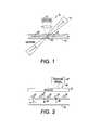
- FIG. 1schematically illustrates a conventional approach for spatially resolved fluorescence excitation.
- a system 10includes a detector 12 , a channel 14 and an excitation light 16 .
- a small volume within the channel 14is excited.
- Lightis collected from the excited volume.
- DNA strings 20 with tagged portions 22run through an excitation area 24 of the channel 14 .
- the positions of the tagsare calculated using a time dependent detector signal.
- the methodcomprises generating a spatially modulated excitation region, creating relative movement between a particle and the excitation region, the particle being excited upon exposure to the excitation region to obtain a time modulated signal, and, recording the modulated signal.
- the excitation regionincludes an excitation pattern.
- the time modulated signalis caused by light emission from the particle.
- the excitation regioncomprises interference stripes.
- the excitation regionis generated by at least one of a shadow mask and a lens array.
- the excitation patternis generated by chemo-luminescence.
- the methodfurther comprises at least one of determining a location of the particle based on the signal, counting particles based on the signal, and sorting particles based on the signal.
- the detectingcomprises detecting with a pixilated detector.
- the particleis a portion of a DNA molecule or a molecule attached to the DNA molecule and the signal is used to determine DNA sequencing.
- the detectingcomprises using a spectrometer to receive the fluorescent spectrum of the fluorescing analyte.
- the generating of the excitation regioncomprises generating a spatially modulated pattern based on at least one of geometry, electric or magnetic field, fluorescence quenching, analyte concentration, density, and acoustic standing wave.
- the generating of the excitation patterncomprises generating a spatially modulated region based on environment.
- the generating, creating and recordingis conducted in two-dimensions to locate the particle.
- a method for characterizing particlescomprises moving a particle within a channel, providing an environment along the channel which causes the particle to create a time modulated signal, and, detecting and evaluating the time modulated signal.
- the environmentcomprises an optical element and the particle emits light detected by the optical element.
- the optical elementis operative to modulate the signal obtained from the particle as a function of a position of a particle.
- the methodfurther comprises moving the optical element.
- the optical elementis one of a shadow mask and a micro-lens array.
- the methodfurther comprises at least one of determining a location of the particle based on the signal, counting particles based on the signal, and sorting particles based on the signal.
- the detectingcomprises detecting with a pixilated detector.
- the particleis a portion of a DNA molecule or a molecule attached to the DNA molecule and the signal is used to determine DNA sequencing.
- the detectingcomprises using a spectrometer to receive a fluorescent spectrum of the particle.
- the optical elementis operative to pattern the light based on at least one of geometry, electric or magnetic field, fluorescence quenching, particle concentration, density, and acoustic standing wave.
- a system for characterizing particlescomprises means for generating a spatially modulated excitation region, means for providing relative movement between a particle and the region, the particle being excited upon exposure to the excitation area to obtain a time modulated signal, means for recording the modulated signal.
- the systemfurther comprises at least one of a means for determining a location of the particle based on the signal a means for counting particles based on the signal, and means for sorting particles based on the signal.
- a system for characterizing particlescomprises a channel, a means for moving a particle within the channel, an environment along the channel operative to cause the particle to create time modulated signal, and, a detection system to record and evaluate the time modulated signal.
- the environmentcomprises an optical element.
- systemfurther comprises an anti-resonant waveguide operative to cause the particle to emit light.
- the systemfurther comprises at least one of a means for determining a location of the fluorescent analyte based on the signal, a means for counting particles based on the signal, and a means for sorting particles based on the signal.
- the environmentallows for a two-dimensional evaluation.
- FIG. 1is a representative view of a prior art system
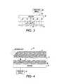
- FIG. 2is a representative view of a presently described embodiment
- FIG. 3is a representative view of a presently described embodiment
- FIG. 4is a representative view of a presently described embodiment
- FIG. 5is a representative view of a presently described embodiment
- FIG. 6is a representative view of a presently described embodiment
- FIG. 7is a representative view of a presently described embodiment
- FIGS. 8( a )-( d )are representative views of presently described embodiments.
- FIG. 9is a flow chart according to the presently described embodiments.
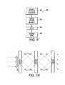
- FIG. 10is a representative view of a presently described embodiment
- FIG. 11is a representative view of a presently described embodiment
- FIG. 12is an illustration of various forms of signals that may be used in connection with the presently described embodiments.
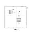
- FIG. 13is a representative view of a presently described embodiment
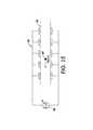
- FIG. 14is a representative view of a presently described embodiment.
- FIG. 15is a representative view of a presently described embodiment.
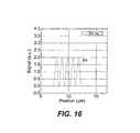
- FIG. 16is a graph illustrating a signal from a particle detected with a system in accordance with some embodiments.
- FIG. 17is a signal from two particles detected with a system in accordance with some embodiments.
- FIG. 18is a signal from two particles where noise is present in the signal
- FIG. 19is a signal used in the presently described embodiments.
- FIG. 20is a signal used in connection with the presently described embodiments.
- FIG. 21is a signal shown in FIG. 19 having applied thereto the presently described embodiments.
- FIG. 22is the signal of FIG. 20 having applied thereto the presently described embodiments
- FIG. 23is a signal used in connection with the presently described embodiments.
- FIG. 24is a signal used in connection with the presently described embodiments.
- FIG. 25is a signal used in connection with the presently described embodiments.
- FIG. 26is a signal used in connection with the presently described embodiments.
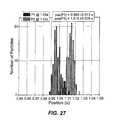
- FIG. 27is a signal used in connection with the presently described embodiments.
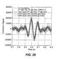
- FIG. 28is a signal used in connection with the presently described embodiments.
- This patent applicationdescribes a method and a system to improve the signal-to-noise ratio during particle characterization by implementing a phase sensitive technique which allows for clearly distinguishing between the signals from the particle and the background.
- the methodis based on the deliberate introduction of controlled relative movement between the particle and the environment.
- the combination of, for example, the moving particle and a conditioned environmentresults in a time modulated signal.
- a monitored responsecomprises a noisy background signal and the modulated signal, with a well defined time dependence attributable to the particle.
- Both hardware and software solutionscan be applied to extract the signal attributed to the particle.
- the signal attributed to the particlecan then be used in characterizing the particle for a variety of different applications, including detection, location/position determination, and cell sorting.
- Various techniquesmay be employed to accomplish these characterizations. It should be noted, however, that one technique for characterization, i.e., determination of particle positions and distances, is described in U.S. application Ser. No. 11/698,338, entitled “Method and System for Evaluation of Signals Received from Spatially Modulated Excitation and Emission to Accurately Determine Particle Positions and Distances,” filed on even date herewith, and may be advantageously implemented along with the presently described embodiments.
- the contemplated signalcan have any shape as a function of time. It is not necessarily periodic. Even a signal modulated randomly is useful, as long as the structure of the signal is known. In this regard, the structure may be known but the signal may not follow an analytic regularity. So, the time periods defining “on” and “off” states for the particle will have a random length. Even where the time dependence of the signal is built into the system, the time dependence of the system can be varied, as long as it is predictable or known.
- signal 12 - 1is a periodic signal.
- Signal 12 - 2is a chirped signal, e.g., a signal that has a linearly increasing frequency.
- a random signal 12 - 3is also shown. It should be appreciated that these signals (as well as others) may be used in connection with the presently described embodiments to achieve the objectives of the presently described embodiments.
- the presently described embodimentsare described for a variety of cases including: (1) a collection of individual moving particles (2) a linearized DNA strand in which the objects of interest are distributed and fixed along the length of the strand i.e., commonly termed DNA sequencing, and (3) a collection of particles potentially fixed on a surface (providing a need, in some applications, for a two-dimensional analysis).
- the particles being detectedmay include cells, aerosols, DNA material pieces of DNA with dyes at selected positions, subvolumes in a liquid which differs from the surrounding liquid or emulsion, droplets, other small volumes of fluid, bubbles, single molecules, agglomerated molecules, molecule clusters, biological cells, viruses, bacteria, proteins, microparticles, nanoparticles, and emulsions.
- a droplet or small volume of fluidmay, for example, include atoms, molecules or other particles that affect refractive index, absorption, or other optical characteristics.
- the objectcould be conveyed in a fluid, such as a liquid, gas, or aerosol, in which case the object may be referred to as being “carried by the fluid.”
- a channelmay be defined in a variety of manners to include not only ones defined by walls, but also ones defined by the flow of particles in, for example, an aerosol stream or the like.
- light emission from these particlesmay result from a variety of sources including fluorescence excitation, elastic and inelastic light scattering, chemo-luminescence or other types of light scattering and reflection techniques. Still further, the light used in these implementations may include a variety of different types of lighting including, ultraviolet, VIS, infrared, near infrared, etc.
- the environments in which this particle characterization process is implementedinclude environments wherein there is a spatially modulated excitation of the particles or a modulation of an emitted light from particles over a detection region. In this regard, the particles may emit a homogeneous excitation that is filtered using, for example, a shadow mask or other optics, which leads to a spatial modulation of the emitted light.
- FIGS. 2-14generally relate to optical cases while FIG. 15 relates to an example non-optical case.
- a channel 34is provided with optical elements 32 for modulating emitted light within a detection region.
- the optical elements 32may take a variety of forms such as lenses, masks or filters.
- a detector 31for detecting the emitted light from the optical elements 32 as a function of time. It should be understood that the detector 31 (as well as other detectors noted herein) may take a variety of forms including photo-diodes, avalanche photo-diodes, photo-multiplier tubes, etc. It should also be appreciated that the detector 31 and optical elements 32 may be combined in a single element or system.
- Lightmay be emitted from particles such as particle 36 and particle 38 that are traveling down the channel 34 . It should be understood that the light emission from the particle may result from the various phenomenon described above. It should also be understood that the relative movement between the particles 36 and 38 and the optical element system 32 , or output modulator, create the modulation desired to be able to appropriately analyze the particles 36 and 38 .
- the spatially modulated opticscreate a time modulated signal in the detector 31 . This signal, which as noted may take a variety of predictable forms, may be analyzed using the processing module 39 for purposes of characterizing the particles.
- the signal generated as a function of timemay take a variety of forms, e.g., periodic, chirped, random . . . etc., as a function of a variety of environmental factors.
- the opticsmay take a form that coincides with the type of signal. So, the optical element structure may resemble that of the signal examples of FIG. 12 .
- the relative movementmay be created by way of the particle moving, the detector/optical elements moving along, for example, the channel or by way of movement of both of these elements. It should be further understood that movement of both of the elements may, in one form, result in movement of each element at different velocities.
- the system 40includes a channel 42 that is provided with regions 44 where particles, such as particles 46 and 48 , are caused to emit light. Regions 44 , as shown, create a modulated excitation area that can be achieved by various methods. These methods include interference, use of shadow masking, use of lens arrays and use of chemo-luminescence and fluorescent quenching. Relative movement between the particle and the excitation area or pattern can be achieved by moving the particle, the excitation pattern or both. As with the previous embodiment, it should be appreciated that movement of both, in one form, would result in movement of each at different speeds.
- the spatially modulated opticscreate a time modulated signal in the detector 41 . This signal, which as noted may take a variety of predictable forms, may be analyzed using the processing module 49 for purposes of characterizing the particles.
- System 50includes a channel 52 and an anti-resonant wave guide 54 .
- the anti-resonant wave guideprovides homogeneous illumination of the channel as the particle travels therethrough.
- Modulationcan be created by mirrors 56 which can be suitably placed inside or outside the channel.
- the spatially modulated opticscreate a time modulated signal in the detector 51 .
- This signalwhich as noted may take a variety of predictable forms, may be analyzed using the processing module 59 for purposes of characterizing the particles.
- the presently described embodimentsprovide for a characterization of particles traveling through other types of medium (e.g., liquid) that is improved by way of modulation.
- the light emitted from particlesis modulated and, in other cases, the modulation occurs by way of modulated excitation of the particles. In both cases, it is the relative movement of the system elements that provides the modulated effect.
- FIG. 11another embodiment is illustrated.
- a system 300positioned near a channel 302 in which a particle 304 is traveling.
- the particle 304is detected by a detector 306 having an optical element 308 positioned thereon operative to produce a spatial pattern.
- the detection of the particleis facilitated by optics 310 , which may take a variety of forms including a lens or lens system.
- the particlelies in an object plane 320 while an image plane 322 is associated with the detector 306 and optical element 308 .
- the particle size, pattern size and spatial resolutionare essentially de-coupled.
- the optics 310serve to magnify (or de-magnify) the particle 304 and conduct the detecting at a location remote from the particle 304 .
- light originating from the particle 304is modulated in the image plane 322 .
- the detector 306is then able to detect the light from the particle 304 in the channel 302 without being positioned on the channel 302 .
- the optical element 308should be in or near the image plane 322 of the optics 310 . In this way, the “optical distance” between the particle 304 and the optical element 308 is minimized.
- the detectoritself can contain optics as well as introduce additional magnification or de-magnification.
- the size of the detectoris a factor in the sampling rate of the system. In some cases it might therefore be preferable to de-magnify the channel on a small and faster detector to gain increased sampling rate.
- the optical elementmay be positioned on the channel itself. If so, the distance between the detector and the optical element would be determined by the channel dimensions.
- a more specific implementation of the presently described embodimentsrelates to DNA sequencing.
- a system 100according to the presently described embodiments is shown.
- the systemincludes a detector 102 , a fluid channel 104 and excitation light 106 having a spatially modulated excitation pattern 108 therewithin.
- the pattern 108aligns with the channel 104 to create a detection region or area 105 .
- the system 100allows for conveyance of, for example, a DNA string 110 having a backbone portion 112 and fluorescent tags, or particles, 114 embedded therein.
- the interference pattern 108is generated by an energy source such as a laser source and has a submicron periodicity perpendicular to particle flow. It should be appreciated that other angles might also be used.
- the fluorescent emissionis modulated according to the speed of the fluorescent particle or tag 114 and the periodicity of the stripe pattern 108 .
- the signal detector 102which records the emission over at least one stripe can be used.
- the detected signalis recorded with a fast detector read-out in order to capture the “blinking” of the fluorescent particle(s) or tags 114 while they are moving through the detection area 105 and, consequently, the excitation pattern 108 .
- a processing module 109may be implemented to analyze the signal for purposes of particle characterization.
- the presently described embodimentsenable fluorescence detection with high signal-to-noise ratio and high spatial resolution, as discussed in the following, without the need of expensive and bulky optics.
- the DNA backbone 112is typically labeled with one type of fluorophore and specific portions of the linearized molecule are labeled with a second type of fluorophore, that is, fluorescent tags 114 .
- FIG. 6illustrates the detection scheme according to the presently described embodiments in more detail. As shown, the fluorescence backbone signal 120 first increases in a step-like function when the uniformly labeled DNA backbone 112 moves into the detection area 105 . Additionally, the backbone signal 120 is superimposed with a sinusoidal signal 122 when one of the tags 114 moves through the excitation pattern 108 . This results in a detected signal 126 .
- FIG. 5only a single detector is shown. However, multiple detectors may be implemented. Also, it should be appreciated that various configurations of detectors may be implemented to realize the presently described embodiments.
- Backbone portions 112 and tagged portions 114are usually labeled with fluorophores emitting at different wavelength bands.
- Appropriate filtersensure that only fluorescence originating from the tags enters detector 202 whereas detector 204 receives light only from the backbone.
- Simple optical componentscan be incorporated to improve wavelength selectivity of the filters. For example, micro-lens arrays can collimate the fluorescent light.
- the filterscan be designed such that they do not only transmit the first wavelength band of interest but also efficiently reflect the second wavelength band of interest onto the opposite detector in order to minimize fluorescent light loss.
- the system 200 of FIG. 7can also be used to measure the fluorescence from different fluorescence tags marking different portions of the DNA simultaneously.
- second stage detectors 206 and 208may likewise be implemented to refine, for example, the DNA analysis that is being conducted. For example, to refine a DNA characterization, fluorescence from differently colored tags marking different portions of a DNA strand may be measured.
- Stripesare usually generated by creating a standing wave in one dimension.
- a mirror 80creates a standing wave in the channel direction.
- Different directionsalso may be used.
- the distance d between two adjacent interference maximacan be calculated as follows:
- ⁇indicates the relative angle between the two interfering beams and ⁇ is the wavelength, with d varying between ⁇ /2 and infinity dependent upon ⁇ .
- the excitation patterncan be directed onto the channel “from outside” through the top or bottom surface or “in plane” from the side.
- the detection componentsare most probably attached from top and/or bottom it is favorable to use “in-plane” excitation in order to reduce the amount of excitation light that reach the detectors.
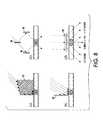
- FIG. 8( a )-( d )can be realized in the microfluidic chamber by using waveguide structures and mirrors based on total internal reflection (TIR) on substrate/air interfaces.
- FIG. 8( a )illustrates a prism interferometer.
- FIG. 8( b )illustrates a Lloyd interferometer using the mirror 80 .
- FIG. 8( c )illustrates a Michelson interferometer using a beam splitter 84 and mirrors 86 .
- a periodically moving stagee.g., a speaker or piezo element.
- This techniquecan also be applied to address stationary particles. This allows improvement in the sensitivity of the system by using a double modulation technique.
- FIG. 8( d )illustrates a phase mask interferometer 88 .
- a favorable approachis based on phase masks or transmission gratings, as shown in FIG. 8( d ).
- Light scattered into the ⁇ 1st orderinterferes with light scattered in +1st order.
- the gratingscan be designed such that scattering into 0 and 2nd order is minimized.
- Most techniques shown in this sectioncan be designed such that multiple-fluidic-channel excitation is feasible.
- FIG. 10illustrates another design for illuminating parallel channels which is based on phase masks, such as phase mask 90 .
- the methods according to the presently described embodimentsinclude, in at least one form, the basic undertakings of creating a spatially modulated environment, detecting light emitted from the excited particles in the environment, and generating a time modulated signal based on the detecting.
- the generated signalis used to determine positions of the excited particles, e.g. tags in the DNA strand.
- the systemin one form, is provided with a processing module (e.g., processing modules 39 , 49 , 59 and 109 ) to allow for the generation of the spatially modulated signal and any subsequent processing such as determining the relative positions of particles.
- This processing modulemay be incorporated within the detector or implemented apart from the detector. Along these lines, it should be understood that the methods described herein may be implemented using a variety of hardware configurations and software techniques. For example, the contemplated processing module may include software routines that will allow for signal generation and location determination.
- an excitation patternis generated (at 502 ).
- the excitationmay be homogeneous with a patterned output generated by a shadow mask or the like (e.g., a modulator).
- relative movement between, for example, a fluorescing analyte and the excitation patternis provided (at 504 ). Any emitted or scattered light as function of time is then detected (at 506 ).
- a spatially modulated signal based on the detectingis then generated (at 508 ).
- the spatially modulated signalcan then be used, in one form, to determine the relative positions of fluorescing particles such as tags in a DNA strand.
- the modulated excitationnot only ensures high spatial resolution but at the same time enables a method to increase the signal-to-noise ratio.
- Most sources which contribute to the background signale.g., the backbone signal, fluorescence excited by scattered excitation, or all other DC-like sources
- a correlation techniquewhich allows the read-out to be only sensitive to the modulated signal originating from the moving tags.
- the excitation sourcecan be modulated with a higher frequency in order to separate fluorescence light from other background sources (e.g., room light).
- the frequencyhas to be chosen high enough to ensure that the light source is switched on and off several times while a tag is passing one interference fringe.
- a modulation frequency of 100 kHzfulfills that criterion and is easily feasible. As much faster detectors are available, it is even possible to apply conventional lock-in or correlation techniques to sample more accurately at 100 kHz, e.g., by modulating the excitation light with 1 MHz in phase with a detector.
- the detector signalin order to determine the precise position of the tags on the DNA, the detector signal (no matter how obtained) is de-convoluted.
- the signalis recorded with a high sampling rate.
- the time informationis thus converted to position information using the velocity of the DNA string.
- the velocity of the DNA stringis extracted from the periodicity of the time dependent fluorescence signal or can be measured by other well known techniques.
- the analysiscan be done, using a variety of signal processing algorithms including Fourier-Transformation analysis or Least-Square fitting techniques. Some of these techniques are described in greater detail in, for example, U.S. application Ser. No.
- An exemplary procedure for the signal processingis as follows:
- the time-dependent signal S(t)corresponding, for example, to the spatial modulation of the excited tags (shown in various forms in FIGS. 16-18 ), is multiplied with a test function P(t), which is restricted to a small window in time of the signal, and subsequently integrated.
- the test windowis then shifted by one time interval and processed in the same way again. This is done for all time intervals.
- the following equationdescribes how the resulting correlation signal L(t) is calculated.
- FIG. 19shows the resulting signal L(t) without noise whereas FIG. 20 shows the same evaluation with noise added to the original signal.
- the correlation signalis further processed.
- the analysiscan be done, using a variety of signal processing algorithms, including Fourier-Transformation analysis or Least-Square fitting techniques. The latter one has been used in the following example.
- a triangular function f(t)is fitted to the correlation signal.
- two particlesare within the detection area at the same time.
- the correlation signalis thus fitted with the sum of two triangles.
- the position (t 1 , t 2 ) of the two trianglesis varied independently in order to minimize the deviations between the correlation signal and the sum of the triangle functions.
- tis varied in order to minimize ⁇ 2 , where i is the number of a particle with
- ⁇ 2⁇ t ⁇ ( L ⁇ ( t ) - ⁇ i ⁇ ⁇ f ⁇ ( t - t i ) ) 2
- FIGS. 21 and 22shows the two triangles as well as the sum of both triangles for the case without and with noise, respectively.
- the position of the tip of the trianglesidentifies the original position of the fluorescent tags.
- the following tableindicates the real positions of the fluorescent tags as well as the deconvoluted positions for both discussed cases. Without noise, the positions received from the deconvoluted Signal match perfectly with the real positions of the fluorescent tags. In the noisy case, the deviation is larger but still smaller than 1, meaning that in this case the position error is still smaller that the periodic constant from the excitation pattern. This is sufficient for most applications.
- the location of a fluorescence particlecan be extracted precisely from the time-dependence of the fluorescence signal (even in the case of extremely high noise). Also, the positions of several fluorescent particles which are within the interference pattern simultaneously can be determined.
- the above techniquescan be modified to be implemented in a variety of different circumstances.
- One such modificationmay involve generalizing the above technique to evaluate the position of a single particle that may not produce a periodic signal, but another signal with known time dependence.
- a chirped signalis used.
- the chirped signalis a non-periodic signal where the duration of each detection of light (e.g. 29 peaks) from the particle decreases by a factor of two over the entire signal length T (e.g. 3 seconds).
- Te.g. 3 seconds
- the frequency of the signalincreases from a minimum frequency f min linearly to a maximum frequency f max .
- An ideal signal of this typeis plotted in FIG. 23 .
- the particleis detected by an appropriate sensor and the resultant signal is recorded, as shown in FIG. 23 .
- the resultant signalis recorded, as shown in FIG. 23 .
- many different systemscan be used to accomplish this recording, including those systems described in U.S. Publication No. 2008/0181827.
- the resultant signalmay be generated by virtue of a variety of different patterns and/or associated architectures and/or techniques.
- the overall patternhas a size larger than the particle size.
- the minimum spacing of the features of the patterne.g. the stripes of a pattern
- Patterns of such configurationare advantageous to gain a relatively high spatial resolution, so that information may be had from the resulting signal that will be useful for determining precise locations and positions.
- determining that a particle is simply within a patternis insufficient—determining precise locations and positions is an objective. For consistency, to determine a particle position with respect to other particles, or the environment, measurements of time are taken as the particle exits the pattern. Of course, other conventions may be used.
- the generalized technique described hereafterhas, in at least one form, two basic components: 1) determining the existence and estimated position of a particle and 2) determining particle position to a higher accuracy by applying a correlation technique to the measured signal. It should be understood that exercising the first component of the technique reduces computational effort and, thus, saves system resources.
- a sliding integralis calculated to determine the existence and estimated position of a particle.
- the sliding integralsums the measured signal S(t) over a defined time period T (e.g. 3 seconds). This calculation is accomplished using the following:
- I ⁇ ( t )⁇ t - T t ⁇ S ⁇ ( ⁇ ) ⁇ ⁇ d ⁇
- This positioning algorithmincludes routines that will fit a triangle to the sliding integral. Fitting the triangle allows for determining a rough estimate of the particle position. To more accurately determine the position, a correlation signal is then calculated using the following:
- P( ⁇ )is a test signal which is identical to the expected signal which, in this example, is the chirped signal as described above;
- Tis the length of the chirped test signal P( ⁇ )
- FIG. 25illustrates that the derivative of the correlation signal is then taken. Note that 30 simulations are illustrated as opposed to a single measured and single ideal correlation signal, as in FIG. 24 .
- the maximum and minimum in the proximitye.g. +/ ⁇ 0.5 seconds
- the maximum difference between the maximum and minimum for all pairs of neighboring maxima and minimais then determined (in this example, one has to compare a maximum and its neighboring minimum to the right).
- the particle positioncan then be determined based on the zero transition of the determined maximum difference (zero transition method). In this regard, translation from the zero transition to a position is accomplished as a function of the flow speed of the fluid in the channel. In cases where the fluid is not flowing, the speed of the detector or the microscopic slide, for example, is used to translate the zero transition point to a position.
- the above techniqueis applied in one form to determine the position of a single particle.
- the number of particles within a sliding integral windowis evaluated. To do so, the slope of the triangle sides or flanks are measured or the triangle is integrated.
- the signatures of each particlemay be located within the window as described above (zero transition method) in connection with determining the maximum distance between maximums and minimums in the proximity of the estimated position. However, for two particles, the two largest differences (as opposed to only the largest difference) are considered. Again, the signatures are determined relative to the estimated position (e.g. by fitting a calculated ideal signature to the measured signal). Otherwise, the method is the same as above.
- a signature widthcan be defined as (fmax+fmin)/2 fmax fmin, where fmin and fmax are the minimum and maximum frequencies and the frequency of the signal linearly rises from fmin to fmax over the length of the chirped signal.
- the number of detected particle signaturesis smaller than the number of expected particles (as determined by the evaluation techniques above)
- the ideal correlation signal for two particlesis calculated and fitted to the measured correlation signal using particle distance and position of one particle as fit parameter. To obtain reliable fit results, it may be favorable to constrain the parameter particle distance to the signature width.
- Particle 1 (P1) and Particle 2 (P2)have a distance of 0.02 s where the signature width is 0.11.
- the overlapping nature of the signature of close particlesis illustrated. It can be seen that only one zero transition occurs for the overlapping signal which is composed of the signal of two particles close together. Nevertheless, the particular shape of the overlapping signal is sufficiently different from the case of a single particle and the case of two particles at the same position to be reliably identified. To find the position of each particle, the ideal curve is fitted to the measurement. The parameters of the fit are the positions of each particle.
- Fourier-Transformation techniquescan be used to determine the frequency and phase of the modulated signals.
- the signal processingcan either be completely software based as described above or partly done by electronic circuitry.
- the presently described embodimentsmay be implemented using a variety of different hardware configurations and/or software techniques. The precise implementation may depend on the ultimate application of the presently described embodiments.
- the presently described embodimentsmay be implemented as one or a series of software routines that reside on a detector system in a bio-medical system used by a hospital.
- the routines and techniques of the presently described embodimentsmay be distributed among a variety of laboratory tools used in an experimental environment.
- the techniques of the presently described embodimentsare implemented using a suitable processing module that is capable of processing the data contemplated herein.
- the techniquecan be also applied to data analysis of the fluorescence signal of biochips in order to receive high spatial resolution and high sensitivity.
- a particle scanner 200may be used to locate or localize a particle 202 using a two dimensional technique.
- the particle 202may be within a fluid having particles suspended therein and housed on a slide that is positioned on the bed of the scanner 202 .
- the scanner 200includes a modulation pattern 204 and a modulation pattern 206 .
- the modulation pattern 204is moved relative to the particle 202 in a first direction 212 while the modulation pattern 206 is subsequently moved relative to the particle 202 in a second direction 210 .
- the first and second directionsare, in one form, substantially perpendicular to one another.
- the bed (or a fixture) of the scanner 200may also be moved to generate the relative motion between the particle and the modulation pattern.
- the modulation pattern 204 and 206may be excitation patterns to excite the particle, or optical elements provided to modulate a constant light emission from the particle.
- the relative movement contemplatedwill result in detection of light and a corresponding modulated signal that will allow for the determination of the location of the particle. In this regard, the location of the particle may be determined at the position where both modulation patterns yield a suitable signal.
- an example of a non-optical methodis one that utilizes electrical properties (such as capacitance, conductance or impedance) instead of light as a modulated output signal.
- a particle 400may be moved down a channel 402 through an electrode array 404 , instead of an optical array.
- the electrode array 404is connected to a measurement device 406 and is set up to record the time dependent signal (e.g. capacitance or current) influenced by the moving particle and operates to achieve the objectives of the presently described embodiments described herein.
- Fluorescence spectroscopyMeasuring the fluorescence spectra of particles which pass through the modulated excitation region with high signal-to-noise ratio by coupling the fluorescence light into a spectrometer.
- a particle 600travels down a channel 602 .
- a shadow mask 604creates a modulation on each individual pixel of the detector 608 .
- Each pixel of detector 608records the signal at a particular wavelength over a subrange ⁇ determined by the linear variable filter 606 .
- This systemmay be adjacent a particle detector system 610 having a detector 612 .
- the detection systemcan also be scanned along a channel or carrier/chip.
- the particles of interestare fixed on the chip and, e.g., the absolute position of particles on the chip is determined.
- the conceptcan, for example, also be applied to fluorescence read-out of a bio-chip.
- Spatial modulationscan be achieved in different manners.
- geometrymay provide a basis for spatial modulation.
- a spatially modulated shadow maske.g. interdigitated finger-type mask, a spatially modulated phase mask, a micro-lens array or a micro-mirror array may be used.
- Spatial modulationmay also be achieved using electric or magnetic fields.
- emitted fluorescence intensitycan be affected by the modulated field.
- the density of the fluorescence objectmay be modulated by the field and the optical path can be affected by the field.
- Spatially modulated acoustic field(standing or moving acoustic waves, surface acoustic waves) may also be used.
- emitted fluorescence intensitycan be impacted by the modulated field.
- the density of the fluorescence objectmay be modulated by the field.
- the optical pathcan be affected by the field.
- Spatially modulated environmente.g. stationary molecular coatings
- Spatially modulated fluorescence quenchingmay also be useful.
- a spatially modulated micro-cavity which influences the emission properties of the moving objectmay likewise be applied to achieve objectives of the presently described embodiments.
- the location of a particlecan be determined with high resolution by analyzing the time dependence of a generated signal. This is enabled by a spatially modulated excitation pattern (e.g., interference pattern) in combination with a relative movement between a particle and excitation pattern.
- a spatially modulated excitation patterne.g., interference pattern
- the lower bound of the spatial resolutionis determined by the feature size of an interference pattern which can be chosen much smaller that 1 ⁇ m.
- the feature size of an interference patternwhich can be chosen much smaller that 1 ⁇ m.
- the analyzed signalis modulated with periodic excitation variation. Lock-in techniques or correlation techniques can be applied to significantly enhance the signal-to-noise ratio.
- the techniquescan be integrated into a lab-on-a-chip platform and can be easily extended to parallel multi-fluidic-channel analysis.
- the feature size of the interference patterndetermines the distance between two particles, which can be separated. Dependent upon the signal-to-noise ratio, the time coding of the signal, the relative speed of the particles and the pattern, the sampling rate of the detector, and the applied evaluation technique, it is feasible to achieve a particle separation better than the feature size of the interference pattern.
- reduced intensity of the excitation lightreduces damage, e.g. on living cells or bleaching of dyes.
Landscapes
- Health & Medical Sciences (AREA)
- Chemical & Material Sciences (AREA)
- Life Sciences & Earth Sciences (AREA)
- Immunology (AREA)
- Pathology (AREA)
- General Physics & Mathematics (AREA)
- Physics & Mathematics (AREA)
- General Health & Medical Sciences (AREA)
- Analytical Chemistry (AREA)
- Biochemistry (AREA)
- Dispersion Chemistry (AREA)
- Biomedical Technology (AREA)
- Nuclear Medicine, Radiotherapy & Molecular Imaging (AREA)
- Engineering & Computer Science (AREA)
- Molecular Biology (AREA)
- Investigating, Analyzing Materials By Fluorescence Or Luminescence (AREA)
- Apparatus Associated With Microorganisms And Enzymes (AREA)
- Measuring Or Testing Involving Enzymes Or Micro-Organisms (AREA)
Abstract
Description
| Position of | Position of deconvoluted | ||
| deconvoluted signal | signal with noise | ||
| Real position | without noise | (SNR=0.1) | |
| 7.30 | 7.29 | 6.80 | |
| 10.10 | 10.11 | 10.25 | |
Claims (28)
Priority Applications (4)
| Application Number | Priority Date | Filing Date | Title |
|---|---|---|---|
| US11/698,409US8821799B2 (en) | 2007-01-26 | 2007-01-26 | Method and system implementing spatially modulated excitation or emission for particle characterization with enhanced sensitivity |
| EP08150482.1AEP1950552B1 (en) | 2007-01-26 | 2008-01-22 | Method and system implementing spatially modulated excitation for particle characterization with enhanced sensitivity |
| JP2008014517AJP5243052B2 (en) | 2007-01-26 | 2008-01-25 | Particle characterization method and apparatus |
| US14/474,742US9638637B2 (en) | 2007-01-26 | 2014-09-02 | Method and system implementing spatially modulated excitation or emission for particle characterization with enhanced sensitivity |
Applications Claiming Priority (1)
| Application Number | Priority Date | Filing Date | Title |
|---|---|---|---|
| US11/698,409US8821799B2 (en) | 2007-01-26 | 2007-01-26 | Method and system implementing spatially modulated excitation or emission for particle characterization with enhanced sensitivity |
Related Child Applications (1)
| Application Number | Title | Priority Date | Filing Date |
|---|---|---|---|
| US14/474,742DivisionUS9638637B2 (en) | 2007-01-26 | 2014-09-02 | Method and system implementing spatially modulated excitation or emission for particle characterization with enhanced sensitivity |
Publications (2)
| Publication Number | Publication Date |
|---|---|
| US20080181827A1 US20080181827A1 (en) | 2008-07-31 |
| US8821799B2true US8821799B2 (en) | 2014-09-02 |
Family
ID=39474016
Family Applications (2)
| Application Number | Title | Priority Date | Filing Date |
|---|---|---|---|
| US11/698,409Active2028-10-01US8821799B2 (en) | 2007-01-26 | 2007-01-26 | Method and system implementing spatially modulated excitation or emission for particle characterization with enhanced sensitivity |
| US14/474,742Expired - Fee RelatedUS9638637B2 (en) | 2007-01-26 | 2014-09-02 | Method and system implementing spatially modulated excitation or emission for particle characterization with enhanced sensitivity |
Family Applications After (1)
| Application Number | Title | Priority Date | Filing Date |
|---|---|---|---|
| US14/474,742Expired - Fee RelatedUS9638637B2 (en) | 2007-01-26 | 2014-09-02 | Method and system implementing spatially modulated excitation or emission for particle characterization with enhanced sensitivity |
Country Status (3)
| Country | Link |
|---|---|
| US (2) | US8821799B2 (en) |
| EP (1) | EP1950552B1 (en) |
| JP (1) | JP5243052B2 (en) |
Cited By (10)
| Publication number | Priority date | Publication date | Assignee | Title |
|---|---|---|---|---|
| US20120257047A1 (en)* | 2009-12-18 | 2012-10-11 | Jan Biesemans | Geometric referencing of multi-spectral data |
| US20150233704A1 (en)* | 2014-02-14 | 2015-08-20 | Palo Alto Research Center Incorporated | Spatial modulation of light to determine dimensional characteristics of objects in a flow path |
| US20150276387A1 (en)* | 2014-02-14 | 2015-10-01 | Palo Alto Research Center Incorporated | Spatial modulation of light to determine object position |
| US9341562B2 (en) | 2008-02-01 | 2016-05-17 | Palo Alto Research Center Incorporated | Analyzers with time variation based on color-coded spatial modulation |
| DE102015003019A1 (en)* | 2015-03-06 | 2016-09-08 | Fraunhofer-Gesellschaft zur Förderung der angewandten Forschung e.V. | Method and device for the optical detection of movement in a biological sample with spatial extent |
| US10064995B2 (en) | 2014-04-07 | 2018-09-04 | Palo Alto Research Center Incorporated | Monitor for particle injector |
| US10260858B2 (en) | 2014-02-14 | 2019-04-16 | Palo Alto Research Center Incorporated | Spatial modulation of light to determine object length |
| US20190212321A1 (en)* | 2016-05-27 | 2019-07-11 | Chin-Hsing CHUO | Microorganism detection system |
| CN111801937A (en)* | 2018-01-30 | 2020-10-20 | 光学生物系统公司 | Method for detecting particles using structured illumination |
| US11204308B2 (en)* | 2017-01-25 | 2021-12-21 | Commissariat A L'energie Atomique Et Aux Energies Alternatives | Optical detector of particles |
Families Citing this family (64)
| Publication number | Priority date | Publication date | Assignee | Title |
|---|---|---|---|---|
| US9164037B2 (en) | 2007-01-26 | 2015-10-20 | Palo Alto Research Center Incorporated | Method and system for evaluation of signals received from spatially modulated excitation and emission to accurately determine particle positions and distances |
| US8821799B2 (en) | 2007-01-26 | 2014-09-02 | Palo Alto Research Center Incorporated | Method and system implementing spatially modulated excitation or emission for particle characterization with enhanced sensitivity |
| US7502123B2 (en)* | 2007-02-05 | 2009-03-10 | Palo Alto Research Center Incorporated | Obtaining information from optical cavity output light |
| US7554673B2 (en) | 2007-02-05 | 2009-06-30 | Palo Alto Research Center Incorporated | Obtaining information about analytes using optical cavity output light |
| US7936463B2 (en)* | 2007-02-05 | 2011-05-03 | Palo Alto Research Center Incorporated | Containing analyte in optical cavity structures |
| US7633629B2 (en)* | 2007-02-05 | 2009-12-15 | Palo Alto Research Center Incorporated | Tuning optical cavities |
| US7817276B2 (en)* | 2007-02-05 | 2010-10-19 | Palo Alto Research Center Incorporated | Distinguishing objects |
| US7545513B2 (en)* | 2007-02-05 | 2009-06-09 | Palo Alto Research Center Incorporated | Encoding optical cavity output light |
| US8320983B2 (en) | 2007-12-17 | 2012-11-27 | Palo Alto Research Center Incorporated | Controlling transfer of objects affecting optical characteristics |
| EP2085760B1 (en) | 2008-01-30 | 2018-07-04 | Palo Alto Research Center Incorporated | Producing time variation in emanating light |
| US7763856B2 (en)* | 2008-01-31 | 2010-07-27 | Palo Alto Research Center Incorporated | Producing time variation in emanating light |
| JP5541764B2 (en)* | 2008-01-30 | 2014-07-09 | パロ・アルト・リサーチ・センター・インコーポレーテッド | Apparatus and method for acquiring information in response to object detection |
| US7817254B2 (en)* | 2008-01-30 | 2010-10-19 | Palo Alto Research Center Incorporated | Obtaining information from time variation of sensing results |
| US8263955B2 (en)* | 2008-12-18 | 2012-09-11 | Palo Alto Research Center Incorporated | Causing relative motion |
| US7701580B2 (en) | 2008-02-01 | 2010-04-20 | Palo Alto Research Center Incorporated | Transmitting/reflecting emanating light with time variation |
| EP2085797B1 (en)* | 2008-01-30 | 2016-06-01 | Palo Alto Research Center Incorporated | Producing Filters with Combined Transmission and/or Reflection Functions |
| US7894068B2 (en)* | 2008-02-04 | 2011-02-22 | Palo Alto Research Center Incorporated | Producing filters with combined transmission and/or reflection functions |
| US8153949B2 (en)* | 2008-12-18 | 2012-04-10 | Palo Alto Research Center Incorporated | Obtaining sensing results indicating time variation |
| EP2085762B1 (en)* | 2008-01-30 | 2018-07-04 | Palo Alto Research Center Incorporated | Transmitting/reflecting emanating light with time variation |
| US8153950B2 (en)* | 2008-12-18 | 2012-04-10 | Palo Alto Research Center Incorporated | Obtaining sensing results and/or data in response to object detection |
| EP2085761B1 (en) | 2008-01-30 | 2018-11-28 | Palo Alto Research Center Incorporated | Obtaining sensing results indicating time variation |
| JP5503154B2 (en) | 2008-01-30 | 2014-05-28 | パロ・アルト・リサーチ・センター・インコーポレーテッド | System and method for causing non-uniform relative motion of an object within a transform zone |
| US8373860B2 (en)* | 2008-02-01 | 2013-02-12 | Palo Alto Research Center Incorporated | Transmitting/reflecting emanating light with time variation |
| KR20110132131A (en)* | 2010-06-01 | 2011-12-07 | 삼성전자주식회사 | Nucleic acid sequencing device and method for sequencing target nucleic acid using same |
| US10466160B2 (en) | 2011-08-01 | 2019-11-05 | Celsee Diagnostics, Inc. | System and method for retrieving and analyzing particles |
| US9404864B2 (en) | 2013-03-13 | 2016-08-02 | Denovo Sciences, Inc. | System for imaging captured cells |
| EP2739587B1 (en) | 2011-08-01 | 2020-05-27 | Denovo Sciences | Cell capture system |
| US9029800B2 (en)* | 2011-08-09 | 2015-05-12 | Palo Alto Research Center Incorporated | Compact analyzer with spatial modulation and multiple intensity modulated excitation sources |
| US8723140B2 (en) | 2011-08-09 | 2014-05-13 | Palo Alto Research Center Incorporated | Particle analyzer with spatial modulation and long lifetime bioprobes |
| CN104870077A (en) | 2012-01-31 | 2015-08-26 | 宾夕法尼亚州立大学研究基金会 | Microfluidic manipulation and particle sorting using tunable surface standing acoustic waves |
| EP2879778B1 (en) | 2012-08-01 | 2020-09-02 | The Penn State Research Foundation | High efficiency separation and sorting of particles and cells |
| US8921277B2 (en) | 2012-09-26 | 2014-12-30 | Palo Alto Research Center Incorporated | Multiplexed flow assay based on absorption-encoded micro beads |
| WO2014085627A1 (en) | 2012-11-27 | 2014-06-05 | The Penn State Research Foundation | Spatiotemporal control of chemical microenvironment using oscillating microstructures |
| US9752181B2 (en) | 2013-01-26 | 2017-09-05 | Denovo Sciences, Inc. | System and method for capturing and analyzing cells |
| US9707562B2 (en) | 2013-03-13 | 2017-07-18 | Denovo Sciences, Inc. | System for capturing and analyzing cells |
| US20140273009A1 (en)* | 2013-03-14 | 2014-09-18 | Palo Alto Research Center Incorporated | Compositions and methods for performing assays |
| US10391490B2 (en) | 2013-05-31 | 2019-08-27 | Celsee Diagnostics, Inc. | System and method for isolating and analyzing cells |
| US9856535B2 (en) | 2013-05-31 | 2018-01-02 | Denovo Sciences, Inc. | System for isolating cells |
| DE102013210952B4 (en) | 2013-06-12 | 2020-03-19 | Fraunhofer-Gesellschaft zur Förderung der angewandten Forschung e.V. | Method for determining undissolved particles in a fluid |
| DE102013210953A1 (en) | 2013-06-12 | 2014-12-31 | Fraunhofer-Gesellschaft zur Förderung der angewandten Forschung e.V. | Method and apparatus for detecting undissolved particles in a fluid |
| US20160250637A1 (en)* | 2013-10-25 | 2016-09-01 | Monash University | Virtual deterministic lateral displacement for particle separation using surface acoustic waves |
| US10324020B2 (en) | 2013-12-23 | 2019-06-18 | Palo Alto Research Center Incorporated | Fluidic optical cartridge |
| US9261452B2 (en) | 2013-12-23 | 2016-02-16 | Palo Alto Research Center Incorporated | Flow cytometer |
| US10451482B2 (en) | 2014-02-14 | 2019-10-22 | Palo Alto Research Center Incorporated | Determination of color characteristics of objects using spatially modulated light |
| US9114606B1 (en) | 2014-04-07 | 2015-08-25 | Palo Alto Research Center Incorporated | Spatial light modulation method for determining droplet motion characteristics |
| WO2016023010A1 (en) | 2014-08-08 | 2016-02-11 | Quantum-Si Incorporated | Optical system and assay chip for probing, detecting, and analyzing molecules |
| CA2995670A1 (en)* | 2014-08-14 | 2016-02-18 | The Trustees Of The University Of Pennsylvania | Apparatus and methods for analyzing the output of microfluidic devices |
| US10048192B2 (en) | 2014-12-18 | 2018-08-14 | Palo Alto Research Center Incorporated | Obtaining spectral information from moving objects |
| US10302494B2 (en) | 2014-12-18 | 2019-05-28 | Palo Alto Research Center Incorporated | Obtaining spectral information from a moving object |
| EP3278082B1 (en)* | 2015-04-02 | 2020-03-25 | Particle Measuring Systems, Inc. | Laser noise detection and mitigation in particle counting instruments |
| DE102015110359B4 (en)* | 2015-06-26 | 2023-06-07 | Fraunhofer-Gesellschaft zur Förderung der angewandten Forschung e.V. | Method for detecting radiation-emitting particles |
| WO2017112957A1 (en)* | 2015-12-23 | 2017-06-29 | VOR, Inc. | Dual-image based bioimaging devices and techniques |
| WO2018094109A1 (en)* | 2016-11-17 | 2018-05-24 | Denovo Sciences, Inc. | System and method for retrieving and analyzing particles |
| US10391492B2 (en) | 2017-08-29 | 2019-08-27 | Celsee Diagnostics, Inc. | System and method for isolating and analyzing cells |
| CN110832301B (en)* | 2018-05-30 | 2022-05-27 | 务实诊断有限公司 | Optical magneto-optical method for detecting biological and chemical substances |
| GB201815122D0 (en)* | 2018-09-17 | 2018-10-31 | Univ Southampton | Impedance flow cytometry methods |
| US10633693B1 (en) | 2019-04-16 | 2020-04-28 | Celsee Diagnostics, Inc. | System and method for leakage control in a particle capture system |
| EP3966307B1 (en) | 2019-05-07 | 2024-11-20 | Bio-Rad Laboratories, Inc. | System and method for automated single cell processing |
| US11273439B2 (en) | 2019-05-07 | 2022-03-15 | Bio-Rad Laboratories, Inc. | System and method for target material retrieval from microwells |
| JP7356519B2 (en) | 2019-06-14 | 2023-10-04 | バイオ-ラッド ラボラトリーズ インコーポレイテッド | Systems and methods for automated single cell processing and analysis |
| DE102019131620A1 (en)* | 2019-11-22 | 2021-05-27 | Technische Universität Darmstadt | Method and arrangement for detecting a sample with the generation of an oscillatory signal |
| JP7420570B2 (en)* | 2020-01-28 | 2024-01-23 | 東芝テック株式会社 | Sheet conveyance device and program |
| US11504719B2 (en) | 2020-03-12 | 2022-11-22 | Bio-Rad Laboratories, Inc. | System and method for receiving and delivering a fluid for sample processing |
| WO2025191052A1 (en)* | 2024-03-13 | 2025-09-18 | Danmarks Tekniske Universitet | Flow-cytometer for characterisation of nanoparticles |
Citations (277)
| Publication number | Priority date | Publication date | Assignee | Title |
|---|---|---|---|---|
| US2708389A (en) | 1951-01-09 | 1955-05-17 | Frederick W Kavanagh | Spectral wedge interference filter combined with purifying filters |
| US3357230A (en) | 1964-12-09 | 1967-12-12 | Polaroid Corp | Method and apparatus for calibrating camera photometer |
| US3797911A (en) | 1972-10-18 | 1974-03-19 | Bell Telephone Labor Inc | Thin film optical couplers employing mode conversion |
| US3915573A (en) | 1973-02-08 | 1975-10-28 | Hewlett Packard Gmbh | Variable-frequency interferometer resonance filter |
| US3958252A (en) | 1971-11-12 | 1976-05-18 | Casio Computer Co., Ltd. | Ink jet type character recording apparatus |
| US3973118A (en) | 1975-03-25 | 1976-08-03 | Lamontagne Joseph Alfred | Electro-optical detector array and spectrum analyzer system |
| US4081277A (en) | 1976-10-08 | 1978-03-28 | Eastman Kodak Company | Method for making a solid-state color imaging device having an integral color filter and the device |
| US4131899A (en) | 1977-02-22 | 1978-12-26 | Burroughs Corporation | Droplet generator for an ink jet printer |
| US4251733A (en)* | 1978-06-29 | 1981-02-17 | Hirleman Jr Edwin D | Technique for simultaneous particle size and velocity measurement |
| US4427296A (en) | 1981-09-03 | 1984-01-24 | Zygo Corporation | Electro-optical measuring system |
| US4455089A (en) | 1982-08-25 | 1984-06-19 | Iowa State University Research Foundation, Inc. | Refractive index and absorption detector for liquid chromatography based on Fabry-Perot interferometry |
| US4514257A (en) | 1981-03-19 | 1985-04-30 | Svenska Traforskningsinstitutet | Method of measuring fines in pulp suspensions |
| US4536762A (en) | 1982-05-17 | 1985-08-20 | Westinghouse Electric Corp. | Matrix encoder for sensor arrays |
| US4573796A (en) | 1984-01-06 | 1986-03-04 | The United States Of America As Represented By The United States Department Of Energy | Apparatus for eliminating background interference in fluorescence measurements |
| US4715672A (en) | 1986-01-06 | 1987-12-29 | American Telephone And Telegraph Company | Optical waveguide utilizing an antiresonant layered structure |
| US4730922A (en) | 1985-05-08 | 1988-03-15 | E. I. Du Pont De Nemours And Company | Absorbance, turbidimetric, fluorescence and nephelometric photometer |
| US4764670A (en) | 1986-06-20 | 1988-08-16 | Eastman Kodak Company | Color filter arrays |
| US4793705A (en)* | 1987-10-07 | 1988-12-27 | The United States Of America As Represented By The United States Department Of Energy | Single molecule tracking |
| US4820042A (en) | 1987-10-15 | 1989-04-11 | Newport Corporation | Optical cavity systems |
| US4822998A (en) | 1986-05-15 | 1989-04-18 | Minolta Camera Kabushiki Kaisha | Spectral sensor with interference filter |
| EP0354067A2 (en) | 1988-08-04 | 1990-02-07 | Gec Avionics, Inc. | Infrared spectral difference imager |
| US4957371A (en) | 1987-12-11 | 1990-09-18 | Santa Barbara Research Center | Wedge-filter spectrometer |
| US4959674A (en) | 1989-10-03 | 1990-09-25 | Xerox Corporation | Acoustic ink printhead having reflection coating for improved ink drop ejection control |
| US4976542A (en) | 1988-07-25 | 1990-12-11 | Washington University | Digital array scanned interferometer |
| US5028545A (en) | 1987-06-16 | 1991-07-02 | Wallac Oy | Biospecific multianalyte assay method |
| US5080462A (en) | 1989-11-02 | 1992-01-14 | Fuji Photo Film Co., Ltd. | Optical wavelength converter device and optical wavelength converter system |
| EP0442738A3 (en) | 1990-02-14 | 1992-01-15 | Hewlett-Packard Company | Variable wavelength light filter and sensor system |
| US5151585A (en) | 1991-08-12 | 1992-09-29 | Hughes Danbury Optical Systems, Inc. | Coherent radiation detector |
| US5159199A (en) | 1991-08-12 | 1992-10-27 | The United States Of America As Represented By The Administrator Of The National Aeronautics And Space Administration | Integrated filter and detector array for spectral imaging |
| US5166755A (en) | 1990-05-23 | 1992-11-24 | Nahum Gat | Spectrometer apparatus |
| US5218426A (en) | 1991-07-01 | 1993-06-08 | The United States Of America As Represented By The Secretary Of Commerce | Highly accurate in-situ determination of the refractivity of an ambient atmosphere |
| US5243614A (en) | 1990-11-28 | 1993-09-07 | Mitsubishi Denki Kabushiki Kaisha | Wavelength stabilizer for narrow bandwidth laser |
| US5254919A (en) | 1991-03-22 | 1993-10-19 | Eastman Kodak Company | Encoder system using linear array sensor for high resolution |
| US5281305A (en) | 1992-05-22 | 1994-01-25 | Northrop Corporation | Method for the production of optical waveguides employing trench and fill techniques |
| US5305082A (en) | 1992-01-08 | 1994-04-19 | Chromax, Inc. | High spatial resolution imaging spectrograph |
| US5312535A (en) | 1992-07-17 | 1994-05-17 | Beckman Instruments, Inc. | Capillary electrophoresis detection |
| US5324401A (en) | 1993-02-05 | 1994-06-28 | Iowa State University Research Foundation, Inc. | Multiplexed fluorescence detector system for capillary electrophoresis |
| US5370842A (en) | 1991-11-29 | 1994-12-06 | Canon Kabushiki Kaisha | Sample measuring device and sample measuring system |
| US5394244A (en) | 1992-10-06 | 1995-02-28 | Excel Precision Inc. | Ambient air refracture index measuring device |
| US5410404A (en) | 1993-11-30 | 1995-04-25 | The United States Of America As Represented By The Secretary Of The Navy | Fiber grating-based detection system for wavelength encoded fiber sensors |
| US5414508A (en) | 1992-03-02 | 1995-05-09 | Hitachi, Ltd. | Optical cell and optical detection systems light absorption |
| US5434667A (en)* | 1988-09-15 | 1995-07-18 | Eastman Kodak Company | Characterization of particles by modulated dynamic light scattering |
| US5437840A (en) | 1994-04-15 | 1995-08-01 | Hewlett-Packard Company | Apparatus for intracavity sensing of macroscopic properties of chemicals |
| US5445934A (en) | 1989-06-07 | 1995-08-29 | Affymax Technologies N.V. | Array of oligonucleotides on a solid substrate |
| US5491347A (en) | 1994-04-28 | 1996-02-13 | Xerox Corporation | Thin-film structure with dense array of binary control units for presenting images |
| US5528045A (en) | 1995-04-06 | 1996-06-18 | Becton Dickinson And Company | Particle analyzer with spatially split wavelength filter |
| US5572328A (en) | 1994-04-27 | 1996-11-05 | Hewlett-Packard Company | Optical detector including Bragg waveguide structure |
| US5608517A (en) | 1995-02-28 | 1997-03-04 | Thermo Separation Products Inc. | Flow cell and method for making same |
| US5631734A (en) | 1994-02-10 | 1997-05-20 | Affymetrix, Inc. | Method and apparatus for detection of fluorescently labeled materials |
| US5666195A (en) | 1995-05-01 | 1997-09-09 | Electro-Optical Sciences, Inc. | Efficient fiber coupling of light to interferometric instrumentation |
| US5674698A (en)* | 1992-09-14 | 1997-10-07 | Sri International | Up-converting reporters for biological and other assays using laser excitation techniques |
| US5677769A (en) | 1995-05-30 | 1997-10-14 | Imra America | Optical sensor utilizing rare-earth-doped integrated-optic lasers |
| US5682038A (en) | 1995-04-06 | 1997-10-28 | Becton Dickinson And Company | Fluorescent-particle analyzer with timing alignment for analog pulse subtraction of fluorescent pulses arising from different excitation locations |
| US5745308A (en) | 1996-07-30 | 1998-04-28 | Bayer Corporation | Methods and apparatus for an optical illuminator assembly and its alignment |
| US5760900A (en) | 1989-03-18 | 1998-06-02 | Canon Kabushiki Kaisha | Method and apparatus for optically measuring specimen |
| US5777329A (en) | 1995-07-21 | 1998-07-07 | Texas Instruments Incorporated | Bolometer array spectrometer |
| US5784507A (en) | 1991-04-05 | 1998-07-21 | Holm-Kennedy; James W. | Integrated optical wavelength discrimination devices and methods for fabricating same |
| US5792663A (en) | 1996-09-27 | 1998-08-11 | Transgenomic Incorporated | High efficiency continuous flow through fractional-volatilization separator system, and method of use |
| US5793485A (en) | 1995-03-20 | 1998-08-11 | Sandia Corporation | Resonant-cavity apparatus for cytometry or particle analysis |
| US5798222A (en) | 1995-07-17 | 1998-08-25 | Guava Technologies, Inc. | Apparatus for monitoring substances in organisms |
| US5801831A (en) | 1996-09-20 | 1998-09-01 | Institute For Space And Terrestrial Science | Fabry-Perot spectrometer for detecting a spatially varying spectral signature of an extended source |
| US5825792A (en) | 1996-07-11 | 1998-10-20 | Northern Telecom Limited | Wavelength monitoring and control assembly for WDM optical transmission systems |
| US5864641A (en) | 1997-04-11 | 1999-01-26 | F&S, Inc. | Optical fiber long period sensor having a reactive coating |
| US5872655A (en) | 1991-07-10 | 1999-02-16 | Optical Coating Laboratory, Inc. | Monolithic linear variable filter and method of manufacture |
| US5876674A (en) | 1996-06-04 | 1999-03-02 | In Usa, Inc. | Gas detection and measurement system |
| US5880474A (en) | 1997-08-29 | 1999-03-09 | Becton Dickinson And Company | Multi-illumination-source flow particle analyzer with inter-location emissions crosstalk cancelation |
| US5909278A (en)* | 1996-07-29 | 1999-06-01 | The Regents Of The University Of California | Time-resolved fluorescence decay measurements for flowing particles |
| US5917606A (en) | 1995-09-06 | 1999-06-29 | Hewlett-Packard Company | Photometric flow apparatus for small sample volumes and method of making same |
| US5933233A (en) | 1994-10-27 | 1999-08-03 | Evotec Biosystems Gmbh | Method and device for the determination of material-specific parameters of one or a few molecules by means of correlation spectroscopy |
| US5945676A (en) | 1996-02-02 | 1999-08-31 | Instrumentation Metrics, Inc. | Method and apparatus for multi-spectral analysis in noninvasive NIR spectroscopy |
| US5953138A (en) | 1994-10-19 | 1999-09-14 | British Telecommunications Public Limited Company | All-optical processing in communications systems |
| US5958122A (en) | 1995-04-27 | 1999-09-28 | Sony Corporation | Printing apparatus and recording solution |
| US5982478A (en) | 1994-06-06 | 1999-11-09 | Isis Innovation Limited | Fluid velocity measurement apparatus |
| US5982534A (en) | 1997-06-18 | 1999-11-09 | The Regents Of The University Of California | Specimen illumination apparatus with optical cavity for dark field illumination |
| US6040578A (en) | 1996-02-02 | 2000-03-21 | Instrumentation Metrics, Inc. | Method and apparatus for multi-spectral analysis of organic blood analytes in noninvasive infrared spectroscopy |
| US6049727A (en) | 1996-07-08 | 2000-04-11 | Animas Corporation | Implantable sensor and system for in vivo measurement and control of fluid constituent levels |
| US6066243A (en) | 1997-07-22 | 2000-05-23 | Diametrics Medical, Inc. | Portable immediate response medical analyzer having multiple testing modules |
| US6091502A (en) | 1998-12-23 | 2000-07-18 | Micronics, Inc. | Device and method for performing spectral measurements in flow cells with spatial resolution |
| US6108463A (en) | 1996-03-19 | 2000-08-22 | University Of Utah Research Foundation | Lens and associatable flow cell |
| US6116718A (en) | 1998-09-30 | 2000-09-12 | Xerox Corporation | Print head for use in a ballistic aerosol marking apparatus |
| US6122536A (en) | 1995-07-06 | 2000-09-19 | Animas Corporation | Implantable sensor and system for measurement and control of blood constituent levels |
| US6137117A (en) | 1999-06-21 | 2000-10-24 | The United States Of America As Represented By The Secretary Of The Navy | Integrating multi-waveguide sensor |
| US6169604B1 (en) | 1999-02-10 | 2001-01-02 | Avanex Corporation | Nonlinear interferometer for fiber optic dense wavelength division multiplexer utilizing a phase bias element to separate wavelengths in an optical signal |
| US6187592B1 (en) | 1998-12-23 | 2001-02-13 | Sandia Corporation | Method for determining properties of red blood cells |
| US6192168B1 (en) | 1999-04-09 | 2001-02-20 | The United States Of America As Represented By The Secretary Of The Navy | Reflectively coated optical waveguide and fluidics cell integration |
| US6216022B1 (en) | 2000-06-22 | 2001-04-10 | Biosafe Laboratories, Inc. | Implantable optical measurement device and method for using same |
| US6249346B1 (en) | 1998-12-21 | 2001-06-19 | Xerox Corporation | Monolithic spectrophotometer |
| US6275628B1 (en) | 1998-12-10 | 2001-08-14 | Luna Innovations, Inc. | Single-ended long period grating optical device |
| US6285504B1 (en) | 1999-04-30 | 2001-09-04 | Jds Uniphase Inc. | Variable optical filter |
| US6295130B1 (en) | 1999-12-22 | 2001-09-25 | Xerox Corporation | Structure and method for a microelectromechanically tunable fabry-perot cavity spectrophotometer |
| US6307623B1 (en) | 1998-10-06 | 2001-10-23 | Thomson-Csf | Device for harmonizing a laser emission path with a passive observation path |
| US6306933B1 (en) | 1999-03-30 | 2001-10-23 | Union Carbide Chemicals & Plastics Technology Corporation | Cellulose ether slurries |
| US6310690B1 (en) | 1999-02-10 | 2001-10-30 | Avanex Corporation | Dense wavelength division multiplexer utilizing an asymmetric pass band interferometer |
| US6353475B1 (en) | 1999-07-12 | 2002-03-05 | Caliper Technologies Corp. | Light source power modulation for use with chemical and biochemical analysis |
| US6399405B1 (en) | 1998-12-21 | 2002-06-04 | Xerox Corporation | Process for constructing a spectrophotometer |
| US6405073B1 (en) | 1997-07-22 | 2002-06-11 | Scimed Life Systems, Inc. | Miniature spectrometer system and method |
| US6429022B1 (en) | 1999-02-25 | 2002-08-06 | Csem Centre Suisse D'electronique Et De Microtechnique Sa | Integrated-optical sensor and method for integrated-optically sensing a substance |
| US6438397B1 (en) | 1999-10-28 | 2002-08-20 | Gerald G. Bosquet | Method and apparatus for analyte detection using intradermally implanted skin port |
| US6459080B1 (en) | 1998-06-12 | 2002-10-01 | Agilent Technologies, Inc. | Miniaturized device for separating the constituents of a sample and delivering the constituents of the separated sample to a mass spectrometer |
| US6468702B1 (en) | 1999-06-14 | 2002-10-22 | Lg. Philips Lcd Co., Ltd. | Color filter and method of manufacturing the same |
| US20020155485A1 (en) | 1999-03-08 | 2002-10-24 | Pin Kao | Method and device for rapid color detection |
| US6483959B1 (en) | 1998-02-24 | 2002-11-19 | The University Of Manchester Institute Of Science And Technology | Waveguide structures |
| US6490034B1 (en) | 1996-11-18 | 2002-12-03 | Fraunhofer-Gesellschaft Zur Foerderung Der Angewandten Forschung E.V. | Micromechanical transmission measuring cell |
| US20030000835A1 (en) | 2001-06-28 | 2003-01-02 | Agilent Technologies, Inc. | Microfluidic system |
| US6505775B1 (en) | 2000-04-25 | 2003-01-14 | Ncr Corporation | Produce data collector with enhanced LVF spectrometer |
| US20030020915A1 (en) | 1998-03-23 | 2003-01-30 | Schueller Olivier J. A. | Optical modulator/detector based on reconfigurable diffraction grating |
| US6514460B1 (en) | 1999-07-28 | 2003-02-04 | Abbott Laboratories | Luminous glucose monitoring device |
| US6519037B2 (en) | 1999-12-23 | 2003-02-11 | Lj Laboratories, Llc | Spectrometer having optical unit including a randomized fiber optic implement |
| US6525308B1 (en) | 1997-12-10 | 2003-02-25 | Cornelia Schmidt-Hattenberger | Apparatus and method for wavelength detection with fiber bragg grating sensors |
| US20030077660A1 (en) | 2000-10-30 | 2003-04-24 | Sru Biosystems, Llc | Method and apparatus for biosensor spectral shift detection |
| US6577780B2 (en) | 2001-03-08 | 2003-06-10 | Veridian Systems | Cell designs for optical biosensors |
| US6580507B2 (en) | 2000-03-02 | 2003-06-17 | Sd Acquisition Inc. | Single source, single detector chip, multiple-longitudinal channel electromagnetic radiation absorbance and fluorescence monitoring system |
| US20030137672A1 (en) | 2002-01-21 | 2003-07-24 | Masato Moriya | Wavelength detecting apparatus, laser apparatus, and wavelength detecting method |
| US6603548B2 (en) | 1999-12-03 | 2003-08-05 | Sciperio, Inc. | Biosensor |
| US6608679B1 (en) | 1998-12-21 | 2003-08-19 | Xerox Corporation | Spectrophotometric analysis of input light |
| US20030161024A1 (en) | 2002-02-27 | 2003-08-28 | Qin Zhang | Dual fibers coupled to an etalon |
| US20030169311A1 (en) | 2002-03-05 | 2003-09-11 | Teng Kong Leong | Optical encoder device, optical encoder arrangement, inkjet printer and method for estimating a motion information |
| US20030178555A1 (en) | 2000-06-20 | 2003-09-25 | Umax Data Systems Inc. | Filtering method and mechanism for scanners |
| US6628390B1 (en) | 2000-01-24 | 2003-09-30 | Kenneth C. Johnson | Wafer alignment sensor using a phase-shifted microlens array |
| US6630999B2 (en) | 2001-05-01 | 2003-10-07 | Optical Coating Laboratory, Inc. | Color measuring sensor assembly for spectrometer devices |
| US20030189711A1 (en) | 2000-07-12 | 2003-10-09 | Orr Brian J | Optical heterodyne detection in optical cavity ringdown spectroscopy |
| US20030191377A1 (en) | 2002-04-04 | 2003-10-09 | Inlight Solutions, Inc. | Apparatus and method for non-invasive spectroscopic measurement of analytes in tissue using a matched reference analyte |
| US20030197754A1 (en) | 2002-03-15 | 2003-10-23 | Seiko Epson Corporation | Film forming apparatus, head cleaning method, device manufacturing system, and device |
| US6639679B2 (en) | 2000-01-10 | 2003-10-28 | Telefonaktiebolaget L M Ericsson (Publ) | Integrated wavelength monitor |
| US6665113B2 (en) | 1999-12-28 | 2003-12-16 | The Furukawa Electric Company, Ltd. | Wavelength converter and wavelength division multiplexing transmission method using same |
| US20030231272A1 (en) | 2002-05-31 | 2003-12-18 | Fujitsu Display Technologies Corporation | Liquid crystal display device and method of producing the same |
| US20030235924A1 (en) | 2002-01-24 | 2003-12-25 | California Institute Of Technology | Optoelectronic and microfluidic integration for miniaturized spectroscopic devices |
| US6678502B1 (en) | 1999-09-22 | 2004-01-13 | Sony Corporation | Wireless transmitting method, wire transmitting method, wireless transmitter and wired transmitter |
| US6694158B2 (en) | 2001-04-11 | 2004-02-17 | Motorola, Inc. | System using a portable detection device for detection of an analyte through body tissue |
| US20040031684A1 (en) | 2002-08-16 | 2004-02-19 | Agilent Technologies, Inc. | Method and apparatus for analyzing a mixture of sample substances |
| US6697542B2 (en) | 2000-12-29 | 2004-02-24 | Lucent Technologies Inc. | Integrated optical switches using nonlinear optical media |
| US20040038386A1 (en) | 2000-09-04 | 2004-02-26 | Wolfgang Zesch | Multianalyte determination system and methods |
| US6700664B1 (en) | 2002-08-15 | 2004-03-02 | Jds Uniphase Corporation | Optical channel monitoring device |
| US6704104B2 (en) | 2000-03-16 | 2004-03-09 | Spectrumedix Llc | Multi-wavelength array reader for biological assay |
| US6710871B1 (en) | 1997-06-09 | 2004-03-23 | Guava Technologies, Inc. | Method and apparatus for detecting microparticles in fluid samples |
| US20040057050A1 (en)* | 2002-06-24 | 2004-03-25 | Beck Tyler J. | Analysis systems detecting particle size and fluorescence |
| US20040067167A1 (en)* | 2002-10-08 | 2004-04-08 | Genoptix, Inc. | Methods and apparatus for optophoretic diagnosis of cells and particles |
| US6736484B2 (en) | 2001-12-14 | 2004-05-18 | Seiko Epson Corporation | Liquid drop discharge method and discharge device; electro optical device, method of manufacture thereof, and device for manufacture thereof; color filter method of manufacture thereof, and device for manufacturing thereof; and device incorporating backing, method of manufacturing thereof, and device for manufacture thereof |
| US6742884B2 (en) | 2001-04-19 | 2004-06-01 | Xerox Corporation | Apparatus for printing etch masks using phase-change materials |
| US20040110099A1 (en) | 2002-12-09 | 2004-06-10 | Fujitsu Limited | Process for forming resist pattern, semiconductor device and fabrication thereof |
| US20040109659A1 (en) | 2002-12-09 | 2004-06-10 | Eastman Kodak Company | Waveguide and method of smoothing optical surfaces |
| US6755983B2 (en) | 1998-03-18 | 2004-06-29 | Seiko Epson Corporation | Thin film formation method, display, and color filter |
| US6759713B2 (en) | 2002-11-22 | 2004-07-06 | Xerox Corporation | Electronic device structures including interconnecting microfluidic channels |
| US20040132214A1 (en) | 2000-10-30 | 2004-07-08 | Sru Biosystems, Llc | Label-free methods for performing assays using a colorimetric resonant optical biosensor |
| US20040141884A1 (en) | 1999-08-19 | 2004-07-22 | Caliper Technologies Corp. | Indicator components for microfluidic systems |
| US6768555B2 (en) | 2002-03-21 | 2004-07-27 | Industrial Technology Research Institute | Fabry-Perot filter apparatus with enhanced optical discrimination |
| US6781690B2 (en) | 1999-05-17 | 2004-08-24 | New Mexico State University Technology Transfer Corporation | Sensors employing nanoparticles and microcavities |
| US6785002B2 (en) | 2001-03-16 | 2004-08-31 | Optical Coating Laboratory, Inc. | Variable filter-based optical spectrometer |
| US20040175734A1 (en) | 1998-08-28 | 2004-09-09 | Febit Ferrarius Biotechnology Gmbh | Support for analyte determination methods and method for producing the support |
| JP2004252214A (en) | 2003-02-20 | 2004-09-09 | Sun Tec Kk | Arbitrary wavelength selection filter, multichannel monitor and biopsy apparatus |
| US20040178523A1 (en) | 1996-03-15 | 2004-09-16 | President And Fellows Of Harvard College | Molded waveguides |
| US6795190B1 (en) | 2001-10-12 | 2004-09-21 | Los Gatos Research, Inc. | Absorption spectroscopy instrument with off-axis light insertion into cavity |
| US6796710B2 (en) | 2001-06-08 | 2004-09-28 | Ethicon Endo-Surgery, Inc. | System and method of measuring and controlling temperature of optical fiber tip in a laser system |
| US6800849B2 (en) | 2001-12-19 | 2004-10-05 | Sau Lan Tang Staats | Microfluidic array devices and methods of manufacture and uses thereof |
| US6806925B2 (en) | 2000-09-20 | 2004-10-19 | Hitachi, Ltd. | Manufacturing method of liquid crystal display device |
| US6809865B2 (en) | 2001-09-27 | 2004-10-26 | Fibera, Inc. | ITU frequency/wavelength reference |
| US6815125B1 (en) | 1999-06-30 | 2004-11-09 | Dai Nippon Printing Co., Ltd. | Color filter and process for producing the same |
| US20040223881A1 (en) | 2003-05-08 | 2004-11-11 | Sru Biosystems | Detection of biochemical interactions on a biosensor using tunable filters and tunable lasers |
| US20040228375A1 (en) | 2003-05-12 | 2004-11-18 | Princeton Optronics, Inc. | Wavelength locker |
| US6830856B2 (en) | 2002-12-30 | 2004-12-14 | Toppoly Optoelectronics Corp. | Method for fabricating color filter |
| US20040253835A1 (en) | 2001-08-20 | 2004-12-16 | Takeo Kawase | Methods of fabricating patterned layers on a substrate |
| US6839140B1 (en) | 2002-07-03 | 2005-01-04 | Los Gatos Research | Cavity-enhanced liquid absorption spectroscopy |
| US6838361B2 (en) | 2001-03-09 | 2005-01-04 | Seiko Epson Corporation | Method of patterning a substrate |
| US6856718B2 (en) | 2001-05-08 | 2005-02-15 | Arete′ Associates | High-speed, low-power optical modulation apparatus and method |
| WO2005017498A1 (en) | 2003-08-05 | 2005-02-24 | Luminex Corporation | Light emitting diode based measurement systems |
| US20050042615A1 (en) | 2001-11-02 | 2005-02-24 | Smith William Ewen | Microfluidic ser(r)s detection |
| US20050046821A1 (en)* | 2001-11-01 | 2005-03-03 | Hanson Vagn Steen Gruner | Optical device and method for measuring velocity |
| US6865198B2 (en) | 2002-09-27 | 2005-03-08 | Battelle Memorial Institute | Cavity ringdown spectroscopy system and method |
| US6867868B1 (en) | 2002-01-08 | 2005-03-15 | Avanex Corporation | Method and apparatus for tunable interferometer utilizing variable air density |
| US6867420B2 (en) | 2002-06-03 | 2005-03-15 | The Regents Of The University Of California | Solid-state detector and optical system for microchip analyzers |
| US6870149B2 (en) | 1999-03-09 | 2005-03-22 | Micron Technology, Inc. | Superposed multi-junction color APS |
| US6872320B2 (en) | 2001-04-19 | 2005-03-29 | Xerox Corporation | Method for printing etch masks using phase-change materials |
| US6872588B2 (en) | 2002-11-22 | 2005-03-29 | Palo Alto Research Center Inc. | Method of fabrication of electronic devices using microfluidic channels |
| US20050068526A1 (en) | 2003-05-27 | 2005-03-31 | Ivan Avrutsky | Diffractive imaging spectrometer |
| US6887713B2 (en) | 2000-03-11 | 2005-05-03 | Intrinsic Bioprobes, Inc. | Bioactive chip mass spectrometry |
| US6890050B2 (en) | 2002-08-20 | 2005-05-10 | Palo Alto Research Center Incorporated | Method for the printing of homogeneous electronic material with a multi-ejector print head |
| US20050099624A1 (en) | 2003-11-07 | 2005-05-12 | Staehr Linda B. | Fluid verification system and method for infusions |
| US6906792B2 (en) | 2000-08-25 | 2005-06-14 | Amnis Corporation | Methods of calibrating an imaging system using calibration beads |
| US20050128479A1 (en) | 2003-08-14 | 2005-06-16 | Cytonome, Inc. | Optical detector for a particle sorting system |
| JP2005165073A (en) | 2003-12-03 | 2005-06-23 | Dainippon Printing Co Ltd | Color filter and method of manufacturing color filter |
| US20050136358A1 (en) | 2003-12-19 | 2005-06-23 | Palo Alto Research Center Incorporated | Patterning using wax printing and lift off |
| US20050162650A1 (en) | 2004-01-26 | 2005-07-28 | Takeshi Yamamoto | Spectroscope and measuring apparatus using the same |
| US20050164320A1 (en) | 1998-07-16 | 2005-07-28 | Board Of Regents, The University Of Texas System | Fluid based analysis of multiple analytes by a sensor array |
| US6927852B2 (en) | 2000-05-05 | 2005-08-09 | Applera Corporation | Optical system and method for optically analyzing light from a sample |
| US6934435B2 (en) | 2001-10-05 | 2005-08-23 | ARETé ASSOCIATES | Microfluidic pump system for chemical or biological agents |
| US20050213082A1 (en) | 2004-03-29 | 2005-09-29 | Evolution Robotics, Inc. | Methods and apparatus for position estimation using reflected light sources |
| US6952603B2 (en) | 2001-03-16 | 2005-10-04 | Roche Diagnostics Operations, Inc. | Subcutaneous analyte sensor |
| WO2005108963A1 (en) | 2004-05-06 | 2005-11-17 | Nanyang Technological University | Microfluidic cell sorter system |
| US20050255392A1 (en) | 2004-05-12 | 2005-11-17 | Ming-Feng Tsai | Color filter array plate and method of fabricating the same |
| US6972261B2 (en) | 2002-06-27 | 2005-12-06 | Xerox Corporation | Method for fabricating fine features by jet-printing and surface treatment |
| US6983176B2 (en) | 2001-04-11 | 2006-01-03 | Rio Grande Medical Technologies, Inc. | Optically similar reference samples and related methods for multivariate calibration models used in optical spectroscopy |
| US7011630B2 (en) | 2001-06-22 | 2006-03-14 | Animas Technologies, Llc | Methods for computing rolling analyte measurement values, microprocessors comprising programming to control performance of the methods, and analyte monitoring devices employing the methods |
| US7024236B2 (en) | 2000-08-18 | 2006-04-04 | Animas Technologies Llc | Formulation and manipulation of databases of analyte and associated values |
| US7034933B2 (en) | 2001-01-26 | 2006-04-25 | Smithkline Beecham Corporation | System and method for in vitro analysis of therapeutic agents |
| US7046357B2 (en) | 2003-01-30 | 2006-05-16 | Ciphergen Biosystems, Inc. | Apparatus for microfluidic processing and reading of biochip arrays |
| US20060115749A1 (en) | 2004-11-30 | 2006-06-01 | Seiko Epson Corporation | Color filter forming method |
| US20060121555A1 (en) | 2004-12-08 | 2006-06-08 | Palo Alto Research Center Incorporated | Bio-enrichment device to enhance sample collection and detection |
| US7064836B2 (en) | 2003-04-21 | 2006-06-20 | The Board Of Trustees Of The Leland Stanford Junior University | Brewster's angle flow cell for cavity ring-down spectroscopy |
| US20060182659A1 (en) | 2003-03-19 | 2006-08-17 | Unlu M S | Resonant cavity biosensor |
| US20060193550A1 (en) | 1999-11-05 | 2006-08-31 | Wawro Debra D | Methods for using resonant waveguide-grating filters and sensors |
| US7106441B2 (en) | 2002-10-28 | 2006-09-12 | Xerox Corporation | Structure and method for a microelectromechanic cylindrical reflective diffraction grating spectrophotometer |
| US20060203224A1 (en) | 2005-02-14 | 2006-09-14 | Richard Sebastian | Chirped coherent laser radar system and method |
| US7130321B2 (en) | 2003-10-09 | 2006-10-31 | Coherent, Inc. | Intracavity frequency-tripled CW laser with traveling-wave ring-resonator |
| US7136161B2 (en) | 2003-08-01 | 2006-11-14 | Shimadzu Corporation | Component analyzing apparatus with microchip |
| US20060268260A1 (en) | 2005-05-31 | 2006-11-30 | Nanyang Technological University | Cell analysis using laser with external cavity |
| US7149396B2 (en) | 2003-06-16 | 2006-12-12 | The Regents Of The University Of California | Apparatus for optical measurements on low-index non-solid materials based on arrow waveguides |
| US20070009380A1 (en) | 2005-07-08 | 2007-01-11 | Sru Biosystems, Inc. | Photonic crystal biosensor structure and fabrication method |
| US20070046301A1 (en) | 2005-08-26 | 2007-03-01 | Credence Systems Corporation | System and method for modulation mapping |
| US7195797B2 (en) | 2000-07-10 | 2007-03-27 | Atomic Telecom | High throughput high-yield vacuum deposition system |
| US7195465B2 (en) | 2000-08-29 | 2007-03-27 | David Kane | Reciprocating microfluidic pump system for chemical or biological agents |
| US20070076210A1 (en) | 2004-08-23 | 2007-04-05 | Palo Alto Research Center Incorporated | Position-based response to light |
| US20070116609A1 (en) | 2004-07-22 | 2007-05-24 | Martin Baeuerle | Microfluidic arrangement for microfluidic optical detection |
| WO2007069840A1 (en) | 2005-12-12 | 2007-06-21 | Topins Co., Ltd. | The testing matter photographing apparatus attached three dimensional image photographing device |
| EP1801564A1 (en) | 2005-12-22 | 2007-06-27 | Palo Alto Research Center Incorporated | Providing light to channels or portions |
| EP1801553A1 (en) | 2005-12-22 | 2007-06-27 | Palo Alto Research Center Incorporated | Propagating light to be sensed |
| EP1801562A1 (en) | 2005-12-22 | 2007-06-27 | Palo Alto Research Center Incorporated | Sensing photon energies emanating from channels or moving objects |
| EP1800752A1 (en) | 2005-12-22 | 2007-06-27 | Palo Alto Research Center Incorporated | Sensing photon energies of optical signals |
| US20070145249A1 (en) | 2005-12-22 | 2007-06-28 | Palo Alto Research Center Incorporated | Sensing photons from objects in channels |
| JP2007518991A (en) | 2004-01-14 | 2007-07-12 | ルミネックス・コーポレーション | Method and system for expanding dynamic range |
| US20070166725A1 (en) | 2006-01-18 | 2007-07-19 | The Regents Of The University Of California | Multiplexed diagnostic platform for point-of care pathogen detection |
| US20070165225A1 (en)* | 2004-03-06 | 2007-07-19 | Michael Trainer | Methods and apparatus for determining the size and shape of particles |
| US7248361B2 (en) | 2005-12-22 | 2007-07-24 | Palo Alto Research Center Incorporated | Fluorescence reader based on anti-resonant waveguide excitation |
| US7252360B2 (en) | 2005-10-25 | 2007-08-07 | Ecole polytechnique fédérale de Lausanne (EPFL) | Ink thickness variations for the control of color printers |
| US20070186791A1 (en) | 2006-02-14 | 2007-08-16 | Sang-Kyong Kim | Apparatus and method for forming pattern |
| US7259856B2 (en) | 2005-02-16 | 2007-08-21 | Picarro, Inc. | Method for the precise measurement of the wavelength of light |
| US20070201025A1 (en) | 2003-11-07 | 2007-08-30 | Cardinal Health, Inc. | Fluid verification system and method for infusions |
| US7268868B2 (en) | 2004-10-29 | 2007-09-11 | Palo Alto Research Center Incorporated | Anti-resonant waveguide sensors |
| US7274011B2 (en) | 2004-12-27 | 2007-09-25 | Teledyne Licensing, Llc | Spectral imager and fabrication method |
| US7277569B2 (en) | 2002-10-15 | 2007-10-02 | Palo Alto Research Center Incorporated | Apparatus and method for detecting and locating rare cells |
| US7291824B2 (en) | 2005-12-22 | 2007-11-06 | Palo Alto Research Center Incorporated | Photosensing throughout energy range and in subranges |
| US7305112B2 (en) | 2002-10-15 | 2007-12-04 | The Scripps Research Institute | Method of converting rare cell scanner image coordinates to microscope coordinates using reticle marks on a sample media |
| US20080013092A1 (en) | 2006-05-19 | 2008-01-17 | George Maltezos | Fluorescence detector, filter device and related methods |
| US20080095985A1 (en) | 2006-10-18 | 2008-04-24 | 3M Innovative Properties Company | Methods of patterning a material on polymeric substrates |
| US7365022B2 (en) | 2006-01-20 | 2008-04-29 | Palo Alto Research Center Incorporated | Additive printed mask process and structures produced thereby |
| US7372435B2 (en) | 2003-03-11 | 2008-05-13 | Lg Electronics Inc. | Driving method of plasma display panel |
| US7387892B2 (en) | 2004-09-01 | 2008-06-17 | Palo Alto Research Center Incorporated | Biosensor using microdisk laser |
| US7391517B2 (en) | 2003-12-26 | 2008-06-24 | Commissariat A L'energie Atomique | Method and device for measuring the absorption or light diffusion of biological elements |
| EP1950552A2 (en) | 2007-01-26 | 2008-07-30 | Palo Alto Research Center Incorporated | Method andsystem implementing spatially modulated excitation or emission for particle characterization with enhanced sensitivity |
| US20080183418A1 (en) | 2007-01-26 | 2008-07-31 | Palo Alto Research Center Incorporated | Method and system for evaluation of signals received from spatially modulated excitation and emission to accurately determine particle positions and distances |
| US20080186508A1 (en) | 2007-02-05 | 2008-08-07 | Palo Alto Research Center Incorporated | Tuning optical cavities |
| US20080186504A1 (en) | 2007-02-05 | 2008-08-07 | Palo Alto Research Center Incorporated | Moving analytes and photosensors |
| US20080186483A1 (en) | 2007-02-05 | 2008-08-07 | Palo Alto Research Center Incorporated | Implanting optical cavity structures |
| US20080187011A1 (en) | 2007-02-05 | 2008-08-07 | Palo Alto Research Center Incorporated | Tuning optical cavities |
| US20080186494A1 (en) | 2007-02-05 | 2008-08-07 | Palo Alto Research Center Incorporated | Containing analyte in optical cavity structures |
| US7433552B2 (en) | 2005-12-22 | 2008-10-07 | Palo Alto Research Center Incorporated | Obtaining analyte information |
| US7440101B2 (en) | 2004-01-23 | 2008-10-21 | Beckman Coulter, Inc. | System and method for multiple laser triggering |
| US7466409B2 (en) | 2005-06-08 | 2008-12-16 | California Institute Of Technology | Method and apparatus for CMOS imagers and spectroscopy |
| US7466307B2 (en) | 2002-04-11 | 2008-12-16 | Synaptics Incorporated | Closed-loop sensor on a solid-state object position detector |
| US7471399B2 (en) | 2007-02-05 | 2008-12-30 | Palo Alto Research Center Incorporated | Photosensing optical cavity output light |
| US20090016690A1 (en) | 2007-07-13 | 2009-01-15 | Oliver Schmidt | Producing Sandwich Waveguides |
| US7496463B2 (en) | 2002-07-17 | 2009-02-24 | Agilent Technologies, Inc. | Sensors and methods for high-sensitivity optical particle counting and sizing |
| US7502123B2 (en) | 2007-02-05 | 2009-03-10 | Palo Alto Research Center Incorporated | Obtaining information from optical cavity output light |
| US7506268B2 (en) | 2005-04-07 | 2009-03-17 | Microsoft Corporation | User interface with visual tracking feature |
| US7522786B2 (en) | 2005-12-22 | 2009-04-21 | Palo Alto Research Center Incorporated | Transmitting light with photon energy information |
| US7529438B2 (en) | 2007-07-13 | 2009-05-05 | Palo Alto Research Center Incorporated | Producing fluidic waveguides |
| US7545513B2 (en) | 2007-02-05 | 2009-06-09 | Palo Alto Research Center Incorporated | Encoding optical cavity output light |
| US20090195852A1 (en) | 2008-02-04 | 2009-08-06 | Michael Bassler | Producing Filters With Combined Transmission and/or Reflection Functions |
| US20090220189A1 (en) | 2005-12-22 | 2009-09-03 | Palo Alto Research Center Incorporated | Transmitting Light with Lateral Variation |
| US7641777B2 (en) | 2004-09-07 | 2010-01-05 | Roche Diagnostics Operations, Inc. | Biological testing system |
| US7694231B2 (en) | 2006-01-05 | 2010-04-06 | Apple Inc. | Keyboards for portable electronic devices |
| US7701580B2 (en) | 2008-02-01 | 2010-04-20 | Palo Alto Research Center Incorporated | Transmitting/reflecting emanating light with time variation |
| US7718948B2 (en) | 2006-12-04 | 2010-05-18 | Palo Alto Research Center Incorporated | Monitoring light pulses |
| US20100157291A1 (en) | 2008-12-18 | 2010-06-24 | Palo Alto Research Center Incorporated | Causing Relative Motion |
| US20100155577A1 (en) | 2008-12-18 | 2010-06-24 | Palo Alto Research Center Incorporated | Obtaining Sensing Results Indicating Time Variation |
| US20100155572A1 (en) | 2008-12-18 | 2010-06-24 | Palo Alto Research Center Incorporated | Obtaining Sensing Results and/or Data in Response to Object Detection |
| US7763856B2 (en)* | 2008-01-31 | 2010-07-27 | Palo Alto Research Center Incorporated | Producing time variation in emanating light |
| US20100201988A1 (en) | 2008-02-01 | 2010-08-12 | Peter Kiesel | Transmitting/Reflecting Emanating Light With Time Variation |
| US20100261288A1 (en) | 2005-06-13 | 2010-10-14 | Fortebio, Inc. | Tip tray assembly for optical sensors |
| US7817276B2 (en) | 2007-02-05 | 2010-10-19 | Palo Alto Research Center Incorporated | Distinguishing objects |
| US7817254B2 (en) | 2008-01-30 | 2010-10-19 | Palo Alto Research Center Incorporated | Obtaining information from time variation of sensing results |
| US7830517B2 (en) | 2008-09-05 | 2010-11-09 | Palo Alto Research Center Incorporated | Flow schemes for enhanced light-target interaction in fluidic channels |
| US7839450B2 (en) | 2000-09-25 | 2010-11-23 | Sensovation Ag | Image sensor device, apparatus and method for optical measurements |
| US7879390B2 (en) | 2007-05-30 | 2011-02-01 | Palo Alto Research Center Incorporated | Surface energy control methods for color filter printing |
| US20110222062A1 (en) | 2008-02-01 | 2011-09-15 | Palo Alto Research Center Incorporated | Analyzers with time variation based on color-coded spatial modulation |
| US8223127B2 (en) | 2006-06-26 | 2012-07-17 | Samsung Electronics Co., Ltd. | Virtual wheel interface for mobile terminal and character input method using the same |
| US20130037726A1 (en) | 2011-08-09 | 2013-02-14 | Palo Alto Research Center Incorporated | Compact analyzer with spatial modulation and multiple intensity modulated excitation sources |
| US20130037728A1 (en) | 2011-08-09 | 2013-02-14 | Palo Alto Research Center Incorporated | Particle analyzer with spatial modulation and long lifetime bioprobes |
Family Cites Families (28)
| Publication number | Priority date | Publication date | Assignee | Title |
|---|---|---|---|---|
| US4596036A (en)* | 1983-08-31 | 1986-06-17 | The United States Of America As Represented By The United States Department Of Energy | Method and apparatus for fringe-scanning chromosome analysis |
| JPH0249143A (en) | 1988-08-11 | 1990-02-19 | Ngk Spark Plug Co Ltd | Detector for liquid mixing ratio of mixed liquid |
| JP2756298B2 (en)* | 1989-03-18 | 1998-05-25 | キヤノン株式会社 | Sample test equipment |
| JPH0320642A (en)* | 1989-06-19 | 1991-01-29 | Canon Inc | Sample testing device and method |
| JPH0778469B2 (en) | 1990-12-26 | 1995-08-23 | 日立ソフトウエアエンジニアリング株式会社 | Fluorescence pattern reader |
| JPH04297888A (en) | 1991-03-27 | 1992-10-21 | Koden Electron Co Ltd | Underwater laser radar |
| JP3111706B2 (en)* | 1992-02-18 | 2000-11-27 | 株式会社日立製作所 | Particle analyzer and particle analysis method |
| JPH0618421A (en) | 1992-06-30 | 1994-01-25 | Toshiba Corp | Solution component sensor |
| WO1995020144A1 (en) | 1994-01-20 | 1995-07-27 | British Telecommunications Public Limited Company | Optical wavelength sensor |
| DE4413387C2 (en) | 1994-04-18 | 1996-11-07 | Abb Patent Gmbh | Electrical push button |
| JPH08261922A (en) | 1995-03-17 | 1996-10-11 | Furukawa Electric Co Ltd:The | Trace gas detection method |
| WO1999034638A1 (en)* | 1997-12-23 | 1999-07-08 | Nokia Networks Oy | Clock generating method and apparatus for an asynchronous transmission |
| GB9803368D0 (en)* | 1998-02-17 | 1998-04-15 | Cambridge Consultants | Measurement system |
| FI980874A7 (en) | 1998-04-20 | 1999-10-21 | Wallac Oy | Method and apparatus for performing chemical analysis of small quantities of liquids |
| US6556854B1 (en) | 1998-11-20 | 2003-04-29 | Fuji Photo Film Co., Ltd. | Blood vessel imaging system using homodyne and heterodyne effects |
| AU4128500A (en) | 1999-04-09 | 2000-11-14 | University Of Manchester Institute Of Science & Technology, The | Electrophoresis method and apparatus with time- or space-modulated sample injection |
| GB0023041D0 (en) | 2000-09-20 | 2000-11-01 | Univ Manchester | Identification apparatus |
| US7298461B2 (en)* | 2001-10-09 | 2007-11-20 | Ruprecht-Karls-Universitat | Far field light microscopical method, system and computer program product for analysing at least one object having a subwavelength size |
| US20070096039A1 (en) | 2002-05-03 | 2007-05-03 | Rakesh Kapoor | Evaluation Of Multicomponent Mixtures Using Modulated Light Beams |
| AU2003904256A0 (en)* | 2003-08-11 | 2003-08-28 | Unisearch Limited | Qubit readout |
| EP1710048B1 (en) | 2004-01-28 | 2013-06-12 | Nikon Corporation | Polishing pad surface shape measuring instrument, method of using polishing pad surface shape measuring instrument, method of measuring apex angle of cone of polishing pad, method of measuring depth of groove of polishing pad, cmp polisher, and method of manufacturing semiconductor device |
| WO2007011854A2 (en) | 2005-07-15 | 2007-01-25 | Biovigilant Systems, Inc. | Pathogen and particle detector system and method |
| US7605920B2 (en) | 2007-01-29 | 2009-10-20 | Ge Homeland Protection, Inc. | Detector system for unidentified substances |
| US8101426B2 (en) | 2007-03-02 | 2012-01-24 | Icyt Mission Technology, Inc. | System and method for the measurement of multiple fluorescence emissions in a flow cytometry system |
| JP4389991B2 (en) | 2007-10-26 | 2009-12-24 | ソニー株式会社 | Method and apparatus for optical measurement of fine particles |
| US20100256943A1 (en) | 2009-04-06 | 2010-10-07 | University Of Pittsburgh - Of The Commonwealth System Of Higher Education | Configuration of initial control parameters in photodetectors for multi-color flow cytometry |
| US8649835B2 (en) | 2009-11-17 | 2014-02-11 | Andreas Mandelis | Method of performing wavelength modulated differential laser photothermal radiometry with high sensitivity |
| US9568423B2 (en) | 2011-10-21 | 2017-02-14 | Acea Biosciences, Inc. | System and method for detecting multiple-excitation-induced light in a flow channel |
- 2007
- 2007-01-26USUS11/698,409patent/US8821799B2/enactiveActive
- 2008
- 2008-01-22EPEP08150482.1Apatent/EP1950552B1/enactiveActive
- 2008-01-25JPJP2008014517Apatent/JP5243052B2/ennot_activeExpired - Fee Related
- 2014
- 2014-09-02USUS14/474,742patent/US9638637B2/ennot_activeExpired - Fee Related
Patent Citations (298)
| Publication number | Priority date | Publication date | Assignee | Title |
|---|---|---|---|---|
| US2708389A (en) | 1951-01-09 | 1955-05-17 | Frederick W Kavanagh | Spectral wedge interference filter combined with purifying filters |
| US3357230A (en) | 1964-12-09 | 1967-12-12 | Polaroid Corp | Method and apparatus for calibrating camera photometer |
| US3958252A (en) | 1971-11-12 | 1976-05-18 | Casio Computer Co., Ltd. | Ink jet type character recording apparatus |
| US3797911A (en) | 1972-10-18 | 1974-03-19 | Bell Telephone Labor Inc | Thin film optical couplers employing mode conversion |
| US3915573A (en) | 1973-02-08 | 1975-10-28 | Hewlett Packard Gmbh | Variable-frequency interferometer resonance filter |
| US3973118A (en) | 1975-03-25 | 1976-08-03 | Lamontagne Joseph Alfred | Electro-optical detector array and spectrum analyzer system |
| US4081277A (en) | 1976-10-08 | 1978-03-28 | Eastman Kodak Company | Method for making a solid-state color imaging device having an integral color filter and the device |
| US4131899A (en) | 1977-02-22 | 1978-12-26 | Burroughs Corporation | Droplet generator for an ink jet printer |
| US4251733A (en)* | 1978-06-29 | 1981-02-17 | Hirleman Jr Edwin D | Technique for simultaneous particle size and velocity measurement |
| US4514257A (en) | 1981-03-19 | 1985-04-30 | Svenska Traforskningsinstitutet | Method of measuring fines in pulp suspensions |
| US4427296A (en) | 1981-09-03 | 1984-01-24 | Zygo Corporation | Electro-optical measuring system |
| US4536762A (en) | 1982-05-17 | 1985-08-20 | Westinghouse Electric Corp. | Matrix encoder for sensor arrays |
| US4455089A (en) | 1982-08-25 | 1984-06-19 | Iowa State University Research Foundation, Inc. | Refractive index and absorption detector for liquid chromatography based on Fabry-Perot interferometry |
| US4573796A (en) | 1984-01-06 | 1986-03-04 | The United States Of America As Represented By The United States Department Of Energy | Apparatus for eliminating background interference in fluorescence measurements |
| US4730922A (en) | 1985-05-08 | 1988-03-15 | E. I. Du Pont De Nemours And Company | Absorbance, turbidimetric, fluorescence and nephelometric photometer |
| US4715672A (en) | 1986-01-06 | 1987-12-29 | American Telephone And Telegraph Company | Optical waveguide utilizing an antiresonant layered structure |
| US4822998A (en) | 1986-05-15 | 1989-04-18 | Minolta Camera Kabushiki Kaisha | Spectral sensor with interference filter |
| US4764670A (en) | 1986-06-20 | 1988-08-16 | Eastman Kodak Company | Color filter arrays |
| US5028545A (en) | 1987-06-16 | 1991-07-02 | Wallac Oy | Biospecific multianalyte assay method |
| US4793705A (en)* | 1987-10-07 | 1988-12-27 | The United States Of America As Represented By The United States Department Of Energy | Single molecule tracking |
| US4820042A (en) | 1987-10-15 | 1989-04-11 | Newport Corporation | Optical cavity systems |
| US4957371A (en) | 1987-12-11 | 1990-09-18 | Santa Barbara Research Center | Wedge-filter spectrometer |
| US4976542A (en) | 1988-07-25 | 1990-12-11 | Washington University | Digital array scanned interferometer |
| EP0354067A2 (en) | 1988-08-04 | 1990-02-07 | Gec Avionics, Inc. | Infrared spectral difference imager |
| US5434667A (en)* | 1988-09-15 | 1995-07-18 | Eastman Kodak Company | Characterization of particles by modulated dynamic light scattering |
| US5760900A (en) | 1989-03-18 | 1998-06-02 | Canon Kabushiki Kaisha | Method and apparatus for optically measuring specimen |
| US5445934A (en) | 1989-06-07 | 1995-08-29 | Affymax Technologies N.V. | Array of oligonucleotides on a solid substrate |
| US4959674A (en) | 1989-10-03 | 1990-09-25 | Xerox Corporation | Acoustic ink printhead having reflection coating for improved ink drop ejection control |
| US5080462A (en) | 1989-11-02 | 1992-01-14 | Fuji Photo Film Co., Ltd. | Optical wavelength converter device and optical wavelength converter system |
| EP0442738A3 (en) | 1990-02-14 | 1992-01-15 | Hewlett-Packard Company | Variable wavelength light filter and sensor system |
| US5144498A (en) | 1990-02-14 | 1992-09-01 | Hewlett-Packard Company | Variable wavelength light filter and sensor system |
| US5166755A (en) | 1990-05-23 | 1992-11-24 | Nahum Gat | Spectrometer apparatus |
| US5243614A (en) | 1990-11-28 | 1993-09-07 | Mitsubishi Denki Kabushiki Kaisha | Wavelength stabilizer for narrow bandwidth laser |
| US5254919A (en) | 1991-03-22 | 1993-10-19 | Eastman Kodak Company | Encoder system using linear array sensor for high resolution |
| US5784507A (en) | 1991-04-05 | 1998-07-21 | Holm-Kennedy; James W. | Integrated optical wavelength discrimination devices and methods for fabricating same |
| US5218426A (en) | 1991-07-01 | 1993-06-08 | The United States Of America As Represented By The Secretary Of Commerce | Highly accurate in-situ determination of the refractivity of an ambient atmosphere |
| US5872655A (en) | 1991-07-10 | 1999-02-16 | Optical Coating Laboratory, Inc. | Monolithic linear variable filter and method of manufacture |
| US5151585A (en) | 1991-08-12 | 1992-09-29 | Hughes Danbury Optical Systems, Inc. | Coherent radiation detector |
| US5159199A (en) | 1991-08-12 | 1992-10-27 | The United States Of America As Represented By The Administrator Of The National Aeronautics And Space Administration | Integrated filter and detector array for spectral imaging |
| US5370842A (en) | 1991-11-29 | 1994-12-06 | Canon Kabushiki Kaisha | Sample measuring device and sample measuring system |
| US5305082A (en) | 1992-01-08 | 1994-04-19 | Chromax, Inc. | High spatial resolution imaging spectrograph |
| US5414508A (en) | 1992-03-02 | 1995-05-09 | Hitachi, Ltd. | Optical cell and optical detection systems light absorption |
| US5281305A (en) | 1992-05-22 | 1994-01-25 | Northrop Corporation | Method for the production of optical waveguides employing trench and fill techniques |
| US5312535A (en) | 1992-07-17 | 1994-05-17 | Beckman Instruments, Inc. | Capillary electrophoresis detection |
| US5674698A (en)* | 1992-09-14 | 1997-10-07 | Sri International | Up-converting reporters for biological and other assays using laser excitation techniques |
| US5394244A (en) | 1992-10-06 | 1995-02-28 | Excel Precision Inc. | Ambient air refracture index measuring device |
| US5324401A (en) | 1993-02-05 | 1994-06-28 | Iowa State University Research Foundation, Inc. | Multiplexed fluorescence detector system for capillary electrophoresis |
| US5410404A (en) | 1993-11-30 | 1995-04-25 | The United States Of America As Represented By The Secretary Of The Navy | Fiber grating-based detection system for wavelength encoded fiber sensors |
| US5631734A (en) | 1994-02-10 | 1997-05-20 | Affymetrix, Inc. | Method and apparatus for detection of fluorescently labeled materials |
| US5437840A (en) | 1994-04-15 | 1995-08-01 | Hewlett-Packard Company | Apparatus for intracavity sensing of macroscopic properties of chemicals |
| US5572328A (en) | 1994-04-27 | 1996-11-05 | Hewlett-Packard Company | Optical detector including Bragg waveguide structure |
| US5491347A (en) | 1994-04-28 | 1996-02-13 | Xerox Corporation | Thin-film structure with dense array of binary control units for presenting images |
| US5982478A (en) | 1994-06-06 | 1999-11-09 | Isis Innovation Limited | Fluid velocity measurement apparatus |
| US5953138A (en) | 1994-10-19 | 1999-09-14 | British Telecommunications Public Limited Company | All-optical processing in communications systems |
| US5933233A (en) | 1994-10-27 | 1999-08-03 | Evotec Biosystems Gmbh | Method and device for the determination of material-specific parameters of one or a few molecules by means of correlation spectroscopy |
| US5608517A (en) | 1995-02-28 | 1997-03-04 | Thermo Separation Products Inc. | Flow cell and method for making same |
| US5793485A (en) | 1995-03-20 | 1998-08-11 | Sandia Corporation | Resonant-cavity apparatus for cytometry or particle analysis |
| US5528045A (en) | 1995-04-06 | 1996-06-18 | Becton Dickinson And Company | Particle analyzer with spatially split wavelength filter |
| US5682038A (en) | 1995-04-06 | 1997-10-28 | Becton Dickinson And Company | Fluorescent-particle analyzer with timing alignment for analog pulse subtraction of fluorescent pulses arising from different excitation locations |
| US5958122A (en) | 1995-04-27 | 1999-09-28 | Sony Corporation | Printing apparatus and recording solution |
| US5666195A (en) | 1995-05-01 | 1997-09-09 | Electro-Optical Sciences, Inc. | Efficient fiber coupling of light to interferometric instrumentation |
| US5677769A (en) | 1995-05-30 | 1997-10-14 | Imra America | Optical sensor utilizing rare-earth-doped integrated-optic lasers |
| US6122536A (en) | 1995-07-06 | 2000-09-19 | Animas Corporation | Implantable sensor and system for measurement and control of blood constituent levels |
| US5798222A (en) | 1995-07-17 | 1998-08-25 | Guava Technologies, Inc. | Apparatus for monitoring substances in organisms |
| US5777329A (en) | 1995-07-21 | 1998-07-07 | Texas Instruments Incorporated | Bolometer array spectrometer |
| US5917606A (en) | 1995-09-06 | 1999-06-29 | Hewlett-Packard Company | Photometric flow apparatus for small sample volumes and method of making same |
| US5945676A (en) | 1996-02-02 | 1999-08-31 | Instrumentation Metrics, Inc. | Method and apparatus for multi-spectral analysis in noninvasive NIR spectroscopy |
| EP1324018A3 (en) | 1996-02-02 | 2003-11-12 | Sensys Medical, Inc. | Method and apparatus for multi-spectral analysis in noninvasive infrared spectroscopy |
| US6040578A (en) | 1996-02-02 | 2000-03-21 | Instrumentation Metrics, Inc. | Method and apparatus for multi-spectral analysis of organic blood analytes in noninvasive infrared spectroscopy |
| US20040178523A1 (en) | 1996-03-15 | 2004-09-16 | President And Fellows Of Harvard College | Molded waveguides |
| US6108463A (en) | 1996-03-19 | 2000-08-22 | University Of Utah Research Foundation | Lens and associatable flow cell |
| US5876674A (en) | 1996-06-04 | 1999-03-02 | In Usa, Inc. | Gas detection and measurement system |
| US6049727A (en) | 1996-07-08 | 2000-04-11 | Animas Corporation | Implantable sensor and system for in vivo measurement and control of fluid constituent levels |
| US5825792A (en) | 1996-07-11 | 1998-10-20 | Northern Telecom Limited | Wavelength monitoring and control assembly for WDM optical transmission systems |
| US5909278A (en)* | 1996-07-29 | 1999-06-01 | The Regents Of The University Of California | Time-resolved fluorescence decay measurements for flowing particles |
| US5745308A (en) | 1996-07-30 | 1998-04-28 | Bayer Corporation | Methods and apparatus for an optical illuminator assembly and its alignment |
| US5801831A (en) | 1996-09-20 | 1998-09-01 | Institute For Space And Terrestrial Science | Fabry-Perot spectrometer for detecting a spatially varying spectral signature of an extended source |
| US5792663A (en) | 1996-09-27 | 1998-08-11 | Transgenomic Incorporated | High efficiency continuous flow through fractional-volatilization separator system, and method of use |
| US6490034B1 (en) | 1996-11-18 | 2002-12-03 | Fraunhofer-Gesellschaft Zur Foerderung Der Angewandten Forschung E.V. | Micromechanical transmission measuring cell |
| US5864641A (en) | 1997-04-11 | 1999-01-26 | F&S, Inc. | Optical fiber long period sensor having a reactive coating |
| US6816257B2 (en) | 1997-06-09 | 2004-11-09 | Guava Technologies, Inc. | Method and apparatus for detecting microparticles in fluid samples |
| US6710871B1 (en) | 1997-06-09 | 2004-03-23 | Guava Technologies, Inc. | Method and apparatus for detecting microparticles in fluid samples |
| US5982534A (en) | 1997-06-18 | 1999-11-09 | The Regents Of The University Of California | Specimen illumination apparatus with optical cavity for dark field illumination |
| US6066243A (en) | 1997-07-22 | 2000-05-23 | Diametrics Medical, Inc. | Portable immediate response medical analyzer having multiple testing modules |
| US6405073B1 (en) | 1997-07-22 | 2002-06-11 | Scimed Life Systems, Inc. | Miniature spectrometer system and method |
| US5880474A (en) | 1997-08-29 | 1999-03-09 | Becton Dickinson And Company | Multi-illumination-source flow particle analyzer with inter-location emissions crosstalk cancelation |
| US6525308B1 (en) | 1997-12-10 | 2003-02-25 | Cornelia Schmidt-Hattenberger | Apparatus and method for wavelength detection with fiber bragg grating sensors |
| US6483959B1 (en) | 1998-02-24 | 2002-11-19 | The University Of Manchester Institute Of Science And Technology | Waveguide structures |
| US6755983B2 (en) | 1998-03-18 | 2004-06-29 | Seiko Epson Corporation | Thin film formation method, display, and color filter |
| US6747285B2 (en) | 1998-03-23 | 2004-06-08 | President And Fellows Of Harvard College | Optical modulator/detector based on reconfigurable diffraction grating |
| US20030020915A1 (en) | 1998-03-23 | 2003-01-30 | Schueller Olivier J. A. | Optical modulator/detector based on reconfigurable diffraction grating |
| US6459080B1 (en) | 1998-06-12 | 2002-10-01 | Agilent Technologies, Inc. | Miniaturized device for separating the constituents of a sample and delivering the constituents of the separated sample to a mass spectrometer |
| US20050164320A1 (en) | 1998-07-16 | 2005-07-28 | Board Of Regents, The University Of Texas System | Fluid based analysis of multiple analytes by a sensor array |
| US20040175734A1 (en) | 1998-08-28 | 2004-09-09 | Febit Ferrarius Biotechnology Gmbh | Support for analyte determination methods and method for producing the support |
| US6116718A (en) | 1998-09-30 | 2000-09-12 | Xerox Corporation | Print head for use in a ballistic aerosol marking apparatus |
| US6307623B1 (en) | 1998-10-06 | 2001-10-23 | Thomson-Csf | Device for harmonizing a laser emission path with a passive observation path |
| US6275628B1 (en) | 1998-12-10 | 2001-08-14 | Luna Innovations, Inc. | Single-ended long period grating optical device |
| US6249346B1 (en) | 1998-12-21 | 2001-06-19 | Xerox Corporation | Monolithic spectrophotometer |
| US6399405B1 (en) | 1998-12-21 | 2002-06-04 | Xerox Corporation | Process for constructing a spectrophotometer |
| US6608679B1 (en) | 1998-12-21 | 2003-08-19 | Xerox Corporation | Spectrophotometric analysis of input light |
| US6187592B1 (en) | 1998-12-23 | 2001-02-13 | Sandia Corporation | Method for determining properties of red blood cells |
| US6091502A (en) | 1998-12-23 | 2000-07-18 | Micronics, Inc. | Device and method for performing spectral measurements in flow cells with spatial resolution |
| US6169604B1 (en) | 1999-02-10 | 2001-01-02 | Avanex Corporation | Nonlinear interferometer for fiber optic dense wavelength division multiplexer utilizing a phase bias element to separate wavelengths in an optical signal |
| US6310690B1 (en) | 1999-02-10 | 2001-10-30 | Avanex Corporation | Dense wavelength division multiplexer utilizing an asymmetric pass band interferometer |
| US6429022B1 (en) | 1999-02-25 | 2002-08-06 | Csem Centre Suisse D'electronique Et De Microtechnique Sa | Integrated-optical sensor and method for integrated-optically sensing a substance |
| US20020155485A1 (en) | 1999-03-08 | 2002-10-24 | Pin Kao | Method and device for rapid color detection |
| US6558945B1 (en) | 1999-03-08 | 2003-05-06 | Aclara Biosciences, Inc. | Method and device for rapid color detection |
| US6870149B2 (en) | 1999-03-09 | 2005-03-22 | Micron Technology, Inc. | Superposed multi-junction color APS |
| US6306933B1 (en) | 1999-03-30 | 2001-10-23 | Union Carbide Chemicals & Plastics Technology Corporation | Cellulose ether slurries |
| US6192168B1 (en) | 1999-04-09 | 2001-02-20 | The United States Of America As Represented By The Secretary Of The Navy | Reflectively coated optical waveguide and fluidics cell integration |
| US6285504B1 (en) | 1999-04-30 | 2001-09-04 | Jds Uniphase Inc. | Variable optical filter |
| US6781690B2 (en) | 1999-05-17 | 2004-08-24 | New Mexico State University Technology Transfer Corporation | Sensors employing nanoparticles and microcavities |
| US6468702B1 (en) | 1999-06-14 | 2002-10-22 | Lg. Philips Lcd Co., Ltd. | Color filter and method of manufacturing the same |
| US6137117A (en) | 1999-06-21 | 2000-10-24 | The United States Of America As Represented By The Secretary Of The Navy | Integrating multi-waveguide sensor |
| US6815125B1 (en) | 1999-06-30 | 2004-11-09 | Dai Nippon Printing Co., Ltd. | Color filter and process for producing the same |
| US6353475B1 (en) | 1999-07-12 | 2002-03-05 | Caliper Technologies Corp. | Light source power modulation for use with chemical and biochemical analysis |
| US6514460B1 (en) | 1999-07-28 | 2003-02-04 | Abbott Laboratories | Luminous glucose monitoring device |
| US20040141884A1 (en) | 1999-08-19 | 2004-07-22 | Caliper Technologies Corp. | Indicator components for microfluidic systems |
| US6678502B1 (en) | 1999-09-22 | 2004-01-13 | Sony Corporation | Wireless transmitting method, wire transmitting method, wireless transmitter and wired transmitter |
| US6438397B1 (en) | 1999-10-28 | 2002-08-20 | Gerald G. Bosquet | Method and apparatus for analyte detection using intradermally implanted skin port |
| US20060193550A1 (en) | 1999-11-05 | 2006-08-31 | Wawro Debra D | Methods for using resonant waveguide-grating filters and sensors |
| US6603548B2 (en) | 1999-12-03 | 2003-08-05 | Sciperio, Inc. | Biosensor |
| US6295130B1 (en) | 1999-12-22 | 2001-09-25 | Xerox Corporation | Structure and method for a microelectromechanically tunable fabry-perot cavity spectrophotometer |
| US6519037B2 (en) | 1999-12-23 | 2003-02-11 | Lj Laboratories, Llc | Spectrometer having optical unit including a randomized fiber optic implement |
| US6665113B2 (en) | 1999-12-28 | 2003-12-16 | The Furukawa Electric Company, Ltd. | Wavelength converter and wavelength division multiplexing transmission method using same |
| US6639679B2 (en) | 2000-01-10 | 2003-10-28 | Telefonaktiebolaget L M Ericsson (Publ) | Integrated wavelength monitor |
| US6628390B1 (en) | 2000-01-24 | 2003-09-30 | Kenneth C. Johnson | Wafer alignment sensor using a phase-shifted microlens array |
| US6580507B2 (en) | 2000-03-02 | 2003-06-17 | Sd Acquisition Inc. | Single source, single detector chip, multiple-longitudinal channel electromagnetic radiation absorbance and fluorescence monitoring system |
| US6887713B2 (en) | 2000-03-11 | 2005-05-03 | Intrinsic Bioprobes, Inc. | Bioactive chip mass spectrometry |
| US6704104B2 (en) | 2000-03-16 | 2004-03-09 | Spectrumedix Llc | Multi-wavelength array reader for biological assay |
| US6505775B1 (en) | 2000-04-25 | 2003-01-14 | Ncr Corporation | Produce data collector with enhanced LVF spectrometer |
| US6927852B2 (en) | 2000-05-05 | 2005-08-09 | Applera Corporation | Optical system and method for optically analyzing light from a sample |
| US20030178555A1 (en) | 2000-06-20 | 2003-09-25 | Umax Data Systems Inc. | Filtering method and mechanism for scanners |
| US6216022B1 (en) | 2000-06-22 | 2001-04-10 | Biosafe Laboratories, Inc. | Implantable optical measurement device and method for using same |
| US7195797B2 (en) | 2000-07-10 | 2007-03-27 | Atomic Telecom | High throughput high-yield vacuum deposition system |
| US20030189711A1 (en) | 2000-07-12 | 2003-10-09 | Orr Brian J | Optical heterodyne detection in optical cavity ringdown spectroscopy |
| US7024236B2 (en) | 2000-08-18 | 2006-04-04 | Animas Technologies Llc | Formulation and manipulation of databases of analyte and associated values |
| US6906792B2 (en) | 2000-08-25 | 2005-06-14 | Amnis Corporation | Methods of calibrating an imaging system using calibration beads |
| US7195465B2 (en) | 2000-08-29 | 2007-03-27 | David Kane | Reciprocating microfluidic pump system for chemical or biological agents |
| US20040038386A1 (en) | 2000-09-04 | 2004-02-26 | Wolfgang Zesch | Multianalyte determination system and methods |
| US6806925B2 (en) | 2000-09-20 | 2004-10-19 | Hitachi, Ltd. | Manufacturing method of liquid crystal display device |
| US7839450B2 (en) | 2000-09-25 | 2010-11-23 | Sensovation Ag | Image sensor device, apparatus and method for optical measurements |
| US20040132214A1 (en) | 2000-10-30 | 2004-07-08 | Sru Biosystems, Llc | Label-free methods for performing assays using a colorimetric resonant optical biosensor |
| US20030077660A1 (en) | 2000-10-30 | 2003-04-24 | Sru Biosystems, Llc | Method and apparatus for biosensor spectral shift detection |
| US6697542B2 (en) | 2000-12-29 | 2004-02-24 | Lucent Technologies Inc. | Integrated optical switches using nonlinear optical media |
| US7034933B2 (en) | 2001-01-26 | 2006-04-25 | Smithkline Beecham Corporation | System and method for in vitro analysis of therapeutic agents |
| US6577780B2 (en) | 2001-03-08 | 2003-06-10 | Veridian Systems | Cell designs for optical biosensors |
| US6838361B2 (en) | 2001-03-09 | 2005-01-04 | Seiko Epson Corporation | Method of patterning a substrate |
| US6952603B2 (en) | 2001-03-16 | 2005-10-04 | Roche Diagnostics Operations, Inc. | Subcutaneous analyte sensor |
| US6785002B2 (en) | 2001-03-16 | 2004-08-31 | Optical Coating Laboratory, Inc. | Variable filter-based optical spectrometer |
| US6983176B2 (en) | 2001-04-11 | 2006-01-03 | Rio Grande Medical Technologies, Inc. | Optically similar reference samples and related methods for multivariate calibration models used in optical spectroscopy |
| US6694158B2 (en) | 2001-04-11 | 2004-02-17 | Motorola, Inc. | System using a portable detection device for detection of an analyte through body tissue |
| US6872320B2 (en) | 2001-04-19 | 2005-03-29 | Xerox Corporation | Method for printing etch masks using phase-change materials |
| US6742884B2 (en) | 2001-04-19 | 2004-06-01 | Xerox Corporation | Apparatus for printing etch masks using phase-change materials |
| US6630999B2 (en) | 2001-05-01 | 2003-10-07 | Optical Coating Laboratory, Inc. | Color measuring sensor assembly for spectrometer devices |
| US6856718B2 (en) | 2001-05-08 | 2005-02-15 | Arete′ Associates | High-speed, low-power optical modulation apparatus and method |
| US6796710B2 (en) | 2001-06-08 | 2004-09-28 | Ethicon Endo-Surgery, Inc. | System and method of measuring and controlling temperature of optical fiber tip in a laser system |
| US7011630B2 (en) | 2001-06-22 | 2006-03-14 | Animas Technologies, Llc | Methods for computing rolling analyte measurement values, microprocessors comprising programming to control performance of the methods, and analyte monitoring devices employing the methods |
| US20030000835A1 (en) | 2001-06-28 | 2003-01-02 | Agilent Technologies, Inc. | Microfluidic system |
| US20040253835A1 (en) | 2001-08-20 | 2004-12-16 | Takeo Kawase | Methods of fabricating patterned layers on a substrate |
| US6809865B2 (en) | 2001-09-27 | 2004-10-26 | Fibera, Inc. | ITU frequency/wavelength reference |
| US6934435B2 (en) | 2001-10-05 | 2005-08-23 | ARETé ASSOCIATES | Microfluidic pump system for chemical or biological agents |
| US6795190B1 (en) | 2001-10-12 | 2004-09-21 | Los Gatos Research, Inc. | Absorption spectroscopy instrument with off-axis light insertion into cavity |
| US20050046821A1 (en)* | 2001-11-01 | 2005-03-03 | Hanson Vagn Steen Gruner | Optical device and method for measuring velocity |
| US20050042615A1 (en) | 2001-11-02 | 2005-02-24 | Smith William Ewen | Microfluidic ser(r)s detection |
| US6736484B2 (en) | 2001-12-14 | 2004-05-18 | Seiko Epson Corporation | Liquid drop discharge method and discharge device; electro optical device, method of manufacture thereof, and device for manufacture thereof; color filter method of manufacture thereof, and device for manufacturing thereof; and device incorporating backing, method of manufacturing thereof, and device for manufacture thereof |
| US6800849B2 (en) | 2001-12-19 | 2004-10-05 | Sau Lan Tang Staats | Microfluidic array devices and methods of manufacture and uses thereof |
| US6867868B1 (en) | 2002-01-08 | 2005-03-15 | Avanex Corporation | Method and apparatus for tunable interferometer utilizing variable air density |
| US20030137672A1 (en) | 2002-01-21 | 2003-07-24 | Masato Moriya | Wavelength detecting apparatus, laser apparatus, and wavelength detecting method |
| US20030235924A1 (en) | 2002-01-24 | 2003-12-25 | California Institute Of Technology | Optoelectronic and microfluidic integration for miniaturized spectroscopic devices |
| US20030161024A1 (en) | 2002-02-27 | 2003-08-28 | Qin Zhang | Dual fibers coupled to an etalon |
| US20030169311A1 (en) | 2002-03-05 | 2003-09-11 | Teng Kong Leong | Optical encoder device, optical encoder arrangement, inkjet printer and method for estimating a motion information |
| US20030197754A1 (en) | 2002-03-15 | 2003-10-23 | Seiko Epson Corporation | Film forming apparatus, head cleaning method, device manufacturing system, and device |
| US6768555B2 (en) | 2002-03-21 | 2004-07-27 | Industrial Technology Research Institute | Fabry-Perot filter apparatus with enhanced optical discrimination |
| US20030191377A1 (en) | 2002-04-04 | 2003-10-09 | Inlight Solutions, Inc. | Apparatus and method for non-invasive spectroscopic measurement of analytes in tissue using a matched reference analyte |
| US7466307B2 (en) | 2002-04-11 | 2008-12-16 | Synaptics Incorporated | Closed-loop sensor on a solid-state object position detector |
| US20030231272A1 (en) | 2002-05-31 | 2003-12-18 | Fujitsu Display Technologies Corporation | Liquid crystal display device and method of producing the same |
| US6867420B2 (en) | 2002-06-03 | 2005-03-15 | The Regents Of The University Of California | Solid-state detector and optical system for microchip analyzers |
| US20040057050A1 (en)* | 2002-06-24 | 2004-03-25 | Beck Tyler J. | Analysis systems detecting particle size and fluorescence |
| US6972261B2 (en) | 2002-06-27 | 2005-12-06 | Xerox Corporation | Method for fabricating fine features by jet-printing and surface treatment |
| US6839140B1 (en) | 2002-07-03 | 2005-01-04 | Los Gatos Research | Cavity-enhanced liquid absorption spectroscopy |
| US7496463B2 (en) | 2002-07-17 | 2009-02-24 | Agilent Technologies, Inc. | Sensors and methods for high-sensitivity optical particle counting and sizing |
| US6700664B1 (en) | 2002-08-15 | 2004-03-02 | Jds Uniphase Corporation | Optical channel monitoring device |
| US20040031684A1 (en) | 2002-08-16 | 2004-02-19 | Agilent Technologies, Inc. | Method and apparatus for analyzing a mixture of sample substances |
| US6890050B2 (en) | 2002-08-20 | 2005-05-10 | Palo Alto Research Center Incorporated | Method for the printing of homogeneous electronic material with a multi-ejector print head |
| US6865198B2 (en) | 2002-09-27 | 2005-03-08 | Battelle Memorial Institute | Cavity ringdown spectroscopy system and method |
| US20040067167A1 (en)* | 2002-10-08 | 2004-04-08 | Genoptix, Inc. | Methods and apparatus for optophoretic diagnosis of cells and particles |
| WO2004033059A3 (en) | 2002-10-08 | 2006-01-26 | Genoptix Inc | Methods and apparatus for optophoretic diagnosis of cells and particles |
| US7277569B2 (en) | 2002-10-15 | 2007-10-02 | Palo Alto Research Center Incorporated | Apparatus and method for detecting and locating rare cells |
| US7305112B2 (en) | 2002-10-15 | 2007-12-04 | The Scripps Research Institute | Method of converting rare cell scanner image coordinates to microscope coordinates using reticle marks on a sample media |
| US7106441B2 (en) | 2002-10-28 | 2006-09-12 | Xerox Corporation | Structure and method for a microelectromechanic cylindrical reflective diffraction grating spectrophotometer |
| US6759713B2 (en) | 2002-11-22 | 2004-07-06 | Xerox Corporation | Electronic device structures including interconnecting microfluidic channels |
| US6872588B2 (en) | 2002-11-22 | 2005-03-29 | Palo Alto Research Center Inc. | Method of fabrication of electronic devices using microfluidic channels |
| US20040110099A1 (en) | 2002-12-09 | 2004-06-10 | Fujitsu Limited | Process for forming resist pattern, semiconductor device and fabrication thereof |
| US20040109659A1 (en) | 2002-12-09 | 2004-06-10 | Eastman Kodak Company | Waveguide and method of smoothing optical surfaces |
| US6830856B2 (en) | 2002-12-30 | 2004-12-14 | Toppoly Optoelectronics Corp. | Method for fabricating color filter |
| US7046357B2 (en) | 2003-01-30 | 2006-05-16 | Ciphergen Biosystems, Inc. | Apparatus for microfluidic processing and reading of biochip arrays |
| JP2004252214A (en) | 2003-02-20 | 2004-09-09 | Sun Tec Kk | Arbitrary wavelength selection filter, multichannel monitor and biopsy apparatus |
| US7372435B2 (en) | 2003-03-11 | 2008-05-13 | Lg Electronics Inc. | Driving method of plasma display panel |
| US20060182659A1 (en) | 2003-03-19 | 2006-08-17 | Unlu M S | Resonant cavity biosensor |
| US7064836B2 (en) | 2003-04-21 | 2006-06-20 | The Board Of Trustees Of The Leland Stanford Junior University | Brewster's angle flow cell for cavity ring-down spectroscopy |
| US20040223881A1 (en) | 2003-05-08 | 2004-11-11 | Sru Biosystems | Detection of biochemical interactions on a biosensor using tunable filters and tunable lasers |
| US20040228375A1 (en) | 2003-05-12 | 2004-11-18 | Princeton Optronics, Inc. | Wavelength locker |
| US20050068526A1 (en) | 2003-05-27 | 2005-03-31 | Ivan Avrutsky | Diffractive imaging spectrometer |
| US7149396B2 (en) | 2003-06-16 | 2006-12-12 | The Regents Of The University Of California | Apparatus for optical measurements on low-index non-solid materials based on arrow waveguides |
| US7136161B2 (en) | 2003-08-01 | 2006-11-14 | Shimadzu Corporation | Component analyzing apparatus with microchip |
| WO2005017498A1 (en) | 2003-08-05 | 2005-02-24 | Luminex Corporation | Light emitting diode based measurement systems |
| US20050128479A1 (en) | 2003-08-14 | 2005-06-16 | Cytonome, Inc. | Optical detector for a particle sorting system |
| US7355699B2 (en) | 2003-08-14 | 2008-04-08 | Cytonome, Inc. | Optical detector for a particle sorting system |
| US7298478B2 (en) | 2003-08-14 | 2007-11-20 | Cytonome, Inc. | Optical detector for a particle sorting system |
| US7130321B2 (en) | 2003-10-09 | 2006-10-31 | Coherent, Inc. | Intracavity frequency-tripled CW laser with traveling-wave ring-resonator |
| US20050099624A1 (en) | 2003-11-07 | 2005-05-12 | Staehr Linda B. | Fluid verification system and method for infusions |
| US20070201025A1 (en) | 2003-11-07 | 2007-08-30 | Cardinal Health, Inc. | Fluid verification system and method for infusions |
| JP2005165073A (en) | 2003-12-03 | 2005-06-23 | Dainippon Printing Co Ltd | Color filter and method of manufacturing color filter |
| US20050136358A1 (en) | 2003-12-19 | 2005-06-23 | Palo Alto Research Center Incorporated | Patterning using wax printing and lift off |
| US7391517B2 (en) | 2003-12-26 | 2008-06-24 | Commissariat A L'energie Atomique | Method and device for measuring the absorption or light diffusion of biological elements |
| JP2007518991A (en) | 2004-01-14 | 2007-07-12 | ルミネックス・コーポレーション | Method and system for expanding dynamic range |
| US7440101B2 (en) | 2004-01-23 | 2008-10-21 | Beckman Coulter, Inc. | System and method for multiple laser triggering |
| US20050162650A1 (en) | 2004-01-26 | 2005-07-28 | Takeshi Yamamoto | Spectroscope and measuring apparatus using the same |
| US20070165225A1 (en)* | 2004-03-06 | 2007-07-19 | Michael Trainer | Methods and apparatus for determining the size and shape of particles |
| US20050213082A1 (en) | 2004-03-29 | 2005-09-29 | Evolution Robotics, Inc. | Methods and apparatus for position estimation using reflected light sources |
| WO2005108963A1 (en) | 2004-05-06 | 2005-11-17 | Nanyang Technological University | Microfluidic cell sorter system |
| US20050255392A1 (en) | 2004-05-12 | 2005-11-17 | Ming-Feng Tsai | Color filter array plate and method of fabricating the same |
| US20070116609A1 (en) | 2004-07-22 | 2007-05-24 | Martin Baeuerle | Microfluidic arrangement for microfluidic optical detection |
| US20070076210A1 (en) | 2004-08-23 | 2007-04-05 | Palo Alto Research Center Incorporated | Position-based response to light |
| US7310153B2 (en) | 2004-08-23 | 2007-12-18 | Palo Alto Research Center, Incorporated | Using position-sensitive detectors for wavelength determination |
| US7387892B2 (en) | 2004-09-01 | 2008-06-17 | Palo Alto Research Center Incorporated | Biosensor using microdisk laser |
| US7641777B2 (en) | 2004-09-07 | 2010-01-05 | Roche Diagnostics Operations, Inc. | Biological testing system |
| US7268868B2 (en) | 2004-10-29 | 2007-09-11 | Palo Alto Research Center Incorporated | Anti-resonant waveguide sensors |
| US7456953B2 (en) | 2004-10-29 | 2008-11-25 | Palo Alto Research Center Incorporated | Method and apparatus for improved light distribution in an anti-resonant waveguide sensor |
| EP1653217B1 (en) | 2004-10-29 | 2008-06-04 | Palo Alto Research Center Incorporated | Anti-resonant waveguide sensors |
| US20060115749A1 (en) | 2004-11-30 | 2006-06-01 | Seiko Epson Corporation | Color filter forming method |
| US20060121555A1 (en) | 2004-12-08 | 2006-06-08 | Palo Alto Research Center Incorporated | Bio-enrichment device to enhance sample collection and detection |
| US7274011B2 (en) | 2004-12-27 | 2007-09-25 | Teledyne Licensing, Llc | Spectral imager and fabrication method |
| US20060203224A1 (en) | 2005-02-14 | 2006-09-14 | Richard Sebastian | Chirped coherent laser radar system and method |
| US7259856B2 (en) | 2005-02-16 | 2007-08-21 | Picarro, Inc. | Method for the precise measurement of the wavelength of light |
| US7506268B2 (en) | 2005-04-07 | 2009-03-17 | Microsoft Corporation | User interface with visual tracking feature |
| US20060268260A1 (en) | 2005-05-31 | 2006-11-30 | Nanyang Technological University | Cell analysis using laser with external cavity |
| US7466409B2 (en) | 2005-06-08 | 2008-12-16 | California Institute Of Technology | Method and apparatus for CMOS imagers and spectroscopy |
| US20100261288A1 (en) | 2005-06-13 | 2010-10-14 | Fortebio, Inc. | Tip tray assembly for optical sensors |
| US20070009380A1 (en) | 2005-07-08 | 2007-01-11 | Sru Biosystems, Inc. | Photonic crystal biosensor structure and fabrication method |
| US7521769B2 (en) | 2005-07-08 | 2009-04-21 | Sru Biosystems, Inc. | Photonic crystal biosensor structure and fabrication method |
| US20070046301A1 (en) | 2005-08-26 | 2007-03-01 | Credence Systems Corporation | System and method for modulation mapping |
| US7252360B2 (en) | 2005-10-25 | 2007-08-07 | Ecole polytechnique fédérale de Lausanne (EPFL) | Ink thickness variations for the control of color printers |
| WO2007069840A1 (en) | 2005-12-12 | 2007-06-21 | Topins Co., Ltd. | The testing matter photographing apparatus attached three dimensional image photographing device |
| EP1801564A1 (en) | 2005-12-22 | 2007-06-27 | Palo Alto Research Center Incorporated | Providing light to channels or portions |
| EP1800752A1 (en) | 2005-12-22 | 2007-06-27 | Palo Alto Research Center Incorporated | Sensing photon energies of optical signals |
| US7386199B2 (en) | 2005-12-22 | 2008-06-10 | Palo Alto Research Center Incorporated | Providing light to channels or portions |
| US20070145249A1 (en) | 2005-12-22 | 2007-06-28 | Palo Alto Research Center Incorporated | Sensing photons from objects in channels |
| US7358476B2 (en)* | 2005-12-22 | 2008-04-15 | Palo Alto Research Center Incorporated | Sensing photons from objects in channels |
| US7522786B2 (en) | 2005-12-22 | 2009-04-21 | Palo Alto Research Center Incorporated | Transmitting light with photon energy information |
| US7547904B2 (en) | 2005-12-22 | 2009-06-16 | Palo Alto Research Center Incorporated | Sensing photon energies emanating from channels or moving objects |
| US7248361B2 (en) | 2005-12-22 | 2007-07-24 | Palo Alto Research Center Incorporated | Fluorescence reader based on anti-resonant waveguide excitation |
| US7479625B2 (en) | 2005-12-22 | 2009-01-20 | Palo Alto Research Center, Incorporated | Sensing photons from object in channels |
| EP1801553A1 (en) | 2005-12-22 | 2007-06-27 | Palo Alto Research Center Incorporated | Propagating light to be sensed |
| EP1801562A1 (en) | 2005-12-22 | 2007-06-27 | Palo Alto Research Center Incorporated | Sensing photon energies emanating from channels or moving objects |
| US20090220189A1 (en) | 2005-12-22 | 2009-09-03 | Palo Alto Research Center Incorporated | Transmitting Light with Lateral Variation |
| US7291824B2 (en) | 2005-12-22 | 2007-11-06 | Palo Alto Research Center Incorporated | Photosensing throughout energy range and in subranges |
| US7420677B2 (en) | 2005-12-22 | 2008-09-02 | Palo Alto Research Center Incorporated | Sensing photon energies of optical signals |
| US7433552B2 (en) | 2005-12-22 | 2008-10-07 | Palo Alto Research Center Incorporated | Obtaining analyte information |
| US7315667B2 (en) | 2005-12-22 | 2008-01-01 | Palo Alto Research Center Incorporated | Propagating light to be sensed |
| US7694231B2 (en) | 2006-01-05 | 2010-04-06 | Apple Inc. | Keyboards for portable electronic devices |
| US20070166725A1 (en) | 2006-01-18 | 2007-07-19 | The Regents Of The University Of California | Multiplexed diagnostic platform for point-of care pathogen detection |
| US7365022B2 (en) | 2006-01-20 | 2008-04-29 | Palo Alto Research Center Incorporated | Additive printed mask process and structures produced thereby |
| US20070186791A1 (en) | 2006-02-14 | 2007-08-16 | Sang-Kyong Kim | Apparatus and method for forming pattern |
| US20080013092A1 (en) | 2006-05-19 | 2008-01-17 | George Maltezos | Fluorescence detector, filter device and related methods |
| US8223127B2 (en) | 2006-06-26 | 2012-07-17 | Samsung Electronics Co., Ltd. | Virtual wheel interface for mobile terminal and character input method using the same |
| US20080095985A1 (en) | 2006-10-18 | 2008-04-24 | 3M Innovative Properties Company | Methods of patterning a material on polymeric substrates |
| US7718948B2 (en) | 2006-12-04 | 2010-05-18 | Palo Alto Research Center Incorporated | Monitoring light pulses |
| US20080181827A1 (en)* | 2007-01-26 | 2008-07-31 | Michael Bassler | Method and system implementing spatially modulated excitation or emission for particle characterization with enhanced sensitivity |
| US20080183418A1 (en) | 2007-01-26 | 2008-07-31 | Palo Alto Research Center Incorporated | Method and system for evaluation of signals received from spatially modulated excitation and emission to accurately determine particle positions and distances |
| EP1950552A2 (en) | 2007-01-26 | 2008-07-30 | Palo Alto Research Center Incorporated | Method andsystem implementing spatially modulated excitation or emission for particle characterization with enhanced sensitivity |
| US7545513B2 (en) | 2007-02-05 | 2009-06-09 | Palo Alto Research Center Incorporated | Encoding optical cavity output light |
| US7502123B2 (en) | 2007-02-05 | 2009-03-10 | Palo Alto Research Center Incorporated | Obtaining information from optical cavity output light |
| US7554673B2 (en)* | 2007-02-05 | 2009-06-30 | Palo Alto Research Center Incorporated | Obtaining information about analytes using optical cavity output light |
| US7817276B2 (en) | 2007-02-05 | 2010-10-19 | Palo Alto Research Center Incorporated | Distinguishing objects |
| US20080186504A1 (en) | 2007-02-05 | 2008-08-07 | Palo Alto Research Center Incorporated | Moving analytes and photosensors |
| US7633629B2 (en) | 2007-02-05 | 2009-12-15 | Palo Alto Research Center Incorporated | Tuning optical cavities |
| US7471399B2 (en) | 2007-02-05 | 2008-12-30 | Palo Alto Research Center Incorporated | Photosensing optical cavity output light |
| US20080186494A1 (en) | 2007-02-05 | 2008-08-07 | Palo Alto Research Center Incorporated | Containing analyte in optical cavity structures |
| US20080186483A1 (en) | 2007-02-05 | 2008-08-07 | Palo Alto Research Center Incorporated | Implanting optical cavity structures |
| US20080187011A1 (en) | 2007-02-05 | 2008-08-07 | Palo Alto Research Center Incorporated | Tuning optical cavities |
| US20080186508A1 (en) | 2007-02-05 | 2008-08-07 | Palo Alto Research Center Incorporated | Tuning optical cavities |
| US7879390B2 (en) | 2007-05-30 | 2011-02-01 | Palo Alto Research Center Incorporated | Surface energy control methods for color filter printing |
| US20090016690A1 (en) | 2007-07-13 | 2009-01-15 | Oliver Schmidt | Producing Sandwich Waveguides |
| US7529438B2 (en) | 2007-07-13 | 2009-05-05 | Palo Alto Research Center Incorporated | Producing fluidic waveguides |
| US7817254B2 (en) | 2008-01-30 | 2010-10-19 | Palo Alto Research Center Incorporated | Obtaining information from time variation of sensing results |
| US7763856B2 (en)* | 2008-01-31 | 2010-07-27 | Palo Alto Research Center Incorporated | Producing time variation in emanating light |
| US20110222062A1 (en) | 2008-02-01 | 2011-09-15 | Palo Alto Research Center Incorporated | Analyzers with time variation based on color-coded spatial modulation |
| US20100201988A1 (en) | 2008-02-01 | 2010-08-12 | Peter Kiesel | Transmitting/Reflecting Emanating Light With Time Variation |
| US7701580B2 (en) | 2008-02-01 | 2010-04-20 | Palo Alto Research Center Incorporated | Transmitting/reflecting emanating light with time variation |
| US20090195852A1 (en) | 2008-02-04 | 2009-08-06 | Michael Bassler | Producing Filters With Combined Transmission and/or Reflection Functions |
| US7830517B2 (en) | 2008-09-05 | 2010-11-09 | Palo Alto Research Center Incorporated | Flow schemes for enhanced light-target interaction in fluidic channels |
| US20100155572A1 (en) | 2008-12-18 | 2010-06-24 | Palo Alto Research Center Incorporated | Obtaining Sensing Results and/or Data in Response to Object Detection |
| US20100155577A1 (en) | 2008-12-18 | 2010-06-24 | Palo Alto Research Center Incorporated | Obtaining Sensing Results Indicating Time Variation |
| US20100157291A1 (en) | 2008-12-18 | 2010-06-24 | Palo Alto Research Center Incorporated | Causing Relative Motion |
| US20130037726A1 (en) | 2011-08-09 | 2013-02-14 | Palo Alto Research Center Incorporated | Compact analyzer with spatial modulation and multiple intensity modulated excitation sources |
| US20130037728A1 (en) | 2011-08-09 | 2013-02-14 | Palo Alto Research Center Incorporated | Particle analyzer with spatial modulation and long lifetime bioprobes |
Non-Patent Citations (69)
| Title |
|---|
| "4-Channel Optical Transceiver Applying 3-Dimensional Polymeric Waveguide", FIND, vol. 24, No. 4, 2006, pp. 1-5. |
| "Flow Cytometry", printed from www.wellscenter.iupui.edu/MMIA on Jan. 29, 2008, 4 pages. (no copy available). |
| "Lab-on-a-Chip, Advances in Microarray Technology and Advances in Biodefense Technology", brochure, May 7-8, 2008, 6 pages. (No copy available). |
| "Optical Chopper-SR540-Optical Chopper System", Stanford Research Systems, Oct. 2008, 2 pages. (no copy available). |
| Adams et al "Microfluidic integration on detector arrays for absorption and fluoescence micro-spectrometers" Sensors and Actuators, 2003, 104:25-31.* |
| Adams et al., "Microfluidic Integration on Detector Arrays for Absorption and Fluorescence Micro-spectrometer", Sensors and Actuators, 2003, pp. 25-31. |
| Agilent Technologies "Developing Technology: HPLC-Chip/MS", May 25, 2011, 2 pages. |
| Agilent Technologies, "Agilent 83453B High-Resolution Spectrometer-Technical Specifications", Feb. 2005, pp. 1-8. |
| Bassler et al., "Class Identification of Bio-Molecules Based on Multi-color Native Fluorescence Spectroscopy", Optics, East 2006, Session SA201, 2006. (abstract only). |
| Becker et al., "Polymer Microfabrication Methods for Microfluidic Analytical Applications", Electrophoresis, vol. 21, 2000, pp. 12-26. (abstract only). |
| Bernini et al., "Silicon Micromachined Hollow Optical Waveguides for Sensing applications", IEEE Journal on Selected Topics in Quantum Electronics, vol. 8, No. 1, Jan./Feb. 2002, pp. 106-110. (abstract only). |
| Bese et al., "A compact, affordable and portable CD4 T-cell machine", Int. Conf. AIDS 2002, Jul. 7-12, 2002, 1 pg. (no copy available). |
| Bhatta et al., "Rapid Identification of Microorganisms by Intrinsic Fluorescence", Proc. of SPIE, vol. 5699, 2005, pp. 9-18. |
| Bracewell, R.N., The Fourier Transform and Its Applications, 2nd Ed., McGraw-Hill, 1978, Table of Contents and pp. 24-50, 98-126, and 177-188. (No copy available). |
| Cheung et al., "Impedance Spectroscopy Flow Cytometry: On-Chip Label-Free Cell Differentiation", Cytometry Part A, vol. 65A, 2005, pp. 124-132. |
| Cunningham et al., "Label-Free Assays on the Bind System", Journal of Biomolecular Screening, vol. 9, No. 6, 2004, pp. 481-490. |
| Devasenathipathy et al., "3 Electrokinetic Flow Diagnostics", in Breuer K.S. Ed. Micro-and Nano-Scale Diagnostic Techniques, Springer Verlag, New York, 2003, pp. 121-166. |
| European Search Report dated Oct. 18, 2010 issued in EP08150482.1. |
| File History for EP Application No. 08150482.1 as retrieved from the European Patent Office electronic file system on Aug. 29, 2013, 82 pages. |
| File History for EP Application No. 09151643.5 as retrieved from the European Patent Office electronic file system on Aug. 14, 2013, 149 pages. |
| File History for U.S. Appl. No. 11/698,338 as retrieved from the U.S. Patent and Trademark Office. |
| File History for U.S. Appl. No. 11/698,338, as retrieved from USPTO. |
| File History for U.S. Appl. No. 12/022,485 as retrieved from the U.S. Patent and Trademark Office. |
| File History for U.S. Appl. No. 12/023,436 as retrieved from the U.S. Patent and Trademark Office. |
| File History for U.S. Appl. No. 12/025,394 as retrieved from the U.S. Patent and Trademark Office. |
| File History for U.S. Appl. No. 13/113,021 as retrieved from the U.S. Patent and Trademark Office. |
| File History for U.S. Appl. No. 13/113,021, as retrieved from USPTO. |
| File History for U.S. Appl. No. 13/206,436 as retrieved from the U.S. Patent and Trademark Office. |
| File History for U.S. Appl. No. 13/206,439 as retrieved from the U.S. Patent and Trademark Office. |
| Fuhr, Measuring with Light, Sensors Magazine Online, May 2000, 11 pages. |
| Fuji-Keizai USA, "Biosensor Market, R&D and Commercial Implication", 2004, 5 pages. |
| Henry et al., "Wavelength Response of Thin-Film Optical Position-Sensitive Detectors", J. Opt. A: Pure Appl. Opt., vol. 4, 2002, pp. 527-534. (abstract only). |
| Hoffman, R. A., "Flow Cytometry: Instrumentation, Applications, Future Trends and Limitations", Springer Series on Fluorescence, vol. 6, 2008, pp. 307-342. (no copy available). |
| Holmes et al., "Label-Free Differential Leukocyte Counts Using a Microfabricated, Single-Cell Impedance Spectrometer", Sensors, 2007 IEEE, pp. 1452-1455. (abstract only). |
| Imade et al., "Comparison of a New, Affordable Flow Cytometric Method and the Manual Magnetic Bead Technique for CD4 T-Lymphocyte Counting in a Northern Nigerian Setting", Clinical and Diagnostic Laboratory Imm., Jan. 2005, p. 224-227. (no copy available). |
| Janossy et al., "Affordable CD4+-T-Cell Counting by Flow Cytometry:CD45 gating for Volumetric Analysis", Clinical and Diagnostic Laboratory Immunology, Sep. 2002, p. 1085-1094. (no copy available). |
| Johnson et al., "Introductions to Photonic Crystals: Bloch's Theorem, Band Diagrams, and Gaps (But No Defects)", Feb. 3, 2003, 16 pages. |
| Johnson, "Photonic Crystals: Periodic Surprises in Electromagnetism", printed from ab-initio.mit.edu on Oct. 5, 2006, 29 pages. |
| Jones et al., "Dielectrophoretic Liquid Actuation Nanodroplet Formation", Journal of Applied Physics, vol. 89, No. 2, 2001, pp. 1441-1448. (abstract only). |
| Kalvaram et al., "Precision moulding techniques for optical waveguide devices", SPIE, vol. 3135, 1997, pp. 2-11. (abstract only). |
| Kiesel et al., "Hand-held flow cytometer for point of care CD4 testing", APS March Meeting 2010, vol. 55, No. 2, 3 pages. (no copy available). |
| Kiesel et al., "Spatially Modulated Emission Advances Point-of-Care Diagnostics", Laser Focus World, Nov. 2010, pp. 47-50. |
| Kiesel et al., "Spatially modulated fluorescence emission from moving particles", Applied Physics Letters, vol. 94, 2009, 3 pages. |
| Kim et al., "Polymer-Planar-Lightwave-Circuit-Type Variable Optical Attenuator Fabricated by Hot Embossing Process" ETRI Journal, vol. 27, No. 1, Feb. 2004, pp. 122-125. |
| Konsziela, "Accurately Measure Laser Spectral Characteristics", 2006, 5 pages. |
| Law et al., "Low-Voltage Superlattice Asymmetric Fabry-Perot Reflection Modulator", IEEE Phot. Tech. Lett, vol. 3, No. 4, Apr. 1991, pp. 324-326. (abstract only). |
| Liang et al., "Refractive Index Measurement of Single Living Cell Using a Biophotonic Chip for Cancer Diagnosis Applications", 9th International Conference on Miniaturized Systems for Chemistry and Life Sciences, Oct. 2005, pp. 464-466. |
| Liu et al., "Nanowell Surface Enhanced Raman Scattering Arrays Fabricated by Soft-Lithography for Label-Free Biomolecular Detections in Integrated Microfluidics", Applied Physics Letters, vol. 87, 2005, pp. 1-3. |
| McNichols et al., "Optical Glucose Sensing in Biological Fluids: An Overview", Journal of Biomedical Optics, vol. 5, No. 1, Jan. 2000, pp. 5-16. (abstract only). |
| Othonos et al. "Fiber-Bragg Gratings-Fundamentals and Applications in Telecommunications and Sensing", Artech House, Norwood, MA, 1999, pp. 304-330 (no copy available). |
| Prassad, "Introduction to Biophotonics", John Wiley & Sons, Hoboken, N.J. 2003, pp. 311-356. (no copy available). |
| Schaefer et al., "Accuracy of Position Detection Using a Position-Sensitive Detector", IEEE Transactions on Instrumentation and Measurement, vol. 47, No. 4, Aug. 1998, pp. 914-919. (abstract only). |
| Schmidt et al., "Enhanced light-target interaction using a novel anti-resonant waveguide concept", SPIE Proc. 6094, 2006, pp. 80-89. |
| Schmidt et al., "Fluorescence Spectrometer-on-a-fluidic-chip", Lab Chop, 2007. (abstract only). |
| Schmidt et al., "Guiding Light in Fluids", applied Physics Letters, vol. 88, 2006, pp. 151109-1-1151109-14. |
| Seamer et al., "Sheath Fluid control to Permit Stable Flow in Rapid Mix Flow Cytometry", Cytometry, vol. 5699, 2005, pp. 75-79. |
| Shapiro, H.M., Practical Flow Cytometry, Fourth Edition, Wiley-Liss, 2003, Table of Contents and pp. 49-59, 124-183, 191-197, 345, and 364-366. (No copy available). |
| Shaw et al., "Optomechanical design of tunable Ip-based Fabry-Perot filters for WDM applications", Journal of Microlithography, vol. 4, Oct.-Dec. 2005, pp. 041303-1-041303-8. (no copy available). |
| Sims et al., "Analysis of Single Mammalian Cells On-Chip", Lab Chip., vol. 7, Issue 4, Apr. 2007, pp. 423-440. (Abstract only). |
| Singh et al., "Analysis of cellular Structure by Light Scattering Measurements in a New Cytometer Design Based on a Liquid-Core Waveguide", IEEE Proceedings Nanobiotechnology, vol. 151, No. 1, Feb. 2004, pp. 10-16. (abstract only). |
| Singh et al., "Leaky ARROW Waveguides for Optical Chemical and Biosensors", 1998. (no copy available). |
| Sivaprakasam et al., "Multiple UV Wavelength Excitation and Fluorescence of Bioaerosols", 2nd Joint conference on Point Detections, Williamsburg, VA 2004, 10 pages. |
| Spear et al., "Low noise position sensitive detector for optical probe beam deflection measurements", Rev. Sci. Instrum., vol. 67, No. 7, Jul. 1996, pp. 2481-2484. (abstract only). |
| SRU Biosystems, Inc., "BIND Biosensor TM Technology", Apr. 3, 2004 excerpt, 1 page. |
| Udd, "Good Sense", SPIE's OEMagazine, Aug. 2002, pp. 27-29. |
| Vogel, "Tunable Liquid Crystal Fabry-Perot Filters", Institute for Electrical and Optical Communication Engineering, University of Stuttgart, 2002, 10 pages. (abstract only). |
| Vollmer et al., "Multiplexed DNA Quantification by Spectroscopic Shift of Two Microsphere Cavities", Biophysical Journal, vol. 85, Sep. 2005, pp. 1974-1979. |
| Weismann et al., "Singlemode polymer waveguides for optical backplanes", Electronics Letters, vol. 32, No. 25, Dec. 5, 1996, pp. 2329-2330. (abstract only). |
| Wippich et al., "Tunable and Fiber-Bragg-Grating Sensors", The Industrial Physicist, Jun./Jul. 2003, pp. 24-27. (no copy available). |
Cited By (18)
| Publication number | Priority date | Publication date | Assignee | Title |
|---|---|---|---|---|
| US9341562B2 (en) | 2008-02-01 | 2016-05-17 | Palo Alto Research Center Incorporated | Analyzers with time variation based on color-coded spatial modulation |
| US20120257047A1 (en)* | 2009-12-18 | 2012-10-11 | Jan Biesemans | Geometric referencing of multi-spectral data |
| US9726487B2 (en)* | 2009-12-18 | 2017-08-08 | Vito Nv | Geometric referencing of multi-spectral data |
| US20150233704A1 (en)* | 2014-02-14 | 2015-08-20 | Palo Alto Research Center Incorporated | Spatial modulation of light to determine dimensional characteristics of objects in a flow path |
| US20150276387A1 (en)* | 2014-02-14 | 2015-10-01 | Palo Alto Research Center Incorporated | Spatial modulation of light to determine object position |
| US9207066B2 (en)* | 2014-02-14 | 2015-12-08 | Palo Alto Research Center Incorporated | Spatial modulation of light to determine dimensional characteristics of objects in a flow path |
| US10260858B2 (en) | 2014-02-14 | 2019-04-16 | Palo Alto Research Center Incorporated | Spatial modulation of light to determine object length |
| US9528925B2 (en)* | 2014-02-14 | 2016-12-27 | Palo Alto Research Center Incorporated | Spatial modulation of light to determine object position |
| US10064995B2 (en) | 2014-04-07 | 2018-09-04 | Palo Alto Research Center Incorporated | Monitor for particle injector |
| DE102015003019A1 (en)* | 2015-03-06 | 2016-09-08 | Fraunhofer-Gesellschaft zur Förderung der angewandten Forschung e.V. | Method and device for the optical detection of movement in a biological sample with spatial extent |
| US10488400B2 (en) | 2015-03-06 | 2019-11-26 | Fraunhofer-Gesellschaft Zur Foerderung Der Angewandten Forschung E. V. | Method and device for optical detection of a movement in a biological sample with a spatial extent |
| US20190212321A1 (en)* | 2016-05-27 | 2019-07-11 | Chin-Hsing CHUO | Microorganism detection system |
| US10782282B2 (en)* | 2016-05-27 | 2020-09-22 | Chin-Hsing CHUO | Microorganism detection system |
| US11204308B2 (en)* | 2017-01-25 | 2021-12-21 | Commissariat A L'energie Atomique Et Aux Energies Alternatives | Optical detector of particles |
| CN111801937A (en)* | 2018-01-30 | 2020-10-20 | 光学生物系统公司 | Method for detecting particles using structured illumination |
| EP3747189A4 (en)* | 2018-01-30 | 2021-11-10 | Rebus Biosystems, Inc. | Method for detecting particles using structured illumination |
| US11366303B2 (en)* | 2018-01-30 | 2022-06-21 | Rebus Biosystems, Inc. | Method for detecting particles using structured illumination |
| US11841495B2 (en) | 2018-01-30 | 2023-12-12 | Rebus Biosystems, Inc. | Method for detecting particles using structured illumination |
Also Published As
| Publication number | Publication date |
|---|---|
| US9638637B2 (en) | 2017-05-02 |
| JP5243052B2 (en) | 2013-07-24 |
| US20080181827A1 (en) | 2008-07-31 |
| JP2008185585A (en) | 2008-08-14 |
| EP1950552A3 (en) | 2010-11-17 |
| EP1950552A2 (en) | 2008-07-30 |
| US20140370612A1 (en) | 2014-12-18 |
| EP1950552B1 (en) | 2021-01-20 |
Similar Documents
| Publication | Publication Date | Title |
|---|---|---|
| US8821799B2 (en) | Method and system implementing spatially modulated excitation or emission for particle characterization with enhanced sensitivity | |
| US9164037B2 (en) | Method and system for evaluation of signals received from spatially modulated excitation and emission to accurately determine particle positions and distances | |
| US9207066B2 (en) | Spatial modulation of light to determine dimensional characteristics of objects in a flow path | |
| US9528925B2 (en) | Spatial modulation of light to determine object position | |
| JP7528087B2 (en) | Method and system for spectrally resolving fluorescent materials in a sample - Patents.com | |
| US9029800B2 (en) | Compact analyzer with spatial modulation and multiple intensity modulated excitation sources | |
| JP6505260B2 (en) | Use of a radiation carrier in a radiation carrier and an optical sensor | |
| US9759657B2 (en) | Multiplexed flow assay based on absorption-encoded micro beads | |
| US7386199B2 (en) | Providing light to channels or portions | |
| US8723140B2 (en) | Particle analyzer with spatial modulation and long lifetime bioprobes | |
| US7479625B2 (en) | Sensing photons from object in channels | |
| EP2085759B1 (en) | Obtaining Information from Time Variation of Sensing Results | |
| US7678547B2 (en) | Velocity independent analyte characterization | |
| JP6745584B2 (en) | Determining color characteristics of objects using spatially modulated light | |
| CN103842799B (en) | Systems and methods for self-referencing detection and imaging of sample arrays | |
| US7772579B2 (en) | Method and apparatus for simultaneously measuring a three dimensional position of a particle in a flow | |
| US7453569B2 (en) | Method and apparatus for measuring particle motion using scattered radiation | |
| US20210129147A1 (en) | Velocimetry-based identification of single proteins and other particles | |
| JP5634677B2 (en) | Analyte luminescence temporal change apparatus and method | |
| WO2007136818A2 (en) | Method and apparatus for simultaneously measuring a three dimensional postion of a particle in a flow | |
| EP4206656A1 (en) | Method for enhancing a raman contribution in a spectrum, spectroscopy system and non-transitory computer-readable storage medium | |
| Schmidt | Integration of chip-size wavelength detectors into optical sensing systems |
Legal Events
| Date | Code | Title | Description |
|---|---|---|---|
| AS | Assignment | Owner name:PALO ALTO RESEARCH CENTER INCORPORATED, CALIFORNIA Free format text:ASSIGNMENT OF ASSIGNORS INTEREST;ASSIGNORS:BASSLER, MICHAEL;KIESEL, PETER;SCHMIDT, OLIVER;AND OTHERS;REEL/FRAME:018858/0648 Effective date:20070125 | |
| FEPP | Fee payment procedure | Free format text:PAYOR NUMBER ASSIGNED (ORIGINAL EVENT CODE: ASPN); ENTITY STATUS OF PATENT OWNER: LARGE ENTITY | |
| STCF | Information on status: patent grant | Free format text:PATENTED CASE | |
| MAFP | Maintenance fee payment | Free format text:PAYMENT OF MAINTENANCE FEE, 4TH YEAR, LARGE ENTITY (ORIGINAL EVENT CODE: M1551) Year of fee payment:4 | |
| MAFP | Maintenance fee payment | Free format text:PAYMENT OF MAINTENANCE FEE, 8TH YEAR, LARGE ENTITY (ORIGINAL EVENT CODE: M1552); ENTITY STATUS OF PATENT OWNER: LARGE ENTITY Year of fee payment:8 | |
| AS | Assignment | Owner name:XEROX CORPORATION, CONNECTICUT Free format text:ASSIGNMENT OF ASSIGNORS INTEREST;ASSIGNOR:PALO ALTO RESEARCH CENTER INCORPORATED;REEL/FRAME:064038/0001 Effective date:20230416 | |
| AS | Assignment | Owner name:CITIBANK, N.A., AS COLLATERAL AGENT, NEW YORK Free format text:SECURITY INTEREST;ASSIGNOR:XEROX CORPORATION;REEL/FRAME:064760/0389 Effective date:20230621 | |
| AS | Assignment | Owner name:XEROX CORPORATION, CONNECTICUT Free format text:CORRECTIVE ASSIGNMENT TO CORRECT THE REMOVAL OF US PATENTS 9356603, 10026651, 10626048 AND INCLUSION OF US PATENT 7167871 PREVIOUSLY RECORDED ON REEL 064038 FRAME 0001. ASSIGNOR(S) HEREBY CONFIRMS THE ASSIGNMENT;ASSIGNOR:PALO ALTO RESEARCH CENTER INCORPORATED;REEL/FRAME:064161/0001 Effective date:20230416 | |
| AS | Assignment | Owner name:JEFFERIES FINANCE LLC, AS COLLATERAL AGENT, NEW YORK Free format text:SECURITY INTEREST;ASSIGNOR:XEROX CORPORATION;REEL/FRAME:065628/0019 Effective date:20231117 | |
| AS | Assignment | Owner name:XEROX CORPORATION, CONNECTICUT Free format text:TERMINATION AND RELEASE OF SECURITY INTEREST IN PATENTS RECORDED AT RF 064760/0389;ASSIGNOR:CITIBANK, N.A., AS COLLATERAL AGENT;REEL/FRAME:068261/0001 Effective date:20240206 Owner name:CITIBANK, N.A., AS COLLATERAL AGENT, NEW YORK Free format text:SECURITY INTEREST;ASSIGNOR:XEROX CORPORATION;REEL/FRAME:066741/0001 Effective date:20240206 | |
| AS | Assignment | Owner name:U.S. BANK TRUST COMPANY, NATIONAL ASSOCIATION, AS COLLATERAL AGENT, CONNECTICUT Free format text:FIRST LIEN NOTES PATENT SECURITY AGREEMENT;ASSIGNOR:XEROX CORPORATION;REEL/FRAME:070824/0001 Effective date:20250411 | |
| AS | Assignment | Owner name:U.S. BANK TRUST COMPANY, NATIONAL ASSOCIATION, AS COLLATERAL AGENT, CONNECTICUT Free format text:SECOND LIEN NOTES PATENT SECURITY AGREEMENT;ASSIGNOR:XEROX CORPORATION;REEL/FRAME:071785/0550 Effective date:20250701 |