US8821528B2 - Removable vein filter - Google Patents
Removable vein filterDownload PDFInfo
- Publication number
- US8821528B2 US8821528B2US10/899,471US89947104AUS8821528B2US 8821528 B2US8821528 B2US 8821528B2US 89947104 AUS89947104 AUS 89947104AUS 8821528 B2US8821528 B2US 8821528B2
- Authority
- US
- United States
- Prior art keywords
- filter
- portions
- vein
- anchoring
- mounting
- Prior art date
- Legal status (The legal status is an assumption and is not a legal conclusion. Google has not performed a legal analysis and makes no representation as to the accuracy of the status listed.)
- Expired - Fee Related, expires
Links
Images


Classifications
- A—HUMAN NECESSITIES
- A61—MEDICAL OR VETERINARY SCIENCE; HYGIENE
- A61F—FILTERS IMPLANTABLE INTO BLOOD VESSELS; PROSTHESES; DEVICES PROVIDING PATENCY TO, OR PREVENTING COLLAPSING OF, TUBULAR STRUCTURES OF THE BODY, e.g. STENTS; ORTHOPAEDIC, NURSING OR CONTRACEPTIVE DEVICES; FOMENTATION; TREATMENT OR PROTECTION OF EYES OR EARS; BANDAGES, DRESSINGS OR ABSORBENT PADS; FIRST-AID KITS
- A61F2/00—Filters implantable into blood vessels; Prostheses, i.e. artificial substitutes or replacements for parts of the body; Appliances for connecting them with the body; Devices providing patency to, or preventing collapsing of, tubular structures of the body, e.g. stents
- A61F2/01—Filters implantable into blood vessels
- A61F2/011—Instruments for their placement or removal
- A61F2002/011—
- A—HUMAN NECESSITIES
- A61—MEDICAL OR VETERINARY SCIENCE; HYGIENE
- A61F—FILTERS IMPLANTABLE INTO BLOOD VESSELS; PROSTHESES; DEVICES PROVIDING PATENCY TO, OR PREVENTING COLLAPSING OF, TUBULAR STRUCTURES OF THE BODY, e.g. STENTS; ORTHOPAEDIC, NURSING OR CONTRACEPTIVE DEVICES; FOMENTATION; TREATMENT OR PROTECTION OF EYES OR EARS; BANDAGES, DRESSINGS OR ABSORBENT PADS; FIRST-AID KITS
- A61F2/00—Filters implantable into blood vessels; Prostheses, i.e. artificial substitutes or replacements for parts of the body; Appliances for connecting them with the body; Devices providing patency to, or preventing collapsing of, tubular structures of the body, e.g. stents
- A61F2/01—Filters implantable into blood vessels
- A61F2002/016—Filters implantable into blood vessels made from wire-like elements
- A—HUMAN NECESSITIES
- A61—MEDICAL OR VETERINARY SCIENCE; HYGIENE
- A61F—FILTERS IMPLANTABLE INTO BLOOD VESSELS; PROSTHESES; DEVICES PROVIDING PATENCY TO, OR PREVENTING COLLAPSING OF, TUBULAR STRUCTURES OF THE BODY, e.g. STENTS; ORTHOPAEDIC, NURSING OR CONTRACEPTIVE DEVICES; FOMENTATION; TREATMENT OR PROTECTION OF EYES OR EARS; BANDAGES, DRESSINGS OR ABSORBENT PADS; FIRST-AID KITS
- A61F2230/00—Geometry of prostheses classified in groups A61F2/00 - A61F2/26 or A61F2/82 or A61F9/00 or A61F11/00 or subgroups thereof
- A61F2230/0002—Two-dimensional shapes, e.g. cross-sections
- A61F2230/0004—Rounded shapes, e.g. with rounded corners
- A61F2230/0006—Rounded shapes, e.g. with rounded corners circular
- A—HUMAN NECESSITIES
- A61—MEDICAL OR VETERINARY SCIENCE; HYGIENE
- A61F—FILTERS IMPLANTABLE INTO BLOOD VESSELS; PROSTHESES; DEVICES PROVIDING PATENCY TO, OR PREVENTING COLLAPSING OF, TUBULAR STRUCTURES OF THE BODY, e.g. STENTS; ORTHOPAEDIC, NURSING OR CONTRACEPTIVE DEVICES; FOMENTATION; TREATMENT OR PROTECTION OF EYES OR EARS; BANDAGES, DRESSINGS OR ABSORBENT PADS; FIRST-AID KITS
- A61F2230/00—Geometry of prostheses classified in groups A61F2/00 - A61F2/26 or A61F2/82 or A61F9/00 or A61F11/00 or subgroups thereof
- A61F2230/0063—Three-dimensional shapes
- A61F2230/0067—Three-dimensional shapes conical
- A—HUMAN NECESSITIES
- A61—MEDICAL OR VETERINARY SCIENCE; HYGIENE
- A61F—FILTERS IMPLANTABLE INTO BLOOD VESSELS; PROSTHESES; DEVICES PROVIDING PATENCY TO, OR PREVENTING COLLAPSING OF, TUBULAR STRUCTURES OF THE BODY, e.g. STENTS; ORTHOPAEDIC, NURSING OR CONTRACEPTIVE DEVICES; FOMENTATION; TREATMENT OR PROTECTION OF EYES OR EARS; BANDAGES, DRESSINGS OR ABSORBENT PADS; FIRST-AID KITS
- A61F2230/00—Geometry of prostheses classified in groups A61F2/00 - A61F2/26 or A61F2/82 or A61F9/00 or A61F11/00 or subgroups thereof
- A61F2230/0063—Three-dimensional shapes
- A61F2230/0073—Quadric-shaped
- A61F2230/0078—Quadric-shaped hyperboloidal
- A—HUMAN NECESSITIES
- A61—MEDICAL OR VETERINARY SCIENCE; HYGIENE
- A61F—FILTERS IMPLANTABLE INTO BLOOD VESSELS; PROSTHESES; DEVICES PROVIDING PATENCY TO, OR PREVENTING COLLAPSING OF, TUBULAR STRUCTURES OF THE BODY, e.g. STENTS; ORTHOPAEDIC, NURSING OR CONTRACEPTIVE DEVICES; FOMENTATION; TREATMENT OR PROTECTION OF EYES OR EARS; BANDAGES, DRESSINGS OR ABSORBENT PADS; FIRST-AID KITS
- A61F2230/00—Geometry of prostheses classified in groups A61F2/00 - A61F2/26 or A61F2/82 or A61F9/00 or A61F11/00 or subgroups thereof
- A61F2230/0063—Three-dimensional shapes
- A61F2230/0073—Quadric-shaped
- A61F2230/008—Quadric-shaped paraboloidal
- A—HUMAN NECESSITIES
- A61—MEDICAL OR VETERINARY SCIENCE; HYGIENE
- A61F—FILTERS IMPLANTABLE INTO BLOOD VESSELS; PROSTHESES; DEVICES PROVIDING PATENCY TO, OR PREVENTING COLLAPSING OF, TUBULAR STRUCTURES OF THE BODY, e.g. STENTS; ORTHOPAEDIC, NURSING OR CONTRACEPTIVE DEVICES; FOMENTATION; TREATMENT OR PROTECTION OF EYES OR EARS; BANDAGES, DRESSINGS OR ABSORBENT PADS; FIRST-AID KITS
- A61F2230/00—Geometry of prostheses classified in groups A61F2/00 - A61F2/26 or A61F2/82 or A61F9/00 or A61F11/00 or subgroups thereof
- A61F2230/0063—Three-dimensional shapes
- A61F2230/0091—Three-dimensional shapes helically-coiled or spirally-coiled, i.e. having a 2-D spiral cross-section
Definitions
- This applicationrelates to a vascular filter and more particularly to a vein filter for capturing blood clots within the vessel.
- pulmonary embolismPassage of blood clots to the lungs is known as pulmonary embolism. These clots typically originate in the veins of the lower limbs and can migrate through the vascular system to the lungs where they can obstruct blood flow and therefore interfere with oxygenation of the blood. Pulmonary embolisms can also cause shock and even death.
- blood thinning medicatione.g. anticoagulants such as Heparin, or sodium warfarin
- anticoagulantssuch as Heparin
- sodium warfarincan be given to the patient.
- these medicationshave limited use since they may not be able to be administered to patients after surgery or stroke or given to patients with high risk of internal bleeding. Also, this medication approach is not always effective in preventing recurring blood clots.
- a mechanical barrier in the inferior vena cavaIn the form of filters and are typically inserted through either the femoral vein in the patient's leg or the right jugular vein in the patient's neck or arm under local anesthesia. The filters are then advanced intravascularly to the inferior vena cava where they are expanded to block migration of the blood clots from the lower portion of the body to the heart and lungs.
- vein filtersSeveral factors have to be considered in designing vein filters.
- One factoris that the filter needs to be securely anchored to the internal vessel wall, while avoiding traumatic engagement and damage to the wall as well as damage to the neighboring abdominal aorta.
- Another factoris that the filter must be collapsible to a sufficiently small size to be easily maneuvered and atraumatically advanced intravascularly to the inferior vena cava or other target vessel.
- the filtershould direct the blood clots to the center of the vessel to improve dissolution of the clot within the vessel by the blood flow.
- vein filterthat satisfies the foregoing parameters. Namely, such vein filter would advantageously have sufficient anchoring force to retain the filter within the vessel while providing atraumatic contact with the vessel wall, would have a minimized insertion (collapsed) profile to facilitate delivery through the vascular system to the surgical site, and would enable migration of the captured blood clots to the center of the vessel. Moreover, it would also be advantageous to provide a filter that could simplify insertion through the femoral or the right jugular vein into the inferior vena cava.
- vein filterthat satisfies the foregoing factors and in addition could be readily removed from the patient. It would further be advantageous if the filter could be removed minimally invasively, e.g. intravascularly, and further advantageous if the filter could be removed from the inferior vena cava in either direction, e.g. through femoral access or internal jugular vein access.
- the present inventionovercomes the disadvantages and deficiencies of the prior art by providing a removable vessel filter comprising first and second filtering portions and first and second anchoring portions.
- a transverse dimension of the first filtering portion in an expanded configurationis less than a transverse dimension of the first anchoring portion in an expanded configuration
- a transverse dimension of the second filtering portionis less than a transverse dimension of the second anchoring portion.
- the first and second filtering portionsare positioned closer to each other than the first and second anchoring portions, and the anchoring portions are formed on first and second opposite portions of the vessel filter.
- the vessel filteris removable from a vessel wall by engagement of either the first filtering portion or the second filtering portion.
- Removal of the vessel filter by engagement with the first filtering portionremoves the filter in a first direction and removal of the vessel filter by engagement with the second filtering portion removes the filter in a second different direction.
- the filtering sectionsare formed by a series of wires and the filter is removable by engagement of at least one of the wires or by engagement of the series of wires by a removal instrument.
- the filteris formed by a series of wires, a wire retaining sleeve is positioned at proximal and distal portions of the vessel filter to retain the series of wires, and the vessel filter is removable by engagement of the wire retaining sleeve by a removal instrument.
- a first anchoring memberextends from the first anchoring portion and a second anchoring member extends from the second anchoring portion, each of the anchoring members having a first edge to engage the vessel wall and temporarily retain the vessel filter within the vessel.
- the anchoring memberalso preferably includes a second sharpened edge opposite the first sharpened edge to engage the vessel wall. The sharp edges engage the vessel wall and temporarily retain the vessel filter within the vessel as the anchoring members are disengagable from the vessel wall to remove the filter as application of an axial force to the filter in the first direction or in the second direction collapses the filter.
- the transverse dimensions of the first and second anchoring portionsare substantially equal and the transverse dimensions of the first and second filtering portions are substantially equal, forming a symmetrical filter for insertion in a first or second direction and removal in the first or second direction.
- each of the filtering portionsprogressively increases in diameter towards its respective anchoring portion.
- the present inventionalso provides a removable vessel filter comprising a first portion, a second portion and an intermediate portion between the first and second portions.
- the first portionincreases in diameter from the intermediate portion towards a first end and the second portion increases in diameter from the intermediate portion towards a second end.
- a region closer to the intermediate portionforms a filter portion and the vessel filter has at least one vessel engaging member to temporarily retain the filter within the vessel and allow subsequent disengagement from the vessel wall and removal of the filter.
- the filteris preferably formed by at least one wire, wherein the at least one wire forms a part of the first, second and intermediate portions.
- the at least one wirecan be enagaged by a filter removal tool to remove the filter.
- the filtermay further comprise a retaining sleeve at the proximal and distal portions to retain the at least one wire, wherein either of the retaining sleeves are engagable by a removal tool to remove the filter.
- the present inventionalso provides a removable vessel filter comprising a proximal portion forming an anchoring portion, a distal portion forming a filtering portion, a first wire section extending from the proximal portion to the distal portion and forming a series of loops extending substantially in a first direction, a second wire section extending from the proximal to the distal portion and forming a series of loops extending substantially in a second direction different than the first direction, and at least one anchoring member configured to engage the vessel wall and temporarily retain the filter within the vessel.
- the vessel filteris composed of shape memory material, is movable from a collapsed configuration for delivery to the vessel to an expanded configuration for engagement with the vessel, and is further movable towards the collapsed configuration upon application of an axial force thereto to enable removal of the vessel filter from the vessel.
- the anchoring memberpreferably comprises a tubular member positioned on at least one of the wire sections and has a first sharp end for contacting the vessel wall to temporarily retain the filter.
- the plurality of wire sections of the vessel filtermay be formed by at least first and second separate wires, and the filter is removable by engagement of the at least two wires by a removal tool. The filter can alternatively be removed by engagement of a wire retaining sleeve.
- a method of implanting and subsequently removing a vein filter in the inferior vena cava of a patientcomprising:
- the filter removal toolhas at least one movable jaw and the method further comprises the step of actuating the at least one jaw to clamp one of the wire sections.
- the wire sectionscomprise first, second and third wires
- the filter removal toolhas first, second and third pairs of jaws
- the methodfurther comprises actuating at least one of the jaws of each pair of jaws to clamp each of the first, second and third wires.
- the step of inserting a removal tool to engage at least one of the wire sectionsincludes manipulating the filter removal tool so a hook on the tool grasps at least one of the wire sections.
- the step of manipulating the filter removal toolcan include manipulating first, second and third hooks of the tool so that each hook engages one of the first, second and third wires.
- the step of inserting the tool to engage at least one of the wire sectionscomprises the step of engaging at least one of the wire sections with locking barbs of the removal tool or engaging at least one of the wire sections with a collapsible braid of the removal tool to frictionally engage at least one of the wire sections.
- the filterterminates in an atraumatic tip and the step of inserting the tool to engage at least one of the wire sections comprises the step of engaging the atraumatic tip.
- the present inventionalso provides a method of implanting and subsequently removing a vein filter in the patient's inferior vena cava comprising:
- the filter removal toolcomprises a snare, and the method of inserting the tool to engage the retaining sleeve further comprises the step of tightening the snare against the retaining sleeve of the filter.
- the filter removal toolcomprises a grasper having at least one movable jaw, and the method of inserting the tool to engage the retaining sleeve further comprises the step of actuating the at least one movable jaw to clamp the jaw on the retaining sleeve.
- the filtercan be inserted through the internal jugular vein, superior vena cava or through the femoral vein and removed through the internal jugular vein, superior vena cava or the femoral vein.
- the methodsfurther comprise the step of delivering cold saline into the catheter to maintain the filter in the collapsed configuration.
- the step of releasing the filtercomprises withdrawing the catheter to expose the filter.
- FIG. 1is a perspective view of a first embodiment of the vein filter of the present invention shown in the expanded configuration
- FIG. 2is a side view of the vein filter of FIG. 1 ;
- FIG. 3is a top view of the vein filter of FIG. 1 ;
- FIG. 4is a front view of the vein filter of FIG. 1 ;
- FIG. 5Ais a perspective view of the vein filter of FIG. 1 in the collapsed configuration for delivery through a catheter or sheath into the vessel;
- FIG. 5Bis an enlarged view of a portion of the filter in the collapsed configuration of FIG. 5A showing the intermediate and proximal crimping sleeves;
- FIG. 5Cis an enlarged side view of the portion of the filter shown in FIG. 5B ;
- FIG. 6Ais a transverse cross-sectional view of the vein filter of FIG. 1 in the collapsed configuration of FIG. 5 showing an anchor member and adjacent wire within the delivery sheath;
- FIG. 6Bis a transverse cross-sectional view of the vein filter of FIG. 1 in the collapsed configuration of FIG. 5 , showing a crimping sleeve encircling two wires within the delivery sheath;
- FIG. 7is perspective view of a second embodiment of the vein filter of the present invention formed of a single wire and shown in the expanded configuration;
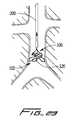
- FIG. 8is a perspective view of a third embodiment of the vein filter of the present invention formed of a single wire with a central (intermediate) crimping sleeve, and shown in the expanded configuration;
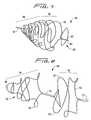
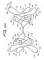
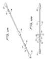
- FIG. 9is a perspective view of another alternate embodiment of the vein filter of the present invention having two filtering portions and two anchoring portions shown in the expanded configuration;
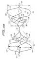
- FIG. 10Ais side view of the vein filter of FIG. 9 in the expanded configuration
- FIG. 10Bis a side view similar to FIG. 10A except at a slightly different angle;
- FIG. 10Cis a view similar to FIG. 10A except showing an alternate embodiment of the filter of the present invention in the expanded configuration having multiple anchoring members on each of the wires;
- FIG. 11is a front view of the vein filter of FIG. 9 in the expanded configuration
- FIG. 12Ais a perspective view of the vein filter of FIG. 9 in the collapsed configuration for delivery through a catheter or sheath into the vessel;
- FIG. 12Bis an enlarged side view of the distal and middle portions of the vein filter of FIG. 9 in the collapsed configuration of FIG. 12A ;
- FIG. 12Cis an enlarged perspective view of a portion of the vein filter of FIG. 12A showing the axial displacement of the anchoring members;
- FIG. 12Dis a view similar to FIG. 12A except showing the alternate embodiment of the vein filter of FIG. 10C having a series of anchoring members on each of the wires at the proximal and distal portions;
- FIG. 12Eis a side view of the middle and distal portions of the filter of FIG. 12D ;
- FIG. 13Ais a transverse cross-sectional view of the vein filter of FIG. 9 in the collapsed configuration of FIG. 12 showing the crimping sleeve encircling three wires within the delivery sheath;
- FIG. 13Bis a transverse cross-sectional view of the vein filter of FIG. 9 in the collapsed configuration of FIG. 12 showing an anchor member and adjacent wires within the delivery sheath;
- FIGS. 14-17illustrate the steps of insertion of the vein filter of FIG. 9 within the inferior vena cava of a patient in accordance with a first method, wherein:
- FIG. 14illustrates insertion of the delivery catheter through the femoral vein
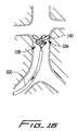
- FIG. 15illustrates the delivery sheath being advanced to the inferior vena cava just below (upstream) the juncture of the renal arteries;
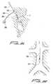
- FIG. 16illustrates the delivery sheath being withdrawn to enable one of the anchoring portions and one of the filtering portions to move to the expanded configuration
- FIG. 17illustrates the delivery sheath fully withdrawn to expose the other filtering portion and the other anchoring portion to enable movement to the expanded configuration
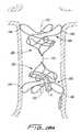
- FIG. 18Ais an enlarged view of the expanded filter of FIG. 17 showing a blood clot captured in the filter;
- FIG. 18Bis an enlarged view of an alternate embodiment of the filter in the expanded condition having longitudinally offset crimping sleeves
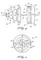
- FIG. 19is an enlarged view of one embodiment of the anchoring tube of the present invention having ground edges engaging the vessel wall;
- FIG. 20is an enlarged view of an alternate embodiment of an anchoring tube of the present invention having beveled edges engaging the vessel wall;
- FIGS. 21-23illustrate insertion of the vein filter of FIG. 9 within the inferior vena cava in accordance with a second method, wherein:
- FIG. 21illustrates insertion of the delivery catheter through the right jugular vein
- FIG. 22illustrates the delivery sheath being advanced downwardly past the juncture of the renal arteries to the inferior vena cava
- FIG. 23illustrates the delivery sheath being withdrawn to enable one of the anchoring portions and filtering portions to move to the expanded configuration
- FIG. 24illustrates insertion of the vein filter of FIG. 9 into the superior vena cava in accordance with a third method of the present invention
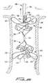
- FIG. 25is a side view, with the vessel shown in cross-section, illustrating a first embodiment of an instrument for grasping the filter wires for removing the vein filter of FIG. 9 through the internal jugular vein;
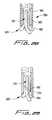
- FIG. 26Ais a side view of a distal end of a second embodiment of an instrument, having a series of barbs, for grasping the filter wires for removing the vein filter through the internal jugular vein;
- FIG. 26Bis a side view of the instrument of FIG. 26A illustrating the welded wire end of the vein filter of FIG. 26A retained within the instrument;
- FIG. 27Aa side view of a distal end of a third embodiment of an instrument, having a collapsible braided structure, for grasping the filter wires for removing the vein filter of FIG. 26A through the internal jugular vein;
- FIG. 27Bis a side view of the instrument of FIG. 27A illustrating the welded end of the vein filter retained within the instrument;
- FIG. 28a side view of a distal end of a fourth embodiment of an instrument, having a hook, for grasping the filter wires for removing the vein filter of FIG. 26A through the internal jugular vein;
- FIG. 29a side view of a distal end of a fifth embodiment of an instrument, having a spring biased finger, for grasping the filter wires for removing the vein filter of FIG. 26A through the internal jugular vein;
- FIG. 30is a side view, with the vessel shown in cross-section, illustrating a first embodiment of an instrument for grasping the crimping sleeve for removing the vein filter of FIG. 9 through the internal jugular vein;
- FIG. 31is a side view, with the vessel shown in cross-section, illustrating a second embodiment of an instrument for grasping the crimping sleeve for removing the vein filter of FIG. 9 through the internal jugular vein;
- FIG. 32is a side view illustrating the instrument of FIG. 31 used for removing the vein filter through the femoral vein;
- FIG. 33Ais a side view of a distal end of a third embodiment of an instrument, having a hook, for grasping the crimping sleeve for removing the vein filter through the internal jugular vein;
- FIG. 33Bis a transverse cross-sectional view of the instrument of FIG. 33A ;
- FIG. 34illustrates a distal end of an alternate embodiment of the vein filter terminating in an atraumatic spring tip
- FIG. 35illustrates a distal end of another alternate embodiment of the vein filter terminating in an atraumatic ball tip
- FIG. 36Ais a side view of a distal end of a first embodiment of an instrument, having a collet, for grasping the ball tip of the vein filter of FIG. 35 for removing the vein filter through the internal jugular vein;
- FIG. 36Bis a front view of the instrument of FIG. 36A ;
- FIG. 36Cis a side view showing the ball tip retained within the removal instrument of FIG. 36A ;
- FIG. 37illustrates a distal end of yet another alternate embodiment of the vein filter having a recess slightly proximal of the distal end.
- vein filters of the present inventionare described for placement within the inferior vena cava to capture blood clots or other particles which could otherwise pass to the lungs.
- These filtersare movable from a low profile collapsed configuration to facilitate insertion through the delivery sheath to an expanded position to enable the anchoring members to atraumatically contact the vessel walls to secure (mount) the filter within the inferior vena cava.
- the anchoring membersare configured to securely retain the filter in the vessel while allowing for disengagement from the vessel wall, if desired, to enable removal of the filter.
- the wire(s) which form the vein filters of the present inventionare looped to form an anchoring portion and a narrowed filtering portion, as will be described in detail below.
- this first embodiment of the vein filter of the present inventionis designated generally by reference numeral 10 .
- Vein filter 10is formed by a pair of wires, designated by reference numerals 12 and 14 .
- Wires 12 and 14are preferably circular in cross-section having a diameter preferably ranging from about 0.011 inches to about 0.020 inches, and preferably about 0.012 inches.
- the wires 12 and 14are held together, side by side, at their distal ends by a distal crimping sleeve 20 and held together, side by side, at their proximal ends by a proximal crimping sleeve 22 .
- a central or intermediate crimping sleeve 24is provided at an intermediate portion of wires 12 and 14 to retain middle portions of the wire together in a side-by-side relationship.
- the wirescan also be held by other means such as being welded or glued.
- An example of the wire ends being welded togetheris illustrated in FIGS. 26A and 27A .
- wires 12 and 14are wound in identical manners, except opposite to one another. That is, wire 12 , starting from proximal crimping sleeve 224 , weaves back and forth across an imaginary centerline “C” (or central longitudinal axis) to form a series of loops 12 b , 12 d , 12 g , 12 i and 12 k , on one side of the centerline. Bends or curves 12 a , 12 c , 12 e , 12 f , 12 h , 12 j and 12 l are on the other side of the centerline and form transitions for formation of the loops in wire 12 .
- Cimaginary centerline
- Each of the bends 12 a , 12 c , 12 e , 12 f , 12 h , 12 j and 12 lfaces in the downward direction enabling each of the loops 12 b , 12 d , 12 g , 12 i and 12 k to open in an upward direction as oriented in FIGS. 1 and 2 .
- Wire 14also weaves back and forth across the centerline forming loops 14 b , 14 d , 14 g , 14 i and 14 k on one side of the centerline and curves and bends 14 a , 14 c , 14 e , 14 f , 14 h , 14 j and 14 l on the other side of the centerline to from transitions for the loops.
- Each of the bends 14 a , 14 c , 14 e , 14 f , 14 h , 14 j and 14 lfaces in the upward direction and each of the loops 14 b , 14 d , 14 g , 14 i and 14 k opens in the downward direction as oriented in FIGS. 1 and 2 .
- wire 12forms upwardly directed loops (as viewed in the orientation of FIGS. 1 and 2 ) and wire 14 forms downwardly directed loops with the wire loops and bends 12 a - 12 l approximately 180 degrees out of phase with the corresponding wire loops and bends 14 a - 14 l.
- a central portion 12 m , 14 m of wires 12 and 14forms partial loops and extends substantially linearly through the central crimping sleeve 24 where they are contiguous and aligned side by side.
- the wires 12 and 14are preferably also contiguous as they extend linearly through the proximal, and distal crimping sleeves 22 , 20 , respectively.
- Partial loops 12 n and 14 nare formed in wires 12 and 14 before extending through distal crimping sleeve 20 and partial loops 12 p , 14 p extend from proximal crimping sleeve 22 .
- the wirespreferably do not touch as the loops are spaced apart and the loops of wire 12 do not cross over the loops of wire 14 .
- the center of the radii of the loops on one side as viewed in FIG. 1i.e. loops 14 i , 12 g , 14 d , and 12 b , are preferably substantially aligned such that an imaginary line drawn through such centers would be substantially parallel to the longitudinal axis of the filter 10 .
- the center of the radii of the loops 14 k , 12 i , 12 d and 14 b on the other side of the filter 10are also preferably substantially aligned such that an imaginary line drawn through such centers would be substantially parallel to the longitudinal axis of the filter 10 .
- the two imaginary lineslie in substantially the same transverse plane.
- the wires 12 , 14 of filter 10form an anchoring or mounting portion 30 and a filtering portion 28 .
- the anchoring portion 30is formed at a proximal portion to engage the vessel wall for securement of the filter 10 .
- the filtering portion 28is formed at a distal portion and has a diameter less than the diameter D 1 ( FIG. 3 ) of the anchoring portion 30 .
- the diameter of the filtering portionis sufficiently small to capture blood clots and prevent its passage through the filter 10 .
- proximal and distalare utilized for convenience for orientation purposes, since if the filter 10 is inserted into the inferior vena cava through the internal jugular vein instead of the femoral vein, the portion closer to the user, e.g. the “proximal portion”, will instead be the filtering portion 28 .
- the anchoring portion 30which includes the region between the intermediate and proximal crimping sleeves 24 , 22 , is substantially uniform in diameter (D 1 ) or height.
- the filter portion 20which includes the region between the intermediate sleeve 24 and the distal crimping sleeve 20 , progressively decreases in diameter towards the distal sleeve 20 from diameter D 2 to diameter D 3 . Consequently diameter D 2 of filter portion 32 is greater than diameter D 3 of filter portion 20 . This decrease in diameter helps to cause migration of the blood clots towards the center of the filter 10 to facilitate dissolution by the blood flow.
- the region between the drawn diameters D 2 and D 3functions as the filtering portion.
- the anchoring and filtering regionsare not rigidly defined and the diameters D 2 and D 3 and the portions 30 and 28 are identified for convenience.
- the diameter D 1 of the anchoring portion 30ranges from about 18 mm to about 30 mm.
- the diameter D 2 of the filtering portion 28preferably ranges from about 17 mm to about 29 mm; and the smaller diameter D 3 of the filtering portion 28 preferably decreases to as small as about 0.5 mm at the distal sleeve 20 .
- Other dimensionsare contemplated.
- the anchoring portion 30 defined hereindefines a region of the filter which is utilized to retain (mount) the filter 10 inside the vessel and the filtering portion 28 defines the region which captures particles such as blood clots. Consequently the region of the anchoring portion can alternatively terminate more distally of the intermediate crimping sleeve 24 or terminate more proximally of the crimping sleeve 24 . Similarly, a region of the filtering portion, i.e. the progressive decrease in diameter, can alternatively begin proximally of the intermediate crimping sleeve 22 or begin further distally than as illustrated in FIGS. 1 and 2 .
- anchoring and filtering portions 30 , 28need not be defined by the regions separated by intermediate crimping sleeve 24 .
- the anchoring portion 30 of the filter 10includes at least one vessel wall retention or securement (anchoring) member, designated by reference numeral 40 .
- the retention member 40is preferably in the form of a stainless steel tube and has a lumen 42 to receive respective wires 12 and 14 .
- the anchoring tube 40 (or 50 )is preferably attached to the wire 12 or 14 by crimping or welding.
- the anchoring tube 40has opposed beveled edges 44 , 46 which frictionally engage portions of the vessel wall in the manner described below.
- the anchor membercan be in the form of a cylindrically shaped tube 50 (see FIG. 5 ) with the edges 52 sharpened, e.g. by grinding, to engage the vessel. This is also described in more detail below.
- one tube 40 (or 50 )is positioned on wire 12 , at the largest diameter region of the anchoring portion 30 , tangent with loop 12 d ; and another tube 40 (or 50 ) is positioned on wire 14 , also at the largest diameter region of the anchoring portion 30 , tangent with loop 14 d .
- the anchoring members 40 (or 50 )are approximately 180 degrees apart. In this manner, when the filter 10 moves to its expanded configuration, the anchoring tubes will engage opposing sides of the vessel wall as described below. Although two anchoring members are shown, additional anchoring members can be provided. This is described below in conjunction with FIGS. 12D and 12E , it being understood that the train of staggered anchoring members could be provided in this embodiment of the filter as well.
- FIGS. 5A-5C and 6 A- 6 BThe collapsed configuration of the filter 10 for delivery inside the vessel will now be described with reference to FIGS. 5A-5C and 6 A- 6 B. Note that although the collapsed configuration is illustrated with cylindrical tubes 50 , it is understood that anchoring tubes 40 would be positioned in a similar manner.
- the first and second wires 12 , 14When collapsed, the first and second wires 12 , 14 are in a straightened configuration substantially parallel with one another and substantially aligned with their respective longitudinal axis.
- the cylindrical anchoring members 50are axially displaced to conserve space within the delivery catheter. Consequently, as shown in the transverse sections of FIGS. 6A and 6B , the largest cross sectional area occupied by the filter 10 is defined by the outer diameter D 4 of one of the wires (e.g. wire 14 ) plus the outer diameter D 5 of the anchoring tube 50 . Since the other anchoring tube(s) are staggered, i.e.
- the overall collapsed diameteris minimized which would not be the case if the anchoring tubes 50 were axially aligned in the collapsed configuration since the diameter would be then be defined by the sum of the diameters D 5 of adjacent anchoring tubes. (2 ⁇ D 5 ).
- This axial displacement of the anchoring tubethereby enables the size (diameter) of the delivery sheath 210 to be minimized.
- a slight gap, not shown,could be provided between the outer wall of the anchoring tube 50 and delivery sheath 210 to provide clearance to facilitate exit from the sheath 210 .
- FIG. 6Bshows the diameter of the two wires within the crimping sleeve 22 , with the total cross sectional region occupied by the collapsed filter defined by the outer diameter D 6 of the sleeve 22 .
- a slight gap between the outer diameter of the crimping sleeve 22 and delivery sheath 210is designated by reference letter “g”.
- the inner diameter of the crimping sleeveis equal to the sum of the outer diameters of the wires 12 , 14 , with the thickness “t” of the sleeve defined by the distance between the inner wall and outer wall and being sufficient to rigidly retain the wires.
- the anchoring tubeis preferably maintained equal to or less than the numerical difference between the outer diameter of the sleeve and the outer diameter of the wire. This keeps the overall cross-sectional region (or height) of the filter in the collapsed position at a minimum as other portions of the filter 10 in the collapsed position will not exceed the outer diameter of the crimping sleeve.
- the outer diameter D 4 of the wires 12 and 14is preferably about 0.012 inches.
- the inner diameter D 6 of each crimping sleevepreferably ranges from about 0.022 inches to about 0.040 inches, and preferably is about 0.024 inches. That is, the inner diameter of the crimping sleeve is preferably twice the diameter of the wire.
- the outer diameter of each crimping sleevepreferably ranges from about 0.050 inches (18 gauge) to about 0.065 inches (16 gauge), and is preferably about 0.058 inches (17 gauge).
- the outer diameter D 5 of the anchoring tubepreferably ranges from about 0.030 inches to about 0.054 inches, and is preferably about 0.046 inches. With these dimensions, a 6 French delivery sheath 27 (2 mm in outer diameter) to deliver the filter 10 can be utilized.
- wires 12 and 14are preferably made of shape memory metal material, such as Nitinol, a nickel titanium alloy.
- shape memory metal materialsuch as Nitinol, a nickel titanium alloy.
- the memorized configuration of the filter 10is shown in FIG. 1 .
- cold salineis injected into the delivery sheath 210 and around the wires 12 and 14 in their collapsed position within the delivery sheath 210 .
- This shape memory materialcharacteristically exhibits rigidity in the austenitic state and more flexibility in the martensitic state.
- the cold salinemaintains the temperature dependent wires 12 , 14 in a relatively softer condition as they are in the martensitic state within the sheath. This facilitates the exit of wires 12 and 14 from the sheath 210 as frictional contact between the wires 12 , 14 and the inner surface of the sheath would otherwise occur if the wires were maintained in a rigid, i.e. austenitic, condition.
- the wiresare no longer cooled and are exposed to the warmer body temperature, which causes the wires to return their austenitic memorized configuration of FIG. 1 .
- the filter 10can be inserted through the jugular vein in the neck of the patient or through the femoral vein in the leg of the patient. It can also be inserted through the superior vena cava. If inserted through the femoral vein, the filter would be positioned within sheath 21 so that the anchoring portion 30 is closer to the user and the filtering portion 28 is further from the user. If inserted through the jugular or superior vena cava, the filter would be positioned within sheath 21 so that the anchoring portion 30 is further from the user and the filtering portion 28 is closer to the user. Insertion of the filter will be better understood from the detailed description below of the filter insertion methods.
- the filtercan be readily removed from the inferior vena cava.
- Instrumentssuch as those described below in connection with FIGS. 25-33 can be inserted through the internal jugular vein (or the superior vena cava) and advanced into the inferior vena cava to grasp the filter in the manner described below for filter 100 . That is, a removal tool can be utilized to grasp one or both of the wires of the filter, or alternatively, used to grasp the proximal crimping sleeve 22 to collapse the filter and disengage the anchoring members from the vessel wall. The filter could then be removed through the femoral vein.
- FIG. 8illustrates an alternate embodiment of the filter of the present invention, designated generally by reference numeral 60 .
- Filter 60is similar to filter 10 , except instead of being formed of two wires, filter 60 is formed of a single wire 61 .
- Filter 60is crimped at the proximal end by sleeve 72 and at a middle or intermediate portion by crimping sleeve 74 .
- the distal end 66 of filter wire 60loops around at loop 68 , and is therefore not crimped with a sleeve as in the embodiment of FIG. 1 .
- Filter 60also preferably has anchoring tubes (not shown) on anchoring portion 62 similar to anchoring tubes 40 of FIG. 1 or tube 50 of FIG. 5 on loops 67 and 69 . In all other respects, e.g. narrowed filtering portion 64 , loops about 180 degrees out of phase, etc., filter 60 is identical to filter 10 .
- FIG. 7illustrates another alternate embodiment of the filter of the present invention formed by a single wire.
- Wire 82 of filter 80wraps in a similar fashion as wire 61 of filter 60 . That is, wire 82 forms alternating loops, i.e. downwardly directed and upwardly directed, as oriented in FIG. 7 , as it extends from a proximal end 85 in anchoring portion 86 to distal loop 87 at a filtering portion 88 . Wire 82 then extends proximally from the distal loop 87 in an alternating loop pattern forming upwardly and downwardly directed loops.
- Filter 80preferably includes a proximal crimping sleeve (removed to illustrate the wire) to retain the free ends 87 , 89 of wire 82 .
- Filter 80also preferably includes an anchoring tube (not shown) on respective loops of the anchoring portion 86 , similar to anchor 40 of FIG. 1 or anchor 50 of FIG. 5 .
- the wire loops at the distal end and the wire endsare crimped, welded or secured by other means at the proximal end. It is also contemplated that alternatively the wire can loop at its proximal end and the two ends secured at the distal end. Also, instead of a crimping sleeve, the wire ends can be glued, welded (see e.g. FIGS. 26A and 27A ) or attached by other means.
- Filters 60 and 70can be removed through the femoral vein in a similar manner as filter 10 .
- FIGS. 9-13An alternate embodiment of the filter of the present invention, having two anchoring portions and two filtering portions is illustrated in FIGS. 9-13 and designated generally by reference numeral 100 .
- the filter 100having two symmetric anchoring and filtering portions, can be inserted into the inferior vena cava in either direction, e.g. downwardly from the right jugular vein access or upwardly from the femoral vein access, without concern of its proximal/distal orientation.
- the filter 100having two symmetric portions, can also be removed in either direction, regardless of the direction which it is inserted.
- filter 100is formed by three wires 112 , 114 and 116 .
- the three wires 112 , 114 and 116form first and second anchoring portions 102 , 104 and first and second filtering portions 106 , 108 .
- the first filtering and anchoring portions 102 , 106extend between proximal crimping sleeve 120 and intermediate (central) crimping sleeve 124 ; the second filtering portion 108 and anchoring portion 104 extend between intermediate crimping sleeve 124 and distal crimping sleeve 122 .
- Anchoring portion 102is substantially identical to anchoring portion 104 , except it extends in the opposite direction.
- the filtering portion 106is substantially identical to filtering portion 108 except it also extends in the opposite direction.
- the filtercan be placed inside a delivery catheter and inserted either through the jugular vein or the femoral vein using the same delivery catheter and in either proximal/distal orientation.
- the wiresare described as being held in side by side relationship by a crimping sleeve, alternatively the wires can be welded (see e.g. FIGS. 26A , 27 A), glued, or held together by other means.
- the provision of two anchoring portions 104 , 102 on opposing endshelps to center the filter 100 within the vessel which in turn helps to maintain the captured blood clots in the center of the filter 100 . If the blood clots are maintained in the center, they will more easily be dissolved or washed away by the blood flow.
- wire 110forms three loops 110 a , 110 b , and 110 c between the proximal and intermediate crimping sleeves 120 , 124 with loops 110 a and 110 c extending in a first direction and a loop 110 b extending in an opposite second direction.
- Wire 110further forms two loops 110 d and 110 f , extending in the second direction and one loop 110 e extending in the first direction in the region between the intermediate crimping sleeve 124 and the distal crimping sleeve 122 .
- Wire 112 in the first anchoring/filtering portion defined between the proximal and intermediate crimping sleeves 120 , 124forms two loops 112 a , 112 c extending in a third direction and a third loop 112 b extending in a fourth direction opposite the third direction.
- loops 112 d and 112 f of wire 112extend in the fourth direction and loop 112 e extends in the third direction.
- Wire 114 in the first anchoring/filtering portion defined between the proximal and intermediate crimping sleevesforms two loops 114 a , 114 c extending in a fifth direction and a third loop 114 b extending in a sixth opposite direction. Loops 114 d and 114 f extend in the sixth direction and loop 114 e extends in the fifth direction. These loops 114 d , 114 e and 114 f are formed in the second anchoring/filtering portion between the distal and intermediate crimping sleeves 122 , 120 .
- the corresponding loops of wires 110 , 112 , 114are preferably about 120° out of phase. It should be appreciated that arrangements other than 120 degree spacing are contemplated. Additionally, “opposite” directions of the loops is not limited to 180 degrees, but encompasses different directions.
- the loops of the wireshave axially spaced apexes in both the mounting and filter portions.
- An anchoring member 140is positioned on each of the wires 110 , 112 , 114 in the first anchoring portion 102 and the second anchoring portion 104 . More specifically, the anchoring members 140 are positioned on the region of the wires 110 , 112 and 114 having the largest diameter (height) H or greatest distance from the longitudinal axis, namely on loops 110 a , 112 a , 114 a and loops 110 f , 112 f and 114 f as shown. The distances H are preferably substantially equal but alternatively can vary. Note the anchoring members are removed from FIGS. 9 , 10 B and 11 for clarity.
- the anchoring (securement) memberhas a lumen 142 to receive the respective wire therethrough.
- the anchoring member 140is preferably a cylindrical shaped metallic tube with opposed sharpened edges 144 formed by grinding the ends. It should be understood, that the anchoring tube 40 of FIG. 1 with sharpened bevelled edges could alternatively be utilized.
- the ground edges 144are designed to frictionally engage the vessel wall in the manner described in more detail below to retain the filter 100 inside the vessel.
- filter 100 ′has a pair of anchoring members 140 ′ on each of the wires 110 ′, 112 ′ 114 ′ in the first anchoring portion 102 ′ and in the second anchoring portion 104 ′.
- the filter 100 ′is identical to filter 100 with corresponding parts labeled with a prime (′). It is also contemplated that additional anchoring members can be placed on the wires 110 ′, 112 ′ and 114 ′.
- the diameter or height of the anchoring portions 102 , 104is greater than the diameter of the filtering portions 106 , 108 . That is, the diameter of the filter 100 increases from the intermediate region (or from intermediate crimping sleeve 124 ) towards the proximal end and towards the distal end, thereby forming two reduced diameter filter portions closer to the intermediate region of the filter 100 . Viewed another way, two symmetrical portions are provided, each having a filtering portion decreasing in diameter toward the intermediate portion. Since the filtering portions progressively decrease towards the center, the captured blood clots will be directed toward the center of the filter 100 and the center of the blood vessel, thereby enabling it to be more easily dissolved or washed away by the blood flow.
- Diameters E 1 and E 2 in FIG. 10Bare taken in one transverse line of the anchoring portion 102 and filtering portion 106 , respectively, for an example of how these diameters change. It should be appreciated, that within each portion, the diameters could vary. In a preferred embodiment the diameter of the first and second anchoring portions 102 , 104 ranges from about 18 mm to about 30 mm, and the diameter of the first and second filtering portions preferably progressively decreases to about 0.5 mm. Other dimensions are also contemplated.
- the compactness of the filter 100 of the present inventioncan be appreciated by reference to FIGS. 12-13 .
- the wires 110 , 112 , and 114are substantially straight and substantially parallel, i.e. substantially aligned with a longitudinal axis.
- Adjacent anchoring tubes 140are axially displaced to minimize the overall diameter of the filter 100 . Consequently, the largest diameter of the filter 100 in the collapsed configuration for delivery will be defined by the outer diameter F 1 of one of the crimping sleeves, e.g. crimping sleeve 124 of FIG. 12A .
- each wirehaving, by way of example, a diameter of about 0.011 inches to about 0.020 inches, and preferably about 0.012 inches.
- the crimping sleevewhich circumscribes the three circular cross-sectional wires, is defined by a diameter factor of 2.155, meaning that the inner diameter of the sleeve can be as small as the 2.155 times the wire diameter. Therefore, if the wire diameter is about 0.012 inches, the inner diameter of the crimping sleeve can be about 0.0256 inches (2.155 ⁇ 0.012). If the wall thickness of the sleeve is about 0.010 inches, the outer diameter would be about 0.0456 inches.
- the outer diameter of the anchoring tubeis preferably selected so that in the collapsed configuration of the filter, the anchoring tube and adjacent wires do not occupy a transverse dimension exceeding the outer diameter of the crimping sleeve, such as shown in FIG. 13B , to maintain the low profile of the filter in the collapsed configuration.
- the diameter of the anchoring tubeis the reference dimension, than the crimping sleeve outer diameter preferably does not exceed the diameter of the anchoring tube and the adjacent wires to maintain the low profile.
- FIGS. 12D and 12Eillustrate the collapsed configuration of filter 100 ′ of FIG. 10C with a pair of anchoring members 140 ′ on each of the three wires at the distal portion adjacent distal crimping sleeve 122 ′ and at the proximal portion adjacent proximal crimping sleeve 120 ′.
- filter 100is preferably made of shape memory metal material, such as Nitinol.
- Cold salineis injected into the delivery catheter and around the wires 110 , 112 , 114 in their collapsed position within the delivery catheter to facilitate passage of the wires 110 , 112 , and 114 through the lumen of the delivery catheter and into the vessel.
- This shape memory materialcharacteristically exhibits rigidity in the austenitic state and more flexibility in the martensitic state.
- the cold salinemaintains the temperature dependent wires 110 , 112 and 114 in a relatively softer condition as they are in the martensitic state within the catheter.
- the filter 100can be inserted through the femoral vein or the right jugular vein and into position in the inferior vena cava, just below the renal arteries. Since the filter 100 is symmetrical, e.g. two filtering portions, it can be loaded into the delivery sheath or catheter in either orientation and inserted in either direction into the inferior vena cava.
- FIGS. 14-18One method of insertion of the filter 100 of the present invention is illustrated in FIGS. 14-18 .
- a delivery catheter 200 having a hub 202is inserted through a leg incision and into the femoral vein “f” of the patient.
- the delivery catheter 200is advanced through the iliac arteries into the inferior vena cava just below (upstream with respect to blood flow)) of the renal arteries.
- Note that the delivery catheteris introduced through an introducer sheath which is not shown for clarity.
- the introducer sheathis inserted over a guidewire (also not shown) and advanced to the target site.
- the guidewireis then removed and the delivery catheter is inserted through the lumen in the sheath to the target vessel.
- Extending from hub 202 of delivery catheter 200is tubing 204 and valve assembly 206 to enable saline to be injected into delivery catheter 200 to maintain the softened martensitic state of the vein filter within the catheter 200 so the vein filter is in the substantially straightened configuration as in FIG. 12 .
- a one-way stopcockcan be provided to control saline infusion.
- a metal retaining rod 205is positioned within the delivery catheter 200 and inserted with the catheter 200 .
- the delivery catheter 200is withdrawn proximally, with rod 205 held in a fixed position to ensure the filter 100 is not pulled back with the catheter 200 .
- Withdrawal of the catheter 200exposes one of the anchoring portions, e.g. second anchoring portion 104 and one of the filtering portions, e.g. second filtering portion 108 , enabling return to the austenitic expanded configuration as the filter is warmed by body temperature (see FIG. 16 ).
- Further withdrawal of the delivery catheter 200releases the other filtering and anchoring portions, e.g. first filter portion 102 and first anchoring portion 106 , as shown in FIG.
- FIG. 18Aillustrates a blood clot “P” captured in the filtering portion 106 of the filter 100 . Note that if the filter 100 was loaded in catheter 200 in the opposite direction, the filtering portion 104 would be upstream of filtering portion 102 , when placed within the vessel, and the filtering portion 104 would function to capture blood clots.
- FIG. 18Billustrates an alternate embodiment of the vessel filter.
- the vessel filteris identical to filter 100 of FIG. 18A except that the crimping (connecting) sleeves 422 and 420 are longitudinally offset with respect to central crimping sleeve 424 and with respect to each other. This off centering of the sleeves could reduce turbulence by positioning the obstructions out of alignment.
- one or more of the wires 410 , 412 and 414could be of a different length so the sleeves are off-center.
- filter 400has filtering portions 406 , 408 and anchoring portions 402 , 404 , although the filter design is asymmetric.
- FIGS. 19 and 20illustrate the engagement of the anchoring tube with the vessel.
- the surface 145 of tube 140presses inwardly into the vessel wall, creating an indented region so that ground edges 142 of anchoring tube 140 can press against opposing vessel wall portions “v 1 ” and “v 2 ”. This frictional contact retains the filter 100 .
- FIG. 20the engagement of the anchoring tube 40 of FIG. 1 is illustrated.
- Bevelled edges 44 , 46engage opposing sides “v 1 ” and “v 2 ” of the vessel, formed by the indentation as surface 45 presses against the vessel wall.
- a series of anchoring tubes 140 on the distal portion and proximal portion of each wireengage the vessel wall.
- FIGS. 21-23illustrate an alternate insertion method through the right internal jugular vein “j”.
- Delivery catheter 200having a hub 202 , a tube 204 and valve assembly 206 for injection of saline is inserted through the right jugular vein, and advanced past the heart and into the inferior vena cava just past the juncture of the renal arteries.
- the filter 100is contained within the delivery catheter 200 in the collapsed configuration.
- the delivery catheter 200is advanced adjacent the surgical site so that distal tip 20 extends past the juncture of the renal arteries as shown in FIG. 22 .
- the delivery catheter 200is then retracted, with rod 205 preventing proximal movement of the filter 100 , exposing the second filtering portion and second anchoring portion 102 ( FIG.
- the filter 100can be inserted into the inferior vena cava in either orientation since once expanded, the upstream filtering portion will capture blood clots and the two anchoring portions will help retain the filter 100 anchored and centered in the vessel.
- FIG. 24illustrates another alternate method of insertion wherein the delivery catheter 200 is inserted directly into the superior vena cava “s” and advanced into the inferior vena cava in the same manner as described in FIGS. 22 and 23 .
- filters 10 , 60 , and 80can be inserted through the femoral vein, jugular vein, superior vena cava, etc. in a similar manner as described above for filter 100 .
- the filteris released by withdrawal of the delivery catheter as described.
- the filtercan be released by pushing or advancing the filter from the delivery catheter. Additionally, release can be achieved by a combination of withdrawal of the catheter and advancement of the filter.
- proximal and distal for filter 100are utilized for convenience for orientation purposes, since the filter 100 can be inserted in either orientation.
- the filter 100 (and 100 ′)can, if desired, be withdrawn intravascularly.
- the filterdoes not require any additional components for removal from the vessel.
- the filtercan simply be grasped by one or more of the wires.
- the filtercan alternatively be grasped for removal at either the proximal crimping sleeve 120 or the distal crimping sleeve 122 which, as described above, retains the three wires. Due to the configuration of the filter, and particularly the symmetrical anchoring and filtering portions, the filter 100 (and 100 ′) can be removed from either end regardless of the direction in which it is inserted.
- a filter removal toolcan be inserted through either the internal jugular vein (or superior vena cava) or through the femoral vein to access the filter positioned in the inferior vena cava.
- the filter removal instrumentengages the filter wires or crimping sleeve, and applies an axial force to the filter to collapse the filter, disengage the anchoring members, and withdraw it through the vein in which the removal instrument was initially inserted.
- FIGS. 25 and 30 - 33illustrate several different instruments for removing vessel filter 100 .
- FIGS. 26-29illustrate different instruments for removing vessel filters having welded wire ends.
- a removal tool 300(only the distal portion is shown) has a flexible shaft 301 and three elongated wire engaging members 302 , 304 , and 306 extending therefrom.
- the wire engaging members 302 , 304 , and 306each have a lateral slot 312 , 314 , 316 , respectively, to engage one of the wires 110 , 112 , and 114 .
- the tool 300is inserted through the internal jugular vein with the wire engaging members 302 , 304 , 306 retracted within shaft 301 .
- the members 302 , 304 and 306are advanced from the shaft 301 and manipulated so that the lateral slots 312 , 314 and 316 engage the respective wire of the second anchoring portion 104 .
- the engaging members 302 , 304 , and 306are manipulated individually.
- the tool 300is pulled in the opposite direction of insertion, i.e. a longitudinal force is applied in the direction of the arrow, thereby applying an axial pulling force on the filter 100 .
- the filtercollapses as the wires are pulled toward a straightened position and the anchoring members 140 disengage from the vessel wall without causing trauma to the wall.
- the filter wires 110 , 112 and 114are pulled inside hollow shaft 301 to a more straightened position and the filter is removed from the vessel wall.
- tool 300is shown from an internal jugular (or superior vena cava) approach, alternatively the tool 300 can be inserted through the femoral vein. In this approach, the tool operates in the identical fashion except that it would engage wires 110 , 112 , 114 in the first anchoring portion 102 and withdraw the filter 100 through the femoral vein.
- the wire engaging members 302 , 304 , and 306are described as slidable within the shaft 301 to pull the filter 100 within the shaft 301 . It is also contemplated that the wire engaging members 302 , 304 and 306 can be fixedly attached to shaft 301 , and the shaft 301 positioned within a catheter (not shown). In this version, the shaft and wire engaging members would be inserted into the vessel with the engaging members withdrawn inside the catheter, and subsequently advanced relative to the catheter so that the engaging members protrude therefrom to engage the wires. The filter 100 would then be pulled along with the engaging members and shaft within the catheter for removal from the vessel.
- a graspercan be utilized.
- the removal toolhas three graspers which would be inserted through shaft 301 .
- the grasperswould have either one of the jaws or both jaws movable between an open position and a closed clamping position to grasp the respective wire. That is, each pair of jaws, in the open position, would be placed around one of the respective wires 110 , 112 , 114 , and the jaws would be manipulated, preferably individually, from the proximal end of the tool to close the jaws around the respective wire.
- the jawscan be configured in a similar configuration as that described below with respect to FIG. 30 .
- the toolOnce firmly grasped, the tool would be pulled in the opposite direction of insertion to disengage and withdraw the filter.
- the tool(graspers) can be inserted in either direction, i.e. femoral access or internal jugular/vena cava access.
- the grasperscan be withdrawn within shaft 301 , or alternatively, as explained with respect to the aforedescribed embodiment, the graspers and shaft can be placed inside a catheter and moved relative to the catheter. The filter would thus be withdrawn with the graspers and shaft into the catheter for removal from the vessel.
- FIGS. 26A and 26Billustrate an alternate embodiment of a removal tool, designated by reference numeral 340 , used to remove the filter having wire ends welded together instead of a crimping sleeve as described above.
- the filter 100 ′′(only the distal end is shown) terminates in wires 110 ′′, 112 ′′, and 114 ′′ welded together to form welded end 101 ′′.
- Filter removal tool 340(only the distal end is shown) has a series of flexible barbs 342 extending from the interior surface 344 of wall 345 into lumen 346 . Removal tool 340 is inserted over welded end 101 ′′ to engage the wires.
- the barbs 342are oriented to allow advancement of the wires within lumen 346 in the direction of the arrow, but prevent movement of the wires in the opposite direction.
- the wiresare firmly locked within the tool 340 and the tool can be pulled in the direction opposite its insertion direction to pull and collapse the filter to remove it from the vessel.
- FIGS. 27A and 27Billustrate an alternate embodiment of a removal tool for removing filter 100 ′′.
- Removal tool 360(only the distal end is shown) has a tubular braided structure 362 within tube 364 which is movable between an expanded and a collapsed position.
- the braided structure 362is placed over the welded end 101 ′′ in the expanded position, and then pulled in the direction of the arrow of FIG. 27A to collapse the braided structure 362 radially inwardly around welded end 101 ′′ (see direction of arrows of FIG. 27A ) to frictionally engage the wires 110 ′′, 112 ′′, 114 ′′ to remove the filter 100 ′′.
- the filter 100 ′′is then removed with the tubular braid 362 through lumen 365 of tool 360 .
- the removal tool 380has a hook 382 which is slidable to engage the wires of the filter 100 ′′ just below the welded region 101 ′′. Retraction of the hook 382 pulls the filter 100 ′′ into inner tube 383 . Inner tube 383 is positioned within tube 385 .
- a spring biased finger 392is attached to the wall 391 of removal tool 390 by a pin 394 .
- the welded end 101 ′′ of vein filter 100 ′′is retained in the tool 390 by the engagement of finger 392 just below the welded region 101 ′′.
- FIGS. 30-33illustrate an alternate approach to removing the vessel filter wherein the wire retaining sleeve, e.g. the crimping sleeve, is engaged by the filter removal tool.
- a grasper 400(only the distal portion is shown) having a flexible hollow shaft 401 and a pair of jaws 404 , 406 are inserted to the inferior vena cava from an internal jugular or superior vena approach. Jaws 404 , 406 extend from shaft 401 and are movable from an open position to a closed position to grasp distal retaining sleeve 122 .
- one jawcan be fixed and the other jaw moved relative to the fixed jaw between an open and closed position.
- the jaws 404 , 406are pulled in the direction of the arrow (opposite the direction of insertion) to apply an axial force on the filter 100 to collapse the filter and disengage the anchoring members 140 from the vessel wall.
- the filter 100moves toward a collapsed straightened position and is pulled by the jaws 404 , 406 inside the flexible shaft 401 as the jaws are retracted within the shaft 401 to remove the filter therethrough.
- the grasper 400can be placed within a catheter for slidable movement therein and the filter 100 withdrawn through the catheter as the jaws and shaft are retracted therein.
- FIG. 30illustrates the tool 400 grasping distal crimping sleeve 122 . It is also contemplated that the tool 400 can alternatively be inserted through the femoral vein to grasp proximal crimping sleeve 120 for removal of the filter 100 through the femoral vein.
- FIG. 31illustrates another embodiment of a filter removal tool (only a distal portion is shown), designated generally by reference numeral 500 , in the form of a snare having a wire 502 extending from flexible shaft 501 .
- the snare wire 502is inserted from an internal jugular (or superior vena cava) approach to access the filter 100 implanted within the inferior vena cava.
- the wire 502is placed adjacent the edge of the distal crimping sleeve 122 , and tightened to close the loop against the crimping sleeve edge by applying tension at a proximal end to firmly engage the filter 100 .
- the filter 100is then collapsed and the anchoring members 140 disengaged as the snare pulls the filter either through shaft 501 as wire 502 is retracted within shaft 501 or through a catheter (not shown) along with the shaft 501 for removal of the filter 100 in the direction of the arrow.
- FIG. 32illustrates a femoral approach to the filter 100 .
- wire 502 of snare 500is placed adjacent the edge of the proximal crimping sleeve 120 and tensioned to grasp the filter 100 .
- the filter 100would then be removed in the direction of the arrow, i.e. through the femoral vein.
- FIGS. 33A and 33Bshow an alternate instrument for removing vein filter 100 by engagement of the crimping sleeve.
- Removal instrument 600has an outer tube 608 , an inner tube 607 , and a hook 602 extending through lumen 604 in wall 606 of tube 607 .
- Hook 602is advanced through lumen 604 to engage the edge of distal crimping sleeve 122 .
- the hookis preferably slidable within lumen 604 to pull sleeve within lumen 605 , and the instrument 600 and filter are retracted within a sheath.
- FIGS. 34 and 35illustrate alternate embodiments of the vein filter having an atraumatic tip.
- filter wires 810 , 812 , and 814 of filter 800terminate in a spring tip 815 similar to atraumatic spring tips found in guidewires.
- the filter 850terminates in a ball tip 852 .
- Such atraumatic tipped filterscan be removed in similar fashions as those described above, e.g. grasping the individual wires or the tip by graspers, a snare, hook, etc.
- the vein filter of FIG. 35could further be removed by a collet 702 as shown in FIGS. 36A and 36B .
- Collet 702 of removal instrument 700is opened as it is advanced past wall 704 to create an opening 706 for ball tip 852 . Once the ball tip 852 is grasped, collet 702 is pulled back into housing 705 in the direction of the arrow in FIG. 36C , with walls 704 camming the collet to the closed position of FIG. 36C .
- FIG. 37illustrates yet another embodiment of the vein filter, designated by reference numeral 900 , having a circumferential recess or indentation 905 formed in the welded region 915 of the wires 910 , 912 and 914 .
- a snare or other grasping toolcan be placed in the recess and utilized to grasp and remove the filter.
- An indentation 905can also be formed in a welded region at the opposite end of the filter 900 .
- the foregoing removal toolscan also be utilized to reposition the vein filter rather than remove (retrieve) it.
- the toolswould be inserted and would function to grasp the filter in a similar manner as described above, but rather than remove the filter, it would move it within the vessel and then release it. The tool would then be removed, leaving the vein filter in place.
Landscapes
- Health & Medical Sciences (AREA)
- Cardiology (AREA)
- Oral & Maxillofacial Surgery (AREA)
- Transplantation (AREA)
- Engineering & Computer Science (AREA)
- Biomedical Technology (AREA)
- Heart & Thoracic Surgery (AREA)
- Vascular Medicine (AREA)
- Life Sciences & Earth Sciences (AREA)
- Animal Behavior & Ethology (AREA)
- General Health & Medical Sciences (AREA)
- Public Health (AREA)
- Veterinary Medicine (AREA)
- Surgical Instruments (AREA)
- Food-Manufacturing Devices (AREA)
- Filtration Of Liquid (AREA)
- Pressure Vessels And Lids Thereof (AREA)
Abstract
Description
- inserting through a vessel in either a first direction or a second direction a catheter having a filter positioned therein in a collapsed configuration so that wire sections of the filter are in a substantially elongated configuration;
- releasing the filter from the catheter to enable the filter to move to an expanded configuration, in the expanded configuration a pair of mounting portions expand to a first diameter and a pair of filter portions expand to a second smaller diameter;
- leaving the filter in the vessel for a period of time;
- inserting after the period of time in either the first direction or the second direction a filter removal tool to engage at least one of the wire sections; and
- moving the tool in a direction opposite the insertion direction of the tool to move the filter towards the collapsed configuration.
- inserting through a vessel a catheter having a filter positioned therein in a collapsed configuration so that wire sections of the filter are in a substantially elongated configuration, the wire sections held at a proximal portion by a proximal retaining sleeve and held at a distal portion by a distal retaining sleeve;
- releasing the filter from the catheter to enable the filter to move to an expanded configuration, in the expanded configuration a pair of mounting portions expand to a first diameter and a pair of filter portions expand to a second smaller diameter;
- leaving the filter in the vessel for a period of time;
- inserting a filter removal tool in a first direction after a period of time to engage one of the retaining sleeves; and
- moving the tool in a direction opposite the first insertion direction of the tool to move the filter towards the collapsed configuration.
Claims (15)
Priority Applications (1)
| Application Number | Priority Date | Filing Date | Title |
|---|---|---|---|
| US10/899,471US8821528B2 (en) | 2001-06-18 | 2004-07-26 | Removable vein filter |
Applications Claiming Priority (4)
| Application Number | Priority Date | Filing Date | Title |
|---|---|---|---|
| US09/883,819US6623506B2 (en) | 2001-06-18 | 2001-06-18 | Vein filter |
| US09/883,818US6793665B2 (en) | 2001-06-18 | 2001-06-18 | Multiple access vein filter |
| US09/911,097US6783538B2 (en) | 2001-06-18 | 2001-07-23 | Removable vein filter |
| US10/899,471US8821528B2 (en) | 2001-06-18 | 2004-07-26 | Removable vein filter |
Related Parent Applications (1)
| Application Number | Title | Priority Date | Filing Date |
|---|---|---|---|
| US09/911,097DivisionUS6783538B2 (en) | 2001-06-18 | 2001-07-23 | Removable vein filter |
Publications (2)
| Publication Number | Publication Date |
|---|---|
| US20050055046A1 US20050055046A1 (en) | 2005-03-10 |
| US8821528B2true US8821528B2 (en) | 2014-09-02 |
Family
ID=27420513
Family Applications (1)
| Application Number | Title | Priority Date | Filing Date |
|---|---|---|---|
| US10/899,471Expired - Fee RelatedUS8821528B2 (en) | 2001-06-18 | 2004-07-26 | Removable vein filter |
Country Status (6)
| Country | Link |
|---|---|
| US (1) | US8821528B2 (en) |
| EP (1) | EP1399083A2 (en) |
| JP (1) | JP2005519644A (en) |
| AU (1) | AU2002312441B8 (en) |
| CA (1) | CA2455349C (en) |
| WO (1) | WO2002102280A2 (en) |
Cited By (10)
| Publication number | Priority date | Publication date | Assignee | Title |
|---|---|---|---|---|
| US20120071918A1 (en)* | 2008-03-07 | 2012-03-22 | Zahid Amin | Heart Occlusion Devices |
| US9119607B2 (en) | 2008-03-07 | 2015-09-01 | Gore Enterprise Holdings, Inc. | Heart occlusion devices |
| US9474517B2 (en) | 2008-03-07 | 2016-10-25 | W. L. Gore & Associates, Inc. | Heart occlusion devices |
| US9770232B2 (en) | 2011-08-12 | 2017-09-26 | W. L. Gore & Associates, Inc. | Heart occlusion devices |
| US9808230B2 (en) | 2014-06-06 | 2017-11-07 | W. L. Gore & Associates, Inc. | Sealing device and delivery system |
| US9949728B2 (en) | 2007-04-05 | 2018-04-24 | W.L. Gore & Associates, Inc. | Septal closure device with centering mechanism |
| US10792025B2 (en) | 2009-06-22 | 2020-10-06 | W. L. Gore & Associates, Inc. | Sealing device and delivery system |
| US10806437B2 (en) | 2009-06-22 | 2020-10-20 | W. L. Gore & Associates, Inc. | Sealing device and delivery system |
| US10828019B2 (en) | 2013-01-18 | 2020-11-10 | W.L. Gore & Associates, Inc. | Sealing device and delivery system |
| US11375988B2 (en) | 2003-07-14 | 2022-07-05 | W. L. Gore & Associates, Inc. | Patent foramen ovale (PFO) closure device with linearly elongating petals |
Families Citing this family (29)
| Publication number | Priority date | Publication date | Assignee | Title |
|---|---|---|---|---|
| US7314477B1 (en) | 1998-09-25 | 2008-01-01 | C.R. Bard Inc. | Removable embolus blood clot filter and filter delivery unit |
| US6793665B2 (en)* | 2001-06-18 | 2004-09-21 | Rex Medical, L.P. | Multiple access vein filter |
| US9204956B2 (en) | 2002-02-20 | 2015-12-08 | C. R. Bard, Inc. | IVC filter with translating hooks |
| US7704267B2 (en) | 2004-08-04 | 2010-04-27 | C. R. Bard, Inc. | Non-entangling vena cava filter |
| US7794473B2 (en) | 2004-11-12 | 2010-09-14 | C.R. Bard, Inc. | Filter delivery system |
| US20080147111A1 (en)* | 2005-01-03 | 2008-06-19 | Eric Johnson | Endoluminal Filter With Fixation |
| EP1841488A4 (en)* | 2005-01-03 | 2015-08-05 | Crux Biomedical Inc | Retrievable endoluminal filter |
| US8267954B2 (en)* | 2005-02-04 | 2012-09-18 | C. R. Bard, Inc. | Vascular filter with sensing capability |
| US7993362B2 (en)* | 2005-02-16 | 2011-08-09 | Boston Scientific Scimed, Inc. | Filter with positioning and retrieval devices and methods |
| US12115057B2 (en) | 2005-05-12 | 2024-10-15 | C.R. Bard, Inc. | Tubular filter |
| US8613754B2 (en) | 2005-05-12 | 2013-12-24 | C. R. Bard, Inc. | Tubular filter |
| CA2607580C (en) | 2005-05-12 | 2016-12-20 | C.R. Bard Inc. | Removable embolus blood clot filter |
| WO2007021340A1 (en) | 2005-08-09 | 2007-02-22 | C.R. Bard Inc | Embolus blood clot filter and delivery system |
| US9131999B2 (en) | 2005-11-18 | 2015-09-15 | C.R. Bard Inc. | Vena cava filter with filament |
| WO2007133366A2 (en) | 2006-05-02 | 2007-11-22 | C. R. Bard, Inc. | Vena cava filter formed from a sheet |
| US9326842B2 (en) | 2006-06-05 | 2016-05-03 | C. R . Bard, Inc. | Embolus blood clot filter utilizable with a single delivery system or a single retrieval system in one of a femoral or jugular access |
| US20080294189A1 (en)* | 2007-05-23 | 2008-11-27 | Moll Fransiscus L | Vein filter |
| US20100256600A1 (en)* | 2009-04-04 | 2010-10-07 | Ferrera David A | Neurovascular otw pta balloon catheter and delivery system |
| US9629719B2 (en)* | 2010-04-23 | 2017-04-25 | Medtronic, Inc. | Delivery systems and methods of implantation for prosthetic heart valves |
| US9011479B2 (en) | 2011-12-16 | 2015-04-21 | Cleve Koehler | Vena cava filter with bidirectional retrieval |
| JP2015506237A (en)* | 2012-01-13 | 2015-03-02 | ボルケーノ コーポレーション | Intraluminal filter with fixation device |
| FR2998165B1 (en)* | 2012-11-21 | 2015-12-04 | Braun B Med Sas | VEIN FILTER |
| CN105142502B (en) | 2013-03-15 | 2018-01-16 | 微创医学科技有限公司 | Implantable Devices with Bridges |
| GB2512386B (en) | 2013-03-28 | 2017-02-01 | Cook Medical Technologies Llc | Medical device retrieval apparatus |
| GB2517992A (en) | 2013-09-09 | 2015-03-11 | Cook Medical Technologies Llc | Vena cava filter |
| ES2794632T3 (en)* | 2014-09-12 | 2020-11-18 | Carag Ag | Occluder |
| KR20210049550A (en)* | 2019-10-25 | 2021-05-06 | 경북대학교 산학협력단 | Blood filter and device for removing thrombus |
| CN113331988B (en)* | 2020-07-08 | 2022-12-27 | 张文凯 | Recyclable vena cava filter |
| US12370036B2 (en)* | 2023-01-10 | 2025-07-29 | Takahiro Sato | Method of controlling symptoms relating to COVID-19 |
Citations (145)
| Publication number | Priority date | Publication date | Assignee | Title |
|---|---|---|---|---|
| US3744492A (en) | 1971-04-07 | 1973-07-10 | S Leibinsohn | Drip chamber |
| US3952747A (en) | 1974-03-28 | 1976-04-27 | Kimmell Jr Garman O | Filter and filter insertion instrument |
| US4425908A (en)* | 1981-10-22 | 1984-01-17 | Beth Israel Hospital | Blood clot filter |
| US4494531A (en) | 1982-12-06 | 1985-01-22 | Cook, Incorporated | Expandable blood clot filter |
| US4512338A (en) | 1983-01-25 | 1985-04-23 | Balko Alexander B | Process for restoring patency to body vessels |
| DE3429850A1 (en) | 1984-05-12 | 1986-02-20 | Ing. Walter Hengst GmbH & Co KG, 4400 Münster | Improved blood filter for insertion into veins |
| US4619246A (en)* | 1984-05-23 | 1986-10-28 | William Cook, Europe A/S | Collapsible filter basket |
| US4688553A (en) | 1984-11-29 | 1987-08-25 | L. G. Medical S.A. | Filter, particularly for trapping blood clots |
| US4727873A (en) | 1984-04-17 | 1988-03-01 | Mobin Uddin Kazi | Embolus trap |
| FR2567405B1 (en) | 1984-07-12 | 1988-08-12 | Lefebvre Jean Marie | MEDICAL FILTER |
| US4781177A (en) | 1986-11-17 | 1988-11-01 | Promed | Blood clots filtering device |
| US4793348A (en) | 1986-11-15 | 1988-12-27 | Palmaz Julio C | Balloon expandable vena cava filter to prevent migration of lower extremity venous clots into the pulmonary circulation |
| US4817600A (en) | 1987-05-22 | 1989-04-04 | Medi-Tech, Inc. | Implantable filter |
| US4832055A (en)* | 1988-07-08 | 1989-05-23 | Palestrant Aubrey M | Mechanically locking blood clot filter |
| US4957501A (en) | 1987-12-31 | 1990-09-18 | Biomat, S.A.R.L. | Anti-embolic filter |
| US4990156A (en) | 1988-06-21 | 1991-02-05 | Lefebvre Jean Marie | Filter for medical use |
| US4994069A (en) | 1988-11-02 | 1991-02-19 | Target Therapeutics | Vaso-occlusion coil and method |
| US5059205A (en) | 1989-09-07 | 1991-10-22 | Boston Scientific Corporation | Percutaneous anti-migration vena cava filter |
| US5133733A (en) | 1989-11-28 | 1992-07-28 | William Cook Europe A/S | Collapsible filter for introduction in a blood vessel of a patient |
| US5152777A (en) | 1989-01-25 | 1992-10-06 | Uresil Corporation | Device and method for providing protection from emboli and preventing occulsion of blood vessels |
| US5234458A (en)* | 1990-06-15 | 1993-08-10 | Antheor | Filter device intended to prevent embolisms |
| US5300086A (en) | 1990-01-19 | 1994-04-05 | Pierre Gory | Device with a locating member for removably implanting a blood filter in a vein of the human body |
| US5324304A (en) | 1992-06-18 | 1994-06-28 | William Cook Europe A/S | Introduction catheter set for a collapsible self-expandable implant |
| US5344427A (en) | 1992-08-07 | 1994-09-06 | Celsa L.G. (Societe Anonyme) | Filter with triangular fingers |
| US5350398A (en) | 1991-05-13 | 1994-09-27 | Dusan Pavcnik | Self-expanding filter for percutaneous insertion |
| US5370657A (en) | 1993-03-26 | 1994-12-06 | Scimed Life Systems, Inc. | Recoverable thrombosis filter |
| US5375612A (en) | 1992-04-07 | 1994-12-27 | B. Braun Celsa | Possibly absorbable blood filter |
| US5382261A (en) | 1992-09-01 | 1995-01-17 | Expandable Grafts Partnership | Method and apparatus for occluding vessels |
| US5383887A (en) | 1992-12-28 | 1995-01-24 | Celsa Lg | Device for selectively forming a temporary blood filter |
| US5405377A (en) | 1992-02-21 | 1995-04-11 | Endotech Ltd. | Intraluminal stent |
| DE19509464C1 (en) | 1995-03-20 | 1996-06-27 | Horst J Dr Med Jaeger | Implant for artery or vein, with anchor piece fixed to wall of vessel |
| US5531788A (en) | 1989-10-09 | 1996-07-02 | Foundation Pour L'avenir Pour La Recherche Medicale Appliquee | Anti-Pulmonary embolism filter |
| US5591197A (en) | 1995-03-14 | 1997-01-07 | Advanced Cardiovascular Systems, Inc. | Expandable stent forming projecting barbs and method for deploying |
| US5601595A (en) | 1994-10-25 | 1997-02-11 | Scimed Life Systems, Inc. | Remobable thrombus filter |
| US5634942A (en) | 1994-04-21 | 1997-06-03 | B. Braun Celsa | Assembly comprising a blood filter for temporary or definitive use and a device for implanting it |
| US5681347A (en) | 1995-05-23 | 1997-10-28 | Boston Scientific Corporation | Vena cava filter delivery system |
| US5683411A (en) | 1994-04-06 | 1997-11-04 | William Cook Europe A/S | Medical article for implantation into the vascular system of a patient |
| US5690671A (en) | 1994-12-13 | 1997-11-25 | Micro Interventional Systems, Inc. | Embolic elements and methods and apparatus for their delivery |
| US5709704A (en) | 1994-11-30 | 1998-01-20 | Boston Scientific Corporation | Blood clot filtering |
| US5725552A (en) | 1994-07-08 | 1998-03-10 | Aga Medical Corporation | Percutaneous catheter directed intravascular occlusion devices |
| US5733329A (en) | 1996-12-30 | 1998-03-31 | Target Therapeutics, Inc. | Vaso-occlusive coil with conical end |
| US5733294A (en)* | 1996-02-28 | 1998-03-31 | B. Braun Medical, Inc. | Self expanding cardiovascular occlusion device, method of using and method of making the same |
| US5755779A (en) | 1995-12-07 | 1998-05-26 | Horiguchi; Sachio | Blood stream adjuster |
| US5755790A (en) | 1995-04-14 | 1998-05-26 | B. Braun Celsa | Intraluminal medical device |
| US5776162A (en) | 1997-01-03 | 1998-07-07 | Nitinol Medical Technologies, Inc. | Vessel implantable shape memory appliance with superelastic hinged joint |
| US5782748A (en) | 1996-07-10 | 1998-07-21 | Symbiosis Corporation | Endoscopic surgical instruments having detachable proximal and distal portions |
| US5795322A (en) | 1995-04-10 | 1998-08-18 | Cordis Corporation | Catheter with filter and thrombus-discharge device |
| US5800457A (en) | 1997-03-05 | 1998-09-01 | Gelbfish; Gary A. | Intravascular filter and associated methodology |
| US5810874A (en) | 1996-02-22 | 1998-09-22 | Cordis Corporation | Temporary filter catheter |
| US5836968A (en) | 1996-07-17 | 1998-11-17 | Nitinol Medical Technologies, Inc. | Removable embolus blood clot filter |
| US5853420A (en) | 1994-04-21 | 1998-12-29 | B. Braun Celsa | Assembly comprising a blood filter for temporary or definitive use and device for implanting it, corresponding filter and method of implanting such a filter |
| US5893869A (en) | 1997-02-19 | 1999-04-13 | University Of Iowa Research Foundation | Retrievable inferior vena cava filter system and method for use thereof |
| US5895398A (en) | 1996-02-02 | 1999-04-20 | The Regents Of The University Of California | Method of using a clot capture coil |
| US5895410A (en) | 1997-09-12 | 1999-04-20 | B. Braun Medical, Inc. | Introducer for an expandable vascular occlusion device |
| US5911717A (en) | 1997-03-17 | 1999-06-15 | Precision Vascular Systems, Inc. | Catheter deliverable thrombogenic apparatus and method |
| US5938683A (en) | 1994-01-10 | 1999-08-17 | Bentex Trading S.A. | Endovascular filter with flat fixing branches |
| US5968071A (en) | 1997-01-03 | 1999-10-19 | B. Braun Celsa | Blood filtering device having improved permeability |
| US5976172A (en) | 1996-07-03 | 1999-11-02 | Cordis Corporation | Retractable temporary vena cava filter |
| US5984947A (en)* | 1998-05-04 | 1999-11-16 | Scimed Life Systems, Inc. | Removable thrombus filter |
| US6007558A (en) | 1998-09-25 | 1999-12-28 | Nitinol Medical Technologies, Inc. | Removable embolus blood clot filter |
| US6013093A (en) | 1995-11-28 | 2000-01-11 | Boston Scientific Corporation | Blood clot filtering |
| US6042598A (en) | 1997-05-08 | 2000-03-28 | Embol-X Inc. | Method of protecting a patient from embolization during cardiac surgery |
| US6059825A (en) | 1992-03-05 | 2000-05-09 | Angiodynamics, Inc. | Clot filter |
| US6063113A (en) | 1995-06-13 | 2000-05-16 | William Cook Europe Aps | Device for implantation in a vessel or hollow organ lumen |
| US6066158A (en) | 1996-07-25 | 2000-05-23 | Target Therapeutics, Inc. | Mechanical clot encasing and removal wire |
| US6080178A (en) | 1999-04-20 | 2000-06-27 | Meglin; Allen J. | Vena cava filter |
| US6093196A (en) | 1998-02-05 | 2000-07-25 | Olympus Optical Co., Ltd. | Basket type grasping tool for surgery |
| US6093199A (en) | 1998-08-05 | 2000-07-25 | Endovascular Technologies, Inc. | Intra-luminal device for treatment of body cavities and lumens and method of use |
| US6096052A (en) | 1998-07-08 | 2000-08-01 | Ovion, Inc. | Occluding device and method of use |
| US6099549A (en) | 1998-07-03 | 2000-08-08 | Cordis Corporation | Vascular filter for controlled release |
| US6117154A (en) | 1995-11-07 | 2000-09-12 | Embol-X, Inc. | Cannula with associated filter and methods of use during cardiac surgery |
| US6123715A (en) | 1994-07-08 | 2000-09-26 | Amplatz; Curtis | Method of forming medical devices; intravascular occlusion devices |
| US6126673A (en) | 1993-10-01 | 2000-10-03 | Boston Scientific Corporation | Vena cava filter |
| US6146404A (en) | 1999-09-03 | 2000-11-14 | Scimed Life Systems, Inc. | Removable thrombus filter |
| US6152946A (en) | 1998-03-05 | 2000-11-28 | Scimed Life Systems, Inc. | Distal protection device and method |
| US6168603B1 (en) | 1995-02-02 | 2001-01-02 | Boston Scientific Corporation | Surgical extractor |
| US6168579B1 (en) | 1999-08-04 | 2001-01-02 | Scimed Life Systems, Inc. | Filter flush system and methods of use |
| US6171328B1 (en) | 1999-11-09 | 2001-01-09 | Embol-X, Inc. | Intravascular catheter filter with interlocking petal design and methods of use |
| US6171327B1 (en) | 1999-02-24 | 2001-01-09 | Scimed Life Systems, Inc. | Intravascular filter and method |
| US6179859B1 (en) | 1999-07-16 | 2001-01-30 | Baff Llc | Emboli filtration system and methods of use |
| US6179851B1 (en) | 1996-07-17 | 2001-01-30 | Scimed Life Systems, Inc. | Guiding catheter for positioning a medical device within an artery |
| US6187025B1 (en) | 1999-09-09 | 2001-02-13 | Noble-Met, Ltd. | Vascular filter |
| US6214025B1 (en) | 1994-11-30 | 2001-04-10 | Boston Scientific Corporation | Self-centering, self-expanding and retrievable vena cava filter |
| US6217600B1 (en) | 2000-01-26 | 2001-04-17 | Scimed Life Systems, Inc. | Thrombus filter with break-away anchor members |
| US6231589B1 (en) | 1999-03-22 | 2001-05-15 | Microvena Corporation | Body vessel filter |
| US6231581B1 (en) | 1998-12-16 | 2001-05-15 | Boston Scientific Corporation | Implantable device anchors |
| US6235044B1 (en) | 1999-08-04 | 2001-05-22 | Scimed Life Systems, Inc. | Percutaneous catheter and guidewire for filtering during ablation of mycardial or vascular tissue |
| US6241746B1 (en) | 1998-06-29 | 2001-06-05 | Cordis Corporation | Vascular filter convertible to a stent and method |
| US6245012B1 (en) | 1999-03-19 | 2001-06-12 | Nmt Medical, Inc. | Free standing filter |
| US6251122B1 (en) | 1999-09-02 | 2001-06-26 | Scimed Life Systems, Inc. | Intravascular filter retrieval device and method |
| US6267776B1 (en) | 1999-05-03 | 2001-07-31 | O'connell Paul T. | Vena cava filter and method for treating pulmonary embolism |
| US6273901B1 (en) | 1999-08-10 | 2001-08-14 | Scimed Life Systems, Inc. | Thrombosis filter having a surface treatment |
| US6280451B1 (en) | 1997-10-01 | 2001-08-28 | Scimed Life Systems, Inc. | Releasable basket |
| US6280457B1 (en) | 1999-06-04 | 2001-08-28 | Scimed Life Systems, Inc. | Polymer covered vaso-occlusive devices and methods of producing such devices |
| US6290721B1 (en) | 1992-03-31 | 2001-09-18 | Boston Scientific Corporation | Tubular medical endoprostheses |
| US6331183B1 (en)* | 1998-09-24 | 2001-12-18 | Scimed Life Systems, Inc. | Basket filter |
| US6331184B1 (en) | 1999-12-10 | 2001-12-18 | Scimed Life Systems, Inc. | Detachable covering for an implantable medical device |
| US6342063B1 (en) | 2000-01-26 | 2002-01-29 | Scimed Life Systems, Inc. | Device and method for selectively removing a thrombus filter |
| US6342062B1 (en) | 1998-09-24 | 2002-01-29 | Scimed Life Systems, Inc. | Retrieval devices for vena cava filter |
| US6344041B1 (en) | 1996-07-26 | 2002-02-05 | David Kupiecki | Aneurysm closure device assembly |
| US6355051B1 (en) | 1999-03-04 | 2002-03-12 | Bioguide Consulting, Inc. | Guidewire filter device |
| US6368338B1 (en) | 1999-03-05 | 2002-04-09 | Board Of Regents, The University Of Texas | Occlusion method and apparatus |
| US20020058911A1 (en) | 1999-05-07 | 2002-05-16 | Paul Gilson | Support frame for an embolic protection device |
| US6402771B1 (en) | 1999-12-23 | 2002-06-11 | Guidant Endovascular Solutions | Snare |
| US6436120B1 (en) | 1999-04-20 | 2002-08-20 | Allen J. Meglin | Vena cava filter |
| US6436121B1 (en) | 2001-04-30 | 2002-08-20 | Paul H. Blom | Removable blood filter |
| US20020116024A1 (en) | 2001-02-20 | 2002-08-22 | Uresil Corporation | Blood clot filtering system |
| US6443971B1 (en) | 1999-12-21 | 2002-09-03 | Advanced Cardiovascular Systems, Inc. | System for, and method of, blocking the passage of emboli through a vessel |
| US6443972B1 (en) | 1997-11-19 | 2002-09-03 | Cordis Europa N.V. | Vascular filter |
| US6447530B1 (en)* | 1996-11-27 | 2002-09-10 | Scimed Life Systems, Inc. | Atraumatic anchoring and disengagement mechanism for permanent implant device |
| US6458139B1 (en) | 1999-06-21 | 2002-10-01 | Endovascular Technologies, Inc. | Filter/emboli extractor for use in variable sized blood vessels |
| US6468290B1 (en) | 2000-06-05 | 2002-10-22 | Scimed Life Systems, Inc. | Two-planar vena cava filter with self-centering capabilities |
| US6482222B1 (en) | 2000-07-11 | 2002-11-19 | Rafael Medical Technologies Inc. | Intravascular filter |
| US6527962B1 (en) | 1999-11-26 | 2003-03-04 | B. Braun Medical | Blood filter having legs and centering elements integrally manufactured |
| US6537294B1 (en) | 2000-10-17 | 2003-03-25 | Advanced Cardiovascular Systems, Inc. | Delivery systems for embolic filter devices |
| US6540767B1 (en)* | 2000-02-08 | 2003-04-01 | Scimed Life Systems, Inc. | Recoilable thrombosis filtering device and method |
| US20030065345A1 (en) | 2001-09-28 | 2003-04-03 | Kevin Weadock | Anastomosis devices and methods for treating anastomotic sites |
| US6551342B1 (en) | 2001-08-24 | 2003-04-22 | Endovascular Technologies, Inc. | Embolic filter |
| US6562058B2 (en) | 2001-03-02 | 2003-05-13 | Jacques Seguin | Intravascular filter system |
| US6599307B1 (en) | 2001-06-29 | 2003-07-29 | Advanced Cardiovascular Systems, Inc. | Filter device for embolic protection systems |
| US6605102B1 (en)* | 1994-07-08 | 2003-08-12 | Ev3, Inc. | Intravascular trap and method of trapping particles in bodily fluids |
| US20030195555A1 (en) | 1999-11-08 | 2003-10-16 | Ev3 Sunnyvale, Inc., A California Corporation | Implant retrieval system |
| US20030208227A1 (en) | 2000-08-04 | 2003-11-06 | John Thomas | Temporary vascular filters and methods |
| US20030208253A1 (en) | 2002-05-01 | 2003-11-06 | Ted Beyer | Blood clot filter |
| US6652558B2 (en) | 2000-10-20 | 2003-11-25 | Angiodynamics, Inc. | Convertible blood clot filter |
| US6660021B1 (en) | 1999-12-23 | 2003-12-09 | Advanced Cardiovascular Systems, Inc. | Intravascular device and system |
| US20040186556A1 (en) | 2002-12-24 | 2004-09-23 | Novostent Corporation | Vascular prosthesis and methods of use |
| US20050043757A1 (en) | 2000-06-12 | 2005-02-24 | Michael Arad | Medical devices formed from shape memory alloys displaying a stress-retained martensitic state and method for use thereof |
| WO2005034764A1 (en) | 2003-09-12 | 2005-04-21 | Nmt Medical, Inc. | Device and methods for preventing formation of thrombi in the left atrial appendage |
| US20050165442A1 (en) | 2004-01-22 | 2005-07-28 | Thinnes John H.Jr. | Vein filter |
| US6932831B2 (en) | 2001-07-13 | 2005-08-23 | B. Braun Medical Sas | Vascular protection system |
| US20050267515A1 (en) | 2002-11-29 | 2005-12-01 | Vascular Interventional Technologies Inc. | Embolus blood clot filter |
| US20050277977A1 (en) | 2004-06-10 | 2005-12-15 | Thornton Sally C | Invertible intravascular filter |
| US6989021B2 (en) | 2002-10-31 | 2006-01-24 | Cordis Corporation | Retrievable medical filter |
| US6994092B2 (en) | 1999-11-08 | 2006-02-07 | Ev3 Sunnyvale, Inc. | Device for containing embolic material in the LAA having a plurality of tissue retention structures |
| US7011094B2 (en) | 2001-03-02 | 2006-03-14 | Emphasys Medical, Inc. | Bronchial flow control devices and methods of use |
| US20060095068A1 (en) | 2004-11-03 | 2006-05-04 | Wasdyke Joel M | Retrievable vena cava filter |
| US20060149295A1 (en) | 2003-01-31 | 2006-07-06 | Fleming Iii James A | Filter retrieval catheter system, and methods |
| EP1707233A2 (en) | 1996-02-02 | 2006-10-04 | Transvascular, Inc. | Apparatus for blocking flow through blood vessels |
| US20070173885A1 (en) | 2006-01-20 | 2007-07-26 | Angiodynamics, Inc. | Retrievable blood clot filter |
| US7572289B2 (en) | 2004-01-27 | 2009-08-11 | Med Institute, Inc. | Anchoring barb for attachment to a medical prosthesis |
| US20100049238A1 (en) | 2006-12-19 | 2010-02-25 | C.R. Bard, Inc. | Inferior vena cava filter with stability features |
| US20100106178A1 (en) | 2008-10-29 | 2010-04-29 | Obermiller F Joseph | Vascular plugs |
| US7875018B2 (en) | 2001-06-07 | 2011-01-25 | Cardiac Pacemakers, Inc. | Method for manipulating an adjustable shape guide catheter |
| US8029529B1 (en) | 2005-01-19 | 2011-10-04 | C. R. Bard, Inc. | Retrievable filter |
Family Cites Families (4)
| Publication number | Priority date | Publication date | Assignee | Title |
|---|---|---|---|---|
| US173885A (en)* | 1876-02-22 | Improvement in hollow augers | ||
| US186556A (en)* | 1877-01-23 | Improvement in reversible knob-latches | ||
| US4781173A (en) | 1985-06-28 | 1988-11-01 | Juha Ven | Evaporating device and electric supply station provided with such an evaporating device |
| EP0737451B1 (en)* | 1995-04-14 | 2003-09-10 | B. Braun Medical SAS | Intraluminal medical device, such as blood filter |
- 2002
- 2002-06-11WOPCT/US2002/018412patent/WO2002102280A2/enactiveApplication Filing
- 2002-06-11EPEP02739814Apatent/EP1399083A2/ennot_activeWithdrawn
- 2002-06-11AUAU2002312441Apatent/AU2002312441B8/ennot_activeCeased
- 2002-06-11CACA2455349Apatent/CA2455349C/ennot_activeExpired - Fee Related
- 2002-06-11JPJP2003504869Apatent/JP2005519644A/enactivePending
- 2004
- 2004-07-26USUS10/899,471patent/US8821528B2/ennot_activeExpired - Fee Related
Patent Citations (156)
| Publication number | Priority date | Publication date | Assignee | Title |
|---|---|---|---|---|
| US3744492A (en) | 1971-04-07 | 1973-07-10 | S Leibinsohn | Drip chamber |
| US3952747A (en) | 1974-03-28 | 1976-04-27 | Kimmell Jr Garman O | Filter and filter insertion instrument |
| US4425908A (en)* | 1981-10-22 | 1984-01-17 | Beth Israel Hospital | Blood clot filter |
| US4494531A (en) | 1982-12-06 | 1985-01-22 | Cook, Incorporated | Expandable blood clot filter |
| US4512338A (en) | 1983-01-25 | 1985-04-23 | Balko Alexander B | Process for restoring patency to body vessels |
| US4727873A (en) | 1984-04-17 | 1988-03-01 | Mobin Uddin Kazi | Embolus trap |
| DE3429850A1 (en) | 1984-05-12 | 1986-02-20 | Ing. Walter Hengst GmbH & Co KG, 4400 Münster | Improved blood filter for insertion into veins |
| US4619246A (en)* | 1984-05-23 | 1986-10-28 | William Cook, Europe A/S | Collapsible filter basket |
| FR2567405B1 (en) | 1984-07-12 | 1988-08-12 | Lefebvre Jean Marie | MEDICAL FILTER |
| US4688553A (en) | 1984-11-29 | 1987-08-25 | L. G. Medical S.A. | Filter, particularly for trapping blood clots |
| US4793348A (en) | 1986-11-15 | 1988-12-27 | Palmaz Julio C | Balloon expandable vena cava filter to prevent migration of lower extremity venous clots into the pulmonary circulation |
| US4781177A (en) | 1986-11-17 | 1988-11-01 | Promed | Blood clots filtering device |
| US4817600A (en) | 1987-05-22 | 1989-04-04 | Medi-Tech, Inc. | Implantable filter |
| US4957501A (en) | 1987-12-31 | 1990-09-18 | Biomat, S.A.R.L. | Anti-embolic filter |
| US4990156A (en) | 1988-06-21 | 1991-02-05 | Lefebvre Jean Marie | Filter for medical use |
| US4832055A (en)* | 1988-07-08 | 1989-05-23 | Palestrant Aubrey M | Mechanically locking blood clot filter |
| US4994069A (en) | 1988-11-02 | 1991-02-19 | Target Therapeutics | Vaso-occlusion coil and method |
| US5152777A (en) | 1989-01-25 | 1992-10-06 | Uresil Corporation | Device and method for providing protection from emboli and preventing occulsion of blood vessels |
| US5059205A (en) | 1989-09-07 | 1991-10-22 | Boston Scientific Corporation | Percutaneous anti-migration vena cava filter |
| US5531788A (en) | 1989-10-09 | 1996-07-02 | Foundation Pour L'avenir Pour La Recherche Medicale Appliquee | Anti-Pulmonary embolism filter |
| US5133733A (en) | 1989-11-28 | 1992-07-28 | William Cook Europe A/S | Collapsible filter for introduction in a blood vessel of a patient |
| US5300086A (en) | 1990-01-19 | 1994-04-05 | Pierre Gory | Device with a locating member for removably implanting a blood filter in a vein of the human body |
| US5234458A (en)* | 1990-06-15 | 1993-08-10 | Antheor | Filter device intended to prevent embolisms |
| US5350398A (en) | 1991-05-13 | 1994-09-27 | Dusan Pavcnik | Self-expanding filter for percutaneous insertion |
| US5626605A (en) | 1991-12-30 | 1997-05-06 | Scimed Life Systems, Inc. | Thrombosis filter |
| US5405377A (en) | 1992-02-21 | 1995-04-11 | Endotech Ltd. | Intraluminal stent |
| US6059825A (en) | 1992-03-05 | 2000-05-09 | Angiodynamics, Inc. | Clot filter |
| US6290721B1 (en) | 1992-03-31 | 2001-09-18 | Boston Scientific Corporation | Tubular medical endoprostheses |
| US5375612A (en) | 1992-04-07 | 1994-12-27 | B. Braun Celsa | Possibly absorbable blood filter |
| US5324304A (en) | 1992-06-18 | 1994-06-28 | William Cook Europe A/S | Introduction catheter set for a collapsible self-expandable implant |
| US5344427A (en) | 1992-08-07 | 1994-09-06 | Celsa L.G. (Societe Anonyme) | Filter with triangular fingers |
| US5382261A (en) | 1992-09-01 | 1995-01-17 | Expandable Grafts Partnership | Method and apparatus for occluding vessels |
| US5383887A (en) | 1992-12-28 | 1995-01-24 | Celsa Lg | Device for selectively forming a temporary blood filter |
| US5370657A (en) | 1993-03-26 | 1994-12-06 | Scimed Life Systems, Inc. | Recoverable thrombosis filter |
| US6126673A (en) | 1993-10-01 | 2000-10-03 | Boston Scientific Corporation | Vena cava filter |
| US5938683A (en) | 1994-01-10 | 1999-08-17 | Bentex Trading S.A. | Endovascular filter with flat fixing branches |
| US5683411A (en) | 1994-04-06 | 1997-11-04 | William Cook Europe A/S | Medical article for implantation into the vascular system of a patient |
| US5634942A (en) | 1994-04-21 | 1997-06-03 | B. Braun Celsa | Assembly comprising a blood filter for temporary or definitive use and a device for implanting it |
| US5853420A (en) | 1994-04-21 | 1998-12-29 | B. Braun Celsa | Assembly comprising a blood filter for temporary or definitive use and device for implanting it, corresponding filter and method of implanting such a filter |
| US6193739B1 (en) | 1994-04-21 | 2001-02-27 | B. Braun Celsa | Assembly comprising a blood filter for temporary or definitive use and a device for implanting it, corresponding filter and method of implanting such a filter |
| US6123715A (en) | 1994-07-08 | 2000-09-26 | Amplatz; Curtis | Method of forming medical devices; intravascular occlusion devices |
| US5725552A (en) | 1994-07-08 | 1998-03-10 | Aga Medical Corporation | Percutaneous catheter directed intravascular occlusion devices |
| US6447531B1 (en) | 1994-07-08 | 2002-09-10 | Aga Medical Corporation | Method of forming medical devices; intravascular occlusion devices |
| US6605102B1 (en)* | 1994-07-08 | 2003-08-12 | Ev3, Inc. | Intravascular trap and method of trapping particles in bodily fluids |
| US5746767A (en) | 1994-10-25 | 1998-05-05 | Scimed Life Systems, Inc. | Removable thrombus filter |
| US5601595A (en) | 1994-10-25 | 1997-02-11 | Scimed Life Systems, Inc. | Remobable thrombus filter |
| US6214025B1 (en) | 1994-11-30 | 2001-04-10 | Boston Scientific Corporation | Self-centering, self-expanding and retrievable vena cava filter |
| US5709704A (en) | 1994-11-30 | 1998-01-20 | Boston Scientific Corporation | Blood clot filtering |
| US6165198A (en) | 1994-12-13 | 2000-12-26 | Medtronic, Inc. | Embolic elements and methods and apparatus for their delivery |
| US5690671A (en) | 1994-12-13 | 1997-11-25 | Micro Interventional Systems, Inc. | Embolic elements and methods and apparatus for their delivery |
| US6168603B1 (en) | 1995-02-02 | 2001-01-02 | Boston Scientific Corporation | Surgical extractor |
| US5591197A (en) | 1995-03-14 | 1997-01-07 | Advanced Cardiovascular Systems, Inc. | Expandable stent forming projecting barbs and method for deploying |
| DE19509464C1 (en) | 1995-03-20 | 1996-06-27 | Horst J Dr Med Jaeger | Implant for artery or vein, with anchor piece fixed to wall of vessel |
| US5795322A (en) | 1995-04-10 | 1998-08-18 | Cordis Corporation | Catheter with filter and thrombus-discharge device |
| US5755790A (en) | 1995-04-14 | 1998-05-26 | B. Braun Celsa | Intraluminal medical device |
| US5681347A (en) | 1995-05-23 | 1997-10-28 | Boston Scientific Corporation | Vena cava filter delivery system |
| US6165179A (en) | 1995-05-23 | 2000-12-26 | Boston Scientific Corporation | Vena cava delivery system |
| US6063113A (en) | 1995-06-13 | 2000-05-16 | William Cook Europe Aps | Device for implantation in a vessel or hollow organ lumen |
| US6117154A (en) | 1995-11-07 | 2000-09-12 | Embol-X, Inc. | Cannula with associated filter and methods of use during cardiac surgery |
| US6235045B1 (en) | 1995-11-07 | 2001-05-22 | Embol-X, Inc. | Cannula with associated filter and methods of use |
| US6013093A (en) | 1995-11-28 | 2000-01-11 | Boston Scientific Corporation | Blood clot filtering |
| US5755779A (en) | 1995-12-07 | 1998-05-26 | Horiguchi; Sachio | Blood stream adjuster |
| EP1707233A2 (en) | 1996-02-02 | 2006-10-04 | Transvascular, Inc. | Apparatus for blocking flow through blood vessels |
| US5895398A (en) | 1996-02-02 | 1999-04-20 | The Regents Of The University Of California | Method of using a clot capture coil |
| US5810874A (en) | 1996-02-22 | 1998-09-22 | Cordis Corporation | Temporary filter catheter |
| US5733294A (en)* | 1996-02-28 | 1998-03-31 | B. Braun Medical, Inc. | Self expanding cardiovascular occlusion device, method of using and method of making the same |
| US5976172A (en) | 1996-07-03 | 1999-11-02 | Cordis Corporation | Retractable temporary vena cava filter |
| US5782748A (en) | 1996-07-10 | 1998-07-21 | Symbiosis Corporation | Endoscopic surgical instruments having detachable proximal and distal portions |
| US5836968A (en) | 1996-07-17 | 1998-11-17 | Nitinol Medical Technologies, Inc. | Removable embolus blood clot filter |
| US6179851B1 (en) | 1996-07-17 | 2001-01-30 | Scimed Life Systems, Inc. | Guiding catheter for positioning a medical device within an artery |
| US6066158A (en) | 1996-07-25 | 2000-05-23 | Target Therapeutics, Inc. | Mechanical clot encasing and removal wire |
| US6344041B1 (en) | 1996-07-26 | 2002-02-05 | David Kupiecki | Aneurysm closure device assembly |
| US6447530B1 (en)* | 1996-11-27 | 2002-09-10 | Scimed Life Systems, Inc. | Atraumatic anchoring and disengagement mechanism for permanent implant device |
| US5733329A (en) | 1996-12-30 | 1998-03-31 | Target Therapeutics, Inc. | Vaso-occlusive coil with conical end |
| US5968071A (en) | 1997-01-03 | 1999-10-19 | B. Braun Celsa | Blood filtering device having improved permeability |
| US5776162A (en) | 1997-01-03 | 1998-07-07 | Nitinol Medical Technologies, Inc. | Vessel implantable shape memory appliance with superelastic hinged joint |
| US5893869A (en) | 1997-02-19 | 1999-04-13 | University Of Iowa Research Foundation | Retrievable inferior vena cava filter system and method for use thereof |
| US5800457A (en) | 1997-03-05 | 1998-09-01 | Gelbfish; Gary A. | Intravascular filter and associated methodology |
| US5911717A (en) | 1997-03-17 | 1999-06-15 | Precision Vascular Systems, Inc. | Catheter deliverable thrombogenic apparatus and method |
| US6042598A (en) | 1997-05-08 | 2000-03-28 | Embol-X Inc. | Method of protecting a patient from embolization during cardiac surgery |
| US5895410A (en) | 1997-09-12 | 1999-04-20 | B. Braun Medical, Inc. | Introducer for an expandable vascular occlusion device |
| US6280451B1 (en) | 1997-10-01 | 2001-08-28 | Scimed Life Systems, Inc. | Releasable basket |
| US6443972B1 (en) | 1997-11-19 | 2002-09-03 | Cordis Europa N.V. | Vascular filter |
| US6093196A (en) | 1998-02-05 | 2000-07-25 | Olympus Optical Co., Ltd. | Basket type grasping tool for surgery |
| US6152946A (en) | 1998-03-05 | 2000-11-28 | Scimed Life Systems, Inc. | Distal protection device and method |
| US5984947A (en)* | 1998-05-04 | 1999-11-16 | Scimed Life Systems, Inc. | Removable thrombus filter |
| US6241746B1 (en) | 1998-06-29 | 2001-06-05 | Cordis Corporation | Vascular filter convertible to a stent and method |
| US6099549A (en) | 1998-07-03 | 2000-08-08 | Cordis Corporation | Vascular filter for controlled release |
| US6096052A (en) | 1998-07-08 | 2000-08-01 | Ovion, Inc. | Occluding device and method of use |
| US6093199A (en) | 1998-08-05 | 2000-07-25 | Endovascular Technologies, Inc. | Intra-luminal device for treatment of body cavities and lumens and method of use |
| US6342062B1 (en) | 1998-09-24 | 2002-01-29 | Scimed Life Systems, Inc. | Retrieval devices for vena cava filter |
| US6331183B1 (en)* | 1998-09-24 | 2001-12-18 | Scimed Life Systems, Inc. | Basket filter |
| US6258026B1 (en) | 1998-09-25 | 2001-07-10 | Nitinol Medical Technologies, Inc. | Removable embolus blood clot filter and filter delivery unit |
| US6007558A (en) | 1998-09-25 | 1999-12-28 | Nitinol Medical Technologies, Inc. | Removable embolus blood clot filter |
| US6231581B1 (en) | 1998-12-16 | 2001-05-15 | Boston Scientific Corporation | Implantable device anchors |
| US6171327B1 (en) | 1999-02-24 | 2001-01-09 | Scimed Life Systems, Inc. | Intravascular filter and method |
| US6355051B1 (en) | 1999-03-04 | 2002-03-12 | Bioguide Consulting, Inc. | Guidewire filter device |
| US6368338B1 (en) | 1999-03-05 | 2002-04-09 | Board Of Regents, The University Of Texas | Occlusion method and apparatus |
| US6245012B1 (en) | 1999-03-19 | 2001-06-12 | Nmt Medical, Inc. | Free standing filter |
| US6231589B1 (en) | 1999-03-22 | 2001-05-15 | Microvena Corporation | Body vessel filter |
| US6080178A (en) | 1999-04-20 | 2000-06-27 | Meglin; Allen J. | Vena cava filter |
| US6436120B1 (en) | 1999-04-20 | 2002-08-20 | Allen J. Meglin | Vena cava filter |
| US6267776B1 (en) | 1999-05-03 | 2001-07-31 | O'connell Paul T. | Vena cava filter and method for treating pulmonary embolism |
| US6517559B1 (en) | 1999-05-03 | 2003-02-11 | O'connell Paul T. | Blood filter and method for treating vascular disease |
| US20020058911A1 (en) | 1999-05-07 | 2002-05-16 | Paul Gilson | Support frame for an embolic protection device |
| US6280457B1 (en) | 1999-06-04 | 2001-08-28 | Scimed Life Systems, Inc. | Polymer covered vaso-occlusive devices and methods of producing such devices |
| US6458139B1 (en) | 1999-06-21 | 2002-10-01 | Endovascular Technologies, Inc. | Filter/emboli extractor for use in variable sized blood vessels |
| US6179859B1 (en) | 1999-07-16 | 2001-01-30 | Baff Llc | Emboli filtration system and methods of use |
| US6235044B1 (en) | 1999-08-04 | 2001-05-22 | Scimed Life Systems, Inc. | Percutaneous catheter and guidewire for filtering during ablation of mycardial or vascular tissue |
| US6168579B1 (en) | 1999-08-04 | 2001-01-02 | Scimed Life Systems, Inc. | Filter flush system and methods of use |
| US6273901B1 (en) | 1999-08-10 | 2001-08-14 | Scimed Life Systems, Inc. | Thrombosis filter having a surface treatment |
| US6251122B1 (en) | 1999-09-02 | 2001-06-26 | Scimed Life Systems, Inc. | Intravascular filter retrieval device and method |
| US6146404A (en) | 1999-09-03 | 2000-11-14 | Scimed Life Systems, Inc. | Removable thrombus filter |
| US6187025B1 (en) | 1999-09-09 | 2001-02-13 | Noble-Met, Ltd. | Vascular filter |
| US6994092B2 (en) | 1999-11-08 | 2006-02-07 | Ev3 Sunnyvale, Inc. | Device for containing embolic material in the LAA having a plurality of tissue retention structures |
| US20030195555A1 (en) | 1999-11-08 | 2003-10-16 | Ev3 Sunnyvale, Inc., A California Corporation | Implant retrieval system |
| US6171328B1 (en) | 1999-11-09 | 2001-01-09 | Embol-X, Inc. | Intravascular catheter filter with interlocking petal design and methods of use |
| US6527962B1 (en) | 1999-11-26 | 2003-03-04 | B. Braun Medical | Blood filter having legs and centering elements integrally manufactured |
| US6331184B1 (en) | 1999-12-10 | 2001-12-18 | Scimed Life Systems, Inc. | Detachable covering for an implantable medical device |
| US6443971B1 (en) | 1999-12-21 | 2002-09-03 | Advanced Cardiovascular Systems, Inc. | System for, and method of, blocking the passage of emboli through a vessel |
| US6402771B1 (en) | 1999-12-23 | 2002-06-11 | Guidant Endovascular Solutions | Snare |
| US6660021B1 (en) | 1999-12-23 | 2003-12-09 | Advanced Cardiovascular Systems, Inc. | Intravascular device and system |
| US6217600B1 (en) | 2000-01-26 | 2001-04-17 | Scimed Life Systems, Inc. | Thrombus filter with break-away anchor members |
| US6342063B1 (en) | 2000-01-26 | 2002-01-29 | Scimed Life Systems, Inc. | Device and method for selectively removing a thrombus filter |
| US6540767B1 (en)* | 2000-02-08 | 2003-04-01 | Scimed Life Systems, Inc. | Recoilable thrombosis filtering device and method |
| US6468290B1 (en) | 2000-06-05 | 2002-10-22 | Scimed Life Systems, Inc. | Two-planar vena cava filter with self-centering capabilities |
| US20050043757A1 (en) | 2000-06-12 | 2005-02-24 | Michael Arad | Medical devices formed from shape memory alloys displaying a stress-retained martensitic state and method for use thereof |
| US6482222B1 (en) | 2000-07-11 | 2002-11-19 | Rafael Medical Technologies Inc. | Intravascular filter |
| US20030208227A1 (en) | 2000-08-04 | 2003-11-06 | John Thomas | Temporary vascular filters and methods |
| US6537294B1 (en) | 2000-10-17 | 2003-03-25 | Advanced Cardiovascular Systems, Inc. | Delivery systems for embolic filter devices |
| US6652558B2 (en) | 2000-10-20 | 2003-11-25 | Angiodynamics, Inc. | Convertible blood clot filter |
| US20020116024A1 (en) | 2001-02-20 | 2002-08-22 | Uresil Corporation | Blood clot filtering system |
| US6506205B2 (en) | 2001-02-20 | 2003-01-14 | Mark Goldberg | Blood clot filtering system |
| US6562058B2 (en) | 2001-03-02 | 2003-05-13 | Jacques Seguin | Intravascular filter system |
| US7011094B2 (en) | 2001-03-02 | 2006-03-14 | Emphasys Medical, Inc. | Bronchial flow control devices and methods of use |
| US6436121B1 (en) | 2001-04-30 | 2002-08-20 | Paul H. Blom | Removable blood filter |
| US7875018B2 (en) | 2001-06-07 | 2011-01-25 | Cardiac Pacemakers, Inc. | Method for manipulating an adjustable shape guide catheter |
| US6599307B1 (en) | 2001-06-29 | 2003-07-29 | Advanced Cardiovascular Systems, Inc. | Filter device for embolic protection systems |
| US6932831B2 (en) | 2001-07-13 | 2005-08-23 | B. Braun Medical Sas | Vascular protection system |
| US6551342B1 (en) | 2001-08-24 | 2003-04-22 | Endovascular Technologies, Inc. | Embolic filter |
| US20030065345A1 (en) | 2001-09-28 | 2003-04-03 | Kevin Weadock | Anastomosis devices and methods for treating anastomotic sites |
| US20030208253A1 (en) | 2002-05-01 | 2003-11-06 | Ted Beyer | Blood clot filter |
| US6989021B2 (en) | 2002-10-31 | 2006-01-24 | Cordis Corporation | Retrievable medical filter |
| US20050267515A1 (en) | 2002-11-29 | 2005-12-01 | Vascular Interventional Technologies Inc. | Embolus blood clot filter |
| US20040186556A1 (en) | 2002-12-24 | 2004-09-23 | Novostent Corporation | Vascular prosthesis and methods of use |
| US20060149295A1 (en) | 2003-01-31 | 2006-07-06 | Fleming Iii James A | Filter retrieval catheter system, and methods |
| WO2005034764A1 (en) | 2003-09-12 | 2005-04-21 | Nmt Medical, Inc. | Device and methods for preventing formation of thrombi in the left atrial appendage |
| US20050165442A1 (en) | 2004-01-22 | 2005-07-28 | Thinnes John H.Jr. | Vein filter |
| US7704266B2 (en) | 2004-01-22 | 2010-04-27 | Rex Medical, L.P. | Vein filter |
| US7572289B2 (en) | 2004-01-27 | 2009-08-11 | Med Institute, Inc. | Anchoring barb for attachment to a medical prosthesis |
| US20050277977A1 (en) | 2004-06-10 | 2005-12-15 | Thornton Sally C | Invertible intravascular filter |
| US20060095068A1 (en) | 2004-11-03 | 2006-05-04 | Wasdyke Joel M | Retrievable vena cava filter |
| US8029529B1 (en) | 2005-01-19 | 2011-10-04 | C. R. Bard, Inc. | Retrievable filter |
| US20070173885A1 (en) | 2006-01-20 | 2007-07-26 | Angiodynamics, Inc. | Retrievable blood clot filter |
| US20100049238A1 (en) | 2006-12-19 | 2010-02-25 | C.R. Bard, Inc. | Inferior vena cava filter with stability features |
| US20100106178A1 (en) | 2008-10-29 | 2010-04-29 | Obermiller F Joseph | Vascular plugs |
Non-Patent Citations (5)
| Title |
|---|
| B. Braun Medical, Inc. Vena Tech(TM) Vena Cava Filters, Feb. 2000. |
| B. Braun Medical, Inc. Vena Tech™ Vena Cava Filters, Feb. 2000. |
| Cordis Corporation, TrapEase(TM) Permanent Vena Cava Filter, "A Small, Easy and Verstaile System for Optimal Pulmonary Emboli Preventation", 2000 (4 pages). |
| Cordis Corporation, TrapEase™ Permanent Vena Cava Filter, "A Small, Easy and Verstaile System for Optimal Pulmonary Emboli Preventation", 2000 (4 pages). |
| Gianturco-Roehm, Bird's Nest® Vena Cava Filter. |
Cited By (24)
| Publication number | Priority date | Publication date | Assignee | Title |
|---|---|---|---|---|
| US11375988B2 (en) | 2003-07-14 | 2022-07-05 | W. L. Gore & Associates, Inc. | Patent foramen ovale (PFO) closure device with linearly elongating petals |
| US10485525B2 (en) | 2007-04-05 | 2019-11-26 | W.L. Gore & Associates, Inc. | Septal closure device with centering mechanism |
| US9949728B2 (en) | 2007-04-05 | 2018-04-24 | W.L. Gore & Associates, Inc. | Septal closure device with centering mechanism |
| US12059140B2 (en) | 2007-04-05 | 2024-08-13 | W. L. Gore & Associates, Inc. | Septal closure device with centering mechanism |
| US9119607B2 (en) | 2008-03-07 | 2015-09-01 | Gore Enterprise Holdings, Inc. | Heart occlusion devices |
| US9138213B2 (en)* | 2008-03-07 | 2015-09-22 | W.L. Gore & Associates, Inc. | Heart occlusion devices |
| US9474517B2 (en) | 2008-03-07 | 2016-10-25 | W. L. Gore & Associates, Inc. | Heart occlusion devices |
| US20120071918A1 (en)* | 2008-03-07 | 2012-03-22 | Zahid Amin | Heart Occlusion Devices |
| US10278705B2 (en) | 2008-03-07 | 2019-05-07 | W. L. Gore & Associates, Inc. | Heart occlusion devices |
| US12201286B2 (en) | 2009-06-22 | 2025-01-21 | W. L. Gore & Associates, Inc. | Sealing device and delivery system |
| US10792025B2 (en) | 2009-06-22 | 2020-10-06 | W. L. Gore & Associates, Inc. | Sealing device and delivery system |
| US10806437B2 (en) | 2009-06-22 | 2020-10-20 | W. L. Gore & Associates, Inc. | Sealing device and delivery system |
| US12383248B2 (en) | 2009-06-22 | 2025-08-12 | W. L. Gore & Associates, Inc. | Sealing device and delivery system |
| US12082795B2 (en) | 2009-06-22 | 2024-09-10 | W. L. Gore & Associates, Inc. | Sealing device and delivery system |
| US11564672B2 (en) | 2009-06-22 | 2023-01-31 | W. L. Gore & Associates, Inc. | Sealing device and delivery system |
| US11589853B2 (en) | 2009-06-22 | 2023-02-28 | W. L. Gore & Associates, Inc. | Sealing device and delivery system |
| US11596391B2 (en) | 2009-06-22 | 2023-03-07 | W. L. Gore & Associates, Inc. | Sealing device and delivery system |
| US9770232B2 (en) | 2011-08-12 | 2017-09-26 | W. L. Gore & Associates, Inc. | Heart occlusion devices |
| US10828019B2 (en) | 2013-01-18 | 2020-11-10 | W.L. Gore & Associates, Inc. | Sealing device and delivery system |
| US11771408B2 (en) | 2013-01-18 | 2023-10-03 | W. L. Gore & Associates, Inc. | Sealing device and delivery system |
| US12262882B2 (en) | 2013-01-18 | 2025-04-01 | W. L. Gore & Associates, Inc. | Sealing device and delivery system |
| US11298116B2 (en) | 2014-06-06 | 2022-04-12 | W. L. Gore & Associates, Inc. | Sealing device and delivery system |
| US10368853B2 (en) | 2014-06-06 | 2019-08-06 | W. L. Gore & Associates, Inc. | Sealing device and delivery system |
| US9808230B2 (en) | 2014-06-06 | 2017-11-07 | W. L. Gore & Associates, Inc. | Sealing device and delivery system |
Also Published As
| Publication number | Publication date |
|---|---|
| JP2005519644A (en) | 2005-07-07 |
| CA2455349A1 (en) | 2002-12-27 |
| AU2002312441B8 (en) | 2008-08-21 |
| CA2455349C (en) | 2011-02-15 |
| AU2002312441B2 (en) | 2008-04-10 |
| WO2002102280A2 (en) | 2002-12-27 |
| US20050055046A1 (en) | 2005-03-10 |
| EP1399083A2 (en) | 2004-03-24 |
| WO2002102280A3 (en) | 2003-12-11 |
Similar Documents
| Publication | Publication Date | Title |
|---|---|---|
| US8821528B2 (en) | Removable vein filter | |
| US6783538B2 (en) | Removable vein filter | |
| US6793665B2 (en) | Multiple access vein filter | |
| US6623506B2 (en) | Vein filter | |
| AU2002312441A1 (en) | Vein Filter | |
| US8211140B2 (en) | Vein filter | |
| US7976562B2 (en) | Method of removing a vein filter | |
| US7338512B2 (en) | Vein filter | |
| US10639139B2 (en) | Vein filter | |
| US9763766B2 (en) | Vein filter | |
| US20090198270A1 (en) | Vein Filter | |
| US20050015111A1 (en) | Vein filter | |
| WO2004098460A1 (en) | Vein filter |
Legal Events
| Date | Code | Title | Description |
|---|---|---|---|
| STCF | Information on status: patent grant | Free format text:PATENTED CASE | |
| AS | Assignment | Owner name:ARGON MEDICAL DEVICES, INC., TEXAS Free format text:ASSIGNMENT OF ASSIGNORS INTEREST;ASSIGNOR:REX MEDICAL, L.P.;REEL/FRAME:037472/0151 Effective date:20151223 | |
| AS | Assignment | Owner name:REX MEDICAL, L.P, PENNSYLVANIA Free format text:ASSIGNMENT OF ASSIGNORS INTEREST;ASSIGNORS:MCGUCKIN, JAMES F., JR;BRIGANTI, RICHARD T;HINCHLIFFE, PETER W.J.;SIGNING DATES FROM 20010717 TO 20010718;REEL/FRAME:037573/0682 | |
| AS | Assignment | Owner name:HEALTHCARE FINANCIAL SOLUTIONS, LLC, AS ADMINISTRA Free format text:FIRST LIEN PATENT SECURITY AGREEMENT;ASSIGNOR:ARGON MEDICAL DEVICES, INC.;REEL/FRAME:037703/0001 Effective date:20151223 | |
| AS | Assignment | Owner name:HEALTHCARE FINANCIAL SOLUTIONS, LLC, AS ADMINISTRA Free format text:SECOND LIEN PATENT SECURITY AGREEMENT;ASSIGNOR:ARGON MEDICAL DEVICES, INC.;REEL/FRAME:037827/0460 Effective date:20151223 | |
| AS | Assignment | Owner name:ARGON MEDICAL DEVICES, INC., ILLINOIS Free format text:RELEASE OF FIRST LIEN PATENT SECURITY AGREEMENTS RECORDED AT REEL/FRAME 037703/0001, 037702/0592, 037702/0580, AND 037702/0497;ASSIGNOR:HEALTHCARE FINANCIAL SOLUTIONS, LLC, AS ADMINISTRATIVE AGENT;REEL/FRAME:045130/0525 Effective date:20180123 Owner name:MANAN MEDICAL PRODUCTS, INC., ILLINOIS Free format text:RELEASE OF FIRST LIEN PATENT SECURITY AGREEMENTS RECORDED AT REEL/FRAME 037703/0001, 037702/0592, 037702/0580, AND 037702/0497;ASSIGNOR:HEALTHCARE FINANCIAL SOLUTIONS, LLC, AS ADMINISTRATIVE AGENT;REEL/FRAME:045130/0525 Effective date:20180123 Owner name:MEDICAL DEVICE TECHNOLOGIES, INC., ILLINOIS Free format text:RELEASE OF FIRST LIEN PATENT SECURITY AGREEMENTS RECORDED AT REEL/FRAME 037703/0001, 037702/0592, 037702/0580, AND 037702/0497;ASSIGNOR:HEALTHCARE FINANCIAL SOLUTIONS, LLC, AS ADMINISTRATIVE AGENT;REEL/FRAME:045130/0525 Effective date:20180123 Owner name:PROMEX TECHNOLOGIES, LLC, ILLINOIS Free format text:RELEASE OF FIRST LIEN PATENT SECURITY AGREEMENTS RECORDED AT REEL/FRAME 037703/0001, 037702/0592, 037702/0580, AND 037702/0497;ASSIGNOR:HEALTHCARE FINANCIAL SOLUTIONS, LLC, AS ADMINISTRATIVE AGENT;REEL/FRAME:045130/0706 Effective date:20180123 Owner name:ARGON MEDICAL DEVICES, INC., ILLINOIS Free format text:RELEASE OF FIRST LIEN PATENT SECURITY AGREEMENTS RECORDED AT REEL/FRAME 037703/0001, 037702/0592, 037702/0580, AND 037702/0497;ASSIGNOR:HEALTHCARE FINANCIAL SOLUTIONS, LLC, AS ADMINISTRATIVE AGENT;REEL/FRAME:045130/0706 Effective date:20180123 Owner name:PROMEX TECHNOLOGIES, LLC, ILLINOIS Free format text:RELEASE OF FIRST LIEN PATENT SECURITY AGREEMENTS RECORDED AT REEL/FRAME 037703/0001, 037702/0592, 037702/0580, AND 037702/0497;ASSIGNOR:HEALTHCARE FINANCIAL SOLUTIONS, LLC, AS ADMINISTRATIVE AGENT;REEL/FRAME:045130/0525 Effective date:20180123 Owner name:MEDICAL DEVICE TECHNOLOGIES, INC., ILLINOIS Free format text:RELEASE OF FIRST LIEN PATENT SECURITY AGREEMENTS RECORDED AT REEL/FRAME 037703/0001, 037702/0592, 037702/0580, AND 037702/0497;ASSIGNOR:HEALTHCARE FINANCIAL SOLUTIONS, LLC, AS ADMINISTRATIVE AGENT;REEL/FRAME:045130/0706 Effective date:20180123 Owner name:MANAN MEDICAL PRODUCTS, INC., ILLINOIS Free format text:RELEASE OF FIRST LIEN PATENT SECURITY AGREEMENTS RECORDED AT REEL/FRAME 037703/0001, 037702/0592, 037702/0580, AND 037702/0497;ASSIGNOR:HEALTHCARE FINANCIAL SOLUTIONS, LLC, AS ADMINISTRATIVE AGENT;REEL/FRAME:045130/0706 Effective date:20180123 Owner name:LUTHER MEDICAL PRODUCTS, INC., ILLINOIS Free format text:RELEASE OF FIRST LIEN PATENT SECURITY AGREEMENTS RECORDED AT REEL/FRAME 037703/0001, 037702/0592, 037702/0580, AND 037702/0497;ASSIGNOR:HEALTHCARE FINANCIAL SOLUTIONS, LLC, AS ADMINISTRATIVE AGENT;REEL/FRAME:045130/0706 Effective date:20180123 Owner name:MEDICAL DEVICE TECHNOLOGIES, INC., ILLINOIS Free format text:RELEASE OF SECOND LIEN PATENT SECURITY AGREEMENTS RECORDED AT REEL/FRAME 037827/0460, 037827/0526, 037827/0764, AND 037827/0882;ASSIGNOR:HEALTHCARE FINANCIAL SOLUTIONS, LLC, AS ADMINISTRATIVE AGENT;REEL/FRAME:045130/0906 Effective date:20180123 Owner name:LUTHER MEDICAL PRODUCTS, INC., ILLINOIS Free format text:RELEASE OF SECOND LIEN PATENT SECURITY AGREEMENTS RECORDED AT REEL/FRAME 037827/0460, 037827/0526, 037827/0764, AND 037827/0882;ASSIGNOR:HEALTHCARE FINANCIAL SOLUTIONS, LLC, AS ADMINISTRATIVE AGENT;REEL/FRAME:045130/0906 Effective date:20180123 Owner name:PROMEX TECHNOLOGIES, LLC, ILLINOIS Free format text:RELEASE OF SECOND LIEN PATENT SECURITY AGREEMENTS RECORDED AT REEL/FRAME 037827/0460, 037827/0526, 037827/0764, AND 037827/0882;ASSIGNOR:HEALTHCARE FINANCIAL SOLUTIONS, LLC, AS ADMINISTRATIVE AGENT;REEL/FRAME:045130/0906 Effective date:20180123 Owner name:MANAN MEDICAL PRODUCTS, INC., ILLINOIS Free format text:RELEASE OF SECOND LIEN PATENT SECURITY AGREEMENTS RECORDED AT REEL/FRAME 037827/0460, 037827/0526, 037827/0764, AND 037827/0882;ASSIGNOR:HEALTHCARE FINANCIAL SOLUTIONS, LLC, AS ADMINISTRATIVE AGENT;REEL/FRAME:045130/0906 Effective date:20180123 Owner name:ARGON MEDICAL DEVICES, INC., ILLINOIS Free format text:RELEASE OF SECOND LIEN PATENT SECURITY AGREEMENTS RECORDED AT REEL/FRAME 037827/0460, 037827/0526, 037827/0764, AND 037827/0882;ASSIGNOR:HEALTHCARE FINANCIAL SOLUTIONS, LLC, AS ADMINISTRATIVE AGENT;REEL/FRAME:045130/0906 Effective date:20180123 | |
| MAFP | Maintenance fee payment | Free format text:PAYMENT OF MAINTENANCE FEE, 4TH YEAR, LARGE ENTITY (ORIGINAL EVENT CODE: M1551) Year of fee payment:4 | |
| AS | Assignment | Owner name:UBS AG, STAMFORD BRANCH, AS COLLATERAL AGENT, CONNECTICUT Free format text:SECOND LIEN PATENT SECURITY AGREEMENT;ASSIGNORS:ARGON MEDICAL DEVICES, INC.;MEDICAL DEVICE TECHNOLOGIES, INC.;MANAN MEDICAL PRODUCTS, INC.;REEL/FRAME:046127/0602 Effective date:20180123 Owner name:UBS AG, STAMFORD BRANCH, AS COLLATERAL AGENT, CONNECTICUT Free format text:FIRST LIEN PATENT SECURITY AGREEMENT;ASSIGNORS:ARGON MEDICAL DEVICES, INC.;MEDICAL DEVICE TECHNOLOGIES, INC.;MANAN MEDICAL PRODUCTS, INC.;REEL/FRAME:046127/0748 Effective date:20180123 Owner name:UBS AG, STAMFORD BRANCH, AS COLLATERAL AGENT, CONN Free format text:FIRST LIEN PATENT SECURITY AGREEMENT;ASSIGNORS:ARGON MEDICAL DEVICES, INC.;MEDICAL DEVICE TECHNOLOGIES, INC.;MANAN MEDICAL PRODUCTS, INC.;REEL/FRAME:046127/0748 Effective date:20180123 Owner name:UBS AG, STAMFORD BRANCH, AS COLLATERAL AGENT, CONN Free format text:SECOND LIEN PATENT SECURITY AGREEMENT;ASSIGNORS:ARGON MEDICAL DEVICES, INC.;MEDICAL DEVICE TECHNOLOGIES, INC.;MANAN MEDICAL PRODUCTS, INC.;REEL/FRAME:046127/0602 Effective date:20180123 | |
| AS | Assignment | Owner name:MEDICAL DEVICE TECHNOLOGIES, INC., ILLINOIS Free format text:TERMINATION AND RELEASE OF FIRST LIEN SECURITY INTEREST IN PATENTS;ASSIGNOR:UBS AG, STAMFORD BRANCH, AS COLLATERAL AGENT;REEL/FRAME:050375/0599 Effective date:20190912 Owner name:MANAN MEDICAL PRODUCTS, INC., ILLINOIS Free format text:TERMINATION AND RELEASE OF FIRST LIEN SECURITY INTEREST IN PATENTS;ASSIGNOR:UBS AG, STAMFORD BRANCH, AS COLLATERAL AGENT;REEL/FRAME:050375/0599 Effective date:20190912 Owner name:ARGON MEDICAL DEVICES, INC., ILLINOIS Free format text:TERMINATION AND RELEASE OF SECOND LIEN SECURITY INTEREST IN PATENTS;ASSIGNOR:UBS AG, STAMFORD BRANCH, AS COLLATERAL AGENT;REEL/FRAME:050375/0620 Effective date:20190912 Owner name:ARGON MEDICAL DEVICES, INC., ILLINOIS Free format text:TERMINATION AND RELEASE OF FIRST LIEN SECURITY INTEREST IN PATENTS;ASSIGNOR:UBS AG, STAMFORD BRANCH, AS COLLATERAL AGENT;REEL/FRAME:050375/0599 Effective date:20190912 Owner name:MEDICAL DEVICE TECHNOLOGIES, INC., ILLINOIS Free format text:TERMINATION AND RELEASE OF SECOND LIEN SECURITY INTEREST IN PATENTS;ASSIGNOR:UBS AG, STAMFORD BRANCH, AS COLLATERAL AGENT;REEL/FRAME:050375/0620 Effective date:20190912 Owner name:MANAN MEDICAL PRODUCTS, INC., ILLINOIS Free format text:TERMINATION AND RELEASE OF SECOND LIEN SECURITY INTEREST IN PATENTS;ASSIGNOR:UBS AG, STAMFORD BRANCH, AS COLLATERAL AGENT;REEL/FRAME:050375/0620 Effective date:20190912 | |
| FEPP | Fee payment procedure | Free format text:MAINTENANCE FEE REMINDER MAILED (ORIGINAL EVENT CODE: REM.); ENTITY STATUS OF PATENT OWNER: LARGE ENTITY | |
| LAPS | Lapse for failure to pay maintenance fees | Free format text:PATENT EXPIRED FOR FAILURE TO PAY MAINTENANCE FEES (ORIGINAL EVENT CODE: EXP.); ENTITY STATUS OF PATENT OWNER: LARGE ENTITY | |
| STCH | Information on status: patent discontinuation | Free format text:PATENT EXPIRED DUE TO NONPAYMENT OF MAINTENANCE FEES UNDER 37 CFR 1.362 | |
| FP | Lapsed due to failure to pay maintenance fee | Effective date:20220902 | |
| AS | Assignment | Owner name:ARGON MEDICAL DEVICES, INC., TEXAS Free format text:CHANGE OF OWNER/ASSIGNEE ADDRESS;ASSIGNOR:ARGON MEDICAL DEVICES, INC.;REEL/FRAME:062437/0600 Effective date:20230119 | |
| AS | Assignment | Owner name:HSBC BANK USA, NATIONAL ASSOCIATION, AS COLLATERAL AGENT, NEW YORK Free format text:SECURITY INTEREST;ASSIGNORS:ARGON MEDICAL DEVICES, INC.;MEDICAL DEVICE TECHNOLOGIES, INC.;MANAN MEDICAL PRODUCTS, INC.;REEL/FRAME:065612/0206 Effective date:20190912 | |
| AS | Assignment | Owner name:MANAN MEDICAL PRODUCTS, INC., TEXAS Free format text:RELEASE BY SECURED PARTY;ASSIGNOR:HSBC BANK USA, NATIONAL ASSOCIATION, AS COLLATERAL AGENT;REEL/FRAME:066883/0812 Effective date:20240318 Owner name:MEDICAL DEVICE TECHNOLOGIES, INC., TEXAS Free format text:RELEASE BY SECURED PARTY;ASSIGNOR:HSBC BANK USA, NATIONAL ASSOCIATION, AS COLLATERAL AGENT;REEL/FRAME:066883/0812 Effective date:20240318 Owner name:ARGON MEDICAL DEVICES, INC., TEXAS Free format text:RELEASE BY SECURED PARTY;ASSIGNOR:HSBC BANK USA, NATIONAL ASSOCIATION, AS COLLATERAL AGENT;REEL/FRAME:066883/0812 Effective date:20240318 |