US8821526B2 - Trocar - Google Patents
TrocarDownload PDFInfo
- Publication number
- US8821526B2 US8821526B2US13/294,474US201113294474AUS8821526B2US 8821526 B2US8821526 B2US 8821526B2US 201113294474 AUS201113294474 AUS 201113294474AUS 8821526 B2US8821526 B2US 8821526B2
- Authority
- US
- United States
- Prior art keywords
- tip portion
- tip
- distal
- trocar
- proximal
- Prior art date
- Legal status (The legal status is an assumption and is not a legal conclusion. Google has not performed a legal analysis and makes no representation as to the accuracy of the status listed.)
- Active
Links
Images


Classifications
- A—HUMAN NECESSITIES
- A61—MEDICAL OR VETERINARY SCIENCE; HYGIENE
- A61B—DIAGNOSIS; SURGERY; IDENTIFICATION
- A61B17/00—Surgical instruments, devices or methods
- A61B17/34—Trocars; Puncturing needles
- A61B17/3417—Details of tips or shafts, e.g. grooves, expandable, bendable; Multiple coaxial sliding cannulas, e.g. for dilating
- A61B17/3421—Cannulas
- A—HUMAN NECESSITIES
- A61—MEDICAL OR VETERINARY SCIENCE; HYGIENE
- A61B—DIAGNOSIS; SURGERY; IDENTIFICATION
- A61B17/00—Surgical instruments, devices or methods
- A61B17/34—Trocars; Puncturing needles
- A61B17/3417—Details of tips or shafts, e.g. grooves, expandable, bendable; Multiple coaxial sliding cannulas, e.g. for dilating
- A61B2017/3454—Details of tips
- A61B2017/346—Details of tips with wings
Definitions
- the present inventionrelates generally to trocars and more specifically to reusable trocars with an angled blade design formed on, or operably associated with, a tip portion of the trocar shaft, and methods for making the same.
- Endoscopyand especially laparoscopic endoscopy, has been a rapidly growing surgical practice in the past decades.
- Accessing the patient's laparoscopic cavityis typically done via holes, usually punctured with a sharp element referred to as a trocar.
- the trocarIn order to penetrate the patient's laparoscopic cavity, the trocar is placed into a tubular element referred to as a cannula, such that the sharp end of the trocar is protruding from the cannula's distal end.
- the trocar endwhen sharp, may puncture the abdominal wall.
- an initial incision to the patient's skinis typically required. Once the cavity has been penetrated by the trocar, it can be withdrawn and various surgical instruments may then be introduced through the cannula and into the cavity.
- Surgical trocarsare most commonly a single patient use instrument, although there is greater interest in developing reposable (i.e., suitable for a relatively low number of surgical uses) and reusable (i.e., suitable for a relatively high number of surgical uses) trocars that can be appropriately sterilized again and again for use with multiple numbers of patients. Furthermore, modern trocars have graduated from the classical “three point” design that gave them their name, to either a flat bladed “dilating-tip” product, or something that is entirely blade free.
- a trocaris provided.
- the trocarallows for penetration into the patient's laparoscopic cavity.
- the trocaris formed of a biocompatible material, such as but not limited to stainless steel. Accordingly, the trocar is reusable for a relatively large number of surgical procedures assuming conventional sterilization techniques are employed after each surgical procedure.
- the trocaris provided with an angled blade design formed on, or operably associated with, a distal portion of the trocar shaft. More specifically, the blade design includes a first portion extending substantially co-planar to a proximal portion of a tip portion of the trocar shaft and a second portion extending angularly inwardly towards a distal portion of the tip portion of the trocar shaft.
- a trocarcomprising: a tip portion having a distal portion and a proximal portion; and a blade system formed on a surface of the tip portion, wherein the blade system includes a wing member, wherein the wing member include a first portion and a second portion, wherein the first portion extends in a substantially co-planar orientation relative to the proximal portion of the tip portion, wherein the second portion extends in a substantially angularly inwardly orientation towards the distal portion of the tip portion.
- the proximal portion of the tip portionis substantially cylindrically shaped.
- the distal portion of the tip portionis substantially conically shaped.
- the distal portion of the tip portionincludes a taper having an angle in the range of about 12-20°.
- the distal portion of the tip portionincludes a taper having an angle in the range of about 14-18°.
- the distal portion of the tip portionincludes a taper having an angle of 16°.
- the second portiondoes not extend to a terminus of the tip portion.
- the first portion and the second portion of the tip portionare angled with respect to one another in the range of about 6-10°.
- the first portion and the second portion of the tip portionare angled with respect to one another in the range of about 7-9°.
- the first portion and the second portion of the tip portionare angled with respect to one another at 8°.
- the second portionincludes an area defining a cutting edge formed thereon.
- the cutting edge and the distal portion of the tip portionare angled with respect to one another in the range of about 94-102°.
- the cutting edge and the distal portion of the tip portionare angled with respect to one another in the range of about 96-100°.
- the cutting edge and the distal portion of the tip portionare angled with respect to one another at 98°.
- the second portionincludes an area defining a blade edge formed thereon.
- the tip portionis comprised of a biocompatible material.
- a shaft memberis provided, wherein the proximal portion of the tip portion is selectively operable to be at least partially received within an area defining a bore formed in a distal portion of the shaft member.
- a handle memberis provided, wherein a distal portion of the shaft member is selectively operable to be at least partially received within an area defining a bore formed in a distal portion of the handle member.
- a substantially cylindrically shaped shaft memberis provided, wherein the shaft member includes a through bore formed therein, wherein the proximal portion of the tip portion is selectively operable to be at least partially received within the through bore at a distal portion of the shaft member.
- a handle memberis provided, wherein a distal portion of the shaft member is selectively operable to be at least partially received within an area defining a bore formed in a distal portion of the handle member.
- FIG. 1illustrates an elevational view of a trocar, in accordance with a first embodiment of the present invention
- FIG. 2illustrates a first side view of a tip portion of a trocar, in accordance with a second embodiment of the present invention
- FIG. 2Aillustrates a sectional view taken along line I-I of FIG. 2 , in accordance with a third embodiment of the present invention
- FIG. 2Billustrates a second side view of a tip portion of a trocar, in accordance with a fourth embodiment of the present invention
- FIG. 2Cillustrates a top plan view of a tip portion of a trocar, in accordance with a fifth embodiment of the present invention
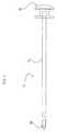
- FIG. 3illustrates an elevational view of a shaft portion of a trocar, in accordance with a sixth embodiment of the present invention
- FIG. 3Aillustrates a sectional view taken along line II-II of FIG. 3 , in accordance with a seventh embodiment of the present invention
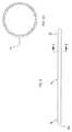
- FIG. 4illustrates an elevational view of a handle portion of a trocar, in accordance with an eighth embodiment of the present invention.
- FIG. 4Aillustrates a side view of a handle portion of a trocar, in accordance with a ninth embodiment of the present invention.
- FIG. 4Billustrates a bottom plan view of a handle portion of a trocar, in accordance with a tenth embodiment of the present invention
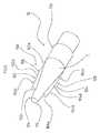
- FIG. 5illustrates a perspective view of a tip portion of a trocar, in accordance with an eleventh embodiment of the present invention
- FIG. 6illustrates a top plan view of a tip portion of a trocar, in accordance with a twelfth embodiment of the present invention
- FIG. 7illustrates an elevational view of a tip portion of a trocar, in accordance with a thirteenth embodiment of the present invention.
- FIG. 8illustrates a side view of a tip portion of a trocar, in accordance with a fourteenth embodiment of the present invention.
- FIG. 9illustrates a top plan view of a tip portion (with a portion thereof shown in section) of a trocar, in accordance with a fifteenth embodiment of the present invention.
- the trocar 10primarily includes, without limitation, a tip portion 12 , a shaft portion 14 , and a handle portion 16 . It should be appreciated that the trocar 10 of the present invention may be operable to interoperate with a cannula or similar device during a surgical procedure.
- the tip portion 12is shown as having a substantially cone-shaped distal portion 12 a , a substantially cylindrically-shaped intermediate (also referred to as an intermediate proximal portion) portion 12 b , and a substantially cylindrically-shaped proximal portion 12 c .
- the proximal portion 12 cmay be provided with a smaller diameter than the intermediate portion 12 b so as to form an annular shoulder portion 12 d , the intended purpose of which will be described herein.
- one or more portions of the tip portion 12are shown as being solid, it should be appreciated that one or more portions of the tip portion 12 may be at least partially hollow.
- the tip portion 12may be comprised of a biocompatible material, such as but not limited to stainless steel.
- the shaft portion 14is shown as being substantially cylindrical. Although one or more portions of the shaft portion 14 are shown as being hollow, it should be appreciated that one or more portions of the shaft portion 14 may be at least partially solid.
- the shaft portion 14may be preferably comprised of a biocompatible material, such as but not limited to stainless steel.
- the proximal portion 12 c of the tip portion 12may be received within and/or joined to a distal end portion 18 of shaft portion 14 by any number of methods including, but not limited to brazing and/or the like.
- the shoulder portion 12 d of the tip portion 12may abut against the end surface 18 a of the distal end portion 18 and act as a stop.
- the tip portion 12 and the shaft portion 14may be formed integrally together from a single piece of material.
- the handle portion 16is preferably comprised of a biocompatible material, such as but not limited to stainless steel.
- a proximal portion 22 of the shaft portion 14may be joined to the distal portion 16 a of the handle portion 16 by any number of methods including, but not limited to welding and/or the like.
- a recess 20may be formed in the distal portion 16 a of the handle portion 16 , wherein the proximal portion 22 of the shaft portion 14 may be received therein.
- the shaft portion 14 and the handle portion 16may be formed integrally together from a single piece of material.
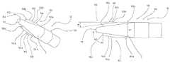
- the blade system 100may include two spaced and opposed wing members 102 , 104 , respectively.
- the wing members 102 , 104may be formed on the tip portion 12 by any number of methods, including but not limited to grinding and/or the like.
- Each of the wing members 102 , 104may include a first portion 102 a , 104 a , respectively, and a second portion 102 b , 104 b , respectively.
- the first portions 102 a , 104 amay extend in a substantially co-planar orientation relative to the intermediate portion 12 b of the tip portion 12 .
- the second portions 102 b , 104 bmay extend in a substantially angularly inwardly orientation towards the distal portion 12 a of the tip portion 12 .
- the second portions 102 b , 104 bat about points 106 , 108 , respectively, may begin to extend in a substantially angularly inwardly orientation towards the distal portion 12 a of the tip portion 12 .
- the cone portion C of the tip portion 12may taper inwardly towards the distal portion 12 a at an angle in the range of about 12-20°, more preferably in the range of about 14-18°, and an angle of about 16° being most preferred.
- the second portions 102 b , 104 bdo not have to extend all the way to the terminus 110 of the tip portion 12 ; but rather, they may terminate at a location prior to or short of the terminus 110 .
- first portions 102 a , 104 a , respectively, and the second portions 102 b , 104 b , respectively,is not thought to be critical to the operation of the present invention; however, an angle in the range of about 6-10° is preferred, an angle in the range of about 7-9° being more preferred, and an angle of about 8° being most preferred.
- the second portions 102 b , 104 bmay include areas defining a cutting edge 102 c , 104 c , respectively, and a blade edge 102 d , 104 d , respectively, that are selectively operable to cut through various bodily tissues so as to penetrate a patient's bodily cavities. That is, cutting edges 102 c , 104 c , respectively, and blade edges 102 d , 104 d , respectively, may be formed with areas of sufficient sharpness so as to penetrate and cut through tissue without undue effort by the surgeon.
- the angle formed by cutting edge 102 c and distal portion 108may be preferably in the range of about 94-102°, more preferably in the range of about 96-100°, and most preferably 98° Likewise, the angle formed by cutting edge 104 c and distal portion 108 may be preferably in the range of about 94-102°, more preferably in the range of about 96-100°, and most preferably 98°.
- the trocar 10 of the present inventionis comprised of materials that can be sterilized many times without any degradation of the materials, the trocar 10 , including its component parts thereof, is reposable and/or reusable and can thus be used for a relatively large number of surgical procedures, assuming conventional sterilization techniques are employed after each surgical procedure.
Landscapes
- Health & Medical Sciences (AREA)
- Surgery (AREA)
- Life Sciences & Earth Sciences (AREA)
- Biomedical Technology (AREA)
- Nuclear Medicine, Radiotherapy & Molecular Imaging (AREA)
- Engineering & Computer Science (AREA)
- Pathology (AREA)
- Heart & Thoracic Surgery (AREA)
- Medical Informatics (AREA)
- Molecular Biology (AREA)
- Animal Behavior & Ethology (AREA)
- General Health & Medical Sciences (AREA)
- Public Health (AREA)
- Veterinary Medicine (AREA)
- Surgical Instruments (AREA)
Abstract
Description
Claims (9)
Priority Applications (1)
| Application Number | Priority Date | Filing Date | Title |
|---|---|---|---|
| US13/294,474US8821526B2 (en) | 2010-11-11 | 2011-11-11 | Trocar |
Applications Claiming Priority (2)
| Application Number | Priority Date | Filing Date | Title |
|---|---|---|---|
| US41254510P | 2010-11-11 | 2010-11-11 | |
| US13/294,474US8821526B2 (en) | 2010-11-11 | 2011-11-11 | Trocar |
Publications (2)
| Publication Number | Publication Date |
|---|---|
| US20120123460A1 US20120123460A1 (en) | 2012-05-17 |
| US8821526B2true US8821526B2 (en) | 2014-09-02 |
Family
ID=46048496
Family Applications (1)
| Application Number | Title | Priority Date | Filing Date |
|---|---|---|---|
| US13/294,474ActiveUS8821526B2 (en) | 2010-11-11 | 2011-11-11 | Trocar |
Country Status (1)
| Country | Link |
|---|---|
| US (1) | US8821526B2 (en) |
Cited By (2)
| Publication number | Priority date | Publication date | Assignee | Title |
|---|---|---|---|---|
| US10022148B2 (en) | 2012-12-27 | 2018-07-17 | Covidien Lp | Two-shot molded optical obturator |
| US10543018B2 (en) | 2015-05-15 | 2020-01-28 | Covidien Lp | Surgical access device |
Families Citing this family (4)
| Publication number | Priority date | Publication date | Assignee | Title |
|---|---|---|---|---|
| USD737973S1 (en)* | 2014-04-03 | 2015-09-01 | Karl Storz Gmbh & Co. Kg | Trocar sleeve |
| CN104188713B (en)* | 2014-09-11 | 2016-12-07 | 常州健瑞宝医疗器械有限公司 | Puncturing lever and there is the perforator of described puncturing lever |
| USD800307S1 (en)* | 2016-02-25 | 2017-10-17 | BioTE Medical, LLC | Trocar |
| CN105919656A (en)* | 2016-06-27 | 2016-09-07 | 江苏风和医疗器材有限公司 | Puncture core sharp end, and puncture device and puncture core with puncture core sharp end |
Citations (78)
| Publication number | Priority date | Publication date | Assignee | Title |
|---|---|---|---|---|
| US5242412A (en) | 1992-01-21 | 1993-09-07 | Blake Joseph W Iii | Trocar tube subassembly having sealing ring and duckbill sealing tube having planar, truncate, diverging sealing bills |
| US5256149A (en) | 1992-02-14 | 1993-10-26 | Ethicon, Inc. | Trocar having transparent cannula and method of using |
| US5334150A (en) | 1992-11-17 | 1994-08-02 | Kaali Steven G | Visually directed trocar for laparoscopic surgical procedures and method of using same |
| US5364372A (en)* | 1993-03-29 | 1994-11-15 | Endoscopic Concepts, Inc. | Trocar and cannula |
| US5366445A (en) | 1993-03-30 | 1994-11-22 | Habley Medical Technology Corp. | Trocar with rotating safety shield |
| US5385572A (en) | 1992-11-12 | 1995-01-31 | Beowulf Holdings | Trocar for endoscopic surgery |
| US5387197A (en)* | 1993-02-25 | 1995-02-07 | Ethicon, Inc. | Trocar safety shield locking mechanism |
| US5387196A (en) | 1992-05-19 | 1995-02-07 | United States Surgical Corporation | Cannula assembly having conductive cannula |
| EP0665029A2 (en) | 1994-01-27 | 1995-08-02 | Sheridan Catheter Corp. | Esophageal-tracheal double lumen airway |
| US5441041A (en) | 1993-09-13 | 1995-08-15 | United States Surgical Corporation | Optical trocar |
| US5449370A (en) | 1993-05-12 | 1995-09-12 | Ethicon, Inc. | Blunt tipped ultrasonic trocar |
| US5467762A (en) | 1993-09-13 | 1995-11-21 | United States Surgical Corporation | Optical trocar |
| US5545150A (en) | 1994-05-06 | 1996-08-13 | Endoscopic Concepts, Inc. | Trocar |
| US5569292A (en) | 1995-02-01 | 1996-10-29 | Ethicon Endo-Surgery, Inc. | Surgical penetration instrument with transparent blades and tip cover |
| US5569291A (en) | 1995-02-01 | 1996-10-29 | Ethicon Endo-Surgery, Inc. | Surgical penetration and dissection instrument |
| US5591192A (en)* | 1995-02-01 | 1997-01-07 | Ethicon Endo-Surgery, Inc. | Surgical penetration instrument including an imaging element |
| US5603702A (en) | 1994-08-08 | 1997-02-18 | United States Surgical Corporation | Valve system for cannula assembly |
| US5620456A (en) | 1995-10-20 | 1997-04-15 | Lasersurge, Inc. | Trocar assembly |
| US5697913A (en) | 1996-08-09 | 1997-12-16 | Ethicon Endo-Surgery, Inc. | Trocar including cannula with stepped region |
| US5709671A (en) | 1995-10-16 | 1998-01-20 | Ethicon Endo-Surgery, Inc. | Trocar having an improved tip configuration |
| US5738628A (en) | 1995-03-24 | 1998-04-14 | Ethicon Endo-Surgery, Inc. | Surgical dissector and method for its use |
| US5817061A (en) | 1997-05-16 | 1998-10-06 | Ethicon Endo-Surgery, Inc. | Trocar assembly |
| US5860996A (en) | 1994-05-26 | 1999-01-19 | United States Surgical Corporation | Optical trocar |
| US5868714A (en) | 1996-09-16 | 1999-02-09 | Endoscopic Concepts, Inc. | Trocar reducer system |
| US5904699A (en) | 1997-09-19 | 1999-05-18 | Ethicon Endo-Surgery, Inc. | Trocar for penetration and skin incision |
| US5916232A (en) | 1997-10-10 | 1999-06-29 | Applied Medical Resources Corporation | Asymmetrical obturator |
| US5957947A (en) | 1997-07-18 | 1999-09-28 | Wattiez; Arnaud | Single use trocar assembly |
| US5957888A (en) | 1995-10-10 | 1999-09-28 | United States Surgical Corporation | Surgical cannula having a variable length |
| US5980493A (en) | 1995-10-20 | 1999-11-09 | United States Surgical Corporation | Modular trocar system and methods and assembly |
| US5984908A (en) | 1997-04-10 | 1999-11-16 | Chase Medical Inc | Venous return catheter having integral support member |
| US6017356A (en) | 1997-09-19 | 2000-01-25 | Ethicon Endo-Surgery Inc. | Method for using a trocar for penetration and skin incision |
| US6228061B1 (en) | 1998-02-03 | 2001-05-08 | Imagyn Medical Technologies California, Inc. | Trocar seal system having dual seals |
| US6319266B1 (en) | 2000-03-16 | 2001-11-20 | United States Surgical Corporation | Trocar system and method of use |
| US6371967B1 (en) | 1997-06-30 | 2002-04-16 | Ethicon Endo-Surgery, Inc. | Inductively coupled electrosurgical instrument |
| US20020072713A1 (en) | 2000-05-24 | 2002-06-13 | Surgical Innovations Ltd. | Surgical seal |
| US6656198B2 (en) | 2001-06-01 | 2003-12-02 | Ethicon-Endo Surgery, Inc. | Trocar with reinforced obturator shaft |
| US6666846B1 (en) | 1999-11-12 | 2003-12-23 | Edwards Lifesciences Corporation | Medical device introducer and obturator and methods of use |
| US6702787B2 (en) | 1997-05-02 | 2004-03-09 | Tyco Healthcare Group Lp | Trocar seal system |
| DE10333956A1 (en) | 2003-07-25 | 2005-02-17 | Richard Wolf Gmbh | Viewing obturator, comprising removable inner shaft with transparent penetration tip |
| US20050070850A1 (en) | 2003-09-30 | 2005-03-31 | Albrecht Thomas E. | Low-profile, recessed stop-cock valve for trocar assembly |
| US20050070947A1 (en) | 2003-09-30 | 2005-03-31 | Franer Paul T. | Rotational latching system for a trocar |
| US20050149096A1 (en) | 2003-12-23 | 2005-07-07 | Hilal Said S. | Catheter with conduit traversing tip |
| US6923783B2 (en) | 2000-02-25 | 2005-08-02 | United States Surgical Corporation | Valve assembly |
| US20050203559A1 (en)* | 2004-03-11 | 2005-09-15 | O'heeron Peter T. | Obturator tip |
| US7025747B2 (en) | 2000-10-13 | 2006-04-11 | Tyco Healthcare Group Lp | Valve assembly including diameter reduction structure for trocar |
| US20060173479A1 (en) | 2005-01-28 | 2006-08-03 | Smith Robert C | Optical penetrating adapter for surgical portal |
| EP1707132A2 (en) | 2005-03-31 | 2006-10-04 | Tyco Healthcare Group Lp | Optical obturator |
| US20060264992A1 (en) | 2003-09-30 | 2006-11-23 | Ethicon Endo-Surgery, Inc. | Button latching system for a trocar |
| US20070010842A1 (en) | 2003-06-22 | 2007-01-11 | Sergey Popov | Safety trocar obturator |
| US20070088277A1 (en) | 2005-10-14 | 2007-04-19 | Applied Medical Resources Corporation | Surgical access port |
| US20070093851A1 (en) | 2003-06-13 | 2007-04-26 | Koninklijke Philips Electronics N.V. | Surgical seal |
| USD542918S1 (en) | 2005-02-08 | 2007-05-15 | Ethicon Endo-Surgery, Inc. | Trocar |
| US20070185453A1 (en) | 2003-03-21 | 2007-08-09 | Michael Cropper S | Conical trocar seal |
| US20070251361A1 (en)* | 2006-04-28 | 2007-11-01 | Crystal Glass Canada Ltd. | Windshield removal assembly, method and blade for same |
| US20070260275A1 (en) | 2006-05-03 | 2007-11-08 | Applied Medical Resources Corporation | Flat blade shielded obturator |
| US20070260273A1 (en) | 2006-05-08 | 2007-11-08 | Ethicon Endo-Surgery, Inc. | Endoscopic Translumenal Surgical Systems |
| US20080086074A1 (en)* | 2006-10-06 | 2008-04-10 | Applied Medical Presources Corporation | Visual insufflation port |
| US20080294184A1 (en) | 2007-05-22 | 2008-11-27 | Tyco Healthcare Group Lp | Access sheath with blade |
| US20090093833A1 (en) | 2007-10-05 | 2009-04-09 | Tyco Healthcare Group Lp | Bladeless obturator for use in a surgical trocar assembly |
| US7585288B2 (en) | 2004-01-23 | 2009-09-08 | Genico, Inc. | Trocar and cannula assembly having conical valve and related methods |
| US7597701B2 (en) | 2003-09-30 | 2009-10-06 | Ethican Endo-Surgery, Inc. | Instrument lock assembly for trocar |
| US20090270817A1 (en) | 2008-04-28 | 2009-10-29 | Ethicon Endo-Surgery, Inc. | Fluid removal in a surgical access device |
| US20090281386A1 (en) | 2006-04-19 | 2009-11-12 | Acosta Pablo G | Devices, system and methods for minimally invasive abdominal surgical procedures |
| US20090281376A1 (en) | 2006-04-19 | 2009-11-12 | Acosta Pablo G | Devices, system and methods for minimally invasive abdominal surgical procedures |
| US20090281500A1 (en) | 2006-04-19 | 2009-11-12 | Acosta Pablo G | Devices, system and methods for minimally invasive abdominal surgical procedures |
| US20090281498A1 (en) | 2006-04-19 | 2009-11-12 | Acosta Pablo G | Devices, system and methods for minimally invasive abdominal surgical procedures |
| US7637896B2 (en) | 2005-03-30 | 2009-12-29 | Ethicon Endo-Surgery, Inc. | Obturator tip assembly for a trocar |
| US20100016664A1 (en) | 2006-12-20 | 2010-01-21 | Tyco Healthcare Group Lp | Surgical visual obturator |
| US20100022959A1 (en) | 2006-08-25 | 2010-01-28 | Stuart Moran | Cannula sealing apparatus |
| US7686823B2 (en) | 2001-09-24 | 2010-03-30 | Applied Medical Resources, Corporation | Bladeless obturator |
| US20100081988A1 (en) | 2008-09-29 | 2010-04-01 | Applies Medical Resources Corporation | First-entry trocar system |
| US20100137895A1 (en) | 2007-04-17 | 2010-06-03 | Smith Robert C | Visual obturator with handle |
| US7758603B2 (en) | 2002-05-16 | 2010-07-20 | Applied Medical Resources Corporation | Blunt tip obturator |
| US7794644B2 (en) | 2005-10-05 | 2010-09-14 | Applied Medical Resources Corporation | Thin-walled optical obturator |
| US7824327B2 (en) | 2005-04-12 | 2010-11-02 | Tyco Healthcare Group Llp | Optical trocar with scope holding assembly |
| US7918826B2 (en) | 2007-09-14 | 2011-04-05 | Ethicon Endo-Surgery, Inc. | Trocar assembly |
| US7947058B2 (en) | 2001-09-24 | 2011-05-24 | Applied Medical Resources Corporation | Bladeless optical obturator |
| US7967791B2 (en) | 2007-07-23 | 2011-06-28 | Ethicon Endo-Surgery, Inc. | Surgical access device |
- 2011
- 2011-11-11USUS13/294,474patent/US8821526B2/enactiveActive
Patent Citations (97)
| Publication number | Priority date | Publication date | Assignee | Title |
|---|---|---|---|---|
| US5242412A (en) | 1992-01-21 | 1993-09-07 | Blake Joseph W Iii | Trocar tube subassembly having sealing ring and duckbill sealing tube having planar, truncate, diverging sealing bills |
| JPH07250810A (en) | 1992-02-14 | 1995-10-03 | Ethicon Inc | Trocar with transparent cannula and how to use |
| US5256149A (en) | 1992-02-14 | 1993-10-26 | Ethicon, Inc. | Trocar having transparent cannula and method of using |
| US5387196A (en) | 1992-05-19 | 1995-02-07 | United States Surgical Corporation | Cannula assembly having conductive cannula |
| US5385572A (en) | 1992-11-12 | 1995-01-31 | Beowulf Holdings | Trocar for endoscopic surgery |
| US5334150A (en) | 1992-11-17 | 1994-08-02 | Kaali Steven G | Visually directed trocar for laparoscopic surgical procedures and method of using same |
| US5376076A (en) | 1992-11-17 | 1994-12-27 | Kaali; Steven G. | Visually directed trocar for laparoscopic surgical procedures and method of using same |
| US5380291A (en) | 1992-11-17 | 1995-01-10 | Kaali; Steven G. | Visually directed trocar for laparoscopic surgical procedures and method of using same |
| US5387197A (en)* | 1993-02-25 | 1995-02-07 | Ethicon, Inc. | Trocar safety shield locking mechanism |
| US5364372A (en)* | 1993-03-29 | 1994-11-15 | Endoscopic Concepts, Inc. | Trocar and cannula |
| US5366445A (en) | 1993-03-30 | 1994-11-22 | Habley Medical Technology Corp. | Trocar with rotating safety shield |
| US5449370A (en) | 1993-05-12 | 1995-09-12 | Ethicon, Inc. | Blunt tipped ultrasonic trocar |
| US6685630B2 (en) | 1993-09-13 | 2004-02-03 | United States Surgical Corporation | Optical trocar |
| US5441041A (en) | 1993-09-13 | 1995-08-15 | United States Surgical Corporation | Optical trocar |
| US5467762A (en) | 1993-09-13 | 1995-11-21 | United States Surgical Corporation | Optical trocar |
| US7322933B2 (en) | 1993-09-13 | 2008-01-29 | United States Surgical Corporation | Optical trocar |
| US5658236A (en) | 1993-09-13 | 1997-08-19 | United States Surgical Corporation | Optical trocar |
| US5569160A (en) | 1993-09-13 | 1996-10-29 | United States Surgical Corporation | Optical trocar |
| US5499625A (en) | 1994-01-27 | 1996-03-19 | The Kendall Company | Esophageal-tracheal double lumen airway |
| EP0665029A2 (en) | 1994-01-27 | 1995-08-02 | Sheridan Catheter Corp. | Esophageal-tracheal double lumen airway |
| US6063099A (en) | 1994-05-06 | 2000-05-16 | Endoscopic Concepts, Inc. | Dilating trocar shield with blade tip |
| US5607440A (en) | 1994-05-06 | 1997-03-04 | Endoscopic Concepts, Inc. | Trocar with lockable shield |
| US5545150A (en) | 1994-05-06 | 1996-08-13 | Endoscopic Concepts, Inc. | Trocar |
| US5797943A (en) | 1994-05-06 | 1998-08-25 | Endoscopic Concepts, Inc. | Shielded trocar and trocar shield |
| US5860996A (en) | 1994-05-26 | 1999-01-19 | United States Surgical Corporation | Optical trocar |
| US5603702A (en) | 1994-08-08 | 1997-02-18 | United States Surgical Corporation | Valve system for cannula assembly |
| US5895377A (en) | 1994-08-08 | 1999-04-20 | United States Surgical Corporation | Valve system for cannula assembly |
| US5569291A (en) | 1995-02-01 | 1996-10-29 | Ethicon Endo-Surgery, Inc. | Surgical penetration and dissection instrument |
| US5591192A (en)* | 1995-02-01 | 1997-01-07 | Ethicon Endo-Surgery, Inc. | Surgical penetration instrument including an imaging element |
| US5569292A (en) | 1995-02-01 | 1996-10-29 | Ethicon Endo-Surgery, Inc. | Surgical penetration instrument with transparent blades and tip cover |
| US5738628A (en) | 1995-03-24 | 1998-04-14 | Ethicon Endo-Surgery, Inc. | Surgical dissector and method for its use |
| US5957888A (en) | 1995-10-10 | 1999-09-28 | United States Surgical Corporation | Surgical cannula having a variable length |
| US5709671A (en) | 1995-10-16 | 1998-01-20 | Ethicon Endo-Surgery, Inc. | Trocar having an improved tip configuration |
| US5620456A (en) | 1995-10-20 | 1997-04-15 | Lasersurge, Inc. | Trocar assembly |
| US5980493A (en) | 1995-10-20 | 1999-11-09 | United States Surgical Corporation | Modular trocar system and methods and assembly |
| US5697913A (en) | 1996-08-09 | 1997-12-16 | Ethicon Endo-Surgery, Inc. | Trocar including cannula with stepped region |
| US5868714A (en) | 1996-09-16 | 1999-02-09 | Endoscopic Concepts, Inc. | Trocar reducer system |
| US5984908A (en) | 1997-04-10 | 1999-11-16 | Chase Medical Inc | Venous return catheter having integral support member |
| US6702787B2 (en) | 1997-05-02 | 2004-03-09 | Tyco Healthcare Group Lp | Trocar seal system |
| US5817061A (en) | 1997-05-16 | 1998-10-06 | Ethicon Endo-Surgery, Inc. | Trocar assembly |
| US6371967B1 (en) | 1997-06-30 | 2002-04-16 | Ethicon Endo-Surgery, Inc. | Inductively coupled electrosurgical instrument |
| US5957947A (en) | 1997-07-18 | 1999-09-28 | Wattiez; Arnaud | Single use trocar assembly |
| US6017356A (en) | 1997-09-19 | 2000-01-25 | Ethicon Endo-Surgery Inc. | Method for using a trocar for penetration and skin incision |
| US5904699A (en) | 1997-09-19 | 1999-05-18 | Ethicon Endo-Surgery, Inc. | Trocar for penetration and skin incision |
| US5916232A (en) | 1997-10-10 | 1999-06-29 | Applied Medical Resources Corporation | Asymmetrical obturator |
| US6228061B1 (en) | 1998-02-03 | 2001-05-08 | Imagyn Medical Technologies California, Inc. | Trocar seal system having dual seals |
| US6666846B1 (en) | 1999-11-12 | 2003-12-23 | Edwards Lifesciences Corporation | Medical device introducer and obturator and methods of use |
| US6923783B2 (en) | 2000-02-25 | 2005-08-02 | United States Surgical Corporation | Valve assembly |
| US7559918B2 (en) | 2000-02-25 | 2009-07-14 | Joseph Pasqualucci | Valve assembly |
| US6319266B1 (en) | 2000-03-16 | 2001-11-20 | United States Surgical Corporation | Trocar system and method of use |
| US7367960B2 (en) | 2000-03-16 | 2008-05-06 | United States Surgical Corporation | Trocar system and method of use |
| US20020072713A1 (en) | 2000-05-24 | 2002-06-13 | Surgical Innovations Ltd. | Surgical seal |
| US7722570B2 (en) | 2000-05-24 | 2010-05-25 | Applied Medical Resources Corporation | Surgical seal |
| US7025747B2 (en) | 2000-10-13 | 2006-04-11 | Tyco Healthcare Group Lp | Valve assembly including diameter reduction structure for trocar |
| US6656198B2 (en) | 2001-06-01 | 2003-12-02 | Ethicon-Endo Surgery, Inc. | Trocar with reinforced obturator shaft |
| US7686823B2 (en) | 2001-09-24 | 2010-03-30 | Applied Medical Resources, Corporation | Bladeless obturator |
| US7947058B2 (en) | 2001-09-24 | 2011-05-24 | Applied Medical Resources Corporation | Bladeless optical obturator |
| US7758603B2 (en) | 2002-05-16 | 2010-07-20 | Applied Medical Resources Corporation | Blunt tip obturator |
| US20070185453A1 (en) | 2003-03-21 | 2007-08-09 | Michael Cropper S | Conical trocar seal |
| US20070093851A1 (en) | 2003-06-13 | 2007-04-26 | Koninklijke Philips Electronics N.V. | Surgical seal |
| US20070010842A1 (en) | 2003-06-22 | 2007-01-11 | Sergey Popov | Safety trocar obturator |
| DE10333956A1 (en) | 2003-07-25 | 2005-02-17 | Richard Wolf Gmbh | Viewing obturator, comprising removable inner shaft with transparent penetration tip |
| US20060264992A1 (en) | 2003-09-30 | 2006-11-23 | Ethicon Endo-Surgery, Inc. | Button latching system for a trocar |
| US7597701B2 (en) | 2003-09-30 | 2009-10-06 | Ethican Endo-Surgery, Inc. | Instrument lock assembly for trocar |
| US20050070947A1 (en) | 2003-09-30 | 2005-03-31 | Franer Paul T. | Rotational latching system for a trocar |
| US20050070850A1 (en) | 2003-09-30 | 2005-03-31 | Albrecht Thomas E. | Low-profile, recessed stop-cock valve for trocar assembly |
| US20050149096A1 (en) | 2003-12-23 | 2005-07-07 | Hilal Said S. | Catheter with conduit traversing tip |
| US7585288B2 (en) | 2004-01-23 | 2009-09-08 | Genico, Inc. | Trocar and cannula assembly having conical valve and related methods |
| US7320694B2 (en) | 2004-03-11 | 2008-01-22 | Coopersurgical, Inc. | Obturator tip |
| US20050203559A1 (en)* | 2004-03-11 | 2005-09-15 | O'heeron Peter T. | Obturator tip |
| US20060173479A1 (en) | 2005-01-28 | 2006-08-03 | Smith Robert C | Optical penetrating adapter for surgical portal |
| USD542918S1 (en) | 2005-02-08 | 2007-05-15 | Ethicon Endo-Surgery, Inc. | Trocar |
| US7637896B2 (en) | 2005-03-30 | 2009-12-29 | Ethicon Endo-Surgery, Inc. | Obturator tip assembly for a trocar |
| US7470230B2 (en) | 2005-03-31 | 2008-12-30 | Tyco Healthcare Group Lp | Optical obturator |
| US20090076323A1 (en) | 2005-03-31 | 2009-03-19 | Tyco Healthcare Group Lp | Optical obturator |
| EP1707132A2 (en) | 2005-03-31 | 2006-10-04 | Tyco Healthcare Group Lp | Optical obturator |
| US7824327B2 (en) | 2005-04-12 | 2010-11-02 | Tyco Healthcare Group Llp | Optical trocar with scope holding assembly |
| US7794644B2 (en) | 2005-10-05 | 2010-09-14 | Applied Medical Resources Corporation | Thin-walled optical obturator |
| US20070088277A1 (en) | 2005-10-14 | 2007-04-19 | Applied Medical Resources Corporation | Surgical access port |
| US20090281386A1 (en) | 2006-04-19 | 2009-11-12 | Acosta Pablo G | Devices, system and methods for minimally invasive abdominal surgical procedures |
| US20090281376A1 (en) | 2006-04-19 | 2009-11-12 | Acosta Pablo G | Devices, system and methods for minimally invasive abdominal surgical procedures |
| US20090281500A1 (en) | 2006-04-19 | 2009-11-12 | Acosta Pablo G | Devices, system and methods for minimally invasive abdominal surgical procedures |
| US20090281498A1 (en) | 2006-04-19 | 2009-11-12 | Acosta Pablo G | Devices, system and methods for minimally invasive abdominal surgical procedures |
| US20070251361A1 (en)* | 2006-04-28 | 2007-11-01 | Crystal Glass Canada Ltd. | Windshield removal assembly, method and blade for same |
| US20070260275A1 (en) | 2006-05-03 | 2007-11-08 | Applied Medical Resources Corporation | Flat blade shielded obturator |
| US20080051735A1 (en) | 2006-05-08 | 2008-02-28 | Ethicon Endo-Surgery, Inc. | Endoscopic translumenal surgical systems |
| US20070260273A1 (en) | 2006-05-08 | 2007-11-08 | Ethicon Endo-Surgery, Inc. | Endoscopic Translumenal Surgical Systems |
| US20100022959A1 (en) | 2006-08-25 | 2010-01-28 | Stuart Moran | Cannula sealing apparatus |
| US20080086074A1 (en)* | 2006-10-06 | 2008-04-10 | Applied Medical Presources Corporation | Visual insufflation port |
| US20100016664A1 (en) | 2006-12-20 | 2010-01-21 | Tyco Healthcare Group Lp | Surgical visual obturator |
| US20100137895A1 (en) | 2007-04-17 | 2010-06-03 | Smith Robert C | Visual obturator with handle |
| US20080294184A1 (en) | 2007-05-22 | 2008-11-27 | Tyco Healthcare Group Lp | Access sheath with blade |
| US7967791B2 (en) | 2007-07-23 | 2011-06-28 | Ethicon Endo-Surgery, Inc. | Surgical access device |
| US7918826B2 (en) | 2007-09-14 | 2011-04-05 | Ethicon Endo-Surgery, Inc. | Trocar assembly |
| US20090093833A1 (en) | 2007-10-05 | 2009-04-09 | Tyco Healthcare Group Lp | Bladeless obturator for use in a surgical trocar assembly |
| US20090270817A1 (en) | 2008-04-28 | 2009-10-29 | Ethicon Endo-Surgery, Inc. | Fluid removal in a surgical access device |
| US20100081988A1 (en) | 2008-09-29 | 2010-04-01 | Applies Medical Resources Corporation | First-entry trocar system |
Non-Patent Citations (2)
| Title |
|---|
| English Abstract of DE10333956. |
| English Abstract of JP7250810. |
Cited By (5)
| Publication number | Priority date | Publication date | Assignee | Title |
|---|---|---|---|---|
| US10022148B2 (en) | 2012-12-27 | 2018-07-17 | Covidien Lp | Two-shot molded optical obturator |
| US10792068B2 (en) | 2012-12-27 | 2020-10-06 | Covidien Lp | Method of manufacturing a two-shot molded optical obturator |
| US11278315B2 (en) | 2012-12-27 | 2022-03-22 | Covidien Lp | Method of manufacturing an obturator |
| US10543018B2 (en) | 2015-05-15 | 2020-01-28 | Covidien Lp | Surgical access device |
| US11832849B2 (en) | 2015-05-15 | 2023-12-05 | Covidien Lp | Surgical access device |
Also Published As
| Publication number | Publication date |
|---|---|
| US20120123460A1 (en) | 2012-05-17 |
Similar Documents
| Publication | Publication Date | Title |
|---|---|---|
| US8821526B2 (en) | Trocar | |
| US6835201B2 (en) | Trocar | |
| US6830578B2 (en) | Trocar | |
| US20080234713A1 (en) | Shaver blade with depth markings | |
| EP2272555B1 (en) | Surgical instrument | |
| US8956326B2 (en) | Obturator tips | |
| EP2380512B1 (en) | Obturator tips | |
| US20050033304A1 (en) | Obturator tip for a trocar | |
| US9131951B2 (en) | Endoscopic surgical blade and method of use thereof | |
| EP2324782A1 (en) | Port fixation device | |
| EP2978375B1 (en) | Tunnel gage | |
| US9888936B2 (en) | Device and methods for use during arthroscopic surgery | |
| US20190038306A1 (en) | Minimally invasive incision instrument having a guided cutting apparatus for multiple use | |
| US20100100046A1 (en) | Cannulated apertured grooved director | |
| US8070689B2 (en) | Perforating trocar | |
| EP3054869B1 (en) | Integrated uterine manipulator and sensor | |
| US8956284B2 (en) | Minimally invasive retractor and posted screw | |
| EP2449988A1 (en) | Wound closure device including suction step sleeve | |
| CN209916231U (en) | Guide sleeve and surgical instrument | |
| US20110306998A1 (en) | Trocar system | |
| CN209966529U (en) | Instruments for spine surgery | |
| KR102032510B1 (en) | Medical Trcar | |
| US9186173B2 (en) | Optical obturator system | |
| JP3124260U (en) | Endoscopic surgery scissors | |
| JP3737540B2 (en) | Trocar mantle and trocar |
Legal Events
| Date | Code | Title | Description |
|---|---|---|---|
| AS | Assignment | Owner name:AMERICAN ENDOSCOPY SERVICES, INC., TENNESSEE Free format text:ASSIGNMENT OF ASSIGNORS INTEREST;ASSIGNORS:WINFREE, ALAN;ASHBURN, STANLEY;HENRY, ROBERT;REEL/FRAME:028256/0192 Effective date:20101230 | |
| AS | Assignment | Owner name:SPECIALTYCARE, INC, TENNESSEE Free format text:ASSIGNMENT OF ASSIGNORS INTEREST;ASSIGNOR:AMERICAN ENDOSCOPY SERVICES, INC.;REEL/FRAME:028266/0023 Effective date:20120430 | |
| AS | Assignment | Owner name:REGIONS BANK, AS ADMINISTRATIVE AGENT, TENNESSEE Free format text:SECURITY AGREEMENT;ASSIGNOR:SPECIALTYCARE, INC.;REEL/FRAME:029559/0741 Effective date:20121231 | |
| STCF | Information on status: patent grant | Free format text:PATENTED CASE | |
| FEPP | Fee payment procedure | Free format text:PAYOR NUMBER ASSIGNED (ORIGINAL EVENT CODE: ASPN); ENTITY STATUS OF PATENT OWNER: LARGE ENTITY | |
| AS | Assignment | Owner name:ANTARES CAPITAL LP, AS AGENT, ILLINOIS Free format text:PATENT SECURITY AGREEMENT (2L);ASSIGNOR:SPECIALTYCARE, INC.;REEL/FRAME:043747/0373 Effective date:20170901 Owner name:ANTARES CAPITAL LP, AS AGENT, ILLINOIS Free format text:TRADEMARK SECURITY AGREEMENT (1L);ASSIGNOR:SPECIALTYCARE, INC.;REEL/FRAME:043747/0351 Effective date:20170901 | |
| MAFP | Maintenance fee payment | Free format text:PAYMENT OF MAINTENANCE FEE, 4TH YEAR, LARGE ENTITY (ORIGINAL EVENT CODE: M1551) Year of fee payment:4 | |
| AS | Assignment | Owner name:ANTARES CAPITAL LP, AS COLLATERAL AGENT, ILLINOIS Free format text:SECURITY INTEREST;ASSIGNOR:SPECIALTYCARE, INC.;REEL/FRAME:056590/0403 Effective date:20210618 Owner name:SPECIALTYCARE, INC., TENNESSEE Free format text:RELEASE OF SECURITY INTEREST IN INTELLECTUAL PROPERTY (1L);ASSIGNOR:ANTARES CAPITAL LP, AS AGENT;REEL/FRAME:056627/0845 Effective date:20210618 | |
| AS | Assignment | Owner name:SPECIALTYCARE, INC., TENNESSEE Free format text:RELEASE OF SECURITY INTEREST IN INTELLECTUAL PROPERTY COLLATERAL (2L);ASSIGNOR:ANTARES CAPITAL LP, AS AGENT;REEL/FRAME:056628/0504 Effective date:20210618 | |
| MAFP | Maintenance fee payment | Free format text:PAYMENT OF MAINTENANCE FEE, 8TH YEAR, LARGE ENTITY (ORIGINAL EVENT CODE: M1552); ENTITY STATUS OF PATENT OWNER: LARGE ENTITY Year of fee payment:8 |