US8821524B2 - Feedback control of on/off pneumatic actuators - Google Patents
Feedback control of on/off pneumatic actuatorsDownload PDFInfo
- Publication number
- US8821524B2 US8821524B2US12/788,609US78860910AUS8821524B2US 8821524 B2US8821524 B2US 8821524B2US 78860910 AUS78860910 AUS 78860910AUS 8821524 B2US8821524 B2US 8821524B2
- Authority
- US
- United States
- Prior art keywords
- pressure
- pneumatic
- time
- actual
- length
- Prior art date
- Legal status (The legal status is an assumption and is not a legal conclusion. Google has not performed a legal analysis and makes no representation as to the accuracy of the status listed.)
- Active, expires
Links
Images


Classifications
- A61B19/0248—
- A—HUMAN NECESSITIES
- A61—MEDICAL OR VETERINARY SCIENCE; HYGIENE
- A61B—DIAGNOSIS; SURGERY; IDENTIFICATION
- A61B50/00—Containers, covers, furniture or holders specially adapted for surgical or diagnostic appliances or instruments, e.g. sterile covers
- A61B50/10—Furniture specially adapted for surgical or diagnostic appliances or instruments
- A61B50/13—Trolleys, e.g. carts
- A—HUMAN NECESSITIES
- A61—MEDICAL OR VETERINARY SCIENCE; HYGIENE
- A61F—FILTERS IMPLANTABLE INTO BLOOD VESSELS; PROSTHESES; DEVICES PROVIDING PATENCY TO, OR PREVENTING COLLAPSING OF, TUBULAR STRUCTURES OF THE BODY, e.g. STENTS; ORTHOPAEDIC, NURSING OR CONTRACEPTIVE DEVICES; FOMENTATION; TREATMENT OR PROTECTION OF EYES OR EARS; BANDAGES, DRESSINGS OR ABSORBENT PADS; FIRST-AID KITS
- A61F9/00—Methods or devices for treatment of the eyes; Devices for putting in contact-lenses; Devices to correct squinting; Apparatus to guide the blind; Protective devices for the eyes, carried on the body or in the hand
- A61F9/007—Methods or devices for eye surgery
- A61F9/00736—Instruments for removal of intra-ocular material or intra-ocular injection, e.g. cataract instruments
- A61F9/00763—Instruments for removal of intra-ocular material or intra-ocular injection, e.g. cataract instruments with rotating or reciprocating cutting elements, e.g. concentric cutting needles
- A—HUMAN NECESSITIES
- A61—MEDICAL OR VETERINARY SCIENCE; HYGIENE
- A61B—DIAGNOSIS; SURGERY; IDENTIFICATION
- A61B17/00—Surgical instruments, devices or methods
- A61B2017/00017—Electrical control of surgical instruments
- A61B2017/00137—Details of operation mode
- A61B2017/00154—Details of operation mode pulsed
- A—HUMAN NECESSITIES
- A61—MEDICAL OR VETERINARY SCIENCE; HYGIENE
- A61B—DIAGNOSIS; SURGERY; IDENTIFICATION
- A61B17/00—Surgical instruments, devices or methods
- A61B2017/00535—Surgical instruments, devices or methods pneumatically or hydraulically operated
- A61B2017/00544—Surgical instruments, devices or methods pneumatically or hydraulically operated pneumatically
- A61B2019/025—
Definitions
- the present inventionpertains to pneumatic actuators. More particularly, but not by way of limitation, the present invention pertains to feedback control of on/off pneumatic actuators usable with a vitrectomy probe.
- Microsurgical proceduresfrequently require precision cutting and/or removing various body tissues.
- certain ophthalmic surgical proceduresrequire cutting and removing portions of the vitreous humor, a transparent jelly-like material that fills the posterior segment of the eye.
- the vitreous humor, or vitreousis composed of numerous microscopic fibrils that are often attached to the retina. Therefore, cutting and removing the vitreous must be done with great care to avoid traction on the retina, the separation of the retina from the choroid, a retinal tear, or, in the worst case, cutting and removal of the retina itself.
- delicate operationssuch as mobile tissue management (e.g. cutting and removal of vitreous near a detached portion of the retina or a retinal tear), vitreous base dissection, and cutting and removal of membranes are particularly difficult.
- microsurgical cutting probesin posterior segment ophthalmic surgery is well known.
- These cutting probestypically include a hollow outer cutting member, a hollow inner cutting member arranged coaxially with and movably disposed within the hollow outer cutting member, and a port extending radially through the outer cutting member near the distal end thereof.
- Vitreous humor and/or membranesare aspirated into the open port, and the inner member is actuated, closing the port.
- cutting surfaces on both the inner and outer cutting memberscooperate to cut the vitreous and/or membranes, and the cut tissue is then aspirated away through the inner cutting member.
- cutting rates and duty cycleare frequently controlled to regulate the amount of tissue that can be cut in a given time period.
- the cuttingmay be done in a manner that lends to efficiency.
- the cuttingmay be done in a careful manner, where the amount of tissue cut per cutting cycle is decreased. This is accomplished by controlling the duty cycle, or the percentage of time in a cutting cycle that a port is open. This is determined by dividing the amount of time the port is open by the total amount of time of a single cutting cycle. Larger duty cycles provide for efficient cutting while smaller duty cycles provide for slow and careful cutting.
- vitrectomy probesthat compensate for discrepancies arising from initial tolerances or degradations of components over time.
- the present disclosureis directed to addressing one or more of the deficiencies in the prior art.
- the present disclosureis directed to a surgical system having feedback control for pneumatic actuators.
- the systemincludes a pneumatic pressure source and a vitrectomy cutter having a cutting mechanism, a first pneumatic input port, and a second pneumatic input port.
- a pneumatic actuatoris configured to direct pneumatic pressure to one of the first and second pneumatic input ports.
- a first pressure transduceris located and configured to detect actual pressure at the first pneumatic input port, and a second pressure transducer is located and configured to detect actual pressure at the second pneumatic input port.
- a controllercommunicates with the first and second pressure transducers and the pneumatic actuator. It is configured to change the pneumatic actuator actuation timing based on the data communicated from the first and second pressure transducers.
- the present disclosureis directed to a method of controlling a surgical system using feedback control for pneumatic actuators.
- the methodincludes steps of selectively directing pneumatic pressure to one of first and second pneumatic input ports on a vitrectomy cutter, detecting actual pressure at the first pneumatic input port with a first pressure transducer, and detecting actual pressure at the second pneumatic input port with a second pressure transducer.
- the methodalso includes modifying actuation timing of the pneumatic actuator based on the actual pressures detected by the first and second pressure transducers.
- the present disclosureis directed to a surgical system having feedback control for pneumatic actuators. It includes a pneumatic pressure source and a vitrectomy cutter having a cutting mechanism, a first pneumatic input port, and a second pneumatic input port.
- a pneumatic actuatordirects pneumatic pressure to one of the first and second pneumatic input ports.
- a first pressure transduceris placed and configured to detect pressure at the first pneumatic input port, and a second pressure transducer placed and configured to detect pressure at the second pneumatic input port.
- a controllercommunicates with the first and second pressure transducers and the pneumatic actuator. The controller is configured to compare the parameter data based on actual measured data to stored desired data and calculate a margin based on the parameter data and the stored data.
- the pneumatic actuatoris a first pneumatic actuator and a second pneumatic actuator, the first pneumatic actuator being configured to direct pneumatic pressure to the first second pneumatic port and the second pneumatic actuator being configured to direct pneumatic pressure to the second pneumatic port.
- FIG. 1is an illustration of an exemplary surgical machine according to one aspect of the present invention implementing the principles and methods described herein.
- FIG. 2is an diagram of an exemplary system on the surgical machine with feedback control according to one aspect of the invention.
- FIG. 3is an illustration of an exemplary vitrectomy cutter in cross-section operable in accordance with the principles and methods described herein.
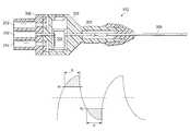
- FIG. 4is an illustration of an exemplary pressure wave form identifying a measured pressure characteristic and including thresholds and peaks in accordance with one aspect of the present invention.
- FIG. 5is an illustration of an exemplary model showing feedback control steps in accordance with one aspect of the present invention.
- FIG. 6is an illustration of a flow chart showing exemplary steps for determining adjustments to stored operating parameters in accordance with one aspect of the present invention.
- FIG. 7is an illustration of an exemplary model showing the feedback control steps in accordance with another aspect of the present invention.
- the present disclosureis directed to a surgical system including a vitrectomy cutter for performing ophthalmic surgeries.
- the surgical systemis arranged and configured to use feedback control to detect and to compensate for deviations in operation due to inconsistencies arising from individual component tolerances or degradation.
- the feedback controlcan reduce the overall sensitivity of the system to individual component tolerances, variations, and overall deviations from desired characteristics. This approach can potentially accommodate a wider range of critical component tolerances, and can compensate for changes or variations resulting from component ageing or adverse environmental effects, such as temperature.
- the systemis arranged and configured to identify when operating parameters are outside of acceptable ranges and to use control laws to modify the operating parameters to place them back within acceptable ranges. This results in more consistent cutter operation and consequently more predictable surgeries, while potentially extending the life of particular components, resulting in lower expenses to the patient.
- FIG. 1illustrates a vitrectomy surgical machine, generally designated 100 , according to an exemplary embodiment.
- the machine 100includes a base housing 102 and an associated display screen 104 showing data relating to system operation and performance during a vitrectomy surgical procedure.
- the machineincludes a vitrectomy cutter system 110 that includes a vitrectomy cutter 112 and is configured to provide feedback control to compensate for variations in operation due to mechanical inconsistencies created by tolerances, component wear, or other factors.
- FIG. 2is a schematic of the vitrectomy cutter system 110 that provides feedback according to one exemplary embodiment.
- the cutter system 110includes the vitrectomy cutter 112 , a pneumatic pressure source 202 , an adjustable directional on-off pneumatic actuator 204 , pressure transducers 206 , 208 , a muffler 210 , and a controller 216 .
- the various componentsare in fluid communication with each other along lines representing flow paths or flow lines.
- the vitrectomy cutter 112is a pneumatically driven cutter having, as shown in FIG. 2 , a first port 212 and a second port 214 . It operates by receiving pneumatic pressure alternating through the first and second ports 212 , 214 .
- FIG. 3shows a cross-sectional illustration of an exemplary vitrectomy cutter, referenced by the numeral 112 .
- the cutter 112includes as its basic components an outer cutting tube 300 , an inner cutting tube 302 , and a reciprocating air driven piston 304 , all partially encased by a housing 306 .
- the housing 306includes an end piece 308 at the cutter proximal end with the first and second air supply ports 212 , 214 (also in FIG. 2 ) and one suction port 310 .
- the exemplary cutter 112operates by moving the inner cutting tube 302 past a tissue-receiving suction port (not shown) in the outer cutting tube 300 .
- the inner cutting tube 302 and the outer cutting tube 300cut tissue using a shearing action, similar to that of a scissors, as the inner tube reciprocates to open and close the tissue receiving port.
- a close fit between the tubesprevents vitreous material from being pulled into the space between the inner and outer cutting tubes when the inner cutting tube 302 opens the tissue-receiving suction port.
- the piston 304will move down, displacing the inner cutting tube 302 relative to the outer cutting tube 300 , thereby closing the tissue-receiving suction port of the outer cutting tube 300 .
- Thiscuts any vitreous material which may have been aspirated into the tissue-receiving suction port. Venting the pressure at the first port 212 and increasing the pressure at the second port 214 will move the piston up, opening the tissue-receiving suction port so that it can draw in new vitreous material to be cut.
- the operation of one exemplary cutteris described in greater detail in U.S. Pat. No. 5,176,628, incorporated herein by reference.
- exemplary cuttersinclude flexible diaphragms in place of the piston for opening and closing the tissue-receiving port.
- any cutter having reciprocating action driven by alternating pneumatic pressuremay be suitable for use with the system disclosed herein.
- the vitrectomy cutter 112is designed to provide about 5,000 cuts per minute, although both higher and lower cut rates are contemplated.
- the vitrectomy cutter system's on-off pneumatic actuator 204is a standard four-way on-off valve.
- the pneumatic actuatorhas a solenoid that operates to move the actuator to one of the two on-off positions depicted in the example of FIG. 2 .
- the pneumatic actuator 204is in a position to provide pneumatic pressure to the first port 212 , and to vent pneumatic pressure from the second port 214 . In this position, pneumatic pressure can pass from the pressure source 202 , through the on-off pneumatic actuator 204 , and to the first port 212 where the pneumatic pressure provides pneumatic power to the vitrectomy cutter.
- pneumatic pressure at the second port 214can pass through the on-off pneumatic actuator 204 to the muffler 210 where it is exhausted to the atmosphere.
- the on-off pneumatic actuator 204allows pneumatic pressure to pass from the pressure source 202 to the second port 214 where the pneumatic pressure provides pneumatic power to the vitrectomy cutter 112 .
- pneumatic pressure at the first port 212can vent through the on-off pneumatic actuator 204 to the muffler 210 where it is exhausted to the atmosphere.
- the on-off pneumatic actuatoris configured to receive operating signals from the controller 216 as further described below.
- pneumatic pressureis directed alternately from the source 202 to the first and second ports 212 , 214 to operate the vitrectomy cutter 112 .
- the on-off pneumatic actuator 204alternates between its two positions very rapidly to alternatingly provide pneumatic pressure to the first and second ports 212 , 214 .
- pneumatic actuator 204Although shown with a single pneumatic actuator 204 , other embodiments include two pneumatic actuators, one associated with each of the two ports 212 , 214 . These embodiments operate similar to the manner described, with the actuators being are configured to independently receive operating signals from the controller 216 .
- the pressure transducers 206 , 208operate to detect pneumatic pressure levels at the respective first and second ports 212 , 214 . These pressure transducers 206 , 208 may be standard pressure transducers capable of detecting compressed pneumatic pressure levels and communicating data representing the detected pressure levels to the controller 216 .
- the controller 216is, for example, a PID controller, an integrated circuit configured to perform logic functions, or a microprocessor that performs logic functions. It may include a memory and a processor that may execute programs stored in the memory. In some embodiments, the memory stores minimum threshold pressures, particular desired time lengths, and desired peak pressures, among other parameters, for particular duty cycles or cut rates of the vitrectomy cutter 112 .
- the controller 216is configured to provide a timing function that tracks the amount of time that measured pressures are above stored threshold pressures.
- the controller 216is in communication with the on-off pneumatic actuator 204 and the pressure transducers 206 , 208 . As described below, the controller 216 is configured to control operation of the pneumatic actuator 204 based on feedback received from the pressure transducers 206 , 208 .
- FIG. 4is an exemplary wave form 400 representing a pressure wave at a particular duty cycle.
- the pressure above the medianrepresents pressure detected by the first pressure transducer 206 at the first port 212 and the pressure below the median represents the pressure detected by the second pressure transducer 208 at the second port 214 .
- the wave form 400includes minimum pressure thresholds (P 0 , P 1 ) that are input and stored in the controller 216 .
- These minimum pressure thresholds (P 0 , P 1 )are threshold pressure values that must be met or exceeded in order to operate the vitrectomy cutter to fully open or close the tissue receiving port.
- the actual pressures (p 0 , p 1 ) at the pneumatic portsmust 212 , 214 exceed the minimum pressure thresholds (P 0 , P 1 ) for a desired length of time (T 0 , T 1 ) corresponding to the desired cut rate or duty cycle. This is described below with reference to the exemplary vitrectomy cutter 112 in FIG. 3 .
- the pressure transducer 206measures the actual pressure (p 1 ) at the first port 212 .
- the actual pressure (p 1 )must meet or exceed the minimum threshold pressure (P 1 ) shown in FIG. 4 . If the minimum threshold pressure (P 1 ) is not met or exceeded, the pneumatic piston 304 may not displace far enough to fully close the tissue receiving port in the outer cutting tube 300 in the cutter in FIG. 3 .
- the systemcontrols the duty cycle. As the time at or exceeding the threshold pressure (P 1 ) changes, so does the cut rate or duty cycle.
- the pressure transducer 208measures the actual pressure (p 0 ) at the second port 214 .
- the actual pressure (p 0 )must meet or exceed the minimum threshold pressure (P 0 ). Consequently, failure to meet the minimum threshold pressure (P 0 ) may result in only a partially open tissue receiving port in the cutter in FIG. 3 .
- the actual pressure (p 0 )should meet or exceed the minimum threshold pressure (P 0 ) for a desired length of time (T 0 ) corresponding to the desired cut rate or duty cycle.
- the controller 216is configured to compensate for component tolerances and variations by measuring and tracking the actual time (t 0 , t 1 ) that the measured actual pressures (p 0 , p 1 ) are above the respective minimum pressure thresholds (P 0 , P 1 ). By comparing the actual time (t 0 , t 1 ) to the desired time (T 0 , T 1 ), the controller 216 may calculate a difference or margin usable to modify the control signals sent to the on-off pneumatic actuator 204 to adjust the cutter's duty cycle. In can do this based on control laws that determine whether adjustments should be made to signals being sent to the on-off pneumatic actuator 204 . This becomes more clear with reference to an exemplary method below of generating and using feedback control for the pneumatic on-off pneumatic actuator 204 .
- FIG. 5shows an exemplary control loop 500 for generating and using feedback control to reduce errors due to component variation, such as may occur with, for example, tolerance build up or wear.
- An exemplary method of feedback controlwill be described with reference to the control loop 500 .
- the system 110receives an input from a health care provider setting a particular cut rate and/or duty cycle. This may be done using an input device on the machine 100 , may be input by controlling an input on the vitrectomy cutter 112 .
- Input examplesmay include squeezing the cutter handle to adjust the duty cycle, inputting via selection on a screen using a keyboard, mouse, knobs, or other known input device.
- the settingis prestored in the system using default or pre-programmed values.
- the systemthen initializes and operates at that particular setting and controls the on-off pneumatic actuator 204 to pneumatically actuate the cutter 112 .
- the controller 216stores data representing minimum pressure thresholds (P 0 , P 1 ) that must be met or exceeded at each port to fully open and close the tissue receiving port on the vitrectomy cutter.
- the feedback controlbegins at the differential pressure sensor 502 .
- the differential pressure sensor 502represents the first and second pressure transducers 206 , 208 .
- other pressure sensor arrangementsare used, including in some embodiments, only a single pressure sensor.
- the feedback controlbegins when the differential pressure sensor 502 detects the actual pneumatic pressures (p 0 , p 1 ) at the first and second ports 212 , 214 .
- the differential pressure sensor 502may be physically associated with pneumatic flow lines on the machine 100 , may be on the cutter 112 itself, or elsewhere located, so long as it is able to detect the pressure representative of or indicative of pressure at the first and second ports 212 , 214 .
- the differential pressure sensor 502outputs data indicative of the actual pressures (p 0 , p 1 ) in the first and second ports 212 , 214 as an analog signal.
- an analog to digital converter (ADC) 504converts the analog signal to digital form.
- the ADC 504may be physically associated with the differential pressure sensor 502 , may be a part of the controller 216 , or may be disposed in between.
- the ADC 504is also configured in a manner that tracks the actual length of time (t 0 , t 1 ) that the measured pressures (p 0 , p 1 ) meet or exceed pre-stored minimum pressure thresholds (P 0 , P 1 ). These minimum pressure thresholds (P 0 , P 1 ) represent pressures required to fully open or fully close the tissue-receiving port on the cutter. Therefore, the actual length of time (t 0 , t 1 ) is indicative of the actual length of time that the tissue receiving port is fully open or fully closed. The actual length of time (t 0 , t 1 ) may be for a single cutting cycle, or may be averaged over a plurality of cutting cycles. The ADC 504 then outputs the actual length of time (t 0 , t 1 ). In some embodiments, the controller 216 tracks the time instead of the ADC 504 .
- the digital signalis then filtered by a digital filter 506 in a manner known in the art to provide meaningful data for treatment by a summing module 508 executable in the controller 216 .
- the summing module 508is configured to detect an error or margin (e 0 , e 1 ) in lengths of time for both the time the tissue-receiving port is fully open and the time the tissue-receiving port is fully closed. This is based on the actual length of time (t 0 , t 1 ) compared to the desired length of time (T 0 , T 1 ) for the selected cutting rate and/or duty cycle. These may be averaged over a number of cycles.
- One exemplary process for determining the margins (e 0 , e 1 )is set forth below.
- the margin e 0represents the margin in one actuator position.
- the actuator positionmay be a position that provides pneumatic pressure to open the tissue-receiving port on the vitrectomy cutter 112 .
- the margin e 1represents the margin in the opposing actuator position.
- the opposing actuator positionmay be a position that provides pneumatic pressure to close the tissue-receiving port on the vitrectomy cutter 112 .
- the marginsare based on averages taken over a plurality of cycles.
- the controller 216uses control laws 510 to determine whether changes should be made to the duty cycle data used to control the pneumatic actuator 204 .
- One exemplary control law, referenced herein by the numeral 600is explained with reference to FIG. 6 .
- the control law 600 in FIG. 6starts at a step 602 .
- the control lawqueries whether the margin e 0 and the margin e 1 are both equal to or greater than zero. If yes, then the system is operating correctly because the actual length of time (t 0 , t 1 ) that the actual pressure (p 0 , p 1 ) is at or above the minimum pressure threshold (P 0 , P 1 ) is equal to or greater than the desired length of time (T 0 , T 1 ). Accordingly, the duty cycle and cut rate need not change and the query ends at step 606 . Alternatively, in some embodiments, if necessary, the system may still use the asymmetry E as the loop error to increase or decrease the duty cycle using the controller 216 to provide more exact operation.
- the control lawqueries whether e 0 is greater than or equal to zero and e 1 is less than zero at step 608 . If yes, then the system corrects the duty cycle at step 610 using E as the loop error to increase the amount of time that pneumatic pressure is directed to port 214 by controlling the pneumatic actuator 204 . Correcting the duty cycle may include adjusting or updating stored operating data used to generate timing signals for a particular duty cycle. The control law then ends at step 606 .
- step 608the system queries whether e 0 is less than zero and e 1 is equal to or greater than zero at a step 612 . If yes, then the system corrects the duty cycle at step 614 using E as the loop error to increase the amount of time that pneumatic pressure is directed to port 212 by controlling the pneumatic actuator 204 . The control law then ends at step 606 .
- Steps 608 and 610determine whether the amount of time the actuator is opened should be increased or should be decreased.
- the asymmetry Erepresents the amount of the increase or decrease.
- the calculated margins (e 0 , e 1 )represent the amount of the increase or decrease.
- both e 0 and e 1are less than zero, as indicated at step 616 . Therefore, the system enters a fault condition because a duty cycle correction is insufficient to correct the condition.
- a potential cause of such a condition at step 616is a low source pressure, resulting in an amplitude insufficient to meet the minimum threshold pressures to fully open or to fully close the tissue receiving port in the cutter 112 .
- Another potential cause of such a conditionis that the cut rate is higher than can be sustained by the system at the current operating parameters.
- the systemmay notify the health care provider with an audible, visual, or tactile signal that the system is not in operating condition.
- the system 110may make efforts to control the pneumatic pressure source 202 to increase the source pressure. In this embodiment, if the source pressure is increased sufficiently, then the system may return to the start of the control law. If increasing the source pressure is not possible, then the fault condition may be triggered.
- the systemmay prompt the user with an indication that the cut rate may need to be decreased to achieve the desired duty cycle. Any change to cut rate may be done either manually at the user's instruction or automatically.
- the control lawends at step 606 .
- the systemoutputs the correction as (u 0 , u 1 ).
- This correction (u 0 , u 1 )is then used to update the stored duty cycle control data 512 to more closely align the desired length of time (T 0 , T 1 ) with the actual length of time (t 0 , t 1 ) that the actual pressure (p 0 , p 1 ) is above the minimum threshold pressure (P 0 , P 1 ). In some examples, this is done by updating a table stored in the controller memory that tracks and associates the desired times with the desired cutting rates or duty cycles.
- the systemuses the updated duty cycle data to generate a control signal for controlling the pneumatic actuator 204 .
- the pneumatic actuatorsince the pneumatic actuator may vary by type and number used, the pneumatic actuator is represented by the pneumatics manifold 516 . The method may then repeat to continuously detect and correct deviations from desired values that may occur.
- the system 110provides feedback based only upon detected pressure without monitoring the actual time spent above the minimum pressure thresholds.
- FIG. 7shows an example of operation of this alternative control loop. In many respects, the alternative embodiment in FIG. 7 is similar to that described above in FIG. 5 . Only differences are described in detail.
- the control loop 700operates in manner similar to that described above, where the system receives an input from a health care provider setting a particular cut rate and/or duty cycle. Based on the inputs or on pre-stored data, the controller 216 stores data representing peak pressures (PK 0 , PK 1 ) that must be met at each port to fully open and close the tissue receiving port on the vitrectomy cutter for the length of time corresponding to the desired duty cycle or cut rate. The peak pressures represent the maximum pressures shown at the tips of the wave forms.
- the feedback controlbegins at the differential pressure sensor 702 .
- the differential pressure sensor 702outputs data indicative of the actual pressures (pk 0 , pk 1 ) in the first and second ports 212 , 214 as an analog signal.
- An ADC 704converts the analog signal to digital form.
- the ADCidentifies the actual detected peak pressures (pk 0 , pk 1 ). These are the maximum pressures identified by the pressure transducers 206 , 208 for their respective port 212 , 214 .
- the digital signalis then filtered by a digital filter 706 in a manner known in the art to provide meaningful data for treatment by a summing module 708 executable in the controller 216 .
- the margins e 0 , e 1each represent the margin in different actuator positions. These actuator positions may be those that provide pneumatic pressure to fully open or fully close the tissue-receiving port on the vitrectomy cutter 112 .
- the controller 216uses control laws 710 to determine whether changes should be made to the duty cycle data used to control the pneumatic actuator 204 .
- the control lawis the same as the control law described with reference to FIG. 6 .
- the systemAfter using the control law 710 to determine whether the duty cycle needs correction, if necessary, the system outputs the correction as (u 0 , u 1 ). This correction (u 0 , u 1 ) is then used to update the duty cycle 712 to more closely align the desired peak pressure (PK 0 , PK 1 ) with the actual pressure (pk 0 , pk 1 ).
- the systemuses the updated duty cycle data to generate a control signal for controlling the pneumatics manifold 716 with the on-off pneumatic actuator 204 .
- the methodmay then repeat to continuously detect and correct deviations from desired values that may occur.
- This feedback controlcan be used to reduce the overall sensitivity of the system to individual component tolerances, variations, and overall deviations from desired characteristics. This approach does not require factory calibration, can accommodate a wider range of critical component tolerances, and continues to compensate for changes as a result of component aging, or adverse environmental effects, such as temperature.
Landscapes
- Health & Medical Sciences (AREA)
- Surgery (AREA)
- Life Sciences & Earth Sciences (AREA)
- Engineering & Computer Science (AREA)
- Veterinary Medicine (AREA)
- Biomedical Technology (AREA)
- Heart & Thoracic Surgery (AREA)
- Nuclear Medicine, Radiotherapy & Molecular Imaging (AREA)
- Animal Behavior & Ethology (AREA)
- General Health & Medical Sciences (AREA)
- Public Health (AREA)
- Ophthalmology & Optometry (AREA)
- Medical Informatics (AREA)
- Molecular Biology (AREA)
- Vascular Medicine (AREA)
- Surgical Instruments (AREA)
- Fluid-Pressure Circuits (AREA)
Abstract
Description
e0=t0−T0=(actual length of time)−(desired length of time); and
e1=t1−T1=(actual length of time)−(desired length of time).
E=e1−e0.
e0=pk0−PK0=(actual peak pressure)−(desired peak pressure); and
e1=pk1−PK1=(actual peak pressure)−(desired peak pressure).
E=e1−e0.
Claims (19)
Priority Applications (8)
| Application Number | Priority Date | Filing Date | Title |
|---|---|---|---|
| US12/788,609US8821524B2 (en) | 2010-05-27 | 2010-05-27 | Feedback control of on/off pneumatic actuators |
| CA2798251ACA2798251C (en) | 2010-05-27 | 2011-05-02 | Feedback control of on/off pneumatic actuators |
| ES11787078.2TES2567187T3 (en) | 2010-05-27 | 2011-05-02 | Feedback control of pneumatic actuators on / off |
| CN201180026137.9ACN102917653B (en) | 2010-05-27 | 2011-05-02 | Feedback Control of On-Off Pneumatic Actuators |
| PCT/US2011/034720WO2011149621A1 (en) | 2010-05-27 | 2011-05-02 | Feedback control of on/off pneumatic actuators |
| AU2011258776AAU2011258776B2 (en) | 2010-05-27 | 2011-05-02 | Feedback control of on/off pneumatic actuators |
| JP2013512629AJP5814352B2 (en) | 2010-05-27 | 2011-05-02 | Feedback control of on-off type pneumatic actuator |
| EP11787078.2AEP2575633B1 (en) | 2010-05-27 | 2011-05-02 | Feedback control of on/off pneumatic actuators |
Applications Claiming Priority (1)
| Application Number | Priority Date | Filing Date | Title |
|---|---|---|---|
| US12/788,609US8821524B2 (en) | 2010-05-27 | 2010-05-27 | Feedback control of on/off pneumatic actuators |
Publications (2)
| Publication Number | Publication Date |
|---|---|
| US20110295293A1 US20110295293A1 (en) | 2011-12-01 |
| US8821524B2true US8821524B2 (en) | 2014-09-02 |
Family
ID=45004272
Family Applications (1)
| Application Number | Title | Priority Date | Filing Date |
|---|---|---|---|
| US12/788,609Active2030-09-23US8821524B2 (en) | 2010-05-27 | 2010-05-27 | Feedback control of on/off pneumatic actuators |
Country Status (8)
| Country | Link |
|---|---|
| US (1) | US8821524B2 (en) |
| EP (1) | EP2575633B1 (en) |
| JP (1) | JP5814352B2 (en) |
| CN (1) | CN102917653B (en) |
| AU (1) | AU2011258776B2 (en) |
| CA (1) | CA2798251C (en) |
| ES (1) | ES2567187T3 (en) |
| WO (1) | WO2011149621A1 (en) |
Cited By (5)
| Publication number | Priority date | Publication date | Assignee | Title |
|---|---|---|---|---|
| US9615969B2 (en) | 2012-12-18 | 2017-04-11 | Novartis Ag | Multi-port vitrectomy probe with dual cutting edges |
| US9693898B2 (en) | 2014-11-19 | 2017-07-04 | Novartis Ag | Double-acting vitreous probe with contoured port |
| US10893978B2 (en) | 2017-12-14 | 2021-01-19 | Alcon Inc. | Vitreous cutter pneumatic driver |
| US11540942B2 (en) | 2018-07-26 | 2023-01-03 | Alcon Inc. | Redundant pneumatic circuit for reliability enhancement of vitrectomy instruments |
| US11642243B2 (en) | 2018-12-10 | 2023-05-09 | Alcon Inc. | Methods of solenoid valve control optimization |
Families Citing this family (20)
| Publication number | Priority date | Publication date | Assignee | Title |
|---|---|---|---|---|
| US8460324B2 (en) | 2008-04-15 | 2013-06-11 | Abbott Medical Optics Inc. | High speed pneumatic vitrectomy control |
| JP5770731B2 (en)* | 2009-08-31 | 2015-08-26 | アルコン リサーチ, リミテッド | Control of pneumatic output by drive valve duty |
| ES2442368T3 (en)* | 2009-12-10 | 2014-02-11 | Alcon Research, Ltd. | Systems and procedures for dynamic pneumatic valve actuator |
| US8821524B2 (en) | 2010-05-27 | 2014-09-02 | Alcon Research, Ltd. | Feedback control of on/off pneumatic actuators |
| US8888802B2 (en)* | 2010-12-21 | 2014-11-18 | Alcon Research, Ltd. | Vitrectomy probe with adjustable cutter port size |
| US9101441B2 (en) | 2010-12-21 | 2015-08-11 | Alcon Research, Ltd. | Vitrectomy probe with adjustable cutter port size |
| US8808318B2 (en) | 2011-02-28 | 2014-08-19 | Alcon Research, Ltd. | Surgical probe with increased fluid flow |
| US8496681B2 (en) | 2011-06-06 | 2013-07-30 | Synergetics, Inc. | Systems and methods for vitrectomy |
| US9060841B2 (en) | 2011-08-31 | 2015-06-23 | Alcon Research, Ltd. | Enhanced flow vitrectomy probe |
| US9517161B2 (en) | 2011-12-20 | 2016-12-13 | Alcon Research, Ltd. | Vitrectomy probe with adjustable cutter port size |
| NL2009424C2 (en) | 2012-09-06 | 2014-03-10 | D O R C Dutch Ophthalmic Res Ct International B V | Irrigation/aspiration system, cartridge, pump unit, surgical machine, method for controlling. |
| US9271867B2 (en)* | 2012-12-17 | 2016-03-01 | Abbott Medical Optics Inc. | Vitrectomy surgical apparatus with regulating of material processed |
| US9486358B2 (en) | 2012-12-17 | 2016-11-08 | Abbott Medical Optics Inc. | Vitrectomy surgical apparatus |
| US9498376B2 (en)* | 2012-12-17 | 2016-11-22 | Abbott Medical Optics Inc. | Vitrectomy surgical apparatus with cut timing based on pressures encountered |
| US9757273B2 (en) | 2013-12-20 | 2017-09-12 | Novartis Ag | Tissue-sensing vitrectomy surgical systems and methods |
| WO2015164459A1 (en)* | 2014-04-23 | 2015-10-29 | Abbott Medical Optics Inc. | Vitrectomy surgical apparatus employing multisensor pressure feedback |
| DE102017208584A1 (en)* | 2017-05-22 | 2018-11-22 | Geuder Ag | Apparatus for providing compressed air pulses to an ophthalmological instrument and a control method for such an apparatus |
| WO2019126095A1 (en) | 2017-12-21 | 2019-06-27 | Swagelok Company | Systems and methods for control and monitoring of actuated valves |
| NL2022011B1 (en)* | 2018-11-16 | 2020-05-26 | Crea Ip B V | Vitrectome actuator |
| CN116301086B (en)* | 2023-05-16 | 2023-09-05 | 图湃(北京)医疗科技有限公司 | Vitrectomy machine, monitoring method and device for vitrectomy machine |
Citations (172)
| Publication number | Priority date | Publication date | Assignee | Title |
|---|---|---|---|---|
| US812162A (en) | 1905-12-18 | 1906-02-06 | Thomas Bemis | Pneumatic tube for store service. |
| US2016746A (en) | 1933-08-25 | 1935-10-08 | Thomas H Ireland | Fluid heater |
| US2707389A (en) | 1949-06-30 | 1955-05-03 | Etavex S A | Pneumatic differential apparatus |
| GB792397A (en) | 1956-05-09 | 1958-03-26 | Pneumatic Components Ltd | Improvements in or relating to tyre inflation hose equipment |
| US3084674A (en) | 1961-07-20 | 1963-04-09 | Ingersoll Rand Co | Pneumatic system for multiple nut runner |
| US3477665A (en) | 1966-09-16 | 1969-11-11 | Sud Aviat Soc Nationale De Con | Vibration attenuating method and electrohydraulic attenuator for rotarywing aircraft |
| GB1189493A (en) | 1966-05-23 | 1970-04-29 | Foxboro Co | Method and Apparatus for Adaptive Control |
| GB1213723A (en) | 1967-02-24 | 1970-11-25 | Air Reduction | Gas mixture proportioner |
| US3646727A (en) | 1969-06-02 | 1972-03-07 | Erich A Wachsmuth | Automatic compressor drain system |
| US3703139A (en) | 1969-11-20 | 1972-11-21 | Westland Aircraft Ltd | Pressure control systems |
| GB1323788A (en) | 1970-12-10 | 1973-07-18 | Aquitaine Petrole | Hydraulically controlled systems for modulating the fluid flow at the bottom of a drilling well |
| US3815604A (en) | 1972-06-19 | 1974-06-11 | Malley C O | Apparatus for intraocular surgery |
| US3854382A (en) | 1973-06-20 | 1974-12-17 | Sperry Rand Ltd | Hydraulic actuator controls |
| US3867934A (en) | 1973-05-04 | 1975-02-25 | Veriflo Corp | Pressure monitor for a lung ventilator |
| GB1417299A (en) | 1973-09-18 | 1975-12-10 | Gulde Regelarmatuhren Kg | Method and apparatus for safe-guarding pipe-lines against inadmissibly high internal pressure by a control valve with a pneumatic drive |
| US4011869A (en) | 1975-08-01 | 1977-03-15 | David Kopf Instruments | Tubular cutting instrument |
| US4077567A (en) | 1976-06-18 | 1978-03-07 | Universal Pneumatic Controls, Inc. | Pneumatic temperature reset differential pressure controller |
| US4086804A (en) | 1976-10-26 | 1978-05-02 | Sperry Rand Corporation | Precision pneumatic pressure supply system |
| US4164167A (en) | 1975-11-21 | 1979-08-14 | Ishikawajima-Harima Jukogyo Kabushiki Kaisha | Hydraulic servomechanism |
| US4168707A (en) | 1977-06-13 | 1979-09-25 | Douvas Nicholas G | Control apparatus for microsurgical instruments |
| GB2016746A (en) | 1978-03-16 | 1979-09-26 | Knorr Bremse Gmbh | Fluid pressure control system |
| US4255789A (en) | 1978-02-27 | 1981-03-10 | The Bendix Corporation | Microprocessor-based electronic engine control system |
| US4323064A (en) | 1976-10-26 | 1982-04-06 | Puritan-Bennett Corporation | Volume ventilator |
| US4331130A (en) | 1980-06-27 | 1982-05-25 | Lewicky Andrew O | Securing device to the cornea to prevent anterior chamber prolapse |
| US4335867A (en) | 1977-10-06 | 1982-06-22 | Bihlmaier John A | Pneumatic-hydraulic actuator system |
| US4344144A (en) | 1979-05-02 | 1982-08-10 | Intertechnique | Apparatus for creating gas flow cycles |
| US4368734A (en) | 1978-01-27 | 1983-01-18 | Surgical Design Corp. | Surgical instrument |
| US4476532A (en) | 1978-12-18 | 1984-10-09 | Nippondenso Co., Ltd. | Method and apparatus for controlling the duty cycle of an off-on type valve by monitoring the history of the state of the valve |
| GB2140871A (en) | 1983-06-03 | 1984-12-05 | Bowthorpe Hellermann Ltd | Piston and cylinder actuator control |
| US4590935A (en) | 1981-11-02 | 1986-05-27 | Optikon Oftalmologia, S.P.A. | Control system for intraocular surgical device |
| US4622503A (en) | 1985-09-26 | 1986-11-11 | Medical Instrument Development Laboratories, Inc. | Variable pneumatic output means for use with ophthalmic micro-surgical instruments |
| US4650460A (en) | 1984-06-28 | 1987-03-17 | Jaime Roizenblatt | Pneumatic module for intraocular microsurgery |
| US4650462A (en) | 1985-07-29 | 1987-03-17 | Minnesota Mining And Manufacturing Company | Irrigation system |
| US4678459A (en) | 1984-07-23 | 1987-07-07 | E-Z-Em, Inc. | Irrigating, cutting and aspirating system for percutaneous surgery |
| US4679583A (en) | 1984-04-19 | 1987-07-14 | Robertshaw Controls Company | Pneumatic control system, control means therefor and method of making the same |
| US4696298A (en) | 1985-11-19 | 1987-09-29 | Storz Instrument Company | Vitrectomy cutting mechanism |
| US4706687A (en) | 1985-02-28 | 1987-11-17 | Alcon Instrumentation, Inc. | Linear suction control system |
| US4757814A (en) | 1985-02-28 | 1988-07-19 | Alcon Laboratories, Inc. | Proportional control for pneumatic cutting device |
| US4770654A (en) | 1985-09-26 | 1988-09-13 | Alcon Laboratories Inc. | Multimedia apparatus for driving powered surgical instruments |
| GB2203195A (en) | 1987-03-19 | 1988-10-12 | Festo Kg | Circuit for operating a fluid-pressure driven piston |
| US4790816A (en) | 1985-09-26 | 1988-12-13 | Allon Laboratories, Inc. | Surgical cassette proximity sensing and latching apparatus |
| US4810242A (en) | 1985-09-26 | 1989-03-07 | Alcon Laboratories Inc. | Surgical cassette proximity sensing and latching apparatus |
| US4840111A (en) | 1986-01-31 | 1989-06-20 | Moog Inc. | Energy-conserving regenerative-flow valves for hydraulic servomotors |
| US4933843A (en) | 1986-11-06 | 1990-06-12 | Storz Instrument Company | Control system for ophthalmic surgical instruments |
| US4985027A (en) | 1990-02-26 | 1991-01-15 | Dressel Thomas D | Soft tissue aspiration device and method |
| DE3925405A1 (en) | 1989-08-01 | 1991-02-07 | Vdo Schindling | Pressure control unit esp. for vehicle windscreen wiper - has solenoid controlled relief valve to control pressure in load stage |
| US5019035A (en) | 1989-06-07 | 1991-05-28 | Alcon Surgical, Inc. | Cutting assembly for surgical cutting instrument |
| US5020825A (en) | 1987-03-18 | 1991-06-04 | Monroe Auto Equipment Company | Method and apparatus for absorbing mechanical shock |
| US5020315A (en) | 1989-08-08 | 1991-06-04 | United Technologies Corporation | Multiple function fuel valve and system |
| US5024654A (en) | 1989-10-02 | 1991-06-18 | Alcon Surgical, Inc. | Insulated infusion and aspiration probe |
| US5047008A (en) | 1989-10-27 | 1991-09-10 | Storz Instrument Company | Vitrectomy probe |
| WO1992002866A1 (en) | 1990-08-03 | 1992-02-20 | E.I. Du Pont De Nemours And Company | Computer neural network process measurement and control system and method |
| US5092178A (en) | 1989-04-28 | 1992-03-03 | Pneumo Abex Corporation | Differential pressure sensor mechanisms |
| US5094260A (en) | 1990-10-26 | 1992-03-10 | Alcon Surgical, Inc. | Proportional valve and pressure control system |
| US5106364A (en) | 1989-07-07 | 1992-04-21 | Kabushiki Kaisha Topcon | Surgical cutter |
| US5138564A (en) | 1990-07-31 | 1992-08-11 | Xerox Corporation | Automatic encoder calibration |
| US5154207A (en) | 1991-08-02 | 1992-10-13 | Mosier Industries, Inc. | Pressure control valve and transducer package |
| US5176628A (en) | 1989-10-27 | 1993-01-05 | Alcon Surgical, Inc. | Vitreous cutter |
| US5217465A (en) | 1992-02-28 | 1993-06-08 | Alcon Surgical, Inc. | Flexible and steerable aspiration tip for microsurgery |
| US5239861A (en) | 1988-12-23 | 1993-08-31 | Kabushiki Kaisha Komatsu Seisakusho | Device for indicating contamination degree of hydraulic circuit and method of judging the contamination degree |
| WO1993018445A1 (en) | 1992-03-11 | 1993-09-16 | Emhart Glass Machinery Investments Inc, | Control system for glassware forming machine |
| DE4232586A1 (en) | 1992-09-23 | 1994-03-24 | Mannesmann Ag | Switching valve with regulation of output pressure - has inlet valve stage that closes when output pressure exceeds reference with vent valve stage opening to control pressure |
| US5314295A (en) | 1992-02-07 | 1994-05-24 | Valmet Paper Machinery, Inc. | Roll stop and operating method of the same |
| EP0626628A1 (en) | 1993-05-11 | 1994-11-30 | MANNESMANN REXROTH GmbH | Control system for a hydraulic drive |
| US5380280A (en) | 1993-11-12 | 1995-01-10 | Peterson; Erik W. | Aspiration system having pressure-controlled and flow-controlled modes |
| US5403276A (en) | 1993-02-16 | 1995-04-04 | Danek Medical, Inc. | Apparatus for minimally invasive tissue removal |
| US5417246A (en) | 1989-10-27 | 1995-05-23 | American Cyanamid Company | Pneumatic controls for ophthalmic surgical system |
| US5437241A (en) | 1994-06-08 | 1995-08-01 | Pall Corporation | Differential pressure indicator |
| US5445773A (en) | 1993-09-08 | 1995-08-29 | Nissei Plastic Industrial Co., Ltd. | Method for detecting abnormality in hydraulic system of molding machine and apparatus therefor |
| US5457625A (en) | 1994-04-13 | 1995-10-10 | The M. W. Kellogg Company | Maximizing process production rates using permanent constraints |
| WO1995031141A1 (en) | 1994-05-12 | 1995-11-23 | Syntec, Inc. | Pneumatic vitrectomy for retinal attachment |
| US5550685A (en) | 1993-10-22 | 1996-08-27 | Syquest Technology, Inc. | Applying an adaptive feed-forward algorithm as a frequency selective filter in a closed loop disk drive servo system in order to compensate for periodic perturbations which otherwise appear in the servo system position error signal |
| US5571248A (en) | 1995-03-10 | 1996-11-05 | General Motors Corporation | Pressure regulator |
| US5580347A (en) | 1991-07-31 | 1996-12-03 | Mentor Ophthalmics, Inc. | Controlling operation of handpieces during ophthalmic surgery |
| US5587536A (en) | 1995-08-17 | 1996-12-24 | Rasmussen; John | Differential pressure sensing device for pneumatic cylinders |
| US5630827A (en) | 1995-06-19 | 1997-05-20 | Dutch Ophthalmic Research Center International Bv | Vitreous removing apparatus |
| US5674194A (en) | 1995-10-25 | 1997-10-07 | Alcon Laboratories Inc. | Process control system |
| EP0673475B1 (en) | 1992-12-11 | 1998-06-03 | Danfoss A/S | Hydraulic system |
| WO1998025556A1 (en) | 1996-12-11 | 1998-06-18 | Chiron Vision Corporation | Remote control for ophthalmic surgical control console |
| US5791142A (en) | 1997-03-27 | 1998-08-11 | Husco International, Inc. | Hydraulic control valve system with split pressure compensator |
| US5808396A (en) | 1996-12-18 | 1998-09-15 | Alcon Laboratories, Inc. | System and method for tuning and controlling an ultrasonic handpiece |
| US5810765A (en) | 1994-06-30 | 1998-09-22 | Nidek Company, Ltd. | Irrigation/aspiration apparatus |
| EP0874163A2 (en) | 1997-04-23 | 1998-10-28 | Rudolf Westerberg AB | A double two-channel drive system for a pressurized fluid flow |
| US5829335A (en) | 1993-05-11 | 1998-11-03 | Mannesmann Rexroth Gmbh | Control for hydraulic drive or actuator |
| US5846257A (en) | 1997-08-15 | 1998-12-08 | Nexus Medical System, Inc. Llc | Pressure sensor for a surgical system |
| EP0884667A1 (en) | 1997-06-09 | 1998-12-16 | SMC Kabushiki Kaisha | Automatic pneumatic pressure control apparatus and method of controlling same |
| DE19821420C1 (en) | 1998-05-13 | 1999-10-21 | Haldex Bremsen Gmbh & Co Kg | Pressurized air device for automobile pneumatic circuits |
| US5989262A (en) | 1996-04-15 | 1999-11-23 | Josephberg; Robert Gary | Sutureless pars plana vitrectomy tool |
| US5993409A (en) | 1996-11-27 | 1999-11-30 | Surgin Surgical Instrumentation, Inc. | Needle for surgical use |
| US6155233A (en) | 1999-09-07 | 2000-12-05 | Fasco Controls Corp. | Combination pressure sensor and regulator for direct injection diesel engine fuel system |
| US6162187A (en) | 1999-08-02 | 2000-12-19 | Ethicon Endo-Surgery, Inc. | Fluid collection apparatus for a surgical device |
| WO2000078371A1 (en) | 1999-06-22 | 2000-12-28 | Scieran Technologies, Inc. | An apparatus and method for performing ophthalmic procedures |
| WO2001030281A1 (en) | 1999-10-22 | 2001-05-03 | Dutch Ophthalmic Research Center B.V. | Surgical pneumatic cutter |
| WO2001064120A1 (en) | 2000-03-01 | 2001-09-07 | Thermal Ablation Technologies Canada Inc. | Device for thermal ablation of a cavity |
| US6425883B1 (en) | 1998-05-08 | 2002-07-30 | Circuit Tree Medical, Inc. | Method and apparatus for controlling vacuum as a function of ultrasonic power in an ophthalmic phaco aspirator |
| US20020117214A1 (en) | 2001-02-28 | 2002-08-29 | Tucker Jeffrey C. | Fluid flow control system, fluid delivery and control system for a fluid delivery line, and method for controlling pressure oscillations within fluid of a fluid delivery line |
| US6450966B1 (en) | 2000-05-03 | 2002-09-17 | Datex-Ohmeda, Inc. | Method for non-invasive blood pressure cuff identification using deflation pressure measurements |
| US6485436B1 (en) | 2000-08-10 | 2002-11-26 | Csaba Truckai | Pressure-assisted biopsy needle apparatus and technique |
| US6514268B2 (en)* | 1999-08-30 | 2003-02-04 | Alcon Universal Ltd. | Method of operating microsurgical instruments |
| US20030042182A1 (en) | 2000-11-22 | 2003-03-06 | Pti Technologies, Inc. | Prognostic health monitoring of fluidic systems using MEMS technology |
| US6575990B1 (en) | 1999-10-21 | 2003-06-10 | Medical Instrument Development Laboratories, Inc. | High speed vitreous cutting system |
| US6575264B2 (en) | 1999-01-29 | 2003-06-10 | Dana Corporation | Precision electro-hydraulic actuator positioning system |
| US20030208305A1 (en) | 2002-05-03 | 2003-11-06 | Junk Kenneth W. | Method and apparatus for performing diagnostics in a control loop of a control valve |
| GB2389423A (en) | 2002-06-06 | 2003-12-10 | Detroit Diesel Corp | Oil filter monitor |
| EP1172586B1 (en) | 2000-07-12 | 2004-03-31 | Deere & Company | A method and apparatus for detecting a restricted or bypassed transmission oil filter |
| US6730106B2 (en) | 2000-10-20 | 2004-05-04 | Nidek Co., Ltd. | Vitreous surgical apparatus |
| DE10247869A1 (en) | 2002-10-14 | 2004-05-06 | Imi Norgren Gmbh | Pressure medium actuated working cylinder has differential pressure sensor on end part, connected to two pressure chambers via lines and with signal output dependent on chamber pressure difference |
| US20040154466A1 (en) | 2003-02-07 | 2004-08-12 | Gethmann Douglas P. | Control valve positioner mounting system |
| US6779541B2 (en) | 2001-10-12 | 2004-08-24 | Smc Kabushiki Kaisha | Fluid pressure regulator |
| US20040186484A1 (en) | 2003-01-29 | 2004-09-23 | Edwin Ryan | Small gauge surgical instrument with support device |
| US6848323B2 (en) | 2000-03-08 | 2005-02-01 | Rosemount Inc. | Hydraulic actuator piston measurement apparatus and method |
| US6851453B2 (en)* | 2000-02-29 | 2005-02-08 | Gen-Probe Incorporated | Fluid dispense verification system |
| US20050033309A1 (en) | 2003-01-29 | 2005-02-10 | Edwin Ryan | Small gauge surgical instrument with support device |
| US6892745B2 (en) | 2002-04-10 | 2005-05-17 | Honeywell International Inc. | Flow control valve with integral sensor and controller and related method |
| DE202005009670U1 (en) | 2005-06-17 | 2005-09-01 | Sieber, Dieter | Pneumatic drive muffler, has pressure sensor that produces warning signal and switches off pneumatic drive when impact pressure within cavity increased due to increased contamination of muffler reaches predetermined limit pressure |
| US20050245909A1 (en) | 2004-04-29 | 2005-11-03 | Mccary Brian D | Embedded data chip in a surgical handpiece |
| US6999853B2 (en) | 2002-05-03 | 2006-02-14 | Fisher Controls International Llc. | Methods and apparatus for operating and performing diagnostics in a control loop of a control valve |
| US20060129062A1 (en) | 2000-11-06 | 2006-06-15 | Nicoson Zachary R | Fluid control element for biopsy apparatus |
| US20060271082A1 (en) | 2005-05-31 | 2006-11-30 | Kirchhevel G Lamar | Calibrated surgical probe |
| EP1660244B1 (en) | 2003-09-05 | 2006-12-20 | Rainer Riehle | Sonic generator for generating sonic pulses that can propagate along pipelines of a water or gas supply system |
| US20070093793A1 (en) | 2005-10-11 | 2007-04-26 | Maurer Robert S Jr | Microsurgical probe |
| US7244240B2 (en) | 2000-09-29 | 2007-07-17 | Alcon, Inc. | Surgical cassette and consumables for combined opthalmic surgical procedure |
| US7254452B2 (en) | 2000-10-05 | 2007-08-07 | Ei Electronics Llc | Distributed input/output control systems and methods |
| US20070185512A1 (en) | 2006-02-06 | 2007-08-09 | Kirchhevel G L | Microsurgical instrument |
| US7263877B2 (en) | 2001-11-19 | 2007-09-04 | Luk Fahrzeug-Hydraulik Gmbh & Co. Kg | Determination of the piston stroke in a reciprocating piston machine |
| US20070219647A1 (en) | 2006-03-14 | 2007-09-20 | Asml Netherlands B.V. | System and method for moving a component through a setpoint profile, lithographic apparatus and device manufacturing method |
| US7283321B1 (en) | 2004-10-08 | 2007-10-16 | Maxtor Corporation | Disk drives and methods allowing for dual stage actuator adaptive seek control and microactuator gain calibration |
| US20070270735A1 (en) | 2006-05-19 | 2007-11-22 | Alcon, Inc. | Surgical system having manifolds with integral pneumatic accumulators |
| US20070270746A1 (en) | 2006-05-19 | 2007-11-22 | Alcon, Inc. | Surgical system having pneumatic manifolds with integral air cylinders |
| US20070282262A1 (en) | 2006-05-19 | 2007-12-06 | Alcon, Inc. | Surgical system having integral pneumatic manifolds |
| DE102006030034A1 (en) | 2006-06-29 | 2008-01-03 | Zf Friedrichshafen Ag | Device for controlling a fluid-operated double-acting adjusting cylinder |
| US7337041B2 (en) | 2004-06-14 | 2008-02-26 | Fisher Controls International | Feedback control methods and apparatus for electro-pneumatic control systems |
| US7352287B2 (en) | 2005-01-07 | 2008-04-01 | Veris Industries, Llc | Pneumatic controller |
| US20080082077A1 (en) | 2006-09-29 | 2008-04-03 | David Lloyd Williams | System and method for flow rate control |
| US20080103433A1 (en)* | 2005-09-28 | 2008-05-01 | Nader Nazarifar | Intraocular pressure control |
| US20080108980A1 (en) | 2006-11-07 | 2008-05-08 | Denis Turner | Quick Release Filter Assembly for Pneumatic Surgical Machine |
| WO2008054944A1 (en) | 2006-10-30 | 2008-05-08 | Alcon, Inc. | Gas pressure monitor for pneumatic surgical machine |
| US20080110236A1 (en)* | 2006-11-09 | 2008-05-15 | Advanced Medical Optics, Inc. | Calibration utility for non-linear measurement system |
| US20080146988A1 (en) | 2006-12-15 | 2008-06-19 | Alcon, Inc. | Pressure Monitor for Pneumatic Vitrectomy Machine |
| US20080142093A1 (en) | 2006-12-13 | 2008-06-19 | Alcon, Inc. | Adjustable Pneumatic System for a Surgical Machine |
| US20080154292A1 (en) | 2006-12-22 | 2008-06-26 | Huculak John C | Method of operating a microsurgical instrument |
| US20080149197A1 (en) | 2006-12-21 | 2008-06-26 | Denis Turner | Pneumatic system for a vitrector |
| US20080172077A1 (en) | 2006-10-31 | 2008-07-17 | Salomon Valencia | Modular design for ophthalmic surgical probe |
| US20080300580A1 (en) | 2007-05-31 | 2008-12-04 | Shelton Iv Frederick E | Pneumatically powered surgical cutting and fastening instrument with electrical feedback |
| US7470277B2 (en) | 2001-10-16 | 2008-12-30 | Alcon, Inc. | Simultaneous proportional control of surgical parameters in a microsurgical system |
| US20090082715A1 (en) | 2007-09-21 | 2009-03-26 | Charles Steven T | System and Method For Actuation of A Vitreous Cutter |
| US20090124962A1 (en) | 2006-06-23 | 2009-05-14 | Hopkins Mark A | Reflux control in microsurgical system |
| US20090259242A1 (en) | 2008-04-15 | 2009-10-15 | Abbott Medical Options Inc. | High speed pneumatic vitrectomy control |
| US20090287233A1 (en) | 2008-05-15 | 2009-11-19 | Huculak John C | Small Gauge Mechanical Tissue Cutter/Aspirator Probe For Glaucoma Surgery |
| US20090305214A1 (en) | 2005-11-30 | 2009-12-10 | Andrew Pybus | Perfusion Method and Apparatus |
| US7640119B2 (en) | 2006-06-30 | 2009-12-29 | Alcon, Inc. | System for dynamically adjusting operation of a surgical handpiece |
| JP2010057642A (en) | 2008-09-02 | 2010-03-18 | Nidek Co Ltd | Apparatus for vitreous body surgery |
| US7708734B2 (en) | 2006-06-30 | 2010-05-04 | Alcon, Inc. | Method for dynamically adjusting operation of a surgical handpiece |
| US20100145374A1 (en) | 2008-12-08 | 2010-06-10 | Perkins James T | System for operating and controlling a pneumatically driven vitrectomy probe |
| WO2010066302A1 (en) | 2008-12-11 | 2010-06-17 | Norgren Limited | Method and apparatus for controlling a fluid operated actuator |
| US7775052B2 (en) | 2004-05-07 | 2010-08-17 | Delavan Inc | Active combustion control system for gas turbine engines |
| US20100305596A1 (en) | 2009-05-26 | 2010-12-02 | Erik William Peterson | Non-linear cut-rate multiplier for vitreous cutter |
| US20100312169A1 (en) | 2009-06-03 | 2010-12-09 | Auld Jack R | Method of operating a vitrectomy probe |
| US20110005387A1 (en) | 2009-07-10 | 2011-01-13 | Stabilus Gmbh | Piston-Cylinder Unit |
| WO2011025658A1 (en) | 2009-08-31 | 2011-03-03 | Alcon Research, Ltd. | Pneumatic pressure output control by drive valve duty cycle calibration |
| WO2011071613A1 (en) | 2009-12-10 | 2011-06-16 | Alcon Research, Ltd. | Methods for adaptative feedforward control in surgical system |
| WO2011071655A1 (en) | 2009-12-10 | 2011-06-16 | Alcon Research, Ltd. | Systems and methods for dynamic pneumatic valve driver |
| WO2011138102A1 (en) | 2010-05-07 | 2011-11-10 | Zf Friedrichshafen Ag | Device for determining an operating state of at least one bidirectionally actuable hydraulic adjusting device of a shifting element of a transmission device |
| US20110295293A1 (en) | 2010-05-27 | 2011-12-01 | Daryush Agahi | Feedback control of on/off pneumatic actuators |
| US20110299943A1 (en) | 2010-06-03 | 2011-12-08 | Woolever Jason A | Blower controller for pneumatic conveyance of granular materials |
| US20120055329A1 (en) | 2009-01-28 | 2012-03-08 | Siemens Aktiengesellschaft | Actuator Device Having An Open/Close Valve |
| US20120158029A1 (en) | 2010-12-21 | 2012-06-21 | Underwood John R | Vitrectomy probe with adjustable cutter port size |
| US20120158006A1 (en) | 2010-12-15 | 2012-06-21 | Mcdonell Brian William | Reduced Friction Vitrectomy Probe |
| US20120157906A1 (en) | 2010-12-21 | 2012-06-21 | Underwood John R | Vitrectomy probe with adjustable cutter port size |
| US8215108B2 (en) | 2005-09-12 | 2012-07-10 | Laeis Gmbh | Control apparatus and control method for a piston/cylinder arrangement |
| US8230877B2 (en) | 2005-10-21 | 2012-07-31 | Lonza Ag | Mass flow rate control system |
| US20120221033A1 (en) | 2011-02-28 | 2012-08-30 | Jack Robert Auld | Surgical probe with increased fluid flow |
- 2010
- 2010-05-27USUS12/788,609patent/US8821524B2/enactiveActive
- 2011
- 2011-05-02CNCN201180026137.9Apatent/CN102917653B/enactiveActive
- 2011-05-02AUAU2011258776Apatent/AU2011258776B2/enactiveActive
- 2011-05-02EPEP11787078.2Apatent/EP2575633B1/enactiveActive
- 2011-05-02WOPCT/US2011/034720patent/WO2011149621A1/enactiveApplication Filing
- 2011-05-02ESES11787078.2Tpatent/ES2567187T3/enactiveActive
- 2011-05-02JPJP2013512629Apatent/JP5814352B2/enactiveActive
- 2011-05-02CACA2798251Apatent/CA2798251C/enactiveActive
Patent Citations (216)
| Publication number | Priority date | Publication date | Assignee | Title |
|---|---|---|---|---|
| US812162A (en) | 1905-12-18 | 1906-02-06 | Thomas Bemis | Pneumatic tube for store service. |
| US2016746A (en) | 1933-08-25 | 1935-10-08 | Thomas H Ireland | Fluid heater |
| US2707389A (en) | 1949-06-30 | 1955-05-03 | Etavex S A | Pneumatic differential apparatus |
| GB792397A (en) | 1956-05-09 | 1958-03-26 | Pneumatic Components Ltd | Improvements in or relating to tyre inflation hose equipment |
| US3084674A (en) | 1961-07-20 | 1963-04-09 | Ingersoll Rand Co | Pneumatic system for multiple nut runner |
| GB1189493A (en) | 1966-05-23 | 1970-04-29 | Foxboro Co | Method and Apparatus for Adaptive Control |
| US3477665A (en) | 1966-09-16 | 1969-11-11 | Sud Aviat Soc Nationale De Con | Vibration attenuating method and electrohydraulic attenuator for rotarywing aircraft |
| GB1213723A (en) | 1967-02-24 | 1970-11-25 | Air Reduction | Gas mixture proportioner |
| US3646727A (en) | 1969-06-02 | 1972-03-07 | Erich A Wachsmuth | Automatic compressor drain system |
| US3703139A (en) | 1969-11-20 | 1972-11-21 | Westland Aircraft Ltd | Pressure control systems |
| GB1323788A (en) | 1970-12-10 | 1973-07-18 | Aquitaine Petrole | Hydraulically controlled systems for modulating the fluid flow at the bottom of a drilling well |
| US3815604A (en) | 1972-06-19 | 1974-06-11 | Malley C O | Apparatus for intraocular surgery |
| US3867934A (en) | 1973-05-04 | 1975-02-25 | Veriflo Corp | Pressure monitor for a lung ventilator |
| US3854382A (en) | 1973-06-20 | 1974-12-17 | Sperry Rand Ltd | Hydraulic actuator controls |
| GB1417299A (en) | 1973-09-18 | 1975-12-10 | Gulde Regelarmatuhren Kg | Method and apparatus for safe-guarding pipe-lines against inadmissibly high internal pressure by a control valve with a pneumatic drive |
| US4011869A (en) | 1975-08-01 | 1977-03-15 | David Kopf Instruments | Tubular cutting instrument |
| US4164167A (en) | 1975-11-21 | 1979-08-14 | Ishikawajima-Harima Jukogyo Kabushiki Kaisha | Hydraulic servomechanism |
| US4077567A (en) | 1976-06-18 | 1978-03-07 | Universal Pneumatic Controls, Inc. | Pneumatic temperature reset differential pressure controller |
| US4086804A (en) | 1976-10-26 | 1978-05-02 | Sperry Rand Corporation | Precision pneumatic pressure supply system |
| US4323064A (en) | 1976-10-26 | 1982-04-06 | Puritan-Bennett Corporation | Volume ventilator |
| US4168707A (en) | 1977-06-13 | 1979-09-25 | Douvas Nicholas G | Control apparatus for microsurgical instruments |
| US4335867A (en) | 1977-10-06 | 1982-06-22 | Bihlmaier John A | Pneumatic-hydraulic actuator system |
| US4368734A (en) | 1978-01-27 | 1983-01-18 | Surgical Design Corp. | Surgical instrument |
| US4255789A (en) | 1978-02-27 | 1981-03-10 | The Bendix Corporation | Microprocessor-based electronic engine control system |
| US4253480A (en) | 1978-03-16 | 1981-03-03 | Knorr-Bremse Gmbh | Pressure regulator for fluid pressures |
| GB2016746A (en) | 1978-03-16 | 1979-09-26 | Knorr Bremse Gmbh | Fluid pressure control system |
| US4476532A (en) | 1978-12-18 | 1984-10-09 | Nippondenso Co., Ltd. | Method and apparatus for controlling the duty cycle of an off-on type valve by monitoring the history of the state of the valve |
| US4344144A (en) | 1979-05-02 | 1982-08-10 | Intertechnique | Apparatus for creating gas flow cycles |
| US4331130A (en) | 1980-06-27 | 1982-05-25 | Lewicky Andrew O | Securing device to the cornea to prevent anterior chamber prolapse |
| US4590935A (en) | 1981-11-02 | 1986-05-27 | Optikon Oftalmologia, S.P.A. | Control system for intraocular surgical device |
| GB2140871A (en) | 1983-06-03 | 1984-12-05 | Bowthorpe Hellermann Ltd | Piston and cylinder actuator control |
| US4679583A (en) | 1984-04-19 | 1987-07-14 | Robertshaw Controls Company | Pneumatic control system, control means therefor and method of making the same |
| US4650460A (en) | 1984-06-28 | 1987-03-17 | Jaime Roizenblatt | Pneumatic module for intraocular microsurgery |
| US4678459A (en) | 1984-07-23 | 1987-07-07 | E-Z-Em, Inc. | Irrigating, cutting and aspirating system for percutaneous surgery |
| US4706687A (en) | 1985-02-28 | 1987-11-17 | Alcon Instrumentation, Inc. | Linear suction control system |
| US4757814A (en) | 1985-02-28 | 1988-07-19 | Alcon Laboratories, Inc. | Proportional control for pneumatic cutting device |
| US4650462A (en) | 1985-07-29 | 1987-03-17 | Minnesota Mining And Manufacturing Company | Irrigation system |
| US4770654A (en) | 1985-09-26 | 1988-09-13 | Alcon Laboratories Inc. | Multimedia apparatus for driving powered surgical instruments |
| US4790816A (en) | 1985-09-26 | 1988-12-13 | Allon Laboratories, Inc. | Surgical cassette proximity sensing and latching apparatus |
| US4810242A (en) | 1985-09-26 | 1989-03-07 | Alcon Laboratories Inc. | Surgical cassette proximity sensing and latching apparatus |
| US4622503A (en) | 1985-09-26 | 1986-11-11 | Medical Instrument Development Laboratories, Inc. | Variable pneumatic output means for use with ophthalmic micro-surgical instruments |
| US4696298A (en) | 1985-11-19 | 1987-09-29 | Storz Instrument Company | Vitrectomy cutting mechanism |
| EP0469641B1 (en) | 1986-01-31 | 1995-12-06 | Moog Inc. | Method of controlling a fluid-powered actuator |
| US4840111A (en) | 1986-01-31 | 1989-06-20 | Moog Inc. | Energy-conserving regenerative-flow valves for hydraulic servomotors |
| US4933843A (en) | 1986-11-06 | 1990-06-12 | Storz Instrument Company | Control system for ophthalmic surgical instruments |
| US5020825A (en) | 1987-03-18 | 1991-06-04 | Monroe Auto Equipment Company | Method and apparatus for absorbing mechanical shock |
| DE3708989C2 (en) | 1987-03-19 | 1993-10-14 | Festo Kg | Control device for a piston displaceable in a double-acting cylinder |
| GB2203195A (en) | 1987-03-19 | 1988-10-12 | Festo Kg | Circuit for operating a fluid-pressure driven piston |
| US5239861A (en) | 1988-12-23 | 1993-08-31 | Kabushiki Kaisha Komatsu Seisakusho | Device for indicating contamination degree of hydraulic circuit and method of judging the contamination degree |
| US5092178A (en) | 1989-04-28 | 1992-03-03 | Pneumo Abex Corporation | Differential pressure sensor mechanisms |
| US5019035A (en) | 1989-06-07 | 1991-05-28 | Alcon Surgical, Inc. | Cutting assembly for surgical cutting instrument |
| US5106364A (en) | 1989-07-07 | 1992-04-21 | Kabushiki Kaisha Topcon | Surgical cutter |
| DE3925405A1 (en) | 1989-08-01 | 1991-02-07 | Vdo Schindling | Pressure control unit esp. for vehicle windscreen wiper - has solenoid controlled relief valve to control pressure in load stage |
| US5020315A (en) | 1989-08-08 | 1991-06-04 | United Technologies Corporation | Multiple function fuel valve and system |
| US5024654A (en) | 1989-10-02 | 1991-06-18 | Alcon Surgical, Inc. | Insulated infusion and aspiration probe |
| US5979494A (en) | 1989-10-27 | 1999-11-09 | Bausch & Lomb Surgical, Inc. | Pneumatic controls for ophthalmic surgical system |
| US5857485A (en) | 1989-10-27 | 1999-01-12 | Perkins; James T. | Pneumatic controls for ophthalmic surgical system |
| US5549139A (en) | 1989-10-27 | 1996-08-27 | Storz Instrument Company | Pneumatic controls for ophthalmic surgical system |
| US5176628A (en) | 1989-10-27 | 1993-01-05 | Alcon Surgical, Inc. | Vitreous cutter |
| US5047008A (en) | 1989-10-27 | 1991-09-10 | Storz Instrument Company | Vitrectomy probe |
| US5417246A (en) | 1989-10-27 | 1995-05-23 | American Cyanamid Company | Pneumatic controls for ophthalmic surgical system |
| US4985027A (en) | 1990-02-26 | 1991-01-15 | Dressel Thomas D | Soft tissue aspiration device and method |
| US5138564A (en) | 1990-07-31 | 1992-08-11 | Xerox Corporation | Automatic encoder calibration |
| WO1992002866A1 (en) | 1990-08-03 | 1992-02-20 | E.I. Du Pont De Nemours And Company | Computer neural network process measurement and control system and method |
| US5094260A (en) | 1990-10-26 | 1992-03-10 | Alcon Surgical, Inc. | Proportional valve and pressure control system |
| US5580347A (en) | 1991-07-31 | 1996-12-03 | Mentor Ophthalmics, Inc. | Controlling operation of handpieces during ophthalmic surgery |
| US5154207A (en) | 1991-08-02 | 1992-10-13 | Mosier Industries, Inc. | Pressure control valve and transducer package |
| US5314295A (en) | 1992-02-07 | 1994-05-24 | Valmet Paper Machinery, Inc. | Roll stop and operating method of the same |
| US5217465A (en) | 1992-02-28 | 1993-06-08 | Alcon Surgical, Inc. | Flexible and steerable aspiration tip for microsurgery |
| WO1993018445A1 (en) | 1992-03-11 | 1993-09-16 | Emhart Glass Machinery Investments Inc, | Control system for glassware forming machine |
| DE4232586A1 (en) | 1992-09-23 | 1994-03-24 | Mannesmann Ag | Switching valve with regulation of output pressure - has inlet valve stage that closes when output pressure exceeds reference with vent valve stage opening to control pressure |
| EP0673475B1 (en) | 1992-12-11 | 1998-06-03 | Danfoss A/S | Hydraulic system |
| US5403276A (en) | 1993-02-16 | 1995-04-04 | Danek Medical, Inc. | Apparatus for minimally invasive tissue removal |
| EP0626628B1 (en) | 1993-05-11 | 1997-12-17 | Mannesmann Rexroth AG | Control system for a hydraulic drive |
| US5829335A (en) | 1993-05-11 | 1998-11-03 | Mannesmann Rexroth Gmbh | Control for hydraulic drive or actuator |
| EP0626628A1 (en) | 1993-05-11 | 1994-11-30 | MANNESMANN REXROTH GmbH | Control system for a hydraulic drive |
| US5445773A (en) | 1993-09-08 | 1995-08-29 | Nissei Plastic Industrial Co., Ltd. | Method for detecting abnormality in hydraulic system of molding machine and apparatus therefor |
| US5550685A (en) | 1993-10-22 | 1996-08-27 | Syquest Technology, Inc. | Applying an adaptive feed-forward algorithm as a frequency selective filter in a closed loop disk drive servo system in order to compensate for periodic perturbations which otherwise appear in the servo system position error signal |
| US5380280A (en) | 1993-11-12 | 1995-01-10 | Peterson; Erik W. | Aspiration system having pressure-controlled and flow-controlled modes |
| US5457625A (en) | 1994-04-13 | 1995-10-10 | The M. W. Kellogg Company | Maximizing process production rates using permanent constraints |
| WO1995031141A1 (en) | 1994-05-12 | 1995-11-23 | Syntec, Inc. | Pneumatic vitrectomy for retinal attachment |
| US5437241A (en) | 1994-06-08 | 1995-08-01 | Pall Corporation | Differential pressure indicator |
| US5810765A (en) | 1994-06-30 | 1998-09-22 | Nidek Company, Ltd. | Irrigation/aspiration apparatus |
| US5571248A (en) | 1995-03-10 | 1996-11-05 | General Motors Corporation | Pressure regulator |
| US5630827A (en) | 1995-06-19 | 1997-05-20 | Dutch Ophthalmic Research Center International Bv | Vitreous removing apparatus |
| US5587536A (en) | 1995-08-17 | 1996-12-24 | Rasmussen; John | Differential pressure sensing device for pneumatic cylinders |
| US5674194A (en) | 1995-10-25 | 1997-10-07 | Alcon Laboratories Inc. | Process control system |
| US5989262A (en) | 1996-04-15 | 1999-11-23 | Josephberg; Robert Gary | Sutureless pars plana vitrectomy tool |
| US5993409A (en) | 1996-11-27 | 1999-11-30 | Surgin Surgical Instrumentation, Inc. | Needle for surgical use |
| WO1998025556A1 (en) | 1996-12-11 | 1998-06-18 | Chiron Vision Corporation | Remote control for ophthalmic surgical control console |
| US5808396A (en) | 1996-12-18 | 1998-09-15 | Alcon Laboratories, Inc. | System and method for tuning and controlling an ultrasonic handpiece |
| US5959390A (en) | 1996-12-18 | 1999-09-28 | Alcon Laboratories, Inc. | Apparatus for tuning and controlling an ultrasonic handpiece having both a programmable broad spectrum source and a single frequency source |
| US5791142A (en) | 1997-03-27 | 1998-08-11 | Husco International, Inc. | Hydraulic control valve system with split pressure compensator |
| EP0874163A2 (en) | 1997-04-23 | 1998-10-28 | Rudolf Westerberg AB | A double two-channel drive system for a pressurized fluid flow |
| EP0874163A3 (en) | 1997-04-23 | 1999-03-17 | Rudolf Westerberg AB | A double two-channel drive system for a pressurized fluid flow |
| EP0884667A1 (en) | 1997-06-09 | 1998-12-16 | SMC Kabushiki Kaisha | Automatic pneumatic pressure control apparatus and method of controlling same |
| US5846257A (en) | 1997-08-15 | 1998-12-08 | Nexus Medical System, Inc. Llc | Pressure sensor for a surgical system |
| US6425883B1 (en) | 1998-05-08 | 2002-07-30 | Circuit Tree Medical, Inc. | Method and apparatus for controlling vacuum as a function of ultrasonic power in an ophthalmic phaco aspirator |
| DE19821420C1 (en) | 1998-05-13 | 1999-10-21 | Haldex Bremsen Gmbh & Co Kg | Pressurized air device for automobile pneumatic circuits |
| US6575264B2 (en) | 1999-01-29 | 2003-06-10 | Dana Corporation | Precision electro-hydraulic actuator positioning system |
| WO2000078371A1 (en) | 1999-06-22 | 2000-12-28 | Scieran Technologies, Inc. | An apparatus and method for performing ophthalmic procedures |
| EP1074271A3 (en) | 1999-08-02 | 2002-02-27 | Ethicon Endo-Surgery, Inc. | Fluid collection apparatus for a surgical device |
| EP1074271B1 (en) | 1999-08-02 | 2004-10-13 | Ethicon Endo-Surgery, Inc. | Fluid collection apparatus for a surgical device |
| EP1074271A2 (en) | 1999-08-02 | 2001-02-07 | Ethicon Endo-Surgery, Inc. | Fluid collection apparatus for a surgical device |
| US6162187A (en) | 1999-08-02 | 2000-12-19 | Ethicon Endo-Surgery, Inc. | Fluid collection apparatus for a surgical device |
| US6514268B2 (en)* | 1999-08-30 | 2003-02-04 | Alcon Universal Ltd. | Method of operating microsurgical instruments |
| US6773445B2 (en)* | 1999-08-30 | 2004-08-10 | Alcon, Inc. | Method of operating microsurgical instruments |
| US6155233A (en) | 1999-09-07 | 2000-12-05 | Fasco Controls Corp. | Combination pressure sensor and regulator for direct injection diesel engine fuel system |
| US6575990B1 (en) | 1999-10-21 | 2003-06-10 | Medical Instrument Development Laboratories, Inc. | High speed vitreous cutting system |
| US7335217B2 (en) | 1999-10-21 | 2008-02-26 | Medical Instrument Development Laboratories, Inc. | High-speed vitreous cutting system |
| US20030195538A1 (en) | 1999-10-21 | 2003-10-16 | Medical Instrument Development Laboratories, Inc. | High-speed vitreous cutting system |
| WO2001030281A1 (en) | 1999-10-22 | 2001-05-03 | Dutch Ophthalmic Research Center B.V. | Surgical pneumatic cutter |
| US6851453B2 (en)* | 2000-02-29 | 2005-02-08 | Gen-Probe Incorporated | Fluid dispense verification system |
| WO2001064120A1 (en) | 2000-03-01 | 2001-09-07 | Thermal Ablation Technologies Canada Inc. | Device for thermal ablation of a cavity |
| US6848323B2 (en) | 2000-03-08 | 2005-02-01 | Rosemount Inc. | Hydraulic actuator piston measurement apparatus and method |
| US6450966B1 (en) | 2000-05-03 | 2002-09-17 | Datex-Ohmeda, Inc. | Method for non-invasive blood pressure cuff identification using deflation pressure measurements |
| EP1172586B1 (en) | 2000-07-12 | 2004-03-31 | Deere & Company | A method and apparatus for detecting a restricted or bypassed transmission oil filter |
| US6485436B1 (en) | 2000-08-10 | 2002-11-26 | Csaba Truckai | Pressure-assisted biopsy needle apparatus and technique |
| US7244240B2 (en) | 2000-09-29 | 2007-07-17 | Alcon, Inc. | Surgical cassette and consumables for combined opthalmic surgical procedure |
| US7254452B2 (en) | 2000-10-05 | 2007-08-07 | Ei Electronics Llc | Distributed input/output control systems and methods |
| US6730106B2 (en) | 2000-10-20 | 2004-05-04 | Nidek Co., Ltd. | Vitreous surgical apparatus |
| US20060129062A1 (en) | 2000-11-06 | 2006-06-15 | Nicoson Zachary R | Fluid control element for biopsy apparatus |
| US20030042182A1 (en) | 2000-11-22 | 2003-03-06 | Pti Technologies, Inc. | Prognostic health monitoring of fluidic systems using MEMS technology |
| US20020117214A1 (en) | 2001-02-28 | 2002-08-29 | Tucker Jeffrey C. | Fluid flow control system, fluid delivery and control system for a fluid delivery line, and method for controlling pressure oscillations within fluid of a fluid delivery line |
| US6779541B2 (en) | 2001-10-12 | 2004-08-24 | Smc Kabushiki Kaisha | Fluid pressure regulator |
| US7470277B2 (en) | 2001-10-16 | 2008-12-30 | Alcon, Inc. | Simultaneous proportional control of surgical parameters in a microsurgical system |
| US7263877B2 (en) | 2001-11-19 | 2007-09-04 | Luk Fahrzeug-Hydraulik Gmbh & Co. Kg | Determination of the piston stroke in a reciprocating piston machine |
| US6892745B2 (en) | 2002-04-10 | 2005-05-17 | Honeywell International Inc. | Flow control valve with integral sensor and controller and related method |
| US6678584B2 (en) | 2002-05-03 | 2004-01-13 | Fisher Controls International Llc | Method and apparatus for performing diagnostics in a control loop of a control valve |
| US6954683B2 (en) | 2002-05-03 | 2005-10-11 | Fisher Controls International Llc | Method and apparatus for performing diagnostics in a control loop of a control valve |
| US6999853B2 (en) | 2002-05-03 | 2006-02-14 | Fisher Controls International Llc. | Methods and apparatus for operating and performing diagnostics in a control loop of a control valve |
| US20030208305A1 (en) | 2002-05-03 | 2003-11-06 | Junk Kenneth W. | Method and apparatus for performing diagnostics in a control loop of a control valve |
| GB2389423A (en) | 2002-06-06 | 2003-12-10 | Detroit Diesel Corp | Oil filter monitor |
| DE10247869A1 (en) | 2002-10-14 | 2004-05-06 | Imi Norgren Gmbh | Pressure medium actuated working cylinder has differential pressure sensor on end part, connected to two pressure chambers via lines and with signal output dependent on chamber pressure difference |
| US8308737B2 (en) | 2003-01-29 | 2012-11-13 | Edwin Ryan | Small gauge surgical instrument with support device |
| US8202277B2 (en) | 2003-01-29 | 2012-06-19 | Edwin Ryan | Small gauge surgical instrument with support device |
| US20120010602A1 (en) | 2003-01-29 | 2012-01-12 | Edwin Ryan | Small gauge surgical instrument with support device |
| US20040186484A1 (en) | 2003-01-29 | 2004-09-23 | Edwin Ryan | Small gauge surgical instrument with support device |
| US20050033309A1 (en) | 2003-01-29 | 2005-02-10 | Edwin Ryan | Small gauge surgical instrument with support device |
| US20040154466A1 (en) | 2003-02-07 | 2004-08-12 | Gethmann Douglas P. | Control valve positioner mounting system |
| EP1660244B1 (en) | 2003-09-05 | 2006-12-20 | Rainer Riehle | Sonic generator for generating sonic pulses that can propagate along pipelines of a water or gas supply system |
| US20050245909A1 (en) | 2004-04-29 | 2005-11-03 | Mccary Brian D | Embedded data chip in a surgical handpiece |
| US7775052B2 (en) | 2004-05-07 | 2010-08-17 | Delavan Inc | Active combustion control system for gas turbine engines |
| US7337041B2 (en) | 2004-06-14 | 2008-02-26 | Fisher Controls International | Feedback control methods and apparatus for electro-pneumatic control systems |
| US7283321B1 (en) | 2004-10-08 | 2007-10-16 | Maxtor Corporation | Disk drives and methods allowing for dual stage actuator adaptive seek control and microactuator gain calibration |
| US7352287B2 (en) | 2005-01-07 | 2008-04-01 | Veris Industries, Llc | Pneumatic controller |
| US20060271082A1 (en) | 2005-05-31 | 2006-11-30 | Kirchhevel G Lamar | Calibrated surgical probe |
| DE202005009670U1 (en) | 2005-06-17 | 2005-09-01 | Sieber, Dieter | Pneumatic drive muffler, has pressure sensor that produces warning signal and switches off pneumatic drive when impact pressure within cavity increased due to increased contamination of muffler reaches predetermined limit pressure |
| US8215108B2 (en) | 2005-09-12 | 2012-07-10 | Laeis Gmbh | Control apparatus and control method for a piston/cylinder arrangement |
| US20080103433A1 (en)* | 2005-09-28 | 2008-05-01 | Nader Nazarifar | Intraocular pressure control |
| US20070093793A1 (en) | 2005-10-11 | 2007-04-26 | Maurer Robert S Jr | Microsurgical probe |
| US7600405B2 (en) | 2005-10-11 | 2009-10-13 | Alcon, Inc. | Microsurgical probe |
| US8230877B2 (en) | 2005-10-21 | 2012-07-31 | Lonza Ag | Mass flow rate control system |
| US20090305214A1 (en) | 2005-11-30 | 2009-12-10 | Andrew Pybus | Perfusion Method and Apparatus |
| US8187293B2 (en) | 2006-02-06 | 2012-05-29 | Novartis Ag | Microsurgical instrument |
| US20070185512A1 (en) | 2006-02-06 | 2007-08-09 | Kirchhevel G L | Microsurgical instrument |
| US20070219647A1 (en) | 2006-03-14 | 2007-09-20 | Asml Netherlands B.V. | System and method for moving a component through a setpoint profile, lithographic apparatus and device manufacturing method |
| US20070270746A1 (en) | 2006-05-19 | 2007-11-22 | Alcon, Inc. | Surgical system having pneumatic manifolds with integral air cylinders |
| US20070270735A1 (en) | 2006-05-19 | 2007-11-22 | Alcon, Inc. | Surgical system having manifolds with integral pneumatic accumulators |
| US20070282262A1 (en) | 2006-05-19 | 2007-12-06 | Alcon, Inc. | Surgical system having integral pneumatic manifolds |
| US20090124962A1 (en) | 2006-06-23 | 2009-05-14 | Hopkins Mark A | Reflux control in microsurgical system |
| EP2032878B1 (en) | 2006-06-29 | 2009-12-02 | ZF Friedrichshafen AG | Device for controlling a fluid-activated double-action operating cylinder |
| US20090203480A1 (en) | 2006-06-29 | 2009-08-13 | Zf Friedrichshafen Ag | Device for controlling a fluid-activated double-action operating cylinder |
| WO2008000599A1 (en) | 2006-06-29 | 2008-01-03 | Zf Friedrichshafen Ag | Device for controlling a fluid-activated double-action operating cylinder |
| DE102006030034A1 (en) | 2006-06-29 | 2008-01-03 | Zf Friedrichshafen Ag | Device for controlling a fluid-operated double-acting adjusting cylinder |
| US7708734B2 (en) | 2006-06-30 | 2010-05-04 | Alcon, Inc. | Method for dynamically adjusting operation of a surgical handpiece |
| US7640119B2 (en) | 2006-06-30 | 2009-12-29 | Alcon, Inc. | System for dynamically adjusting operation of a surgical handpiece |
| US20080082077A1 (en) | 2006-09-29 | 2008-04-03 | David Lloyd Williams | System and method for flow rate control |
| WO2008054944A1 (en) | 2006-10-30 | 2008-05-08 | Alcon, Inc. | Gas pressure monitor for pneumatic surgical machine |
| US20080168985A1 (en) | 2006-10-30 | 2008-07-17 | Denis Turner | Gas Pressure Monitor for Pneumatic Surgical Machine |
| US20080172077A1 (en) | 2006-10-31 | 2008-07-17 | Salomon Valencia | Modular design for ophthalmic surgical probe |
| US8038692B2 (en) | 2006-10-31 | 2011-10-18 | Novartis Ag | Modular design for ophthalmic surgical probe |
| US20080108980A1 (en) | 2006-11-07 | 2008-05-08 | Denis Turner | Quick Release Filter Assembly for Pneumatic Surgical Machine |
| US20080110236A1 (en)* | 2006-11-09 | 2008-05-15 | Advanced Medical Optics, Inc. | Calibration utility for non-linear measurement system |
| US7628054B2 (en) | 2006-11-09 | 2009-12-08 | Abbott Medical Optics Inc. | Calibration utility for non-linear measurement system |
| WO2008140537A1 (en) | 2006-12-13 | 2008-11-20 | Alcon, Inc. | Adjustable pneumatic system for a surgical machine |
| US20080142093A1 (en) | 2006-12-13 | 2008-06-19 | Alcon, Inc. | Adjustable Pneumatic System for a Surgical Machine |
| WO2008105950A3 (en) | 2006-12-15 | 2009-09-24 | Alcon, Inc. | Pressure monitor for pneumatic vitrectomy machine |
| WO2008105950A2 (en) | 2006-12-15 | 2008-09-04 | Alcon, Inc. | Pressure monitor for pneumatic vitrectomy machine |
| US20080146988A1 (en) | 2006-12-15 | 2008-06-19 | Alcon, Inc. | Pressure Monitor for Pneumatic Vitrectomy Machine |
| WO2008147429A2 (en) | 2006-12-21 | 2008-12-04 | Alcon, Inc. | Pneumatic system for a vitrector |
| US20080149197A1 (en) | 2006-12-21 | 2008-06-26 | Denis Turner | Pneumatic system for a vitrector |
| US8312800B2 (en) | 2006-12-21 | 2012-11-20 | Novartis Ag | Pneumatic system for a vitrector |
| WO2008147429A3 (en) | 2006-12-21 | 2009-03-12 | Alcon Inc | Pneumatic system for a vitrector |
| WO2008079526A3 (en) | 2006-12-22 | 2008-08-14 | Alcon Res Ltd | Method of operating a microsurgical instrument |
| WO2008079526A2 (en) | 2006-12-22 | 2008-07-03 | Alcon Research, Ltd. | Method of operating a microsurgical instrument |
| US20080154292A1 (en) | 2006-12-22 | 2008-06-26 | Huculak John C | Method of operating a microsurgical instrument |
| US20080300580A1 (en) | 2007-05-31 | 2008-12-04 | Shelton Iv Frederick E | Pneumatically powered surgical cutting and fastening instrument with electrical feedback |
| US8157145B2 (en) | 2007-05-31 | 2012-04-17 | Ethicon Endo-Surgery, Inc. | Pneumatically powered surgical cutting and fastening instrument with electrical feedback |
| US20090082715A1 (en) | 2007-09-21 | 2009-03-26 | Charles Steven T | System and Method For Actuation of A Vitreous Cutter |
| US20090259242A1 (en) | 2008-04-15 | 2009-10-15 | Abbott Medical Options Inc. | High speed pneumatic vitrectomy control |
| US20090287233A1 (en) | 2008-05-15 | 2009-11-19 | Huculak John C | Small Gauge Mechanical Tissue Cutter/Aspirator Probe For Glaucoma Surgery |
| JP2010057642A (en) | 2008-09-02 | 2010-03-18 | Nidek Co Ltd | Apparatus for vitreous body surgery |
| US20100145374A1 (en) | 2008-12-08 | 2010-06-10 | Perkins James T | System for operating and controlling a pneumatically driven vitrectomy probe |
| WO2010066302A1 (en) | 2008-12-11 | 2010-06-17 | Norgren Limited | Method and apparatus for controlling a fluid operated actuator |
| US20120055329A1 (en) | 2009-01-28 | 2012-03-08 | Siemens Aktiengesellschaft | Actuator Device Having An Open/Close Valve |
| US20100305596A1 (en) | 2009-05-26 | 2010-12-02 | Erik William Peterson | Non-linear cut-rate multiplier for vitreous cutter |
| US20100312169A1 (en) | 2009-06-03 | 2010-12-09 | Auld Jack R | Method of operating a vitrectomy probe |
| US20110005387A1 (en) | 2009-07-10 | 2011-01-13 | Stabilus Gmbh | Piston-Cylinder Unit |
| US20110054508A1 (en)* | 2009-08-31 | 2011-03-03 | Jiansheng Zhou | Pneumatic Pressure Output Control by Drive Valve Duty Cycle Calibration |
| WO2011025658A1 (en) | 2009-08-31 | 2011-03-03 | Alcon Research, Ltd. | Pneumatic pressure output control by drive valve duty cycle calibration |
| US20110144675A1 (en) | 2009-12-10 | 2011-06-16 | Gao Shawn X | Systems and Methods for Dynamic Pneumatic Valve Driver |
| WO2011071655A1 (en) | 2009-12-10 | 2011-06-16 | Alcon Research, Ltd. | Systems and methods for dynamic pneumatic valve driver |
| WO2011071613A1 (en) | 2009-12-10 | 2011-06-16 | Alcon Research, Ltd. | Methods for adaptative feedforward control in surgical system |
| WO2011138102A1 (en) | 2010-05-07 | 2011-11-10 | Zf Friedrichshafen Ag | Device for determining an operating state of at least one bidirectionally actuable hydraulic adjusting device of a shifting element of a transmission device |
| WO2011149621A1 (en) | 2010-05-27 | 2011-12-01 | Alcon Research, Ltd. | Feedback control of on/off pneumatic actuators |
| US20110295293A1 (en) | 2010-05-27 | 2011-12-01 | Daryush Agahi | Feedback control of on/off pneumatic actuators |
| US20110299943A1 (en) | 2010-06-03 | 2011-12-08 | Woolever Jason A | Blower controller for pneumatic conveyance of granular materials |
| US20120158006A1 (en) | 2010-12-15 | 2012-06-21 | Mcdonell Brian William | Reduced Friction Vitrectomy Probe |
| US20120157906A1 (en) | 2010-12-21 | 2012-06-21 | Underwood John R | Vitrectomy probe with adjustable cutter port size |
| US20120157909A1 (en) | 2010-12-21 | 2012-06-21 | Underwood John R | Vitrectomy probe with adjustable cutter port size |
| US20120158030A1 (en) | 2010-12-21 | 2012-06-21 | Underwood John R | Vitrectomy probe with adjustable cutter port size |
| US20120157907A1 (en) | 2010-12-21 | 2012-06-21 | Underwood John R | Vitrectomy probe with adjustable cutter port size |
| US20120157908A1 (en) | 2010-12-21 | 2012-06-21 | Underwood John R | Vitrectomy probe with adjustable cutter port size |
| US20120158029A1 (en) | 2010-12-21 | 2012-06-21 | Underwood John R | Vitrectomy probe with adjustable cutter port size |
| US20120221033A1 (en) | 2011-02-28 | 2012-08-30 | Jack Robert Auld | Surgical probe with increased fluid flow |
Non-Patent Citations (22)
| Title |
|---|
| Buchanan, P. R. et al., "Recovery of ventilation distributions by gas wash-out of a mechanical pump", Clin. Phys. Physiol. Meas., 1986, pp. 237-252, vol. 7:3. |
| Ellis, B. P. et al., "Microcomputer-Controlled Precision Pneumatic Pressure Generator", IEEE Trans. on Instrum. Meas., Sep. 1977, pp. 214-217, vol. 26:3. |
| European Patent Office, Supplementary European Search Report, Application No. 11787078.2, Publication No. 2575633, Published Apr. 10, 2013, 8 pages. |
| Gao, Shawn, et al., "Systems and Methods for Dynamic Pneumatic Valve Driver," U.S. Appl. No. 12/944,039, filed Nov. 11, 2010, 31 pgs. |
| International Searching Authority, International Search Report, PCT/US2010/045136, Nov. 18, 2010, 4 pages. |
| International Searching Authority, International Search Report, PCT/US2010/056305, Mar. 2, 2011, 3 pages. |
| International Searching Authority, International Search Report, PCT/US2011/034720, Jul. 28, 2011, 2 pages. |
| International Searching Authority, International Search Report, PCT/US2012/049695, Oct. 24, 2012, 2 pages. |
| International Searching Authority, Written Opinion of the International Searching Authority, PCT/2012/049695, Oct. 24, 2012, 4 pages. |
| International Searching Authority, Written Opinion of the International Searching Authority, PCT/US2010/045136, Nov. 18, 2010, 6 pages. |
| International Searching Authority, Written Opinion of the International Searching Authority, PCT/US2010/056305, Mar. 2, 2011, 7 pages. |
| International Searching Authority, Written Opinion of the International Searching Authority, PCT/US2011/034720, Jul. 20, 2011, 8 pages. |
| Johnson, K. S. et al., "A Submersible Flow Analysis System", Analytica Chimica Acta, Sep. 1986, pp. 245-257, vol. 179. |
| Kabei, N. et al., "A portable pneumatic driving unit for a left ventricular assist device", Int. J. Artif. Organs, 1988, pp. 186-190, vol. 11:3. |
| Nachlas, M. N. et al., "A Simple Portable Pneumatic Pump for External Cardiac Massage", Am. J. of Cardiol., Jul. 1962, pp. 107-109, vol. 10:1. |
| Nguyen, Tuan Van, Non-Final Office Action, U.S. Appl. No. 12/944,039, Mar. 5, 2013, 29 pgs. |
| Rogers, R. C., "An Inexpensive Picoliter-Volume Pressure Ejection System", Brain Res. Bulletin, May 1985, pp. 669-671, vol. 15:6. |
| Tabassum, A. A., "Solar refrigeration: evaluation of technical options and design of a solar-generator-adsorber for a novel adsorption refrigerator", PhD and Masters by Research Theses, Cranfield University, School of Engineering, 1989; Abstract only. LINK: http://hdl.handle.net/1826/4213. |
| Turkentine, R. B. et al., "Pressure-operated shutter for thin-film monitor", J. Phys. E: Sci. Instrum., 1979, p. 17, vol. 12:1. |
| Waldeck, J. L., "The Development of a Portable Pressure Source for the Static and Dynamic Calibration of Pressure Transducers", J. Wind Eng. Ind. Aerodynamics, 1987, pp. 213-230, vol. 26:2. |
| Whalen, R. L. et al., "An Electromagnetic Pneumatic Blood Pump Driver." Am. Soc. of Artificial Internal Organs, 1988, pp. 721-725, vol. 34:3. |
| Zhou, Jason, et al., "Pneumatic Pressure Output Control by Drive Valve Duty Cycle Calibration," U.S. Appl. No. 12/854,281, filed Aug. 11, 2010, 38 pgs. |
Cited By (5)
| Publication number | Priority date | Publication date | Assignee | Title |
|---|---|---|---|---|
| US9615969B2 (en) | 2012-12-18 | 2017-04-11 | Novartis Ag | Multi-port vitrectomy probe with dual cutting edges |
| US9693898B2 (en) | 2014-11-19 | 2017-07-04 | Novartis Ag | Double-acting vitreous probe with contoured port |
| US10893978B2 (en) | 2017-12-14 | 2021-01-19 | Alcon Inc. | Vitreous cutter pneumatic driver |
| US11540942B2 (en) | 2018-07-26 | 2023-01-03 | Alcon Inc. | Redundant pneumatic circuit for reliability enhancement of vitrectomy instruments |
| US11642243B2 (en) | 2018-12-10 | 2023-05-09 | Alcon Inc. | Methods of solenoid valve control optimization |
Also Published As
| Publication number | Publication date |
|---|---|
| AU2011258776B2 (en) | 2015-06-11 |
| AU2011258776A1 (en) | 2012-12-06 |
| WO2011149621A1 (en) | 2011-12-01 |
| CA2798251A1 (en) | 2011-12-01 |
| CA2798251C (en) | 2018-06-05 |
| JP5814352B2 (en) | 2015-11-17 |
| CN102917653B (en) | 2015-08-26 |
| EP2575633A1 (en) | 2013-04-10 |
| EP2575633B1 (en) | 2016-01-27 |
| US20110295293A1 (en) | 2011-12-01 |
| JP2013530744A (en) | 2013-08-01 |
| EP2575633A4 (en) | 2013-10-30 |
| ES2567187T3 (en) | 2016-04-20 |
| CN102917653A (en) | 2013-02-06 |
Similar Documents
| Publication | Publication Date | Title |
|---|---|---|
| US8821524B2 (en) | Feedback control of on/off pneumatic actuators | |
| JP5770731B2 (en) | Control of pneumatic output by drive valve duty | |
| JP5711259B2 (en) | System and method for a dynamic pneumatic valve drive | |
| AU2014355099B2 (en) | Pressure-sensing vitrectomy surgical systems and methods | |
| US20080154292A1 (en) | Method of operating a microsurgical instrument | |
| US20130144317A1 (en) | Position feedback control for a vitrectomy probe | |
| AU2013362892B2 (en) | Vitrectomy surgical apparatus | |
| AU2013368209B2 (en) | Vitrectomy surgical apparatus with regulating of material processed | |
| AU2015249789B2 (en) | Vitrectomy surgical apparatus employing multisensor pressure feedback | |
| KR101496223B1 (en) | Device for eye surgery |
Legal Events
| Date | Code | Title | Description |
|---|---|---|---|
| AS | Assignment | Owner name:ALCON RESEARCH, LTD., TEXAS Free format text:ASSIGNMENT OF ASSIGNORS INTEREST;ASSIGNOR:AGAHI, DARYUSH;REEL/FRAME:024714/0563 Effective date:20100708 | |
| STCF | Information on status: patent grant | Free format text:PATENTED CASE | |
| MAFP | Maintenance fee payment | Free format text:PAYMENT OF MAINTENANCE FEE, 4TH YEAR, LARGE ENTITY (ORIGINAL EVENT CODE: M1551) Year of fee payment:4 | |
| AS | Assignment | Owner name:ALCON INC., SWITZERLAND Free format text:CONFIRMATORY DEED OF ASSIGNMENT EFFECTIVE APRIL 8, 2019;ASSIGNOR:NOVARTIS AG;REEL/FRAME:051454/0788 Effective date:20191111 | |
| AS | Assignment | Owner name:ALCON INC., SWITZERLAND Free format text:CONFIRMATORY DEED OF ASSIGNMENT EFFECTIVE APRIL 8, 2019;ASSIGNOR:ALCON RESEARCH, LLC;REEL/FRAME:053095/0179 Effective date:20200622 | |
| AS | Assignment | Owner name:ALCON RESEARCH, LLC, TEXAS Free format text:MERGER;ASSIGNOR:ALCON RESEARCH, LTD.;REEL/FRAME:053370/0949 Effective date:20190228 | |
| MAFP | Maintenance fee payment | Free format text:PAYMENT OF MAINTENANCE FEE, 8TH YEAR, LARGE ENTITY (ORIGINAL EVENT CODE: M1552); ENTITY STATUS OF PATENT OWNER: LARGE ENTITY Year of fee payment:8 |