US8821480B2 - Four-cable wrist with solid surface cable channels - Google Patents
Four-cable wrist with solid surface cable channelsDownload PDFInfo
- Publication number
- US8821480B2 US8821480B2US12/173,934US17393408AUS8821480B2US 8821480 B2US8821480 B2US 8821480B2US 17393408 AUS17393408 AUS 17393408AUS 8821480 B2US8821480 B2US 8821480B2
- Authority
- US
- United States
- Prior art keywords
- cable
- cables
- clevis
- jaw
- pin
- Prior art date
- Legal status (The legal status is an assumption and is not a legal conclusion. Google has not performed a legal analysis and makes no representation as to the accuracy of the status listed.)
- Active, expires
Links
- 210000000707wristAnatomy0.000titleclaimsabstractdescription103
- 239000007787solidSubstances0.000titleclaimsabstractdescription19
- 230000007246mechanismEffects0.000claimsabstractdescription149
- 239000012636effectorSubstances0.000claimsabstractdescription32
- 238000000034methodMethods0.000claimsabstractdescription30
- 230000002040relaxant effectEffects0.000claimsdescription3
- 230000000284resting effectEffects0.000claims2
- 230000033001locomotionEffects0.000abstractdescription29
- 239000000463materialSubstances0.000description13
- 230000008859changeEffects0.000description12
- 239000004020conductorSubstances0.000description7
- 230000008901benefitEffects0.000description6
- 238000002955isolationMethods0.000description5
- 239000002184metalSubstances0.000description5
- 230000008569processEffects0.000description5
- 238000002788crimpingMethods0.000description4
- 230000006870functionEffects0.000description4
- 238000004519manufacturing processMethods0.000description4
- 238000003032molecular dockingMethods0.000description4
- 230000009471actionEffects0.000description3
- 238000003780insertionMethods0.000description3
- 230000037431insertionEffects0.000description3
- 239000011810insulating materialSubstances0.000description3
- 238000005259measurementMethods0.000description3
- 229920003023plasticPolymers0.000description3
- 230000002829reductive effectEffects0.000description3
- 238000007789sealingMethods0.000description3
- 230000009286beneficial effectEffects0.000description2
- 230000005540biological transmissionEffects0.000description2
- 239000000919ceramicSubstances0.000description2
- 239000011248coating agentSubstances0.000description2
- 238000000576coating methodMethods0.000description2
- 238000005520cutting processMethods0.000description2
- 230000006378damageEffects0.000description2
- 230000036039immunityEffects0.000description2
- 238000012545processingMethods0.000description2
- 230000009467reductionEffects0.000description2
- 238000012958reprocessingMethods0.000description2
- 241001631457CannulaSpecies0.000description1
- 229920004738ULTEM®Polymers0.000description1
- 230000006978adaptationEffects0.000description1
- 238000004891communicationMethods0.000description1
- 230000002860competitive effectEffects0.000description1
- 230000008878couplingEffects0.000description1
- 230000001808coupling effectEffects0.000description1
- 238000010168coupling processMethods0.000description1
- 238000005859coupling reactionMethods0.000description1
- 230000003247decreasing effectEffects0.000description1
- 230000000694effectsEffects0.000description1
- 238000010292electrical insulationMethods0.000description1
- 239000012777electrically insulating materialSubstances0.000description1
- 238000005538encapsulationMethods0.000description1
- 238000000605extractionMethods0.000description1
- 230000003993interactionEffects0.000description1
- 230000002452interceptive effectEffects0.000description1
- 238000002357laparoscopic surgeryMethods0.000description1
- 230000013011matingEffects0.000description1
- 239000000615nonconductorSubstances0.000description1
- 230000036961partial effectEffects0.000description1
- 230000037361pathwayEffects0.000description1
- 230000000717retained effectEffects0.000description1
- 239000011435rockSubstances0.000description1
- 238000000926separation methodMethods0.000description1
- 238000004904shorteningMethods0.000description1
- 230000001954sterilising effectEffects0.000description1
- 238000004659sterilization and disinfectionMethods0.000description1
- 230000000451tissue damageEffects0.000description1
- 231100000827tissue damageToxicity0.000description1
Images


Classifications
- A61B19/2203—
- A—HUMAN NECESSITIES
- A61—MEDICAL OR VETERINARY SCIENCE; HYGIENE
- A61B—DIAGNOSIS; SURGERY; IDENTIFICATION
- A61B34/00—Computer-aided surgery; Manipulators or robots specially adapted for use in surgery
- A61B34/30—Surgical robots
- A—HUMAN NECESSITIES
- A61—MEDICAL OR VETERINARY SCIENCE; HYGIENE
- A61B—DIAGNOSIS; SURGERY; IDENTIFICATION
- A61B34/00—Computer-aided surgery; Manipulators or robots specially adapted for use in surgery
- A61B34/70—Manipulators specially adapted for use in surgery
- A61B34/71—Manipulators operated by drive cable mechanisms
- A—HUMAN NECESSITIES
- A61—MEDICAL OR VETERINARY SCIENCE; HYGIENE
- A61B—DIAGNOSIS; SURGERY; IDENTIFICATION
- A61B17/00—Surgical instruments, devices or methods
- A61B2017/00477—Coupling
- A61B2019/2234—
- A61B2019/2242—
- A—HUMAN NECESSITIES
- A61—MEDICAL OR VETERINARY SCIENCE; HYGIENE
- A61B—DIAGNOSIS; SURGERY; IDENTIFICATION
- A61B34/00—Computer-aided surgery; Manipulators or robots specially adapted for use in surgery
- A61B34/30—Surgical robots
- A61B2034/305—Details of wrist mechanisms at distal ends of robotic arms
- Y—GENERAL TAGGING OF NEW TECHNOLOGICAL DEVELOPMENTS; GENERAL TAGGING OF CROSS-SECTIONAL TECHNOLOGIES SPANNING OVER SEVERAL SECTIONS OF THE IPC; TECHNICAL SUBJECTS COVERED BY FORMER USPC CROSS-REFERENCE ART COLLECTIONS [XRACs] AND DIGESTS
- Y10—TECHNICAL SUBJECTS COVERED BY FORMER USPC
- Y10T—TECHNICAL SUBJECTS COVERED BY FORMER US CLASSIFICATION
- Y10T74/00—Machine element or mechanism
- Y10T74/20—Control lever and linkage systems
- Y10T74/20207—Multiple controlling elements for single controlled element
- Y10T74/20305—Robotic arm
- Y10T74/20329—Joint between elements
- Y10T74/20335—Wrist
Definitions
- Robotically controlled surgical instrumentsare often used in minimally invasive medical procedures.
- One architecture for such instrumentsincludes an effector or tool such as forceps, a cutting tool, or a cauterizing tool mounted on a wrist mechanism at the distal end of an extension, sometimes referred to herein as the main tube of the instrument.
- the effector and the distal end of the main tubecan be inserted into a small incision or a natural orifice of a patient to position the effector at a work site within the body of the patient.
- the wrist mechanismcan then be used to move and operate the effector when performing the desired procedure at the work site.
- Cables or similar structures extending through the main tube of the instrumentcan connect the wrist mechanism to a transmission sometimes referred to herein as a backend mechanism.
- the backend mechanismis motor driven, and a processing system may be used to provide a user interface for a doctor to control the instrument.
- the wrist mechanismgenerally provides specific degrees of freedom for movement of the effector.
- the wristmay be able to change the pitch, yaw, and grip of the effector.
- More degrees of freedomcould be implemented through the wrist, but implementing three degrees of freedom in the wrist and implementing other degrees of freedom such as roll or insertion/extraction through movement of the main tube generally provides the motions necessary for performing medical procedures.
- a conventional architecture for a wrist mechanism in a robotically controlled medical instrumentuses cables to turn a capstan in the wrist mechanism and thereby rotate the portion of the wrist mechanism that is connected to the capstan.
- a wrist mechanismcan include three capstans for rotations about a pitch axis, a yaw axis, or a grip axis.
- Each capstancan be controlled using two cables that are attached to the capstan so that one side pays out cable while the other side pulls in an equal length of cable.
- three degrees of freedomcall for a total of six cables extending from the wrist mechanism back along the length of the main tube to the backend mechanism of the instrument.
- Efficient implementation of a wrist mechanismcan be complicated because the cables must be carefully routed through the wrist mechanism to maintain cable tension throughout the range of motion of the wrist mechanism and to minimize the interactions (or coupling effects) of one rotation axis upon another. Further, pulleys are generally needed to reduce cable friction, which extends instrument life and permits operation without excessive forces being applied to the cables or other structures in the wrist mechanism.
- Cauterizing toolspresent a further complication for an instrument with a wrist because cauterizing instruments require delivery of electrical power to a movable effector. For example, a bipolar cauterizing tool requires delivery of opposite polarity voltages, room for movement of conductors, and effective isolation of electrical voltages.
- a wrist mechanismis desired that can be operated with a small number of cables to facilitate miniaturization of the instrument and reduce costs of the instrument.
- a low part count for the wrist mechanismis desired to reduce manufacturing cost.
- the wrist mechanismshould allow electrical isolation suitable for a cauterizing instrument and have an efficient backend mechanism.
- an instrument suitable for minimally invasive medical procedureshas a wrist mechanism that can control the pitch, yaw, and grip of an effector using only four cables that extend from the wrist through the main tube of the instrument to a backend mechanism.
- the stiffness of each of the four drive cablescan be controlled for improved clinical performance, in particular, by making portions the cables used for gripping stiffer than corresponding portions of the other cables.
- the backend mechanismconnects the four cables to three motor driven mechanisms that collectively control the pitch, yaw, and grip of the effector.
- the effectoris a bipolar cauterizing tool that employs a brush type contact for electrical connection to movable parts of the effector.
- One specific embodiment of the inventionis a medical instrument including a clevis, at least one jaw, and at least one pair of cables.
- the clevishas a body and a pin and is attached to a base so that the clevis can rotate about a pitch axis.
- the body of the clevisincludes multiple guide channels for cables.
- the jawattaches to the clevis so that the jaw can rotate about the pin of the clevis, and the pair cable of cables attach to the jaw and are routed through the guide channels in the clevis. Pulling one of the cables and relaxing the other cable causes a torque that tends to rotate the first jaw about the first pin. Pulling both cables causes a torque that tends to rotate the clevis about the pitch axis, and contact of the cables on surfaces of the guide channels determines a moment arm of the torque.
- Another specific embodiment of the inventionis a medical instrument including a first clevis, a second clevis, a first jaw, a second jaw, and four drive cables.
- the second clevisis rotatably mounted on the pin of the first clevis
- the jawsare rotatably mounted on the pin of the second clevis.
- Each cableattaches to one of the jaws, extends through the second clevis, and slides on a solid surface that is part of the guide channel corresponding to the cable.
- Yet another embodiment of the inventionis a method for operating a wrist mechanism.
- the methodincludes pulling on a first cable and a second cable that are attached to a first jaw that is rotatably mounted on a pin in a clevis.
- the first and second cablesrest on guide channels that pass through the clevis, and pulling on the first and second cables causes a torque that tends to rotate the clevis about a pitch axis, and the torque has a moment arm that depends on a distance from the guide channels to the pitch axis.
- the methodalso includes pulling on one cable attached to the jaw while releasing the other cable attached to the jaw. Pulling on one cable and releasing the other cable causes the cables to slide on the respective guide channels and causes a torque on the jaw that tends to cause the jaw to rotate about yaw or grip axis.
- FIG. 1shows a robotically controlled system employing a medical instrument in accordance with an embodiment of the invention.
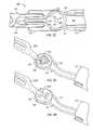
- FIGS. 2A , 2 B, and 2 Cshow a wrist mechanism in accordance with an embodiment of the invention using a pair of devises and four drive cables that slide on guide surfaces integrated into the clevises.
- FIGS. 3A and 3Billustrate jaws with cables attached using high friction paths in accordance with alternative embodiments of the invention.
- FIG. 4Aillustrates the movements of four drive cables that produce changes in the pitch, yaw, and grip of a wrist mechanism in accordance with an embodiment of the present invention.
- FIG. 4Bshows a perspective view illustrating pivot axes of the wrist mechanism of FIGS. 2A , 2 B, and 2 C when operated using the cable movements of FIG. 4A .
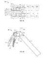
- FIGS. 5A and 5Brespectively show an exploded view and a cross-sectional view of a backend mechanism in accordance with an embodiment of the invention using gears and levers to move drive cables.
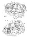
- FIG. 6shows a backend mechanism in accordance with an embodiment of the invention using pulleys, capstans, and gears to move drive cables.
- FIG. 7Ais a cross-sectional view of a wrist mechanism in a bipolar cautery instrument having electrical connections using brush type contacts in accordance with an embodiment of the invention.
- FIG. 7Billustrates one arrangement of guides for drive cables and electrical conductors in a bipolar cautery instrument in accordance with an embodiment of the invention.
- a wrist mechanism for a medical instrumentprovides three degrees of freedom (pitch, yaw, and grip) for an effector or tool and uses only four drive cables.
- the wrist architectureincludes a proximal clevis defining a pivot axis for pitch control and a distal clevis defining a pivot axis for yaw and grip control.
- the drive cablesslide on the surfaces of guide channels that are integrated into the clevises so that neither pulleys nor large cable wrap angles are required.
- the clevisescan include integral cable-guiding surfaces that cradle opposing sides of a cable, and the cable guiding surfaces can be curved in multiple directions to eliminate the need for large cable wrap angles that some prior wrist architectures require.
- the cable-guiding surfacesare additionally constructed or curved to avoid derailment of the cables and to keep the cables within the diameter constraint of a cannula through which the wrist mechanism may be inserted or removed during a minimally invasive medical procedure.
- the wrist mechanismcan provide the advantages of: requiring few cables and eliminating the space requirements of pulleys thereby allowing a clinically beneficial smaller working volume for the wrist mechanism; eliminating the cost of additional parts such as pulleys; and reducing friction when compared to wrist architectures with greater cable wrap angles.
- portions of the cables that pull jaws of the instrument together for grippingcan be stiffer, e.g., have a larger diameter, than the other cables in the instrument.
- portions of the cables that pull jaws of the instrument together for grippingcan be stiffer, e.g., have a larger diameter, than the other cables in the instrument.
- two out of the four cablescan have portions that are larger than corresponding portions of the other cables.
- the larger diameters of the selected cablespermit use of greater gripping force, without scaling up the size of the entire instrument.
- a wristed cauterizing instrumentcan use a brush or similar sliding contact to make electrical connections to jaws of the instrument.
- a distal cleviscan be made of electrically insulating material and provide a separator between opposite polarity jaws that share a common pivot axis.
- cables with non-conductive portionscan be attached to the jaws using a high friction path. Use of a high friction path can simplify instrument assembly and avoid the need to employ a crimp or similar structure that may be difficult to reliably attach to non-conductive cable material.
- the four drive cables of a wrist mechanismconnect to three motor-driven axes in a backend mechanism.
- the backend mechanismworks cooperatively with the wrist mechanism to achieve robotic control of the pitch, yaw, and grip of the effector.
- One embodiment of the backend mechanismuses two capstans, each with two cables wrapped about the capstan so that rotation of the capstan pulls in a length of one cable and reels out the same length of the other cable, and two robotic motorized degrees of freedom drive the capstans.
- the third degree of freedomis achieved from routing the cables through a set of pulleys, where the set of pulleys is configured to move as a group in proportion to a third robotic motorized degree of freedom.
- the motion of the group of pulleysis predominantly toward one capstan while away from the other, which has the effect of lengthening or feeding out one capstan's cable pair while shortening or pulling in the other pair of cables.
- Another embodiment of the backend mechanismhas two or more of the drive cables attached to the ends of respective levers.
- Gear mechanismscan move the cables by moving the ends of the levers opposite to the attachment of the cables or moving the respective pivots of the levers.
- motion of any one cablecan be matched by an equal and opposite motion of one or more of the other cables, and the cable connections can ensure that cable tension is maintained during all wrist motions, including motion possible when the instrument is separated from robotic control.
- the leversgenerally pull the cables along the instrument's length. This near linear motion also allows cables to be replaced by solid rods or tubes that may be less costly that stranded cable.
- FIG. 1shows an example of a robotically controlled system 100 capable of using a medical instrument in accordance with an embodiment of the present invention.
- System 100which may, for example, be a da Vinci® Surgical System available from Intuitive Surgical, Inc. includes multiple medical instruments 150 , each of which is mounted in a docking port on a robotic arm 130 .
- Instruments 150can be made interchangeable, so that the instruments 150 mounted on arms 130 can be selected for a particular medical procedure or changed during a medical procedure to provide the clinical functions needed.
- instruments 150can implement many functions including but not limited to forceps or graspers, needle drivers, and scissors of many different shapes and sizes.
- an instrument 150can be a bipolar cautery instrument.
- the docking portsgenerally include drive motors that provide mechanical power for operation of instruments 150 .
- the docking portsmay additionally include an electrical interface for communication with instruments 150 , for example, to identify the type of instrument in the docking port and to access parameters of the instrument.
- the electrical interfacemay also convey measurements such as measurements of the impedance of tissue, for example, for determination of parameters of a sealing operation.
- High voltage electrical systemssuch as generators for cauterizing or sealing instruments would typically connect to instruments 150 through separate connectors but could alternatively be provided through built-in circuits in control system 100 .
- Each instrument 150generally includes a transmission or backend mechanism 120 , a main tube 110 extending from the backend mechanism 120 , and a wrist mechanism 200 at the distal end of the main tube 110 .
- Drive cables and electrical conductors that are connected to wrist mechanism 200 in an instrument 150may extend through main tube 110 and connect to backend mechanism 120 .
- Backend mechanism 120typically provides a mechanical coupling of the drive cables to motorized axes provided by drive motors in control system 100 .
- Control system 100can thus control movement and tension in the drive cables as needed to position, orient, and operate wrist mechanism 200 .
- a processing system 140 of system 100can provide a doctor or other operating room personnel with a user interface enabling manipulation of arms 130 .
- an arm 130can be used to insert the end of a medical instrument 150 through a cannula in small incisions in a patient undergoing a medical procedure and to operate wrist mechanism 200 at a worksite inside the patient.
- the diameter of wrist mechanism 200 and main tube 110may be selected according to the size of the cannula with which the instrument will be used.
- wrist mechanism 200 and main tube 110are about 5 mm or about 8 mm in diameter to match the sizes of some existing cannula systems.
- Main tube 110is hollow and may contain both drive cables and electrical conductors that run from backend mechanism 120 to wrist mechanism 200 .
- Main tube 110may be rigid or flexible.
- a flexible main tube 100would be used, for example, for insertion through an endoscope or other guide or cannula that follows a natural lumen or otherwise curved path.
- many common types of minimally invasive medical proceduressuch as laparoscopic surgery employ straight cannulas for insertion and removal of instruments, permitting use of a rigid main tube 110 .
- a rigid main tube 110can provide a more solid base for use of wrist mechanism 200 during a medical procedure.
- a rigid and straight main tube 110also permits portions of drive cables extending through main tube 110 to be structures such as rods or tubes (e.g., hypotubes) that may provide better immunity to stretching or be less expensive.
- FIGS. 2A , 2 B, and 2 Cshow three views of a wrist mechanism 200 in accordance with an embodiment of the invention.
- wrist mechanism 200includes a proximal clevis 220 , a distal clevis 230 , and an effector 240 .
- Effector 240includes jaws 242 and 244 , each having a grip portion attached to a circular hub.
- Cables 251 , 252 , 253 , and 254are attached to effector 240 , extend along solid surfaces of guide channels in effector 240 , distal clevis 230 , and proximal clevis 220 , and from there extend back through main tube 110 to a backend mechanism (e.g., backend mechanism 120 of FIG. 1 ).
- the low part count of wrist mechanism 200 and the small number of drive cables 251 , 252 , 253 , and 254 employedfacilitate implementation of a small diameter for wrist mechanism 200 and main tube 110 . Additionally, the low part count allows cost effective use of wrist mechanism in a single-use instrument, i.e., an instrument that is disposed of after a single medical procedure, instead of being an instrument that must be sterilized for subsequent use.
- FIG. 2BThe partial cutaway view of wrist mechanism 200 in FIG. 2B shows how proximal clevis 220 can extend into and attach to main tube 110 .
- a pin 225 in proximal clevis 220attaches distal clevis 230 to proximal clevis 220 but allows distal clevis 230 to rotate about a pivot axis (sometimes referred to herein as the pitch axis) defined by pin 225 .
- Proximal clevis 220includes guide channels 222 for cables 251 , 252 , 253 , and 254 , and openings 224 of the guide channels 222 provide a range of motion for cables 251 , 252 , 253 , and 254 that directs cables 251 , 252 , 253 , and 254 into guide channels 232 of proximal clevis 230 .
- openings 224 of guide channels 222are narrow in the direction parallel to pin 225 in order to direct cables 251 , 252 , 253 , and 254 into respective guide channels 232 in distal clevis 230 but fan out in a direction perpendicular to pin 225 to keep cable friction low over the range of pitch angles that wrist mechanism 200 provides for distal clevis 230 .
- openings 234 of guide channels 232 nearest proximal clevis 220are narrow in a direction parallel to the pitch axis and pin 225 but fan out in a direction perpendicular to pin 225 to accommodate pitch rotations and avoid pinching cables 251 , 252 , 253 , and 254 .
- Guide channels 232 in distal clevis 230define a radius about pin 225 at which cables 251 , 252 , 253 , and 254 act on distal clevis 230 when rotating distal clevis 230 about pin 225 , i.e., about the pitch axis.
- guide channels 232In order for the moment arm of the torque applied by the cables to be constant throughout the range of pitch motion of wrist mechanism 200 , guide channels 232 have surfaces approximately in the shape of circular arcs.
- cable 253has a portion that rests against a lower guide surface subtending a circular arc about the pitch axis of pin 225 , and the distance between the pitch axis and the contact point of cable 253 on the lower surface of guide channel 232 is the moment arm for torque applied through cable 253 .
- distal clevis 230rotates clockwise when the backend mechanism pulls in cable 253 . If clockwise rotation continues from the illustrated position, cable 253 will remain on the surface and act at a constant moment arm until distal clevis 230 reaches the limit of its range of motion. Further, through the entire motions, the surfaces of guide channels 232 that are circular arcs pull in and play out equal lengths of cable as distal clevis 230 rotate, thereby avoiding cable slack.
- the cross-section of distal clevis 230 in FIG. 2Cfurther illustrates how guide channels 232 extend through distal clevis 230 and direct cables 251 , 252 , 253 , and 254 into circular guide channels 246 that are integrated into jaws 242 and 244 of effector 240 .
- four guide channels 232tunnel through distal clevis 230 for the four cables 251 , 252 , 253 , and 254 .
- Openings 236 of guide channels 232 nearest effector 240direct cables 251 , 252 , 253 , and 254 into respective guide channels 246 in jaws 242 and 244 .
- a pin 235 in distal clevis 230is perpendicular to pin 225 and defines a pivot axis, sometimes referred to as the yaw axis or grip axis, for effector 240 as a whole or jaws 242 and 244 individually.
- the yaw axis and the grip axiscoincide in wrist mechanism 200 .
- Guide channels 246 of jaws 242 and 244are circular and centered on pin 235 , so that the radius of channels 246 is the moment arm for torques that cables 251 , 252 , 253 , and 254 apply to jaws 242 and 244 when rotating jaws 242 and 244 or when maintaining a gripping force of jaws 242 and 244 .
- grippingis used herein in a general sense since the action of jaws 242 and 244 depend on the work tips of jaws 242 and 244 .
- the working tips of jaws 242 and 244have a surface for gripping and may be used, for example, in forceps or cautery applications.
- “gripping,” which closes jaws 242 and 242may be a cutting action when the tips of jaws 243 and 244 are blades that cooperatively cut as a scissors. Gripping can thus perform different functions depending on the nature of effector 240 .
- the paths of cables 251 , 252 , 253 , and 254 through wrist mechanism 200do not employ pulleys. Instead of pulleys, wrist mechanism 200 guides cables 251 , 252 , 253 , and 254 as described above using solid surfaces (i.e., the surfaces of guide channels 222 and 232 ) that are integral to devises 220 and 230 . At some points, the guiding surfaces cradle opposing sides of the cable. For example, top and bottom surfaces of cable 253 as shown in FIG. 2C contact guide surface 232 at an inflection point 237 where the curvature of cable 253 changes.
- the solid guide surfacesare also curved to eliminate the need for large cable wrap angles and to maintain a fixed cable radius or moment arm.
- the surfaces of guide channels 222 and 232can additionally be shaped to retain (or avoid derailment of) cables 251 , 252 , 253 , and 254 and to keep cables 251 , 252 , 253 , and 254 within the diameter constraint of a cannula through which wrist mechanism 200 passes during a minimally invasive medical procedure.
- Guiding cables 251 , 252 , 253 , and 254experience less friction when compared to wrist mechanisms with larger cable wrap angles. Friction of cables 251 , 252 , 253 , and 254 against distal clevis 230 and elsewhere may also be reduced through selection of the materials used.
- distal clevis 230can be made of a plastic that provides low friction against the material of cables 251 , 252 , 253 , and 254 .
- cables 251 , 252 , 253 , and 254include portions of stranded metal cable that may be swaged to provide smoother cable surfaces that lower friction.
- the reduced cable frictionallows pulleys to be deleted while maintaining clinically acceptable forces, torques, and precision and fidelity of motion for wrist mechanism 200 . Avoiding the use of pulleys reduces the space requirements of wrist mechanism 200 , allowing wrist mechanism 200 to have a clinically beneficial smaller working volume. Eliminating pulleys also reduces the cost.
- Cables 251 and 252attach to jaw 242 of effector 240
- cables 253 and 254attach to jaw 244 of effector 240
- the attachment of cables 251 and 252 to jaw 242is such that pulling in a length of one cable 251 or 252 while releasing the same length of the other cable 252 or 251 causes jaw 242 to rotate about pin 235
- the attachment of cables 253 and 254 to jaw 244is such that pulling in a length of one cable 253 or 254 while releasing the same length of the other cable 254 or 253 causes jaw 244 to rotate about pin 235 .
- Many techniques for attaching cables 251 , 252 , 253 , and 254could be employed.
- cables 251 and 252are opposite end portions of a cable loop that extends around circular arc about pin 235 that guide channel 246 defines in jaw 242 (or 244 ), and an attachment can be created by a knot tied in or a crimp fastened on the loop and fit into a matching notch (not shown) in guide channel 246 .
- a crimpto some cable materials, e.g., non-conductive cable materials can present challenges.
- the cable loopmay terminate through a high-friction pathway in jaw 242 or 244 , so that friction prevents cables 251 , 252 , 253 , and 254 from slipping relative to jaws 242 or 244 .
- FIG. 3Ashows a jaw 242 A attached to a cable loop 250 having portions that extend back into main tube 110 as to cables 251 and 252 .
- Loop 250extends along circular arcs of guide channel 246 of jaw 242 A into a high friction path 248 A, and back out along another circular arc of guide channel 246 .
- Path 248 Ais substantially co-planar with guide channel 246 and includes multiple sharp bends. Contact between cable loop 250 and the surface of jaw 242 A at the bends in path 248 A creates friction that prevents or resists sliding of cable 250 , each bend increasing the frictional force that acts to retain cable loop 250 against pullout. Cable loop 250 has no crimp attached.
- FIG. 3Bshows a jaw 242 B using an alternative high friction path 248 B in which cable loop 250 is threaded through several holes in jaw 242 B.
- Contact of cable loop 250 with jaw 242 B at the bends in cable loop 24813 (including at locations where cable loop 250 passes through jaw 242 B)creates friction that resists or prevents sliding of cable loop 250 . Accordingly, a crimp is not required to attach cable loop 250 to jaw 242 B.
- Assembly of a wrist mechanism using high friction path 248 Brequires threading of cable through holes in jaw 242 B, but once threaded, cable loop 250 is solidly retained in jaw 242 B, which may make assembly of a wrist using high friction path 248 B of FIG. 3B simpler than assembly of a wrist using high friction path 248 A of FIG. 3A .
- the jaw attachments without crimpseliminate the space requirement of crimps and the cost associated with crimping.
- the attachments without crimpsare also advantageous for some cable materials (e.g. non-metallic cables) for which crimping can be troublesome.
- non-metallic cablescan be useful as electrical insulators in cauterizing instruments. Even instruments that do not require electrical insulation, non-metallic cables may provide reduced friction, wear, and particulate generation against mating surfaces in the wrist mechanism.
- FIG. 4Ashows a simplified view of wrist mechanism 200 and illustrates processes for changing the pitch, yaw, and grip of jaws 242 and 244 .
- the illustrated processescan generally be performed one at a time or simultaneously in any desired combination to change the pitch, yaw, and grip of mechanism 200 .
- FIG. 4Bshows wrist mechanism 200 in more detail to illustrate rotation axes of wrist mechanism 200 and is described here simultaneously with FIG. 4A .
- Pitch axis rotationsi.e., rotations 425 in FIG. 4B
- a backend mechanism(not shown) pulls in identical lengths of cables 253 and 254 while releasing the same lengths of cables 251 and 252 .
- Cables 253 and 254apply forces to distal clevis 230 at moment arms defined by the guide channels of cables 253 and 254 through distal clevis 230 .
- the backend mechanismpulls in identical lengths of cables 251 and 252 while releasing the same lengths of cables 253 and 254 .
- Yaw rotationscorresponds to both rotating jaws 242 and 244 in the same direction and through the same angle.
- the backend mechanism pulling in a length of cable 252 and releasing an equal length of cable 251will cause jaw 242 to rotate in a clockwise direction about the axis of pin 235 .
- the guide channel in jaw 242defines the moment arm at which cable 252 applies a force jaw 242 , and the resulting torque causes jaw 242 to rotate clockwise and cables 251 and 252 to slide on the solid surface of guide channels in distal clevis 230 .
- jaw 244will rotate clockwise through an angle that is the same as the angle through which jaw 242 rotates. Accordingly, jaws 242 and 244 maintain their positions relative to each other and rotate as a unit through a yaw angle. Counterclockwise rotation of the effector including jaws 242 and 244 is similarly accomplished when the backend mechanism pulls in equal lengths of cables 251 and 253 while releasing the same lengths of cables 252 and 254 .
- Grip rotationsi.e., rotations 445 in FIG. 4B
- the backend mechanismpulls in equal lengths of cables 251 and 254 while releasing the same lengths of cables 252 and 253 , causing jaws 242 and 244 to rotate in opposite directions away from each other.
- the backend mechanismpulls in equal lengths of cables 252 and 253 while releasing the same lengths of cables 251 and 254 , causing jaws 242 and 244 to rotate in opposite directions toward each other.
- the tension in cables 252 and 253can be kept greater than the tension in cables 251 and 254 in order to maintain gripping forces.
- FIG. 4Aillustrates that portions 452 and 453 of cables 252 and 253 , respectively, can be made stiffer or thicker than corresponding portions of cables 251 and 254 to accommodate the higher or maintained tensions used for gripping. This can be achieved by fusing the ends of cable loops corresponding to cable 252 or 253 with heavier material.
- portions of cables 251 , 252 , 253 , and 254 having larger flexing during cable movementcan be made of a flexible material such as a stranded metal cable.
- Relatively straight portions of each cablein some embodiments can be less flexible material such as hypotubes or similar structures that have advantages in cost and immunity to stretching, and in such an embodiment, larger hypotubes can be used for portions 452 and 453 of cables 252 and 253 .
- the effective stiffness of each of the four drive cables 251 , 252 , 253 , and 254can thus be controlled advantageously for improved clinical performance.
- the effective stiffness of drive cables 252 and 253 that cause jaws 242 and 244 to closeis greater than the stiffness of drive cables 251 and 252 that cause jaws 242 and 244 to open. This arrangement minimizes cable slack, improving the fidelity of motion of wrist mechanism 200 .
- Materials, diameters, and lengthsare controlled to affect desired stiffness. Not using the larger structures in cables 251 and 254 saves cost and space.
- FIG. 5Ashows an exploded view of a portion of a backend mechanism 500 in accordance with an embodiment of the invention predominantly employing gears and levers to control movement of a wrist mechanism.
- the illustrated portion of backend mechanism 500includes a chassis 510 , three drive shafts 512 , 513 , and 514 , three toothed components 520 , 530 , and 540 , and two levers 550 and 560 and couples to four drive cables 571 , 572 , 573 , and 574 .
- the components 510 , 520 , 530 , 540 , 550 , and 560can be made of any suitably durable material such as molded or machined plastic or metal depending on the required loads and tolerances of the individual components.
- cables 571 , 572 , 573 , and 574can correspond to cables 251 , 252 , 253 , and 254 and connect to a wrist mechanism of the type described above with reference to FIGS. 2A , 2 B, and 2 C.
- backend mechanism 500can more generally be used in any instrument for which connection of four cables to three motor driven axes is desired.
- Chassis 510may have a footprint chosen for connection to a robotic control system containing motors that operate drive shafts 512 , 513 , and 514 .
- chassis 510may be shaped such that drive shafts 512 , 513 , and 514 when fit into chassis 510 are positioned to be engaged and rotated by a robotic control system such as the da Vinci® Surgical System.
- Toothed component 520acts as a pinion that engages a rack portion of toothed component 520 .
- Toothed component 520is attached to cable 572 and moves in a straight line to pull in or release a length of cable 572 as drive shaft 512 turns.
- Toothed component 520also includes an arm containing an adjustment screw 522 that contacts lever 550 .
- adjustment screw 522contacts lever 550 at an end opposite to where cable 571 attaches to lever 550 .
- a pivot point or fulcrum for lever 550is on toothed component 540 that acts as a rocker arm as described further below.
- adjustment screw 522causes or permits rotation of lever 550 about the pivot point so that lever 550 can pull in or release cable 571 .
- the connection of cable 571 to lever 550 and the contact point of adjustment screw 522 on lever 550can be made equidistant from the pivot point of lever 550 , so that when toothed component 520 pulls in (or releases) a length of cable 572 , lever 550 releases (or pulls in) the same length of cable 571 .
- Adjustment screw 522permits adjustment of the tension in cables 571 and 572 by controlling the orientation of lever 550 relative to the position of toothed component 520 .
- Toothed component 530similarly acts as a pinion that engages a rack portion of toothed component 530 .
- Toothed component 530is attached to drive cable 573 and moves in a straight line to pull in or release a length of cable 573 as drive shaft 513 turns.
- Toothed component 520also includes an arm containing an adjustment screw 532 that contacts lever 560 at an end opposite to where cable 574 attaches to lever 560 .
- a pivot point or fulcrum for lever 560is on toothed component 540 , and the distance of the connection of cable 574 from the pivot point of lever 560 can be made the same as the distance from the pivot point of lever 560 to the contact point of adjustment screw 532 on lever 560 .
- Adjustment screw 523permits adjustment of the tension in cables 573 and 574 by controlling the orientation of lever 560 relative to the position of toothed component 530 .
- Drive shafts 512 and 513can be operated to change the yaw angle or the grip of a wrist mechanism using the processes described above. For example, when cables 571 , 572 , 573 , and 574 respectively correspond to cables 251 , 252 , 253 , and 254 of FIG. 4A , turning drive shafts 512 and 513 at the same speed in the same direction or in opposite directions will change the grip or yaw of wrist mechanism 200 .
- Toothed component 540has a pivot attached to chassis 510 , so that as drive shaft 514 turns, toothed component 540 rotates about pivot 542 . Toothed component 540 also includes protrusions (not visible in FIG. 5A ) that act as pivot points for levers 550 and 560 . These protrusions can be located equidistant from pivot 542 , so that as toothed component 540 rotates one pivot moves closer to the wrist mechanism and the other pivot moves further from the wrist mechanism by an equal amount.
- Backend mechanism 500can thus be used to perform a pitch change as described above with reference to FIG. 4A when cables 571 , 572 , 573 , and 574 respectively correspond to cables 251 , 252 , 253 , and 254 , but the pitch change process requires coordinated rotations of all three gears 512 , 513 , and 514 .
- Such coordinated rotationscan be implemented in software of a robotic control system.
- FIG. 5Bshows a cross-sectional view of backend mechanism 500 when assembled with additional components not shown in FIG. 5A .
- backend mechanism 500includes drive shafts 512 , 513 , and 514 that respectively engage toothed components 520 , 530 , and 540 , and a robotic control system coupled to backend 500 can rotate drive shafts 512 , 513 , and 514 to control the pitch, yaw, and grip of a wrist mechanism (not shown).
- Cables 571 , 572 , 573 , and 574extend from the wrist mechanism (not shown) at a distal end of a main tube 110 , through main tube 110 and into backend mechanism 500 .
- Main tube 110is attached in backend mechanism 500 to a helical gear 580 , which is coupled to a drive shaft 511 through an intervening helical gear 582 .
- a control systemrotates drive shaft 511
- helical gears 582 and 580rotate main tube 110 and thereby change the roll angle of the effector at the distal end of main tube 110 .
- FIG. 5Balso shows a circuit board 590 , which may be included in backend mechanism 500 for electrical connection to a robotic control system.
- Circuit board 590can include memory or other circuitry that sends an identification signal to the control system to indicate which instrument is connected to the control system and/or to provide key parameters that the control system may need for proper operation of the instrument.
- Connection to electrical components of the effectore.g., to energize a cauterizing instrument or to relay sensor measurements, could be in circuit board 590 .
- a separate electrical connectionmay be desired for energizing the effector, particularly when high voltages are required.
- Backend mechanism 500 as illustrated in FIG. 5Balso includes a cover 516 that encloses mechanical and electrical components of backed mechanism 500 .
- Two levers 518can be used to disengage backend mechanism 500 from a robotic control system.
- FIG. 6shows a backend mechanism 600 in accordance with an embodiment of the invention employing cables, pulleys, and capstans.
- Backend mechanism 600includes a chassis 610 , four drive shafts 611 , 612 , 613 , and 614 , a pair of capstans 620 and 630 , a rocker arm 640 on which a first pair of pulleys 642 and a second pair of pulleys 643 are mounted, helical gears 580 and 582 , and a circuit board 590 .
- cables 671 , 672 , 673 , and 674which are connected to a wrist mechanism (not shown), extend through a main tube 110 into backend mechanism 600 .
- Cables 671 , 672 , 673 , and 674can respectively correspond to cables 251 , 252 , 253 , and 254 , which are connected to wrist mechanism 200 of FIGS. 2A , 2 B, and 2 C.
- backend mechanism 600can more generally be used in any instrument for which connection of four cables to three motor driven axes is desired.
- chassis 610is generally selected to have a footprint corresponding to a mounting on a robotic control system.
- Backend mechanismmay thus be fitted to a control system so that drive shafts 611 , 612 , 613 , and 614 are mechanically coupled to motors in the control system.
- the control systemis then able to rotate drive shafts 611 , 612 , 613 , and 614 through precise angles that may be selected by software to achieve the desired operation or movement of the instrument.
- Cables 671 and 672pass from main tube 110 , wind around one or more pulleys 642 , and wrap around capstan 620 .
- the wrapping of cables 671 and 672 around capstan 620is such that when capstan 620 turns, a length of one cable 671 or 672 is pulled in and an equal length of the other cable 672 or 671 fed out.
- cables 673 and 674pass from main tube 110 , wind around one or more pulleys 643 , and are wrapped around capstan 630 , so that when capstan 630 turns a length of one cable 673 or 674 is pulled in and an equal length of the other cable 674 or 673 is fed out.
- Drive shafts 612 and 613are respectively coupled to turn capstan 620 and 630 .
- a control systemcan thus turn drive shafts 612 and 613 to change the yaw angle or the grip of a wrist mechanism using the processes described above.
- cables 671 , 672 , 673 , and 674respectively correspond to cables 251 , 252 , 253 , and 254 of FIG. 4A , turning drive shafts 612 and 613 at the same speed in the same direction or in opposite directions will change the grip or yaw of wrist mechanism 200 .
- Pulleys 642 and 643are mounted on rocker arm 640 .
- Rocker arm 640has a sector gear portion that engages drive shaft 614 and is coupled to chassis 610 to rotate or rock about a pivot axis when drive shaft 614 turns.
- the sector gear portion and pivot of rocker arm 640are designed so that rotation of rocker arm 640 primarily causes one set of pulleys 642 or 643 to move toward its associated capstan 620 or 630 and the other set of pulleys 643 or 642 to move away from its associated capstan 630 or 620 . This effectively pulls in lengths of one pair of cables 671 and 672 or 673 and 674 and releases an equal length of the other pair of cables 673 and 674 or 671 and 672 .
- Backend mechanism 600simply through rotation of drive shaft 614 can thus change the pitch in a wrist mechanism as described above with reference to FIG. 4A when cables 671 , 672 , 673 , and 674 respectively correspond to cables 251 , 252 , 253 , and 254 .
- Backend mechanism 600can control the roll angle of a wrist mechanism at the distal end of main tube 110 using drive shaft 611 to turn helical gears 582 and 580 .
- Helical gears 580 and 581are coupled to main tube 110 and operate in the same manner as described above.
- Cables 671 , 672 , 673 , and 674 in backend mechanism 600wind or wrap around pulleys 642 and 643 and capstans 620 and 630 and must be able to flex when capstans 620 and 630 rotate. Accordingly, portions of cables 671 , 672 , 673 , and 674 in backend mechanism 600 require flexibility and may be, for example, stranded metal cable that can be flexed repeatedly around relatively sharp turns without damage.
- each cable 671 , 672 , 673 , and 674may include three portions, a stranded cable portion in the wrist mechanism, a more rigid portion (e.g., hypotube) extending through the straight portion of main tube 110 , and a second stranded cable portion in backend mechanism 600 .
- backend mechanism 500 of FIG. 5Bmoves cables 571 , 572 , 573 , and 574 in nearly linear motions and does not require significant flexing of cables 571 , 572 , 573 , and 574 around pulleys or other sharp bends.
- the potions of cables 571 , 572 , 573 , and 574 in backend mechanism 500can be relatively rigid structures such as hypotubes.
- Backend mechanism 600 of FIG. 6like backend mechanism 500 of FIG. 5B includes a circuit board 590 with circuits that provide an interface to a robotic control system as described above.
- High voltage connectionsare generally made through separate electrical connections and wires that may be run through backend mechanism 500 or 600 and run through main tube 110 to the effector.
- the instrumentis a bipolar cautery instrument and electrical wires or other electrical conductors (not shown) connect to a generator through connectors (not shown) on the back end mechanism and from there run with the drive cables through main tube 110 to the wrist mechanism at the distal end of main tube 110 .
- electrical energy for cauterycan be delivered through contacts, which engage jaws in the effector much the same manner as brushes in a motor.
- FIG. 7Ashows a cross-sectional view of a wrist mechanism 700 for a cautery instrument.
- Wrist mechanism 700includes a proximal clevis 220 , a distal clevis 230 rotatably attached to a pin 225 through proximal clevis 220 , and jaws 242 and 244 rotatably attached to a pin 235 through distal clevis 230 .
- Drive cables (not shown in FIG. 7A ) for wrist mechanism 700can follow guide channels in clevis 220 and 230 and attach to jaws 242 and 244 as described above with reference to FIGS. 2A , 2 B, and 2 C and can change the pitch, yaw, and grip of wrist mechanism 700 in the same manner described with reference to FIGS.
- the drive cables or at least the portion of the drive cables that contact jaw 242 or 244are preferably made of an insulating material. As mentioned above with reference to FIGS. 3A and 3B , the attachment of drive cables to jaws 242 and 244 can be made using high friction paths to avoid difficulties that may arise from crimping of non-conductive cables. Insulated electrical wires or other conductors 772 and 774 also feed through proximal clevis 220 and distal clevis 230 so that ends of wires 772 and 774 are respectively adjacent to jaws 242 and 244 . FIG.
- FIG. 7Bshows an end view of proximal clevis 220 illustrating how guide channels 222 for the drive cables can be positioned near an outer edge of proximal clevis 220 to provide room near the center axis of proximal clevis 220 for conduits 722 .
- Wires 772 and 774can thus be run through devises 220 and 230 without interfering with the drive cables.
- Contacts 782 and 784 as shown in FIG. 7Aare at the end of wires 772 and 774 and in electrical contact with respective jaws 242 and 244 .
- Contacts 782 and 784can be made of tempered or spring metal that is compressed to make good electrical contact with jaws 242 and 244 when jaws 242 and 244 are assembled into distal clevis 230 .
- contacts 782 and 784engage a constant-radius circumference at the proximal ends of respective jaws 242 and 244 , so that as jaws 242 or 244 rotate during a change of yaw angle or grip, contacts 782 and 784 remain in contact with the circular surface.
- both or either contact 782 and 784could be positioned to engage a flat side of jaw 242 or 244 perpendicular to the grip axis and pin 235 .
- An advantage of contacts 782 and 784is a reduction in the motion imparted to wires 772 and 774 .
- wires 772 and 774move only during pitch changes but not when the yaw or grip is being changed.
- a direct electrical contactattached wires move whenever the pitch, yaw, or grip changes.
- the reduction in movement of wires 772 and 774reduces the likelihood of damage to wires 772 and 774 from fatigue, contact with a foreign object, kinking, or wear.
- Contacts 782 and 784can be used to electrically energize jaws 242 and 244 with opposite polarity voltages to activate the cauterizing function of wrist mechanism 700 .
- wrist mechanism 700can be manipulated so that jaws 282 and 284 grip a vessel, thereby closing the vessel to be sealed.
- Conductors 772 and 774 and contacts 782 and 784can then energize jaws 282 and 284 with high frequency AC signals having opposite polarity. While the electrical energy is applied to jaws 242 and 244 , a current flows through the tissue gripped in jaws 242 and 244 , and the duration of the electrical signal can be selected so that the current cauterizes the tissue and seals the gripped vessel.
- Cauterycan also be used in other manners known in the art, for example, to cut or destroy tissue during a medical procedure.
- power for electrocauteryis generally from a high voltage (e.g., above about 250 volts) AC signal having a frequency above about 100 kHz.
- a coating on wires 772 and 774insulates the signal from the main tube and proximal clevis 220 so that neither is electrically energized.
- Wires 772 and 774are preferably stranded for flexibility and have an insulating coating of a material such as FEP, which provides a relatively high dielectric constant and low friction when a wire 772 or 774 move.
- Distal clevis 230in which contacts 782 and 784 reside, can be made out of an insulating material such as plastic (e.g., Ultem) or an insulating ceramic.
- pin 235which is in contact with both jaws 242 and 244 , is made of an insulating material such as a ceramic to avoid voltage leakage and prevent shorting between jaws 242 and 244 .
- jaws 242 and 244are positioned in cavities in insulating distal clevis 230 .
- a separator 732is integrated in distal clevis to provide electrical isolation between the opposite polarity jaws 242 and 244 .
- the cavitiescan provide sufficient isolation distance between jaws 242 and 244 , such that hermetic seals or separate encapsulation of each jaw 242 or 244 (as done in some prior cautery systems) is not required.
- Contacts such as 782 and 784could also be used in a monopolar cautery where both jaws 242 and 244 are at the same voltage, but separation between jaws 242 and 244 is not required for monopolar cautery.
- Many of the above described embodimentscan reduce the cost of a minimally invasive surgical instrument by reducing: the number of parts in the instrument; the complexity of the instrument; the cost of the materials used; the manufacturing difficulty of the parts; and the difficulty of the assembly of the instrument. Reducing cost has obvious benefits, but also enables the creation of single-use instruments that are cost competitive (per case) when compared against existing reusable instruments.
- a single-use instrumenthas further benefits of eliminating reprocessing/sterilization at the hospital and allows further cost saving during manufacture of the instruments because components do not need to be designed and verified for reprocessing.
- Embodiments of the invention that reduce the parts countcan also enable production of smaller instruments. This has clinical benefit by decreasing both the diameter and length of the wrist. Medical procedures may thus be able to use smaller incisions, and greater control of precision wrist manipulations may be possible.
- a bipolar endowrist cautery instrumentmay be fabricated with a 5-mm diameter, while previously, such instruments were only manufactured with a diameter 8-mm or larger.
Landscapes
- Health & Medical Sciences (AREA)
- Surgery (AREA)
- Engineering & Computer Science (AREA)
- Life Sciences & Earth Sciences (AREA)
- Medical Informatics (AREA)
- Robotics (AREA)
- Biomedical Technology (AREA)
- Heart & Thoracic Surgery (AREA)
- Nuclear Medicine, Radiotherapy & Molecular Imaging (AREA)
- Molecular Biology (AREA)
- Animal Behavior & Ethology (AREA)
- General Health & Medical Sciences (AREA)
- Public Health (AREA)
- Veterinary Medicine (AREA)
- Manipulator (AREA)
- Surgical Instruments (AREA)
Abstract
Description
Claims (17)
Priority Applications (2)
| Application Number | Priority Date | Filing Date | Title |
|---|---|---|---|
| US12/173,934US8821480B2 (en) | 2008-07-16 | 2008-07-16 | Four-cable wrist with solid surface cable channels |
| PCT/US2009/050678WO2010009221A2 (en) | 2008-07-16 | 2009-07-15 | Four-cable wrist with solid surface cable channels |
Applications Claiming Priority (1)
| Application Number | Priority Date | Filing Date | Title |
|---|---|---|---|
| US12/173,934US8821480B2 (en) | 2008-07-16 | 2008-07-16 | Four-cable wrist with solid surface cable channels |
Publications (2)
| Publication Number | Publication Date |
|---|---|
| US20100011901A1 US20100011901A1 (en) | 2010-01-21 |
| US8821480B2true US8821480B2 (en) | 2014-09-02 |
Family
ID=41402506
Family Applications (1)
| Application Number | Title | Priority Date | Filing Date |
|---|---|---|---|
| US12/173,934Active2033-07-02US8821480B2 (en) | 2008-07-16 | 2008-07-16 | Four-cable wrist with solid surface cable channels |
Country Status (2)
| Country | Link |
|---|---|
| US (1) | US8821480B2 (en) |
| WO (1) | WO2010009221A2 (en) |
Cited By (144)
| Publication number | Priority date | Publication date | Assignee | Title |
|---|---|---|---|---|
| US20160375587A1 (en)* | 2015-06-26 | 2016-12-29 | Haption | Secured motor-driven articulated arm with cable capstan |
| US20170105805A1 (en)* | 2014-07-10 | 2017-04-20 | Olympus Corporation | Medical instrument and adjustment method of medical instrument |
| US10092359B2 (en) | 2010-10-11 | 2018-10-09 | Ecole Polytechnique Federale De Lausanne | Mechanical manipulator for surgical instruments |
| US10265129B2 (en) | 2014-02-03 | 2019-04-23 | Distalmotion Sa | Mechanical teleoperated device comprising an interchangeable distal instrument |
| US10325072B2 (en) | 2011-07-27 | 2019-06-18 | Ecole Polytechnique Federale De Lausanne (Epfl) | Mechanical teleoperated device for remote manipulation |
| WO2019118337A1 (en) | 2017-12-14 | 2019-06-20 | Intuitive Surgical Operations, Inc. | Medical tools having tension bands |
| US10343291B2 (en)* | 2016-05-31 | 2019-07-09 | Olympus Corporation | Gripping mechanism and gripper |
| US10357320B2 (en) | 2014-08-27 | 2019-07-23 | Distalmotion Sa | Surgical system for microsurgical techniques |
| US10363055B2 (en) | 2015-04-09 | 2019-07-30 | Distalmotion Sa | Articulated hand-held instrument |
| WO2019173268A1 (en) | 2018-03-07 | 2019-09-12 | Intuitive Surgical Operations, Inc. | Low-friction, small profile medical tools having easy-to-assemble components |
| WO2019173267A1 (en) | 2018-03-07 | 2019-09-12 | Intuitive Surgical Operations, Inc. | Low-friction, small profile medical tools having easy-to-assemble components |
| US10413374B2 (en) | 2018-02-07 | 2019-09-17 | Distalmotion Sa | Surgical robot systems comprising robotic telemanipulators and integrated laparoscopy |
| US10548680B2 (en) | 2014-12-19 | 2020-02-04 | Distalmotion Sa | Articulated handle for mechanical telemanipulator |
| US10568709B2 (en) | 2015-04-09 | 2020-02-25 | Distalmotion Sa | Mechanical teleoperated device for remote manipulation |
| US10631886B2 (en) | 2014-04-24 | 2020-04-28 | Livsmed Inc. | Surgical instrument |
| US10646294B2 (en) | 2014-12-19 | 2020-05-12 | Distalmotion Sa | Reusable surgical instrument for minimally invasive procedures |
| US10695141B2 (en) | 2011-11-23 | 2020-06-30 | Livsmed Inc. | Surgical instrument |
| US10709467B2 (en) | 2014-10-02 | 2020-07-14 | Livsmed Inc. | Surgical instrument |
| US10722315B2 (en) | 2015-02-17 | 2020-07-28 | Livsmed Inc. | Instrument for surgery |
| US10786272B2 (en) | 2015-08-28 | 2020-09-29 | Distalmotion Sa | Surgical instrument with increased actuation force |
| US10864052B2 (en) | 2014-12-19 | 2020-12-15 | Distalmotion Sa | Surgical instrument with articulated end-effector |
| US10864049B2 (en) | 2014-12-19 | 2020-12-15 | Distalmotion Sa | Docking system for mechanical telemanipulator |
| US20200390507A1 (en)* | 2018-03-07 | 2020-12-17 | Intuitive Surgical Operations, Inc. | Low-friction medical tools having roller-assisted tension members |
| WO2020263949A1 (en)* | 2019-06-28 | 2020-12-30 | Auris Health, Inc. | Medical instruments including wrists with hybrid redirect surfaces |
| US10959792B1 (en) | 2019-09-26 | 2021-03-30 | Auris Health, Inc. | Systems and methods for collision detection and avoidance |
| US10993734B2 (en) | 2016-03-10 | 2021-05-04 | Hsiman Extensions Ltd. | Control unit for a medical device |
| US11039820B2 (en) | 2014-12-19 | 2021-06-22 | Distalmotion Sa | Sterile interface for articulated surgical instruments |
| US11058503B2 (en) | 2017-05-11 | 2021-07-13 | Distalmotion Sa | Translational instrument interface for surgical robot and surgical robot systems comprising the same |
| US11129686B2 (en)* | 2016-10-14 | 2021-09-28 | Cmr Surgical Limited | Driving arrangement for articulating a surgical instrument |
| WO2021195323A1 (en) | 2020-03-27 | 2021-09-30 | Intuitive Surgical Operations, Inc. | Systems and methods of controlling instruments |
| US11172999B2 (en) | 2017-11-14 | 2021-11-16 | Livsmed Inc. | Roll joint member for surgical instrument |
| WO2021236505A1 (en) | 2020-05-18 | 2021-11-25 | Intuitive Surgical Operations, Inc. | Devices and methods for stress/strain isolation on a force sensor unit |
| US11207145B2 (en) | 2016-07-14 | 2021-12-28 | Intuitive Surgical Operations, Inc. | Multi-cable medical instrument |
| US11272977B2 (en) | 2008-07-16 | 2022-03-15 | Intuitive Surgical Operations, Inc. | Medical instrument electrically energized using drive cables |
| WO2022056213A1 (en) | 2020-09-14 | 2022-03-17 | Intuitive Surgical Operations, Inc. | Devices and methods for compact, redundant inductive force sensor |
| US11344381B2 (en) | 2015-02-17 | 2022-05-31 | Livsmed Inc. | Instrument for surgery |
| US11357586B2 (en) | 2020-06-30 | 2022-06-14 | Auris Health, Inc. | Systems and methods for saturated robotic movement |
| WO2022132885A1 (en) | 2020-12-17 | 2022-06-23 | Intuitive Surgical Operations, Inc. | Devices and methods for force sensing unit with shaft translation and roll |
| US11369386B2 (en) | 2019-06-27 | 2022-06-28 | Auris Health, Inc. | Systems and methods for a medical clip applier |
| US11382650B2 (en) | 2015-10-30 | 2022-07-12 | Auris Health, Inc. | Object capture with a basket |
| US11432891B2 (en) | 2015-06-03 | 2022-09-06 | Covidien Lp | Offset instrument drive unit |
| US11432890B2 (en) | 2018-01-04 | 2022-09-06 | Covidien Lp | Systems and assemblies for mounting a surgical accessory to robotic surgical systems, and providing access therethrough |
| US11439419B2 (en) | 2019-12-31 | 2022-09-13 | Auris Health, Inc. | Advanced basket drive mode |
| USD963851S1 (en) | 2020-07-10 | 2022-09-13 | Covidien Lp | Port apparatus |
| US11446099B2 (en) | 2016-06-03 | 2022-09-20 | Covidien Lp | Control arm for robotic surgical systems |
| US11464593B2 (en) | 2016-06-03 | 2022-10-11 | Covidien Lp | Passive axis system for robotic surgical systems |
| US11484372B2 (en) | 2019-02-15 | 2022-11-01 | Covidien Lp | Articulation mechanisms for surgical instruments such as for use in robotic surgical systems |
| US11510747B2 (en) | 2017-05-25 | 2022-11-29 | Covidien Lp | Robotic surgical systems and drapes for covering components of robotic surgical systems |
| US11517183B2 (en) | 2015-10-23 | 2022-12-06 | Covidien Lp | Surgical system for detecting gradual changes in perfusion |
| US11523509B2 (en) | 2016-05-26 | 2022-12-06 | Covidien Lp | Instrument drive units |
| US11529203B2 (en) | 2015-09-25 | 2022-12-20 | Covidien Lp | Robotic surgical assemblies and instrument drive connectors thereof |
| US11534249B2 (en) | 2015-10-30 | 2022-12-27 | Auris Health, Inc. | Process for percutaneous operations |
| US11540889B2 (en) | 2017-11-10 | 2023-01-03 | Intuitive Surgical Operations, Inc. | Tension control in actuation of jointed instruments |
| US11547508B2 (en) | 2016-05-26 | 2023-01-10 | Covidien Lp | Robotic surgical assemblies |
| US11553974B2 (en) | 2017-05-25 | 2023-01-17 | Covidien Lp | Systems and methods for detection of objects within a field of view of an image capture device |
| US11553984B2 (en) | 2016-06-03 | 2023-01-17 | Covidien Lp | Robotic surgical system with an embedded imager |
| US11571229B2 (en) | 2015-10-30 | 2023-02-07 | Auris Health, Inc. | Basket apparatus |
| US11576562B2 (en) | 2016-04-07 | 2023-02-14 | Titan Medical Inc. | Camera positioning method and apparatus for capturing images during a medical procedure |
| US11576739B2 (en) | 2018-07-03 | 2023-02-14 | Covidien Lp | Systems, methods, and computer-readable media for detecting image degradation during surgical procedures |
| US11576732B2 (en) | 2017-11-13 | 2023-02-14 | Vicarious Surgical Inc. | Virtual reality wrist assembly |
| US11576733B2 (en) | 2019-02-06 | 2023-02-14 | Covidien Lp | Robotic surgical assemblies including electrosurgical instruments having articulatable wrist assemblies |
| US11583358B2 (en) | 2017-09-06 | 2023-02-21 | Covidien Lp | Boundary scaling of surgical robots |
| US11586106B2 (en) | 2018-12-28 | 2023-02-21 | Titan Medical Inc. | Imaging apparatus having configurable stereoscopic perspective |
| US11596489B2 (en) | 2015-03-10 | 2023-03-07 | Covidien Lp | Measuring health of a connector member of a robotic surgical system |
| US11612446B2 (en) | 2016-06-03 | 2023-03-28 | Covidien Lp | Systems, methods, and computer-readable program products for controlling a robotically delivered manipulator |
| US11615884B2 (en) | 2018-03-06 | 2023-03-28 | Digital Surgery Limited | Techniques for virtualized tool interaction |
| US11618171B2 (en) | 2013-12-11 | 2023-04-04 | Covidien Lp | Wrist and jaw assemblies for robotic surgical systems |
| US11622824B2 (en) | 2015-06-16 | 2023-04-11 | Covidien Lp | Robotic surgical system torque transduction sensing |
| US11628024B2 (en) | 2018-03-08 | 2023-04-18 | Covidien Lp | Surgical robotic systems |
| US11628028B2 (en) | 2018-12-31 | 2023-04-18 | Asensus Surgical Us, Inc. | Articulating surgical instrument |
| US11628022B2 (en) | 2017-09-05 | 2023-04-18 | Covidien Lp | Collision handling algorithms for robotic surgical systems |
| US11633243B2 (en) | 2018-10-10 | 2023-04-25 | Titan Medical Inc. | Instrument insertion system, method, and apparatus for performing medical procedures |
| WO2023076468A1 (en) | 2021-10-29 | 2023-05-04 | Intuitive Surgical Operations, Inc. | Systems for control of a surgical system |
| US11647888B2 (en) | 2018-04-20 | 2023-05-16 | Covidien Lp | Compensation for observer movement in robotic surgical systems having stereoscopic displays |
| US11666395B2 (en) | 2015-06-23 | 2023-06-06 | Covidien Lp | Robotic surgical assemblies |
| US11690691B2 (en) | 2017-02-15 | 2023-07-04 | Covidien Lp | System and apparatus for crush prevention for medical robot applications |
| US11717355B2 (en) | 2019-01-29 | 2023-08-08 | Covidien Lp | Drive mechanisms for surgical instruments such as for use in robotic surgical systems |
| US11717361B2 (en) | 2017-05-24 | 2023-08-08 | Covidien Lp | Electrosurgical robotic system having tool presence detection |
| US11737845B2 (en) | 2019-09-30 | 2023-08-29 | Auris Inc. | Medical instrument with a capstan |
| US11737835B2 (en) | 2019-10-29 | 2023-08-29 | Auris Health, Inc. | Braid-reinforced insulation sheath |
| US11779413B2 (en) | 2015-11-19 | 2023-10-10 | Covidien Lp | Optical force sensor for robotic surgical system |
| US20230320795A1 (en)* | 2020-09-15 | 2023-10-12 | Covidien Lp | Surgical robotic system for controlling wristed instruments |
| US11839441B2 (en) | 2017-05-25 | 2023-12-12 | Covidien Lp | Robotic surgical system with automated guidance |
| US11839969B2 (en) | 2020-06-29 | 2023-12-12 | Auris Health, Inc. | Systems and methods for detecting contact between a link and an external object |
| US11844585B1 (en) | 2023-02-10 | 2023-12-19 | Distalmotion Sa | Surgical robotics systems and devices having a sterile restart, and methods thereof |
| US11896330B2 (en) | 2019-08-15 | 2024-02-13 | Auris Health, Inc. | Robotic medical system having multiple medical instruments |
| US11896336B2 (en) | 2015-02-17 | 2024-02-13 | Livsmed Inc. | Instrument for surgery |
| US11925429B2 (en) | 2015-02-19 | 2024-03-12 | Covidien Lp | Repositioning method of input device for robotic surgical system |
| US11931901B2 (en) | 2020-06-30 | 2024-03-19 | Auris Health, Inc. | Robotic medical system with collision proximity indicators |
| US11948226B2 (en) | 2021-05-28 | 2024-04-02 | Covidien Lp | Systems and methods for clinical workspace simulation |
| US11950872B2 (en) | 2019-12-31 | 2024-04-09 | Auris Health, Inc. | Dynamic pulley system |
| US11957371B2 (en) | 2014-08-13 | 2024-04-16 | Covidien Lp | Robotically controlling mechanical advantage gripping |
| WO2024081300A1 (en) | 2022-10-12 | 2024-04-18 | Intuitive Surgical Operations, Inc. | Surgical system haptic feedback systems |
| US11963730B2 (en) | 2021-11-30 | 2024-04-23 | Endoquest Robotics, Inc. | Steerable overtube assemblies for robotic surgical systems |
| US11986261B2 (en) | 2018-04-20 | 2024-05-21 | Covidien Lp | Systems and methods for surgical robotic cart placement |
| WO2024107655A1 (en) | 2022-11-15 | 2024-05-23 | Intuitive Surgical Operations, Inc. | Force sensing medical instrument |
| US11998288B2 (en) | 2018-09-17 | 2024-06-04 | Covidien Lp | Surgical robotic systems |
| US12029523B2 (en) | 2017-12-01 | 2024-07-09 | Covidien Lp | Drape management assembly for robotic surgical systems |
| US12030195B2 (en) | 2020-05-27 | 2024-07-09 | Covidien Lp | Tensioning mechanisms and methods for articulating surgical instruments such as for use in robotic surgical systems |
| US12029510B2 (en) | 2018-01-10 | 2024-07-09 | Covidien Lp | Determining positions and conditions of tools of a robotic surgical system utilizing computer vision |
| US12064196B2 (en) | 2021-11-30 | 2024-08-20 | Endoquest Robotics, Inc. | Master control systems for robotic surgical systems |
| WO2024178115A1 (en) | 2023-02-22 | 2024-08-29 | Intuitive Surgical Operations, Inc. | Medical instrument |
| US12102403B2 (en) | 2018-02-02 | 2024-10-01 | Coviden Lp | Robotic surgical systems with user engagement monitoring |
| US12114945B2 (en) | 2021-09-13 | 2024-10-15 | Distalmotion Sa | Instruments for surgical robotic system and interfaces for the same |
| US12138003B2 (en) | 2019-06-25 | 2024-11-12 | Auris Health, Inc. | Medical instruments including wrists with hybrid redirect surfaces |
| US12138001B2 (en) | 2021-11-30 | 2024-11-12 | Endoquest Robotics, Inc. | Patient console 5-degree of freedom positioning systems |
| US12144537B2 (en) | 2017-08-16 | 2024-11-19 | Covidien Lp | End effector including wrist assembly and electrosurgical tool for robotic surgical systems |
| US12144571B2 (en) | 2021-11-30 | 2024-11-19 | Endoquest Robotics, Inc. | Force transmission systems for robotically controlled medical devices |
| US12150663B2 (en)* | 2021-07-16 | 2024-11-26 | Livsmed Inc. | End tool of surgical instrument, and electrocauterization surgical instrument comprising same |
| US12150729B1 (en) | 2024-02-02 | 2024-11-26 | Panda Surgical Limited | Handheld surgical systems with interchangeable dexterous end-effectors |
| US12178528B2 (en) | 2018-09-14 | 2024-12-31 | Covidien Lp | Surgical robotic systems and methods of tracking usage of surgical instruments thereof |
| US12186040B2 (en) | 2018-09-17 | 2025-01-07 | Covidien Lp | Surgical robotic systems |
| US12186007B2 (en) | 2021-11-30 | 2025-01-07 | Endoquest Robotics, Inc. | Disposable end effectors |
| US12207894B2 (en) | 2017-09-08 | 2025-01-28 | Covidien Lp | Energy disconnect for robotic surgical assemblies |
| US12223629B2 (en) | 2019-09-11 | 2025-02-11 | Covidien Lp | Systems and methods for smoke-reduction in images |
| USD1066383S1 (en) | 2023-01-13 | 2025-03-11 | Covidien Lp | Display screen with graphical user interface |
| USD1066380S1 (en) | 2023-01-13 | 2025-03-11 | Covidien Lp | Display screen with graphical user interface |
| USD1066405S1 (en) | 2023-01-13 | 2025-03-11 | Covidien Lp | Display screen with graphical user interface |
| USD1066382S1 (en) | 2023-01-13 | 2025-03-11 | Covidien Lp | Display screen with graphical user interface |
| USD1066381S1 (en) | 2023-01-13 | 2025-03-11 | Covidien Lp | Display screen with graphical user interface |
| USD1066379S1 (en) | 2023-01-13 | 2025-03-11 | Covidien Lp | Display screen with graphical user interface |
| USD1066404S1 (en) | 2023-01-13 | 2025-03-11 | Covidien Lp | Display screen with graphical user interface |
| USD1066378S1 (en) | 2023-01-13 | 2025-03-11 | Covidien Lp | Display screen with graphical user interface |
| US12256890B2 (en) | 2019-12-23 | 2025-03-25 | Covidien Lp | Systems and methods for guiding surgical procedures |
| US12262964B2 (en) | 2020-02-26 | 2025-04-01 | Covidien Lp | Robotic surgical instrument including linear encoders for measuring cable displacement |
| US12262863B2 (en) | 2020-05-12 | 2025-04-01 | Covidien Lp | Systems and methods for image mapping and fusion during surgical procedures |
| WO2025096793A1 (en) | 2023-11-03 | 2025-05-08 | Intuitive Surgical Operations, Inc. | Medical instrument with cleaning flow paths |
| US12315109B2 (en) | 2019-09-11 | 2025-05-27 | Covidien Lp | Systems and methods for neural-network based color restoration |
| US12324645B2 (en) | 2019-09-26 | 2025-06-10 | Auris Health, Inc. | Systems and methods for collision avoidance using object models |
| US12329475B2 (en) | 2016-03-04 | 2025-06-17 | Covidien Lp | Inverse kinematic control systems for robotic surgical system |
| US12350828B2 (en) | 2019-12-16 | 2025-07-08 | Covidien Lp | Surgical robotic systems including surgical instruments with articulation |
| US12357409B2 (en) | 2019-11-21 | 2025-07-15 | Auris Health, Inc. | Systems and methods for draping a surgical system |
| US12369998B2 (en) | 2021-05-28 | 2025-07-29 | Covidien Lp | Real time monitoring of a robotic drive module |
| US12370002B2 (en) | 2020-03-30 | 2025-07-29 | Auris Health, Inc. | Workspace optimization for robotic surgery |
| US12370000B2 (en)* | 2021-04-30 | 2025-07-29 | Cornerstone Technology (Shenzhen) Limited | Rear-end transmission device, surgical instrument, and surgical robot |
| US12376934B2 (en) | 2019-05-22 | 2025-08-05 | Covidien Lp | Surgical robotic arm storage assemblies and methods of replacing surgical robotic arms using the storage assemblies |
| USD1087135S1 (en) | 2023-08-02 | 2025-08-05 | Covidien Lp | Surgeon display screen with a graphical user interface having spent staple icon |
| US12376927B2 (en) | 2018-02-07 | 2025-08-05 | Distalmotion Sa | Surgical robot systems comprising robotic telemanipulators and integrated laparoscopy |
| USD1087995S1 (en) | 2023-08-02 | 2025-08-12 | Covidien Lp | Surgeon display screen with a transitional graphical user interface having staple firing icon |
| US12390294B2 (en) | 2021-12-14 | 2025-08-19 | Covidien Lp | Robotic surgical assemblies including surgical instruments having articulatable wrist assemblies |
| US12402960B2 (en) | 2010-10-11 | 2025-09-02 | Ecole Polytechnique Federale De Lausanne (Epfl) | Mechanical manipulator for surgical instruments |
| US12409003B2 (en) | 2021-05-14 | 2025-09-09 | Covidien Lp | Instrument cassette assemblies for robotic surgical instruments |
| US12433708B2 (en) | 2021-11-30 | 2025-10-07 | Endoquest Robotics, Inc. | Barrier drape adapters for robotic surgical systems |
| US12433699B2 (en) | 2022-02-10 | 2025-10-07 | Covidien Lp | Surgical robotic systems and robotic arm carts thereof |
Families Citing this family (59)
| Publication number | Priority date | Publication date | Assignee | Title |
|---|---|---|---|---|
| US12290277B2 (en) | 2007-01-02 | 2025-05-06 | Aquabeam, Llc | Tissue resection with pressure sensing |
| US9232959B2 (en) | 2007-01-02 | 2016-01-12 | Aquabeam, Llc | Multi fluid tissue resection methods and devices |
| ES2769535T3 (en) | 2008-03-06 | 2020-06-26 | Aquabeam Llc | Tissue ablation and cauterization with optical energy carried in a fluid stream |
| US8771270B2 (en) | 2008-07-16 | 2014-07-08 | Intuitive Surgical Operations, Inc. | Bipolar cautery instrument |
| EP2498710B1 (en) | 2009-11-13 | 2018-05-16 | Intuitive Surgical Operations, Inc. | Motor interface for parallel drive shafts within an independently rotating member |
| EP2467065B1 (en) | 2009-11-13 | 2020-01-08 | Intuitive Surgical Operations, Inc. | End effector with redundant closing mechanisms |
| US20110118708A1 (en) | 2009-11-13 | 2011-05-19 | Intuitive Surgical Operations, Inc. | Double universal joint |
| KR102152042B1 (en) | 2009-11-13 | 2020-09-04 | 인튜어티브 서지컬 오퍼레이션즈 인코포레이티드 | Surgical tool with a compact wrist |
| US8486116B2 (en) | 2010-01-08 | 2013-07-16 | Biomet Manufacturing Ring Corporation | Variable angle locking screw |
| KR101706094B1 (en)* | 2010-01-14 | 2017-02-14 | 삼성전자주식회사 | Robot joint driving apparatus and robot having the same, cable linking method of robot joint driving apparatus |
| IT1401438B1 (en)* | 2010-08-04 | 2013-07-26 | Surgica Robotica S P A | ROBOTIC SURGICAL TOOL. |
| US9198729B2 (en)* | 2010-11-15 | 2015-12-01 | Intuitive Surgical Operations, Inc. | Actuation cable having multiple friction characteristics |
| US9486189B2 (en) | 2010-12-02 | 2016-11-08 | Hitachi Aloka Medical, Ltd. | Assembly for use with surgery system |
| WO2012074564A1 (en) | 2010-12-02 | 2012-06-07 | Freehand Endoscopic Devices, Inc. | Surgical tool |
| US8728129B2 (en) | 2011-01-07 | 2014-05-20 | Biomet Manufacturing, Llc | Variable angled locking screw |
| WO2013122889A1 (en)* | 2012-02-15 | 2013-08-22 | Intuitive Surgical Operations, Inc. | Switching control of an instrument to an input device upon the instrument entering a display area viewable by an operator of the input device |
| EP3351196A1 (en) | 2012-02-29 | 2018-07-25 | Procept Biorobotics Corporation | Automated image-guided tissue resection and treatment |
| US10231867B2 (en) | 2013-01-18 | 2019-03-19 | Auris Health, Inc. | Method, apparatus and system for a water jet |
| US20140296869A1 (en) | 2013-03-14 | 2014-10-02 | Intuitive Surgical Operations, Inc. | Surgical instrument shaft |
| WO2014201165A1 (en) | 2013-06-11 | 2014-12-18 | Auris Surgical Robotics, Inc. | System for robotic assisted cataract surgery |
| US10426661B2 (en) | 2013-08-13 | 2019-10-01 | Auris Health, Inc. | Method and apparatus for laser assisted cataract surgery |
| US20160287279A1 (en) | 2015-04-01 | 2016-10-06 | Auris Surgical Robotics, Inc. | Microsurgical tool for robotic applications |
| ITUB20155222A1 (en) | 2015-10-16 | 2017-04-16 | Medical Microinstruments S R L | Method of manufacturing a joint device and manufacturing equipment |
| ITUB20155057A1 (en) | 2015-10-16 | 2017-04-16 | Medical Microinstruments S R L | Robotic surgery set |
| ITUB20154977A1 (en) | 2015-10-16 | 2017-04-16 | Medical Microinstruments S R L | Medical instrument and method of manufacture of said medical instrument |
| US12390287B2 (en) | 2015-10-16 | 2025-08-19 | Medical Microinstruments, Inc. | Surgical tool for robotic surgery and robotic surgical assembly |
| KR101925840B1 (en) | 2017-01-19 | 2019-02-26 | 이문현 | A large capacity juicer |
| US10327854B2 (en)* | 2017-02-02 | 2019-06-25 | Ethicon Llc | Robotic surgical system and methods for articulation calibration |
| CN108934160B (en) | 2017-03-28 | 2021-08-31 | 奥瑞斯健康公司 | Shaft actuating handle |
| EP3606400B1 (en) | 2017-04-07 | 2022-03-09 | Auris Health, Inc. | Patient introducer alignment |
| US10285574B2 (en) | 2017-04-07 | 2019-05-14 | Auris Health, Inc. | Superelastic medical instrument |
| IT201700041991A1 (en) | 2017-04-14 | 2018-10-14 | Medical Microinstruments Spa | ROBOTIC ASSEMBLY FOR MICROSURGERY |
| IT201700041980A1 (en) | 2017-04-14 | 2018-10-14 | Medical Microinstruments Spa | ROBOTIC ASSEMBLY FOR MICROSURGERY |
| JP6894752B2 (en)* | 2017-05-01 | 2021-06-30 | 株式会社メディカロイド | Medical treatment tools and surgical systems |
| US11364067B2 (en)* | 2017-10-06 | 2022-06-21 | Cilag Gmbh International | Electrical isolation of electrosurgical instruments |
| US10624709B2 (en)* | 2017-10-26 | 2020-04-21 | Ethicon Llc | Robotic surgical tool with manual release lever |
| US12035992B2 (en) | 2018-03-29 | 2024-07-16 | Intuitive Surgical Operations, Inc. | Teleoperated surgical instruments |
| US20190307474A1 (en)* | 2018-04-10 | 2019-10-10 | Maciej J. Kieturakis | Robotically supported laparoscopic access tools |
| KR102456225B1 (en)* | 2018-05-18 | 2022-10-20 | 버브 서지컬 인크. | Systems and methods for robotic wrist control |
| JP7267309B2 (en) | 2018-06-07 | 2023-05-01 | オーリス ヘルス インコーポレイテッド | Robotic medical system with high-strength instruments |
| JP7391886B2 (en)* | 2018-06-28 | 2023-12-05 | オーリス ヘルス インコーポレイテッド | Medical system incorporating pulley sharing |
| WO2020036685A1 (en) | 2018-08-15 | 2020-02-20 | Auris Health, Inc. | Medical instruments for tissue cauterization |
| WO2020036686A1 (en) | 2018-08-17 | 2020-02-20 | Auris Health, Inc. | Bipolar medical instrument |
| CN112770689B (en) | 2018-09-26 | 2024-07-19 | 奥瑞斯健康公司 | Systems and instruments for suction and irrigation |
| US11576738B2 (en) | 2018-10-08 | 2023-02-14 | Auris Health, Inc. | Systems and instruments for tissue sealing |
| WO2020131529A1 (en) | 2018-12-20 | 2020-06-25 | Auris Health, Inc. | Shielding for wristed instruments |
| KR102502753B1 (en)* | 2018-12-31 | 2023-02-23 | 주식회사 리브스메드 | Locking Apparatus |
| EP3883492B1 (en) | 2019-01-25 | 2025-05-21 | Auris Health, Inc. | Vessel sealer with heating capabilities |
| EP3908201B1 (en) | 2019-03-25 | 2024-04-24 | Auris Health, Inc. | Instruments for medical stapling |
| JP2021041037A (en)* | 2019-09-13 | 2021-03-18 | ソニー株式会社 | Surgical tools, surgical support system, and surgical operation unit |
| CN114402176B (en) | 2019-09-13 | 2024-09-06 | 鲍勃斯脱里昂公司 | Measuring device and method for measuring slot width in a product |
| CN119014920A (en)* | 2019-10-31 | 2024-11-26 | 利思梅德株式会社 | End tool of surgical machine and surgical machine including the same |
| EP4267033A1 (en) | 2020-12-22 | 2023-11-01 | Medical Microinstruments, Inc. | Surgical tool for robotic surgery and robotic surgical assembly |
| CN112692862B (en)* | 2021-03-25 | 2021-10-26 | 成都博恩思医学机器人有限公司 | Multi-degree-of-freedom instrument for robot |
| US12296476B2 (en) | 2021-05-28 | 2025-05-13 | Endo Robotics Co., Ltd. | Tendon-sheath driving apparatus |
| IT202100015896A1 (en) | 2021-06-17 | 2022-12-17 | Medical Microinstruments Inc | Conditioning method of a surgical instrument of a robotic system for surgery, with pre-stretching cycles of movement transmission tendons |
| IT202100015902A1 (en) | 2021-06-17 | 2022-12-17 | Medical Microinstruments Inc | Teleoperation preparation method in a teleoperated robotic system for surgery |
| IT202100015899A1 (en) | 2021-06-17 | 2022-12-17 | Medical Microinstruments Inc | Calibration method of a microsurgical instrument of a teleoperated robotic system for surgery |
| WO2025010391A1 (en)* | 2023-07-05 | 2025-01-09 | Shakuri Rad Jaschar | Steerable suction/irrigation system for single-port operation |
Citations (9)
| Publication number | Priority date | Publication date | Assignee | Title |
|---|---|---|---|---|
| US4341144A (en)* | 1981-01-29 | 1982-07-27 | Milne Paul A | Bridge structure for stringed instruments |
| US6197017B1 (en) | 1998-02-24 | 2001-03-06 | Brock Rogers Surgical, Inc. | Articulated apparatus for telemanipulator system |
| US6206903B1 (en) | 1999-10-08 | 2001-03-27 | Intuitive Surgical, Inc. | Surgical tool with mechanical advantage |
| US6371952B1 (en) | 1996-05-20 | 2002-04-16 | Intuitive Surgical, Inc. | Articulated surgical instrument for performing minimally invasive surgery with enhanced dexterity and sensitivity |
| US6394998B1 (en) | 1999-01-22 | 2002-05-28 | Intuitive Surgical, Inc. | Surgical tools for use in minimally invasive telesurgical applications |
| US6554844B2 (en)* | 1998-02-24 | 2003-04-29 | Endovia Medical, Inc. | Surgical instrument |
| US6817974B2 (en) | 2001-06-29 | 2004-11-16 | Intuitive Surgical, Inc. | Surgical tool having positively positionable tendon-actuated multi-disk wrist joint |
| US20050240178A1 (en) | 2000-12-29 | 2005-10-27 | Intuitive Surgical, Inc. | Bipolar cauterizing instrument |
| US20080065105A1 (en) | 2006-06-13 | 2008-03-13 | Intuitive Surgical, Inc. | Minimally invasive surgical system |
Family Cites Families (1)
| Publication number | Priority date | Publication date | Assignee | Title |
|---|---|---|---|---|
| US20060094104A1 (en)* | 2004-10-29 | 2006-05-04 | Leopold Grillberger | Animal protein-free media for cultivation of cells |
- 2008
- 2008-07-16USUS12/173,934patent/US8821480B2/enactiveActive
- 2009
- 2009-07-15WOPCT/US2009/050678patent/WO2010009221A2/enactiveApplication Filing
Patent Citations (10)
| Publication number | Priority date | Publication date | Assignee | Title |
|---|---|---|---|---|
| US4341144A (en)* | 1981-01-29 | 1982-07-27 | Milne Paul A | Bridge structure for stringed instruments |
| US6371952B1 (en) | 1996-05-20 | 2002-04-16 | Intuitive Surgical, Inc. | Articulated surgical instrument for performing minimally invasive surgery with enhanced dexterity and sensitivity |
| US6991627B2 (en) | 1996-05-20 | 2006-01-31 | Intuitive Surgical Inc. | Articulated surgical instrument for performing minimally invasive surgery with enhanced dexterity and sensitivity |
| US6197017B1 (en) | 1998-02-24 | 2001-03-06 | Brock Rogers Surgical, Inc. | Articulated apparatus for telemanipulator system |
| US6554844B2 (en)* | 1998-02-24 | 2003-04-29 | Endovia Medical, Inc. | Surgical instrument |
| US6394998B1 (en) | 1999-01-22 | 2002-05-28 | Intuitive Surgical, Inc. | Surgical tools for use in minimally invasive telesurgical applications |
| US6206903B1 (en) | 1999-10-08 | 2001-03-27 | Intuitive Surgical, Inc. | Surgical tool with mechanical advantage |
| US20050240178A1 (en) | 2000-12-29 | 2005-10-27 | Intuitive Surgical, Inc. | Bipolar cauterizing instrument |
| US6817974B2 (en) | 2001-06-29 | 2004-11-16 | Intuitive Surgical, Inc. | Surgical tool having positively positionable tendon-actuated multi-disk wrist joint |
| US20080065105A1 (en) | 2006-06-13 | 2008-03-13 | Intuitive Surgical, Inc. | Minimally invasive surgical system |
Non-Patent Citations (2)
| Title |
|---|
| PCT/US09/50678 International Search Report and Written Opinion of the International Searching Authority, mailed Jan. 12, 2010, 9 pages. |
| Vertut, Jean et al., Robot Technology: Teleoperation and Robotics Evolution and Development, 1986, vol. 3A, 332 pages, English translation Prentice-Hall, Inc., Inglewood Cliffs, NJ, USA. |
Cited By (223)
| Publication number | Priority date | Publication date | Assignee | Title |
|---|---|---|---|---|
| US11666374B2 (en) | 2008-07-16 | 2023-06-06 | Intuitive Surgical Operations, Inc. | Medical instrument with jaw with friction-coupled drive cable |
| US12262938B2 (en) | 2008-07-16 | 2025-04-01 | Intuitive Surgical Operations, Inc. | Medical instrument electrically energized using drive cables |
| US11272977B2 (en) | 2008-07-16 | 2022-03-15 | Intuitive Surgical Operations, Inc. | Medical instrument electrically energized using drive cables |
| US11357566B2 (en) | 2008-07-16 | 2022-06-14 | Intuitive Surgical Operations, Inc. | Medical instrument electrically energized using drive cables |
| US10092359B2 (en) | 2010-10-11 | 2018-10-09 | Ecole Polytechnique Federale De Lausanne | Mechanical manipulator for surgical instruments |
| US12402960B2 (en) | 2010-10-11 | 2025-09-02 | Ecole Polytechnique Federale De Lausanne (Epfl) | Mechanical manipulator for surgical instruments |
| US11076922B2 (en) | 2010-10-11 | 2021-08-03 | Ecole Polytechnique Federale De Lausanne (Epfl) | Mechanical manipulator for surgical instruments |
| US11200980B2 (en) | 2011-07-27 | 2021-12-14 | Ecole Polytechnique Federale De Lausanne (Epfl) | Surgical teleoperated device for remote manipulation |
| US10325072B2 (en) | 2011-07-27 | 2019-06-18 | Ecole Polytechnique Federale De Lausanne (Epfl) | Mechanical teleoperated device for remote manipulation |
| US10510447B2 (en) | 2011-07-27 | 2019-12-17 | Ecole Polytechnique Federale De Lausanne (Epfl) | Surgical teleoperated device for remote manipulation |
| US11628027B2 (en) | 2011-11-23 | 2023-04-18 | Livsmed Inc. | Surgical instrument |
| US10695141B2 (en) | 2011-11-23 | 2020-06-30 | Livsmed Inc. | Surgical instrument |
| US11723736B2 (en) | 2011-11-23 | 2023-08-15 | Livsmed Inc. | Surgical instrument |
| US11490979B2 (en) | 2011-11-23 | 2022-11-08 | Livsmed Inc. | Surgical instrument |
| US12383291B2 (en) | 2011-11-23 | 2025-08-12 | Livsmed Inc. | Surgical instrument |
| US12171450B2 (en) | 2011-11-23 | 2024-12-24 | Livsmed Inc. | Surgical instrument |
| US12383292B2 (en) | 2011-11-23 | 2025-08-12 | Livsmed Inc. | Surgical instrument |
| US11684440B2 (en) | 2011-11-23 | 2023-06-27 | Livsmed Inc. | Surgical instrument |
| US11618171B2 (en) | 2013-12-11 | 2023-04-04 | Covidien Lp | Wrist and jaw assemblies for robotic surgical systems |
| US10265129B2 (en) | 2014-02-03 | 2019-04-23 | Distalmotion Sa | Mechanical teleoperated device comprising an interchangeable distal instrument |
| US12329481B2 (en) | 2014-02-03 | 2025-06-17 | Distalmotion Sa | Mechanical teleoperated device comprising an interchangeable distal instrument |
| US12082836B2 (en) | 2014-04-24 | 2024-09-10 | Livsmed Inc. | Surgical instrument |
| US10631886B2 (en) | 2014-04-24 | 2020-04-28 | Livsmed Inc. | Surgical instrument |
| US11246615B2 (en) | 2014-04-24 | 2022-02-15 | Livsmed Inc. | Surgical instrument |
| US10441375B2 (en)* | 2014-07-10 | 2019-10-15 | Olympus Corporation | Medical instrument and adjustment method of medical instrument |
| US20170105805A1 (en)* | 2014-07-10 | 2017-04-20 | Olympus Corporation | Medical instrument and adjustment method of medical instrument |
| US11957371B2 (en) | 2014-08-13 | 2024-04-16 | Covidien Lp | Robotically controlling mechanical advantage gripping |
| US10357320B2 (en) | 2014-08-27 | 2019-07-23 | Distalmotion Sa | Surgical system for microsurgical techniques |
| US11793538B2 (en) | 2014-10-02 | 2023-10-24 | Livsmed Inc. | Surgical instrument |
| US10709467B2 (en) | 2014-10-02 | 2020-07-14 | Livsmed Inc. | Surgical instrument |
| US10864052B2 (en) | 2014-12-19 | 2020-12-15 | Distalmotion Sa | Surgical instrument with articulated end-effector |
| US12262880B2 (en) | 2014-12-19 | 2025-04-01 | Distalmotion Sa | Sterile interface for articulated surgical instruments |
| US11039820B2 (en) | 2014-12-19 | 2021-06-22 | Distalmotion Sa | Sterile interface for articulated surgical instruments |
| US10548680B2 (en) | 2014-12-19 | 2020-02-04 | Distalmotion Sa | Articulated handle for mechanical telemanipulator |
| US11478315B2 (en) | 2014-12-19 | 2022-10-25 | Distalmotion Sa | Reusable surgical instrument for minimally invasive procedures |
| US11571195B2 (en) | 2014-12-19 | 2023-02-07 | Distalmotion Sa | Sterile interface for articulated surgical instruments |
| US10646294B2 (en) | 2014-12-19 | 2020-05-12 | Distalmotion Sa | Reusable surgical instrument for minimally invasive procedures |
| US12262969B2 (en) | 2014-12-19 | 2025-04-01 | Distalmotion Sa | Reusable surgical instrument for minimally invasive procedures |
| US10864049B2 (en) | 2014-12-19 | 2020-12-15 | Distalmotion Sa | Docking system for mechanical telemanipulator |
| US11998295B2 (en) | 2015-02-17 | 2024-06-04 | Livsmed Inc. | Instrument for surgery |
| US11344381B2 (en) | 2015-02-17 | 2022-05-31 | Livsmed Inc. | Instrument for surgery |
| US12274524B2 (en) | 2015-02-17 | 2025-04-15 | Livsmed Inc. | Instrument for surgery |
| US11896336B2 (en) | 2015-02-17 | 2024-02-13 | Livsmed Inc. | Instrument for surgery |
| US10722315B2 (en) | 2015-02-17 | 2020-07-28 | Livsmed Inc. | Instrument for surgery |
| US11510746B2 (en) | 2015-02-17 | 2022-11-29 | Livsmed Inc. | Instrument for surgery |
| US11896337B2 (en) | 2015-02-17 | 2024-02-13 | Livsmed Inc. | Instrument for surgery |
| US11490980B2 (en) | 2015-02-17 | 2022-11-08 | Livsmed Inc. | Instrument for surgery |
| US12279846B2 (en) | 2015-02-17 | 2025-04-22 | Livsmed Inc. | Instrument for surgery |
| US12295693B2 (en) | 2015-02-17 | 2025-05-13 | Livsmed Inc. | Instrument for surgery |
| US12290331B2 (en) | 2015-02-17 | 2025-05-06 | Livsmed Inc. | Instrument for surgery |
| US11925429B2 (en) | 2015-02-19 | 2024-03-12 | Covidien Lp | Repositioning method of input device for robotic surgical system |
| US11596489B2 (en) | 2015-03-10 | 2023-03-07 | Covidien Lp | Measuring health of a connector member of a robotic surgical system |
| US10568709B2 (en) | 2015-04-09 | 2020-02-25 | Distalmotion Sa | Mechanical teleoperated device for remote manipulation |
| US10363055B2 (en) | 2015-04-09 | 2019-07-30 | Distalmotion Sa | Articulated hand-held instrument |
| US11432891B2 (en) | 2015-06-03 | 2022-09-06 | Covidien Lp | Offset instrument drive unit |
| US12048499B2 (en) | 2015-06-16 | 2024-07-30 | Covidien Lp | Robotic surgical system torque transduction sensing |
| US11622824B2 (en) | 2015-06-16 | 2023-04-11 | Covidien Lp | Robotic surgical system torque transduction sensing |
| US11666395B2 (en) | 2015-06-23 | 2023-06-06 | Covidien Lp | Robotic surgical assemblies |
| US12433700B2 (en) | 2015-06-23 | 2025-10-07 | Covidien Lp | Robotic surgical assemblies |
| US20160375587A1 (en)* | 2015-06-26 | 2016-12-29 | Haption | Secured motor-driven articulated arm with cable capstan |
| US9802323B2 (en)* | 2015-06-26 | 2017-10-31 | Haption | Secured motor-driven articulated arm with cable capstan |
| US11337716B2 (en) | 2015-08-28 | 2022-05-24 | Distalmotion Sa | Surgical instrument with increased actuation force |
| US10786272B2 (en) | 2015-08-28 | 2020-09-29 | Distalmotion Sa | Surgical instrument with increased actuation force |
| US11944337B2 (en) | 2015-08-28 | 2024-04-02 | Distalmotion Sa | Surgical instrument with increased actuation force |
| US12137995B2 (en) | 2015-09-25 | 2024-11-12 | Covidien Lp | Robotic surgical assemblies and instrument drive connectors thereof |
| US11529203B2 (en) | 2015-09-25 | 2022-12-20 | Covidien Lp | Robotic surgical assemblies and instrument drive connectors thereof |
| US11517183B2 (en) | 2015-10-23 | 2022-12-06 | Covidien Lp | Surgical system for detecting gradual changes in perfusion |
| US12433696B2 (en) | 2015-10-30 | 2025-10-07 | Auris Health, Inc. | Tool positioning for medical instruments with working channels |
| US11382650B2 (en) | 2015-10-30 | 2022-07-12 | Auris Health, Inc. | Object capture with a basket |
| US11534249B2 (en) | 2015-10-30 | 2022-12-27 | Auris Health, Inc. | Process for percutaneous operations |
| US11571229B2 (en) | 2015-10-30 | 2023-02-07 | Auris Health, Inc. | Basket apparatus |
| US11559360B2 (en) | 2015-10-30 | 2023-01-24 | Auris Health, Inc. | Object removal through a percutaneous suction tube |
| US11779413B2 (en) | 2015-11-19 | 2023-10-10 | Covidien Lp | Optical force sensor for robotic surgical system |
| US12329475B2 (en) | 2016-03-04 | 2025-06-17 | Covidien Lp | Inverse kinematic control systems for robotic surgical system |
| US12295604B2 (en) | 2016-03-10 | 2025-05-13 | Human Extensions Ltd. | Control unit for a medical device |
| US10993734B2 (en) | 2016-03-10 | 2021-05-04 | Hsiman Extensions Ltd. | Control unit for a medical device |
| US11576562B2 (en) | 2016-04-07 | 2023-02-14 | Titan Medical Inc. | Camera positioning method and apparatus for capturing images during a medical procedure |
| US11547508B2 (en) | 2016-05-26 | 2023-01-10 | Covidien Lp | Robotic surgical assemblies |
| US11523509B2 (en) | 2016-05-26 | 2022-12-06 | Covidien Lp | Instrument drive units |
| US10343291B2 (en)* | 2016-05-31 | 2019-07-09 | Olympus Corporation | Gripping mechanism and gripper |
| US11553984B2 (en) | 2016-06-03 | 2023-01-17 | Covidien Lp | Robotic surgical system with an embedded imager |
| US11612446B2 (en) | 2016-06-03 | 2023-03-28 | Covidien Lp | Systems, methods, and computer-readable program products for controlling a robotically delivered manipulator |
| US11464593B2 (en) | 2016-06-03 | 2022-10-11 | Covidien Lp | Passive axis system for robotic surgical systems |
| US11446099B2 (en) | 2016-06-03 | 2022-09-20 | Covidien Lp | Control arm for robotic surgical systems |
| US11207145B2 (en) | 2016-07-14 | 2021-12-28 | Intuitive Surgical Operations, Inc. | Multi-cable medical instrument |
| US11950873B2 (en) | 2016-07-14 | 2024-04-09 | Intuitive Surgical Operations, Inc. | Multi-cable medical instrument |
| US12310691B2 (en) | 2016-07-14 | 2025-05-27 | Intuitive Surgical Operations, Inc. | Multi-cable medical instrument |
| US11129686B2 (en)* | 2016-10-14 | 2021-09-28 | Cmr Surgical Limited | Driving arrangement for articulating a surgical instrument |
| US11690691B2 (en) | 2017-02-15 | 2023-07-04 | Covidien Lp | System and apparatus for crush prevention for medical robot applications |
| US12419711B2 (en) | 2017-02-15 | 2025-09-23 | Covidien Lp | System and apparatus for crush prevention for medical robot applications |
| US12262968B2 (en) | 2017-05-11 | 2025-04-01 | Distalmotion Sa | Translational instrument interface for surgical robot and surgical robot systems comprising the same |
| US12295688B2 (en) | 2017-05-11 | 2025-05-13 | Distalmotion Sa | Translational instrument interface for surgical robot and surgical robot systems comprising the same |
| US11058503B2 (en) | 2017-05-11 | 2021-07-13 | Distalmotion Sa | Translational instrument interface for surgical robot and surgical robot systems comprising the same |
| US11717361B2 (en) | 2017-05-24 | 2023-08-08 | Covidien Lp | Electrosurgical robotic system having tool presence detection |
| US11839441B2 (en) | 2017-05-25 | 2023-12-12 | Covidien Lp | Robotic surgical system with automated guidance |
| US11510747B2 (en) | 2017-05-25 | 2022-11-29 | Covidien Lp | Robotic surgical systems and drapes for covering components of robotic surgical systems |
| US11553974B2 (en) | 2017-05-25 | 2023-01-17 | Covidien Lp | Systems and methods for detection of objects within a field of view of an image capture device |
| US12144537B2 (en) | 2017-08-16 | 2024-11-19 | Covidien Lp | End effector including wrist assembly and electrosurgical tool for robotic surgical systems |
| US11628022B2 (en) | 2017-09-05 | 2023-04-18 | Covidien Lp | Collision handling algorithms for robotic surgical systems |
| US11583358B2 (en) | 2017-09-06 | 2023-02-21 | Covidien Lp | Boundary scaling of surgical robots |
| US12207894B2 (en) | 2017-09-08 | 2025-01-28 | Covidien Lp | Energy disconnect for robotic surgical assemblies |
| US11540889B2 (en) | 2017-11-10 | 2023-01-03 | Intuitive Surgical Operations, Inc. | Tension control in actuation of jointed instruments |
| US12089909B2 (en) | 2017-11-10 | 2024-09-17 | Intuitive Surgical Operations, Inc. | Tension control in actuation of jointed instruments |
| US12364550B2 (en) | 2017-11-13 | 2025-07-22 | Vicarious Surgical Inc. | Virtual reality wrist assembly |
| US11576732B2 (en) | 2017-11-13 | 2023-02-14 | Vicarious Surgical Inc. | Virtual reality wrist assembly |
| US11172999B2 (en) | 2017-11-14 | 2021-11-16 | Livsmed Inc. | Roll joint member for surgical instrument |
| US12029523B2 (en) | 2017-12-01 | 2024-07-09 | Covidien Lp | Drape management assembly for robotic surgical systems |
| WO2019118337A1 (en) | 2017-12-14 | 2019-06-20 | Intuitive Surgical Operations, Inc. | Medical tools having tension bands |
| US20200383738A1 (en)* | 2017-12-14 | 2020-12-10 | Intuitive Surgical Operations, Inc. | Medical tools having tension bands |
| US12127809B2 (en) | 2017-12-14 | 2024-10-29 | Intuitive Surgical Operations, Inc. | Medical tools having tension bands |
| CN111343939B (en)* | 2017-12-14 | 2023-08-15 | 直观外科手术操作公司 | Medical tool with tension band |
| CN111343939A (en)* | 2017-12-14 | 2020-06-26 | 直观外科手术操作公司 | Medical tool with tension band |
| US11452572B2 (en)* | 2017-12-14 | 2022-09-27 | Intuitive Surgical Operations, Inc. | Medical tools having tension bands |
| WO2019118334A1 (en) | 2017-12-14 | 2019-06-20 | Intuitive Surgical Operations, Inc. | Medical tools having tension bands |
| US12004834B2 (en)* | 2017-12-14 | 2024-06-11 | Intuitive Surgical Operations, Inc. | Medical tools having tension bands |
| US11432890B2 (en) | 2018-01-04 | 2022-09-06 | Covidien Lp | Systems and assemblies for mounting a surgical accessory to robotic surgical systems, and providing access therethrough |
| US12011238B2 (en) | 2018-01-04 | 2024-06-18 | Covidien Lp | Systems and assemblies for mounting a surgical accessory to robotic surgical systems, and providing access therethrough |
| US12029510B2 (en) | 2018-01-10 | 2024-07-09 | Covidien Lp | Determining positions and conditions of tools of a robotic surgical system utilizing computer vision |
| US12102403B2 (en) | 2018-02-02 | 2024-10-01 | Coviden Lp | Robotic surgical systems with user engagement monitoring |
| US11510745B2 (en) | 2018-02-07 | 2022-11-29 | Distalmotion Sa | Surgical robot systems comprising robotic telemanipulators and integrated laparoscopy |
| US10413374B2 (en) | 2018-02-07 | 2019-09-17 | Distalmotion Sa | Surgical robot systems comprising robotic telemanipulators and integrated laparoscopy |
| US12290328B2 (en) | 2018-02-07 | 2025-05-06 | Distalmotion Sa | Surgical robot systems comprising robotic telemanipulators and integrated laparoscopy |
| US12161438B2 (en) | 2018-02-07 | 2024-12-10 | Distalmotion Sa | Surgical robot systems comprising robotic telemanipulators and integrated laparoscopy |
| US12376927B2 (en) | 2018-02-07 | 2025-08-05 | Distalmotion Sa | Surgical robot systems comprising robotic telemanipulators and integrated laparoscopy |
| US11615884B2 (en) | 2018-03-06 | 2023-03-28 | Digital Surgery Limited | Techniques for virtualized tool interaction |
| US12380998B2 (en) | 2018-03-06 | 2025-08-05 | Digital Surgery Limited | Methods and systems for using multiple data structures to process surgical data |
| US12251088B2 (en) | 2018-03-07 | 2025-03-18 | Intuitive Surgical Operations, Inc. | Low-friction, small profile medical tools having easy-to-assemble components |
| US11439376B2 (en) | 2018-03-07 | 2022-09-13 | Intuitive Surgical Operations, Inc. | Low-friction, small profile medical tools having easy-to-assemble components |
| US12303226B2 (en) | 2018-03-07 | 2025-05-20 | Intuitive Surgical Operations, Inc. | Low-friction medical tools having roller-assisted tension members |
| US12082900B2 (en) | 2018-03-07 | 2024-09-10 | Intuitive Surgical Operations, Inc. | Low-friction, small profile medical tools having easy-to-assemble components |
| US11992286B2 (en)* | 2018-03-07 | 2024-05-28 | Intuitive Surgical Operations, Inc. | Low-friction medical tools having roller-assisted tension members |
| WO2019173267A1 (en) | 2018-03-07 | 2019-09-12 | Intuitive Surgical Operations, Inc. | Low-friction, small profile medical tools having easy-to-assemble components |
| WO2019173268A1 (en) | 2018-03-07 | 2019-09-12 | Intuitive Surgical Operations, Inc. | Low-friction, small profile medical tools having easy-to-assemble components |
| US20200390507A1 (en)* | 2018-03-07 | 2020-12-17 | Intuitive Surgical Operations, Inc. | Low-friction medical tools having roller-assisted tension members |
| US11628024B2 (en) | 2018-03-08 | 2023-04-18 | Covidien Lp | Surgical robotic systems |
| US11647888B2 (en) | 2018-04-20 | 2023-05-16 | Covidien Lp | Compensation for observer movement in robotic surgical systems having stereoscopic displays |
| US11986261B2 (en) | 2018-04-20 | 2024-05-21 | Covidien Lp | Systems and methods for surgical robotic cart placement |
| US12029517B2 (en) | 2018-07-03 | 2024-07-09 | Covidien Lp | Systems, methods, and computer-readable media for detecting image degradation during surgical procedures |
| US11576739B2 (en) | 2018-07-03 | 2023-02-14 | Covidien Lp | Systems, methods, and computer-readable media for detecting image degradation during surgical procedures |
| US12178528B2 (en) | 2018-09-14 | 2024-12-31 | Covidien Lp | Surgical robotic systems and methods of tracking usage of surgical instruments thereof |
| US11998288B2 (en) | 2018-09-17 | 2024-06-04 | Covidien Lp | Surgical robotic systems |
| US12186040B2 (en) | 2018-09-17 | 2025-01-07 | Covidien Lp | Surgical robotic systems |
| US11633243B2 (en) | 2018-10-10 | 2023-04-25 | Titan Medical Inc. | Instrument insertion system, method, and apparatus for performing medical procedures |
| US11586106B2 (en) | 2018-12-28 | 2023-02-21 | Titan Medical Inc. | Imaging apparatus having configurable stereoscopic perspective |
| US11628028B2 (en) | 2018-12-31 | 2023-04-18 | Asensus Surgical Us, Inc. | Articulating surgical instrument |
| US12310685B2 (en) | 2019-01-29 | 2025-05-27 | Covidien Lp | Drive mechanisms for surgical instruments such as for use in robotic surgical systems |
| US11717355B2 (en) | 2019-01-29 | 2023-08-08 | Covidien Lp | Drive mechanisms for surgical instruments such as for use in robotic surgical systems |
| US11576733B2 (en) | 2019-02-06 | 2023-02-14 | Covidien Lp | Robotic surgical assemblies including electrosurgical instruments having articulatable wrist assemblies |
| US11484372B2 (en) | 2019-02-15 | 2022-11-01 | Covidien Lp | Articulation mechanisms for surgical instruments such as for use in robotic surgical systems |
| US12376934B2 (en) | 2019-05-22 | 2025-08-05 | Covidien Lp | Surgical robotic arm storage assemblies and methods of replacing surgical robotic arms using the storage assemblies |
| US12138003B2 (en) | 2019-06-25 | 2024-11-12 | Auris Health, Inc. | Medical instruments including wrists with hybrid redirect surfaces |
| US11877754B2 (en) | 2019-06-27 | 2024-01-23 | Auris Health, Inc. | Systems and methods for a medical clip applier |
| US11369386B2 (en) | 2019-06-27 | 2022-06-28 | Auris Health, Inc. | Systems and methods for a medical clip applier |
| US11957428B2 (en) | 2019-06-28 | 2024-04-16 | Auris Health, Inc. | Medical instruments including wrists with hybrid redirect surfaces |
| WO2020263949A1 (en)* | 2019-06-28 | 2020-12-30 | Auris Health, Inc. | Medical instruments including wrists with hybrid redirect surfaces |
| US11109928B2 (en) | 2019-06-28 | 2021-09-07 | Auris Health, Inc. | Medical instruments including wrists with hybrid redirect surfaces |
| US11896330B2 (en) | 2019-08-15 | 2024-02-13 | Auris Health, Inc. | Robotic medical system having multiple medical instruments |
| US12223629B2 (en) | 2019-09-11 | 2025-02-11 | Covidien Lp | Systems and methods for smoke-reduction in images |
| US12315109B2 (en) | 2019-09-11 | 2025-05-27 | Covidien Lp | Systems and methods for neural-network based color restoration |
| US10959792B1 (en) | 2019-09-26 | 2021-03-30 | Auris Health, Inc. | Systems and methods for collision detection and avoidance |
| US11701187B2 (en) | 2019-09-26 | 2023-07-18 | Auris Health, Inc. | Systems and methods for collision detection and avoidance |
| US12324645B2 (en) | 2019-09-26 | 2025-06-10 | Auris Health, Inc. | Systems and methods for collision avoidance using object models |
| US11737845B2 (en) | 2019-09-30 | 2023-08-29 | Auris Inc. | Medical instrument with a capstan |
| US11737835B2 (en) | 2019-10-29 | 2023-08-29 | Auris Health, Inc. | Braid-reinforced insulation sheath |
| US12357409B2 (en) | 2019-11-21 | 2025-07-15 | Auris Health, Inc. | Systems and methods for draping a surgical system |
| US12350828B2 (en) | 2019-12-16 | 2025-07-08 | Covidien Lp | Surgical robotic systems including surgical instruments with articulation |
| US12256890B2 (en) | 2019-12-23 | 2025-03-25 | Covidien Lp | Systems and methods for guiding surgical procedures |
| US11439419B2 (en) | 2019-12-31 | 2022-09-13 | Auris Health, Inc. | Advanced basket drive mode |
| US12318102B2 (en) | 2019-12-31 | 2025-06-03 | Auris Health, Inc. | Advanced basket drive mode |
| US11950872B2 (en) | 2019-12-31 | 2024-04-09 | Auris Health, Inc. | Dynamic pulley system |
| US12262964B2 (en) | 2020-02-26 | 2025-04-01 | Covidien Lp | Robotic surgical instrument including linear encoders for measuring cable displacement |
| WO2021195323A1 (en) | 2020-03-27 | 2021-09-30 | Intuitive Surgical Operations, Inc. | Systems and methods of controlling instruments |
| US12370002B2 (en) | 2020-03-30 | 2025-07-29 | Auris Health, Inc. | Workspace optimization for robotic surgery |
| US12262863B2 (en) | 2020-05-12 | 2025-04-01 | Covidien Lp | Systems and methods for image mapping and fusion during surgical procedures |
| WO2021236505A1 (en) | 2020-05-18 | 2021-11-25 | Intuitive Surgical Operations, Inc. | Devices and methods for stress/strain isolation on a force sensor unit |
| US12030195B2 (en) | 2020-05-27 | 2024-07-09 | Covidien Lp | Tensioning mechanisms and methods for articulating surgical instruments such as for use in robotic surgical systems |
| US12311530B2 (en) | 2020-06-29 | 2025-05-27 | Auris Health, Inc. | Systems and methods for detecting contact between a link and an external object |
| US11839969B2 (en) | 2020-06-29 | 2023-12-12 | Auris Health, Inc. | Systems and methods for detecting contact between a link and an external object |
| US11357586B2 (en) | 2020-06-30 | 2022-06-14 | Auris Health, Inc. | Systems and methods for saturated robotic movement |
| US11931901B2 (en) | 2020-06-30 | 2024-03-19 | Auris Health, Inc. | Robotic medical system with collision proximity indicators |
| US12268460B2 (en) | 2020-06-30 | 2025-04-08 | Auris Health, Inc. | Systems and methods for saturated robotic movement |
| USD963851S1 (en) | 2020-07-10 | 2022-09-13 | Covidien Lp | Port apparatus |
| USD1035870S1 (en) | 2020-07-10 | 2024-07-16 | Covidien Lp | Port apparatus |
| DE112021004800T5 (en) | 2020-09-14 | 2023-07-27 | Intuitive Surgical Operations, Inc. | Devices and methods for a compact, redundant inductive force sensor |
| WO2022056213A1 (en) | 2020-09-14 | 2022-03-17 | Intuitive Surgical Operations, Inc. | Devices and methods for compact, redundant inductive force sensor |
| US20230320795A1 (en)* | 2020-09-15 | 2023-10-12 | Covidien Lp | Surgical robotic system for controlling wristed instruments |
| WO2022132885A1 (en) | 2020-12-17 | 2022-06-23 | Intuitive Surgical Operations, Inc. | Devices and methods for force sensing unit with shaft translation and roll |
| US12370000B2 (en)* | 2021-04-30 | 2025-07-29 | Cornerstone Technology (Shenzhen) Limited | Rear-end transmission device, surgical instrument, and surgical robot |
| US12409003B2 (en) | 2021-05-14 | 2025-09-09 | Covidien Lp | Instrument cassette assemblies for robotic surgical instruments |
| US12369998B2 (en) | 2021-05-28 | 2025-07-29 | Covidien Lp | Real time monitoring of a robotic drive module |
| US11948226B2 (en) | 2021-05-28 | 2024-04-02 | Covidien Lp | Systems and methods for clinical workspace simulation |
| US12150663B2 (en)* | 2021-07-16 | 2024-11-26 | Livsmed Inc. | End tool of surgical instrument, and electrocauterization surgical instrument comprising same |
| US12114945B2 (en) | 2021-09-13 | 2024-10-15 | Distalmotion Sa | Instruments for surgical robotic system and interfaces for the same |
| WO2023076468A1 (en) | 2021-10-29 | 2023-05-04 | Intuitive Surgical Operations, Inc. | Systems for control of a surgical system |
| US12138001B2 (en) | 2021-11-30 | 2024-11-12 | Endoquest Robotics, Inc. | Patient console 5-degree of freedom positioning systems |
| US11963730B2 (en) | 2021-11-30 | 2024-04-23 | Endoquest Robotics, Inc. | Steerable overtube assemblies for robotic surgical systems |
| US12186007B2 (en) | 2021-11-30 | 2025-01-07 | Endoquest Robotics, Inc. | Disposable end effectors |
| US12433708B2 (en) | 2021-11-30 | 2025-10-07 | Endoquest Robotics, Inc. | Barrier drape adapters for robotic surgical systems |
| US12064196B2 (en) | 2021-11-30 | 2024-08-20 | Endoquest Robotics, Inc. | Master control systems for robotic surgical systems |
| US12144571B2 (en) | 2021-11-30 | 2024-11-19 | Endoquest Robotics, Inc. | Force transmission systems for robotically controlled medical devices |
| US12390294B2 (en) | 2021-12-14 | 2025-08-19 | Covidien Lp | Robotic surgical assemblies including surgical instruments having articulatable wrist assemblies |
| US12433699B2 (en) | 2022-02-10 | 2025-10-07 | Covidien Lp | Surgical robotic systems and robotic arm carts thereof |
| WO2024081300A1 (en) | 2022-10-12 | 2024-04-18 | Intuitive Surgical Operations, Inc. | Surgical system haptic feedback systems |
| WO2024107655A1 (en) | 2022-11-15 | 2024-05-23 | Intuitive Surgical Operations, Inc. | Force sensing medical instrument |
| USD1066404S1 (en) | 2023-01-13 | 2025-03-11 | Covidien Lp | Display screen with graphical user interface |
| USD1066379S1 (en) | 2023-01-13 | 2025-03-11 | Covidien Lp | Display screen with graphical user interface |
| USD1066382S1 (en) | 2023-01-13 | 2025-03-11 | Covidien Lp | Display screen with graphical user interface |
| USD1066378S1 (en) | 2023-01-13 | 2025-03-11 | Covidien Lp | Display screen with graphical user interface |
| USD1066380S1 (en) | 2023-01-13 | 2025-03-11 | Covidien Lp | Display screen with graphical user interface |
| USD1066405S1 (en) | 2023-01-13 | 2025-03-11 | Covidien Lp | Display screen with graphical user interface |
| USD1066383S1 (en) | 2023-01-13 | 2025-03-11 | Covidien Lp | Display screen with graphical user interface |
| USD1066381S1 (en) | 2023-01-13 | 2025-03-11 | Covidien Lp | Display screen with graphical user interface |
| US12089908B2 (en) | 2023-02-10 | 2024-09-17 | Distalmotion Sa | Surgical robotics systems and devices having a sterile restart, and methods thereof |
| US11844585B1 (en) | 2023-02-10 | 2023-12-19 | Distalmotion Sa | Surgical robotics systems and devices having a sterile restart, and methods thereof |
| US12349998B2 (en) | 2023-02-10 | 2025-07-08 | Distalmotion Sa | Surgical robotics systems and devices having a sterile restart, and methods thereof |
| US12082899B2 (en) | 2023-02-10 | 2024-09-10 | Distalmotion Sa | Surgical robotics systems and devices having a sterile restart, and methods thereof |
| WO2024178115A1 (en) | 2023-02-22 | 2024-08-29 | Intuitive Surgical Operations, Inc. | Medical instrument |
| USD1087995S1 (en) | 2023-08-02 | 2025-08-12 | Covidien Lp | Surgeon display screen with a transitional graphical user interface having staple firing icon |
| USD1087135S1 (en) | 2023-08-02 | 2025-08-05 | Covidien Lp | Surgeon display screen with a graphical user interface having spent staple icon |
| WO2025096793A1 (en) | 2023-11-03 | 2025-05-08 | Intuitive Surgical Operations, Inc. | Medical instrument with cleaning flow paths |
| US12257015B1 (en) | 2024-02-02 | 2025-03-25 | Panda Surgical Limited | Robotic surgical systems having handheld controllers for releasably coupling interchangeable dexterous end-effectors |
| US12376930B1 (en) | 2024-02-02 | 2025-08-05 | Panda Surgical Limited | Handheld surgical systems with interchangeable dexterous end-effectors |
| US12150729B1 (en) | 2024-02-02 | 2024-11-26 | Panda Surgical Limited | Handheld surgical systems with interchangeable dexterous end-effectors |
Also Published As
| Publication number | Publication date |
|---|---|
| US20100011901A1 (en) | 2010-01-21 |
| WO2010009221A3 (en) | 2010-03-11 |
| WO2010009221A2 (en) | 2010-01-21 |
Similar Documents
| Publication | Publication Date | Title |
|---|---|---|
| US8821480B2 (en) | Four-cable wrist with solid surface cable channels | |
| US9186221B2 (en) | Backend mechanism for four-cable wrist | |
| US8771270B2 (en) | Bipolar cautery instrument | |
| US12262938B2 (en) | Medical instrument electrically energized using drive cables | |
| KR102729909B1 (en) | Supplying electrical energy to electrosurgical instruments | |
| US20200138507A1 (en) | Distal closure mechanism for surgical instruments | |
| US20250040951A1 (en) | End tool of surgical instrument, and electrocauterization surgical instrument comprising same | |
| US20250049461A1 (en) | Surgical tool end effectors with replaceable blades | |
| US12390266B2 (en) | End tool of surgical instrument and electrocauterization surgical instrument comprising same | |
| CN116269777A (en) | Surgical instruments and surgical robots |
Legal Events
| Date | Code | Title | Description |
|---|---|---|---|
| AS | Assignment | Owner name:INTUITIVE SURGICAL, INC.,CALIFORNIA Free format text:ASSIGNMENT OF ASSIGNORS INTEREST;ASSIGNOR:BURBANK, WILLIAM A.;REEL/FRAME:024591/0172 Effective date:20080714 Owner name:INTUITIVE SURGICAL, INC., CALIFORNIA Free format text:ASSIGNMENT OF ASSIGNORS INTEREST;ASSIGNOR:BURBANK, WILLIAM A.;REEL/FRAME:024591/0172 Effective date:20080714 | |
| FEPP | Fee payment procedure | Free format text:PAYOR NUMBER ASSIGNED (ORIGINAL EVENT CODE: ASPN); ENTITY STATUS OF PATENT OWNER: LARGE ENTITY | |
| STCF | Information on status: patent grant | Free format text:PATENTED CASE | |
| AS | Assignment | Owner name:INTUITIVE SURGICAL OPERATIONS, INC., CALIFORNIA Free format text:ASSIGNMENT OF ASSIGNORS INTEREST;ASSIGNOR:INTUITIVE SURGICAL, INC.;REEL/FRAME:034428/0748 Effective date:20100219 | |
| MAFP | Maintenance fee payment | Free format text:PAYMENT OF MAINTENANCE FEE, 4TH YEAR, LARGE ENTITY (ORIGINAL EVENT CODE: M1551) Year of fee payment:4 | |
| MAFP | Maintenance fee payment | Free format text:PAYMENT OF MAINTENANCE FEE, 8TH YEAR, LARGE ENTITY (ORIGINAL EVENT CODE: M1552); ENTITY STATUS OF PATENT OWNER: LARGE ENTITY Year of fee payment:8 |