US8821440B2 - Dual thermal coefficient dispensing chamber - Google Patents
Dual thermal coefficient dispensing chamberDownload PDFInfo
- Publication number
- US8821440B2 US8821440B2US11/777,408US77740807AUS8821440B2US 8821440 B2US8821440 B2US 8821440B2US 77740807 AUS77740807 AUS 77740807AUS 8821440 B2US8821440 B2US 8821440B2
- Authority
- US
- United States
- Prior art keywords
- dispensing chamber
- temperature
- chamber housing
- substance
- control device
- Prior art date
- Legal status (The legal status is an assumption and is not a legal conclusion. Google has not performed a legal analysis and makes no representation as to the accuracy of the status listed.)
- Expired - Fee Related, expires
Links
Images


Classifications
- A—HUMAN NECESSITIES
- A61—MEDICAL OR VETERINARY SCIENCE; HYGIENE
- A61F—FILTERS IMPLANTABLE INTO BLOOD VESSELS; PROSTHESES; DEVICES PROVIDING PATENCY TO, OR PREVENTING COLLAPSING OF, TUBULAR STRUCTURES OF THE BODY, e.g. STENTS; ORTHOPAEDIC, NURSING OR CONTRACEPTIVE DEVICES; FOMENTATION; TREATMENT OR PROTECTION OF EYES OR EARS; BANDAGES, DRESSINGS OR ABSORBENT PADS; FIRST-AID KITS
- A61F9/00—Methods or devices for treatment of the eyes; Devices for putting in contact-lenses; Devices to correct squinting; Apparatus to guide the blind; Protective devices for the eyes, carried on the body or in the hand
- A61F9/0008—Introducing ophthalmic products into the ocular cavity or retaining products therein
- A61F9/0017—Introducing ophthalmic products into the ocular cavity or retaining products therein implantable in, or in contact with, the eye, e.g. ocular inserts
- A—HUMAN NECESSITIES
- A61—MEDICAL OR VETERINARY SCIENCE; HYGIENE
- A61M—DEVICES FOR INTRODUCING MEDIA INTO, OR ONTO, THE BODY; DEVICES FOR TRANSDUCING BODY MEDIA OR FOR TAKING MEDIA FROM THE BODY; DEVICES FOR PRODUCING OR ENDING SLEEP OR STUPOR
- A61M5/00—Devices for bringing media into the body in a subcutaneous, intra-vascular or intramuscular way; Accessories therefor, e.g. filling or cleaning devices, arm-rests
- A61M5/14—Infusion devices, e.g. infusing by gravity; Blood infusion; Accessories therefor
- A61M5/142—Pressure infusion, e.g. using pumps
- A61M1/1058—
- A—HUMAN NECESSITIES
- A61—MEDICAL OR VETERINARY SCIENCE; HYGIENE
- A61M—DEVICES FOR INTRODUCING MEDIA INTO, OR ONTO, THE BODY; DEVICES FOR TRANSDUCING BODY MEDIA OR FOR TAKING MEDIA FROM THE BODY; DEVICES FOR PRODUCING OR ENDING SLEEP OR STUPOR
- A61M5/00—Devices for bringing media into the body in a subcutaneous, intra-vascular or intramuscular way; Accessories therefor, e.g. filling or cleaning devices, arm-rests
- A61M5/14—Infusion devices, e.g. infusing by gravity; Blood infusion; Accessories therefor
- A61M5/142—Pressure infusion, e.g. using pumps
- A61M5/145—Pressure infusion, e.g. using pumps using pressurised reservoirs, e.g. pressurised by means of pistons
- A61M5/1452—Pressure infusion, e.g. using pumps using pressurised reservoirs, e.g. pressurised by means of pistons pressurised by means of pistons
- A61M5/14546—Front-loading type injectors
- A—HUMAN NECESSITIES
- A61—MEDICAL OR VETERINARY SCIENCE; HYGIENE
- A61M—DEVICES FOR INTRODUCING MEDIA INTO, OR ONTO, THE BODY; DEVICES FOR TRANSDUCING BODY MEDIA OR FOR TAKING MEDIA FROM THE BODY; DEVICES FOR PRODUCING OR ENDING SLEEP OR STUPOR
- A61M5/00—Devices for bringing media into the body in a subcutaneous, intra-vascular or intramuscular way; Accessories therefor, e.g. filling or cleaning devices, arm-rests
- A61M5/14—Infusion devices, e.g. infusing by gravity; Blood infusion; Accessories therefor
- A61M5/168—Means for controlling media flow to the body or for metering media to the body, e.g. drip meters, counters ; Monitoring media flow to the body
- A—HUMAN NECESSITIES
- A61—MEDICAL OR VETERINARY SCIENCE; HYGIENE
- A61M—DEVICES FOR INTRODUCING MEDIA INTO, OR ONTO, THE BODY; DEVICES FOR TRANSDUCING BODY MEDIA OR FOR TAKING MEDIA FROM THE BODY; DEVICES FOR PRODUCING OR ENDING SLEEP OR STUPOR
- A61M5/00—Devices for bringing media into the body in a subcutaneous, intra-vascular or intramuscular way; Accessories therefor, e.g. filling or cleaning devices, arm-rests
- A61M5/178—Syringes
- A61M5/20—Automatic syringes, e.g. with automatically actuated piston rod, with automatic needle injection, filling automatically
- A—HUMAN NECESSITIES
- A61—MEDICAL OR VETERINARY SCIENCE; HYGIENE
- A61M—DEVICES FOR INTRODUCING MEDIA INTO, OR ONTO, THE BODY; DEVICES FOR TRANSDUCING BODY MEDIA OR FOR TAKING MEDIA FROM THE BODY; DEVICES FOR PRODUCING OR ENDING SLEEP OR STUPOR
- A61M2205/00—General characteristics of the apparatus
- A61M2205/02—General characteristics of the apparatus characterised by a particular materials
- A61M2205/0266—Shape memory materials
- A—HUMAN NECESSITIES
- A61—MEDICAL OR VETERINARY SCIENCE; HYGIENE
- A61M—DEVICES FOR INTRODUCING MEDIA INTO, OR ONTO, THE BODY; DEVICES FOR TRANSDUCING BODY MEDIA OR FOR TAKING MEDIA FROM THE BODY; DEVICES FOR PRODUCING OR ENDING SLEEP OR STUPOR
- A61M2205/00—General characteristics of the apparatus
- A61M2205/33—Controlling, regulating or measuring
- A61M2205/3331—Pressure; Flow
- A—HUMAN NECESSITIES
- A61—MEDICAL OR VETERINARY SCIENCE; HYGIENE
- A61M—DEVICES FOR INTRODUCING MEDIA INTO, OR ONTO, THE BODY; DEVICES FOR TRANSDUCING BODY MEDIA OR FOR TAKING MEDIA FROM THE BODY; DEVICES FOR PRODUCING OR ENDING SLEEP OR STUPOR
- A61M2205/00—General characteristics of the apparatus
- A61M2205/82—Internal energy supply devices
- A61M2205/8206—Internal energy supply devices battery-operated
- A—HUMAN NECESSITIES
- A61—MEDICAL OR VETERINARY SCIENCE; HYGIENE
- A61M—DEVICES FOR INTRODUCING MEDIA INTO, OR ONTO, THE BODY; DEVICES FOR TRANSDUCING BODY MEDIA OR FOR TAKING MEDIA FROM THE BODY; DEVICES FOR PRODUCING OR ENDING SLEEP OR STUPOR
- A61M2205/00—General characteristics of the apparatus
- A61M2205/82—Internal energy supply devices
- A61M2205/8262—Internal energy supply devices connectable to external power source, e.g. connecting to automobile battery through the cigarette lighter
- A—HUMAN NECESSITIES
- A61—MEDICAL OR VETERINARY SCIENCE; HYGIENE
- A61M—DEVICES FOR INTRODUCING MEDIA INTO, OR ONTO, THE BODY; DEVICES FOR TRANSDUCING BODY MEDIA OR FOR TAKING MEDIA FROM THE BODY; DEVICES FOR PRODUCING OR ENDING SLEEP OR STUPOR
- A61M2210/00—Anatomical parts of the body
- A61M2210/06—Head
- A61M2210/0612—Eyes
- A—HUMAN NECESSITIES
- A61—MEDICAL OR VETERINARY SCIENCE; HYGIENE
- A61M—DEVICES FOR INTRODUCING MEDIA INTO, OR ONTO, THE BODY; DEVICES FOR TRANSDUCING BODY MEDIA OR FOR TAKING MEDIA FROM THE BODY; DEVICES FOR PRODUCING OR ENDING SLEEP OR STUPOR
- A61M5/00—Devices for bringing media into the body in a subcutaneous, intra-vascular or intramuscular way; Accessories therefor, e.g. filling or cleaning devices, arm-rests
- A61M5/178—Syringes
- A61M5/31—Details
- A61M5/315—Pistons; Piston-rods; Guiding, blocking or restricting the movement of the rod or piston; Appliances on the rod for facilitating dosing ; Dosing mechanisms
- A61M5/31511—Piston or piston-rod constructions, e.g. connection of piston with piston-rod
- A—HUMAN NECESSITIES
- A61—MEDICAL OR VETERINARY SCIENCE; HYGIENE
- A61M—DEVICES FOR INTRODUCING MEDIA INTO, OR ONTO, THE BODY; DEVICES FOR TRANSDUCING BODY MEDIA OR FOR TAKING MEDIA FROM THE BODY; DEVICES FOR PRODUCING OR ENDING SLEEP OR STUPOR
- A61M5/00—Devices for bringing media into the body in a subcutaneous, intra-vascular or intramuscular way; Accessories therefor, e.g. filling or cleaning devices, arm-rests
- A61M5/48—Devices for bringing media into the body in a subcutaneous, intra-vascular or intramuscular way; Accessories therefor, e.g. filling or cleaning devices, arm-rests having means for varying, regulating, indicating or limiting injection pressure
- A61M5/484—Regulating injection pressure
Definitions
- the present inventionrelates to a single-use medical device and more particularly to an ophthalmic drug delivery device with a dual thermal coefficient dispensing chamber.
- Age related macular degeneration(ARMD), choroidal neovascularization (CNV), retinopathies (e.g., diabetic retinopathy, vitreoretinopathy), retinitis (e.g., cytomegalovirus (CMV) retinitis), uveitis, macular edema, glaucoma, and neuropathies are several examples.
- AMDAge related macular degeneration
- CNVchoroidal neovascularization
- retinopathiese.g., diabetic retinopathy, vitreoretinopathy
- retinitise.g., cytomegalovirus (CMV) retinitis
- uveitismacular edema
- glaucomaglaucoma
- neuropathiesare several examples.
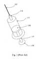
- FIG. 1is a perspective view of a prior art syringe used to inject drugs into the eye.
- the syringeincludes a needle 105 , a luer hub 110 , a chamber 115 , a plunger 120 , a plunger shaft 125 , and a thumb rest 130 .
- the drug to be injectedis located in chamber 115 . Pushing on the thumb rest 130 causes the plunger 120 to expel the drug through needle 105 .
- the surgeonis required to puncture the eye tissue with the needle, hold the syringe steady, and actuate the syringe plunger (with or without the help of a nurse) to inject the fluid into the eye.
- the volume injectedis typically not controlled in an accurate manner because the vernier on the syringe is not precise relative to the small injection volume. Fluid flow rates are uncontrolled. Reading the vernier is also subject to parallax error. Tissue damage may occur due to an “unsteady” injection. Reflux of the drug may also occur when the needle is removed from the eye.
- a commercially available fluid dispenseris the ULTRATM positive displacement dispenser available from EFD Inc. of Buffalo, R.I.
- the ULTRA dispenseris typically used in the dispensing of small volumes of industrial adhesives. It utilizes a conventional syringe and a custom dispensing tip. The syringe plunger is actuated using an electrical stepper motor and an actuating fluid.
- Parker Hannifin Corporation of Cleveland, Ohiodistributes a small volume liquid dispenser for drug discovery applications made by Aurora Instruments LLC of San Diego, Calif.
- the Parker/Aurora dispenserutilizes a piezo-electric dispensing mechanism.
- Ypsomed, Inc. of Switzerlandproduces a line of injection pens and automated injectors primarily for the self-injection of insulin or hormones by a patient. This product line includes simple disposable pens and electronically-controlled motorized injectors.
- U.S. Pat. No. 6,290,690discloses an ophthalmic system for injecting a viscous fluid (e.g. silicone oil) into the eye while simultaneously aspirating a second viscous fluid (e.g. perflourocarbon liquid) from the eye in a fluid/fluid exchange during surgery to repair a retinal detachment or tear.
- the systemincludes a conventional syringe with a plunger.
- One end of the syringeis fluidly coupled to a source of pneumatic pressure that provides a constant pneumatic pressure to actuate the plunger.
- the other end of the syringeis fluidly coupled to an infusion cannula via tubing to deliver the viscous fluid to be injected.
- the drugis to be heated or cooled, it is desirable to bring the drug to the proper temperature before it is injected into the eye and to keep it at the proper temperature during the course of the injection. For example, when a heated drug is used, it is desirable to keep the drug heated until it enters the eye. Accordingly, for optimal results, the drug should remain at an elevated temperature as it travels through then needle and into the eye.
- the present inventionis an injection device having a dispensing chamber housing, a plunger, and a temperature control device.
- the dispensing chamber housinghas a first part and a second part.
- the first partis thermally coupled to a needle.
- the second parthas an inner surface and an outer surface. The inner surface partially defines a dispensing chamber for holding a quantity of a substance.
- the second partis thermally coupled to the first part.
- the plungeris engaged with an inner surface of the dispensing chamber housing, is capable of sliding in the dispensing chamber housing, and is fluidly sealed to the inner surface of the dispensing chamber housing.
- the temperature control deviceat least partially surrounds the dispensing chamber housing and is capable of altering a temperature of the substance in the dispensing chamber.
- the second parthas a greater thermal coefficient than the first part.
- the present inventionis a dispensing chamber housing for an injection device.
- the housinghas a first part and a second part.
- the first partis thermally coupled to a needle.
- the second partis thermally coupled to the first part.
- the second parthas an inner surface and an outer surface. The inner surface partially defines a dispensing chamber for holding a quantity of a substance.
- the first partis less thermally conductive than the second part.
- the present inventionis an injection device having a dispensing chamber housing, a plunger, a temperature control device, a power source for providing power to the temperature control device, and a controller for controlling the temperature control device.
- the dispensing chamber housinghas a first part and a second part. The first part is thermally coupled to a needle.
- the second parthas an inner surface and an outer surface. The inner surface partially defines a dispensing chamber for holding a quantity of a substance.
- the second partis thermally coupled to the first part.
- the plungeris engaged with an inner surface of the dispensing chamber housing, is capable of sliding in the dispensing chamber housing, and is fluidly sealed to the inner surface of the dispensing chamber housing.
- the temperature control deviceat least partially surrounds the dispensing chamber housing and is capable of altering a temperature of the substance in the dispensing chamber.
- the second parthas a greater thermal coefficient than the first part.
- FIG. 1is a perspective view of a prior art syringe.
- FIG. 2is one view of an ophthalmic medical device including a disposable tip segment and a limited reuse assembly according to an embodiment of the present invention.
- FIG. 3is another embodiment of a limited reuse assembly according to the principles of the present invention.
- FIG. 4is a cross section view of a disposable tip segment and a limited reuse assembly according to an embodiment of the present invention.
- FIG. 5is an exploded cross section view of a tip segment for an ophthalmic medical device according to an embodiment of the present invention.
- FIGS. 6A and 6Bare exploded cross section views of a dual thermal coefficient dispensing chamber according to the principles of the present invention.
- FIG. 2is one view of an ophthalmic medical device including a disposable tip segment and a limited reuse assembly according to an embodiment of the present invention.
- the medical deviceincludes a tip segment 205 and a limited reuse assembly 250 .
- the tip segment 205includes a needle 210 , a housing 215 , and an optional light 275 .
- the limited reuse assembly 250includes a housing 255 , a switch 270 , a lock mechanism 265 , and a threaded portion 260 .
- Tip segment 205is capable of being connected to and removed from limited reuse assembly 250 .
- tip segment 205has a threaded portion on an interior surface of housing 215 that screws onto the threaded portion 260 of limited reuse assembly 250 .
- lock mechanism 265secures tip segment 215 to limited reuse assembly 250 .
- Lock mechanism 265may be in the form of a button, a sliding switch, or a cantilevered mechanism.
- Other mechanisms for connecting tip segment 205 to limited reuse assembly 250such as those involving structural features that mate with each other, are commonly known in the art and are within the scope of the present invention.
- Needle 210is adapted to deliver a substance, such as a drug, into an eye. Needle 210 may be of any commonly known configuration. Preferably, needle 210 is designed such that its thermal characteristics are conducive to the particular drug delivery application. For example, when a heated drug is to be delivered, needle 210 may be relatively short (several millimeters) in length to facilitate proper delivery of the drug.
- Switch 270is adapted to provide an input to the system.
- switch 270may be used to activate the system or to turn on a heater.
- Other switches, buttons, or user-directed control inputsare commonly known and may be employed with limited reuse assembly 250 and/or tip segment 205 .
- Optional light 275is illuminated when tip segment 205 is ready to be used.
- Optional light 275may protrude from housing 215 , or it may be contained within housing 215 , in which case, optional light 275 may be seen through a clear portion of housing 215 .
- optional light 275may be replaced by an indicator, such as a liquid crystal display, segmented display, or other device that indicates a status or condition of disposable tip segment 205 .
- optional light 275may also pulse on and off to indicate other states, such as, but not limited to a system error, fully charged battery, insufficiently charged battery or faulty connection between the tip segment 205 and limited use assembly 250 . While shown on tip segment 205 , optional light 275 or other indicator may be located on limited reuse assembly 250 .
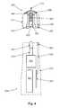
- FIG. 3is another embodiment of a limited reuse assembly according to the principles of the present invention.
- Limited reuse assembly 250includes a button 308 , a display 320 , and a housing 330 .
- Disposable tip segment 205attaches to end 340 of limited reuse assembly 250 .
- Button 308is actuated to provide an input to the system. As with switch 270 , button 308 may activate a heater or other temperature control device or initiate actuation of a plunger.
- Display 320is a liquid crystal display, segmented display, or other device that indicates a status or condition of disposable tip segment 205 or limited reuse assembly 250 .
- FIG. 4is cross section view of a disposable tip segment and a limited reuse assembly according to an embodiment of the present invention.
- FIG. 4shows how tip segment 205 interfaces with limited reuse assembly 250 .
- tip segment 205includes plunger interface 420 , plunger 415 , dispensing chamber housing 425 , tip segment housing 215 , temperature control device 450 , thermal sensor 460 , needle 210 , dispensing chamber 405 , interface 530 , and tip interface connector 453 .
- Limited reuse assembly 250includes mechanical linkage interface 545 , actuator shaft 510 , actuator 515 , power source 505 , controller 305 , limited reuse assembly housing 255 , interface 535 , and limited reuse assembly interface connector 553 .
- plunger interface 420is located on one end of plunger 415 .
- the other end of plunger 415forms one end of dispensing chamber 405 .
- Plunger 415is adapted to slide within dispensing chamber 405 .
- the outer surface of plunger 415is fluidly sealed to the inner surface of dispensing chamber housing 425 .
- Dispensing chamber housing 425surrounds the dispensing chamber 405 .
- dispensing chamber housing 425has a cylindrical shape.
- dispensing chamber 405also has a cylindrical shape.
- Dispensing chamber housing 425is made of two parts as described below.
- Needle 210is fluidly coupled to dispensing chamber 405 .
- a substance contained in dispensing chamber 405can pass through needle 210 and into an eye.
- Temperature control device 450at least partially surrounds dispensing chamber housing 425 .
- temperature control device 450is adapted to heat and/or cool dispensing chamber housing 425 and any substance contained in dispensing chamber 405 .
- Interface 530connects temperature control device 450 with tip interface connector 453 .
- Optional thermal sensor 460provides temperature information to assist in controlling the operation of temperature control device 450 .
- Thermal sensor 460may be located near dispensing chamber housing 425 and measure a temperature near dispensing chamber housing 425 or may be located in thermal contact with dispensing chamber housing 425 , in which case it measures a temperature of dispensing chamber housing 425 .
- Thermal sensor 460may be any of a number of different devices that can provide temperature information.
- thermal sensor 460may be a thermocouple or a resistive device whose resistance varies with temperature. Thermal sensor is also electrically coupled to interface 530 or other similar interface.
- tip segment 205The components of tip segment 205 , including dispensing chamber housing 425 , temperature control device 450 , and plunger 415 are at least partially enclosed by tip segment housing 215 .
- plunger 415is sealed to the interior surface of dispensing chamber housing 425 . This seal prevents contamination of any substance contained in dispensing chamber 405 . For medical purposes, such a seal is desirable. This seal can be located at any point on plunger 415 or dispensing chamber housing 425 .
- power source 505provides power to actuator 515 .
- An interface (not shown) between power source 505 and actuator 515serves as a conduit for providing power to actuator 515 .
- Actuator 515is connected to actuator shaft 510 .
- actuator shaft 510is integral with actuator 515 .
- Mechanical linkage interface 545is connected to actuator shaft 510 . In this configuration, as actuator 515 moves actuator shaft 510 upward toward needle 210 , mechanical linkage interface 545 also moves upward toward needle 210 .
- mechanical linkage interface 545 and actuator shaft 510are a single component.
- a shaft connected to actuator 515includes both actuator shaft 510 and mechanical linkage interface 545 as a single assembly.
- power source 505is typically a rechargeable battery, such as a lithium ion battery, although other types of batteries may be employed. In addition, any other type of power cell is appropriate for power source 505 .
- Power source 505provides current to dispensing chamber housing 425 to heat it and change its shape.
- power source 505can be removed from housing 255 through a door or other similar feature (not shown).
- Controller 305is connected via interface 535 to limited reuse assembly interface connecter 553 .
- Limited reuse assembly interface connecter 553is located on a top surface of limited reuse assembly housing 255 adjacent to mechanical linkage interface 545 . In this manner, both limited reuse assembly interface connector 553 and mechanical linkage interface 545 are adapted to be connected with tip interface connector 453 and plunger interface 420 , respectively.
- Controller 305 and actuator 515are connected by an interface (not shown). This interface (not shown) allows controller 305 to control the operation of actuator 515 .
- an interface between power source 505 and controller 305allows controller 305 to control operation of power source 505 . In such a case, controller 305 may control the charging and the discharging of power source 505 when power source 505 is a rechargeable battery.
- Controller 305is typically an integrated circuit with power, input, and output pins capable of performing logic functions.
- controller 305is a targeted device controller.
- controller 305performs specific control functions targeted to a specific device or component, such as a temperature control device or a power supply.
- a temperature control device controllerhas the basic functionality to control a temperature control device.
- controller 305is a microprocessor.
- controller 305is programmable so that it can function to control more than one component of the device.
- controller 305is not a programmable microprocessor, but instead is a special purpose controller configured to control different components that perform different functions. While depicted as one component in FIG. 5 , controller 305 may be made of many different components or integrated circuits.
- Tip segment 205is adapted to mate with or attach to limited reuse assembly 250 .
- plunger interface 420 located on a bottom surface of plunger 415is adapted to mate with mechanical linkage interface 545 located near a top surface of limited reuse assembly housing 255 .
- tip interface connector 453is adapted to connect with limited reuse assembly interface connector 553 .
- actuator 515 and actuator shaft 510are adapted to drive plunger 415 upward toward needle 210 .
- an interfaceis formed between controller 305 and temperature control device 450 . A signal can pass from controller 305 to temperature control device 450 through interface 535 , limited reuse assembly interface connector 553 , tip interface connector 453 , and interface 530 .
- controller 305controls the operation of actuator 515 .
- actuator 515When actuator 515 is actuated, actuator shaft 510 is moved upward toward needle 210 .
- mechanical linkage interface 545which is mated with plunger interface 420 , moves plunger 415 upward toward needle 210 .
- a substance located in dispensing chamber 405is then expelled through needle 210 .
- controller 305controls the operation of temperature control device 450 .
- Temperature control device 450is adapted to heat and/or cool dispensing chamber housing 425 and its contents. Since dispensing chamber housing 425 is at least partially thermally conductive, heating or cooling dispensing chamber housing 425 heats or cools a substance located in dispensing chamber 405 . Temperature information can be transferred from thermal sensor 460 through interface 530 , tip interface connector 453 , limited reuse assembly interface connector 553 , and interface 535 back to controller 305 . This temperature information can be used to control the operation of temperature control device 450 . When temperature control device 450 is a heater, controller 305 controls the amount of current that is sent to temperature control device 450 .
- controller 305can use a feed back loop utilizing information from thermal sensor 460 to control the operation of temperature control device 450 .
- Any suitable type of control algorithmsuch as a proportional integral derivative (PID) algorithm, can be used to control the operation of temperature control device 450 .
- PIDproportional integral derivative
- a substance to be delivered into an eyetypically a drug suspended in a phase transition compound, is located in dispensing chamber 405 .
- the drug and phase transition compoundare contacted by the inner surface of dispensing chamber housing 425 .
- the phase transition compoundis in a solid or semi-solid state at lower temperatures and in a more liquid state at higher temperatures.
- Such a compoundcan be heated by the application of current to temperature control device 450 to a more liquid state and injected into the eye where it forms a bolus that erodes over time.
- a reverse gelation compoundmay be used.
- a reverse gelation compoundis in a solid or semi-solid state at higher temperatures and in a more liquid state at lower temperatures.
- Such a compoundcan be cooled by temperature control device 450 to a more liquid state and injected into the eye where it forms a bolus that erodes over time.
- temperature control device 450may be a device that heats a substance in dispensing chamber 405 or a device that cools a substance in dispensing chamber 405 (or a combination of both).
- a phase transition compound or reverse gelation compounderodes over time providing a quantity of drug over an extended period of time. Using a phase transition compound or reverse gelation compound provides better drug dosage with fewer injections.
- the substance located in dispensing chamber 405is a drug that is preloaded into the dispensing chamber.
- tip segment 205is appropriate as a single use consumable product.
- Such a disposable productcan be assembled at a factory with a dosage of a drug installed.
- the injection system of FIG. 4may be a single piece device.
- the tip segmentis integrated into the limited reuse assembly to form a single medical device.
- FIG. 5is an exploded cross section view of a tip segment for an ophthalmic medical device according to an embodiment of the present invention.
- tip segment 205includes a dispensing chamber housing that has a first part 610 and a second part 620 , tip segment housing 215 , thermal sensor 460 , needle 210 , dispensing chamber 405 , plunger 415 , plunger interface 420 , temperature control device 450 , interface 530 , and tip interface connector 453 .
- temperature control device 450is activated to bring a substance in dispensing chamber 405 to within a proper temperature range.
- Thermal sensor 460provides temperature information to controller 305 (not shown) to control temperature control device 450 .
- plunger 415is actuated to deliver the substance through needle 210 and into an eye.
- the dispensing chamber housingis made of two components—a first part 610 and a second part 620 .
- first and second parts 610 , 620are generally cylindrical in shape and fit together to form a dispensing chamber housing capable of holding a substance.
- First part 610 and second part 620are made of different materials. Each of the two different materials has a different thermal coefficient (used herein to characterize a material's ability to conduct heat—also known as the thermal conductivity of a material).
- the first part 610has a lower thermal coefficient (and is capable of conducting less heat) than the second part 620 .
- the first part 610is thermally coupled to needle 210 (which is typically made of stainless steel).
- the second part 620primarily surrounds dispensing chamber 405 and the substance contained therein.
- thermal control device 450When thermal control device 450 is a heater or peltier, heat is applied to the first part 610 .
- First part 610conduct heat to second part 620 from thermal control device 450 .
- first part 610can be made to be hotter than second part 620 (at least for a period of time). Since first part 610 is thermally coupled to needle 210 , needle 210 is maintained at a temperature equal to or below first part 610 but higher than second part 620 . In this manner, thermal control device 450 can be used to heat a substance to a lower temperature range while keeping needle 210 at a higher temperature.
- heat from thermal control device 450is conducted by second part 620 to heat the substance contained in dispensing chamber 405 and is conducted by first part 610 to heat needle 210 .
- first part 610has a lower thermal coefficient than second part 620
- needle 210is kept at a higher temperature than the substance that is surrounded primarily by second part 620 . This allows for the injection substance to maintain its liquid state while being injected, while needle 210 is at a temperature which will prevent the substance from cooling too quickly.
- the lower thermal conductivity of needle 210prevents the tissue it has pierced from being adversely affected.
- temperature control device 450may be in thermal contact with both first part 610 and second part 620 or only with first part 610 . Since first part 610 is in thermal contact with second part 620 , heat may be conducted from first part 610 to second part 620 . Since second part 620 has a higher thermal conductivity than first part 610 , the heat transfer from first part 610 to second part 620 is limited, allowing for a temperature gradient ( 610 will have a higher temperature than 620 ) However, first part 610 will maintain its temperature more readily than second part 620 due to its lower thermal conductivity.
- phase transition compoundWhen the substance is a drug suspended in a phase transition compound, such an arrangement is beneficial. Keeping needle 210 at the same temperature or hotter than the phase-transition compound ensures that it will not cool too readily and clog needle 210 . Since a phase transition compound is heated to a liquid or semi-liquid state for injection into an eye, it should be maintained in that liquid or semi-liquid state until it enters the eye (where the eye acts like a heat sink and rapidly cools the phase transition compound to form a bolus that erodes over time). Keeping the needle at or above the temperature of the phase transition compound while it is in a liquid or semi-liquid state allows the phase transition compound to pass easily through needle 210 .
- needle 210were much cooler than the phase transition compound, then it would clog as the phase transition compound cools inside needle 210 .
- Utilizing a dispensing chamber housing made of first part 610 and second part 620 with different thermal coefficientsallows needle 210 to be maintained at a suitably heated temperature and allows the drug to be heated to an equal or lower temperature.
- needle 210is a small gauge needle (such as a 25 gauge needle). Such a small gauge needle cools if exposed to ambient air. As such first part 610 (with a lower thermal coefficient than second part 620 ) retains heat and keeps needle 210 at a suitably high temperature to facilitate injection of a phase transition compound into the eye.
- first part 610 and second part 620allows needle 210 to be kept cool when temperature control device 450 performs a cooling function.
- the lower thermal conductivity of needle 210prevents it from being readily heated by the tissue it comes in contact with.
- first part 610 and second part 620may both be metals (or alloys thereof) or non-metals or a combination of metals and non-metals.
- materialsinclude: Aluminum (205-237); Brass (109-159); Bronze (42-50); Copper (385-401); Gold (314-318); Silver (406-429); Stainless steel (14-16); Titanium (16-22); Titanium Alloy (5-6); Diamond (900-2320); Glass (0.8-1.4); and Polymers (0.3-0.5) where the thermal coefficient is a measure of thermal conductivity in watts per Kelvin meter. This list merely presents examples. Any number of different materials may be employed and are within the scope of this invention.
- first part 610is made of stainless steel and second part 620 is made of aluminum.
- FIGS. 6A and 6Bare exploded cross section views of a dual thermal coefficient dispensing chamber according to the principles of the present invention.
- first part 610is thermally connected to needle 210 .
- Second part 620primarily surrounds dispensing chamber 405 .
- First part 610 and second part 620are fitted together to form a liquid-tight seal for dispensing chamber 405 .
- First part 610has a lower thermal coefficient (and is less thermally conductive) than second part 620 .
- the present inventionprovides an improved system for delivering precise volumes of a substance.
- the present inventionprovides an injection device with a dispensing chamber housing made of two parts—each with a different thermal coefficient. This allows the needle to be maintained at a proper temperature for effective delivery of the drug.
- the present inventionis illustrated herein by example, and various modifications may be made by a person of ordinary skill in the art.
Landscapes
- Health & Medical Sciences (AREA)
- Life Sciences & Earth Sciences (AREA)
- General Health & Medical Sciences (AREA)
- Biomedical Technology (AREA)
- Heart & Thoracic Surgery (AREA)
- Vascular Medicine (AREA)
- Veterinary Medicine (AREA)
- Animal Behavior & Ethology (AREA)
- Engineering & Computer Science (AREA)
- Public Health (AREA)
- Anesthesiology (AREA)
- Hematology (AREA)
- Ophthalmology & Optometry (AREA)
- Infusion, Injection, And Reservoir Apparatuses (AREA)
- Dental Tools And Instruments Or Auxiliary Dental Instruments (AREA)
Abstract
Description
Claims (21)
Priority Applications (1)
| Application Number | Priority Date | Filing Date | Title |
|---|---|---|---|
| US11/777,408US8821440B2 (en) | 2006-05-17 | 2007-07-13 | Dual thermal coefficient dispensing chamber |
Applications Claiming Priority (3)
| Application Number | Priority Date | Filing Date | Title |
|---|---|---|---|
| US11/435,906US20070270750A1 (en) | 2006-05-17 | 2006-05-17 | Drug delivery device |
| US92149706P | 2006-10-16 | 2006-10-16 | |
| US11/777,408US8821440B2 (en) | 2006-05-17 | 2007-07-13 | Dual thermal coefficient dispensing chamber |
Related Parent Applications (1)
| Application Number | Title | Priority Date | Filing Date |
|---|---|---|---|
| US11/435,906Continuation-In-PartUS20070270750A1 (en) | 2006-05-17 | 2006-05-17 | Drug delivery device |
Publications (2)
| Publication Number | Publication Date |
|---|---|
| US20080015545A1 US20080015545A1 (en) | 2008-01-17 |
| US8821440B2true US8821440B2 (en) | 2014-09-02 |
Family
ID=38420664
Family Applications (7)
| Application Number | Title | Priority Date | Filing Date |
|---|---|---|---|
| US11/435,906AbandonedUS20070270750A1 (en) | 2006-05-17 | 2006-05-17 | Drug delivery device |
| US11/762,844Expired - Fee RelatedUS7762981B2 (en) | 2006-05-17 | 2007-06-14 | Temperature release mechanism for injection device |
| US11/777,408Expired - Fee RelatedUS8821440B2 (en) | 2006-05-17 | 2007-07-13 | Dual thermal coefficient dispensing chamber |
| US11/833,518AbandonedUS20080021419A1 (en) | 2006-05-17 | 2007-08-03 | Plunger Linkage Method For Ophthalmic Medical Device |
| US11/833,471AbandonedUS20080021412A1 (en) | 2006-05-17 | 2007-08-03 | Plunger Linkage and Seal For Ophthalmic Medical Device |
| US11/833,668Expired - Fee RelatedUS7887517B2 (en) | 2006-05-17 | 2007-08-03 | Drug casting |
| US12/109,079AbandonedUS20080197035A1 (en) | 2006-05-17 | 2008-04-24 | Sharps Container System for Two Piece Injection Device |
Family Applications Before (2)
| Application Number | Title | Priority Date | Filing Date |
|---|---|---|---|
| US11/435,906AbandonedUS20070270750A1 (en) | 2006-05-17 | 2006-05-17 | Drug delivery device |
| US11/762,844Expired - Fee RelatedUS7762981B2 (en) | 2006-05-17 | 2007-06-14 | Temperature release mechanism for injection device |
Family Applications After (4)
| Application Number | Title | Priority Date | Filing Date |
|---|---|---|---|
| US11/833,518AbandonedUS20080021419A1 (en) | 2006-05-17 | 2007-08-03 | Plunger Linkage Method For Ophthalmic Medical Device |
| US11/833,471AbandonedUS20080021412A1 (en) | 2006-05-17 | 2007-08-03 | Plunger Linkage and Seal For Ophthalmic Medical Device |
| US11/833,668Expired - Fee RelatedUS7887517B2 (en) | 2006-05-17 | 2007-08-03 | Drug casting |
| US12/109,079AbandonedUS20080197035A1 (en) | 2006-05-17 | 2008-04-24 | Sharps Container System for Two Piece Injection Device |
Country Status (12)
| Country | Link |
|---|---|
| US (7) | US20070270750A1 (en) |
| EP (1) | EP1857130A1 (en) |
| JP (1) | JP2007307376A (en) |
| KR (1) | KR20070111394A (en) |
| CN (1) | CN101073682A (en) |
| AR (1) | AR061002A1 (en) |
| AU (1) | AU2007202216A1 (en) |
| BR (1) | BRPI0702340A (en) |
| CA (1) | CA2588519A1 (en) |
| IL (1) | IL183295A0 (en) |
| MX (1) | MX2007005846A (en) |
| TW (1) | TW200744558A (en) |
Cited By (2)
| Publication number | Priority date | Publication date | Assignee | Title |
|---|---|---|---|---|
| USD821572S1 (en)* | 2016-06-20 | 2018-06-26 | Medimmune, Llc | Drug delivery implement with translucent housing |
| USD822199S1 (en)* | 2016-06-22 | 2018-07-03 | Medimmune, Llc | Drug delivery implement |
Families Citing this family (69)
| Publication number | Priority date | Publication date | Assignee | Title |
|---|---|---|---|---|
| US7431710B2 (en) | 2002-04-08 | 2008-10-07 | Glaukos Corporation | Ocular implants with anchors and methods thereof |
| US9486581B2 (en)* | 2002-09-11 | 2016-11-08 | Becton, Dickinson And Company | Injector device with force lock-out and injection rate limiting mechanisms |
| GB0418389D0 (en)* | 2004-08-18 | 2004-09-22 | Liversidge Barry P | Injection apparatus |
| US8361026B2 (en)* | 2005-02-01 | 2013-01-29 | Intelliject, Inc. | Apparatus and methods for self-administration of vaccines and other medicaments |
| US20070212397A1 (en)* | 2005-09-15 | 2007-09-13 | Roth Daniel B | Pharmaceutical delivery device and method for providing ocular treatment |
| US7887521B2 (en) | 2006-05-17 | 2011-02-15 | Alcon Research, Ltd. | Ophthalmic injection system |
| US7815603B2 (en)* | 2006-05-17 | 2010-10-19 | Alcon Research, Ltd. | Ophthalmic injection method |
| US20070270750A1 (en)* | 2006-05-17 | 2007-11-22 | Alcon, Inc. | Drug delivery device |
| US20080281292A1 (en)* | 2006-10-16 | 2008-11-13 | Hickingbotham Dyson W | Retractable Injection Port |
| US9022970B2 (en)* | 2006-10-16 | 2015-05-05 | Alcon Research, Ltd. | Ophthalmic injection device including dosage control device |
| US20090104945A1 (en)* | 2007-10-17 | 2009-04-23 | Sony Ericsson Mobile Communications Ab | handsfree cable for use with an electronic device |
| JP5330401B2 (en) | 2007-11-08 | 2013-10-30 | アリメラ・サイエンシーズ,インコーポレーテッド | Implant device for the eye and kit comprising the device |
| US20090227979A1 (en)* | 2008-03-07 | 2009-09-10 | Sanchez Jr Robert J | Drug Level Sensor for Injection Device |
| GB0805521D0 (en)* | 2008-03-27 | 2008-04-30 | The Technology Partnership Plc | Dispensing system |
| CN101574550B (en)* | 2008-05-06 | 2013-02-13 | 德昌电机(深圳)有限公司 | Injection device |
| US8623395B2 (en) | 2010-01-29 | 2014-01-07 | Forsight Vision4, Inc. | Implantable therapeutic device |
| CN104887389B (en) | 2009-01-29 | 2017-06-23 | 弗赛特影像4股份有限公司 | Posterior segment drug delivery |
| US8372036B2 (en) | 2009-05-06 | 2013-02-12 | Alcon Research, Ltd. | Multi-layer heat assembly for a drug delivery device |
| WO2012071476A2 (en) | 2010-11-24 | 2012-05-31 | David Haffner | Drug eluting ocular implant |
| WO2010135369A1 (en) | 2009-05-18 | 2010-11-25 | Dose Medical Corporation | Drug eluting ocular implant |
| US10206813B2 (en) | 2009-05-18 | 2019-02-19 | Dose Medical Corporation | Implants with controlled drug delivery features and methods of using same |
| US8177747B2 (en) | 2009-12-22 | 2012-05-15 | Alcon Research, Ltd. | Method and apparatus for drug delivery |
| US10166142B2 (en) | 2010-01-29 | 2019-01-01 | Forsight Vision4, Inc. | Small molecule delivery with implantable therapeutic device |
| CA2736841C (en) | 2010-04-15 | 2014-02-18 | Teneo Innovations Inc. | Device and electronic controller for syringe piston control |
| LT2600930T (en) | 2010-08-05 | 2021-04-12 | Forsight Vision4, Inc. | Injector apparatus for drug delivery |
| US10617557B2 (en) | 2010-08-05 | 2020-04-14 | Forsight Vision4, Inc. | Combined drug delivery methods and apparatus |
| PT2600812T (en) | 2010-08-05 | 2021-11-09 | Forsight Vision4 Inc | Implantable therapeutic device |
| WO2012068549A2 (en) | 2010-11-19 | 2012-05-24 | Forsight Vision4, Inc. | Therapeutic agent formulations for implanted devices |
| KR101092074B1 (en)* | 2011-02-22 | 2011-12-12 | 문창수 | Anesthetic syringe |
| JP6038124B2 (en)* | 2011-05-06 | 2016-12-07 | サノフィ−アベンティス・ドイチュラント・ゲゼルシャフト・ミット・ベシュレンクテル・ハフツング | Lockout members with different cross sections |
| GB2490721B (en)* | 2011-05-12 | 2017-03-01 | Owen Mumford Ltd | Injection devices |
| US10245178B1 (en) | 2011-06-07 | 2019-04-02 | Glaukos Corporation | Anterior chamber drug-eluting ocular implant |
| US10398592B2 (en) | 2011-06-28 | 2019-09-03 | Forsight Vision4, Inc. | Diagnostic methods and apparatus |
| US20130053816A1 (en)* | 2011-07-25 | 2013-02-28 | Tandem Diabetes Care, Inc. | Multi-reservoir infusion pump systems and methods |
| HRP20210676T1 (en) | 2011-09-16 | 2021-05-28 | Forsight Vision4, Inc. | Fluid exchange apparatus |
| US9180242B2 (en) | 2012-05-17 | 2015-11-10 | Tandem Diabetes Care, Inc. | Methods and devices for multiple fluid transfer |
| GB2526948A (en) | 2012-12-27 | 2015-12-09 | Kaleo Inc | Systems for locating and interacting with medicament delivery devices |
| US9173998B2 (en) | 2013-03-14 | 2015-11-03 | Tandem Diabetes Care, Inc. | System and method for detecting occlusions in an infusion pump |
| WO2014152959A1 (en) | 2013-03-14 | 2014-09-25 | Forsight Vision4, Inc. | Systems for sustained intraocular delivery of low solubility compounds from a port delivery system implant |
| ES2972168T3 (en) | 2013-03-28 | 2024-06-11 | Forsight Vision4 Inc | Ophthalmic implant for administration of therapeutic substances |
| EP2810675A1 (en)* | 2013-06-04 | 2014-12-10 | Bioftalmik, S.L. | Injector for intraocular injection |
| EP3677229A1 (en) | 2014-05-29 | 2020-07-08 | Glaukos Corporation | Implants with controlled drug delivery features |
| WO2016022750A1 (en) | 2014-08-08 | 2016-02-11 | Forsight Vision4, Inc. | Stable and soluble formulations of receptor tyrosine kinase inhibitors, and methods of preparation thereof |
| MX2017006267A (en) | 2014-11-18 | 2017-08-14 | Lilly Co Eli | Thermal locking mechanism for a medication delivery device. |
| KR101789703B1 (en)* | 2015-06-12 | 2017-10-25 | 서울대학교산학협력단 | Biosensor and method for forming the same |
| WO2016200104A1 (en)* | 2015-06-12 | 2016-12-15 | 서울대학교산학협력단 | Biosensor and method for forming same and glucose control system, method for forming the glucose control system, and method for controlling glucose thereby |
| US10279107B2 (en) | 2015-08-20 | 2019-05-07 | Tandem Diabetes Care, Inc. | Drive mechanism for infusion pump |
| JP6456550B2 (en) | 2015-09-01 | 2019-01-23 | コーニンクレッカ フィリップス エヌ ヴェKoninklijke Philips N.V. | Device for displaying medical image data of a body part |
| US11925578B2 (en) | 2015-09-02 | 2024-03-12 | Glaukos Corporation | Drug delivery implants with bi-directional delivery capacity |
| US10182939B2 (en) | 2015-09-16 | 2019-01-22 | Novartis Ag | Hydraulic injector and methods for intra-ocular lens insertion |
| US11564833B2 (en) | 2015-09-25 | 2023-01-31 | Glaukos Corporation | Punctal implants with controlled drug delivery features and methods of using same |
| US11432959B2 (en) | 2015-11-20 | 2022-09-06 | Forsight Vision4, Inc. | Porous structures for extended release drug delivery devices |
| EP3380173A1 (en)* | 2015-11-27 | 2018-10-03 | Sanofi-Aventis Deutschland GmbH | An injection device with protective cap allowing electromagnetic field induction |
| US10946141B2 (en)* | 2016-03-14 | 2021-03-16 | Virchow Biotech Pvt. Ltd. | Sterile protective cover comprising a device for opthalmic delivery |
| CN109937025B (en) | 2016-04-20 | 2022-07-29 | 多斯医学公司 | Delivery device for bioabsorbable ocular drugs |
| CA3046354A1 (en) | 2017-01-17 | 2018-07-26 | Kaleo, Inc. | Medicament delivery devices with wireless connectivity and event detection |
| BR112020004978A2 (en)* | 2017-09-15 | 2020-09-15 | Oxular Limited | sterile lyophilized pharmacological composition, pharmaceutical formulation, unit dosage form, kit, method for treating an eye disease or condition, method for treating an eye disease or condition and pharmacological composition, pharmacological composition for use |
| AU2018372806B2 (en) | 2017-11-21 | 2024-05-30 | Forsight Vision4, Inc. | Fluid exchange apparatus for expandable port delivery system and methods of use |
| CN111936182B (en) | 2018-02-05 | 2022-08-23 | 坦德姆糖尿病护理股份有限公司 | Method and system for detecting the condition of an infusion pump |
| US11929160B2 (en) | 2018-07-16 | 2024-03-12 | Kaleo, Inc. | Medicament delivery devices with wireless connectivity and compliance detection |
| CN111956905A (en)* | 2020-07-23 | 2020-11-20 | 中国人民解放军空军军医大学 | Local injection device for hypertrophic scar |
| USD1033637S1 (en) | 2022-01-24 | 2024-07-02 | Forsight Vision4, Inc. | Fluid exchange device |
| US12337160B1 (en) | 2024-04-19 | 2025-06-24 | Genzyme Corporation | Medicament delivery device |
| US12343505B1 (en) | 2024-04-19 | 2025-07-01 | Genzyme Corporation | Medicament delivery device |
| US12357758B1 (en)* | 2024-04-19 | 2025-07-15 | Genzyme Corporation | Medicament delivery device |
| US12377226B1 (en) | 2024-04-19 | 2025-08-05 | Genzyme Corporation | Medicament delivery device |
| US12343511B1 (en) | 2024-04-19 | 2025-07-01 | Genzyme Corporation | Medicament delivery device |
| US12420017B1 (en) | 2025-02-26 | 2025-09-23 | Genzyme Corporation | Damping device for a medicament delivery device |
| US12434008B1 (en) | 2025-02-26 | 2025-10-07 | Genzyme Corporation | Lock ring for a medicament delivery device |
Citations (74)
| Publication number | Priority date | Publication date | Assignee | Title |
|---|---|---|---|---|
| US1252614A (en) | 1917-04-24 | 1918-01-08 | Oscar H Pieper | Hot-air syringe. |
| US3089815A (en) | 1951-10-11 | 1963-05-14 | Lieb Hans | Injectable pharmaceutical preparation, and a method of making same |
| US3608549A (en) | 1970-01-15 | 1971-09-28 | Merrill Edward Wilson | Method of administering drugs and capsule therefor |
| US3892537A (en) | 1973-11-28 | 1975-07-01 | Corning Glass Works | Preload means for ceramic substrate in exhaust gas purifiers |
| US3982537A (en) | 1974-12-30 | 1976-09-28 | Louis Bucalo | Dynamic implants and method for implanting the same |
| US4007742A (en) | 1974-06-03 | 1977-02-15 | Surgical Design Corporation. | Surgical system for controlling the infusion of fluid to and the evacuation of fluid and material from an operating field |
| US4030499A (en) | 1974-12-30 | 1977-06-21 | Louis Bucalo | Method and apparatus for providing living beings with absorbable implants |
| US4054138A (en) | 1974-12-30 | 1977-10-18 | Louis Bucalo | Implants for acting on living beings |
| US4122850A (en) | 1976-06-07 | 1978-10-31 | Louis Bucalo | Apparatus for providing living beings with absorbable implants |
| GB1551767A (en) | 1975-05-27 | 1979-08-30 | Bucalo L | Implantment of living beings or the like subjects |
| US4184510A (en) | 1977-03-15 | 1980-01-22 | Fibra-Sonics, Inc. | Valued device for controlling vacuum in surgery |
| US4246932A (en) | 1979-10-18 | 1981-01-27 | Burron Medical, Inc. | Multiple additive valve assembly |
| US4265618A (en)* | 1977-09-09 | 1981-05-05 | Solar Energy Technology, Inc. | Electrically heated endodontic syringe for injecting thermoplastic material into a root canal cavity |
| US4357136A (en) | 1977-09-09 | 1982-11-02 | Solar Energy Technology, Inc. | Method for filling a root canal |
| WO1982003761A1 (en) | 1981-05-04 | 1982-11-11 | Energy Techn Inc Solar | Syringe for obturation of root canal cavities |
| US4392827A (en) | 1981-11-04 | 1983-07-12 | Howard Martin | Self-contained root canal heated condenser dental instrument |
| US4474752A (en) | 1983-05-16 | 1984-10-02 | Merck & Co., Inc. | Drug delivery system utilizing thermosetting gels |
| US4484915A (en) | 1983-03-28 | 1984-11-27 | Tartaglia John A | Medical syringe |
| US4582488A (en)* | 1984-04-27 | 1986-04-15 | Newman Martin H | Dental materials dispenser and applicator |
| WO1987000029A1 (en) | 1985-06-26 | 1987-01-15 | Pitz Richard J | Root canal implant-proximity indicative-delivery means |
| US4684344A (en) | 1986-04-11 | 1987-08-04 | Nalge Company | Electrically powered and heated endodontic syringe |
| US4704088A (en) | 1984-04-27 | 1987-11-03 | Newman Martin H | Dental materials dispenser and applicator |
| US4713446A (en) | 1985-09-06 | 1987-12-15 | Minnesota Mining And Manufacturing Company | Viscoelastic collagen solution for ophthalmic use and method of preparation |
| US4795423A (en) | 1980-04-14 | 1989-01-03 | Thomas Jefferson University | Oxygenated perfluorinated perfusion of the ocular globe to treat ischemic retinopathy |
| US4830855A (en) | 1987-11-13 | 1989-05-16 | Landec Labs, Inc. | Temperature-controlled active agent dispenser |
| EP0348146A1 (en) | 1988-06-21 | 1989-12-27 | Alcon Laboratories, Inc. | Apparatus for injecting viscous fluid into the eye |
| EP0398394A2 (en) | 1983-11-15 | 1990-11-22 | KAMEN, Dean L. | Reservoir assembly for removable engagement with a motor drive |
| US4992045A (en) | 1987-04-01 | 1991-02-12 | Dentsply Research & Development Corp. | Battery powered condenser for root canals |
| US5120307A (en) | 1988-06-21 | 1992-06-09 | Alcon Laboratories, Inc. | Method for injecting viscous fluid into the eye to life retinal membrane |
| US5336175A (en) | 1992-10-29 | 1994-08-09 | Mames Robert N | Method for the treatment of retinal detachments |
| US5360413A (en) | 1991-12-06 | 1994-11-01 | Filtertek, Inc. | Needleless access device |
| US5370630A (en) | 1993-11-12 | 1994-12-06 | Smidebush; Michael J. | Device for injection of fluidic materials into body tissue |
| US5476511A (en) | 1992-05-04 | 1995-12-19 | Allergan, Inc. | Subconjunctival implants for ocular drug delivery |
| US5487725A (en) | 1994-05-12 | 1996-01-30 | Syntec, Inc. | Pneumatic vitrectomy for retinal attachment |
| WO1996003978A1 (en) | 1994-08-04 | 1996-02-15 | Quadrant Holdings Cambridge Limited | Solid delivery systems for controlled release of molecules incorporated therein and methods of making same |
| US5582595A (en) | 1995-09-28 | 1996-12-10 | Habley Medical Technology Corporation | Aspirating syringe having a plunger guide for a reciprocating plunger assembly |
| US5620700A (en) | 1990-10-30 | 1997-04-15 | Alza Corporation | Injectable drug delivery system and method |
| US5743886A (en) | 1994-02-15 | 1998-04-28 | Lawrence A. Lynn | Sequential medical fluid aspiration and injection system and method |
| US5773019A (en) | 1995-09-27 | 1998-06-30 | The University Of Kentucky Research Foundation | Implantable controlled release device to deliver drugs directly to an internal portion of the body |
| US5783205A (en) | 1990-10-30 | 1998-07-21 | Alza Corporation | Injectable drug delivery system and method |
| US5824072A (en) | 1993-11-15 | 1998-10-20 | Oculex Pharmaceuticals, Inc. | Biocompatible ocular implants |
| US5860949A (en) | 1996-12-20 | 1999-01-19 | Chen; Jen-Yie | Volume homeostatic fluid-fluid exchanger |
| WO1999033853A2 (en) | 1997-12-23 | 1999-07-08 | Quadrant Holdings Cambridge Limited | Carbohydrates, useful in solid delivery systems |
| US5928663A (en) | 1997-07-30 | 1999-07-27 | Vitrophage, Inc. | Intraocular perfluorcarbon compositions and surgical methods of using same |
| US5984889A (en) | 1996-02-23 | 1999-11-16 | Allergan Sales, Inc. | Apparatus and method for delivering viscoelastic material to an eye |
| WO2001010482A1 (en) | 1999-08-05 | 2001-02-15 | Biocardia, Inc. | A system and method for delivering thermally sensitive and reverse-thermal gelation matrials |
| US6210357B1 (en) | 1998-07-06 | 2001-04-03 | Robert E Morris | Apparatus for performing surgery inside the human retina using fluidic internal limiting membrane (ILM) separation (films) |
| US6270343B1 (en) | 2000-01-07 | 2001-08-07 | Howard Martin | Endodontic thermal condenser dental instrument |
| US6290690B1 (en) | 1999-06-21 | 2001-09-18 | Alcon Manufacturing, Ltd. | Simultaneous injection and aspiration of viscous fluids in a surgical system |
| US6364865B1 (en) | 1998-11-13 | 2002-04-02 | Elan Pharma International Limited | Drug delivery systems and methods |
| US6372245B1 (en) | 1992-12-29 | 2002-04-16 | Insite Vision Incorporated | Plasticized bioerodible controlled delivery system |
| US20020055720A1 (en) | 2000-05-18 | 2002-05-09 | Dentsply Research & Development Corp. | Fluid material dispensing syringe |
| US6413245B1 (en) | 1999-10-21 | 2002-07-02 | Alcon Universal Ltd. | Sub-tenon drug delivery |
| US6419656B1 (en) | 1999-03-19 | 2002-07-16 | Arzneimittel Gmbh Apotheker Vetter & Ravensburg | Medical syringe with braked step-advance plunger |
| US6436143B1 (en) | 1999-02-22 | 2002-08-20 | Anthony C. Ross | Method and apparatus for treating intervertebral disks |
| US6520930B2 (en) | 1999-11-24 | 2003-02-18 | Medrad, Inc. | Injectors, injector systems and injector control |
| US20030055380A1 (en) | 2001-09-19 | 2003-03-20 | Flaherty J. Christopher | Plunger for patient infusion device |
| US6585700B1 (en) | 2000-10-05 | 2003-07-01 | Medrad, Inc. | Syringe, syringe plunger and attachment mechanism for front loading medical injector |
| US6595979B1 (en) | 2001-07-10 | 2003-07-22 | Myocardial Therapeutics, Inc. | Methods for sterile aspiration/reinjection of bodily fluid |
| US6635267B1 (en) | 1998-11-10 | 2003-10-21 | Denki Kagaku Kogyo Kabushiki Kaisha | Hyaluronic acid gel, process for the preparation thereof and medical materials containing the same |
| US6645179B1 (en) | 1999-07-06 | 2003-11-11 | Nihon Chemical Research Co., Ltd. | Injection syringe |
| US20040039253A1 (en) | 2002-08-20 | 2004-02-26 | Peyman Gholam A. | Treatment of retinal detachment |
| US20040052761A1 (en) | 2002-07-19 | 2004-03-18 | Brent Vernon | Localized delivery system for cancer drugs, phenstatin, using N-isopropylacrylamide |
| US20040133155A1 (en) | 2000-08-30 | 2004-07-08 | Varner Sign Erickson | Devices for intraocular drug delivery |
| US20040176720A1 (en) | 2002-08-31 | 2004-09-09 | Urs Kipfer | Device for administering a liquid solution of an active substance |
| US20040210200A1 (en) | 2003-04-16 | 2004-10-21 | Gerondale Scott J. | Controlled volume injection/aspiration device |
| US20040231667A1 (en) | 2001-06-11 | 2004-11-25 | Horton Andrew Paul | Medicament dispenser |
| US20050065477A1 (en) | 2003-09-19 | 2005-03-24 | Stefan Jost | Device for dispensing an injectable product in doses |
| US20050177137A1 (en) | 2002-08-31 | 2005-08-11 | Urs Kipfer | Administering device with temperature sensor |
| US20050186532A1 (en)* | 2004-02-20 | 2005-08-25 | Joshua Friedman | Heated compule |
| US6940209B2 (en) | 2003-09-08 | 2005-09-06 | New Scale Technologies | Ultrasonic lead screw motor |
| US6991457B2 (en)* | 2003-05-06 | 2006-01-31 | Aseptico, Inc. | Endodontic obturator with disposable cartridge |
| WO2006050008A1 (en) | 2003-06-20 | 2006-05-11 | Allergan, Inc. | Needleless applicator system and method for application of medicament to the back of an eye |
| US7176030B2 (en) | 2002-06-17 | 2007-02-13 | O.R. Solutions, Inc. | Method and apparatus for ensuring sterility of disposable medical items used with medical equipment |
Family Cites Families (42)
| Publication number | Priority date | Publication date | Assignee | Title |
|---|---|---|---|---|
| US176720A (en)* | 1876-04-25 | Improvement in processes for preserving eggs | ||
| US39253A (en)* | 1863-07-14 | Improved hinged collar for lamps | ||
| US210200A (en)* | 1878-11-26 | Improvement in machines for cutting escutcheons | ||
| US125665A (en)* | 1872-04-16 | Improvement in brakes for railway cars | ||
| US177137A (en)* | 1876-05-09 | Improvement in devices for starting pendulum-clocks | ||
| US47250A (en)* | 1865-04-11 | carteb | ||
| US133155A (en)* | 1872-11-19 | Improvement in portable cooking apparatus | ||
| US52761A (en)* | 1866-02-20 | Improvement in telegraph-insulators | ||
| US3466752A (en)* | 1967-08-14 | 1969-09-16 | Gilles G Braun | Heater stand and cavity injector |
| GB1175650A (en)* | 1968-11-07 | 1969-12-23 | Standard Telephones Cables Ltd | Adhesive Applicator |
| US3858581A (en)* | 1973-07-02 | 1975-01-07 | Dean Kamen | Medication injection device |
| US4648872A (en)* | 1983-11-15 | 1987-03-10 | Kamen Dean L | Volumetric pump with replaceable reservoir assembly |
| US5242391A (en)* | 1990-04-25 | 1993-09-07 | Alza Corporation | Urethral insert for treatment of erectile dysfunction |
| US5127522A (en)* | 1990-08-02 | 1992-07-07 | Sherwood Medical Company | Sharps container with notched insert |
| US5170779A (en)* | 1991-01-22 | 1992-12-15 | Ginsberg Irwin A | Automated ear cleansing device |
| US5368582A (en)* | 1992-08-10 | 1994-11-29 | The Schepens Eye Research Institute | Method and apparatus for introducing fluid material into an eye |
| US5882338A (en)* | 1993-05-04 | 1999-03-16 | Zeneca Limited | Syringes and syringe pumps |
| US6221045B1 (en)* | 1995-04-20 | 2001-04-24 | Acist Medical Systems, Inc. | Angiographic injector system with automatic high/low pressure switching |
| FR2734485B1 (en) | 1995-05-24 | 1997-10-10 | Biodome | PRE-FILLED SAFETY SYRINGE |
| US5891094A (en)* | 1995-09-07 | 1999-04-06 | Innerdyne, Inc. | System for direct heating of fluid solution in a hollow body organ and methods |
| US5868710A (en)* | 1996-11-22 | 1999-02-09 | Liebel Flarsheim Company | Medical fluid injector |
| US6139571A (en)* | 1997-07-09 | 2000-10-31 | Fuller Research Corporation | Heated fluid surgical instrument |
| US6079765A (en) | 1997-10-27 | 2000-06-27 | Lear Automotive Dearborn, Inc. | Wire holding clip for trim panel |
| WO1999049818A1 (en)* | 1998-03-30 | 1999-10-07 | Marchosky J Alexander | Prosthetic system |
| JP2002518108A (en)* | 1998-06-15 | 2002-06-25 | メドラッド インコーポレイテッド | Encoding syringe information |
| US6372246B1 (en)* | 1998-12-16 | 2002-04-16 | Ortho-Mcneil Pharmaceutical, Inc. | Polyethylene glycol coating for electrostatic dry deposition of pharmaceuticals |
| US6375638B2 (en)* | 1999-02-12 | 2002-04-23 | Medtronic Minimed, Inc. | Incremental motion pump mechanisms powered by shape memory alloy wire or the like |
| EP1315533A4 (en)* | 2000-08-15 | 2007-06-27 | Univ Kentucky Res Found | Programmable multi-dose intranasal drug delivery device |
| US6691977B2 (en)* | 2001-03-16 | 2004-02-17 | Delphi Technologies, Inc. | Shape memory alloy fuel injector |
| WO2003024503A2 (en)* | 2001-09-17 | 2003-03-27 | Durect Corporation | Device and method for accurate delivery of an active agent |
| US7086861B2 (en)* | 2002-03-01 | 2006-08-08 | Pitz Richard J | System for dispensing viscous materials |
| US7052251B2 (en)* | 2002-04-22 | 2006-05-30 | Medtronic Minimed, Inc. | Shape memory alloy wire driven positive displacement micropump with pulsatile output |
| US6960192B1 (en)* | 2002-04-23 | 2005-11-01 | Insulet Corporation | Transcutaneous fluid delivery system |
| US6929619B2 (en)* | 2002-08-02 | 2005-08-16 | Liebel-Flarshiem Company | Injector |
| US7128727B2 (en)* | 2002-09-30 | 2006-10-31 | Flaherty J Christopher | Components and methods for patient infusion device |
| US7186247B2 (en)* | 2003-04-04 | 2007-03-06 | Medtronic, Inc. | Apparatus and system for delivery of drug therapies |
| US20040267202A1 (en)* | 2003-06-26 | 2004-12-30 | Potter Daniel J. | Tearable hemostasis valve and splittable sheath |
| US20060047250A1 (en) | 2004-08-30 | 2006-03-02 | Hickingbotham Dyson W | Fluid delivery device |
| US7507221B2 (en) | 2004-10-13 | 2009-03-24 | Mallinckrodt Inc. | Powerhead of a power injection system |
| US20070038174A1 (en)* | 2005-08-09 | 2007-02-15 | Hopkins Mark A | Ophthalmic injector system |
| US20070060887A1 (en)* | 2005-08-22 | 2007-03-15 | Marsh David A | Ophthalmic injector |
| US20070270750A1 (en)* | 2006-05-17 | 2007-11-22 | Alcon, Inc. | Drug delivery device |
- 2006
- 2006-05-17USUS11/435,906patent/US20070270750A1/ennot_activeAbandoned
- 2007
- 2007-05-15EPEP07108293Apatent/EP1857130A1/ennot_activeCeased
- 2007-05-15CACA002588519Apatent/CA2588519A1/ennot_activeAbandoned
- 2007-05-16MXMX2007005846Apatent/MX2007005846A/ennot_activeApplication Discontinuation
- 2007-05-16TWTW096117365Apatent/TW200744558A/enunknown
- 2007-05-16BRBRPI0702340-5Apatent/BRPI0702340A/ennot_activeIP Right Cessation
- 2007-05-17ARARP070102129Apatent/AR061002A1/enunknown
- 2007-05-17CNCNA200710104927XApatent/CN101073682A/enactivePending
- 2007-05-17KRKR1020070048065Apatent/KR20070111394A/ennot_activeCeased
- 2007-05-17JPJP2007131544Apatent/JP2007307376A/enactivePending
- 2007-05-17ILIL183295Apatent/IL183295A0/enunknown
- 2007-05-17AUAU2007202216Apatent/AU2007202216A1/ennot_activeAbandoned
- 2007-06-14USUS11/762,844patent/US7762981B2/ennot_activeExpired - Fee Related
- 2007-07-13USUS11/777,408patent/US8821440B2/ennot_activeExpired - Fee Related
- 2007-08-03USUS11/833,518patent/US20080021419A1/ennot_activeAbandoned
- 2007-08-03USUS11/833,471patent/US20080021412A1/ennot_activeAbandoned
- 2007-08-03USUS11/833,668patent/US7887517B2/ennot_activeExpired - Fee Related
- 2008
- 2008-04-24USUS12/109,079patent/US20080197035A1/ennot_activeAbandoned
Patent Citations (79)
| Publication number | Priority date | Publication date | Assignee | Title |
|---|---|---|---|---|
| US1252614A (en) | 1917-04-24 | 1918-01-08 | Oscar H Pieper | Hot-air syringe. |
| US3089815A (en) | 1951-10-11 | 1963-05-14 | Lieb Hans | Injectable pharmaceutical preparation, and a method of making same |
| US3608549A (en) | 1970-01-15 | 1971-09-28 | Merrill Edward Wilson | Method of administering drugs and capsule therefor |
| US3892537A (en) | 1973-11-28 | 1975-07-01 | Corning Glass Works | Preload means for ceramic substrate in exhaust gas purifiers |
| US4007742A (en) | 1974-06-03 | 1977-02-15 | Surgical Design Corporation. | Surgical system for controlling the infusion of fluid to and the evacuation of fluid and material from an operating field |
| US3982537A (en) | 1974-12-30 | 1976-09-28 | Louis Bucalo | Dynamic implants and method for implanting the same |
| US4030499A (en) | 1974-12-30 | 1977-06-21 | Louis Bucalo | Method and apparatus for providing living beings with absorbable implants |
| US4054138A (en) | 1974-12-30 | 1977-10-18 | Louis Bucalo | Implants for acting on living beings |
| GB1551767A (en) | 1975-05-27 | 1979-08-30 | Bucalo L | Implantment of living beings or the like subjects |
| US4122850A (en) | 1976-06-07 | 1978-10-31 | Louis Bucalo | Apparatus for providing living beings with absorbable implants |
| US4184510A (en) | 1977-03-15 | 1980-01-22 | Fibra-Sonics, Inc. | Valued device for controlling vacuum in surgery |
| US4265618A (en)* | 1977-09-09 | 1981-05-05 | Solar Energy Technology, Inc. | Electrically heated endodontic syringe for injecting thermoplastic material into a root canal cavity |
| US4357136A (en) | 1977-09-09 | 1982-11-02 | Solar Energy Technology, Inc. | Method for filling a root canal |
| US4246932A (en) | 1979-10-18 | 1981-01-27 | Burron Medical, Inc. | Multiple additive valve assembly |
| US4795423A (en) | 1980-04-14 | 1989-01-03 | Thomas Jefferson University | Oxygenated perfluorinated perfusion of the ocular globe to treat ischemic retinopathy |
| WO1982003761A1 (en) | 1981-05-04 | 1982-11-11 | Energy Techn Inc Solar | Syringe for obturation of root canal cavities |
| US4392827A (en) | 1981-11-04 | 1983-07-12 | Howard Martin | Self-contained root canal heated condenser dental instrument |
| US4484915A (en) | 1983-03-28 | 1984-11-27 | Tartaglia John A | Medical syringe |
| US4474752A (en) | 1983-05-16 | 1984-10-02 | Merck & Co., Inc. | Drug delivery system utilizing thermosetting gels |
| EP0398394A2 (en) | 1983-11-15 | 1990-11-22 | KAMEN, Dean L. | Reservoir assembly for removable engagement with a motor drive |
| US4582488A (en)* | 1984-04-27 | 1986-04-15 | Newman Martin H | Dental materials dispenser and applicator |
| US4704088A (en) | 1984-04-27 | 1987-11-03 | Newman Martin H | Dental materials dispenser and applicator |
| WO1987000029A1 (en) | 1985-06-26 | 1987-01-15 | Pitz Richard J | Root canal implant-proximity indicative-delivery means |
| US4713446A (en) | 1985-09-06 | 1987-12-15 | Minnesota Mining And Manufacturing Company | Viscoelastic collagen solution for ophthalmic use and method of preparation |
| US4684344A (en) | 1986-04-11 | 1987-08-04 | Nalge Company | Electrically powered and heated endodontic syringe |
| US4992045A (en) | 1987-04-01 | 1991-02-12 | Dentsply Research & Development Corp. | Battery powered condenser for root canals |
| US4830855A (en) | 1987-11-13 | 1989-05-16 | Landec Labs, Inc. | Temperature-controlled active agent dispenser |
| US5120307A (en) | 1988-06-21 | 1992-06-09 | Alcon Laboratories, Inc. | Method for injecting viscous fluid into the eye to life retinal membrane |
| US5066276A (en) | 1988-06-21 | 1991-11-19 | Alcon Laboratories, Inc. | Method and apparatus for injecting viscous fluid into the eye to lift pre-retinal and post-retinal membrane with linear pressure control |
| EP0348146A1 (en) | 1988-06-21 | 1989-12-27 | Alcon Laboratories, Inc. | Apparatus for injecting viscous fluid into the eye |
| US5328481A (en) | 1988-06-21 | 1994-07-12 | Alcon Laboratories, Inc. | Method for injecting viscous fluid into the eye to lift retinal membrane |
| US5783205A (en) | 1990-10-30 | 1998-07-21 | Alza Corporation | Injectable drug delivery system and method |
| US5620700A (en) | 1990-10-30 | 1997-04-15 | Alza Corporation | Injectable drug delivery system and method |
| US5360413A (en) | 1991-12-06 | 1994-11-01 | Filtertek, Inc. | Needleless access device |
| US5476511A (en) | 1992-05-04 | 1995-12-19 | Allergan, Inc. | Subconjunctival implants for ocular drug delivery |
| US5336175A (en) | 1992-10-29 | 1994-08-09 | Mames Robert N | Method for the treatment of retinal detachments |
| US6372245B1 (en) | 1992-12-29 | 2002-04-16 | Insite Vision Incorporated | Plasticized bioerodible controlled delivery system |
| US5370630A (en) | 1993-11-12 | 1994-12-06 | Smidebush; Michael J. | Device for injection of fluidic materials into body tissue |
| US5824072A (en) | 1993-11-15 | 1998-10-20 | Oculex Pharmaceuticals, Inc. | Biocompatible ocular implants |
| US5743886A (en) | 1994-02-15 | 1998-04-28 | Lawrence A. Lynn | Sequential medical fluid aspiration and injection system and method |
| US5487725A (en) | 1994-05-12 | 1996-01-30 | Syntec, Inc. | Pneumatic vitrectomy for retinal attachment |
| WO1996003978A1 (en) | 1994-08-04 | 1996-02-15 | Quadrant Holdings Cambridge Limited | Solid delivery systems for controlled release of molecules incorporated therein and methods of making same |
| US5773019A (en) | 1995-09-27 | 1998-06-30 | The University Of Kentucky Research Foundation | Implantable controlled release device to deliver drugs directly to an internal portion of the body |
| US5582595A (en) | 1995-09-28 | 1996-12-10 | Habley Medical Technology Corporation | Aspirating syringe having a plunger guide for a reciprocating plunger assembly |
| US5984889A (en) | 1996-02-23 | 1999-11-16 | Allergan Sales, Inc. | Apparatus and method for delivering viscoelastic material to an eye |
| US5860949A (en) | 1996-12-20 | 1999-01-19 | Chen; Jen-Yie | Volume homeostatic fluid-fluid exchanger |
| US5928663A (en) | 1997-07-30 | 1999-07-27 | Vitrophage, Inc. | Intraocular perfluorcarbon compositions and surgical methods of using same |
| WO1999033853A2 (en) | 1997-12-23 | 1999-07-08 | Quadrant Holdings Cambridge Limited | Carbohydrates, useful in solid delivery systems |
| US6210357B1 (en) | 1998-07-06 | 2001-04-03 | Robert E Morris | Apparatus for performing surgery inside the human retina using fluidic internal limiting membrane (ILM) separation (films) |
| US6635267B1 (en) | 1998-11-10 | 2003-10-21 | Denki Kagaku Kogyo Kabushiki Kaisha | Hyaluronic acid gel, process for the preparation thereof and medical materials containing the same |
| US6364865B1 (en) | 1998-11-13 | 2002-04-02 | Elan Pharma International Limited | Drug delivery systems and methods |
| US6436143B1 (en) | 1999-02-22 | 2002-08-20 | Anthony C. Ross | Method and apparatus for treating intervertebral disks |
| US6419656B1 (en) | 1999-03-19 | 2002-07-16 | Arzneimittel Gmbh Apotheker Vetter & Ravensburg | Medical syringe with braked step-advance plunger |
| US6290690B1 (en) | 1999-06-21 | 2001-09-18 | Alcon Manufacturing, Ltd. | Simultaneous injection and aspiration of viscous fluids in a surgical system |
| US6645179B1 (en) | 1999-07-06 | 2003-11-11 | Nihon Chemical Research Co., Ltd. | Injection syringe |
| US20030125665A1 (en) | 1999-08-05 | 2003-07-03 | Biocardia, Inc. | System and method for delivering thermally sensitive and reverse-thermal gelation materials |
| US6488659B1 (en) | 1999-08-05 | 2002-12-03 | Biocardia, Inc. | System and method for delivering thermally sensitive and reverse-thermal gelation materials |
| US6726654B2 (en) | 1999-08-05 | 2004-04-27 | Biocardia, Inc. | System and method for delivering thermally sensitive and reverse-thermal gelation materials |
| WO2001010482A1 (en) | 1999-08-05 | 2001-02-15 | Biocardia, Inc. | A system and method for delivering thermally sensitive and reverse-thermal gelation matrials |
| US6413245B1 (en) | 1999-10-21 | 2002-07-02 | Alcon Universal Ltd. | Sub-tenon drug delivery |
| US6520930B2 (en) | 1999-11-24 | 2003-02-18 | Medrad, Inc. | Injectors, injector systems and injector control |
| US6270343B1 (en) | 2000-01-07 | 2001-08-07 | Howard Martin | Endodontic thermal condenser dental instrument |
| US20020055720A1 (en) | 2000-05-18 | 2002-05-09 | Dentsply Research & Development Corp. | Fluid material dispensing syringe |
| US20040133155A1 (en) | 2000-08-30 | 2004-07-08 | Varner Sign Erickson | Devices for intraocular drug delivery |
| US6585700B1 (en) | 2000-10-05 | 2003-07-01 | Medrad, Inc. | Syringe, syringe plunger and attachment mechanism for front loading medical injector |
| US20040231667A1 (en) | 2001-06-11 | 2004-11-25 | Horton Andrew Paul | Medicament dispenser |
| US6595979B1 (en) | 2001-07-10 | 2003-07-22 | Myocardial Therapeutics, Inc. | Methods for sterile aspiration/reinjection of bodily fluid |
| US20030055380A1 (en) | 2001-09-19 | 2003-03-20 | Flaherty J. Christopher | Plunger for patient infusion device |
| US7176030B2 (en) | 2002-06-17 | 2007-02-13 | O.R. Solutions, Inc. | Method and apparatus for ensuring sterility of disposable medical items used with medical equipment |
| US20040052761A1 (en) | 2002-07-19 | 2004-03-18 | Brent Vernon | Localized delivery system for cancer drugs, phenstatin, using N-isopropylacrylamide |
| US20040039253A1 (en) | 2002-08-20 | 2004-02-26 | Peyman Gholam A. | Treatment of retinal detachment |
| US20040176720A1 (en) | 2002-08-31 | 2004-09-09 | Urs Kipfer | Device for administering a liquid solution of an active substance |
| US20050177137A1 (en) | 2002-08-31 | 2005-08-11 | Urs Kipfer | Administering device with temperature sensor |
| US20040210200A1 (en) | 2003-04-16 | 2004-10-21 | Gerondale Scott J. | Controlled volume injection/aspiration device |
| US6991457B2 (en)* | 2003-05-06 | 2006-01-31 | Aseptico, Inc. | Endodontic obturator with disposable cartridge |
| WO2006050008A1 (en) | 2003-06-20 | 2006-05-11 | Allergan, Inc. | Needleless applicator system and method for application of medicament to the back of an eye |
| US6940209B2 (en) | 2003-09-08 | 2005-09-06 | New Scale Technologies | Ultrasonic lead screw motor |
| US20050065477A1 (en) | 2003-09-19 | 2005-03-24 | Stefan Jost | Device for dispensing an injectable product in doses |
| US20050186532A1 (en)* | 2004-02-20 | 2005-08-25 | Joshua Friedman | Heated compule |
Non-Patent Citations (4)
| Title |
|---|
| "Parker: Your Resource for Motion and Fluid Control Components, Systems and Solutions-System Solutions for Life Sciences"; 2003; Aurora Instruments, LLC Brochure; 8 pages. |
| "Parker: Your Resource for Motion and Fluid Control Components, Systems and Solutions—System Solutions for Life Sciences"; 2003; Aurora Instruments, LLC Brochure; 8 pages. |
| "Ultra(TM) 2800 Positive Displacement Dispenser"; 2004; EFD, Inc. Brochure XP 1104 vol. 11.10; 2 pages. |
| "Ultra™ 2800 Positive Displacement Dispenser"; 2004; EFD, Inc. Brochure XP 1104 vol. 11.10; 2 pages. |
Cited By (4)
| Publication number | Priority date | Publication date | Assignee | Title |
|---|---|---|---|---|
| USD821572S1 (en)* | 2016-06-20 | 2018-06-26 | Medimmune, Llc | Drug delivery implement with translucent housing |
| USD878563S1 (en)* | 2016-06-20 | 2020-03-17 | Medimmune, Llc. | Drug delivery implement with translucent housing |
| USD822199S1 (en)* | 2016-06-22 | 2018-07-03 | Medimmune, Llc | Drug delivery implement |
| USD878564S1 (en)* | 2016-06-22 | 2020-03-17 | Medimmune, Llc. | Drug delivery implement |
Also Published As
| Publication number | Publication date |
|---|---|
| JP2007307376A (en) | 2007-11-29 |
| US20070270750A1 (en) | 2007-11-22 |
| US20080097311A1 (en) | 2008-04-24 |
| TW200744558A (en) | 2007-12-16 |
| AU2007202216A1 (en) | 2007-12-06 |
| KR20070111394A (en) | 2007-11-21 |
| BRPI0702340A (en) | 2008-01-15 |
| US20080021412A1 (en) | 2008-01-24 |
| AR061002A1 (en) | 2008-07-30 |
| MX2007005846A (en) | 2008-12-01 |
| IL183295A0 (en) | 2007-12-03 |
| US7762981B2 (en) | 2010-07-27 |
| US20080021413A1 (en) | 2008-01-24 |
| US7887517B2 (en) | 2011-02-15 |
| CN101073682A (en) | 2007-11-21 |
| US20080021419A1 (en) | 2008-01-24 |
| US20080015545A1 (en) | 2008-01-17 |
| EP1857130A1 (en) | 2007-11-21 |
| US20080197035A1 (en) | 2008-08-21 |
| CA2588519A1 (en) | 2007-11-17 |
Similar Documents
| Publication | Publication Date | Title |
|---|---|---|
| US8821440B2 (en) | Dual thermal coefficient dispensing chamber | |
| US9782541B2 (en) | Temperature control device and thermal sensor assembly for medical device | |
| US7862540B2 (en) | Ophthalmic injection device using shape memory alloy | |
| US20070270768A1 (en) | Mechanical Linkage Mechanism For Ophthalmic Injection Device | |
| US20100069842A1 (en) | Ceramic Chamber With Integrated Temperature Control Device For Ophthalmic Medical Device | |
| US20090177182A1 (en) | Glass Drug Chamber For Automated Ophthalmic Injection Device | |
| CA2666924C (en) | Temperature control device and thermal sensor assembly for medical device | |
| CA2698149C (en) | Method for preparing an injection device for injecting a mixture into an eye | |
| US20090036842A1 (en) | Consumable Activation Lever For Injection Device | |
| EP2187849B1 (en) | Method of preparing an injection device for delivering a rate and temperature - dependent substance into the eye | |
| AU2007347666A1 (en) | Drug casting |
Legal Events
| Date | Code | Title | Description |
|---|---|---|---|
| AS | Assignment | Owner name:ALCON MANUFACTURING, LTD., TEXAS Free format text:ASSIGNMENT OF ASSIGNORS INTEREST;ASSIGNORS:SANCHEZ, ROBERT;FOSTER, JAMES;DOS SANTOS, CESARIO;REEL/FRAME:019554/0881;SIGNING DATES FROM 20070614 TO 20070628 Owner name:ALCON MANUFACTURING, LTD., TEXAS Free format text:ASSIGNMENT OF ASSIGNORS INTEREST;ASSIGNORS:SANCHEZ, ROBERT;FOSTER, JAMES;DOS SANTOS, CESARIO;SIGNING DATES FROM 20070614 TO 20070628;REEL/FRAME:019554/0881 | |
| AS | Assignment | Owner name:ALCON RESEARCH, LTD., TEXAS Free format text:MERGER;ASSIGNOR:ALCON MANUFACTURING, LTD.;REEL/FRAME:021266/0729 Effective date:20080101 Owner name:ALCON RESEARCH, LTD.,TEXAS Free format text:MERGER;ASSIGNOR:ALCON MANUFACTURING, LTD.;REEL/FRAME:021266/0729 Effective date:20080101 | |
| STCF | Information on status: patent grant | Free format text:PATENTED CASE | |
| MAFP | Maintenance fee payment | Free format text:PAYMENT OF MAINTENANCE FEE, 4TH YEAR, LARGE ENTITY (ORIGINAL EVENT CODE: M1551) Year of fee payment:4 | |
| AS | Assignment | Owner name:ALCON INC., SWITZERLAND Free format text:CONFIRMATORY DEED OF ASSIGNMENT EFFECTIVE APRIL 8, 2019;ASSIGNOR:NOVARTIS AG;REEL/FRAME:051454/0788 Effective date:20191111 | |
| AS | Assignment | Owner name:ALCON RESEARCH, LLC, TEXAS Free format text:MERGER;ASSIGNOR:ALCON RESEARCH, LTD.;REEL/FRAME:053273/0022 Effective date:20190228 | |
| AS | Assignment | Owner name:ALCON INC., SWITZERLAND Free format text:CONFIRMATORY DEED OF ASSIGNMENT EFFECTIVE APRIL 8, 2019;ASSIGNOR:ALCON RESEARCH, LLC;REEL/FRAME:053293/0484 Effective date:20200619 | |
| FEPP | Fee payment procedure | Free format text:MAINTENANCE FEE REMINDER MAILED (ORIGINAL EVENT CODE: REM.); ENTITY STATUS OF PATENT OWNER: LARGE ENTITY | |
| LAPS | Lapse for failure to pay maintenance fees | Free format text:PATENT EXPIRED FOR FAILURE TO PAY MAINTENANCE FEES (ORIGINAL EVENT CODE: EXP.); ENTITY STATUS OF PATENT OWNER: LARGE ENTITY | |
| STCH | Information on status: patent discontinuation | Free format text:PATENT EXPIRED DUE TO NONPAYMENT OF MAINTENANCE FEES UNDER 37 CFR 1.362 | |
| FP | Lapsed due to failure to pay maintenance fee | Effective date:20220902 |