US8821421B2 - Massage device with flexible substructure - Google Patents
Massage device with flexible substructureDownload PDFInfo
- Publication number
- US8821421B2 US8821421B2US12/868,498US86849810AUS8821421B2US 8821421 B2US8821421 B2US 8821421B2US 86849810 AUS86849810 AUS 86849810AUS 8821421 B2US8821421 B2US 8821421B2
- Authority
- US
- United States
- Prior art keywords
- massager
- flexible
- source
- substructure
- boot
- Prior art date
- Legal status (The legal status is an assumption and is not a legal conclusion. Google has not performed a legal analysis and makes no representation as to the accuracy of the status listed.)
- Active, expires
Links
Images


Classifications
- A—HUMAN NECESSITIES
- A61—MEDICAL OR VETERINARY SCIENCE; HYGIENE
- A61H—PHYSICAL THERAPY APPARATUS, e.g. DEVICES FOR LOCATING OR STIMULATING REFLEX POINTS IN THE BODY; ARTIFICIAL RESPIRATION; MASSAGE; BATHING DEVICES FOR SPECIAL THERAPEUTIC OR HYGIENIC PURPOSES OR SPECIFIC PARTS OF THE BODY
- A61H23/00—Percussion or vibration massage, e.g. using supersonic vibration; Suction-vibration massage; Massage with moving diaphragms
- A61H23/02—Percussion or vibration massage, e.g. using supersonic vibration; Suction-vibration massage; Massage with moving diaphragms with electric or magnetic drive
- A61H23/0254—Percussion or vibration massage, e.g. using supersonic vibration; Suction-vibration massage; Massage with moving diaphragms with electric or magnetic drive with rotary motor
- A61H23/0263—Percussion or vibration massage, e.g. using supersonic vibration; Suction-vibration massage; Massage with moving diaphragms with electric or magnetic drive with rotary motor using rotating unbalanced masses
- A—HUMAN NECESSITIES
- A61—MEDICAL OR VETERINARY SCIENCE; HYGIENE
- A61H—PHYSICAL THERAPY APPARATUS, e.g. DEVICES FOR LOCATING OR STIMULATING REFLEX POINTS IN THE BODY; ARTIFICIAL RESPIRATION; MASSAGE; BATHING DEVICES FOR SPECIAL THERAPEUTIC OR HYGIENIC PURPOSES OR SPECIFIC PARTS OF THE BODY
- A61H23/00—Percussion or vibration massage, e.g. using supersonic vibration; Suction-vibration massage; Massage with moving diaphragms
- A61H23/02—Percussion or vibration massage, e.g. using supersonic vibration; Suction-vibration massage; Massage with moving diaphragms with electric or magnetic drive
- A—HUMAN NECESSITIES
- A61—MEDICAL OR VETERINARY SCIENCE; HYGIENE
- A61H—PHYSICAL THERAPY APPARATUS, e.g. DEVICES FOR LOCATING OR STIMULATING REFLEX POINTS IN THE BODY; ARTIFICIAL RESPIRATION; MASSAGE; BATHING DEVICES FOR SPECIAL THERAPEUTIC OR HYGIENIC PURPOSES OR SPECIFIC PARTS OF THE BODY
- A61H19/00—Massage for the genitals; Devices for improving sexual intercourse
- A61H19/30—Devices for external stimulation of the genitals
- A61H19/34—For clitoral stimulation
- A—HUMAN NECESSITIES
- A61—MEDICAL OR VETERINARY SCIENCE; HYGIENE
- A61H—PHYSICAL THERAPY APPARATUS, e.g. DEVICES FOR LOCATING OR STIMULATING REFLEX POINTS IN THE BODY; ARTIFICIAL RESPIRATION; MASSAGE; BATHING DEVICES FOR SPECIAL THERAPEUTIC OR HYGIENIC PURPOSES OR SPECIFIC PARTS OF THE BODY
- A61H19/00—Massage for the genitals; Devices for improving sexual intercourse
- A61H19/40—Devices insertable in the genitals
- A61H19/44—Having substantially cylindrical shape, e.g. dildos
- A—HUMAN NECESSITIES
- A61—MEDICAL OR VETERINARY SCIENCE; HYGIENE
- A61F—FILTERS IMPLANTABLE INTO BLOOD VESSELS; PROSTHESES; DEVICES PROVIDING PATENCY TO, OR PREVENTING COLLAPSING OF, TUBULAR STRUCTURES OF THE BODY, e.g. STENTS; ORTHOPAEDIC, NURSING OR CONTRACEPTIVE DEVICES; FOMENTATION; TREATMENT OR PROTECTION OF EYES OR EARS; BANDAGES, DRESSINGS OR ABSORBENT PADS; FIRST-AID KITS
- A61F7/00—Heating or cooling appliances for medical or therapeutic treatment of the human body
- A—HUMAN NECESSITIES
- A61—MEDICAL OR VETERINARY SCIENCE; HYGIENE
- A61H—PHYSICAL THERAPY APPARATUS, e.g. DEVICES FOR LOCATING OR STIMULATING REFLEX POINTS IN THE BODY; ARTIFICIAL RESPIRATION; MASSAGE; BATHING DEVICES FOR SPECIAL THERAPEUTIC OR HYGIENIC PURPOSES OR SPECIFIC PARTS OF THE BODY
- A61H2201/00—Characteristics of apparatus not provided for in the preceding codes
- A61H2201/01—Constructive details
- A61H2201/0119—Support for the device
- A61H2201/0153—Support for the device hand-held
- A—HUMAN NECESSITIES
- A61—MEDICAL OR VETERINARY SCIENCE; HYGIENE
- A61H—PHYSICAL THERAPY APPARATUS, e.g. DEVICES FOR LOCATING OR STIMULATING REFLEX POINTS IN THE BODY; ARTIFICIAL RESPIRATION; MASSAGE; BATHING DEVICES FOR SPECIAL THERAPEUTIC OR HYGIENIC PURPOSES OR SPECIFIC PARTS OF THE BODY
- A61H2201/00—Characteristics of apparatus not provided for in the preceding codes
- A61H2201/02—Characteristics of apparatus not provided for in the preceding codes heated or cooled
- A61H2201/0207—Characteristics of apparatus not provided for in the preceding codes heated or cooled heated
- A—HUMAN NECESSITIES
- A61—MEDICAL OR VETERINARY SCIENCE; HYGIENE
- A61H—PHYSICAL THERAPY APPARATUS, e.g. DEVICES FOR LOCATING OR STIMULATING REFLEX POINTS IN THE BODY; ARTIFICIAL RESPIRATION; MASSAGE; BATHING DEVICES FOR SPECIAL THERAPEUTIC OR HYGIENIC PURPOSES OR SPECIFIC PARTS OF THE BODY
- A61H2201/00—Characteristics of apparatus not provided for in the preceding codes
- A61H2201/10—Characteristics of apparatus not provided for in the preceding codes with further special therapeutic means, e.g. electrotherapy, magneto therapy or radiation therapy, chromo therapy, infrared or ultraviolet therapy
- A—HUMAN NECESSITIES
- A61—MEDICAL OR VETERINARY SCIENCE; HYGIENE
- A61H—PHYSICAL THERAPY APPARATUS, e.g. DEVICES FOR LOCATING OR STIMULATING REFLEX POINTS IN THE BODY; ARTIFICIAL RESPIRATION; MASSAGE; BATHING DEVICES FOR SPECIAL THERAPEUTIC OR HYGIENIC PURPOSES OR SPECIFIC PARTS OF THE BODY
- A61H2201/00—Characteristics of apparatus not provided for in the preceding codes
- A61H2201/16—Physical interface with patient
- A61H2201/1683—Surface of interface
- A61H2201/1685—Surface of interface interchangeable
- A—HUMAN NECESSITIES
- A61—MEDICAL OR VETERINARY SCIENCE; HYGIENE
- A61H—PHYSICAL THERAPY APPARATUS, e.g. DEVICES FOR LOCATING OR STIMULATING REFLEX POINTS IN THE BODY; ARTIFICIAL RESPIRATION; MASSAGE; BATHING DEVICES FOR SPECIAL THERAPEUTIC OR HYGIENIC PURPOSES OR SPECIFIC PARTS OF THE BODY
- A61H2201/00—Characteristics of apparatus not provided for in the preceding codes
- A61H2201/50—Control means thereof
- A61H2201/5023—Interfaces to the user
- A61H2201/5035—Several programs selectable
- A—HUMAN NECESSITIES
- A61—MEDICAL OR VETERINARY SCIENCE; HYGIENE
- A61H—PHYSICAL THERAPY APPARATUS, e.g. DEVICES FOR LOCATING OR STIMULATING REFLEX POINTS IN THE BODY; ARTIFICIAL RESPIRATION; MASSAGE; BATHING DEVICES FOR SPECIAL THERAPEUTIC OR HYGIENIC PURPOSES OR SPECIFIC PARTS OF THE BODY
- A61H2205/00—Devices for specific parts of the body
- A61H2205/08—Trunk
- A61H2205/085—Crotch
- A—HUMAN NECESSITIES
- A61—MEDICAL OR VETERINARY SCIENCE; HYGIENE
- A61H—PHYSICAL THERAPY APPARATUS, e.g. DEVICES FOR LOCATING OR STIMULATING REFLEX POINTS IN THE BODY; ARTIFICIAL RESPIRATION; MASSAGE; BATHING DEVICES FOR SPECIAL THERAPEUTIC OR HYGIENIC PURPOSES OR SPECIFIC PARTS OF THE BODY
- A61H2205/00—Devices for specific parts of the body
- A61H2205/08—Trunk
- A61H2205/086—Buttocks
Definitions
- a massagercan comprise: a first end configured to be held and manipulated by the hand of a user; a second end configured for application to a portion of the human body; and a flexible portion connecting the first end to the second end, wherein the flexible portion contains a source of vibrational motion and has a rigidity of an amount sufficient to transmit the vibrational motion from the source to the second end of the device, wherein the source is disposed distal from the second end.
- the flexible portioncan comprise two flexible members extending from the first end.
- One sourcecan vibrate the two flexible members.
- each sourcemay be individually controllable.
- the massagercan comprise a heat generating source.
- the vibrations from the sourceare dampened proximate the first end; the end for holding the massager.
- the flexible portionis more flexible when bent on the Y-Z plane then when bent on the X-Y plane.
- the massagercan include a vibration source; a rib to define a shape, wherein the rib conducts vibrations from the vibration source; and a flexible material complimenting the rib. Stimulation may be applied through and with the flexible material to an area of the human body wherein the point of the contact to the human body is also a vibration point.
- the flexible materialcan include a flexible substructure and a boot covering the flexible substructure.
- the ribcan define a shape adapted to receive a human digit.
- a massagercan include two flexible members extending from the device and having the tip of each members providing a point of vibration.
- the memberscan be manipulated to apply stimulation to the same point on the human body and can also be maneuvered to apply simultaneous stimulation in different points.
- the two membersare approximately of the same height or dimension and are movable independently of one another.
- each of the two flexible memberscomprises a flexible substructure and a boot covering the flexible substructure.
- a massagermay include a spine that configures the massager device to be more rigid in a first direction as opposed to a second direction.
- the spinemay comprise a thin piece of material.
- the thin piece of materialmay have a rectangular shape.
- FIG. 1is a front perspective view of a massager according to a first embodiment of the present invention
- FIG. 2is a rear perspective view of the massager of FIG. 1 ;
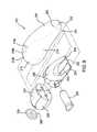
- FIG. 3is an exploded view of the massager of FIG. 1 ;
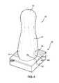
- FIG. 4is a perspective view of the massager of FIG. 1 assembled with a charging base
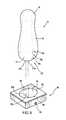
- FIG. 5is an exploded view of the assembly of FIG. 4 ;
- FIG. 6is a front perspective view of a massager according to a second embodiment of the present invention.
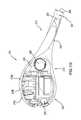
- FIG. 7is an exploded view of the massager of FIG. 6 ;
- FIG. 8is a front perspective view of a massager according to a third embodiment of the present invention.
- FIG. 9is an exploded view of the massager of FIG. 7 ;
- FIG. 10is a cross-sectional view of the massager of FIG. 7 .
- FIGS. 1 and 2show an embodiment of the present invention, wherein a massager 10 includes a first end 12 , a second end 14 and a midsection 16 .
- first end 12is in the form of a base end that includes controls for various electronic features of the massager 10 and also houses most of the electronic components of the massager 10 , as discussed below with reference to FIG. 3 .
- First end 12is generally sized and shaped to provide a portion of the massager 10 for the user to grasp during use of the massager 10 , but is also designed to provide a useable area for the massager 10 . Accordingly, the majority of first end 10 is substantially smooth and forms a continuous, rounded surface, with the exception of the controls 18 and the charging contacts 20 .
- Midsection 16generally forms the transition or connection between first end 12 and second end 14 .
- midsectioncan take on a variety of specific shapes that may be largely dictated by the actual shapes of first and second ends 12 , 14 .
- midsection 16should be generally smooth throughout and should form substantially smooth transitions with and between first end 12 and second end 14 .
- midsection 16may contribute to aspects of the massage characteristics of the massager 10 , as will be discussed below.
- Control housing 28also encloses most of the electronic components of massager 10 such as a rechargeable battery and printed circuit board (“PCB”).
- the PCB 31includes buttons that are used to control electronic functions of massager 10 , such as turning on and off the electronic motor held within motor unit 26 as well as controlling the speed at which the motor rotates. Further control functions of the motor are disclosed in co-pending U.S. patent application Ser. No. 11/971,825 to Imboden, et al. (hereinafter, “the '825 Application”) entitled “Rechargeable Personal Massager” and filed Jan. 1, 2008, the entire disclosure of which is incorporated by reference herein.
- the PCB 31also controls the charging of the battery and, accordingly, is electronically connected to charging contacts 24 a , 24 b.
- control housing 28is structured so as to be useable in a number of different massage devices that have varying shapes for their respective midsections and second ends. (See, for example massager 110 , as shown in FIGS. 6 and 7 , and massager 210 , as shown in FIGS. 8-10 .)
- control housing 28can have a shape intended to be common to the first end 12 of the device with a feature for connection thereto of different flexible substructures.
- control housing 28includes a pair of holes 29 formed between mating halves of control housing 28 such that the two halves can be assembled to capture a mating portion of midsection 30 such as a pair of mushroom tabs (not shown) to secure flexible substructure 30 to control housing 28 .
- an adhesivecan also be used to further secure the attachment.
- the PCB 31 included in control housing 28can also be adapted to control common functions between various massager embodiments that share a common control housing.
- the PCB 31can further be accessible during assembly of the device, such as by opening the housing to add additional elements to the PCB 31 to adapt the control features to the specific embodiment of the massager with which it is used.
- Such adaptationscan include, for example, appropriate handling of the number and/or size of the vibrating motors used (which can result in varying power requirements) and can be achieved, for example, by soldering specific jumpers thereto, as would be understood by one of ordinary skill in the art.
- Variations of PCB 31 that are programmable or otherwise customizable to work with additional variations in massager types and configurationsare contemplated.
- PCB 31can include flash memory or the like that can allow customization of massager control by changing firmware, rather than hardware.
- buttons 70 a , 70 b , 70 c of PCB 31are positioned beneath cover 32 , which is substantially flexible such that when the user presses one of the controls 18 a , 18 b , 18 c , cover 32 deforms therebeneath.
- Cover 32is adaptable to provide a transition between a common control housing 28 and midsections of various configurations that may be used in a number of devices having different midsection and second end shapes.
- the use of cover 32provides a smooth transition between control housing 28 , and the flexible boot 22 , especially during manipulation of controls 18 a , 18 b , 18 c .
- Cover 32further prevents any adhesives used during assembly of massager 10 from interfering with the functioning of controls 18 a , 18 b , 18 c .
- different coverscan be used with corresponding flexible substructures wherein the different covers are configured to match the profile the portion of the control housing to which they connect and to vary along the remaining outside surface, according to the desired shape of the flexible substructure. This arrangement allows for a transition to the common control housing 28 from the various flexible substructure shapes to extend farther toward first end 12 than would otherwise be possible.
- Button tree 64is positioned inside control housing 28 and is structured to depress a corresponding one of buttons 70 a , 70 b , 70 c in response to the deformation of cover 32 when controls 18 a , 18 b , 18 c are depressed.
- button tree 64includes lever arms 72 a , 72 b , 72 c that correspond to buttons 70 a , 70 b , 70 c and provide a link through cover 32 to corresponding controls 18 a , 18 b , 18 c .
- the various forms of the coverthat may be used in connection with the modular assembly structure described above are structured to maintain a similar “button feel” between different variations thereof.
- This button feelcan include, for example, the force required to depress the controls and the distance of travel required for the manipulation of the controls to achieve their desired function. Consistent button feel can be achieved, for example, by forming the different variations of the cover to share a common thickness. Such a formation can result in a gap between the button tree and cover 32 . In such instances spacers 86 a , 86 b can be included between buttons 70 a , 70 b , 70 c and button tree 64 to take up this gap and to maintain a consistent travel distance for buttons 70 a , 70 b , 70 c compared to other embodiments.
- Mode control 18 cpreferably cycles through various additional electronic functions or massage modes. Examples of these modes include: constant, sine curve slow, sine curve fast, ramping, and pulsing. These modes can additionally include control of multiple motors in embodiments of the massager including more than one motor. Examples of such modes are further described in the '825 Application.
- Controls 18 a , 18 b , 18 ccan also be used to activate a “secret mode” of operation for massager 10 by, for example pressing specific ones of controls 18 a , 18 b , 18 c in a predetermined sequence.
- the secret modecan include the implementation of a certain vibrational characteristic for massager 10 or can include the implementation of a “chaos” mode, whereby the motor is made to vibrate in a random one of its prescribed modes at a random power level for a certain period of time before the mode is switched to another randomly-selected mode, and so forth.
- the secret mode or functioncan be one that is not described in the manual that is distributed with the device when it is sold.
- the sequencemay involve pressing a combination of buttons to unlock the secret mode.
- the existing functional buttons on the devicesmay not provide access to that function or mode and a code must be entered by using existing buttons to unlock and activate the mode.
- a functionmay not be necessarily considered to be a “secret” to the user, but there may be no corresponding button that is designated to activate the mode. Pressing a combination of different buttons, such as pressing “+” twice and “ ⁇ ” once within a few seconds, or by pressing the “+” and “ ⁇ ” controls within about 1 ⁇ 2 second of each other three times in sequence, for example, can trigger the mode.
- buttons for providing different functions on the massagerare being used in an unconventional way (not having a known set function for their use in combination or not corresponding to their designated use) to cumulatively find a new operation of the massager, specifically a massager.
- such “secret” functionalitymay be related to a game function of the massager. This can include using the geometry of the massager, in connection with the vibration of the motors to, for example, cause the massager to rotate on a surface for a random amount of time or through a random rotational distance. This allows the massager to be used to control a “spin-the-bottle” type game.
- the vibration levelcan be controlled by two methods:
- controls 18 a , 18 b , 18 ccan be used to turn massager 10 off and to enter a “lock” mode, preferably in accordance with the following exemplary scheme:
- control methods describedare by way of example only and are not intended to be limiting with respect to the operation of massager 10 .
- Different control schemes, employing more, fewer, or different controlscan be implemented by those with ordinary skill in the art.
- Control housing 28further preferably includes an LED light assembly 73 that is comprised of a LED light source on PCB 31 and a light pipe that carries the light emitted by the LED light source to the end thereof.
- the light carried to the end of the light pipe of LED assembly 73is visible through a hole 75 in cover 32 in control housing 28 and further visible through boot 22 due to the preferred material characteristics thereof.
- LED light assembly 73can be used to provide information to the user of massager 10 regarding the status of the massager's operation. For example, LED light assembly 73 can indicate when the massager is on, off, or in locked mode by flashing or constantly illuminating according to a prescribed pattern.
- LED light assembly 73can also provide information regarding the charge level of the battery, for example by illuminating for a predetermined amount of time or flashing a predetermined number of times when massager 10 is removed from its charging base 90 .
- a larger LED light assembly, a plurality of LED light assemblies, an electroluminescent panel, an OLED or other light sourcecan be included in massager 10 , possibly at varying locations throughout the interior of massager 110 , such as beneath boot 22 on or near second end 114 , so as to illuminate substantially the entire form of massager 10 or to illuminate a portion of massager 10 at one or more desired locations.
- Such “night light” or lighting functionscould also include forming the internal components, where possible, from a translucent material and can be incorporated in the communicative aspects of LED light assembly 73 , discussed above.
- Boot 22is preferably formed from a flexible, rubbery material such as a silicone or a thermoplastic elastomer (“TPE”).
- boot 22is molded as a separate, unitary structure and is fitted over the assembled internal components of massager 10 .
- the flexible nature of the silicone or TPEallows boot 22 to flex and stretch, as necessary, to fit over any larger portions of massager 10 during assembly.
- a flexible adhesive, such as a silicone-based adhesiveis preferably applied between the internal components of massager 10 and the inside surface of boot 22 to maintain the appropriate position of boot 22 .
- a low-viscosity adhesiveis applied to achieve a substantially thin and even layer of adhesive.
- boot 22The use of an adhesive to secure boot 22 to the internal components of massager 10 help to keep boot smooth and substantially free of bumps and wrinkles during use, particularly when massager is bent or flexed as allowed by flexible midsection 30 . Further, the use of adhesive allows boot 22 to provide additional structural support for the internal components of massager 10 such as between motor housing 26 and flexible substructure 30 or between flexible substructure 30 and control housing 28 .
- the material used to form boot 22preferably has a durometer of between Shore 35 A and Shore 44 A, which provides a substantially soft and pliant tactile quality for boot 22 when formed at a preferred material thickness of between 1 mm to 10 mm and, more preferably, between 2 mm and 5 mm. It is noted that the preferred material thickness can vary with the desired material characteristics of boot 22 , such as flexibility, softness, etc.
- Boot 22forms a flexible skin that preferably waterproofs the entire structure of massager 10 , with the exception of the single boundary at its opening. This opening is substantially sealed by the adhesive between boot 22 and control housing 28 around the opening of boot. A portion of control housing 28 that is located within the opening of boot 28 is substantially waterproofed by using adhesive to seal any openings or seams therein, including the seam between halves of control housing 28 and the openings for the leads that connect the charging contacts 24 a , 24 b to the PCB 31 through control housing 28 .
- Charging contact cap 20fits into the opening in boot 22 and is affixed to control housing 28 .
- Charging contact cap 20is comprised of two metal contacts 24 a , 24 b that are insert-molded into a plastic structure.
- This production method(rather than assembly of separate parts) essentially fuses the parts together, making them a sealed, unified assembly.
- the assembly of charging contact cap 20 onto control housing 28which is preferably achieved by a combination of pressure-fit and glue, captures a portion of boot 22 therebetween, providing pressure on boot 22 , around its opening, to create a seal therebetween and to prevent boot 22 from pulling away from control housing 28 around the opening thereof or from charging contact cap 20 around the edge thereof.
- An O-ring or gasket, preferably formed from siliconeis positioned within channel 25 formed in charging contact cap 24 between charging contacts 24 a , 24 b .
- Channel 25is positioned to abut a portion of control housing 28 beneath charging contact cap 24 , forming a seal therebetween, and, accordingly, isolating charging contacts 24 a and 24 b and their respective leads from each other.
- This arrangementhelps to substantially prevent shorting between contacts 24 a and 24 b due to water that may enter beneath the outer portion of the charging contact, as defined by the channel 25 .
- the result of this preferred combination of sealing measurespreferably ensures a substantially waterproof seal, resulting in a completely-submersible massager 10 . Additional waterproofing measures can be employed within massager 10 , such as by forming joints between mating parts of control housing 28 with v-grooves that substantially accumulate glue therein when used to secure the parts together.
- the use of adhesive to secure boot 22 to the internal components of massager 10also helps to waterproof massager 10 by substantially sealing boot 22 over any seams in motor housing 26 or control housing 28 .
- a selectively permeable membranecan be included in control housing 28 .
- the selectively permeable membraneis preferably formed from Gore-TexTM or other, similar materials that are constructed to allow permeation by air, but not by water or other liquids. Accordingly, this structure, acts as a valve for air movement, while retaining the desired waterproofing characteristics of massager 10 .
- Adequate movement of air through such a valvecan be achieved through an area as small as 3 mm 2 or less, and more preferably 1.5 mm 2 or less.
- the valveis preferably in the form of a Gore-TexTM membrane that is secured by into an appropriately-sized section of plastic tubing, preferably by insert molding the tubing around the Gore-TexTM membrane or by alternative methods such as adhesive, heat seating, ultrasonic welding or the like.
- a mechanical valvesuch as a check-valve or the like can be used. The valve is then secured, preferably by glue or alternatively by ultrasonic welding or the like, into a corresponding hole in control housing.
- valve holeis preferably positioned on control housing 28 so as to locate valve beneath charging contact cap 24 in the portion thereof that is outside of channel 25 .
- a notch 88is preferably formed in charging contact cap 20 to allow the air passing through the valve to escape therethrough to the outside of massager 10 , or vice-versa.
- Motor unit 26contains an electronic motor with an output shaft having an offset weight attached thereto (see FIG. 7 detail and the description of the '825 Application) such that a vibration is created by the motor when running.
- the motoris electronically connected to the PCB 31 , which controls and powers the motor via the battery, by wires that run through flexible substructure 30 .
- motor unit 26is positioned within second end 14 of massager 10 .
- FIG. 3can be preferred, where the size and shape of second end 14 permits, because it achieves the maximum amount of transfer from the vibrating motor to the point of application for massager 10 .
- Flexible substructure 30is formed to provide a level of compliance or flexion to the structure of massager 10 .
- the flexibility provided by flexible substructure 30has many benefits, including making massager 10 more compatible with different portions of the human body or to compensate for variations within specific body parts between different individuals. Additionally, the flexibility can increase comfort and provide a more lifelike feel for massager 10 .
- flexible substructure 30can be formed to have a certain amount of “memory”, either by material selection or by including additional structures therein, such as pliable wire, hinges, spines, a flexible conduit or the like.
- additional structureswould preferably be substantially covered by, or embedded in, the material of flexible substructure 30 .
- spine 77as shown in FIG.
- spine 77can be adapted to include a mechanical structure that can bend and hold a shape and can be further adapted to affix to motor housing 26 at one end and to control housing 28 at the other.
- the use of such structures incorporating some degree of memorycan allow the user of massager 10 (or massager 110 or massager 210 ) to direct the force applied by massager, and preferably by second end 14 , to a specific part or parts of the body or can allow for second end 14 to reach to a specific part or parts of the body that otherwise might be more difficult to reach.
- Flexible substructure 30also provides support for motor unit 26 within the massager 10 , protects the wiring connections between motor unit 26 and control housing 28 , and supports the outer boot 22 during flexion of massager 10 so that the skin formed by boot 22 is as smooth as possible before, during, and after flexion.
- flexible substructure 30is formed from IPE, or other flexible material such as silicone or the like, of a higher durometer than that used for boot 22 .
- the durometer of the TPE usedcan preferably fall within a range of 44 Shore A to 70 Shore A.
- Such characteristicsinclude the desired thickness, of both the substructure 30 and the portion of massager 10 in which it is used, the desired flexibility, the structural support of motor unit 26 and the amount of vibration transmission through flexible substructure 30 that is desired, among others.
- the physical structure of the flexible substructure 30can be tuned to provide the desired flexion/compliance characteristics.
- the thickness 64 of the cross-section of flexible substructure 30 in a X-directionis greater than the thickness 66 of the cross-section of the flexible substructure 30 in the Z-direction, as shown in the axes of FIG. 3 .
- the flexible substructure 30being more flexible when bent on the Y-Z plane than when bent on the X-Y plane.
- the ratio of thickness 66 to thickness 64is less than 1 and, more preferably, less than about 0.75.
- the cross-sectioncan be narrowed in specific areas to create a “hinge” in a specified area or tapered to vary the flexion along the length of the substructure.
- Ribscan also be integrally formed into the shape of the flexible substructure to change the flexion characteristics thereof, as desired.
- the connections to adjacent or enclosed partscan be adjusted to change the flexion or compliance characteristics.
- the distance to which motor unit 26 extends into flexible substructure 30 in the embodiment of FIGS. 1-3can be changed to yield different characteristics for the assembled structure.
- a first and second direction different from horizontal and vertical direction mentioned abovemay be implemented (e.g., not in perpendicular orientation to each other).
- a relatively thin piece of materialcan be included in flexible substructure by insert-molding, assembly using adhesives, or the like, to form a spine 77 that runs through a portion of the interior of flexible substructure 30 .
- the thin piece of material that forms spine 77is of a material, such as PET, that is, overall, less flexible than the material used for flexible substructure 30 . This allows for the spine 77 to be flexible in the desired direction of flexion for substructure 30 (the direction on the Y-Z plane in the illustrated embodiment) by virtue of the low material thickness 76 , but to also be relatively rigid in the other direction (the direction on the X-Y plane in the illustrated embodiment) due to the width 78 of the material.
- the ratio of thickness 66 to thickness 64has a reduced effect on the flexion characteristics of flexible substructure 30 and is substantially free to vary according to other design aspects.
- the flexion characteristics of flexible substructurecan be adjusted, as desired, by changing the configuration of spine 77 , such as by altering the shape (e.g., tapering spine 77 along its length), or adjusting the thickness 76 , its width 78 or the distance by which it extends into flexible substructure 30 .
- flexible substructure 30 and spine 77are structured such that the ratio of the force required to achieve flexion in the direction on the Y-Z plane to the force required to achieve flexion in the direction on the X-Y plane is less than about 0.75 and more preferably about 0.5.
- Charging base 90has a pair of electrical contacts 92 a , 92 b that align with respective ones of the contacts 24 a , 24 b included in charging contact cap 20 to provide positive and negative connections to provide power to massager 10 , preferably for recharging the battery contained within control housing 28 .
- Charging base 90is preferably formed so as to be as low as possible while still retaining massager 10 on base 90 so as to maintain electrical contact between charging contacts 24 a , 24 b , and contacts 92 a , 92 b . In a preferred embodiment, as illustrated in FIGS.
- base 90is further structured to hold massager 10 in a substantially vertical arrangement, although other configurations are possible.
- the massager and base of the present inventioncan take various forms, including those beyond which are specifically shown herein.
- all such massagerscould have the same general shape for the portion of first end 12 that surrounds charging contact cap 20 (which could also be substantially similar between different massager variations). This portion would be that which fits within cavity 94 to provide the desired support for the massager 10 .
- the various shapes of the different massagerscan diverge after such a portion.
- the lower the height of the base 90the more easily a smooth transition between the common and unique portions of the various massagers can be made.
- Having the massager 10 “standing” in a substantially vertical, or upright, positionis generally intuitive and ergonomic for the user, that is, such an orientation makes it easy to pick up and put down the massager 10 .
- a base that has a low profilemakes it easier to place the massager 10 into the charging position without requiring excessive accuracy.
- base 90is structured such that it its relatively wide in the horizontal (i.e. X-Y) plane so that it will not tip over, even when massager 10 is inadvertently placed in base 90 on an angle.
- base 90is preferably low enough such that controls 18 a , 18 b , 18 c and LED light assembly 73 are substantially visible when massager 10 is on base 90 , although a portion of control 18 c may be not be visible.
- Other configurations for base 90are contemplated, such as a configuration with no indentation surrounding contacts 92 a , 92 b , but rather strategically placed supports, preferably at least two, that provide support to key areas of massager. Such a configuration can allow for further variations among different forms of the massagers with which base 90 can be used.
- contacts 92 a and 92 b of base 90 and the contacts 24 a and 24 b of massager 10are preferably formed to reduce the accuracy with which the massager 10 must be placed on base 90 in order to make a proper electrical connection therebetween.
- contacts 24 a and 24 b of massager 10are in the form of concentric rings
- contacts 92 a and 92 b of baseare in the form of pins, spaced radially within cavity 94 to align with one of the rings. This allows contact to be made regardless of the rotational orientation between massager 10 and base 90 along the long axis of the massager 10 .
- the angle of placement at which appropriate contact can be madeis increased.
- the surface of cavity 94can be made of substantially smooth and polished polycarbonate (PC) or ABS plastic that will positively interact with the somewhat tacky surface of the soft silicone or TPE boot 22 to provide increased adhesion.
- a notch 96can be formed near the upper edge of cavity 94 to provide clearance for control 18 of massager 10 and to “key” massager 10 in place on base 90 .
- Power input 98allows for the connection of charging base to a power source, such as an A/C outlet via a power adapter or the like.
- the vibration sourcecan be disposed distal from the massage end of the massager.
- the vibration source distal from the point intended to massageBy placing the vibration source distal from the point intended to massage, the flexion movement of the massage end can be greater than when the vibration source is placed proximate the end to be held by a user.
- placing the vibration source distal from the massage endallows for shaping the massage end as desired. With no bulky vibration source near the massage end, the massage end can be shaped to complement various body orifices or surfaces without being limited by the size of the electronics or a vibration source.
- massager 10has to be large enough overall for it to feel satisfying, both during massage, and in particular when used to provide sexual stimulation by insertion into the vagina, etc. It is also important, however, to make massager 10 not so large as to feel inappropriate to most users.
- midsection 16preferably meets two criteria: that it is long enough so that second end 14 can extend about 2-3 inches into the vagina, particularly along the anterior side thereof in order to reach the “g-spot” while being easily held by first end 12 ; and, that it is short enough to be approachable (i.e., not daunting, overwhelming, or embarrassing) in appearance for a majority of users. Additionally, it is preferred that midsection 16 form a relatively narrow “waist” between first end 12 and second end 14 to create a varying diameter along the longitudinal axis of massager 10 so as to provide additional stimulation to the entrance of the vagina (or anus) as it stretches and relaxes the tissues during insertion and withdrawal therefrom.
- midsection 16tapers from a waist that is, at the most narrow point, at least about 7.5% more narrow than second end 14 , and more preferably at least about 10% more narrow than second end 14 .
- the relative widths used to calculate the percentage decrease from second end 14 to the most narrow point of midsection 16can be taken along the cross-sectional width, length, or both width and length of the second end 14 and midsection 16 .
- such taperingoccurs smoothly over a length that is not so long as to reduce the perceptibility of the change by the user, such as over a length of 60 mm or less.
- the taperingcan occur over a short distance in the form of a step or the like.
- Other possible arrangements for the surface of both second end 14 and midsection 16can be used to provide similar stimulation, such as the use of ribs, bumps, various textures, multiple or repeating sections of tapering or widening, etc.
- a variation of the massagerincludes a midsection 116 that splits to form a second end 114 having a plurality of projections 134 .
- the embodiment of FIGS. 6 and 7shows two substantially similar projections. If desired in other embodiments, further projections can be included and the projections can be of varying sizes and functions (such as providing for attachment to or stimulation of various body parts).
- Massager 110is structured such that midsection 116 is flexible, allowing the user to move and adjust projections 134 , as desired to provide different actions or sensations.
- projections 134can be compressed together so that the respective ends thereof touch so that they can be inserted together into a single cavity or pressed together to grip sensitive tissue, such as the clitoris. Further, it may also be preferable for projections 134 to be moveable apart from one another so that they can stimulate different adjacent areas, simultaneously, such as the clitoris and the entrance to the vagina, the vagina and the anus, the testicles, the anus and the perineum, etc. Such flexion is dictated by both the materials (such as flexible substructure 130 , See FIG. 7 ) and by the size/shape of the features. For example, the valley 136 formed between projections 134 is preferably deep enough to permit such movement.
- flexible substructure 130can vary from that which is shown in FIG. 7 .
- flexible substructuremay extend farther up along motor housings 126 and/or may terminate along a plane oriented substantially perpendicular to or up to about 45° to the long axis of motor housings 126 , although other variations are possible.
- the ends of projections 134are preferably sized to be small enough (and close enough together) so that they can both be applied to the clitoris simultaneously, either the top and bottom or the left and right sides thereof, depending on the orientation of massager 110 .
- projections 134have a length between about 1 cm and 8 cm, although variations are contemplated in which longer or shorter projections would be desired. As shown in FIG.
- massager 110includes two motor units 126 , each including a motor housing 138 , an end cap 140 , an electronic motor 142 and an offset weight 144 .
- the functions of the motor units 126is substantially the same as discussed above with respect to FIGS. 1-3 .
- Each of the motor unitsis positioned within a respective projection 134 to provide individual vibration thereto.
- the motorscan be controlled by the PCB 31 that is held within control housing 128 (as discussed above with respect to FIGS. 1-3 ). Further, in a preferred embodiment, the motors 142 can be made to vibrate at different speeds, providing a different sensation between projections 134 when used separately, or providing overlapping “beats” when used together.
- flexible substructurebe flexible enough, through material selection and structure, that the individual motor units 126 can vibrate the projections 134 at the selected frequencies without being adversely affected by the operation of the other motor.
- the projections 134are shown having a substantially smooth surface.
- FIGS. 8 and 9show a further embodiment of a massager 210 in which second end 214 has an indentation 246 formed therein, which forms a flexible membrane 250 surrounded by a relatively more-rigid rib 252 .
- the incorporation of the membrane 250allows for tactile sensation to be transmitted through massager 210 both from, for example, the fingers of the user on one side to a part of the user's (or another person's) body on the other side. This allows the holder of the device to both provide their own, unique sensation to the point of application and to receive tactile feedback from the anatomy of the point of application.
- the rib 252compliments the membrane 250 by maintaining the structure and general shape of second end 214 , while preferably allowing some degree of and transmitting vibration from the motor unit 226 to the point of application.
- flexible substructure 230is formed having extensions 254 that surround a portion of membrane 250 , which is formed substantially entirely within boot 222 , and give the preferred support and vibration transmission to membrane 250 .
- the physical structure as well as the material characteristics of flexible substructure 230can be adjusted to achieve the desired flexibility and transmission.
- flexible substructure 230is preferably formed from a TPE having a durometer in the range between about 50 Shore A to about 70 Shore A.
- the length of the extensions 254can also be adjusted to achieve the desired qualities of these characteristics.
- extensions 254have a length 256 of between about 1 cm and 6 cm, and more preferably about 3.5 mm. These dimensions preferably represent an extension equal to between about 70% and 100% along the sides of the membrane 250 . Additionally, it may be preferable to form flexible substructure 230 such that extensions are spaced apart at a distance 262 from each other of between about 15 mm and 120 mm and more preferably about 25 mm. Other embodiments of the massager are contemplated in which extensions 254 are curved inward toward each other to further encircle membrane 250 or in which extensions 254 meet each other at the ends thereof, completely encircling membrane 250 .
- the structure of flexible substructure 230including extensions 254 , along with the shape of boot 222 , including rib 252 , result in a membrane 250 having a size of at least about 10 mm, measured at approximately the longest point, by at least about 10 mm, measured at approximately the widest point.
- a sizeis approximately the lowest that would be reasonable useful in an embodiment designed to transmit the force applied to membrane 250 by a single finger of a user, with no included room to accommodate finger motion over membrane 250 .
- a structureis contemplated in which membrane 250 is adequately sized to be used with all four fingers of a user with included room for movement of the fingers within membrane 250 .
- membranecan measure up to approximately 120 mm by 120 mm.
- membrane 250is about 35 mm long, measured at approximately its longest point, by about 25 mm wide, measured at approximately the widest point.
- Second end 214 of massager 210preferably has as thin a profile as possible, while still maintaining the desired structural and vibrational aspects of the massager.
- second endhas a thickness 258 (shown in FIG. 10 ) between about 4 mm and 15 mm, but can vary depending on the type of material used and the size of membrane 250 .
- Such a thin profilepreferably allows massager, and in particular second end 214 to fit comfortably between two people during sexual intercourse, including when in the “missionary position”, to provide targeted sexual stimulation.
- first end 212 and the transition between first end 212 and midsection 216is preferably shaped to fit comfortably within and beneath a woman's or man's hand so that it is cupped in the palm and the fingers naturally rest along its length, extending into contact with the membrane 250 such that manipulation thereof can be achieved using the fingers.
- the thinning of the material that comprises boot 222is preferably adjusted to make membrane as pliable as possible when used as such, without compromising the structural integrity of membrane 250 and while maintaining enough rigidity to transmit vibration therethrough.
- membrane 250has a thickness 260 of between about 0.5 mm in and 5 mm, depending on the desired size of membrane 250 , the durometer of the material comprising membrane, the desired flexibility of membrane 250 and the durability requirements for massager 210 . In some embodiments having a low durability requirement, thickness 260 can be as low as 0.25 mm. In a preferred embodiment, of massager 210 , having a membrane size of approximately 25 mm by 35 mm, and being constructed of material having a durometer of between 35 Shore A to 44 Shore A, thickness 260 is preferably between about 0.5 mm and 2 mm, and more preferably about 1 mm.
- further embodimentsare contemplated that include embedding sources of vibration, such as piezoelectric devices within membrane or embedding other objects, such as a small steel ball or the like, within membrane 250 .
- Such featureswhen embedded in membrane, can improve vibration of membrane 250 , vibration transmission from the fingers of the user to membrane 250 and the parts of the body to which massager 10 is applied, or the ease of deformation of membrane 250 by the user.
- Such embodimentsmay allow for different membrane characteristics, such as thicker or thinner material. Textural features can be added to the bottom surface of membrane 250 (i.e., the surface applied to the body), such as slits that expand into ribs when membrane 250 is stretched, bumps, ridges, or the like.
- Membrane 250could be substantially open, with no rib 252 , on one end, such as near the tip of massager 210 , or could have an opening at its center, such as for a finger, a user's penis, or another device, such as a non-vibrating form (i.e., a dildo) or another vibrator, to pass through.
- a non-vibrating formi.e., a dildo
- Other forms of a massagerare contemplated that incorporate a flexible membrane.
- a membrane of a flexible materialcould be supported by a rigid frame, with or without a soft or pliable covering and/or be included with a device that substantially lacks a midsection or first end.
- the flexible materialmay be held by a supporting frame, wherein the supporting frame is not covered by a soft pliable covering.
- massager 210Other functional aspects and structures of massager 210 , including the use and interaction with a charging base, such as base 90 shown in FIGS. 4 and 5 ) are preferably substantially similar to those discussed above with respect to the embodiments of FIGS. 1-5 .
- base 90is adaptable to receive mating ends of various devices having different structures than those shown. Additional structures can be designed and added to new products. If desired contactless, or wireless, charging devices, such as inductive charging, may be used.
- the charging endmay, if desired be substantially smooth and may include a soft overlying layer where the charging contacts are otherwise shown as exposed.
- the massager devicemay be adapted to use a remote control. Examples of such incorporation are disclosed in the '825 Application as well as in co-pending U.S. patent application Ser. No. 11/344,987 to Imboden, et al.; Ser. No. 11/245,456 to Imboden, et al.; and Ser. No. 11/345,455 to Imboden, et al., the entire disclosures of which are incorporated herein.
- the massager devicemay further be implemented in an embodiment that uses standard (i.e., non-rechargeable) batteries.
- charging contact cap 20could, for example, be replaced by a cap over a cavity for receiving a battery or plurality of batteries.
- the entire device or portions of it, such as the second end of the massagerare not covered by a soft elastomer, but rather, for example, structures in which the working surface is constructed from plastic.
- the chargercan be self-aligning and can be curved so as to be adapted to receive the massager.
Landscapes
- Health & Medical Sciences (AREA)
- Animal Behavior & Ethology (AREA)
- Veterinary Medicine (AREA)
- Public Health (AREA)
- General Health & Medical Sciences (AREA)
- Life Sciences & Earth Sciences (AREA)
- Rehabilitation Therapy (AREA)
- Physical Education & Sports Medicine (AREA)
- Pain & Pain Management (AREA)
- Epidemiology (AREA)
- Reproductive Health (AREA)
- Engineering & Computer Science (AREA)
- Biomedical Technology (AREA)
- Heart & Thoracic Surgery (AREA)
- Vascular Medicine (AREA)
- Percussion Or Vibration Massage (AREA)
- Massaging Devices (AREA)
Abstract
Description
- Clicking “+”
control 18aonce increases the vibration level by one level - Clicking “−”
control 18bdecreases it by one level - Clicking “+” when
massager 10 is on level 5 (the top speed) has no effect - Clicking “−” when
massager 10 is on level 1 stops all vibration, turningmassager 10 off; or,
- Clicking “+”
- Pressing and holding “+”
control 18acauses the vibration level to step up through the levels, with 0.25 s between steps, until the button is released, ormassager 10 reaches its top speed (LEVEL 5). - Pressing and holding “−”
control 18bcauses the vibration level to step down through the levels, with 0.25 s between steps, until the button is released, ormassager 10 reaches level 1. (To then turn massager10 all the way off, “−”control 18bmust then either be held for an additional 0.5 s, or can be clicked or pressed again.)
- Pressing and holding “+”
- Clicking or pressing and holding “−”
control 18bormode control 18chas no effect whenmassager 10 is off. (Clicking orpressing mode control 18cdoes not change the mode of vibration.) - Clicking “+”
control 18aturns massager10 on and begins vibration at level 1. - Pressing and holding “+”
control 18aturns massager10 on and begins vibration level 1 and continues to ramp up the speed until the button is released.Massager 10 will then continue to run at that speed - When Vibrating Massager is turned on, the mode is always the same as when
massager 10 was last turned off.
- Clicking or pressing and holding “−”
- Pressing and holding “+”
control 18aandmode control 18csimultaneously for 1.5 seconds locks and unlocksmassager 10. - When
massager 10 is on, and “+”control 18aandmode control 18care pressed simultaneously for 1.5 seconds, the motor (or motors, if multiple motors are used) stops andmassager 10 is locked. - When
massager 10 is off, and the “+”control 18aandmode control 18care pressed simultaneously for 1.5 seconds, the motor stays off andmassager 10 is locked. - Whenever
massager 10 is unlocked it will turn on and begin vibrating at level 1 and in the same mode it was in just prior to being locked. - Placing
massager 10 inbase 90 unlocks it and puts it in the off mode. Thereforemassager 10 is always in the off mode (and not locked) when it is removed frombase 90.
- Pressing and holding “+”
Claims (11)
Priority Applications (2)
| Application Number | Priority Date | Filing Date | Title |
|---|---|---|---|
| US12/868,498US8821421B2 (en) | 2009-08-26 | 2010-08-25 | Massage device with flexible substructure |
| US14/613,200US9138373B2 (en) | 2009-08-26 | 2015-02-03 | Massage device |
Applications Claiming Priority (2)
| Application Number | Priority Date | Filing Date | Title |
|---|---|---|---|
| US23718609P | 2009-08-26 | 2009-08-26 | |
| US12/868,498US8821421B2 (en) | 2009-08-26 | 2010-08-25 | Massage device with flexible substructure |
Related Child Applications (1)
| Application Number | Title | Priority Date | Filing Date |
|---|---|---|---|
| US201414474256AContinuation | 2009-08-26 | 2014-09-01 |
Publications (2)
| Publication Number | Publication Date |
|---|---|
| US20110071445A1 US20110071445A1 (en) | 2011-03-24 |
| US8821421B2true US8821421B2 (en) | 2014-09-02 |
Family
ID=43649905
Family Applications (1)
| Application Number | Title | Priority Date | Filing Date |
|---|---|---|---|
| US12/868,498Active2031-05-10US8821421B2 (en) | 2009-08-26 | 2010-08-25 | Massage device with flexible substructure |
Country Status (6)
| Country | Link |
|---|---|
| US (1) | US8821421B2 (en) |
| EP (1) | EP2470145A4 (en) |
| JP (2) | JP2013502994A (en) |
| KR (1) | KR20120056854A (en) |
| CN (1) | CN102711708A (en) |
| WO (1) | WO2011028576A2 (en) |
Cited By (24)
| Publication number | Priority date | Publication date | Assignee | Title |
|---|---|---|---|---|
| US20140171841A1 (en)* | 2012-12-18 | 2014-06-19 | Sos Novelties, Inc | Vibrator |
| US9144531B2 (en) | 2012-08-13 | 2015-09-29 | Crave Innovations, Inc. | Vibratory actuator and device for sexual stimulation |
| USD746161S1 (en)* | 2015-01-22 | 2015-12-29 | Tempdrop Ltd. | Temperature sensing device |
| USD764172S1 (en)* | 2015-01-22 | 2016-08-23 | Wenzhou Onicare Electrical Technology, Co. | Sonic face brush |
| US20180085952A1 (en)* | 2016-09-28 | 2018-03-29 | Braun Gmbh | Electric shaver |
| USD825073S1 (en)* | 2017-02-03 | 2018-08-07 | Novoluto Gmbh | Erotic massage vibrator |
| USD837396S1 (en)* | 2014-04-18 | 2019-01-01 | Oculeve, Inc. | Nasal stimulator probe |
| US10201472B2 (en) | 2014-06-17 | 2019-02-12 | Neue Kinetik, LLC | Tri-motion tactile stimulation device |
| DE212017000189U1 (en) | 2016-07-28 | 2019-02-28 | Sergey Evgenievich Topolev | Apparatus for massage with a stimulating element, its application and manufacturing process |
| DE212017000190U1 (en) | 2016-07-28 | 2019-02-28 | Sergey Evgenievich Topolev | Device for massage with a rounded element, its application and manufacturing process |
| USD862722S1 (en)* | 2017-05-06 | 2019-10-08 | Ievgen Iurchenko | Vibrator for massage |
| USD863588S1 (en)* | 2018-10-18 | 2019-10-15 | Shenzhen Svakom Technology Co., Ltd | Massage device |
| US10857063B2 (en) | 2013-09-23 | 2020-12-08 | Novoluto Gmbh | Stimulation device |
| US11446203B2 (en) | 2019-06-26 | 2022-09-20 | Crave Innovations, Inc. | Sexual stimulation systems and methods of use |
| US11471371B2 (en) | 2017-07-27 | 2022-10-18 | Sergey Evgenievich Topolev | Massage device having element that straightens, method for use thereof, and method for manufacture thereof |
| USD978574S1 (en)* | 2021-05-18 | 2023-02-21 | Somnox Holding B.V. | Anatomical cushion |
| USD996636S1 (en) | 2021-11-11 | 2023-08-22 | Jj Acquisition, Llc | Massage device having a finger grip |
| USD996638S1 (en) | 2021-11-11 | 2023-08-22 | Jj Acquisition, Llc | Massage device having a finger grip |
| USD996637S1 (en) | 2021-11-11 | 2023-08-22 | Jj Acquisition, Llc | Massage device having a finger grip |
| US12090110B2 (en) | 2015-03-13 | 2024-09-17 | Novoluto Gmbh | Stimulation device having an appendage |
| US12096845B2 (en) | 2018-03-26 | 2024-09-24 | Braun Gmbh | Interface for attaching a brush to a skin treatment device |
| US12171709B2 (en) | 2019-01-24 | 2024-12-24 | Novoluto Gmbh | Stimulation device for a male penis |
| US12251351B2 (en) | 2018-04-04 | 2025-03-18 | Novoluto Gmbh | Device for stimulating the clitoris using a variable pressure field and method for generating a variable pressure field |
| US12329710B2 (en) | 2016-10-05 | 2025-06-17 | Novoluto Gmbh | Stimulation apparatus |
Families Citing this family (49)
| Publication number | Priority date | Publication date | Assignee | Title |
|---|---|---|---|---|
| CN101815493B (en) | 2007-01-09 | 2013-07-03 | 吉米简有限公司 | Rechargeable personal massager |
| US8734322B2 (en)* | 2011-02-02 | 2014-05-27 | Joshua Damien Cordle | Vibrator device |
| USD648862S1 (en)* | 2011-05-18 | 2011-11-15 | Yu Chi Yen | Massage rod |
| CN103781455B (en)* | 2011-07-06 | 2016-08-24 | 莱珞公司 | Remote Control for Personal Massagers |
| US9615994B2 (en) | 2011-07-06 | 2017-04-11 | LELO Inc. | Motion-based control for a personal massager |
| USD668346S1 (en) | 2011-10-03 | 2012-10-02 | Church & Dwight Co., Inc. | Personal vibrator |
| USD673687S1 (en) | 2011-10-03 | 2013-01-01 | Church & Dwight Co., Inc. | Personal vibrator |
| USD673688S1 (en) | 2011-10-03 | 2013-01-01 | Church & Dwight Co., Inc. | Personal vibrator |
| WO2013063499A1 (en)* | 2011-10-26 | 2013-05-02 | Jimmyjane, Inc. | Modular massager system and devices |
| US20130162178A1 (en)* | 2011-12-12 | 2013-06-27 | Sarah Evans | Vibrator |
| US10172762B1 (en)* | 2011-12-16 | 2019-01-08 | Alan Branch | V-band therapeutic wrapping systems |
| PT3524317T (en)* | 2012-01-16 | 2021-06-03 | Swiss Spa System Ltd | Apparatus for electrically assisted skin treatment which can be held |
| CN104284648B (en) | 2012-03-14 | 2017-01-11 | 拉尔夫·齐珀 | Improved sexual stimulation device using light therapy and vibration |
| US10130550B2 (en) | 2012-03-14 | 2018-11-20 | Ralph Zipper | Sexual stimulation device using light therapy, vibration and physiological feedback |
| US10413473B2 (en) | 2012-03-14 | 2019-09-17 | Ralph Zipper | Sexual stimulation device using light therapy, vibration and physiological feedback |
| US20130253386A1 (en)* | 2012-03-22 | 2013-09-26 | Nanma Manufacturing Co., Ltd. | Massage apparatus with a configurable stimulator sleeve |
| CN202682310U (en)* | 2012-07-24 | 2013-01-23 | 爱侣健康科技有限公司 | Mouse wheel type sexual massager |
| USD700347S1 (en) | 2012-11-15 | 2014-02-25 | LELO Inc. | Couples massager |
| US20140162856A1 (en)* | 2012-12-08 | 2014-06-12 | Devin P. Kramer | Neuromuscular Vibration Training Multi-Purpose Handle |
| RS66659B1 (en)* | 2013-01-07 | 2025-05-30 | Foreo Ltd | Skin cleanser |
| CN203168312U (en)* | 2013-03-22 | 2013-09-04 | 王珍珍 | Massage cosmetic bottle capable of vibrating by being touched |
| US20140323929A1 (en)* | 2013-04-30 | 2014-10-30 | Ievgen Valeriyovych Iurchenko | Trainer g-vibe |
| US9949889B2 (en) | 2013-11-11 | 2018-04-24 | Joylux, Inc. | At-home light-emitting diode and massage device for vaginal rejuvenation |
| US9474681B2 (en) | 2013-12-09 | 2016-10-25 | LELO, Inc. | Wearable massager for couples |
| JP2015139626A (en)* | 2014-01-30 | 2015-08-03 | ジェクス株式会社 | Male genitalia massage equipment |
| CN104298285A (en)* | 2014-09-25 | 2015-01-21 | 深圳市无碍互动科技开发有限公司 | Vibrating ball capable of being charged wirelessly and intelligent control system thereof |
| WO2016205959A1 (en)* | 2015-06-24 | 2016-12-29 | Standard Innovation Corporation | Vibratory propagation apparatus |
| SE541782C2 (en)* | 2017-03-08 | 2019-12-17 | Rikard Almgren | Device for stimulation |
| DE102018107939A1 (en)* | 2018-04-04 | 2019-10-10 | Novoluto Gmbh | Direct stimulation device with improved drive |
| LT6684B (en)* | 2018-04-26 | 2019-12-10 | Uab Vilimed | Vibration therapy device |
| USD877537S1 (en)* | 2018-06-25 | 2020-03-10 | Ellen Sheehan | Neck pillow |
| ES1217362Y (en)* | 2018-06-27 | 2019-01-09 | New Wellness Concept S L | DEVICE FOR EXERCISING THE EJACULATORY CONTROL |
| USD907228S1 (en)* | 2018-07-18 | 2021-01-05 | Eran Weinberg | Lactation massager |
| CN110612089A (en)* | 2018-08-10 | 2019-12-24 | 瑞泽麦克斯有限责任公司 | Pain management device |
| USD868988S1 (en)* | 2018-11-26 | 2019-12-03 | Mating Components, LLC | Vibrating electromechanical device |
| RU2705142C1 (en)* | 2018-12-24 | 2019-11-05 | Александр Сергеевич Ковалев | Multifunctional seat, robotic, with programmed control (cnc), for medical and other body cavity procedures; innovative methods and technologies of the procedural room equipment, the doctor's workplace and the doctor's involvement in the therapeutic process |
| USD906731S1 (en)* | 2019-07-15 | 2021-01-05 | Chin-Hui Chiang | Neck cushion |
| USD902426S1 (en)* | 2019-08-13 | 2020-11-17 | Clio Designs Incorporated | Stimulation device |
| USD902425S1 (en)* | 2019-08-13 | 2020-11-17 | Clio Designs Incorporated | Stimulation device |
| USD874676S1 (en)* | 2019-09-27 | 2020-02-04 | Honey Wells Inc | Handheld massager |
| DE102019131062A1 (en)* | 2019-11-18 | 2021-05-20 | Ioba Llc | Stimulation device |
| USD882106S1 (en)* | 2019-11-21 | 2020-04-21 | Chongde Qiu | Sex toy |
| IL293063A (en)* | 2020-04-03 | 2022-07-01 | Iurii Igorevich Koriukalov | Device for comprehensive treatment of the spine |
| WO2022038168A1 (en)* | 2020-08-18 | 2022-02-24 | Fun Factory Gmbh | Massage device for massage by means of pressure waves, with finger depression |
| KR102620320B1 (en)* | 2021-07-16 | 2024-01-03 | 주식회사 로마 | An apparatus for contact type stimulating, in which vibrational and rotational stimulus are provided |
| US20240024193A1 (en)* | 2022-07-20 | 2024-01-25 | Shenzhen Qileyuan Health Products Co., Ltd | Massaging device and method of fabricating the same |
| USD1028270S1 (en)* | 2022-09-29 | 2024-05-21 | Dongguan Mi Mao Electronic Technology Co., Ltd. | Vibrator |
| USD1028271S1 (en)* | 2022-09-29 | 2024-05-21 | Dongguan Mi Mao Electronic Technology Co., Ltd. | Massager |
| JP2025528979A (en)* | 2023-08-11 | 2025-09-04 | 深▲セン▼市斯漢徳科技有限公司 | Transformable massager |
Citations (98)
| Publication number | Priority date | Publication date | Assignee | Title |
|---|---|---|---|---|
| US3364922A (en)* | 1965-03-12 | 1968-01-23 | Teranishi Electric Works | Electric massager with spring mount |
| US3699952A (en) | 1971-02-03 | 1972-10-24 | Sunbeam Corp | Skin treating appliance |
| US4149530A (en) | 1977-06-07 | 1979-04-17 | Gow Quinn W | Electric massager |
| DE3316100A1 (en) | 1983-05-03 | 1984-11-08 | Laszlo 8500 Nürnberg Nemeth | Massage method as well as arrangement and device for carrying out this method |
| US4878489A (en) | 1988-07-11 | 1989-11-07 | Tensho Electric Industrial Co., Ltd. | Massage unit |
| KR900017556A (en) | 1989-05-01 | 1990-12-19 | 기꾸찌 고로오 | Massage device |
| US5176130A (en) | 1991-10-10 | 1993-01-05 | Interport International, Inc. | Infrared massage device |
| USD345801S (en) | 1992-02-28 | 1994-04-05 | Bosch Mimi L | Massager |
| US5336159A (en) | 1992-08-25 | 1994-08-09 | Cheng Tzu Keng | Infrared massager |
| NL9300507A (en) | 1993-03-23 | 1994-10-17 | Europ Prudential Investments N | Massage equipment for domestic use |
| US5413551A (en) | 1993-12-23 | 1995-05-09 | Wu; Otto | Spherical massage device |
| US5471695A (en)* | 1994-08-31 | 1995-12-05 | Aiyar; Sanjay | Motorized brush |
| USD366673S (en) | 1994-10-17 | 1996-01-30 | Harling-Berg Christine J | Educational toy figure |
| USD366703S (en) | 1993-11-16 | 1996-01-30 | Fairform Mfg. Co. Ltd. | Combined massager with interchangeable massaging heads and charger |
| US5704902A (en) | 1995-09-19 | 1998-01-06 | Headwaters Research & Development Inc | Handholdable massager having combination massaging and dual function two speed actuator pad |
| US5857986A (en) | 1996-05-24 | 1999-01-12 | Moriyasu; Hiro | Interactive vibrator for multimedia |
| US5894670A (en) | 1996-12-13 | 1999-04-20 | U.S. Philips Corporation | Electric shaving system |
| WO1999037267A1 (en) | 1998-01-26 | 1999-07-29 | Gilles Jacobus Den Boer | Erotic massage device |
| US5951500A (en) | 1997-01-03 | 1999-09-14 | Jb Research, Inc. | Audio responsive massage system |
| US5956484A (en) | 1995-12-13 | 1999-09-21 | Immersion Corporation | Method and apparatus for providing force feedback over a computer network |
| USD414582S (en) | 1997-11-28 | 1999-09-28 | Hyeon-Bae Hwang | Skin beauty apparatus |
| US5966821A (en) | 1998-01-12 | 1999-10-19 | Armbruster; Joseph M. | Storage canister for electric razor and shaving items |
| US6027463A (en) | 1996-12-27 | 2000-02-22 | Moriyasu; Hiro | Music massager |
| US6028531A (en) | 1996-10-21 | 2000-02-22 | Wanderlich; Ronald E. | Terminal units for a mobile communications system |
| WO2001008628A1 (en) | 1999-07-30 | 2001-02-08 | Lucia Taverna | Massage vibrator for the relief of aches and pain |
| US6234986B1 (en) | 1998-10-23 | 2001-05-22 | Headwaters Research & Development, Inc. | Hand-held wet/dry sculpted massager that floats |
| US6312397B1 (en) | 1998-09-09 | 2001-11-06 | Tri-Angels Ltd | Direct powered facial iron |
| USD454959S1 (en) | 2001-06-08 | 2002-03-26 | Brookstone Company, Inc. | Personal massager |
| US6368268B1 (en) | 1998-08-17 | 2002-04-09 | Warren J. Sandvick | Method and device for interactive virtual control of sexual aids using digital computer networks |
| US20020065477A1 (en) | 2000-11-30 | 2002-05-30 | Boyd William Thomas | Audio interactive sexual vibrator |
| US20020095103A1 (en) | 2001-01-12 | 2002-07-18 | Blue Ulett S. | Portable, vibrating relaxation device |
| US6432071B1 (en) | 2000-06-27 | 2002-08-13 | Wen Sen Hsieh | Spherical massager |
| US20020133103A1 (en) | 2001-03-16 | 2002-09-19 | Christopher Williams | Internet-based electrically-operated sexual aid system |
| JP2002308355A (en) | 2001-04-12 | 2002-10-23 | Daizo:Kk | Dispenser apparatus |
| US20020156402A1 (en) | 1998-06-16 | 2002-10-24 | Philippe-Guy E. Woog | Sonic therapeutic machine for the body |
| USD466217S1 (en) | 2002-01-25 | 2002-11-26 | Brookstone Company, Inc. | Hand held massager |
| USD466612S1 (en) | 2002-01-25 | 2002-12-03 | Brookstone Company, Inc. | Pinpoint massager |
| JP2003070866A (en) | 2001-08-30 | 2003-03-11 | Lee Shun Eun | Brain-shaped portable vibrator |
| JP2003144508A (en) | 2001-11-09 | 2003-05-20 | Sunnyhealth Co Ltd | Blood circulation improving device for oral cavity |
| US20030103088A1 (en) | 2001-11-20 | 2003-06-05 | Universal Electronics Inc. | User interface for a remote control application |
| USD475793S1 (en) | 2002-05-31 | 2003-06-10 | Ronald E. Tinsley | Massage tool |
| USD476087S1 (en) | 2001-11-28 | 2003-06-17 | Wahl Clipper Corporation | Massager |
| US20030195441A1 (en) | 2002-04-16 | 2003-10-16 | Parviz Firouzgar | Remotely controllable stimulator system and device |
| KR200336728Y1 (en) | 2003-09-29 | 2003-12-24 | 주식회사 크린텍 | Vibration alarm device for muscular development |
| USD485910S1 (en) | 2003-04-23 | 2004-01-27 | Winkler Industrial Co., Ltd. | Massager with pill container |
| KR200345467Y1 (en) | 2003-11-22 | 2004-03-18 | 김진일 | prostate therapy device using near infrared light emitting diode |
| US20040068213A1 (en) | 2002-10-02 | 2004-04-08 | Hiroshi Fujisawa | Controllable massage device |
| US6741895B1 (en) | 1998-10-22 | 2004-05-25 | Medoc Ltd. | Vaginal probe and method |
| US20040132439A1 (en) | 2003-01-03 | 2004-07-08 | Vic Tyagi | Remotely controllable wireless sex toy |
| WO2004069128A1 (en) | 2003-02-07 | 2004-08-19 | Dong-In Lee | Massage device used for throughout the shoulder and mattress with thereof |
| AU2004200676A1 (en) | 2003-02-26 | 2004-09-16 | Dwayne Lacey | Massaging device |
| US20040193079A1 (en) | 2003-03-24 | 2004-09-30 | Health Devices Corporation | Hub assembly for simultaneously mounting plural vibrating devices |
| US20040260212A1 (en) | 2003-06-17 | 2004-12-23 | Doctors Tech Co., Ltd. | Skin care appliance |
| US20050004429A1 (en) | 2003-07-01 | 2005-01-06 | Stephen Tracanna | Chilled sexual aid |
| US20050027794A1 (en) | 2003-07-29 | 2005-02-03 | Far Touch Inc. | Remote control of a wireless device using a web browser |
| US20050054450A1 (en) | 2002-01-25 | 2005-03-10 | Konami Corporation | Remote control toy system, and controller, model and accessory device to be used in the same |
| US20050075072A1 (en) | 2002-01-26 | 2005-04-07 | Bert Apitzsch | Remote-control vibrator |
| US20050075589A1 (en)* | 2003-10-02 | 2005-04-07 | Frank Friedland | Novel massager |
| US20050090768A1 (en) | 2003-10-23 | 2005-04-28 | Brattesani Steven J. | Integrated remote control and massage device |
| DE10352219A1 (en) | 2003-11-05 | 2005-06-09 | Kübler, Bastian | Dildo consists of at least two elements which determine its shapeand other properties |
| USD509301S1 (en) | 2003-07-25 | 2005-09-06 | Lrc Products, Limited | Stimulation device |
| JP2005237911A (en) | 2004-02-24 | 2005-09-08 | Yuuzu Kk | Vibrator cover and vibrator with waterproof cover |
| US20050203448A1 (en) | 2004-03-11 | 2005-09-15 | Harris Kenneth D.Jr. | Handheld massaging device |
| US20050268472A1 (en) | 2004-06-07 | 2005-12-08 | Bourilkov Jordan T | Shaving systems |
| DE202005015767U1 (en) | 2005-10-07 | 2006-01-05 | Belski, Wladimir | Toothbrush, comprising LEDs at neck activated by battery also powering indicator at stand |
| USD517218S1 (en) | 2003-11-19 | 2006-03-14 | Lelo Ab | Massage apparatus |
| US20060058714A1 (en) | 2004-09-10 | 2006-03-16 | Rhoades Dean L | Oxygenating cosmetic instrument having various numbers of heads |
| US7026789B2 (en) | 2003-12-23 | 2006-04-11 | Motorola, Inc. | Charging system for electronic devices |
| USD523562S1 (en) | 2004-09-24 | 2006-06-20 | Plum Tree Uk Ltd. | Vibrator |
| US7083581B2 (en) | 2004-03-10 | 2006-08-01 | Chin-Yi Tsai | Multi-functional massager |
| US20060278514A1 (en) | 2003-10-14 | 2006-12-14 | Bosch Rexroth D.S.I. | Control lever for a manipulator |
| US7169120B2 (en) | 2004-05-11 | 2007-01-30 | Murdock Matthew L | Device and method for providing a massage |
| US20070055096A1 (en) | 2005-07-29 | 2007-03-08 | Berry Cheryl J | Sexual stimulation devices and toys with features for playing audio and/or video received from an external source |
| USD539917S1 (en) | 2005-12-23 | 2007-04-03 | Yong Joo Park | Massage apparatus |
| USD546958S1 (en) | 2006-02-03 | 2007-07-17 | John Tai Kim | Microcurrent pulse generator |
| US20070179413A1 (en) | 2006-02-01 | 2007-08-02 | Jimmyjane, Inc. | Networkable personal care device |
| USD549350S1 (en) | 2007-01-26 | 2007-08-21 | Zhejiang Lover Health Science And Technology Development Co., Ltd. | Control device |
| US7282036B2 (en) | 2003-10-24 | 2007-10-16 | Masatoshi Masuda | Cosmetic device having vibrator |
| US20080009775A1 (en) | 2004-12-17 | 2008-01-10 | Bruce Murison | Electro-Mechanical Sexual Stimulation Device |
| US20080091128A1 (en) | 2006-10-16 | 2008-04-17 | Nanma Manufacturing Co. Ltd. | Massage apparatus with an elastic massage actuator |
| USD571926S1 (en) | 2007-01-26 | 2008-06-24 | Zhejiang Lover Health Science And Technology Development Co., Ltd. | Control device |
| US20080154161A1 (en) | 2006-12-22 | 2008-06-26 | Abbott Laura W | Handheld massager |
| USD574504S1 (en) | 2005-12-09 | 2008-08-05 | Jimmyjane, Inc. | Vibrating massager |
| USD576769S1 (en) | 2006-09-28 | 2008-09-09 | Mcgarity Kermetta | Personal cosmetics organizer |
| USD576739S1 (en) | 2003-08-22 | 2008-09-09 | Amarr Company | Sectional overhead door |
| US7438681B2 (en) | 2002-10-17 | 2008-10-21 | Kobashikawa Alvin Y | Electronic variable stroke device and system for remote control and interactive play |
| US20080306417A1 (en) | 2006-02-01 | 2008-12-11 | Imboden Ethan F | Rechargeable personal massager |
| USD583064S1 (en) | 2007-08-17 | 2008-12-16 | Fka Distributing Co. | Massager |
| USD586469S1 (en) | 2007-06-01 | 2009-02-10 | Roth Henry | Massage therapy stone |
| USD597211S1 (en) | 2008-11-24 | 2009-07-28 | Ewing Donald P | Electronic stimulus device |
| US7577476B2 (en) | 2001-10-26 | 2009-08-18 | Athena Feminine Technologies, Inc | System and method for transducing, sensing, or affecting vaginal or body conditions, and/or stimulating perineal musculature and nerves using 2-way wireless communications |
| USD610695S1 (en) | 2008-11-20 | 2010-02-23 | Joyce Forte | Trigger point massage device |
| USD612511S1 (en) | 2008-07-17 | 2010-03-23 | Brookstone Purchasing, Inc. | Foot massager |
| US7733056B2 (en) | 2003-04-29 | 2010-06-08 | 3M Innovative Properties Company | Prevention of electro-chemical corrosion at charging contacts of a battery-powered handpiece and its charger device |
| USD631972S1 (en) | 2009-08-26 | 2011-02-01 | Jimmyjane, Inc. | Massage device |
| USD631973S1 (en) | 2009-08-26 | 2011-02-01 | Jimmyjane, Inc. | Massage device |
| USD631974S1 (en) | 2009-08-26 | 2011-02-01 | Jimmyjane, Inc. | Massage device |
| US7946977B2 (en) | 2004-09-07 | 2011-05-24 | My Little Secret, Llc | Phallic devices with audio features and related methods |
Family Cites Families (12)
| Publication number | Priority date | Publication date | Assignee | Title |
|---|---|---|---|---|
| JPS59174155A (en)* | 1983-03-23 | 1984-10-02 | 株式会社 日本コインコ | Face beauty device |
| JPH01299555A (en)* | 1988-05-28 | 1989-12-04 | Anlet Co Ltd | Vibrating plate for messaging |
| CN2119220U (en)* | 1992-04-10 | 1992-10-21 | 杨希胜 | Sexual involution treatment apparatus for women |
| JPH11137624A (en)* | 1997-11-07 | 1999-05-25 | Satoyuki Kosaki | Parts for bubble generator |
| JPH11206832A (en)* | 1998-01-26 | 1999-08-03 | Toki Igarashi | Exothermic pines image |
| JP2001110376A (en)* | 1999-10-07 | 2001-04-20 | Fuji Photo Film Co Ltd | Water-proof electronic equipment |
| US6772925B2 (en)* | 2000-01-14 | 2004-08-10 | O'hare Daniel P. | Universal hunting pack and turkey hunting vest |
| CN2433984Y (en)* | 2000-07-19 | 2001-06-13 | 深圳市夏奇实业有限公司 | Sexual function auxiliary assembly with heating function |
| GB0222559D0 (en)* | 2002-09-28 | 2002-11-06 | Cst Medical Ltd | Device |
| JP3111035U (en)* | 2005-04-05 | 2005-07-07 | 旺三豊興業股▲ふん▼有限公司 | Disposable hygiene massager |
| JP2007296300A (en)* | 2006-05-02 | 2007-11-15 | Yuuzu Kk | Massage instrument presenting curved shape |
| JP3128335U (en)* | 2006-10-23 | 2007-01-11 | 有限会社フェアリーズ スカルプチャー | Handy type massager |
- 2010
- 2010-08-25JPJP2012526943Apatent/JP2013502994A/enactivePending
- 2010-08-25WOPCT/US2010/046656patent/WO2011028576A2/enactiveApplication Filing
- 2010-08-25KRKR1020127007667Apatent/KR20120056854A/ennot_activeWithdrawn
- 2010-08-25USUS12/868,498patent/US8821421B2/enactiveActive
- 2010-08-25EPEP10814279Apatent/EP2470145A4/ennot_activeWithdrawn
- 2010-08-25CNCN2010800485178Apatent/CN102711708A/enactivePending
- 2014
- 2014-12-17JPJP2014254955Apatent/JP2015091341A/enactivePending
Patent Citations (106)
| Publication number | Priority date | Publication date | Assignee | Title |
|---|---|---|---|---|
| US3364922A (en)* | 1965-03-12 | 1968-01-23 | Teranishi Electric Works | Electric massager with spring mount |
| US3699952A (en) | 1971-02-03 | 1972-10-24 | Sunbeam Corp | Skin treating appliance |
| US4149530A (en) | 1977-06-07 | 1979-04-17 | Gow Quinn W | Electric massager |
| DE3316100A1 (en) | 1983-05-03 | 1984-11-08 | Laszlo 8500 Nürnberg Nemeth | Massage method as well as arrangement and device for carrying out this method |
| US4878489A (en) | 1988-07-11 | 1989-11-07 | Tensho Electric Industrial Co., Ltd. | Massage unit |
| KR900017556A (en) | 1989-05-01 | 1990-12-19 | 기꾸찌 고로오 | Massage device |
| US5176130A (en) | 1991-10-10 | 1993-01-05 | Interport International, Inc. | Infrared massage device |
| USD345801S (en) | 1992-02-28 | 1994-04-05 | Bosch Mimi L | Massager |
| US5336159A (en) | 1992-08-25 | 1994-08-09 | Cheng Tzu Keng | Infrared massager |
| NL9300507A (en) | 1993-03-23 | 1994-10-17 | Europ Prudential Investments N | Massage equipment for domestic use |
| USD366703S (en) | 1993-11-16 | 1996-01-30 | Fairform Mfg. Co. Ltd. | Combined massager with interchangeable massaging heads and charger |
| US5413551A (en) | 1993-12-23 | 1995-05-09 | Wu; Otto | Spherical massage device |
| US5471695A (en)* | 1994-08-31 | 1995-12-05 | Aiyar; Sanjay | Motorized brush |
| USD366673S (en) | 1994-10-17 | 1996-01-30 | Harling-Berg Christine J | Educational toy figure |
| US5704902A (en) | 1995-09-19 | 1998-01-06 | Headwaters Research & Development Inc | Handholdable massager having combination massaging and dual function two speed actuator pad |
| US5956484A (en) | 1995-12-13 | 1999-09-21 | Immersion Corporation | Method and apparatus for providing force feedback over a computer network |
| US5857986A (en) | 1996-05-24 | 1999-01-12 | Moriyasu; Hiro | Interactive vibrator for multimedia |
| US6028531A (en) | 1996-10-21 | 2000-02-22 | Wanderlich; Ronald E. | Terminal units for a mobile communications system |
| US5894670A (en) | 1996-12-13 | 1999-04-20 | U.S. Philips Corporation | Electric shaving system |
| US6027463A (en) | 1996-12-27 | 2000-02-22 | Moriyasu; Hiro | Music massager |
| US5951500A (en) | 1997-01-03 | 1999-09-14 | Jb Research, Inc. | Audio responsive massage system |
| USD414582S (en) | 1997-11-28 | 1999-09-28 | Hyeon-Bae Hwang | Skin beauty apparatus |
| US5966821A (en) | 1998-01-12 | 1999-10-19 | Armbruster; Joseph M. | Storage canister for electric razor and shaving items |
| WO1999037267A1 (en) | 1998-01-26 | 1999-07-29 | Gilles Jacobus Den Boer | Erotic massage device |
| US20020156402A1 (en) | 1998-06-16 | 2002-10-24 | Philippe-Guy E. Woog | Sonic therapeutic machine for the body |
| US6368268B1 (en) | 1998-08-17 | 2002-04-09 | Warren J. Sandvick | Method and device for interactive virtual control of sexual aids using digital computer networks |
| US6312397B1 (en) | 1998-09-09 | 2001-11-06 | Tri-Angels Ltd | Direct powered facial iron |
| US6741895B1 (en) | 1998-10-22 | 2004-05-25 | Medoc Ltd. | Vaginal probe and method |
| US6234986B1 (en) | 1998-10-23 | 2001-05-22 | Headwaters Research & Development, Inc. | Hand-held wet/dry sculpted massager that floats |
| WO2001008628A1 (en) | 1999-07-30 | 2001-02-08 | Lucia Taverna | Massage vibrator for the relief of aches and pain |
| US6432071B1 (en) | 2000-06-27 | 2002-08-13 | Wen Sen Hsieh | Spherical massager |
| US20020065477A1 (en) | 2000-11-30 | 2002-05-30 | Boyd William Thomas | Audio interactive sexual vibrator |
| US20020095103A1 (en) | 2001-01-12 | 2002-07-18 | Blue Ulett S. | Portable, vibrating relaxation device |
| US20020133103A1 (en) | 2001-03-16 | 2002-09-19 | Christopher Williams | Internet-based electrically-operated sexual aid system |
| JP2002308355A (en) | 2001-04-12 | 2002-10-23 | Daizo:Kk | Dispenser apparatus |
| USD454959S1 (en) | 2001-06-08 | 2002-03-26 | Brookstone Company, Inc. | Personal massager |
| JP2003070866A (en) | 2001-08-30 | 2003-03-11 | Lee Shun Eun | Brain-shaped portable vibrator |
| US7577476B2 (en) | 2001-10-26 | 2009-08-18 | Athena Feminine Technologies, Inc | System and method for transducing, sensing, or affecting vaginal or body conditions, and/or stimulating perineal musculature and nerves using 2-way wireless communications |
| JP2003144508A (en) | 2001-11-09 | 2003-05-20 | Sunnyhealth Co Ltd | Blood circulation improving device for oral cavity |
| US20030103088A1 (en) | 2001-11-20 | 2003-06-05 | Universal Electronics Inc. | User interface for a remote control application |
| USD476087S1 (en) | 2001-11-28 | 2003-06-17 | Wahl Clipper Corporation | Massager |
| USD466217S1 (en) | 2002-01-25 | 2002-11-26 | Brookstone Company, Inc. | Hand held massager |
| USD466612S1 (en) | 2002-01-25 | 2002-12-03 | Brookstone Company, Inc. | Pinpoint massager |
| US20050054450A1 (en) | 2002-01-25 | 2005-03-10 | Konami Corporation | Remote control toy system, and controller, model and accessory device to be used in the same |
| US20050075072A1 (en) | 2002-01-26 | 2005-04-07 | Bert Apitzsch | Remote-control vibrator |
| US20030195441A1 (en) | 2002-04-16 | 2003-10-16 | Parviz Firouzgar | Remotely controllable stimulator system and device |
| USD475793S1 (en) | 2002-05-31 | 2003-06-10 | Ronald E. Tinsley | Massage tool |
| US20040068213A1 (en) | 2002-10-02 | 2004-04-08 | Hiroshi Fujisawa | Controllable massage device |
| US7438681B2 (en) | 2002-10-17 | 2008-10-21 | Kobashikawa Alvin Y | Electronic variable stroke device and system for remote control and interactive play |
| US20040132439A1 (en) | 2003-01-03 | 2004-07-08 | Vic Tyagi | Remotely controllable wireless sex toy |
| WO2004069128A1 (en) | 2003-02-07 | 2004-08-19 | Dong-In Lee | Massage device used for throughout the shoulder and mattress with thereof |
| AU2004200676A1 (en) | 2003-02-26 | 2004-09-16 | Dwayne Lacey | Massaging device |
| US20040193079A1 (en) | 2003-03-24 | 2004-09-30 | Health Devices Corporation | Hub assembly for simultaneously mounting plural vibrating devices |
| USD485910S1 (en) | 2003-04-23 | 2004-01-27 | Winkler Industrial Co., Ltd. | Massager with pill container |
| US7733056B2 (en) | 2003-04-29 | 2010-06-08 | 3M Innovative Properties Company | Prevention of electro-chemical corrosion at charging contacts of a battery-powered handpiece and its charger device |
| US20040260212A1 (en) | 2003-06-17 | 2004-12-23 | Doctors Tech Co., Ltd. | Skin care appliance |
| US7282037B2 (en) | 2003-06-17 | 2007-10-16 | Doctors Tech Co., Ltd. | Skin care appliance |
| JP2005007164A (en) | 2003-06-17 | 2005-01-13 | Doctors Tech Co Ltd | Skin cosmetic apparatus |
| US20050004429A1 (en) | 2003-07-01 | 2005-01-06 | Stephen Tracanna | Chilled sexual aid |
| USD510628S1 (en) | 2003-07-25 | 2005-10-11 | Lrc Products Limited | Stimulation device |
| USD509301S1 (en) | 2003-07-25 | 2005-09-06 | Lrc Products, Limited | Stimulation device |
| US20050027794A1 (en) | 2003-07-29 | 2005-02-03 | Far Touch Inc. | Remote control of a wireless device using a web browser |
| USD576739S1 (en) | 2003-08-22 | 2008-09-09 | Amarr Company | Sectional overhead door |
| KR200336728Y1 (en) | 2003-09-29 | 2003-12-24 | 주식회사 크린텍 | Vibration alarm device for muscular development |
| US20050075589A1 (en)* | 2003-10-02 | 2005-04-07 | Frank Friedland | Novel massager |
| US20060278514A1 (en) | 2003-10-14 | 2006-12-14 | Bosch Rexroth D.S.I. | Control lever for a manipulator |
| US20050090768A1 (en) | 2003-10-23 | 2005-04-28 | Brattesani Steven J. | Integrated remote control and massage device |
| US7282036B2 (en) | 2003-10-24 | 2007-10-16 | Masatoshi Masuda | Cosmetic device having vibrator |
| DE10352219A1 (en) | 2003-11-05 | 2005-06-09 | Kübler, Bastian | Dildo consists of at least two elements which determine its shapeand other properties |
| USD517218S1 (en) | 2003-11-19 | 2006-03-14 | Lelo Ab | Massage apparatus |
| KR200345467Y1 (en) | 2003-11-22 | 2004-03-18 | 김진일 | prostate therapy device using near infrared light emitting diode |
| US7026789B2 (en) | 2003-12-23 | 2006-04-11 | Motorola, Inc. | Charging system for electronic devices |
| JP2005237911A (en) | 2004-02-24 | 2005-09-08 | Yuuzu Kk | Vibrator cover and vibrator with waterproof cover |
| US7083581B2 (en) | 2004-03-10 | 2006-08-01 | Chin-Yi Tsai | Multi-functional massager |
| US20050203448A1 (en) | 2004-03-11 | 2005-09-15 | Harris Kenneth D.Jr. | Handheld massaging device |
| US7169120B2 (en) | 2004-05-11 | 2007-01-30 | Murdock Matthew L | Device and method for providing a massage |
| US20050268472A1 (en) | 2004-06-07 | 2005-12-08 | Bourilkov Jordan T | Shaving systems |
| US7946977B2 (en) | 2004-09-07 | 2011-05-24 | My Little Secret, Llc | Phallic devices with audio features and related methods |
| US20060058714A1 (en) | 2004-09-10 | 2006-03-16 | Rhoades Dean L | Oxygenating cosmetic instrument having various numbers of heads |
| USD523562S1 (en) | 2004-09-24 | 2006-06-20 | Plum Tree Uk Ltd. | Vibrator |
| US20080009775A1 (en) | 2004-12-17 | 2008-01-10 | Bruce Murison | Electro-Mechanical Sexual Stimulation Device |
| US20070055096A1 (en) | 2005-07-29 | 2007-03-08 | Berry Cheryl J | Sexual stimulation devices and toys with features for playing audio and/or video received from an external source |
| DE202005015767U1 (en) | 2005-10-07 | 2006-01-05 | Belski, Wladimir | Toothbrush, comprising LEDs at neck activated by battery also powering indicator at stand |
| USD574504S1 (en) | 2005-12-09 | 2008-08-05 | Jimmyjane, Inc. | Vibrating massager |
| USD539917S1 (en) | 2005-12-23 | 2007-04-03 | Yong Joo Park | Massage apparatus |
| US20070179414A1 (en) | 2006-02-01 | 2007-08-02 | Jimmyjane, Inc. | Wireless remote control massager |
| US7815582B2 (en) | 2006-02-01 | 2010-10-19 | Jimmyjane, Inc. | Networkable personal care device |
| US7938789B2 (en) | 2006-02-01 | 2011-05-10 | Jimmyjane, Inc. | Wireless remote control massager |
| US7749178B2 (en) | 2006-02-01 | 2010-07-06 | Jimmyjane, Inc. | Inductively chargeable massager |
| US20080306417A1 (en) | 2006-02-01 | 2008-12-11 | Imboden Ethan F | Rechargeable personal massager |
| US20070179413A1 (en) | 2006-02-01 | 2007-08-02 | Jimmyjane, Inc. | Networkable personal care device |
| US20070179412A1 (en) | 2006-02-01 | 2007-08-02 | Jimmyjane, Inc. | Inductively chargeable massager |
| USD546958S1 (en) | 2006-02-03 | 2007-07-17 | John Tai Kim | Microcurrent pulse generator |
| USD576769S1 (en) | 2006-09-28 | 2008-09-09 | Mcgarity Kermetta | Personal cosmetics organizer |
| US20080091128A1 (en) | 2006-10-16 | 2008-04-17 | Nanma Manufacturing Co. Ltd. | Massage apparatus with an elastic massage actuator |
| US20080154161A1 (en) | 2006-12-22 | 2008-06-26 | Abbott Laura W | Handheld massager |
| USD549350S1 (en) | 2007-01-26 | 2007-08-21 | Zhejiang Lover Health Science And Technology Development Co., Ltd. | Control device |
| USD571926S1 (en) | 2007-01-26 | 2008-06-24 | Zhejiang Lover Health Science And Technology Development Co., Ltd. | Control device |
| USD586469S1 (en) | 2007-06-01 | 2009-02-10 | Roth Henry | Massage therapy stone |
| USD583064S1 (en) | 2007-08-17 | 2008-12-16 | Fka Distributing Co. | Massager |
| USD612511S1 (en) | 2008-07-17 | 2010-03-23 | Brookstone Purchasing, Inc. | Foot massager |
| USD610695S1 (en) | 2008-11-20 | 2010-02-23 | Joyce Forte | Trigger point massage device |
| USD597211S1 (en) | 2008-11-24 | 2009-07-28 | Ewing Donald P | Electronic stimulus device |
| USD631973S1 (en) | 2009-08-26 | 2011-02-01 | Jimmyjane, Inc. | Massage device |
| USD631974S1 (en) | 2009-08-26 | 2011-02-01 | Jimmyjane, Inc. | Massage device |
| USD631972S1 (en) | 2009-08-26 | 2011-02-01 | Jimmyjane, Inc. | Massage device |
Non-Patent Citations (6)
| Title |
|---|
| International Search Report and Written Opinion, Appl. No. PCT/US2007/02259, Dec. 17, 2007. |
| International Search Report and Written Opinion, Appl. No. PCT/US2008/050641, Jun. 16, 2008. |
| International Search Report and Written Opinion, Appl. No. PCT/US2010/046656, Apr. 29, 2011. |
| Partial International Search Report, Appl. No. PCT/US2008/050641, Apr. 28, 2008. |
| Rocks-Off, Finger Tingles. http://www.rocks-off.us/finger-tingles.asp, Mar. 2009. |
| Supplementary European Search Report, Appl. No. EP 10814279, Nov. 27, 2012. |
Cited By (31)
| Publication number | Priority date | Publication date | Assignee | Title |
|---|---|---|---|---|
| US10357424B2 (en) | 2012-08-13 | 2019-07-23 | Crave Innovations, Inc. | Vibratory actuator and device for sexual stimulation |
| US9144531B2 (en) | 2012-08-13 | 2015-09-29 | Crave Innovations, Inc. | Vibratory actuator and device for sexual stimulation |
| US9393175B2 (en) | 2012-08-13 | 2016-07-19 | Crave Innovations, Inc. | Vibratory actuator and device for sexual stimulation |
| US9402780B2 (en) | 2012-08-13 | 2016-08-02 | Crave Innovations, Inc. | Vibratory actuator and device for sexual stimulation |
| US9603770B2 (en) | 2012-08-13 | 2017-03-28 | Crave Innovations, Inc. | Vibratory actuator and device for sexual stimulation |
| US20140171841A1 (en)* | 2012-12-18 | 2014-06-19 | Sos Novelties, Inc | Vibrator |
| US11103418B2 (en) | 2013-09-23 | 2021-08-31 | Novoluto Gmbh | Stimulation device |
| US11090220B2 (en) | 2013-09-23 | 2021-08-17 | Novoluto Gbhh | Stimulation device |
| US10857063B2 (en) | 2013-09-23 | 2020-12-08 | Novoluto Gmbh | Stimulation device |
| USD907791S1 (en) | 2014-04-18 | 2021-01-12 | Oculeve, Inc. | Nasal stimulator body |
| USD837396S1 (en)* | 2014-04-18 | 2019-01-01 | Oculeve, Inc. | Nasal stimulator probe |
| US10201472B2 (en) | 2014-06-17 | 2019-02-12 | Neue Kinetik, LLC | Tri-motion tactile stimulation device |
| USD764172S1 (en)* | 2015-01-22 | 2016-08-23 | Wenzhou Onicare Electrical Technology, Co. | Sonic face brush |
| USD746161S1 (en)* | 2015-01-22 | 2015-12-29 | Tempdrop Ltd. | Temperature sensing device |
| US12090110B2 (en) | 2015-03-13 | 2024-09-17 | Novoluto Gmbh | Stimulation device having an appendage |
| DE212017000190U1 (en) | 2016-07-28 | 2019-02-28 | Sergey Evgenievich Topolev | Device for massage with a rounded element, its application and manufacturing process |
| DE212017000189U1 (en) | 2016-07-28 | 2019-02-28 | Sergey Evgenievich Topolev | Apparatus for massage with a stimulating element, its application and manufacturing process |
| US20180085952A1 (en)* | 2016-09-28 | 2018-03-29 | Braun Gmbh | Electric shaver |
| US12329710B2 (en) | 2016-10-05 | 2025-06-17 | Novoluto Gmbh | Stimulation apparatus |
| USD825073S1 (en)* | 2017-02-03 | 2018-08-07 | Novoluto Gmbh | Erotic massage vibrator |
| USD862722S1 (en)* | 2017-05-06 | 2019-10-08 | Ievgen Iurchenko | Vibrator for massage |
| US11471371B2 (en) | 2017-07-27 | 2022-10-18 | Sergey Evgenievich Topolev | Massage device having element that straightens, method for use thereof, and method for manufacture thereof |
| US12096845B2 (en) | 2018-03-26 | 2024-09-24 | Braun Gmbh | Interface for attaching a brush to a skin treatment device |
| US12251351B2 (en) | 2018-04-04 | 2025-03-18 | Novoluto Gmbh | Device for stimulating the clitoris using a variable pressure field and method for generating a variable pressure field |
| USD863588S1 (en)* | 2018-10-18 | 2019-10-15 | Shenzhen Svakom Technology Co., Ltd | Massage device |
| US12171709B2 (en) | 2019-01-24 | 2024-12-24 | Novoluto Gmbh | Stimulation device for a male penis |
| US11446203B2 (en) | 2019-06-26 | 2022-09-20 | Crave Innovations, Inc. | Sexual stimulation systems and methods of use |
| USD978574S1 (en)* | 2021-05-18 | 2023-02-21 | Somnox Holding B.V. | Anatomical cushion |
| USD996636S1 (en) | 2021-11-11 | 2023-08-22 | Jj Acquisition, Llc | Massage device having a finger grip |
| USD996638S1 (en) | 2021-11-11 | 2023-08-22 | Jj Acquisition, Llc | Massage device having a finger grip |
| USD996637S1 (en) | 2021-11-11 | 2023-08-22 | Jj Acquisition, Llc | Massage device having a finger grip |
Also Published As
| Publication number | Publication date |
|---|---|
| JP2015091341A (en) | 2015-05-14 |
| JP2013502994A (en) | 2013-01-31 |
| WO2011028576A2 (en) | 2011-03-10 |
| US20110071445A1 (en) | 2011-03-24 |
| KR20120056854A (en) | 2012-06-04 |
| WO2011028576A3 (en) | 2011-06-23 |
| EP2470145A4 (en) | 2013-01-02 |
| CN102711708A (en) | 2012-10-03 |
| EP2470145A2 (en) | 2012-07-04 |
Similar Documents
| Publication | Publication Date | Title |
|---|---|---|
| US8821421B2 (en) | Massage device with flexible substructure | |
| US9138373B2 (en) | Massage device | |
| US9039599B2 (en) | Vibratory assembly for articulating members | |
| US20200046600A1 (en) | Electro-mechanical sexual stimulation device | |
| EP3319574B1 (en) | Combination internal and external sexual stimulation device | |
| US9393175B2 (en) | Vibratory actuator and device for sexual stimulation | |
| US9132058B2 (en) | Rechargeable personal massager | |
| EP2892494B1 (en) | Stimulation device | |
| EP3494948B1 (en) | Flexible vibration module for snap in attachment to a grommet embedded in a compression wrap | |
| CA2684004C (en) | Electro-mechanical sexual stimulation device capable of use during intercourse | |
| WO2019177499A1 (en) | Massage device, method for using same, and method for manufacturing same | |
| HK1258436B (en) | Combination internal and external sexual stimulation device | |
| WO2017160189A1 (en) | Massage device with a flexible element and methods for using and manufacturing same |
Legal Events
| Date | Code | Title | Description |
|---|---|---|---|
| AS | Assignment | Owner name:JIMMYJANE INC., CALIFORNIA Free format text:ASSIGNMENT OF ASSIGNORS INTEREST;ASSIGNORS:IMBODEN, ETHAN FREDERIC;BEHAR, YVES;MORENSTEIN, JOSH;AND OTHERS;SIGNING DATES FROM 20091103 TO 20101110;REEL/FRAME:025482/0450 | |
| AS | Assignment | Owner name:GARRISON LOAN AGENCY SERVICES LLC, AS COLLATERAL A Free format text:PATENT SECURITY AGREEMENT;ASSIGNOR:JJ ACQUISITION, LLC;REEL/FRAME:032308/0283 Effective date:20140219 | |
| AS | Assignment | Owner name:JJ ACQUISITION, LLC, CALIFORNIA Free format text:ASSIGNMENT OF ASSIGNORS INTEREST;ASSIGNOR:JIMMYJANE, INC.;REEL/FRAME:032662/0652 Effective date:20140219 | |
| STCF | Information on status: patent grant | Free format text:PATENTED CASE | |
| CC | Certificate of correction | ||
| AS | Assignment | Owner name:JJ ACQUISITION, LLC, CALIFORNIA Free format text:RELEASE OF PATENT SECURITY INTEREST;ASSIGNOR:GARRISON LOAN AGENCY SERVICES LLC;REEL/FRAME:041209/0978 Effective date:20161227 Owner name:WILMINGTON TRUST, NATIONAL ASSOCIATION, DELAWARE Free format text:ASSIGNMENT FOR SECURITY -- PATENTS;ASSIGNOR:JJ ACQUISITION, LLC;REEL/FRAME:041209/0514 Effective date:20161227 | |
| FEPP | Fee payment procedure | Free format text:ENTITY STATUS SET TO SMALL (ORIGINAL EVENT CODE: SMAL) | |
| MAFP | Maintenance fee payment | Free format text:PAYMENT OF MAINTENANCE FEE, 4TH YR, SMALL ENTITY (ORIGINAL EVENT CODE: M2551) Year of fee payment:4 | |
| AS | Assignment | Owner name:MGG CALIFORNIA LLC, AS SUCCESSOR AGENT, NEW YORK Free format text:ASSIGNMENT OF SECURITY INTEREST;ASSIGNOR:WILMINGTON TRUST, NATIONAL ASSOCIATION;REEL/FRAME:052188/0965 Effective date:20200309 Owner name:MGG CALIFORNIA LLC, AS SUCCESSOR AGENT, NEW YORK Free format text:ASSIGNMENT OF SECURITY INTEREST;ASSIGNOR:WILMINTON TRUST, NATIONAL ASSOCIATION;REEL/FRAME:052188/0517 Effective date:20200309 | |
| AS | Assignment | Owner name:JJ ACQUISITION, LLC, CALIFORNIA Free format text:RELEASE BY SECURED PARTY;ASSIGNOR:MGG CALIFORNIA LLC;REEL/FRAME:057438/0238 Effective date:20210908 | |
| MAFP | Maintenance fee payment | Free format text:PAYMENT OF MAINTENANCE FEE, 8TH YR, SMALL ENTITY (ORIGINAL EVENT CODE: M2552); ENTITY STATUS OF PATENT OWNER: SMALL ENTITY Year of fee payment:8 | |
| AS | Assignment | Owner name:SIGNATURE BANK, NEW YORK Free format text:SECURITY INTEREST;ASSIGNORS:JJ ACQUISITION, LLC;PD PRODUCTS, LLC;REEL/FRAME:063088/0279 Effective date:20220317 | |
| AS | Assignment | Owner name:PD PRODUCTS, LLC, CALIFORNIA Free format text:RELEASE BY SECURED PARTY;ASSIGNOR:FLAGSTAR BANK, N.A. (AS SUCCESSOR TO SIGNATURE BANK);REEL/FRAME:071519/0209 Effective date:20250618 Owner name:JJ ACQUISITION, LLC, CALIFORNIA Free format text:RELEASE BY SECURED PARTY;ASSIGNOR:FLAGSTAR BANK, N.A. (AS SUCCESSOR TO SIGNATURE BANK);REEL/FRAME:071519/0209 Effective date:20250618 |