US8821395B2 - Vaginal speculum apparatus - Google Patents
Vaginal speculum apparatusDownload PDFInfo
- Publication number
- US8821395B2 US8821395B2US11/910,387US91038706AUS8821395B2US 8821395 B2US8821395 B2US 8821395B2US 91038706 AUS91038706 AUS 91038706AUS 8821395 B2US8821395 B2US 8821395B2
- Authority
- US
- United States
- Prior art keywords
- recited
- illumination
- illumination assembly
- receiving cavity
- speculum
- Prior art date
- Legal status (The legal status is an assumption and is not a legal conclusion. Google has not performed a legal analysis and makes no representation as to the accuracy of the status listed.)
- Active, expires
Links
- 238000005286illuminationMethods0.000claimsabstractdescription290
- 230000000712assemblyEffects0.000claimsdescription52
- 238000000429assemblyMethods0.000claimsdescription52
- 238000003032molecular dockingMethods0.000claimsdescription16
- 230000000717retained effectEffects0.000claimsdescription14
- 230000007246mechanismEffects0.000claimsdescription11
- 230000003287optical effectEffects0.000claimsdescription9
- 230000014759maintenance of locationEffects0.000claimsdescription6
- NJPPVKZQTLUDBO-UHFFFAOYSA-NnovaluronChemical compoundC1=C(Cl)C(OC(F)(F)C(OC(F)(F)F)F)=CC=C1NC(=O)NC(=O)C1=C(F)C=CC=C1FNJPPVKZQTLUDBO-UHFFFAOYSA-N0.000claimsdescription5
- 239000012782phase change materialSubstances0.000claimsdescription5
- 230000033001locomotionEffects0.000claimsdescription4
- 238000000034methodMethods0.000claimsdescription3
- 238000004519manufacturing processMethods0.000claimsdescription2
- 239000000463materialSubstances0.000description17
- 239000004033plasticSubstances0.000description9
- 230000008878couplingEffects0.000description8
- 238000010168coupling processMethods0.000description8
- 238000005859coupling reactionMethods0.000description8
- 230000004048modificationEffects0.000description8
- 238000012986modificationMethods0.000description8
- 125000006850spacer groupChemical group0.000description8
- 238000013461designMethods0.000description6
- 238000000465mouldingMethods0.000description5
- 229910005813NiMHInorganic materials0.000description4
- 239000004793PolystyreneSubstances0.000description4
- NIXOWILDQLNWCW-UHFFFAOYSA-Nacrylic acid groupChemical groupC(C=C)(=O)ONIXOWILDQLNWCW-UHFFFAOYSA-N0.000description4
- 230000004313glareEffects0.000description4
- 229910052736halogenInorganic materials0.000description4
- 150000002367halogensChemical class0.000description4
- 229920002223polystyrenePolymers0.000description4
- 230000008901benefitEffects0.000description3
- 210000003679cervix uteriAnatomy0.000description3
- 238000010276constructionMethods0.000description3
- 238000011109contaminationMethods0.000description3
- 239000012530fluidSubstances0.000description3
- HBBGRARXTFLTSG-UHFFFAOYSA-NLithium ionChemical compound[Li+]HBBGRARXTFLTSG-UHFFFAOYSA-N0.000description2
- 241000237509Patinopecten sp.Species0.000description2
- 235000014676Phragmites communisNutrition0.000description2
- 230000004888barrier functionEffects0.000description2
- 230000005540biological transmissionEffects0.000description2
- 238000004140cleaningMethods0.000description2
- 230000006378damageEffects0.000description2
- 238000009826distributionMethods0.000description2
- 230000000694effectsEffects0.000description2
- 238000003780insertionMethods0.000description2
- 230000037431insertionEffects0.000description2
- WABPQHHGFIMREM-UHFFFAOYSA-Nlead(0)Chemical compound[Pb]WABPQHHGFIMREM-UHFFFAOYSA-N0.000description2
- 229910001416lithium ionInorganic materials0.000description2
- 229910052751metalInorganic materials0.000description2
- 239000002184metalSubstances0.000description2
- 235000020637scallopNutrition0.000description2
- 229920000491PolyphenylsulfonePolymers0.000description1
- 208000027418Wounds and injuryDiseases0.000description1
- 230000009471actionEffects0.000description1
- 229910052782aluminiumInorganic materials0.000description1
- XAGFODPZIPBFFR-UHFFFAOYSA-NaluminiumChemical compound[Al]XAGFODPZIPBFFR-UHFFFAOYSA-N0.000description1
- 230000004323axial lengthEffects0.000description1
- 210000001124body fluidAnatomy0.000description1
- 239000010839body fluidSubstances0.000description1
- 230000008859changeEffects0.000description1
- 238000006243chemical reactionMethods0.000description1
- 239000003086colorantSubstances0.000description1
- 239000004020conductorSubstances0.000description1
- 238000012864cross contaminationMethods0.000description1
- 230000001186cumulative effectEffects0.000description1
- 238000010586diagramMethods0.000description1
- UNXNGGMLCSMSLH-UHFFFAOYSA-Ndihydrogen phosphate;triethylazaniumChemical compoundOP(O)(O)=O.CCN(CC)CCUNXNGGMLCSMSLH-UHFFFAOYSA-N0.000description1
- 239000003814drugSubstances0.000description1
- 230000020169heat generationEffects0.000description1
- 238000010348incorporationMethods0.000description1
- 230000001939inductive effectEffects0.000description1
- 238000001746injection mouldingMethods0.000description1
- 208000014674injuryDiseases0.000description1
- 239000011810insulating materialSubstances0.000description1
- 239000002991molded plasticSubstances0.000description1
- 229920000642polymerPolymers0.000description1
- 230000008569processEffects0.000description1
- 230000001681protective effectEffects0.000description1
- 238000009877renderingMethods0.000description1
- 238000007665saggingMethods0.000description1
- 238000007789sealingMethods0.000description1
- 230000035939shockEffects0.000description1
- 238000006467substitution reactionMethods0.000description1
- 238000012546transferMethods0.000description1
Images


Classifications
- A—HUMAN NECESSITIES
- A61—MEDICAL OR VETERINARY SCIENCE; HYGIENE
- A61B—DIAGNOSIS; SURGERY; IDENTIFICATION
- A61B1/00—Instruments for performing medical examinations of the interior of cavities or tubes of the body by visual or photographical inspection, e.g. endoscopes; Illuminating arrangements therefor
- A61B1/32—Devices for opening or enlarging the visual field, e.g. of a tube of the body
- A—HUMAN NECESSITIES
- A61—MEDICAL OR VETERINARY SCIENCE; HYGIENE
- A61B—DIAGNOSIS; SURGERY; IDENTIFICATION
- A61B1/00—Instruments for performing medical examinations of the interior of cavities or tubes of the body by visual or photographical inspection, e.g. endoscopes; Illuminating arrangements therefor
- A61B1/00064—Constructional details of the endoscope body
- A61B1/00105—Constructional details of the endoscope body characterised by modular construction
- A—HUMAN NECESSITIES
- A61—MEDICAL OR VETERINARY SCIENCE; HYGIENE
- A61B—DIAGNOSIS; SURGERY; IDENTIFICATION
- A61B1/00—Instruments for performing medical examinations of the interior of cavities or tubes of the body by visual or photographical inspection, e.g. endoscopes; Illuminating arrangements therefor
- A61B1/00112—Connection or coupling means
- A61B1/00114—Electrical cables in or with an endoscope
- A—HUMAN NECESSITIES
- A61—MEDICAL OR VETERINARY SCIENCE; HYGIENE
- A61B—DIAGNOSIS; SURGERY; IDENTIFICATION
- A61B1/00—Instruments for performing medical examinations of the interior of cavities or tubes of the body by visual or photographical inspection, e.g. endoscopes; Illuminating arrangements therefor
- A61B1/06—Instruments for performing medical examinations of the interior of cavities or tubes of the body by visual or photographical inspection, e.g. endoscopes; Illuminating arrangements therefor with illuminating arrangements
- A61B1/0661—Endoscope light sources
- A61B1/0669—Endoscope light sources at proximal end of an endoscope
- A—HUMAN NECESSITIES
- A61—MEDICAL OR VETERINARY SCIENCE; HYGIENE
- A61B—DIAGNOSIS; SURGERY; IDENTIFICATION
- A61B1/00—Instruments for performing medical examinations of the interior of cavities or tubes of the body by visual or photographical inspection, e.g. endoscopes; Illuminating arrangements therefor
- A61B1/06—Instruments for performing medical examinations of the interior of cavities or tubes of the body by visual or photographical inspection, e.g. endoscopes; Illuminating arrangements therefor with illuminating arrangements
- A61B1/0661—Endoscope light sources
- A61B1/0684—Endoscope light sources using light emitting diodes [LED]
- A—HUMAN NECESSITIES
- A61—MEDICAL OR VETERINARY SCIENCE; HYGIENE
- A61B—DIAGNOSIS; SURGERY; IDENTIFICATION
- A61B1/00—Instruments for performing medical examinations of the interior of cavities or tubes of the body by visual or photographical inspection, e.g. endoscopes; Illuminating arrangements therefor
- A61B1/303—Instruments for performing medical examinations of the interior of cavities or tubes of the body by visual or photographical inspection, e.g. endoscopes; Illuminating arrangements therefor for the vagina, i.e. vaginoscopes
- Y—GENERAL TAGGING OF NEW TECHNOLOGICAL DEVELOPMENTS; GENERAL TAGGING OF CROSS-SECTIONAL TECHNOLOGIES SPANNING OVER SEVERAL SECTIONS OF THE IPC; TECHNICAL SUBJECTS COVERED BY FORMER USPC CROSS-REFERENCE ART COLLECTIONS [XRACs] AND DIGESTS
- Y10—TECHNICAL SUBJECTS COVERED BY FORMER USPC
- Y10T—TECHNICAL SUBJECTS COVERED BY FORMER US CLASSIFICATION
- Y10T29/00—Metal working
- Y10T29/49—Method of mechanical manufacture
- Y10T29/49826—Assembling or joining
Definitions
- the embodiments described in this applicationgenerally relate to the field of hand-held medical diagnostic instruments, and more particularly to a vaginal speculum apparatus including a single-use or single patient speculum that distributes illumination from at least one illumination assembly attached to a receiving cavity of the handle portion of the speculum.
- Vaginal speculaare commonly known apparatus presently used in the field of diagnostic medicine for purposes of examining the cervix of a female patient.
- a typical vaginal speculumincludes an upper blade member and a lower blade member that are operated upon to open and close by means of an articulation mechanism in order to dilate the vaginal cavity of the patient.
- a vaginal speculum apparatusthat is manufactured and sold by Welch Allyn, Inc. of Skaneateles Falls, N.Y., a corded illumination assembly is received within a hollow handle portion of a disposable speculum made from a molded plastic material.
- the illumination assemblyincludes a miniature light source, such as a halogen or other miniature incandescent lamp, which is contained within an assembly housing and is tethered by cabling to a dedicated (e.g., AC) power source.
- the light sourceis coupled, when received by the hollow handle portion, with the proximal end of a curved light pipe disposed within the lower blade member, the light pipe being formed from a light transmissive material.
- Lightis transmitted from the light source by means of internal reflection along the light pipe to a distal end, the light pipe extending along the interior of the lower blade member.
- Lightis projected from the distal end of the light pipe toward the distal end of the lower blade member to the target (i.e., the cervix), thereby permitting a practitioner to conduct an effective patient examination.
- the distal light emitting endfurther produces back reflection of light to the eye of the user along a viewing aperture of the speculum that is formed between the upper and lower blade members at the proximal ends thereof. This back reflection produces considerable amounts of glare, thereby impairing the effectiveness of an examination.
- the configuration of the distal end of the current light pipeprovides non-uniform light distribution at the target (e.g., the cervix).
- Another problemis that the body of the light pipe extends into the lower field of view of the user (e.g., the physician), creating obstruction of the target.
- shadowing of external illuminationis caused by the distal light pipe end.
- a further concernis the amount of plastic material that is used in the lower blade member of the molded disposable speculum, including the material taken up by the light pipe and the hollow handle portion. Excessive plastic material results in extra cost of manufacture.
- the molding of the lower blade memberis further affected in that a stress concentration is created at the distal end of the light pipe, based on its squared discontinuous end, resulting in weak location and potential breakage. Moreover, there is difficulty in molding due to the abrupt change in cross section near the gate.
- Yet another problemis that body fluids expelled from examination are often trapped by the distal end of the light pipe, producing a contamination issue as well as impairing the efficiency of examination given the effect on light transmission of a buildup of fluids against the light-emitting surface of the light pipe.
- corded illumination assembliesrequire a non-portable (e.g., AC) power supply to be present in the examination area, making field examinations difficult.
- corded assembliescan become tangled or become a source of dirt or other contamination, requiring frequent cleaning between examinations.
- a vaginal speculum apparatuscomprising a vaginal speculum including an upper blade member and a lower blade member having a handle portion, said handle portion including a receiving cavity, a first illumination assembly including a housing containing a light source, said housing being connected to an external non-portable power supply, and a second illumination assembly including a housing that contains a light source, said second illumination assembly further including means for receiving at least one portable power supply for powering the light source, each of said first and second illumination assemblies being interchangeably engageable with the receiving cavity of said speculum handle for illuminating a target.
- a light pipeis formed having a proximal end disposed in an upper end of the handle portion, the light pipe being optically couplable to either of the interchangeable first and second illumination assemblies.
- At least one of the first and second illumination assembliescan include an incandescent lamp as a light source or the light source can include at least one LED, such as a white LED.
- engagement of at least one of the first and second illumination assemblies to at least a predetermined distance within the receiving cavitycauses a switch mechanism to automatically energize the contained light source, such as the at least one LED. Removal of the illumination assembly from the receiving cavity causes the light source to be de-energized automatically.
- the switch mechanismcan include a mechanical switch member according to one version, having a portion that is provided on the exterior of the housing, in which the switch member is biased in an off position. Engagement of the illumination assembly with the receiving cavity causes a feature within the speculum to act upon the biased switch member.
- the featurecan include at least one protrusion, rib, or groove, for example, that is formed within the receiving cavity.
- a set of railsis provided to retain the assembly and to permit automatic energization of the contained light source.
- the speculumis configured to align either illumination assembly for insertion therein.
- At least one feature for retaining an illumination assembly theretocan be provided, wherein at least one of the first and second illumination assemblies can be disposed in at least one or more rotational orientations about a primary axis of the illumination assembly.
- an illumination assemblycan be disposed in a first rotational orientation as well as a second rotational orientation that is spaced 180 degrees relative to the first rotational orientation.
- the illumination assemblycan be disposed at any rotational orientation about the primary axis of the illumination assembly.
- At least one of the illumination assembliescan be powered by at least one battery, either retained directly within an assembly housing or alternatively by way of a connected component, such as by means of an attached power adapter.
- the power adaptercan be tethered to the housing or alternatively can include a body that is mechanically and electrically linked or engaged with the housing.
- the power adaptercan contain either a primary or auxiliary power supply, depending on the application. For example, one power adapter provides auxiliary power in the event that battery power is low or depleted.
- the auxiliary power supply in this power adaptercan be at least one battery or a non-compact (e.g., AC) power supply.
- the at least one batteryis rechargeable wherein an illumination assembly containing same can be placed in a docking or recharging station.
- the illumination assemblycan include a low-battery power indicator to notify the user that recharging may be necessary.
- the docking stationcan permit, according to one version, simultaneous recharging of a plurality of illumination assemblies.
- the illumination assemblycan be separately attached to a backup or auxiliary power supply, such as an AC power supply or at least one other battery.
- a speculum adaptercan be used to facilitate engagement for at least one of said illumination assemblies within the receiving cavity without requiring specific alignment.
- the speculum adapterprovides this facilitation by including a defined external envelope that closely matches that of one of illumination assemblies, wherein the adapter can be secured in substantial close contacting relation with the interior of the receiving cavity of the speculum, such as a friction or snap fit.
- the speculum adapterfurther includes an interior envelope for the attachment therein of another type of illumination assembly.
- the handle portion of the speculumis shaped and configured to permit the user to retain at least one of the illumination assemblies.
- the handle portionis defined by a substantially rectangular cross section wherein the housing of a cordless illumination assembly includes a base portion that extends therefrom. The remainder of the housing is in substantial close contact with the interior of the receiving cavity and is sized to fit within the entirety of the receiving cavity.
- a disposable sheath membercan be attached to the extending base portion of the cordless illumination assembly wherein the sheath member is made from a flexible material and includes a frangible tear strip, permitting the sheath member to be removed after examination and removal from the speculum.
- vaginal speculum apparatuscomprising a vaginal speculum including a handle portion having a receiving cavity and an illumination assembly including a housing containing a light source and including means for receiving at least one battery for powering the light source, said illumination assembly being engageable with the receiving cavity of said speculum handle for illuminating a target.
- the light source contained in the illumination assemblyincludes at least one LED, such as a white LED.
- the light sourceis an incandescent lamp.
- the at least one batterycan be contained within the assembly housing or can be included in an attached power adapter that is mechanically and electrically attached to the housing or alternatively can be tethered or otherwise connected therewith.
- the at least one batteryis rechargeable.
- the apparatusincludes a docking station having recharging circuitry and a plurality of ports that permit a plurality of illumination assemblies to be simultaneously recharged for use.
- the docking stationcan include at least one charging indicator, while the illumination assembly can include a low-battery power indicator such that a user can be aware when recharging is needed.
- the illumination assemblypreferably includes a switch mechanism to energize the contained light source automatically when placed at least a predetermined distance into the receiving cavity. Additionally, removal of the illumination assembly, according to this version, automatically causes the light source contained therein to be de-energized.
- the switch mechanismcan include an exterior switch member that is acted upon by a corresponding feature of the speculum to cause automatic energization/de-energization of the contained light source.
- the speculumcan include at least one protrusion, tab, groove or other suitable engagement feature for acting upon the exterior switch member or can act upon a close contacting fit with the interior of the receiving cavity.
- the illumination assemblycan also be configured for manual operation, thereby enabling the illumination assembly to also act as an examination light without the speculum, as needed.
- the speculumcan include at least one feature enabling user access to the exterior switch member, even while the illumination assembly is inserted within the speculum, enabling the illumination assembly to be selectively de-energized without requiring removal from the receiving cavity.
- the switch memberis biased in an Off position.
- the switch membercan be manually located into a “locked” position with the contained light source being initially energized prior to insertion into the receiving cavity of the light source. In the “locked” position, the automatic energization features of the speculum/assembly would not be active and the bias feature is overridden until the user moves the switch member out of this “locked” position.
- the illumination assemblyis retained by at least one engagement/retention feature provided within the receiving cavity, such as grooves, channels, ribs and the like, wherein the at least one engagement/retention feature can also co-act to permit specific alignment of the illumination assembly relative to the receiving cavity.
- at least one engagement/retention featureprovided within the receiving cavity, such as grooves, channels, ribs and the like, wherein the at least one engagement/retention feature can also co-act to permit specific alignment of the illumination assembly relative to the receiving cavity.
- the illumination assemblycan utilize the alignment/retention features, but the assembly can be disposed in one or more rotational orientations within the receiving cavity about a primary axis of the illumination assembly, while also permitting automatic operation of the switch mechanism.
- an intermediate portion or housing or a speculum adaptercan be attached to the illumination assembly, the speculum adapter having means to facilitate attachment of the illumination assembly relative to the receiving cavity of the speculum without requiring specific alignment of the assembly during attachment.
- the speculum adapteraccording to one version is defined by an external envelope that is similar to that of a battery-powered illumination assembly such that the adapter closely fits or engages the interior of the receiving cavity.
- the speculum adapterfurther includes an internal envelope that is configured to receive a corded illumination assembly such that both the corded and battery powered illumination assemblies can each be used in conjunction with the apparatus without modification.
- the receiving cavity of the handle portionis sized to entirely accept at least a portion of the illumination assembly such that a substantially close contacting fit is defined between the interior of the receiving cavity and the illumination assembly.
- An extending base portion of the illumination assemblyis configured to accept a disposable sheath member made from a flexible material, the sheath member protecting the reusable illumination assembly from contamination.
- the sheath memberis made with a frangible tear strip to enable release of the sheath member from the extending base portion.
- the base portionextends a predetermined distance from the handle portion wherein the overall distance between the extending base portion of the illumination assembly and the most proximal bottom portion of the lower blade member that contacts the patient is in the range of approximately 3 to 6 inches.
- a vaginal speculum apparatuscomprising an upper blade member, a lower blade member including a handle portion having a receiving cavity, and an illumination assembly attached to said speculum through said receiving cavity.
- the illumination assemblyincludes a housing and a contained light source that includes at least one LED.
- the illumination assemblycan be tethered or otherwise connected to a dedicated (e.g., AC) power supply or can include means for receiving at least one battery for powering the at least one LED, such as a white LED.
- a dedicated (e.g., AC) power supplyor can include means for receiving at least one battery for powering the at least one LED, such as a white LED.
- the illumination assemblyincludes a power supply and a switch mechanism for selectively energizing the at least one contained LED, either automatically upon attachment to the speculum, and/or manually by the user.
- the receiving cavityincludes features to permit the illumination assembly to be retained by the speculum, such as ribs, protrusions or grooves.
- the retaining featurescan also serve to align the illumination assembly with respect to the receiving cavity and with features that would enable automatic energization/de-energization of the at least one LED.
- the illumination assemblycan be positioned within the receiving cavity in at least one or more rotational orientations with respect to a primary axis of the illumination assembly wherein the light source can still be automatically powered.
- the apparatuscan include means for dissipating heat generated by the illumination assembly.
- the handle portionis sized to channel heat from the illumination assembly.
- at least one air gapis formed in the receiving cavity.
- the herein described apparatusprovides greater versatility over previous speculum apparatus by permitting interchangeable interconnection with multiple illumination sources. Increased versatility is further achieved through the ability to use both portable and non-portable power supplies, for example, enabling connectivity to an auxiliary power supply when battery power is too low.
- the multiple illumination sourcescan be attached without modification to the speculum.
- the speculum apparatusfurther permits existing illumination assemblies to be adaptively attached to the handle portion of a speculum.
- FIG. 1is a perspective view of a vaginal speculum apparatus made in accordance with the prior art
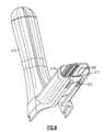
- FIG. 2is a front perspective view of a prior art disposable vaginal speculum used in the apparatus of FIG. 1 ;
- FIG. 3is a rear view of the prior art disposable vaginal speculum of FIG. 2 ;
- FIG. 4is a front perspective view of the prior art disposable vaginal speculum of FIGS. 2-3 ;
- FIG. 5is a partially unassembled rear perspective view of a vaginal speculum apparatus that is made in accordance with a first embodiment
- FIG. 6is a rear perspective view of the vaginal speculum apparatus of FIG. 5 , as assembled;
- FIG. 7is a front perspective view, partially unassembled, of the vaginal speculum apparatus of FIGS. 5 and 6 ;
- FIG. 7Ais a perspective view of a disposable sheath member used to cover a portion of the illumination assembly of the vaginal speculum apparatus of FIG. 7 ;
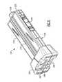
- FIG. 8is a side perspective view of an illumination assembly used in the vaginal speculum apparatus of FIGS. 5-7 ;
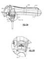
- FIG. 9is a bottom view, taken in perspective, of the vaginal speculum of the apparatus depicted in FIGS. 5-7 ;
- FIG. 10depicts a partial bottom end view of the vaginal speculum of FIGS. 5-7 ;
- FIG. 11is a bottom perspective view of the illumination assembly of FIG. 8 ;
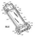
- FIG. 12is a perspective view of the illumination assembly of FIGS. 8 and 11 , with the cover removed;
- FIG. 13Adepicts the interchangeability of a corded illumination assembly relative to the vaginal speculum of FIGS. 5-7 ;
- FIG. 13Bdepicts an enlarged view of a portion of the apparatus depicted in FIG. 13A ;
- FIG. 14is a bottom perspective view of an alternative vaginal speculum design
- FIG. 15is a perspective view of a vaginal speculum apparatus including a cordless illumination assembly made in accordance with another embodiment
- FIG. 16depicts the vaginal speculum apparatus according to FIG. 15 , including a docking station;
- FIG. 17is a perspective view of a corded illumination assembly made in accordance with another embodiment.
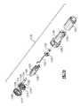
- FIG. 18is an exploded view of a vaginal speculum apparatus in accordance with another embodiment
- FIG. 19is an exploded view of a light cartridge used in the illumination assembly of the vaginal speculum apparatus of FIG. 18 ;
- FIG. 20is a rear perspective view of the vaginal speculum apparatus of FIG. 18 in an assembled condition
- FIG. 21is a side view of the disposable speculum and an illumination assembly of FIGS. 18-20 in an unassembled condition
- FIG. 22is a functional electrical block diagram of the illumination assembly of FIGS. 11 and 12 ;
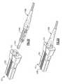
- FIG. 23is a side view of a vaginal speculum apparatus made in accordance with another embodiment, similar to that of FIGS. 16 and 17 ;
- FIG. 24is a side view of a vaginal speculum apparatus made in accordance with another embodiment
- FIG. 25is a perspective view of the distal end of the light pipe of the vaginal speculum that is depicted in FIGS. 5-7 ;
- FIG. 26is an enlarged view of a section of the bottom blade member of the vaginal speculum depicted in FIGS. 5-7 ;
- FIG. 27is a side cross sectional view of the light pipe of the vaginal speculum of FIGS. 5-7 ;
- FIG. 28is a partially unassembled view of a vaginal speculum apparatus manufactured in accordance with another embodiment
- FIG. 29is a top perspective view of an illumination assembly used in the vaginal speculum assembly of FIG. 28 ;
- FIG. 30is a side view of the vaginal speculum apparatus of FIGS. 28 and 29 , shown in one assembled condition;
- FIG. 31is a rear perspective view of the vaginal speculum apparatus of FIGS. 28 and 29 , shown in an alternative assembled position;
- FIGS. 32 and 33are perspective views of a speculum adapter as used with a corded illumination assembly in an unassembled and partially assembled condition.
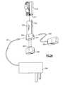
- FIG. 34is a diagrammatic view of alternative versions of power adapters used with the vaginal speculum apparatus of FIGS. 5-7 .
- FIGS. 1-4there is shown a prior art vaginal speculum apparatus 100 that includes a disposable speculum 102 and a reusable illumination assembly 140 .
- the disposable speculum 102includes three (3) interconnected components; namely, a lower or bottom blade member 104 , an upper or top blade member 108 , and a slide member 112 .
- Each of the two blade members 104 , 108is preferably made from a clear, durable plastic material, such as acrylic or polystyrene, wherein each of the lower blade member 104 and upper blade member 108 include a trough-shaped distal blade 116 .
- a handle portion 120extends vertically downward from the proximal or rear end of the lower blade member 104 , wherein the handle portion is integrally molded as part of the lower blade member.
- An intermediate portion of the slide member 112is fitted within a guide slot (not shown) that is provided on a rearward facing side of the handle portion 120 , the slide member further having a forked upper end or yoke 124 that receives the upper blade member 108 , which is pivotally attached thereto, including a downwardly extending lever portion 128 extending from the proximal end of the blade member.
- the lever portion 128further includes an opening 135 , shown only in FIG. 3 , defining a user aperture between the yoke 124 and the upper and lower blade members 108 , 104 .
- the lever portion 128terminates in a tab 137 , the latter having an interior slot 139 .
- the interior slot 139is engageable with a flexible rear extending projection 123 of the slide member 112 provided beneath the yoke 124 , and more particularly with a axially disposed set of ratchet teeth 125 that are provided on a lower facing surface of the projection.
- the ratchet teeth 125 of the flexible projection 123are biased into the interior slot 139 of the lever portion 128 of the upper blade member 108 .
- Angular articulation between the upper and lower blade members 108 , 104is initiated by applying finger pressure inwardly against the tab 137 , causing the lever portion 128 to move along the set of ratchet teeth 125 , and providing positive engagement therewith.
- the slide member 112further includes a lower tongue 129 having a single ratchet tooth 130 that engages with a set of corresponding teeth 131 that are provided on the rear exterior side of the handle portion 120 in order to provide relative vertical adjustment between the upper and lower blade members 104 , 108 , as needed. Additional details relating to the disposable speculum 100 depicted herein, including the adjustment of the upper and lower blade members 104 , 108 , can be found in U.S. Pat. No. 3,716,047, the entire contents of which are herein incorporated by reference.
- the handle portion 120 of the disposable speculum 100includes a receiving cavity 133 that is sized for receiving a housing 144 of the reusable illumination assembly 140 .
- the housing 144retains a miniature incandescent lamp, such as a halogen bulb, which is sealingly retained within a distal portion 148 thereof.
- a proximal portion of the housing 144 extending from the receiving cavity 133when assembled to the speculum 100 , includes a strain relief 152 extending to an electrical cable 156 that further extends to a switch assembly 160 . As shown in FIG.
- an electrical cable 164extends from the switch assembly 160 to a pronged plug 168 that engages a corresponding female plug 172 , the latter being tethered by a corresponding cable 174 extending to a power supply transformer 176 .
- the switch assembly 160is defined by an elastomeric housing, having a depressible button 163 that is used to selectively energize the miniature incandescent lamp (not shown) contained within the distal portion 148 of the illuminator housing 144 . Specific details relating to the illumination assembly 140 can be found in commonly assigned and co-pending U.S. Patent Application Publication No. 2004/0184288 A1, entitled: ILLUMINATION ASSEMBLY HAVING FLUID-TIGHT SEAL, the entire contents of which are herein incorporated by reference.
- a curved light tube or pipe 146is provided, the light pipe having a proximal end disposed in the upper end of the handle portion 120 of the lower blade member 104 , FIG. 2 .
- the contained miniature incandescent lampis optically coupled to the proximal end of the light pipe 146 .
- Emitted lightis then directed by means of internal reflection through the length of the light pipe 146 to a flat distal light-emitting end 147 wherein the light is then distributed substantially along a longitudinal axis of the lower blade member 104 towards the target.
- the light pipe 146is preferably molded directly into the lower blade member 104 , wherein the proximal end of the pipe, as noted, is provided in the upper end of the receiving cavity 133 of the handle portion 120 .
- light from the coupled incandescent lampis collected by means of a plastic lens (not shown in these figures, but one of which is depicted in FIG. 27 ) that is also preferably directly molded into the proximal end of the light pipe 146 .
- the lenshas an appropriate curvature to collect the light from the lamp of the illumination assembly 140 and conduct same through the transmissive light pipe 146 .
- the light pipe 146provides a coupling means for directing illumination from the contained miniature incandescent lamp of the illumination assembly 140 , there are a number of issues relating to the instrument design of FIGS. 1-4 .
- the design of the light pipe 146as clearly shown in FIGS. 2 and 3 , produces an obstruction for the user when viewed through the defined proximal opening 135 of the disposable speculum 100 .
- the reflective nature of the light pipe 146produces glare from light that is reflected proximally towards the user from the distal end 147 of the pipe, wherein losses in efficient light transfer detract from illumination of the target. Additional inefficiencies are created in that the light pipe 146 produces a shadow when external illumination is used.
- distal end 147 of the light pipe 146being flat and perpendicular to the centerline of the light pipe, produces a fluid-collection region that also blocks light from the target.
- a distal end 147 of the light pipe 146 as provided hereinalso produces difficulties in injection molding.
- the vaginal speculum apparatus 200includes a disposable speculum 204 and a illumination assembly 230 that is releasably attached to the handle portion 216 of the speculum.
- the handle portion 216is hollow, including an open bottom end extending into an otherwise enclosed receiving cavity 217 .
- the handle portion 216including the receiving cavity 217 , is defined by a substantially rectangular cross section, the significance of which is detailed below.
- the disposable speculum 204is generally defined by an upper or top blade member 212 , a lower or bottom blade member 214 (which integrally includes the handle portion 216 ), and a slide member 220 .
- Each of the upper blade member 212 and lower blade member 214are similarly constructed as described with regard to FIGS. 1-4 , wherein each member is preferably formed from a durable clear plastic material, such as acrylic or polystyrene, and in which each blade member is further defined by a trough-shaped elongate section or blade 215 , FIG. 7 .
- the upper blade member 212further includes a lever portion 224 extending downwardly at its proximal end thereof.
- the slide member 220also preferably being made from a durable plastic material, though not necessarily clear, further includes a forked upper portion or yoke 228 that pivotally receives the upper blade member 212 , as well as a flexible projection 225 that is disposed immediately beneath the yoke 228 and that extends rearward; that is, away from the handle portion 216 .
- the flexible projection 225is upwardly curved in a convex configuration (as depicted in FIG. 5 ), and includes a set of ratchet teeth 226 that are disposed along a bottom surface thereof.
- the lever portion 224is defined by a frame-like structure that includes an opening 221 , defining an aperture through which the user can examine the patient through the upper and lower blade members 212 , 214 , as well as a bottom tab 227 . Finger pressure on the bottom tab 227 allows the user to angularly articulate the speculum 200 , in a manner similar to that described previously.
- an intermediate portion of the slide member 220is movably (axially) disposed within a guide slot 223 extending over the entirety of the length of the rear side of the handle portion 216 .
- Finger pressure on the lower tongue 229 of the slide member 220permits engagement between a single tooth provided on the slide member 220 and a set of external teeth 222 provided on the proximal or rear side of the handle portion 216 and enables selective vertical articulation (spacing) of the lower blade member 214 with respect to the upper blade member 212 through selective movement of the slide member 220 and yoke 228 .
- the guide slot 223extends axially through the set of external teeth 222 , improving moldability as opposed to the version shown in FIG. 1 .
- the receiving cavity 217 of the herein described disposable speculum 204is sized to interchangeably and releasably accommodate at least two illumination assemblies.
- the illumination assemblies that can be interchangeably accommodated by the speculumcan vary based on at least one structural and/or functional aspect, including size, type of power supply, and type of light source.
- the receiving cavity 217 of the speculum 204can interchangeably receive either a corded illumination assembly 140 , FIG. 1 , and similarly constructed assemblies utilizing a non-portable power supply (e.g., an AC power supply) or a portable illumination assembly such as, for example, the exemplary assembly 230 more completely shown in FIGS. 8 , 11 and 12 . Details relating to this exemplary version are now provided.
- the cordless or portable illumination assembly 230is at least partially depicted in each of FIGS. 5-8 , 11 and 12 .
- this illumination assembly 230is defined by a housing 236 having a substantially hollow interior that is sized to retain a number of components, as described below.
- the housing 236is defined by a lower base portion 260 and a narrower extending upper portion 245 .
- the two portions 245 , 260are integrally formed by molding the housing, the housing being made from a durable plastic material.
- the narrower extending upper portion 245is sized to fit entirely within the receiving cavity 217 of the handle portion 216 and includes a short tubular open-ended extending portion 238 projecting from a top surface 235 thereof.
- the upper portion 245 of the housing 236also includes a set of parallel guide rails 249 (only one of which is shown in each of FIGS. 8 and 11 ) disposed along opposite sides of the housing that are used to align the assembly 230 with respect to the receiving cavity 217 of the speculum 204 , permitting the assembly to be fitted within the cavity in two rotational orientations, 180 degrees spaced from one another, as described in greater detail below.
- the tubular open-ended projecting portion 238includes a spacer tube 241 .
- a lens 259is fitted to a distal end of the spacer tube 241 .
- the lens 259according to this embodiment, has a plano-convex configuration and is recessed within the tubular extending portion 238 . This lens 259 is used to more efficiently direct illumination from a coupled light source to a light pipe 254 , FIG. 27 , described in greater detail in a later section.
- the light sourceis a miniature white LED 232 , shown schematically in FIG. 22 , such as a Model LXHL-PW01 white LED manufactured by Lumileds, Inc.
- the LED 232includes a domed transparent envelope (not shown) at its upper end that is aligned with the lens 259 to provide optical coupling therewith.
- the interior of the spacer tube 241provides a surface that acts to direct stray light emitted from the envelope of the LED 232 and directs this light toward the lens 259 .
- the light sourcecan be a miniature incandescent lamp, such as, for example, a halogen bulb, arc lamp, or other suitable form of light source.
- a single light sourceis depicted herein, multiple sources could be disposed within the housing 236 , such as, for example, an array of LEDs having different colors (e.g., blue, green, white) to provide the cumulative effect of a “red” free filter.
- a lower portion of the LED 232is retained within a heat sink 244 made from a heat conductive material, such as, for example, aluminum, into which the lower end of the spacer tube 241 extends, as well as the extending electrical contact wires (not shown) from the LED 232 .
- the heat sink 244extends substantially across the width of the extending upper portion 245 of the housing 236 , with the exception of a recessed portion 272 that accommodates an inner walled cavity 276 .
- the illumination assemblyfurther retains at least one battery 242 , in this instance, a single rechargeable lithium ion battery, such as a Model UF 812248P JFH battery, manufactured by Sanyo Corp, the battery being disposed in a compartment defined by a pair of tabs 280 for retaining the lower end of the battery.
- the upper end of the battery 242is retained, according to this embodiment, against a portion of an inner wall defining the inner walled cavity 276 , the latter being defined to receive a spring loaded plunger 284 beneath the heat sink 244 , the plunger being aligned for movement in a direction that is perpendicular to the primary axis of the illumination assembly 230 .
- a printed circuit board 240 that includes components and circuitry for powering the LED 232is disposed within the base portion 260 of the assembly housing 236 according to this embodiment.
- the circuit board 240includes circuits for controlling the current required by the LED 232 .
- the circuit board 240includes a buck-boost constant current LED driver 251 , such as a Model LTC3453EUF, used for this purpose.
- the circuit board 240is retained and aligned within the housing 236 using a set of guide rails 285 , though other suitable retaining means can be used.
- a set of charging contacts 286are disposed immediately beneath the circuit board 240 , each projecting through a bottom surface 287 of the housing 236 .
- each of the contactsbeing equally spaced from one another, the purposes of which are detailed below.
- the wires extending from the lower portion of the LED 232 and extending through the heat sinkare passed behind the battery 242 to the circuit board 240 and are connected therewith in a conventional manner, while wires extend from the circuit board 240 to the negative terminal of the battery 242 .
- the battery 242is rechargeable wherein the housing 236 is sized and configured to permit recharging by attachment to a docking station. Details relating to the attachment of a housing of an illumination assembly is described in a subsequent embodiment, but for purposes of this discussion and referring back to FIGS. 11 and 12 , the charging contacts 286 are engaged when the base portion 260 of the housing 236 is placed within a port of the docking station, the port being configured to retain same. The contacts 286 are engaged with the lower surface of the circuit board 240 to permit recharging of the contained battery 242 , the latter being electrically connected to the circuit board.
- the three charging contacts 286enable the housing 236 to be installed in at least two 180 degree-spaced orientations within a slot of the docking station and still enable recharging, the contacts therefore being position insensitive.
- the circuit board 240further includes a short circuit/over current protection device 247 to prevent shorting and overcharging of the battery 242 .
- a Model UCC3952PW-1 manufactured by Texas Instruments, Inc.is used, though other suitable devices can be substituted.
- the base portion 260further includes a pair of clamping recesses 289 , FIG. 11 , that are used in conjunction with the charging contacts 286 to allow a “clothespin” mechanism (not shown) to engage therewith for charging or for auxiliary power, as needed.
- the housing 236can be configured alternatively to accommodate a plug-in cord 291 to a non-portable (e.g., AC) power supply by means of a transformer 296 in lieu of charging the battery 242 , or when the battery is nearly or fully depleted as indicated by a low battery power indicator 295 provided on the exterior of the housing 236 .
- the low-battery power indicator 295is provided adjacent the top of the upper portion 245 of the housing 236 , but could be otherwise disposed such as along the bottom surface 287 , FIG.
- the indicatorbeing connected in a conventional manner to the circuit board 240 , as shown schematically in FIG. 22 .
- the battery 242FIG. 12
- the at least one battery 242could be alternatively and separately contained within a power adapter 298 that is either tethered to the assembly housing 236 , such as by means of a cable 293 that can plugged into a receptacle 297 in the base portion 260 or a power adapter 288 having a contained battery (not shown) that is mechanically engaged to the bottom surface 287 , FIG. 12 , of the base portion 260 , such as using a set of pins 299 for engaging the charging contacts 286 .
- a conductive strip member 290extends along an interior side wall of the housing 236 , the strip member having a lower end 292 that is disposed adjacent to conductive contacts 243 of the circuit board 240 .
- the conductive strip member 290extends into the upper extending portion 245 to switch contacts 294 that are disposed on the interior side of a mechanical slider switch 248 , the switch being disposed on the exterior of the housing 236 , as shown most clearly in FIGS. 11 and 12 .
- the switch 248is configured, according to this embodiment, to permit automatic operation when the housing 236 is disposed at least a predetermined distance into the receiving cavity 217 of the handle portion 216 , such as through engagement between an internal feature within the receiving cavity 217 and the exterior surface of the switch 248 .
- the spring-loaded plunger 284is used in conjunction with the interior wall of the receiving cavity 217 to assist in engagement and in retaining the illumination assembly 230 in the receiving cavity 217 .
- the exterior surface of the slider switch 248includes a pair of external projections 253 , one on each of the upper and lower end of the slider switch to aid in manual operation of the assembly.
- engagementcauses the switch 248 to move downwardly against the bias of a coil spring (not shown), biasing the switch in an Off position, and causes the lower end 292 of the conductive strip member 290 to electrically contact the conductive contacts 243 of the circuit board 240 , thereby completing the circuit and causing the LED 232 to energize.
- the illumination assembly 230further permits the slider switch 248 to manually be preset to a locked position, in which the LED 232 can be energized prior to installing the assembly 230 into the receiving cavity 217 , FIG. 5 , of the speculum 204 , FIG. 5 .
- the slider switch 248remains in the locked position based on the downward engagement of the switch 248 by finger pressure against one of the external projections 253 that locates a detent pin 261 attached to a leaf spring 263 . Finger pressure of the switch 248 enables de-energization of the LED 232 , but no automatic operation when the illumination assembly 230 is locked, irrespective of the position of the housing 236 within the receiving cavity 217 , FIG. 5 .
- switch 248when not placed in the “locked” position, removal of the housing 236 from the receiving cavity 217 causes the switch 248 to be automatically de-energized (e.g., by sliding the switch 248 upward to the original position, moving the lower end 292 of the conductive strip member 290 out of contact with the circuit board 240 ) and thereby de-energizing the contained light source (e.g., LED) 232 .
- the contained light sourcee.g., LED
- other forms of switch assembliessuch as, but not limited to optical switches, magnetic/reed switches, and other mechanical switches (such as an ON/OFF throw switch that can be enabled with the speculum when engaged therewith to automatically or manually energize and de-energize the contained LED) can be utilized.
- the cordless, self-contained and compact nature of the herein described illumination assembly 230 as well as the operation, including the locking feature of the exterior slider switch 248further enable the herein described assembly to be useful independently as an examination light.
- the positioning of the LED 232 within the spacer tube 241 as well as the positioning of the collecting lens 259permit illumination to be directly efficiently and uniformly emitted.
- the positioning of the contained LED 232 within the illumination assembly 230 and particularly within the heat sink 244further provides a safety feature in that the exposed end of the tubular portion 238 can be brought into substantial contact with a patient without particular risk of injury. More specifically, because the coupled lens is interior to the tubular extending portion 238 , the lens 259 cannot be readily contacted by a patient or user.
- the lens 259is further isolated from shock loads if the illumination assembly 230 is dropped.
- the receiving cavity 217 of the herein described vaginal speculum 204further permits the releasable attachment of a corded illumination assembly 140 , as previously depicted and shown with regard to FIG. 1 .
- the receiving cavity 217includes a pair of opposed interior rail-like portions 250 that are formed between two substantially interior parallel sidewalls of the handle portion 216 , the rail portions extending along substantially the length of the receiving cavity 217 that that are used to support and align the corded illumination assembly 140 .
- the rail-like portions 250are also used to align with the guide rails 249 , FIG. 8 , of the cordless illumination assembly 230 , according to this embodiment in which the assembly can be mounted in at least two 180 degree spaced orientations.
- the upper portion of either illumination assembly housing 236 , 144 , including the extending tubular open-ended portion 238 of the housing 236 or the distal portion 148 , FIG. 1 , of the illumination housing 144 , FIG. 1is received in the receiving cavity 217 .
- a pair of oppositely disposed internal centering fingers 246form a guide in order to center the distal portion 148 , FIG. 1 , of the corded illumination assembly 140 , FIG. 1 , within the receiving cavity 217 in either of the two 180 spaced orientations.
- Lateral spring-like protrusions 136 , FIG. 1disposed on the exterior of the illumination housing 144 , FIG. 1 , initially guide and orient the illumination assembly 140 , FIG. 1 , within the receiving cavity 133 , FIG. 1 .
- the protrusions 136 , FIG. 1also provide a securing function through a friction fit with the interior of the receiving cavity 133 , FIG. 1 .
- the corded illumination assembly 140 and the cordless or portable illumination assembly 230can be installed into the receiving cavity 217 of the handle portion 216 in which the light source contained in each assembly is effectively coupled with the proximal end of a light pipe 254 , FIG. 27 , to uniformly illuminate the target.
- the lightis directed from the contained LED 232 , in part using the reflective interior surface of the spacer tube 241 to the lens 259 that collects the light and then directs this light to a collecting lens 262 , FIG. 27 , as described below.
- the upper portion 245 of the housing 236is sized to fit entirely within the receiving cavity 217 , wherein the handle portion 216 is defined by an aspect (width ⁇ depth) ratio of approximately 2:1 that substantially matches that of the upper portion 245 , thereby defining a substantially close-contacting fit.
- a range of 1.25:1 to 3:1is suitable to provide adequate stability and greater rigidity, while permitting effective hand held operation.
- the extending base portion 260 of the illumination assembly 230further defines an effective length or working length, as measured from a point P, FIG. 6 , to the bottom end of the base portion 260 of 5.50 inches, as shown in FIG. 6 by “A”.
- point Pis representative of the most proximal part of the speculum 204 typically in contact with a patient for purposes of examination and is located on the exterior underside of the lower blade member 214 along the elongate blade portion 215 , FIG. 7 , thereof, this point as noted being representative. More particularly, the point P is substantially located in the vicinity of the distal end of the light pipe 254 , FIG. 27 .
- a preferred range for “A”lies between approximately 3 inches to approximately 6 inches, according to this embodiment.
- the substantially rectangular end of the base portion 260provides a stable base for the user as well as effective rigidity, wherein the apparatus 200 , FIG. 5 , can easily be hand-held.
- the herein described speculum 204includes a light pipe 254 having a proximal end 255 , which is coupled to the light source of any of the interchangeably attached illumination assemblies 140 and 230 .
- the proximal end 255further includes a collecting lens 262 .
- the lens 262is molded as an inset in relation to the proximal end by means of a pedestal section 264 centered within an annular gap 265 formed between the set of internal centering fingers 246 .
- the pedestal section 264is reinforced within the annular gap 265 by at least one web (not shown) to prevent sagging.
- the collecting lens 262by virtue of this construction provides improved optical coupling with the light source of either illumination assembly 140 , FIG. 1 , 230 , FIG. 7 .
- This improved optical couplingresults from improved mechanical alignment of the illumination assembly with the lens 262 , FIG. 27 , and from more effective internal reflection at the cylindrical portion of the light pipe 254 in the annular gap 265 .
- the distal end 258 of the light pipe 254is also different than the version of FIG. 2 .
- the distal end 258is preferably molded into the lower blade member 214 and has a contoured configuration.
- contouredit is meant that the surface of the distal end 258 has a defined shape that is not a 90 degree cut with respect to the axis of the light pipe 254 . Therefore, it is intended that this term can cover both a range of angled surfaces as well as curvi-linear surfaces, such as spherical, parabolic and the like.
- the contour at the distal end 258is preferably formed as a scallop, such as would be cut by means of an end mill or similar apparatus.
- the above modificationcan be placed into the molding process for the lower blade member 214 of the speculum 204 , for example, if the speculum is being made from polystyrene, acrylic or similar materials. It will be readily apparent that the concept should not be restricted to these materials, but should also be applied to literally any light transmissive material.
- the contour provided in the distal light emitting end 258is essentially a scalloped cut producing an inwardly (i.e., concave) curved portion having a radius of approximately 1.5 to 3.5 inches.
- the center of the radiusis provided from a point Q, FIG. 27 , that is approximately 2.6 inches as measured distally from the rear side of the handle portion 210 and approximately 2.4 inches, as measured vertically from the top of the trough 215 , FIG. 7 , of the lower blade member 214 .
- These dimensionsare shown in FIG. 27 . It is noted that both dimensions locating point Q can be varied by approximately +/ ⁇ 0.30 inches and still produce a desirable effect.
- the herein defined distal end 258can alternatively be formed using an angled cut approximating that of the radiused scallop end described above.
- a suitable angle of approximately 70 degrees, as measured clockwise from the proximal upper end of the cut with respect to the perpendicularis provided, thereby creating a downwardly extending face.
- the anglecan vary from approximately 55 degrees to approximately 80 degrees for purposes of providing improved illumination spot quality while still reducing glare to the user. Illumination is passed through the entirety of the distal face such that fluid buildup will not significantly interfere with light transmission.
- the distal end 258can be provided with a series of stepped surfaces (not shown).
- the light emitted from the coupled illumination assembly 140 , 230is collected by the lens 262 , FIG. 27 , as positioned on the pedestal section 264 , is reflected internally within the light pipe 254 and then is emitted from the distal end 258 .
- the emission of the lightis such that the light is directed towards the distal end of the elongate blade portion 215 , FIG. 7 , wherein significant light is not reflected back to the user viewing through the aperture or opening 221 , FIG. 5 .
- surfaces proximal to the light pipe 254 of the upper and lower blade members 212 , 214can be treated (e.g., as by frosting). Such treatment assists in reducing unwanted light (that is, light other than that received from the target) from being directed toward the user when the speculum 204 is used with an external light source.
- the distal end 258 of the light pipe 254can be provided with a variety of different optical surfaces through treatment thereof to smooth light output and control the distribution of illumination.
- FIG. 14depicts an alternative design in which the receiving cavity 217 A of a disposable speculum can be modified to accommodate a cordless illumination assembly (not shown) having a housing (not shown) that is configured to two AAAA batteries in side by side fashion.
- a set of rails 250 Aare sized to separately accommodate the corded illumination housing, wherein the rails align the assembly as well as retain the assembly in the receiving cavity 217 A.
- the handle portion 216 , FIG. 5 , 216 A, FIG. 14can further include a series of parallel vertically arranged ribs 256 , FIG.
- the ribsproviding a means for dissipating heat developed by the retained illumination assembly, as well as providing a means for keeping a user's fingers away from “hot” surfaces. It has been determined that the provision of four (4) vertically extending exterior ribs 256 , each having a depth of about 0.160 inches, a thickness of about 0.055 inches and having an equal spacing of about 0.150 inches provides additional protection. Other shapes can also be utilized.
- At least one air gapis also developed, FIG. 13 , in the receiving cavity 217 based on the size differential between the receiving cavity and the corded illumination assembly 140 , the at least one air gap being used to channel heat away from the illumination assembly 140 or an alternative illumination assembly 140 A, shown in FIG. 17 and described in greater detail below, that can include an LED as a light source in lieu of an incandescent lamp.
- the housing 236could at least partially contain a phase-change material (PCM), such as, for example, those manufactured by TEAP Energy in which residual heat developed or generated by the assembly is essentially stored during use and then later dissipated after use of the apparatus some later time after the illumination assembly has been deactivated.
- PCMphase-change material
- a speculum adapter 281can be used to facilitate attachment of a corded illumination assembly 140 B, to the receiving cavity 217 of the speculum 204 .
- the speculum adapter 281according to the embodiment is a plastic-molded body that includes an external envelope 282 that is shaped essentially like that of housing 236 .
- the speculum adapter 281further includes an internal envelope 283 that is adapted in this instance to accommodate the housing 144 B of a corded illumination assembly 140 B containing a light source, such as an incandescent lamp or at least one LED (not shown).
- the speculum adapter 281assumes a friction or snap fit or other substantial close contact with the interior of the receiving cavity 217 .
- the internal envelope 283 of the adapter 281retains the illumination assembly 140 B without requiring predetermined alignment and enables optical coupling with the proximal end of the light pipe 254 , FIG. 27 .
- the speculum adapter 281is disposed in one of two 180 degree orientations within the receiving cavity (not shown in this view) and the illumination assembly 140 B is fitted into the internal envelope 283 , either prior to placing the adapter 281 into the receiving cavity or afterward.
- the adapter 281is sized such that the distal portion 148 B of the assembly extends therethrough following assembly, allowing the contained light source to be optically coupled with the light pipe (not shown in this view).
- the adapter bodyprovides a means for dissipating heat developed by the contained illumination assembly wherein at least a portion of the adapter 281 could also further be made from a phase change material (PCM), such as those previously noted.
- PCMphase change material
- the herein described speculum apparatus 200is more versatile and can be used, for example, with bed-ridden patients based in part on the fact that there is no corded portion extending from the handle portion 216 , 216 A.
- the herein described illumination apparatushas an effective working distance A, FIG. 6 , of approximately 3 to 6 inches that provides increased versatility and utility with regard to patients on a bed or examination table. As such, there are no issues such as those that are previously encountered with cabled or tethered assemblies.
- Either illumination assembly 140 , 230can be easily reused by removing same from the receiving cavity 217 , 217 A of the handle portion 216 , 216 A after an examination and discarding the speculum 204 .
- the corded illumination assembly 140 , FIG. 1can be covered prior to use with a disposable sheath.
- An exemplary version of such a sheathis described in U.S. Patent Application Publication No. 2004/0186355 A1, entitled: PROTECTIVE SHEATH FOR ILLUMINATION ASSEMBLY OF A DISPOSABLE VAGINAL SPECULUM, the entire contents of which are herein incorporated by reference.
- a portion of an exemplary sheath assembly 1624 for this purposeis also depicted in FIG.
- the sheath assembly 1624includes a spool or ring member. This sheath assembly can be used in connection with the cordless illumination assembly or alternative sheath assembly designs can be used. As shown in FIGS. 7 and 7A , the extending base portion 260 of the illumination assembly 230 , on the other hand, can be covered using a flexible sheath member 266 in substantial sealing relation.
- the sheath member 266need only conform to the base portion 260 since the remainder of the illumination assembly 230 is contained within the receiving cavity 217 , wherein the sheath can be removed for disposal using a tab 268 that permits tearing of a disposed frangible tear strip 270 .
- FIGS. 15 and 16there is shown a vaginal speculum apparatus 378 made in accordance with another embodiment.
- the disposable speculum 102 of the apparatusis literally identical in construction to that depicted according to FIG. 1 .
- the disposable speculum 102includes a lower blade member 104 having an integral handle portion 120 that includes a receiving cavity 133 formed therein.
- an illumination housing 144as shown in FIGS. 1-4 , but not shown in FIGS. 15 and 16 , such as the 78810 model illuminator manufactured by Welch Allyn, Inc., can be releasably fitted into the receiving cavity of the handle portion 120 for coupling to the distal end of a contained light pipe.
- a cordless illumination assembly in accordance with this embodimentcan also be interchangeably attached into the receiving cavity 133 of the handle portion 120 of the speculum 102 without requiring modification to the speculum.
- a corded illumination assembly housing and the cordless illumination assemblycan be interchangeably fitted into the receiving cavity 133 defined by the handle portion 120 of the speculum 102 of FIGS. 15-16 according to this embodiment.
- the cordless illumination assembly 380is defined by a housing 384 wherein at least one extremely compact battery 404 is disposed in a lower or proximal end 388 of the housing.
- the at least one compact battery 404may be a AAAA rechargeable battery, such as that available from Sanyo Corp (AAAA Size 1.2 Volt 300 mAh NiMH rechargeable battery). Other suitable miniature batteries can also be substituted.
- a miniature light sourcein this case, a miniature LED (not shown but similar to that previously described as 232 , FIG. 22 ), such as a Model LXHL-PW01 white LED manufactured by Lumileds, Inc.
- the at least one battery 404is of the NiMH type, a circuit external to the battery may be needed in order to provide the correct current to the LED 232 , FIG. 22 .
- the circuit external to the battery 404could be a constant current circuit set to deliver the current required by the LED 232 , FIG. 22 , similar to that previously depicted in FIG. 22 .
- the NiMH battery described hereintypically operates at 1.2 volts and the LED 232 , FIG. 22 , operates at 3.7 volts. Consequently, if fewer than three (3) NiMH batteries are used, the circuit to the battery 404 would be a voltage booster circuit.
- the illumination assembly 380further includes circuitry 400 , enabling the voltage of the at least one contained battery 404 to be raised, if necessary, to that required by the LED 232 , FIG. 22 .
- the voltage required to power the LED 232 , FIG. 22is about 3.7 volts.
- the LED described hereinis rated at 1 Watt, has a light output of at least 20 lumens/watt and has a minimum service life of at least 1000 hours.
- An exemplary circuit for performing this function of permitting batteries to be electrically adaptedis more fully described in U.S. Patent Application Publication No.
- a heat sink 396 provided in the illumination assembly housing 384permits the heat generated by the LED 232 , FIG. 22 , and attendant circuitry 400 to be effectively dissipated.
- the illumination assembly housing 384is sized, owing to the size of the at least one battery 404 and the LED, to be fitted within the receiving cavity 133 of the handle portion 120 of the speculum 102 without any modification thereto and in which the components are arranged such that the proximal end 388 of the assembly housing 384 extends only marginally from the handle portion 120 when the illumination assembly housing 384 is inserted therein.
- the LEDis optically coupled by means of lenses 392 (shown only in FIG. 16) and 262 , FIG. 27 , relative to the proximal end of a light pipe 254 , such as previously described, or to an existing light pipe 146 , FIG. 2 .
- the working life of the compact battery 404 described hereinis relatively limited.
- the apparatusis configured such that the battery is designed to operate over a life extending at least equivalent to that of a day of examinations.
- a recharging or docking station 408is provided, the station being connectable to an AC power supply (not shown) and including a number of receiving slots that define corresponding charging sockets 412 .
- Each of the charging sockets 412is sized for receiving the proximal end 388 of the illumination assembly housing 384 .
- the lower extending or proximal end 388 of the illumination assembly housing 384includes either sealed circuitry for charging a sealed inductive charge circuit (not shown) or contacts that are engaged by a pinned or other suitable connection with the recharging sockets 412 , such as charging contacts 286 , FIG. 12 .
- Multiple recharging sockets 412are provided, thereby permitting multiple illumination assemblies 380 to be stored and simultaneously charged for use in the herein described vaginal speculum apparatus 378 .
- the docking station 408can further include at least one charge level indicator to indicate when charging is complete.
- a similar docking stationcan be configured for use with any of the cordless or portable illumination assemblies described herein depending, for example, on the geometry thereof.
- the corded illumination assembly 140 of FIG. 1can also be reconfigured to provide an alternative LED light source in lieu of an incandescent lamp.
- the overall construction of a corded illuminator assembly 140 Ais similar and therefore the same reference numerals are used where applicable.
- An LED 232 , FIG. 22such as the Model DCHL-PW01 white LED manufactured by Lumileds, Inc. is disposed in a distal portion 148 A of a housing 144 A.
- the housing 22includes a domed transparent envelope (not shown) that extends from the distal portion 148 A for optically coupling with the proximal end of a light pipe (not shown in this figure) disposed within the handle of a vaginal speculum, as previously described.
- the housing 144 Ais appropriately sized to be fitted within the receiving cavity 133 , FIG. 1 , defined by the handle portion 120 , FIG. 1 , of the speculum 102 , FIG. 1 , in a similar manner to that of the assembly shown in FIG. 1 .
- the inclusion of the LEDin lieu of a contained incandescent lamp provides a number of advantages; for example, increased working life, less heat generation, improved color rendering and less power consumption. As shown in FIG. 17 and similar to FIG.
- a proximal portion of the illumination assembly housing 144 Aincludes a strain relief 152 extending to an electrical cable 156 that further extends to a switch assembly 160 .
- An electrical cable 164extends from the switch assembly 160 to a pronged plug that engages a corresponding female plug 172 , the latter being tethered by a corresponding cable 174 extending to a power supply 176 .
- the switch assembly 160is defined by an elastomeric housing, having a depressible button 163 that is used to selectively energize the contained LED 232 , FIG. 22 , within the distal portion 148 A of the illumination assembly housing 144 A.
- each of the corded or tethered illumination assemblies 140 , 140 A or cordless illumination assembly 380can be disposed interchangeably within the receiving cavity 133 of the disposable speculum 102 and coupled with the proximal end of the light pipe 146 wherein illumination is conducted through the light pipe by internal reflection to the distal end 147 towards the target.
- the housing 384can be configured with a switch member to enable automatic energization of the contained light source when the housing is disposed at least a predetermined distance into the receiving cavity 133 through engagement with at least one feature on either the housing and/or the interior of the receiving cavity.
- the speculum apparatus 1200includes a disposable speculum 1204 as well as an illumination assembly 1260 that is releasably attached to the speculum.
- the speculum 1204is configured to permit interchangeable attachment of either a corded illumination assembly such as 140 , FIG. 1 , or a cordless (portable) illumination assembly 1260 .
- a corded illumination assemblysuch as 140 , FIG. 1
- a cordless (portable) illumination assembly 1260For purposes of this embodiment, only the cordless illumination assembly 1260 is herein discussed in detail.
- the disposable speculum 1204is defined by an upper or top blade member 1212 , a lower blade member 1214 that includes an integral handle portion 1216 , and a slide member 1220 .
- Each of the top blade member 1212 and lower blade member 1214are similarly constructed as that shown in FIGS. 1-4 and are formed from a durable clear plastic material, such as an acrylic or polystyrene, wherein each blade is defined as a trough-shaped elongate member.
- the top blade member 1212further includes a downwardly extending lever portion 1222 at the proximal end thereof.
- the slide member 1220also made from a plastic material, further includes a forked upper portion or yoke 1226 that pivotally receives the lever portion 1222 of the top blade member 1212 .
- the handle portion 1216does not include either a light collecting lens or a light pipe, as previously required. Rather, the upper portion of the interior of the handle portion 1216 is open.
- a substantially cylindrical receptacle 1234Distally adjacent and part of the handle portion 1216 and disposed beneath the lower blade member 1214 and extending essentially vertically therebeneath, is a substantially cylindrical receptacle 1234 having an open end 1238 and a defined hollow interior that is sized for retaining the illumination assembly 1260 of the herein described apparatus 1200 , as described in greater detail below. It should be readily understood, however, that other geometries can be substituted.
- the receptacle 1234includes an upper portion 1242 , shown only in FIG. 21 , which according to this embodiment is opaque or black, and a lower portion 1246 which is made from a clear material, such as that of the lower blade member, the lower portion including the open end 1238 .
- the receptacle 1234is attached through an opening formed in the lower blade member 1214 through which the upper portion 1242 partially extends therethrough, or otherwise the receptacle can be integrally molded so as to form a portion of the lower blade member.
- the handle portion 1216can be modified (e.g., widened—not shown) in order to accept the illumination assembly 1260 .
- the illumination assembly 1260is defined by a hollow casing or housing 1264 sized to accommodate a number of components, including a prismatic member 1268 that is mounted to an upper portion 1269 thereof.
- the casing 1264retains a miniature light source, which according to this embodiment is a miniature LED 1272 , FIG. 19 , such as a Model LXHL-PW01 white LED, manufactured by Lumileds, Inc.
- the light sourcecan be a miniature incandescent lamp, such as a halogen bulb, an arc lamp, or other form of suitable light source.
- different LEDscan be substituted, such as, for example, an array of different colored LEDs (e.g., blue, green) can be provided in the housing and configured in order to produce in combination a “red-free” filter.
- the miniature LED 1272is retained within a cartridge 1276 .
- a rechargeable or other battery 1280is disposed within the casing 1264 beneath the cartridge 1276 , wherein a metallic conductive strip member 1284 is placed within the interior of the casing along the exterior of the battery and the cartridge to complete the circuit.
- the battery 1280is retained by a spring 1288 disposed at the lower or negative end of the battery, the casing having an end cap 1292 for releasably retaining the above components.
- a condensing lens 1286is provided between the prismatic member 1268 and the cartridge 1276 , for collecting and uniformly distributing light output of the miniature LED 1272 through the prismatic member, which includes a mirrored upper surface such that the light output is directed between the two blade members 1212 , 1214 .
- the lens 1286 according to this embodimentis plano-convex.
- the cartridge 1276includes a cylindrical housing body 1304 which, according to this embodiment, is made from Radel R, polyphenylsulfone or other suitable polymer. Alternatively, the body 1304 can be fabricated from literally any electrical insulating material, wherein the miniature LED 1272 (only partially shown in FIG. 19 ) is disposed at a distal end 1306 adjacent a reflector cap portion 1310 that is attached in overlaying relation thereto.
- PCBprinted circuit board
- the PCB 1314is disposed immediately below or proximal to the miniature LED 1272 , and includes an opening 1322 for receiving the projecting portion 1326 of a heat sink 1330 , retained by the housing body 1304 in order to dissipate heat that is generated by the miniature LED 1272 , as well as heat also generated by the PCB 1314 .
- the heat sink 1330includes an axial groove 1327 extending over the entire axial length thereof and is sized to retain one of a pair of electrical contacts.
- a first electrical contact 1329extends from the proximal side of the printed circuit board 1314 and includes a lead wire and a strip member 1334 .
- the strip member 1334 of this electrical contact 1329when finally assembled, is sandwiched between a cartridge collar 1333 and the exterior of the cartridge body 1304 .
- a second electrical contact 1331is formed from a lead wire that extends axially from a battery contact board 1335 , the board being retained within the bottom of the cartridge body 1304 .
- the first electrical contact 1329is a negative electrical contact while the second electrical contact 1331 is a positive electrical contact in which the positive terminal of the battery 1280 , FIG. 18 , is contacted by a rivet 1337 that is disposed within a chamfered hole 1339 at the bottom of the cartridge body 1304 .
- the reflector cap portion 1310is defined by a through opening 1336 that is fitted about the lens envelope of the miniature LED 1272 , the through opening according to one embodiment having an inwardly tapered surface 1338 that is used in order to effectively focus the light emitted from the miniature LED 1272 onto the condensing lens 1286 , FIG. 18 , which is fitted between the prismatic member 1268 and the LED 1272 .
- the reflector cap portion 1310according to this embodiment also recesses the LED lens and protects the lens from damage, such as from dropping the cartridge 1276 , when removed from the illumination assembly casing 1264 for cleaning.
- the cartridge 1276is entirely portable and modular and therefore, for example, other LEDs or light sources could be substituted in the herein described illumination assembly by simple substitution of another cartridge having a different light source.
- a negative electrical contactis created as the battery 1280 is pushed axially against the contact spring 1288 by means of a rotary switch assembly (not shown).
- the strip 1334 of the electrical contact 1329contacts the cartridge collar 1333 wherein the contact board 1335 within the cartridge body 1304 contacts the positive battery terminal, completing the circuit, and energizing the LED 1272 .
- each of the preceding handle portionscan include a feature, such as a groove or slot, which permits manual engagement by a user of an exterior switch member, such as 248 , FIG. 12 .
- the illumination assembly 1260is releasably attached to the cylindrical receptacle 1234 of the disposable speculum 1204 such that the prismatic member 1268 is placed into the upper portion 1242 , FIGS. 20 , 21 , of the receptacle extending into the opening provided between the two blade members 1212 , 1214 , wherein the upper portion of the lower blade member 1214 has a distal facing opening (not shown).
- the light emitting surface of the prismatic member 1268is directed axially towards the opening between the top and lower blade members 1212 , 1214 .
- the casing 1264is accommodated by means of a friction or interference fit with the interior walls of the receptacle 1234 , although other suitable releasable retention schemes, such as snap-fitting, can be used.
- the present illumination assembly 1260eliminates the need to mold or otherwise provide a light pipe or a similar light coupling means in the lower blade member 1214 , such as provided in FIGS. 2-4 .
- the illumination assembly 1260is battery powered, no cabling is required. Therefore, the herein described apparatus becomes more versatile, for example, permitting use for bed-ridden patients preventing entanglement with the clinician or patient, and preventing the risk of cross-contamination due to dirt collecting on cables.
- the batteriesare rechargeable and the illumination assembly can be placed within a docking station, such as depicted in FIG. 16 , to enable recharging.
- a vaginal speculum apparatus 1600includes a self-contained illumination assembly 1608 that is provided within the handle portion 120 of a disposable speculum 102 .
- the illumination assembly 1608comprises a housing 1612 that includes a miniature light source 1614 , such as a white or other LED, as previously described, wherein the output of the contained light source is coupled to a light collecting lens 1616 and to a light pipe 1620 of the speculum 102 similar to that of FIGS. 16 and 17 .
- the handle portion 120 of the speculum 102includes a slot 134 , FIG. 1 , adjacent the receiving cavity 133 that accommodates a disposable sheath assembly 1624 .
- the disposable sheath assembly 1624includes a spool or ring member 1628 that is attached to the slot 134 , the spool member having an opening that permits passage of the illumination assembly therethrough.
- the spool or ring memberfurther retains a thin flexible transparent sheath 1632 that is folded onto the exterior of the spool member for deployment thereof to cover the illumination assembly 1608 , as needed.
- An exemplary version of such a sheath assembly 1624 and its interconnection to a disposable speculumare each described in U.S. Patent Application Publication No. 2004/0186355 A1, previously incorporated by reference in its entirety.
- FIG. 24Yet another embodiment of a vaginal speculum apparatus 1700 is shown according to FIG. 24 .
- This particular apparatus 1700includes an illumination assembly 1708 defined by an housing 1712 that is sized to be fitted into a receiving cavity of a handle portion 1216 of a disposable speculum 1204 .
- the housing 1712according to this embodiment contains a power supply, such as at least one contained battery, as well as circuitry for powering a light source, such as at least one LED 1716 .
- the LED 1716is externally disposed along a surface of the trough-shaped lower blade member 1214 , the LED being disposed in the position of the distal light emitting surface of the light pipe, wherein the LED 1716 is coupled to the housing 1712 by a set of lead wires 1720 and electrical contacts, the latter components being covered by an enclosure 1724 which is fluid sealed, the enclosure being formed by a wall or barrier 1725 .
- FIGS. 28-31Another vaginal speculum apparatus 300 made in accordance with the present application is depicted in FIGS. 28-31 .
- the apparatus 300includes a disposable speculum 304 and an illumination assembly 306 that is releasably attached to the speculum, the illumination assembly having a contained light source (not shown).
- the disposable speculum 304 shown hereinis similar to that described in FIGS. 1-4 in that the speculum includes an upper or top blade member 308 and a lower or bottom blade member 312 , the latter including an integral handle portion 316 having a bottom end opening extending into a receiving cavity 317 .
- a slide member 320is attached to the rear side of the speculum 304 , the slide member being fitted into a slot formed on the rear facing side of the handle portion 316 and including a yoke 332 at an upper end thereof that permits the pivotable attachment of the upper blade member 308 thereto.
- the upper blade member 308further includes a lever portion 324 that extends downwardly from the proximal end of the upper blade member, the lever portion having an opening 336 defining an aperture that permits a user to view between the upper and lower blade members 308 , 312 through the yoke 332 of the slide member 320 .
- the bottom of the lever portion 324includes a tab 340 having an interior slot 344 that engages with a curved member 348 rearwardly extending from the slide member 320 , the rearwardly extending member being flexible and having a set of ratchet teeth 352 along a bottom surface thereof, permitting the selective articulation of the upper blade member 308 relative to the lower blade member 312 .
- the slide member 320further includes a lower tongue 356 having a single tooth at its bottom end that engages with a set of ratchet teeth 358 provided on the rear facing side proximate the bottom of the handle portion 316 .
- the tongue 356can be retroflexed to release the tooth from the set of teeth 358 in order to permit vertical adjustment of the upper blade member 308 relative to the lower blade member 312 . Further details concerning the design and the articulation of the disposable speculum 304 are provided in U.S. Pat. No. 3,716,047, previously incorporated herein by reference in its entirety.
- the illumination assembly 306includes an illumination source housing 360 that is disposed in side-by-side relation with a battery housing 364 , each of the housings being supported by a base section 372 .
- the illumination source housing 360is sized to be fitted within the receiving cavity 317 of the handle portion 316 of the disposable speculum 304 while the battery housing 364 is contoured to be fitted in adjacent relation relative to the exterior of the handle portion 316 , the battery housing assuming a parallel orientation thereto.
- the battery housing 364can be provided either in front of or behind the handle portion 316 in terms of positioning.
- the battery housing 364is sized to retain at least one lithium ion or other form of battery (not shown), enabling the illumination assembly 306 to be used without tethering or connection to an exterior (e.g., AC) power supply.
- a rotatable switch 368is located at the top of the battery housing 364 , the switch being electrically connected to the contacts of the battery and the contained light source to enable energization of the contained light source (e.g., a white LED) within the illumination source housing 360 .
- Electrical connectionis effected by a metal tube that moves vertically when the switch 368 is rotated, the vertical motion causing the tube to touch a metal contact inside the housing 364 .
- other switchescan be used with this embodiment of the illumination assembly 360 .
- a switch of the type shown in FIGS. 11 and 12can be used, that switch having the advantage of being enabled automatically (by sliding downward) when the illumination assembly 306 is inserted into the receiving cavity 317 of the handle portion 316 and disabled automatically (by sliding upward to the original position under the action of a spring internal to the housing 364 ) when removed from the receiving cavity 317 .
- the light sourceis preferably disposed in relation to the distal end of the illumination source housing 360 , according to this embodiment, enabling the light source to be coupled with the light pipe 254 , FIG. 27 , at the distal end of the receiving cavity 317 of the handle portion 316 in the same manner as previously described, the light pipe preferably having a scalloped, curved or otherwise contoured distal light-emitting end 258 , as previously described and shown in FIGS. 25-27 .
- each of the preceding embodimentsdepict a specific battery relation
- other configurations and orientations capable of electrical interconnectioncan be used within the intended scope and breadth according to the following claims.
- the embodiments described hereincan also be used, for example, with speculums having open-walled handle portions.
- the illumination assembly discussed with regard to each of the embodimentscan be either a disposable version or, as described by a number of embodiments herein, a reusable assembly that can be attached to a disposable speculum.
Landscapes
- Health & Medical Sciences (AREA)
- Life Sciences & Earth Sciences (AREA)
- Surgery (AREA)
- Engineering & Computer Science (AREA)
- Physics & Mathematics (AREA)
- Optics & Photonics (AREA)
- Heart & Thoracic Surgery (AREA)
- Animal Behavior & Ethology (AREA)
- Pathology (AREA)
- Radiology & Medical Imaging (AREA)
- Biophysics (AREA)
- Biomedical Technology (AREA)
- Veterinary Medicine (AREA)
- Medical Informatics (AREA)
- Molecular Biology (AREA)
- Nuclear Medicine, Radiotherapy & Molecular Imaging (AREA)
- General Health & Medical Sciences (AREA)
- Public Health (AREA)
- Microelectronics & Electronic Packaging (AREA)
- Gynecology & Obstetrics (AREA)
- Reproductive Health (AREA)
- Endoscopes (AREA)
- Non-Portable Lighting Devices Or Systems Thereof (AREA)
- Percussion Or Vibration Massage (AREA)
Abstract
Description
- 100 vaginal speculum apparatus
- 102 disposable speculum
- 104 lower or bottom blade member
- 108 upper or top blade member
- 112 slide member
- 116 trough-shaped distal blade
- 120 handle portion
- 123 rear flexible projection
- 124 forked upper end or yoke
- 125 ratchet teeth
- 128 lever portion
- 129 tongue
- 130 ratchet tooth
- 131 teeth
- 133 receiving cavity
- 134 slot
- 135 viewing aperture
- 136 lateral spring-like protrusions
- 137 tab
- 139 interior slot
- 140 illumination assembly, corded
- 140A illumination assembly, corded
- 140B illumination assembly, corded
- 144 housing, illumination assembly
- 144A housing, illumination assembly
- 144B housing, illumination assembly
- 146 light pipe
- 147 distal light-emitting end
- 148 distal portion
- 148A distal portion
- 148B distal portion
- 152 strain relief
- 156 electrical cable
- 160 switch assembly
- 163 depressible button
- 164 electrical cable
- 168 pronged plug
- 172 female plug
- 174 cable
- 176 power supply transformer
- 200 vaginal speculum apparatus
- 204 disposable speculum
- 212 upper or top blade member
- 214 lower or bottom blade member
- 215 elongate section or blade
- 216 handle portion
- 216A handle portion
- 217 receiving cavity
- 217A receiving cavity
- 220 slide member
- 221 opening
- 222 external teeth
- 223 guide slot
- 224 lever portion
- 225 flexible projection
- 226 ratchet teeth
- 227 bottom tab
- 228 yoke or upper portion
- 229 lower tongue
- 230 illumination assembly
- 232 LED
- 235 top surface
- 236 housing
- 238 tubular open-ended extending portion
- 240 circuit board
- 241 spacer tube
- 242 battery
- 243 conductive contacts
- 244 heat sink
- 245 upper portion
- 246 internal centering fingers
- 247 short circuit/over circuit protection device
- 248 slider switch
- 249 guide rails
- 250 rail like portions
- 250A rails
- 251 LED driver
- 253 projections
- 254 light pipe
- 255 proximal end
- 256 ribs, vertically extending
- 258 distal end
- 259 lens
- 260 base portion
- 261 pin, detent
- 262 collecting lens
- 263 leaf spring
- 264 pedestal section
- 265 annular gap
- 266 sheath member
- 268 tab
- 270 frangible tear strip
- 272 recessed portion
- 276 inner walled cavity
- 280 tabs
- 281 speculum adapter
- 282 external envelope
- 283 internal envelope
- 284 plunger, spring loaded
- 285 guide rails
- 286 charging contacts
- 287 bottom surface
- 288 power adapter
- 289 clamping recess
- 290 conductive strip member
- 291 plug-in cord
- 292 lower end
- 293 cable
- 294 switch contacts
- 295 low-power indicator
- 296 transformer
- 297 receptacle
- 298 power adapter
- 299 pins
- 300 vaginal speculum apparatus
- 304 disposable speculum
- 306 illumination assembly
- 308 upper or top blade member
- 312 lower or bottom blade member
- 316 handle portion
- 317 receiving cavity
- 320 slide member
- 324 lever potion
- 332 yoke
- 336 opening
- 340 tab
- 344 interior slot
- 348 curved member
- 352 ratchet teeth
- 356 tongue
- 358 teeth, ratchet
- 360 illumination source housing
- 364 battery housing
- 368 rotatable switch
- 372 base section
- 378 apparatus
- 380 illumination assembly
- 384 housing
- 388 lower or proximal end
- 392 lens
- 396 heat sink
- 400 circuitry
- 404 battery
- 408 docking station
- 412 charging sockets
- 1200 vaginal speculum apparatus
- 1204 disposable speculum
- 1212 upper or top blade member
- 1214 lower blade member
- 1216 integral handle portion
- 1220 slide member
- 1222 lever portion
- 1226 yoke or upper portion
- 1234 receptacle
- 1238 open end
- 1242 upper portion
- 1246 lower portion
- 1260 illumination assembly
- 1264 casing or housing, hollow
- 1268 prismatic member
- 1269 upper portion
- 1272 miniature LED
- 1276 cartridge
- 1280 battery
- 1284 electrically conductive strip member
- 1286 condensing lens
- 1288 spring
- 1292 end cap
- 1304 housing, cartridge
- 1306 distal end
- 1310 reflector cap portion
- 1314 circuit board
- 1318 circuitry
- 1322 opening
- 1326 projecting end
- 1327 axial groove
- 1329 electrical contact
- 1330 heat sink
- 1331 electrical contact
- 1333 cartridge collar
- 1334 strip member
- 1335 battery contact board
- 1336 opening
- 1337 rivet
- 1338 tapered portion
- 1339 chamfered hole
- 1600 vaginal speculum apparatus
- 1608 illumination assembly
- 1612 housing
- 1614 light source
- 1616 light collecting lens
- 1620 light pipe
- 1624 disposable sheath assembly
- 1628 spool member
- 1632 sheath
- 1700 vaginal speculum apparatus
- 1708 illumination assembly
- 1712 housing
- 1716 light source
- 1720 lead wires
- 1724 enclosure
- 1725 barrier/wall
Claims (65)
Priority Applications (2)
| Application Number | Priority Date | Filing Date | Title |
|---|---|---|---|
| US11/910,387US8821395B2 (en) | 2005-04-01 | 2006-04-03 | Vaginal speculum apparatus |
| US14/169,850US9332898B2 (en) | 2005-04-01 | 2014-01-31 | Vaginal speculum apparatus |
Applications Claiming Priority (4)
| Application Number | Priority Date | Filing Date | Title |
|---|---|---|---|
| US66750505P | 2005-04-01 | 2005-04-01 | |
| US73557605P | 2005-11-10 | 2005-11-10 | |
| PCT/US2006/012116WO2006121530A2 (en) | 2005-04-01 | 2006-04-03 | Vaginal speculum apparatus |
| US11/910,387US8821395B2 (en) | 2005-04-01 | 2006-04-03 | Vaginal speculum apparatus |
Related Parent Applications (3)
| Application Number | Title | Priority Date | Filing Date |
|---|---|---|---|
| US11/910,378Continuation-In-PartUS8157728B2 (en) | 2005-04-01 | 2006-04-03 | Vaginal speculum |
| PCT/US2006/012320Continuation-In-PartWO2006107877A2 (en) | 2005-04-01 | 2006-04-03 | Vaginal speculum |
| PCT/US2006/012116A-371-Of-InternationalWO2006121530A2 (en) | 2005-04-01 | 2006-04-03 | Vaginal speculum apparatus |
Related Child Applications (3)
| Application Number | Title | Priority Date | Filing Date |
|---|---|---|---|
| US12/477,662Continuation-In-PartUS8388523B2 (en) | 2005-04-01 | 2009-06-03 | Medical diagnostic instrument having portable illuminator |
| US13/457,161ContinuationUS8435175B2 (en) | 2005-04-01 | 2012-04-26 | Vaginal speculum apparatus |
| US14/169,850ContinuationUS9332898B2 (en) | 2005-04-01 | 2014-01-31 | Vaginal speculum apparatus |
Publications (2)
| Publication Number | Publication Date |
|---|---|
| US20080269565A1 US20080269565A1 (en) | 2008-10-30 |
| US8821395B2true US8821395B2 (en) | 2014-09-02 |
Family
ID=37074009
Family Applications (10)
| Application Number | Title | Priority Date | Filing Date |
|---|---|---|---|
| US11/910,387Active2030-09-10US8821395B2 (en) | 2005-04-01 | 2006-04-03 | Vaginal speculum apparatus |
| US11/910,399AbandonedUS20080228038A1 (en) | 2005-04-01 | 2006-04-03 | Illumination Assembly For Use With Vaginal Speculum Apparatus |
| US11/910,378Active2029-01-24US8157728B2 (en) | 2005-04-01 | 2006-04-03 | Vaginal speculum |
| US13/457,161ActiveUS8435175B2 (en) | 2005-04-01 | 2012-04-26 | Vaginal speculum apparatus |
| US14/169,850ActiveUS9332898B2 (en) | 2005-04-01 | 2014-01-31 | Vaginal speculum apparatus |
| US15/149,747ActiveUS9883792B2 (en) | 2005-04-01 | 2016-05-09 | Vaginal speculum apparatus |
| US15/453,436ActiveUS9949633B2 (en) | 2005-04-01 | 2017-03-08 | Vaginal speculum apparatus |
| US15/888,248ActiveUS10376138B2 (en) | 2005-04-01 | 2018-02-05 | Vaginal speculum apparatus |
| US16/537,726Active2026-09-19US11291359B2 (en) | 2005-04-01 | 2019-08-12 | Vaginal speculum apparatus |
| US17/701,800Active2027-03-26US12262878B2 (en) | 2005-04-01 | 2022-03-23 | Vaginal speculum apparatus |
Family Applications After (9)
| Application Number | Title | Priority Date | Filing Date |
|---|---|---|---|
| US11/910,399AbandonedUS20080228038A1 (en) | 2005-04-01 | 2006-04-03 | Illumination Assembly For Use With Vaginal Speculum Apparatus |
| US11/910,378Active2029-01-24US8157728B2 (en) | 2005-04-01 | 2006-04-03 | Vaginal speculum |
| US13/457,161ActiveUS8435175B2 (en) | 2005-04-01 | 2012-04-26 | Vaginal speculum apparatus |
| US14/169,850ActiveUS9332898B2 (en) | 2005-04-01 | 2014-01-31 | Vaginal speculum apparatus |
| US15/149,747ActiveUS9883792B2 (en) | 2005-04-01 | 2016-05-09 | Vaginal speculum apparatus |
| US15/453,436ActiveUS9949633B2 (en) | 2005-04-01 | 2017-03-08 | Vaginal speculum apparatus |
| US15/888,248ActiveUS10376138B2 (en) | 2005-04-01 | 2018-02-05 | Vaginal speculum apparatus |
| US16/537,726Active2026-09-19US11291359B2 (en) | 2005-04-01 | 2019-08-12 | Vaginal speculum apparatus |
| US17/701,800Active2027-03-26US12262878B2 (en) | 2005-04-01 | 2022-03-23 | Vaginal speculum apparatus |
Country Status (7)
| Country | Link |
|---|---|
| US (10) | US8821395B2 (en) |
| EP (3) | EP1865823A4 (en) |
| JP (3) | JP2008535186A (en) |
| CN (1) | CN102934984B (en) |
| AU (3) | AU2006232534B2 (en) |
| CA (3) | CA2603287A1 (en) |
| WO (3) | WO2006121530A2 (en) |
Cited By (7)
| Publication number | Priority date | Publication date | Assignee | Title |
|---|---|---|---|---|
| US9332898B2 (en) | 2005-04-01 | 2016-05-10 | Welch Allyn, Inc. | Vaginal speculum apparatus |
| US9532706B2 (en) | 2014-08-07 | 2017-01-03 | Welch Allyn, Inc. | Vaginal speculum with illuminator |
| US10687699B2 (en) | 2017-03-17 | 2020-06-23 | CEEK Enterprises | Lighting module for a medical device and methods for using the same |
| US20200275831A1 (en)* | 2017-09-11 | 2020-09-03 | Progressive Innovations, Llc | Lighted specula, related kits, and methods for using the same |
| US11364020B2 (en) | 2016-12-09 | 2022-06-21 | Techmed Ventures, Llc | Brush biopsy device, kit and method |
| USD963908S1 (en) | 2017-03-24 | 2022-09-13 | Ceek Women's Health, Inc. | Medical device lighting module |
| US11547291B2 (en) | 2019-02-27 | 2023-01-10 | Welch Allyn, Inc. | Integrated illumination assembly for handheld medical devices |
Families Citing this family (108)
| Publication number | Priority date | Publication date | Assignee | Title |
|---|---|---|---|---|
| US7276025B2 (en)* | 2003-03-20 | 2007-10-02 | Welch Allyn, Inc. | Electrical adapter for medical diagnostic instruments using LEDs as illumination sources |
| US20070043264A1 (en)* | 2004-05-25 | 2007-02-22 | Innovative Gynecological Solutions, Llc | Speculum |
| US8388523B2 (en)* | 2005-04-01 | 2013-03-05 | Welch Allyn, Inc. | Medical diagnostic instrument having portable illuminator |
| US7490967B2 (en) | 2005-06-15 | 2009-02-17 | Philip Syribeys | Solid state light source including cooling system |
| US7758203B2 (en) | 2006-04-03 | 2010-07-20 | Welch Allyn, Inc. | Power connections and interface for compact illuminator assembly |
| US8142352B2 (en) | 2006-04-03 | 2012-03-27 | Welch Allyn, Inc. | Vaginal speculum assembly having portable illuminator |
| US20090187078A1 (en)* | 2006-04-27 | 2009-07-23 | Colin Dunlop | Light source apparatus |
| WO2008048688A2 (en)* | 2006-10-20 | 2008-04-24 | Femsuite, Llc | Optical surgical device and methods of use |
| USD584689S1 (en) | 2007-03-30 | 2009-01-13 | Welch Allyn, Inc. | Auxiliary power interface for a portable illuminator assembly |
| USD562762S1 (en) | 2007-03-30 | 2008-02-26 | Welch Allyn, Inc. | Charging station for a portable illumination assembly |
| GB0708761D0 (en) | 2007-05-04 | 2007-06-13 | Evexar Medical Ltd | Improvements in and relating to medical instruments |
| GB0718268D0 (en)* | 2007-09-19 | 2008-10-08 | Ayrshire And Arran Health Board | Retractor with integrated light source |
| TWM328857U (en)* | 2007-09-19 | 2008-03-21 | Tien-Sheng Chen | Illuminant vaginal expander and light emitting device |
| US20110022032A1 (en)* | 2007-10-05 | 2011-01-27 | Tyco Healthcare Group Lp | Battery ejection design for a surgical device |
| WO2009072856A1 (en)* | 2007-12-04 | 2009-06-11 | Diaz Sanchez Joel Gerardo | Vaginal speculum including a system and a specific method for diagnosing lesions caused by the human papillomavirus in the female genital tract |
| TWI343247B (en)* | 2008-01-31 | 2011-06-11 | Tien Sheng Chen | Cervix check device and cervix check set |
| US9366401B2 (en)* | 2008-07-15 | 2016-06-14 | Limited Liability Company Japan Medical Creative | Lighting system |
| US20100022824A1 (en) | 2008-07-22 | 2010-01-28 | Cybulski James S | Tissue modification devices and methods of using the same |
| US20100121139A1 (en) | 2008-11-12 | 2010-05-13 | Ouyang Xiaolong | Minimally Invasive Imaging Systems |
| US8992558B2 (en) | 2008-12-18 | 2015-03-31 | Osteomed, Llc | Lateral access system for the lumbar spine |
| US9179891B2 (en)* | 2009-09-18 | 2015-11-10 | B-K Medicals Aps | Ultrasound probe |
| DE102009052380B4 (en)* | 2009-11-09 | 2013-10-10 | Heine Optotechnik Gmbh & Co Kg | Lighting device, for medical diagnostic equipment |
| US8638995B2 (en)* | 2009-11-10 | 2014-01-28 | Illumigyn Ltd. | Optical speculum |
| US9271640B2 (en) | 2009-11-10 | 2016-03-01 | Illumigyn Ltd. | Optical speculum |
| US9877644B2 (en) | 2009-11-10 | 2018-01-30 | Illumigyn Ltd. | Optical speculum |
| IT1405000B1 (en)* | 2010-02-04 | 2013-12-16 | El En Spa | DEVICE FOR THE TREATMENT OF THE VAGINAL CHANNEL AND ITS APPARATUS |
| US8834362B2 (en)* | 2010-02-07 | 2014-09-16 | Dane Maxwell Shipp | Speculum blade extender |
| US20110301419A1 (en)* | 2010-06-07 | 2011-12-08 | Brandon Wesley Craft | Pressure feedback access ports for minimally invasive surgery |
| US9913577B2 (en) | 2010-09-28 | 2018-03-13 | Obp Medical Corporation | Speculum |
| US9307897B2 (en)* | 2010-09-28 | 2016-04-12 | Obp Corporation | Disposable speculum having lateral stabilizing mechanism |
| CN103415242B (en)* | 2010-09-29 | 2016-04-13 | 南加利福尼亚大学阿尔弗雷德·E·曼恩生物医学工程研究所 | The retractor that minimum degree hinders |
| CA2835320A1 (en) | 2011-05-09 | 2012-11-15 | Topical Therapeutic Agent (Tta) Ltd. | Nitric oxide-sequestering topical formulations |
| US20130041227A1 (en)* | 2011-08-09 | 2013-02-14 | Paul Chan | Lightwand for oral/nasal intubation |
| US20150112148A1 (en)* | 2011-09-02 | 2015-04-23 | Jean Bouquet | Vaginal Speculum |
| KR20140069254A (en) | 2011-09-23 | 2014-06-09 | 인뷰이티, 인코포레이티드 | Illuminated and modular soft tissue retractor |
| US9861349B2 (en) | 2011-09-29 | 2018-01-09 | Proa Medical, Inc. | Speculum for obstetrical and gynecological exams and related procedures |
| US8696563B2 (en)* | 2011-11-17 | 2014-04-15 | Lexion Medical, Llc | Device and method for illumination of vaginal fornix with ureter location, isolation and protection during hysterectomy procedure |
| US20130197313A1 (en)* | 2012-01-31 | 2013-08-01 | Shaw P. Wan | Surgical retractor with light |
| GB2500241B (en)* | 2012-03-15 | 2018-04-18 | Griffiths & Nielsen Ltd | Medical device |
| USD759868S1 (en) | 2012-10-17 | 2016-06-21 | Welch Allyn, Inc. | Illuminator for a medical device or the like |
| USD741531S1 (en) | 2012-10-17 | 2015-10-20 | Welch Allyn, Inc. | Illuminator for a medical device or the like |
| US9314149B2 (en) | 2013-03-15 | 2016-04-19 | Welch Allyn, Inc. | Illumination device, system, and method of use |
| US9370295B2 (en)* | 2014-01-13 | 2016-06-21 | Trice Medical, Inc. | Fully integrated, disposable tissue visualization device |
| US10342579B2 (en) | 2014-01-13 | 2019-07-09 | Trice Medical, Inc. | Fully integrated, disposable tissue visualization device |
| US11547446B2 (en) | 2014-01-13 | 2023-01-10 | Trice Medical, Inc. | Fully integrated, disposable tissue visualization device |
| CN103860134B (en)* | 2014-02-17 | 2015-07-08 | 上海忆沐康医疗器械有限公司 | Light-emitting vaginal dilator |
| US9445712B2 (en) | 2014-02-25 | 2016-09-20 | Welch Allyn, Inc. | Medical device illuminator and charging system |
| CN203802436U (en)* | 2014-04-04 | 2014-09-03 | 广州驭林医药科技有限公司 | Vagina expanding device for gynaecological examination |
| USD753295S1 (en)* | 2014-06-27 | 2016-04-05 | Welch Allyn, Inc. | Illuminator for a medical device or the like |
| US20160051136A1 (en)* | 2014-08-19 | 2016-02-25 | Kyphon Sarl | Retracting cannula with illumination and methods of use |
| CN104188623A (en)* | 2014-09-12 | 2014-12-10 | 北京德佳科技开发有限责任公司 | Vaginal dilator with movable light source |
| FR3026288B1 (en)* | 2014-09-30 | 2017-02-24 | Seb Sa | HANDLE COMPRISING A THERMOELECTRIC GENERATOR |
| GB2531312A (en)* | 2014-10-16 | 2016-04-20 | Pelican Feminine Healthcare Ltd | Sheathed speculum |
| GB2532239A (en) | 2014-11-12 | 2016-05-18 | Clear Surgical Ltd | Retractor with improved light source, and light source for an improved retractor |
| CN104434014B (en)* | 2014-12-31 | 2016-09-14 | 东南大学 | A light source access type lighting speculum |
| US20160198938A1 (en)* | 2015-01-09 | 2016-07-14 | Elvire Lizaire | Video camera and speculum combination assembly |
| US10420538B2 (en) | 2015-02-05 | 2019-09-24 | Obp Medical Corporation | Illuminated surgical retractor |
| US9867602B2 (en) | 2015-02-05 | 2018-01-16 | Obp Medical Corporation | Illuminated surgical retractor |
| CN104644117A (en)* | 2015-02-17 | 2015-05-27 | 杭州爱光医疗器械有限公司 | Medical cold light source matched with disposable sterile vaginal dilator to be used and application thereof |
| US10881387B2 (en) | 2015-06-03 | 2021-01-05 | Obp Medical Corporation | Retractor |
| US10939899B2 (en) | 2015-06-03 | 2021-03-09 | Obp Medical Corporation | End cap assembly for retractor and other medical devices |
| ES2968069T3 (en) | 2015-06-03 | 2024-05-07 | Obp Surgical Corp | Retractor |
| WO2017027749A1 (en) | 2015-08-11 | 2017-02-16 | Trice Medical, Inc. | Fully integrated, disposable tissue visualization device |
| CN105105704A (en)* | 2015-09-11 | 2015-12-02 | 印向阳 | Animal private part endoscope |
| US9629529B1 (en) | 2015-10-16 | 2017-04-25 | THI Medical, LLC | Speculum with color filter |
| WO2017075378A1 (en)* | 2015-10-28 | 2017-05-04 | Acera LLC | Elliptical optical lens for high output led |
| WO2017151754A1 (en)* | 2016-03-01 | 2017-09-08 | Lumitex, Inc. | Illumination assembly |
| CN105816144A (en)* | 2016-05-24 | 2016-08-03 | 江西华清博恩生物科技有限公司 | Compact medical lighting light source of disposable sterile vaginal dilator |
| US10492673B2 (en) | 2016-06-02 | 2019-12-03 | Medline Industries, Inc. | Vaginal speculum |
| US10722621B2 (en) | 2016-07-11 | 2020-07-28 | Obp Medical Corporation | Illuminated suction device |
| WO2018039228A1 (en) | 2016-08-23 | 2018-03-01 | Stryker European Holdings I, Llc | Instrumentation for the implantation of spinal implants |
| US10174933B2 (en) | 2016-10-31 | 2019-01-08 | Green Lite Innovations, LLC | Positionable tool light |
| NL2017733B1 (en)* | 2016-11-07 | 2018-05-23 | Femiscope B V | Vaginal Speculum |
| IT201600112850A1 (en)* | 2016-11-09 | 2018-05-09 | Francesco Sias | anoscope |
| CN106491069B (en)* | 2016-12-01 | 2018-12-11 | 于峰 | A kind of gynaecology's vaginal dilator |
| CN106473696A (en)* | 2016-12-20 | 2017-03-08 | 复旦大学附属肿瘤医院 | Vaginal dilator |
| AU2017201177B1 (en)* | 2017-02-22 | 2017-12-21 | Yih-Chiou Tsai | Disposable medical device with a lighting effect |
| WO2018187235A1 (en)* | 2017-04-03 | 2018-10-11 | John Langell | Low-profile videoscopic speculum with working port |
| US10334687B2 (en)* | 2017-04-20 | 2019-06-25 | Ngok Wing Jimmy Kwok | Multispectral switch fiber optic lighting laryngoscope |
| US10687793B2 (en) | 2017-07-18 | 2020-06-23 | Obp Medical Corporation | Minimally invasive no touch (MINT) procedure for harvesting the great saphenous vein (GSV) and venous hydrodissector and retractor for use during the MINT procedure |
| WO2019036048A2 (en) | 2017-08-17 | 2019-02-21 | Stryker European Holdings I, Llc | Lateral access bridges, shims and lighting including rod lighting |
| EP3443912B1 (en) | 2017-08-17 | 2022-08-24 | Stryker European Operations Holdings LLC | Expanders for rod retraction |
| US10278572B1 (en) | 2017-10-19 | 2019-05-07 | Obp Medical Corporation | Speculum |
| EP4606345A2 (en) | 2018-02-20 | 2025-08-27 | CooperSurgical, Inc. | Illuminated medical devices |
| US10799229B2 (en) | 2018-02-20 | 2020-10-13 | Obp Medical Corporation | Illuminated medical devices |
| EP3773235B1 (en) | 2018-03-29 | 2023-07-19 | Trice Medical, Inc. | Fully integrated endoscope with biopsy capabilities |
| EP3545857B1 (en) | 2018-03-30 | 2024-01-03 | Stryker European Operations Holdings LLC | Lateral access retractor and core insertion |
| EP3806718A1 (en)* | 2018-06-15 | 2021-04-21 | Proteus Digital Health, Inc. | Re-wearable physiological monitoring device |
| US11885484B1 (en) | 2018-08-02 | 2024-01-30 | BDZ Investments Ltd | Illumination |
| GB2577474B (en)* | 2018-08-02 | 2021-02-24 | Bdz Invest Ltd | Illumination |
| US11547292B2 (en) | 2018-09-04 | 2023-01-10 | Cyalume Technologies, Inc. | Vaginal speculum |
| US11495862B2 (en)* | 2018-09-21 | 2022-11-08 | Design Science Technology Llc | Safe transport and storage of energy storage devices |
| JP6617896B1 (en)* | 2018-10-02 | 2019-12-11 | 協同組合Haming | Colposcope |
| US11413029B2 (en) | 2018-10-24 | 2022-08-16 | Stryker European Operations Holdings Llc | Anterior to psoas instrumentation |
| US12023005B2 (en) | 2019-01-02 | 2024-07-02 | Fraen Corporation | Positioning a tube in a lumen via transillumination |
| US11617500B2 (en)* | 2019-01-28 | 2023-04-04 | I360Medical Ltd. | Dilation devices, methods, and systems |
| USD911521S1 (en) | 2019-02-19 | 2021-02-23 | Obp Medical Corporation | Handle for medical devices including surgical retractors |
| WO2020179926A1 (en)* | 2019-03-06 | 2020-09-10 | 岩崎工業株式会社 | Speculum |
| USD904607S1 (en) | 2019-05-07 | 2020-12-08 | Obp Medical Corporation | Nasal retractor |
| US11564674B2 (en) | 2019-11-27 | 2023-01-31 | K2M, Inc. | Lateral access system and method of use |
| US10959609B1 (en) | 2020-01-31 | 2021-03-30 | Obp Medical Corporation | Illuminated suction device |
| US10966702B1 (en) | 2020-02-25 | 2021-04-06 | Obp Medical Corporation | Illuminated dual-blade retractor |
| DE102021113615B3 (en)* | 2021-05-26 | 2022-03-03 | Karl Storz Se & Co. Kg | optical instrument |
| KR102857403B1 (en)* | 2022-03-03 | 2025-09-09 | 연세대학교 원주산학협력단 | Disposable speculum with light |
| US20240245287A1 (en)* | 2023-01-25 | 2024-07-25 | Medline Industries, Lp | Lighted disposable speculum |
| GB2629166A (en)* | 2023-04-18 | 2024-10-23 | Hegenberger Medical Ltd | An illumination device and associated medical device |
| CN116712024A (en)* | 2023-05-29 | 2023-09-08 | 杭州微新医疗科技有限公司 | vaginal examination device |
| US12318080B2 (en) | 2023-07-21 | 2025-06-03 | Coopersurgical, Inc. | Illuminated surgical retractor capable of hand-held operation and of being mounted to a fixed frame |
Citations (208)
| Publication number | Priority date | Publication date | Assignee | Title |
|---|---|---|---|---|
| US553728A (en) | 1896-01-28 | Corn-planter | ||
| GB553728A (en) | 1942-04-21 | 1943-06-02 | Louis Van Lier | Improvements in illuminable specula retractors and like surgical instruments |
| US3162376A (en) | 1962-11-05 | 1964-12-22 | Furuya Syoichi | Water-tight portable electric lamp for under-water use |
| US3373737A (en) | 1965-09-28 | 1968-03-19 | Welch Allyn Inc | Light control for diagnostic instruments |
| US3592199A (en) | 1970-02-09 | 1971-07-13 | Medical Products Corp | Autoclavable surgical instrument illumination |
| US3675641A (en)* | 1969-11-21 | 1972-07-11 | Bio Analytical Labor Inc | Speculum instrument and isolated light means therefor |
| US3716047A (en) | 1970-12-21 | 1973-02-13 | Welch Allyn Inc | Disposable light-conductive speculum |
| US3789835A (en) | 1972-03-16 | 1974-02-05 | R Whitman | Illuminating attachments for vaginal speculum |
| US3885211A (en) | 1974-09-16 | 1975-05-20 | Statham Instrument Inc | Rechargeable battery-operated illuminating device |
| US3934578A (en) | 1974-05-28 | 1976-01-27 | Propper Manufacturing Co., Inc. | Direct illumination otoscope |
| US3945371A (en) | 1972-05-26 | 1976-03-23 | Stuart Lee Adelman | Apparatus for inspection and sampling in restricted aperture cavities employing fibre optics |
| US3978850A (en) | 1975-03-24 | 1976-09-07 | Welch Allyn, Inc. | Medical diagnostic instruments |
| USD245515S (en) | 1975-11-21 | 1977-08-23 | Concept, Inc. | Light for vaginal speculum |
| US4067323A (en) | 1975-12-02 | 1978-01-10 | Concept Inc. | Light for vaginal speculum |
| US4156424A (en) | 1978-05-01 | 1979-05-29 | Burgin Kermit H | Locking adjustable speculum |
| US4210133A (en) | 1975-10-21 | 1980-07-01 | Consejo Nacional De Ciencia Y Tecnologia | Vaginal microscope |
| US4220985A (en) | 1978-02-03 | 1980-09-02 | Hiroshi Hukuba | Illumination device |
| US4227537A (en) | 1978-03-08 | 1980-10-14 | Tucson Medical Instruments, Inc. | Endometrial brush with slidable protective sleeve |
| US4337763A (en) | 1980-04-21 | 1982-07-06 | The United States Of America As Represented By The Department Of Health, Education And Welfare | Illuminated surgical instrument |
| US4432351A (en) | 1980-06-26 | 1984-02-21 | Institute For Industrial Research And Standards | Vaginal speculum |
| US4492220A (en) | 1982-11-15 | 1985-01-08 | Hayes Allen L | Vaginal speculum protector |
| US4502468A (en) | 1979-12-20 | 1985-03-05 | Burgin Kermit H | Adjustable speculum with incorporated lighting system |
| US4517628A (en) | 1983-10-31 | 1985-05-14 | Mcdermott Kevin | Portable lighting device |
| US4517702A (en) | 1983-06-29 | 1985-05-21 | Jackson Frank W | Endoscopic scrub device |
| US4546761A (en) | 1983-01-12 | 1985-10-15 | Mccullough Cartwright Pharmaceutical Corp. | Large animal speculum holder and battery-powered illuminator |
| US4562832A (en) | 1984-01-21 | 1986-01-07 | Wilder Joseph R | Medical instrument and light pipe illumination assembly |
| US4566439A (en) | 1984-07-16 | 1986-01-28 | Burgin Kermit H | Acrylooptic examination device with auxiliary light |
| US4597383A (en) | 1985-04-25 | 1986-07-01 | Luxtec Corporation | Fiber-optic illuminated vaginal speculum |
| US4607623A (en) | 1984-11-08 | 1986-08-26 | Jack Bauman | Unitary insert support frame for the handle of an examining device |
| US4619248A (en) | 1984-08-22 | 1986-10-28 | Walsh David J | Light attachment for speculum |
| US4638792A (en) | 1979-12-20 | 1987-01-27 | Burgin Kermit H | Adjustable speculum with incorporated lighting system |
| US4646722A (en) | 1984-12-10 | 1987-03-03 | Opielab, Inc. | Protective endoscope sheath and method of installing same |
| US4741326A (en) | 1986-10-01 | 1988-05-03 | Fujinon, Inc. | Endoscope disposable sheath |
| US4763678A (en) | 1986-12-30 | 1988-08-16 | Mayo Medical Resources | Cleaning apparatus for elongated enclosed channel devices |
| US4766887A (en) | 1986-06-19 | 1988-08-30 | Welch Allyn, Inc. | Disposable vaginal speculum |
| US4790751A (en) | 1985-12-05 | 1988-12-13 | The Board Of Regents Of The University Of Nebraska | Dental viewing apparatus and method |
| USD299532S (en) | 1986-06-19 | 1989-01-24 | Welch Allyn, Inc. | Disposable vaginal speculum |
| US4807600A (en) | 1986-10-15 | 1989-02-28 | Hayes Allen L | Speculum protector |
| US4811937A (en) | 1985-10-29 | 1989-03-14 | Rothman Michael L | Portable surgical drainage platform |
| US4825850A (en) | 1988-05-13 | 1989-05-02 | Opielab, Inc. | Contamination protection system for endoscope control handles |
| US4869238A (en) | 1988-04-22 | 1989-09-26 | Opielab, Inc. | Endoscope for use with a disposable sheath |
| US4872837A (en) | 1987-02-06 | 1989-10-10 | Robert Issalene | Surgical or dental instrument and cannulae for aspirating, cleaning, drying and illuminating |
| US4884559A (en) | 1987-12-04 | 1989-12-05 | Collins Jason H | Surgical speculum |
| CN2053088U (en) | 1989-04-30 | 1990-02-21 | 金虎 | Electric apparatus for enlarging anus |
| US4971036A (en) | 1987-12-04 | 1990-11-20 | Collins Jason H | Vaginal speculum |
| US4979498A (en) | 1989-10-30 | 1990-12-25 | Machida Incorporated | Video cervicoscope system |
| US4981086A (en) | 1989-05-15 | 1991-01-01 | Asol, Inc. | Portable aerosol safety shield |
| US5018507A (en) | 1990-01-26 | 1991-05-28 | Montaldi David H | One-piece disposable speculum |
| US5026368A (en) | 1988-12-28 | 1991-06-25 | Adair Edwin Lloyd | Method for cervical videoscopy |
| US5054906A (en) | 1986-01-17 | 1991-10-08 | Brimfield Precision, Inc. | Indirectly illuminating ophthalmological speculum |
| US5063908A (en) | 1989-06-02 | 1991-11-12 | Collins Jason H | Adapter for cervical speculum |
| US5067491A (en) | 1989-12-08 | 1991-11-26 | Becton, Dickinson And Company | Barrier coating on blood contacting devices |
| US5143054A (en) | 1988-12-28 | 1992-09-01 | Adair Edwin Lloyd | Cervical videoscope with detachable camera unit |
| USRE34110E (en) | 1988-04-22 | 1992-10-27 | Opielab, Inc. | Endoscope for use with a disposable sheath |
| US5165387A (en) | 1991-02-04 | 1992-11-24 | Transidyne General Corporation | Endoscope with disposable light |
| US5174278A (en) | 1990-11-26 | 1992-12-29 | Beth Babkow | Downward rotating speculum with conical shaped blades |
| US5179937A (en) | 1988-02-04 | 1993-01-19 | Lee Chenault D | Disposable vaginal speculum |
| US5179938A (en) | 1983-02-17 | 1993-01-19 | The Trylon Corporation | Apparatus for endoscopic examination of body cavity using chemiluminescent light source |
| US5201908A (en) | 1991-06-10 | 1993-04-13 | Endomedical Technologies, Inc. | Sheath for protecting endoscope from contamination |
| US5222271A (en) | 1992-07-09 | 1993-06-29 | Eganhouse Thomas J | Speculum cleaner |
| US5250065A (en) | 1990-09-11 | 1993-10-05 | Mectra Labs, Inc. | Disposable lavage tip assembly |
| US5284474A (en) | 1990-12-11 | 1994-02-08 | Adair Edwin Lloyd | Trochar system for laparoscopy |
| US5306237A (en) | 1989-11-06 | 1994-04-26 | Mectra Labs, Inc. | Disposable lavage |
| US5338292A (en) | 1989-11-06 | 1994-08-16 | Mectra Labs, Inc. | Disposable lavage with instrument shield |
| US5337734A (en) | 1992-10-29 | 1994-08-16 | Advanced Polymers, Incorporated | Disposable sheath with optically transparent window formed continuously integral therewith |
| US5349941A (en) | 1993-03-26 | 1994-09-27 | Oktas | Cleanable endoscope |
| US5386817A (en) | 1991-06-10 | 1995-02-07 | Endomedical Technologies, Inc. | Endoscope sheath and valve system |
| US5394863A (en) | 1993-01-12 | 1995-03-07 | Sanford; Theodore H. | Vaginal fornix illuminator |
| US5458122A (en) | 1992-09-04 | 1995-10-17 | Thomson-Csf | System for wireless transmission of medical data |
| US5465709A (en) | 1993-11-10 | 1995-11-14 | Advanced Medical Products Inc. | Illuminated vaginal speculum |
| US5595344A (en) | 1995-03-02 | 1997-01-21 | Starnes; Gary D. | Surgical instrument cleaning device |
| US5639238A (en) | 1994-09-13 | 1997-06-17 | Fishburne, Jr.; Cotesworth P. | Methods for the vibrational treatment of oral tissue and dental materials |
| US5656014A (en) | 1995-04-10 | 1997-08-12 | Rooney; Christopher F. | Oral examination illuminating tongue depressor |
| US5695492A (en) | 1995-04-11 | 1997-12-09 | Brown; Alan W. | Lamellar illumination apparatus for eye surgery |
| US5711921A (en) | 1996-01-02 | 1998-01-27 | Kew Import/Export Inc. | Medical cleaning and sterilizing apparatus |
| US5716329A (en) | 1996-09-30 | 1998-02-10 | Dieter; Michael A. | Disposable expandable speculum |
| US5746694A (en) | 1996-05-16 | 1998-05-05 | Wilk; Peter J. | Endoscope biopsy channel liner and associated method |
| US5772435A (en) | 1995-12-05 | 1998-06-30 | Healthpoint, Ltd. | Dental and surgical handpiece with disposable cartridge |
| US5785648A (en) | 1996-10-09 | 1998-07-28 | David Min, M.D., Inc. | Speculum |
| US5836764A (en) | 1994-04-28 | 1998-11-17 | Buchanan; Leonard Stephen | Endodontic treatment system |
| US5840013A (en) | 1994-03-18 | 1998-11-24 | Lee; Jai S. | Method of introducing a tubular member at a site in the body |
| US5846249A (en) | 1996-02-07 | 1998-12-08 | Pinotage, Llc | Video gynecological examination apparatus |
| US5865729A (en) | 1997-10-10 | 1999-02-02 | Olympus America, Inc. | Apparatus for facilitating gynecological examinations and procedures |
| US5873820A (en) | 1995-07-04 | 1999-02-23 | Norell; Nils-Erik | Vaginal speculum |
| US5873818A (en)* | 1997-01-28 | 1999-02-23 | Rothfels; Nancy Lois | Laryngoscope with enhanced viewing capability |
| US5899854A (en) | 1998-04-20 | 1999-05-04 | University Of New Mexico | Speculum and method for inserting an elongated instrument into an animal's body |
| US5916151A (en) | 1995-03-07 | 1999-06-29 | Charters; John Dumergue | Apparatus for dilating a body cavity |
| US5916150A (en) | 1997-08-29 | 1999-06-29 | Sillman; Jonathon S. | Speculum for simultaneously viewing and removing obstructions |
| US5921777A (en) | 1995-12-05 | 1999-07-13 | Healthpoint, Ltd. | Dental and surgical handpiece with disposable cartridge |
| US5934904A (en) | 1997-10-14 | 1999-08-10 | Kreativ, Inc. | Dental instrument and processes |
| US5941834A (en) | 1997-03-17 | 1999-08-24 | Polartechnics Limited | Sheath for a side view probe |
| US5961937A (en) | 1995-06-13 | 1999-10-05 | Bitiess Microtecnica S.A. | Universal device for the thorough cleaning, disinfecting and sterilizing of dental, surgical, and veterinary instruments as well as for other uses |
| US6004265A (en) | 1999-03-01 | 1999-12-21 | Hsu; Jin-Cherng | Vaginal speculum with light guide means |
| US6030210A (en) | 1997-11-10 | 2000-02-29 | Mectron, S.R.L. | Dental hand instrument with incorporated light source |
| US6036638A (en) | 1997-11-04 | 2000-03-14 | Nwawka; Chudi C. | Vaginal sleeve |
| US6048308A (en) | 1999-03-30 | 2000-04-11 | Strong; John E. | Vaginal speculum |
| CN2387854Y (en) | 1999-07-20 | 2000-07-19 | 于志超 | Mouth opener changeable laryngoscope |
| US6095810A (en) | 1997-11-10 | 2000-08-01 | Mectron S.R.L. | Dental hand instrument with incorporated light source for diagnostic purposes |
| US6106457A (en)* | 1997-04-04 | 2000-08-22 | Welch Allyn, Inc. | Compact imaging instrument system |
| US6117285A (en) | 1994-08-26 | 2000-09-12 | Medical Discoveries, Inc. | System for carrying out sterilization of equipment |
| US6130520A (en) | 1998-03-13 | 2000-10-10 | Welch Allyn, Inc. | Diagnostic instrument system |
| US6159162A (en) | 1998-05-04 | 2000-12-12 | Lsvp International, Inc. | Biopsy apparatus |
| US6176824B1 (en) | 1996-10-29 | 2001-01-23 | James M. Davis | Fiberoptically illuminated appliances |
| US6186944B1 (en) | 1998-11-25 | 2001-02-13 | Jory Tsai | Medical inspection device |
| US6217512B1 (en) | 1997-12-12 | 2001-04-17 | Program For Appropriate Technology In Health | Self-illuminated, non-invasive, visual cervical inspection apparatus and method |
| US6277067B1 (en) | 1997-04-04 | 2001-08-21 | Kerry L. Blair | Method and portable colposcope useful in cervical cancer detection |
| US20010029044A1 (en) | 1999-11-29 | 2001-10-11 | Gombrich Peter P. | Cervical screening system |
| US20010029387A1 (en) | 1993-09-07 | 2001-10-11 | Wolf Philip L. | Safety shielded, reusable trocar |
| US20010033805A1 (en) | 1997-06-11 | 2001-10-25 | Jacobs Paul T. | Monitoring of cleaning process |
| US20010034917A1 (en) | 2000-05-30 | 2001-11-01 | Ducey David P. | Novelty toothbrush |
| US6319199B1 (en) | 1998-10-26 | 2001-11-20 | David M. Sheehan | Portable data collection device |
| US20020016525A1 (en) | 2000-07-25 | 2002-02-07 | Olympus Optical Co., Ltd. | Endoscope capable of undergoing at least one of cleaning, disinfection, and sterilization at high temperature |
| US6346085B1 (en) | 2000-06-27 | 2002-02-12 | Noah I. Schiffman | Soft tissue biopsy instrument |
| US20020022769A1 (en) | 1999-03-03 | 2002-02-21 | Smith Vincent A. | Portable video laryngoscope |
| US6361489B1 (en) | 1998-11-25 | 2002-03-26 | Jory Tsai | Medical inspection device |
| US20020038075A1 (en) | 1998-11-25 | 2002-03-28 | Jory Tsai | Medical inspection device |
| US6379299B1 (en) | 2000-05-04 | 2002-04-30 | German Borodulin | Vaginal speculum with adjustable blades |
| US6379296B1 (en) | 1999-03-26 | 2002-04-30 | Richard W. Baggett | Medical lighting device |
| US20020055670A1 (en) | 2000-10-17 | 2002-05-09 | Sol Weiss | Surgical instrument |
| US20020058230A1 (en) | 2000-07-06 | 2002-05-16 | Gavriel Savin | Illuminated dental examination and treatment device |
| US6397847B1 (en) | 1995-09-08 | 2002-06-04 | Respironics, Inc. | Customizable seal, mask with customizable seal and method of using such a seal |
| US6432049B1 (en) | 2000-08-29 | 2002-08-13 | Linda Kay Banta | Adjustable vaginal speculum light |
| US6436033B2 (en) | 1997-09-09 | 2002-08-20 | Mca Medical Products Pty Ltd. | Speculum |
| US20020119419A1 (en) | 2001-02-26 | 2002-08-29 | Eiji Suzuki | Air-driven dental vibratory instrument with a replaceable vibrator module |
| US20020120210A1 (en) | 2000-10-13 | 2002-08-29 | Voegele James W. | Fork assembly for a surgical biopsy device |
| US6450952B1 (en) | 1998-04-23 | 2002-09-17 | Scimed Life Systems, Inc. | Medical body access device |
| US6454978B1 (en) | 2000-06-16 | 2002-09-24 | Avery Dennison Corporation | Process for making fuel cell plates |
| US20020137006A1 (en) | 1996-09-27 | 2002-09-26 | Bernd Gugel | Medicinal or dental hand instrument |
| US20020137008A1 (en) | 2000-12-18 | 2002-09-26 | Mcspadden John T. | Endodontic instrument |
| US6468232B1 (en) | 2000-07-13 | 2002-10-22 | The Regents Of The University Of Michigan | Method and apparatus for measuring properties of the pelvic floor muscles |
| US20020156350A1 (en) | 2001-02-27 | 2002-10-24 | German Nieto | Disposable speculum with included light and mechanisms for examination and gynecological surgery |
| US20020156395A1 (en) | 2001-04-20 | 2002-10-24 | Stephens Randy R. | Surgical biopsy device having automatic rotation of the probe for taking multiple samples |
| US20020165435A1 (en) | 2000-10-17 | 2002-11-07 | Sol Weiss | Attachment devices for surgical instruments |
| US20020165433A1 (en) | 1999-11-11 | 2002-11-07 | Ewald Stihl | Medical instrument that can be spread, especially a laryngoscope |
| US20020162304A1 (en) | 2001-05-02 | 2002-11-07 | Saniquest Industries Corp. | Waste disposal devices |
| US20020170133A1 (en) | 2000-04-06 | 2002-11-21 | Kimberly-Clark Worlwide, Inc. | Dental wipe |
| US6487440B2 (en) | 1998-07-08 | 2002-11-26 | Lifespex, Inc. | Optical probe having and methods for difuse and uniform light irradiation |
| US20020198471A1 (en) | 2001-06-08 | 2002-12-26 | Cervilenz, Inc. | Devices and methods for cervix measurement |
| US20030083547A1 (en) | 2000-10-30 | 2003-05-01 | Bruce Hamilton | Endoscopic sheath assemblies having longitudinal expansion inhibiting mechanisms |
| US6569091B2 (en) | 2000-05-04 | 2003-05-27 | Ananias Diokno | Disconnectable vaginal speculum with removeable blades |
| US20030114803A1 (en) | 1997-07-03 | 2003-06-19 | Alexander Lerner | Flexible sheath for introducing a medical device into a duct |
| US6585727B1 (en) | 1999-10-22 | 2003-07-01 | Genzyme Corporation | Surgical instrument light source and surgical illumination method |
| US20030125666A1 (en) | 2001-12-28 | 2003-07-03 | Olympus Optical Co., Ltd. | Operating trocar |
| US20030134255A1 (en) | 2002-01-15 | 2003-07-17 | The Gillette Company | Vibrating oral care device |
| US20030139673A1 (en) | 2002-01-18 | 2003-07-24 | Vivenzio Robert L. | Illumination system |
| US20030164182A1 (en) | 1997-06-11 | 2003-09-04 | Jacobs Paul T. | Monitoring of cleaning process |
| US20030176772A1 (en) | 2002-03-12 | 2003-09-18 | Yang Yeong Fang | Disposable vaginal speculum having light device |
| US20030187331A1 (en) | 2002-02-22 | 2003-10-02 | Jeremy Faludi | Ergonomic otoscope with efficient light |
| US20030188761A1 (en) | 2002-04-04 | 2003-10-09 | Edward Garcia | Combination floss and toothbrush device |
| US20030213082A1 (en) | 2000-12-18 | 2003-11-20 | The Procter & Gamble Company | Disposable tooth cleaning article |
| US20030213074A1 (en) | 2002-03-28 | 2003-11-20 | Onestep Co., Ltd. | Cleaning member for medical tubes, porous member for cleaning treatment appliance insertion lumen of endoscope, and cleaning apparatus for cleaning treatment appliance insertion lumen of endoscope |
| US20040014000A1 (en) | 2002-07-02 | 2004-01-22 | Kuhn Bernhard | Medical or dental-medical handpiece having a rearward and a forward handpiece section |
| US20040026829A1 (en) | 2000-05-23 | 2004-02-12 | Clemens Van Der Weegen | Manufacture of dome-shaped articles from thermoplastic foam sheet material technical field |
| US20040059253A1 (en) | 2002-01-04 | 2004-03-25 | Stephen Martone | Endoscope sheath assemblies having an attached biopsy sampling device |
| US20040076019A1 (en) | 2002-10-21 | 2004-04-22 | Efraim Tsimerman | Dental mirror |
| US20040084070A1 (en) | 2002-09-13 | 2004-05-06 | Katsumi Sasaki | Cleaning device for medical instrument |
| US20040084058A1 (en) | 2002-10-30 | 2004-05-06 | Loriel Tyndal | Multifunctional disposable oral hygiene appliance |
| US6739744B2 (en) | 1997-07-02 | 2004-05-25 | Lumitex, Inc. | Light delivery systems and applications thereof |
| US6743198B1 (en) | 1995-03-20 | 2004-06-01 | Conticare Medical, Inc. | Self-cleansing bladder drainage device |
| US20040118440A1 (en) | 2002-09-13 | 2004-06-24 | Olympus Optical Co., Ltd. | Cleaning device for medical instrument |
| US6761687B1 (en) | 1999-12-17 | 2004-07-13 | Umesh C. P. Doshi | Speculum |
| US20040141175A1 (en) | 2002-07-12 | 2004-07-22 | Leo Baldwin | Method and apparatus for uniform lighting source |
| US20040186355A1 (en)* | 2003-03-21 | 2004-09-23 | Welch Allyn, Inc. | Protective sheath for illumination assembly of a disposable vaginal speculum |
| US20040184288A1 (en) | 2003-03-21 | 2004-09-23 | Welch Allyn, Inc. | Illumination assembly having fluid-tight seal |
| US20040183482A1 (en)* | 2003-03-20 | 2004-09-23 | Welch Allyn, Inc. | Electrical adapter for medical diagnostic instruments using leds as illumination sources |
| US20040191723A1 (en) | 2003-03-31 | 2004-09-30 | Shearer Dane L. | Endodontic instrument |
| US20040190140A1 (en) | 2003-03-24 | 2004-09-30 | Bala Andrew J. | Surgical microscope drape assembly |
| US20040225267A1 (en) | 2003-02-11 | 2004-11-11 | Dilip Tapadiya | Irrigation shield |
| US20050021017A1 (en) | 2003-07-24 | 2005-01-27 | Olympus Corporation | Medical instrument and medical instrument system |
| US20050033119A1 (en) | 2001-04-16 | 2005-02-10 | J. Morita Manufacturing Corporation | Medical illuminator, and medical apparatus having the medical illuminator |
| US20050054894A1 (en) | 2003-09-04 | 2005-03-10 | Amram Aizenfeld | Sleeve for endoscopic tools |
| US20050065496A1 (en) | 2002-03-06 | 2005-03-24 | Simon James S. | Chemiluminescently illuminated suction appliances |
| US20050080462A1 (en) | 2003-10-06 | 2005-04-14 | Transneuronix, Inc. | Method for screening and treating patients at risk of medical disorders |
| US20050085699A1 (en) | 2000-10-17 | 2005-04-21 | Sol Weiss | Attachment devices for surgical instruments |
| US6889832B2 (en) | 1999-07-30 | 2005-05-10 | Aesculap Ag & Co. Kg | Sterile container |
| US6896653B1 (en) | 2002-03-07 | 2005-05-24 | Science For Medical Advocates, Inc. | Personal pelvic viewer |
| US20050125027A1 (en) | 2003-12-06 | 2005-06-09 | Richard Wolf Gmbh | Medical instrument |
| US20050148819A1 (en) | 2001-03-07 | 2005-07-07 | Olympus Corporation | Sterilizing apparatus and sterilizing method |
| US20050159752A1 (en) | 1998-12-16 | 2005-07-21 | Medtronic, Inc. | Disposable battery pack for a surgical drill; and method |
| US20050162028A1 (en) | 2001-12-17 | 2005-07-28 | Richard Kardeis | Brushless electric motor and instrument for a medical apparatus |
| US6929601B2 (en) | 2003-04-16 | 2005-08-16 | Granit Medical Innovation Llc | Endoscopic sheath assembly and associated method |
| US20050192482A1 (en) | 2004-01-30 | 2005-09-01 | Endoluminal Therapeutics, Inc. | Disposable sheath for specula |
| US20050209507A1 (en) | 2004-03-22 | 2005-09-22 | Olympus Corporation | Endoscope washer system, endoscope washer device, and endoscope |
| US20050214881A1 (en) | 2003-11-10 | 2005-09-29 | Sentec Scientific, Inc. | Device for analyte measurement |
| US20050215858A1 (en) | 2002-03-07 | 2005-09-29 | Vail William B Iii | Tubular personal pelvic viewers |
| US20050222601A1 (en) | 2004-04-06 | 2005-10-06 | Martin Erhard | Laparoscopic instrument |
| US6957897B1 (en) | 2000-06-27 | 2005-10-25 | General Electric Company | Flashlight with light emitting diode source |
| US20050236230A1 (en) | 2004-04-23 | 2005-10-27 | Fee Thomas K | Dental handpiece lubricating apparatus |
| US20050261763A1 (en) | 2003-04-08 | 2005-11-24 | Xingwu Wang | Medical device |
| US6974294B2 (en) | 2001-10-19 | 2005-12-13 | Monogen, Inc. | Article handling system and method |
| US20050274093A1 (en) | 2001-05-02 | 2005-12-15 | Playtex Products, Inc. | Waste disposal device including a mechanism for scoring a flexible tubing dispensed from a cartridge |
| US20050278020A1 (en) | 2003-04-08 | 2005-12-15 | Xingwu Wang | Medical device |
| US20050282112A1 (en) | 2004-06-17 | 2005-12-22 | Ajay Kumar | Coated dental instruments |
| US20050286130A1 (en) | 2003-03-24 | 2005-12-29 | Bala Andrew J | Surgical microscope drape with removable lens assembly |
| US20060004271A1 (en) | 2004-07-01 | 2006-01-05 | Peyser Thomas A | Devices, methods, and kits for non-invasive glucose measurement |
| US20060027246A1 (en) | 2004-08-09 | 2006-02-09 | Wilkinson William T | Universal dental tool |
| US20060029901A1 (en) | 2004-07-02 | 2006-02-09 | Discus Dental Impressions, Inc. | Light guide for dentistry applications |
| US20060041274A1 (en) | 2004-08-20 | 2006-02-23 | Li-Ming Su | Modified laparoscopic instruments and methods of use |
| US20060046226A1 (en) | 2004-08-27 | 2006-03-02 | Bergler Hans J | Dental imaging system and method of use |
| US7018592B2 (en) | 2002-06-26 | 2006-03-28 | Bowen John G | Methods and apparatus for sterilizing contaminated devices |
| US20060084843A1 (en) | 2004-09-30 | 2006-04-20 | Codman & Shurtleff, Inc. | Disposable padding for a self-retaining retraction device |
| US20060089529A1 (en) | 2000-04-03 | 2006-04-27 | Tartaglia Joseph M | Endoscope with regidizable introducer sheath |
| US20060085923A1 (en) | 2004-10-04 | 2006-04-27 | Alain Lagrange | Dye composition comprising a naphthoylene-benzimidazolium direct dye, process for dyeing keratin fibers and uses thereof |
| US20060104856A1 (en) | 2004-11-18 | 2006-05-18 | Kimberly-Clark Worldwide, Inc. | Sterilization wrap with fastening means |
| US20060110700A1 (en) | 1998-02-13 | 2006-05-25 | Cipolla Anthony J | Apparatus for simultaneous illumination of teeth |
| US20060116551A1 (en) | 2004-11-30 | 2006-06-01 | Lovett Barbara J | Single-use system and method for endoscopy pre-cleaning |
| US20060127844A1 (en) | 2004-12-15 | 2006-06-15 | Andre Michaelian | Dental device and method of use |
| US20060137122A1 (en) | 2004-12-28 | 2006-06-29 | Ryan Patrick C | Hygienic toothbrush with cover |
Family Cites Families (186)
| Publication number | Priority date | Publication date | Assignee | Title |
|---|---|---|---|---|
| US220762A (en) | 1879-10-21 | Improvement in speculum and electric light | ||
| US471990A (en)* | 1892-03-29 | Endoscopic instrument | ||
| US588935A (en) | 1897-08-24 | Loom shuttle | ||
| US559122A (en)* | 1896-04-28 | Endoscopic instrument | ||
| US299532A (en) | 1884-06-03 | Siphon-starter | ||
| US245515A (en) | 1881-08-09 | Telephone switch-board | ||
| US458708A (en)* | 1891-09-01 | Speculum | ||
| US34110A (en)* | 1862-01-07 | Improvement in churns | ||
| US596399A (en)* | 1897-12-28 | Speculum | ||
| US624392A (en) | 1899-05-02 | Seaechroom | ||
| US458703A (en) | 1891-09-01 | George hipwood | ||
| US605652A (en)* | 1898-06-14 | Endoscopic instrument | ||
| US517938A (en)* | 1894-04-10 | Shoe for bridges | ||
| US339754A (en) | 1885-04-11 | 1886-04-13 | foote | |
| US688935A (en) | 1899-03-13 | 1901-12-17 | Sylvanus B Crane | Apparatus for examining cavities in the human body. |
| US696399A (en) | 1901-02-01 | 1902-04-01 | Albert Baumgarten | Cork-extractor. |
| US949236A (en) | 1906-09-15 | 1910-02-15 | Samuel Kaplan | Speculum and spatula. |
| US872343A (en) | 1907-03-11 | 1907-12-03 | Frank E Griswold | Speculum. |
| US936499A (en) | 1907-04-11 | 1909-10-12 | George C Werner | Aseptic deflector-lamp. |
| US872344A (en) | 1907-05-31 | 1907-12-03 | Frak E Griswold | Speculum. |
| US1222478A (en) | 1916-05-10 | 1917-04-10 | Philip A Sheaff | Speculum. |
| US1339711A (en) | 1918-03-14 | 1920-05-11 | Roy B Charles | Tongue-depressor |
| US1510304A (en) | 1922-10-27 | 1924-09-30 | Will J Cameron | Illuminated tongue depressor |
| US2017137A (en) | 1933-12-22 | 1935-10-15 | Wappler Frederick Charles | Surgical lamp device |
| US2289226A (en) | 1941-03-10 | 1942-07-07 | William N Allyn | Laryngeal speculum |
| US2320709A (en)* | 1941-08-01 | 1943-06-01 | Nat Electric Instr Co Inc | Speculum |
| US2296793A (en) | 1942-02-02 | 1942-09-22 | Harry M Kirschbaum | Surgical retractor |
| GB585728A (en) | 1944-08-29 | 1947-02-21 | Distillers Co Yeast Ltd | Improvements in or relating to the recovery of bromine from hydrogen bromide |
| US2592190A (en)* | 1948-08-27 | 1952-04-08 | Nat Electric Instr Company Inc | Illuminated speculum |
| US2545201A (en) | 1949-09-23 | 1951-03-13 | Taylor C Gilbert | Vaginal speculum |
| US2678041A (en) | 1951-05-21 | 1954-05-11 | American Optical Corp | Handle connection for diagnostic instruments |
| US2690745A (en) | 1952-04-21 | 1954-10-05 | Clifton D Govan | Tongue blade |
| US3162378A (en) | 1961-01-03 | 1964-12-22 | Voigtlaender Ag | Slide projector with adjustable lamp support |
| US3332414A (en) | 1964-01-20 | 1967-07-25 | Monarch Molding Inc | Vaginal speculum having selectively locked angular and vertical blade adjustment means |
| US3324850A (en)* | 1964-04-08 | 1967-06-13 | Aubern Instr Corp | Illuminated vaginal speculum with rotatable cam pivoting and locking means |
| US3532088A (en)* | 1966-02-23 | 1970-10-06 | Bio Analytical Labor Inc | Speculum instrument |
| GB1171193A (en) | 1967-06-13 | 1969-11-19 | William Noel Vellacott | Improvements in or relating to Medical Instruments |
| US3718047A (en) | 1969-12-26 | 1973-02-27 | Yokogawa Electric Works Ltd | Force-to-signal converter |
| US3815585A (en)* | 1971-01-14 | 1974-06-11 | Bio Analytical Labor Inc | Disposable vaginal speculum |
| US3744481A (en)* | 1971-05-18 | 1973-07-10 | B Mcdonald | Medical examining method and means |
| US3851642A (en)* | 1971-10-26 | 1974-12-03 | Medical Testing Syst Inc | Medical examining instrument |
| US3762400A (en)* | 1971-10-26 | 1973-10-02 | Donald B Mc | Medical examining instrument |
| US3769968A (en)* | 1971-11-22 | 1973-11-06 | L Blount | Speculum |
| US3815565A (en) | 1972-08-21 | 1974-06-11 | W Stelter | Sonic-wave fuel air homogenizing device |
| US3841318A (en) | 1972-10-30 | 1974-10-15 | Kirkman E | Vaginal speculum |
| US3796214A (en) | 1972-12-04 | 1974-03-12 | R Davis | Perineal retractor |
| US3890961A (en)* | 1973-08-23 | 1975-06-24 | Welch Allyn Inc | Disposable vaginal speculum |
| DE2414369C3 (en)* | 1974-03-26 | 1979-03-01 | Weller, Hannelore, 5500 Trier | Device for keeping the vagina open during medical examinations |
| US3916881A (en) | 1974-04-12 | 1975-11-04 | Propper Mfg Co Inc | Illuminated tongue depressor |
| SE415320B (en)* | 1977-06-22 | 1980-09-29 | Arne Wannag | VAGINASPECULUM |
| NL7810273A (en)* | 1978-10-12 | 1980-04-15 | Lamaf Kunststoffen Bv | SPECULUM. |
| US4300541A (en)* | 1979-02-09 | 1981-11-17 | Kermit Burgin | Speculum lens structure |
| FR2490478A1 (en) | 1980-09-24 | 1982-03-26 | Chouraqui Albert | Speculum with built-in illumination - has light source mounted on inside surface of blade powered by battery lamp or laser |
| USD274356S (en)* | 1981-09-14 | 1984-06-19 | Riedell Edwin H | Vaginal speculum |
| US4567881A (en)* | 1983-03-31 | 1986-02-04 | Welch Allyn Inc. | Combination otoscope and audiometer |
| IN164361B (en) | 1985-01-23 | 1989-03-04 | Trylon Ass Ltd | |
| US4615334A (en)* | 1985-07-16 | 1986-10-07 | Jaeger John C | Surgical pad for gynecological procedures |
| US4669449A (en)* | 1986-02-18 | 1987-06-02 | Jack Bauman | Submergible laryngoscope metallic housing for fiber optics power source |
| US5005966A (en) | 1988-06-02 | 1991-04-09 | Handler Albert W | Exophthalmometer light, and methods of constructing and utilizing same |
| US4905670A (en)* | 1988-12-28 | 1990-03-06 | Adair Edwin Lloyd | Apparatus for cervical videoscopy |
| US5231973A (en)* | 1989-12-21 | 1993-08-03 | Advanced Medical Devices Incorporated | Vaginal speculum |
| GB9028108D0 (en) | 1990-12-27 | 1991-02-13 | British Telecomm | Mobile radio handover initiation determination |
| CN2156814Y (en) | 1993-03-11 | 1994-02-23 | 陈宁 | Disposable plastic vaginal speculum with lighting means |
| US5458132A (en) | 1993-03-15 | 1995-10-17 | Olympus Optical Co., Ltd. | Endoscope cover-sheathed endoscope system |
| CN2156614Y (en) | 1993-04-20 | 1994-02-16 | 成都市龙泉龙华微电机厂 | Permanent magnetic dc motor armature coil |
| US5499964A (en)* | 1994-09-16 | 1996-03-19 | Welch Al Iyn, Inc. | Speculum with smoke evacuation channel |
| US5545122A (en)* | 1994-10-12 | 1996-08-13 | Spruill; Theresa | Inflatable speculum |
| US5743625A (en) | 1995-02-16 | 1998-04-28 | Fallon Luminous Products, Inc. | Curved housing assembly for illuminated glass tubing and method |
| US6102651A (en) | 1995-04-19 | 2000-08-15 | Grapha Holding Ag | Stacking device for a conveyor tray |
| US5848249A (en) | 1995-06-15 | 1998-12-08 | Intel Corporation | Method and apparatus for enabling intelligent I/O subsystems using PCI I/O devices |
| CN2239235Y (en) | 1995-06-16 | 1996-11-06 | 张淑文 | Anus colposcope |
| US5879289A (en)* | 1996-07-15 | 1999-03-09 | Universal Technologies International, Inc. | Hand-held portable endoscopic camera |
| US5879286A (en)* | 1996-11-13 | 1999-03-09 | Welch Allyn, Inc. | Diagnostic instrument illumination system |
| IT1289249B1 (en) | 1996-12-13 | 1998-09-29 | Solution S A S | LIGHTING AND HANDLE DEVICE FOR GYNECOLOGICAL SPECULUM |
| US6847490B1 (en)* | 1997-01-13 | 2005-01-25 | Medispectra, Inc. | Optical probe accessory device for use in vivo diagnostic procedures |
| DE19715507C1 (en)* | 1997-04-14 | 1999-02-04 | Storz Karl Gmbh & Co | Medical instrument with a tube-like element and an angled handle, in particular mediastinoscope, laryngoscope, diverticuloscope |
| US7306559B2 (en) | 1997-07-02 | 2007-12-11 | Lumitex, Inc. | Illuminated surgical retractor |
| JP3740810B2 (en) | 1997-11-21 | 2006-02-01 | 株式会社島津製作所 | Ultrasonic diagnostic equipment |
| US5888195A (en) | 1998-03-26 | 1999-03-30 | Schneider; Cary N. | Laryngoscope blade |
| US5868668A (en)* | 1998-07-15 | 1999-02-09 | Weiss; Sol | Surgical instrument |
| US6359644B1 (en)* | 1998-09-01 | 2002-03-19 | Welch Allyn, Inc. | Measurement system for video colposcope |
| US6254247B1 (en) | 1999-01-14 | 2001-07-03 | Redgate Industries, Inc. | Illuminable containers and method |
| US6102851A (en)* | 1999-03-25 | 2000-08-15 | Mellin; Carl F. | Laryngoscope with removable light source |
| EP1208331A4 (en)* | 1999-07-20 | 2005-01-05 | Mickey M Karram | Surgical illumination device and method of use |
| US6890298B2 (en)* | 1999-10-14 | 2005-05-10 | Karl Storz Gmbh & Co. Kg | Video laryngoscope with detachable light and image guides |
| CN2392350Y (en) | 1999-11-23 | 2000-08-23 | 董春生 | Cutter-head of machine for making furrows |
| NL1013958C2 (en)* | 1999-12-24 | 2001-06-26 | Bernhard Wilhelm Geziena Nicol | Vagina speculum. |
| CA2404958A1 (en)* | 2000-03-31 | 2001-10-11 | Artes Medical, Inc. | Urethra surgical device |
| US6589188B1 (en) | 2000-05-05 | 2003-07-08 | Pacesetter, Inc. | Method for monitoring heart failure via respiratory patterns |
| IL137430A0 (en) | 2000-07-20 | 2001-07-24 | In Sight Medical | A series of new illuminating devices for medical use |
| US6213937B1 (en) | 2000-07-21 | 2001-04-10 | Welch Allyn, Inc. | Toolless light pipe mount for laryngoscope and method for releasably attaching |
| JP3656533B2 (en) | 2000-09-08 | 2005-06-08 | 松下電器産業株式会社 | Electronic component mounting apparatus and electronic component mounting method |
| US6416467B1 (en)* | 2000-09-15 | 2002-07-09 | Mcmillin Matthew | Vaginal speculum and method of using same |
| US6702740B2 (en)* | 2001-02-23 | 2004-03-09 | Karen Herold | Bartholin gland speculum |
| CN2518109Y (en) | 2001-07-27 | 2002-10-23 | 湘潭市世新光电精密设备有限责任公司 | Clarity detection controller |
| US20030105387A1 (en)* | 2001-10-16 | 2003-06-05 | Andrew Frumovitz | Vaginal speculum and procedure |
| US6731961B2 (en)* | 2001-11-09 | 2004-05-04 | Optiscan Biomedical Corp. | Method for transforming phase spectra to absorption spectra |
| IL146569A0 (en) | 2001-11-19 | 2002-07-25 | Truphatek Int Ltd | Light guide assembly for use with a laryngoscope |
| DE10162399A1 (en)* | 2001-12-19 | 2003-07-10 | Bosch Gmbh Robert | Wipers with a wiper arm |
| CN2518526Y (en) | 2001-12-29 | 2002-10-30 | 孙梅红 | Vaginal speculum with illuminating device |
| CN2516109Y (en) | 2002-01-07 | 2002-10-16 | 刘振秀 | Vaginal speculum with lighting device |
| DE10213919A1 (en) | 2002-03-28 | 2003-10-09 | Imre Jordy | Medical instrument and process for its manufacture |
| US6712761B2 (en)* | 2002-06-04 | 2004-03-30 | German Borodulin | Combination of a vaginal speculum with a single-lens colposcope |
| CN2549898Y (en) | 2002-06-07 | 2003-05-14 | 北京德佳科技开发有限责任公司 | Disposable speculum with clean light source |
| US7029439B2 (en) | 2002-07-09 | 2006-04-18 | Welch Allyn, Inc. | Medical diagnostic instrument |
| US20040059263A1 (en)* | 2002-09-24 | 2004-03-25 | Spiration, Inc. | Device and method for measuring the diameter of an air passageway |
| CN2568152Y (en) | 2002-09-19 | 2003-08-27 | 白淑芬 | Myopia prevention and treatment instrument with optical induction |
| EP2522294A2 (en)* | 2002-10-23 | 2012-11-14 | Palomar Medical Technologies, Inc. | Phototreatment device for use with coolants and topical substances |
| CN2587854Y (en) | 2002-12-16 | 2003-11-26 | 刘贤其 | Electronic water treatment instrument with reverse washing filtering |
| US7452329B2 (en)* | 2003-01-21 | 2008-11-18 | Thd S.P.A. | Retractor for operations on the arteria haemorroidalis |
| US20040186352A1 (en)* | 2003-03-20 | 2004-09-23 | Welch Allyn, Inc. | Illumination system for medical diagnostic instrument |
| USD520464S1 (en)* | 2003-03-21 | 2006-05-09 | Welch Allyn, Inc. | Illuminator switch assembly |
| CN100484586C (en) | 2003-06-18 | 2009-05-06 | 赵桂强 | Disposable vaginal dilator with illuminating source |
| CN2629738Y (en) | 2003-06-18 | 2004-08-04 | 赵桂强 | Light-source type disposable vaginal dilator |
| US7311663B2 (en)* | 2003-08-19 | 2007-12-25 | Marcotte Jacques R | Multi-positionable vaginal speculum with removable blades |
| US6991604B2 (en) | 2003-09-04 | 2006-01-31 | Scope Co, Inc. | Dual blade laryngoscope with esophageal obturator |
| US6982518B2 (en)* | 2003-10-01 | 2006-01-03 | Enertron, Inc. | Methods and apparatus for an LED light |
| CN2668152Y (en) | 2003-12-04 | 2005-01-05 | 华中科技大学同济医学院附属协和医院 | Disposable light guide vaginal dilator |
| US20070156022A1 (en)* | 2004-01-16 | 2007-07-05 | Patel Rajeev J | Illuminated Medical Devices |
| US20050159649A1 (en)* | 2004-01-16 | 2005-07-21 | Patel Rajeev J. | Laryngoscope and associated method of intubating a patient |
| US7668712B2 (en) | 2004-03-31 | 2010-02-23 | Microsoft Corporation | Audio encoding and decoding with intra frames and adaptive forward error correction |
| US20050234305A1 (en)* | 2004-04-15 | 2005-10-20 | Frederick Licciardi | Medical device and system for providing an image |
| US20070043264A1 (en)* | 2004-05-25 | 2007-02-22 | Innovative Gynecological Solutions, Llc | Speculum |
| EP1796532A2 (en)* | 2004-05-25 | 2007-06-20 | Innovative Gynecological Solutions, Inc | Speculum |
| US7150714B2 (en) | 2004-06-14 | 2006-12-19 | Ebi, L.P. | Minimally invasive surgical spinal exposure system |
| US20060085932A1 (en) | 2004-10-22 | 2006-04-27 | Arsenio Santos | Comprehensive-hygiene toothbrush and tongue-cleaning apparatus |
| WO2006056976A2 (en)* | 2004-11-23 | 2006-06-01 | Truphatek International Ltd | Handheld penknife-like laryngoscope |
| GB0427506D0 (en)* | 2004-12-15 | 2005-01-19 | George Samuel | Improvements in or relating to specula |
| US8388523B2 (en) | 2005-04-01 | 2013-03-05 | Welch Allyn, Inc. | Medical diagnostic instrument having portable illuminator |
| US8821395B2 (en)* | 2005-04-01 | 2014-09-02 | Welch Allyn, Inc. | Vaginal speculum apparatus |
| US8376942B2 (en)* | 2005-05-06 | 2013-02-19 | Welch Allyn, Inc. | Articulation mechanism for a vaginal speculum |
| US8684577B2 (en)* | 2005-05-13 | 2014-04-01 | Invuity, Inc. | Body cavity illumination system |
| US20070060795A1 (en)* | 2005-09-14 | 2007-03-15 | Spotlight Surgical, Inc. | Lighted surgical retractors with LED illumination light engines |
| ATE424755T1 (en)* | 2005-09-29 | 2009-03-15 | Forth Photonics Ltd | VAGINAL SPECULUM |
| US7749162B2 (en) | 2005-09-29 | 2010-07-06 | Forth Photonics Ltd. | Vaginal speculum arrangement |
| CN2849898Y (en) | 2005-11-18 | 2006-12-20 | 王卫军 | Woody sound change flute |
| US8142352B2 (en) | 2006-04-03 | 2012-03-27 | Welch Allyn, Inc. | Vaginal speculum assembly having portable illuminator |
| US7758203B2 (en)* | 2006-04-03 | 2010-07-20 | Welch Allyn, Inc. | Power connections and interface for compact illuminator assembly |
| WO2007122618A2 (en)* | 2006-04-24 | 2007-11-01 | Association For Public Health Services | Disposable speculum |
| US20070255110A1 (en)* | 2006-04-28 | 2007-11-01 | Maine Medical Center | Operative vaginal speculum |
| US20070287888A1 (en)* | 2006-06-09 | 2007-12-13 | Dp Medical | Integrated laryngoscope and suction device |
| PT103654B (en)* | 2007-02-07 | 2009-04-30 | Fernando Antonio Cepeda Costa | ILLUMINATING APPARATUS FOR SURGICAL INSTRUMENTS |
| USD562762S1 (en) | 2007-03-30 | 2008-02-26 | Welch Allyn, Inc. | Charging station for a portable illumination assembly |
| USD584689S1 (en) | 2007-03-30 | 2009-01-13 | Welch Allyn, Inc. | Auxiliary power interface for a portable illuminator assembly |
| US8029440B2 (en)* | 2007-04-04 | 2011-10-04 | Karl Storz Endovision, Inc. | Video blade laryngoscope |
| GB0708761D0 (en)* | 2007-05-04 | 2007-06-13 | Evexar Medical Ltd | Improvements in and relating to medical instruments |
| US8118738B2 (en)* | 2007-09-06 | 2012-02-21 | Daniel Larkin | Vaginal speculum including collapsible and expandable frame |
| TWM328857U (en)* | 2007-09-19 | 2008-03-21 | Tien-Sheng Chen | Illuminant vaginal expander and light emitting device |
| US20090099421A1 (en) | 2007-10-12 | 2009-04-16 | M.S.Vision Ltd | Intubation laryngoscope with a double holder |
| US7631981B2 (en)* | 2007-10-15 | 2009-12-15 | Utah Medical Products, Inc. | Disposable medical-examination light |
| TWI343247B (en)* | 2008-01-31 | 2011-06-11 | Tien Sheng Chen | Cervix check device and cervix check set |
| US20090203968A1 (en)* | 2008-02-07 | 2009-08-13 | Kevin Winslow | Vaginal speculum with solid rounded edges |
| JP5085397B2 (en) | 2008-04-11 | 2012-11-28 | ルネサスエレクトロニクス株式会社 | Power supply device and semiconductor integrated circuit device |
| US8096945B2 (en)* | 2008-06-13 | 2012-01-17 | Obp Corporation | Disposable speculums having single-sided support and operating mechanism |
| US9072446B2 (en)* | 2008-06-23 | 2015-07-07 | Intubrite, Llc | Laryngoscope and method of use |
| US8083673B2 (en)* | 2008-06-25 | 2011-12-27 | Howard Steven Rosen | Examination apparatus |
| US20100030033A1 (en)* | 2008-08-04 | 2010-02-04 | Thompson Surgical Instruments | Surgical light apparatus |
| US8317693B2 (en) | 2008-08-13 | 2012-11-27 | Invuity, Inc. | Cyclo olefin polymer and copolymer medical devices |
| US20100094167A1 (en) | 2008-10-09 | 2010-04-15 | Jay Iinuma | Medical examining device with fiber optic receiving channel and sampling channel |
| US8690872B2 (en)* | 2008-11-14 | 2014-04-08 | Prash Jayaraj | Surgical pencil enabling suction |
| US20100125172A1 (en)* | 2008-11-14 | 2010-05-20 | Prash Jayaraj | Surgical pencil providing an illuminated surgical site |
| TWM370386U (en)* | 2009-01-23 | 2009-12-11 | Tien-Sheng Chen | Cervix check device and cervix check set |
| US20100305406A1 (en)* | 2009-05-26 | 2010-12-02 | Ori Braun | System, device and method for gynecological use |
| BRMU8901270U2 (en) | 2009-07-07 | 2011-03-01 | Benedito Fitipaldi | enhancement introduced into vaginal speculum provided with automatic drive lighting system |
| US8858431B2 (en)* | 2009-12-29 | 2014-10-14 | Michelle Davis Smith | Vaginal speculum |
| US8834362B2 (en) | 2010-02-07 | 2014-09-16 | Dane Maxwell Shipp | Speculum blade extender |
| US8652035B2 (en)* | 2010-06-07 | 2014-02-18 | James J. Steigerwald | Vaginal cuff closure systems, and related method for knot-free laparoscopic hysterectomy |
| US8414481B2 (en) | 2010-06-24 | 2013-04-09 | General Electric Company | Laryngoscope |
| EP2586486B1 (en)* | 2010-07-14 | 2016-04-06 | Shanghai Linjing Medical Equipment Co. Ltd. | Vaginal dilator having two side blades and upper and lower blades |
| IT1401188B1 (en) | 2010-07-15 | 2013-07-12 | Thd Spa | MEDICAL DEVICE FOR COLONOPROCOLOGICAL DISEASES. |
| US9307897B2 (en)* | 2010-09-28 | 2016-04-12 | Obp Corporation | Disposable speculum having lateral stabilizing mechanism |
| US9913577B2 (en)* | 2010-09-28 | 2018-03-13 | Obp Medical Corporation | Speculum |
| EP2821004B1 (en)* | 2011-04-18 | 2015-08-05 | Karl Storz GmbH & Co. KG | Exoscope |
| WO2012143917A1 (en)* | 2011-04-18 | 2012-10-26 | Association For Public Health | Disposable speculum with smoke evacuator |
| US9724124B2 (en)* | 2011-08-08 | 2017-08-08 | Boston Scientific Scimed Inc. | Devices and methods for controlling depth of insertion |
| KR20140069254A (en) | 2011-09-23 | 2014-06-09 | 인뷰이티, 인코포레이티드 | Illuminated and modular soft tissue retractor |
| US20130197313A1 (en)* | 2012-01-31 | 2013-08-01 | Shaw P. Wan | Surgical retractor with light |
| US20130197317A1 (en)* | 2012-02-01 | 2013-08-01 | InLight Medical, Inc. | Detachably-mountable, compact, light for surgical and diagnostic devices |
| USD710500S1 (en)* | 2012-04-05 | 2014-08-05 | Bridea Hong Kong Ltd. | Medical instrument |
| US9314149B2 (en)* | 2013-03-15 | 2016-04-19 | Welch Allyn, Inc. | Illumination device, system, and method of use |
| US20140323811A1 (en)* | 2013-04-30 | 2014-10-30 | Invuity, Inc. | Methods and apparatus for retracting tissue |
| US9445712B2 (en)* | 2014-02-25 | 2016-09-20 | Welch Allyn, Inc. | Medical device illuminator and charging system |
| USD753295S1 (en)* | 2014-06-27 | 2016-04-05 | Welch Allyn, Inc. | Illuminator for a medical device or the like |
| US9532706B2 (en)* | 2014-08-07 | 2017-01-03 | Welch Allyn, Inc. | Vaginal speculum with illuminator |
| US20160302657A1 (en)* | 2015-04-15 | 2016-10-20 | Jacqueline Marie Hussey | Dual channeled gynecologic speculum with specimen collection and diagnostic imaging capabilities |
| US9629529B1 (en)* | 2015-10-16 | 2017-04-25 | THI Medical, LLC | Speculum with color filter |
- 2006
- 2006-04-03USUS11/910,387patent/US8821395B2/enactiveActive
- 2006-04-03JPJP2008504502Apatent/JP2008535186A/enactivePending
- 2006-04-03JPJP2008504503Apatent/JP2009515561A/enactivePending
- 2006-04-03AUAU2006232534Apatent/AU2006232534B2/enactiveActive
- 2006-04-03USUS11/910,399patent/US20080228038A1/ennot_activeAbandoned
- 2006-04-03CNCN201210247067.6Apatent/CN102934984B/enactiveActive
- 2006-04-03EPEP06749170Apatent/EP1865823A4/ennot_activeWithdrawn
- 2006-04-03AUAU2006244637Apatent/AU2006244637B2/enactiveActive
- 2006-04-03AUAU2006232535Apatent/AU2006232535A1/ennot_activeAbandoned
- 2006-04-03WOPCT/US2006/012116patent/WO2006121530A2/enactiveApplication Filing
- 2006-04-03JPJP2008504455Apatent/JP2009501551A/enactivePending
- 2006-04-03WOPCT/US2006/012322patent/WO2006107878A2/enactiveApplication Filing
- 2006-04-03CACA002603287Apatent/CA2603287A1/ennot_activeAbandoned
- 2006-04-03CACA2603285Apatent/CA2603285C/enactiveActive
- 2006-04-03EPEP06749169Apatent/EP1865825A4/ennot_activeWithdrawn
- 2006-04-03USUS11/910,378patent/US8157728B2/enactiveActive
- 2006-04-03CACA002603203Apatent/CA2603203A1/ennot_activeAbandoned
- 2006-04-03EPEP06769794Apatent/EP1865824A4/ennot_activeWithdrawn
- 2006-04-03WOPCT/US2006/012320patent/WO2006107877A2/enactiveApplication Filing
- 2012
- 2012-04-26USUS13/457,161patent/US8435175B2/enactiveActive
- 2014
- 2014-01-31USUS14/169,850patent/US9332898B2/enactiveActive
- 2016
- 2016-05-09USUS15/149,747patent/US9883792B2/enactiveActive
- 2017
- 2017-03-08USUS15/453,436patent/US9949633B2/enactiveActive
- 2018
- 2018-02-05USUS15/888,248patent/US10376138B2/enactiveActive
- 2019
- 2019-08-12USUS16/537,726patent/US11291359B2/enactiveActive
- 2022
- 2022-03-23USUS17/701,800patent/US12262878B2/enactiveActive
Patent Citations (242)
| Publication number | Priority date | Publication date | Assignee | Title |
|---|---|---|---|---|
| US553728A (en) | 1896-01-28 | Corn-planter | ||
| GB553728A (en) | 1942-04-21 | 1943-06-02 | Louis Van Lier | Improvements in illuminable specula retractors and like surgical instruments |
| US3162376A (en) | 1962-11-05 | 1964-12-22 | Furuya Syoichi | Water-tight portable electric lamp for under-water use |
| US3373737A (en) | 1965-09-28 | 1968-03-19 | Welch Allyn Inc | Light control for diagnostic instruments |
| US3675641A (en)* | 1969-11-21 | 1972-07-11 | Bio Analytical Labor Inc | Speculum instrument and isolated light means therefor |
| US3592199A (en) | 1970-02-09 | 1971-07-13 | Medical Products Corp | Autoclavable surgical instrument illumination |
| US3716047A (en) | 1970-12-21 | 1973-02-13 | Welch Allyn Inc | Disposable light-conductive speculum |
| US3789835A (en) | 1972-03-16 | 1974-02-05 | R Whitman | Illuminating attachments for vaginal speculum |
| US3945371A (en) | 1972-05-26 | 1976-03-23 | Stuart Lee Adelman | Apparatus for inspection and sampling in restricted aperture cavities employing fibre optics |
| US3934578A (en) | 1974-05-28 | 1976-01-27 | Propper Manufacturing Co., Inc. | Direct illumination otoscope |
| US3885211A (en) | 1974-09-16 | 1975-05-20 | Statham Instrument Inc | Rechargeable battery-operated illuminating device |
| US3978850A (en) | 1975-03-24 | 1976-09-07 | Welch Allyn, Inc. | Medical diagnostic instruments |
| US4210133A (en) | 1975-10-21 | 1980-07-01 | Consejo Nacional De Ciencia Y Tecnologia | Vaginal microscope |
| USD245515S (en) | 1975-11-21 | 1977-08-23 | Concept, Inc. | Light for vaginal speculum |
| US4067323A (en) | 1975-12-02 | 1978-01-10 | Concept Inc. | Light for vaginal speculum |
| US4220985A (en) | 1978-02-03 | 1980-09-02 | Hiroshi Hukuba | Illumination device |
| US4227537A (en) | 1978-03-08 | 1980-10-14 | Tucson Medical Instruments, Inc. | Endometrial brush with slidable protective sleeve |
| US4263899A (en) | 1978-05-01 | 1981-04-28 | Burgin Kermit H | Locking adjustable speculum |
| US4156424A (en) | 1978-05-01 | 1979-05-29 | Burgin Kermit H | Locking adjustable speculum |
| US4502468A (en) | 1979-12-20 | 1985-03-05 | Burgin Kermit H | Adjustable speculum with incorporated lighting system |
| US4638792A (en) | 1979-12-20 | 1987-01-27 | Burgin Kermit H | Adjustable speculum with incorporated lighting system |
| US4337763A (en) | 1980-04-21 | 1982-07-06 | The United States Of America As Represented By The Department Of Health, Education And Welfare | Illuminated surgical instrument |
| US4432351A (en) | 1980-06-26 | 1984-02-21 | Institute For Industrial Research And Standards | Vaginal speculum |
| US4492220A (en) | 1982-11-15 | 1985-01-08 | Hayes Allen L | Vaginal speculum protector |
| US4546761A (en) | 1983-01-12 | 1985-10-15 | Mccullough Cartwright Pharmaceutical Corp. | Large animal speculum holder and battery-powered illuminator |
| US5179938A (en) | 1983-02-17 | 1993-01-19 | The Trylon Corporation | Apparatus for endoscopic examination of body cavity using chemiluminescent light source |
| US5329938A (en) | 1983-02-17 | 1994-07-19 | The Trylon Corporation | Method for endoscopic examination of body cavity using chemilumine-scent light source |
| US4517702A (en) | 1983-06-29 | 1985-05-21 | Jackson Frank W | Endoscopic scrub device |
| US4517628A (en) | 1983-10-31 | 1985-05-14 | Mcdermott Kevin | Portable lighting device |
| US4562832A (en) | 1984-01-21 | 1986-01-07 | Wilder Joseph R | Medical instrument and light pipe illumination assembly |
| US4566439A (en) | 1984-07-16 | 1986-01-28 | Burgin Kermit H | Acrylooptic examination device with auxiliary light |
| US4619248A (en) | 1984-08-22 | 1986-10-28 | Walsh David J | Light attachment for speculum |
| US4607623A (en) | 1984-11-08 | 1986-08-26 | Jack Bauman | Unitary insert support frame for the handle of an examining device |
| US4646722A (en) | 1984-12-10 | 1987-03-03 | Opielab, Inc. | Protective endoscope sheath and method of installing same |
| US4597383A (en) | 1985-04-25 | 1986-07-01 | Luxtec Corporation | Fiber-optic illuminated vaginal speculum |
| US4811937A (en) | 1985-10-29 | 1989-03-14 | Rothman Michael L | Portable surgical drainage platform |
| US4790751A (en) | 1985-12-05 | 1988-12-13 | The Board Of Regents Of The University Of Nebraska | Dental viewing apparatus and method |
| US5054906A (en) | 1986-01-17 | 1991-10-08 | Brimfield Precision, Inc. | Indirectly illuminating ophthalmological speculum |
| US4766887A (en) | 1986-06-19 | 1988-08-30 | Welch Allyn, Inc. | Disposable vaginal speculum |
| USD299532S (en) | 1986-06-19 | 1989-01-24 | Welch Allyn, Inc. | Disposable vaginal speculum |
| US4741326A (en) | 1986-10-01 | 1988-05-03 | Fujinon, Inc. | Endoscope disposable sheath |
| US4807600A (en) | 1986-10-15 | 1989-02-28 | Hayes Allen L | Speculum protector |
| US4763678A (en) | 1986-12-30 | 1988-08-16 | Mayo Medical Resources | Cleaning apparatus for elongated enclosed channel devices |
| US4872837A (en) | 1987-02-06 | 1989-10-10 | Robert Issalene | Surgical or dental instrument and cannulae for aspirating, cleaning, drying and illuminating |
| US4884559A (en) | 1987-12-04 | 1989-12-05 | Collins Jason H | Surgical speculum |
| US4971036A (en) | 1987-12-04 | 1990-11-20 | Collins Jason H | Vaginal speculum |
| US5179937A (en) | 1988-02-04 | 1993-01-19 | Lee Chenault D | Disposable vaginal speculum |
| US4869238A (en) | 1988-04-22 | 1989-09-26 | Opielab, Inc. | Endoscope for use with a disposable sheath |
| USRE34110E (en) | 1988-04-22 | 1992-10-27 | Opielab, Inc. | Endoscope for use with a disposable sheath |
| US4825850A (en) | 1988-05-13 | 1989-05-02 | Opielab, Inc. | Contamination protection system for endoscope control handles |
| US5143054A (en) | 1988-12-28 | 1992-09-01 | Adair Edwin Lloyd | Cervical videoscope with detachable camera unit |
| US5026368A (en) | 1988-12-28 | 1991-06-25 | Adair Edwin Lloyd | Method for cervical videoscopy |
| CN2053088U (en) | 1989-04-30 | 1990-02-21 | 金虎 | Electric apparatus for enlarging anus |
| US4981086A (en) | 1989-05-15 | 1991-01-01 | Asol, Inc. | Portable aerosol safety shield |
| US5063908A (en) | 1989-06-02 | 1991-11-12 | Collins Jason H | Adapter for cervical speculum |
| US4979498A (en) | 1989-10-30 | 1990-12-25 | Machida Incorporated | Video cervicoscope system |
| US5374244A (en) | 1989-11-06 | 1994-12-20 | Mectra Labs, Inc. | Disposable lavage |
| US5338292A (en) | 1989-11-06 | 1994-08-16 | Mectra Labs, Inc. | Disposable lavage with instrument shield |
| US5306237A (en) | 1989-11-06 | 1994-04-26 | Mectra Labs, Inc. | Disposable lavage |
| US5067491A (en) | 1989-12-08 | 1991-11-26 | Becton, Dickinson And Company | Barrier coating on blood contacting devices |
| US5018507A (en) | 1990-01-26 | 1991-05-28 | Montaldi David H | One-piece disposable speculum |
| US5250065A (en) | 1990-09-11 | 1993-10-05 | Mectra Labs, Inc. | Disposable lavage tip assembly |
| US5174278A (en) | 1990-11-26 | 1992-12-29 | Beth Babkow | Downward rotating speculum with conical shaped blades |
| US5284474A (en) | 1990-12-11 | 1994-02-08 | Adair Edwin Lloyd | Trochar system for laparoscopy |
| US5165387A (en) | 1991-02-04 | 1992-11-24 | Transidyne General Corporation | Endoscope with disposable light |
| US5201908A (en) | 1991-06-10 | 1993-04-13 | Endomedical Technologies, Inc. | Sheath for protecting endoscope from contamination |
| US5386817A (en) | 1991-06-10 | 1995-02-07 | Endomedical Technologies, Inc. | Endoscope sheath and valve system |
| US5222271A (en) | 1992-07-09 | 1993-06-29 | Eganhouse Thomas J | Speculum cleaner |
| US5458122A (en) | 1992-09-04 | 1995-10-17 | Thomson-Csf | System for wireless transmission of medical data |
| US5337734A (en) | 1992-10-29 | 1994-08-16 | Advanced Polymers, Incorporated | Disposable sheath with optically transparent window formed continuously integral therewith |
| US5394863A (en) | 1993-01-12 | 1995-03-07 | Sanford; Theodore H. | Vaginal fornix illuminator |
| US5349941A (en) | 1993-03-26 | 1994-09-27 | Oktas | Cleanable endoscope |
| US20010029387A1 (en) | 1993-09-07 | 2001-10-11 | Wolf Philip L. | Safety shielded, reusable trocar |
| US5465709A (en) | 1993-11-10 | 1995-11-14 | Advanced Medical Products Inc. | Illuminated vaginal speculum |
| US5840013A (en) | 1994-03-18 | 1998-11-24 | Lee; Jai S. | Method of introducing a tubular member at a site in the body |
| US5836764A (en) | 1994-04-28 | 1998-11-17 | Buchanan; Leonard Stephen | Endodontic treatment system |
| US6117285A (en) | 1994-08-26 | 2000-09-12 | Medical Discoveries, Inc. | System for carrying out sterilization of equipment |
| US5639238A (en) | 1994-09-13 | 1997-06-17 | Fishburne, Jr.; Cotesworth P. | Methods for the vibrational treatment of oral tissue and dental materials |
| US5595344A (en) | 1995-03-02 | 1997-01-21 | Starnes; Gary D. | Surgical instrument cleaning device |
| US5916151A (en) | 1995-03-07 | 1999-06-29 | Charters; John Dumergue | Apparatus for dilating a body cavity |
| US6743198B1 (en) | 1995-03-20 | 2004-06-01 | Conticare Medical, Inc. | Self-cleansing bladder drainage device |
| US5656014A (en) | 1995-04-10 | 1997-08-12 | Rooney; Christopher F. | Oral examination illuminating tongue depressor |
| US5695492A (en) | 1995-04-11 | 1997-12-09 | Brown; Alan W. | Lamellar illumination apparatus for eye surgery |
| US5961937A (en) | 1995-06-13 | 1999-10-05 | Bitiess Microtecnica S.A. | Universal device for the thorough cleaning, disinfecting and sterilizing of dental, surgical, and veterinary instruments as well as for other uses |
| US5873820A (en) | 1995-07-04 | 1999-02-23 | Norell; Nils-Erik | Vaginal speculum |
| US6397847B1 (en) | 1995-09-08 | 2002-06-04 | Respironics, Inc. | Customizable seal, mask with customizable seal and method of using such a seal |
| US6895965B2 (en) | 1995-09-08 | 2005-05-24 | Respironics, Inc. | Customizable seal, mask with customizable seal and method of using such a seal |
| US5921777A (en) | 1995-12-05 | 1999-07-13 | Healthpoint, Ltd. | Dental and surgical handpiece with disposable cartridge |
| US5772435A (en) | 1995-12-05 | 1998-06-30 | Healthpoint, Ltd. | Dental and surgical handpiece with disposable cartridge |
| US5906802A (en) | 1996-01-02 | 1999-05-25 | Langford; Terrence R. | Medical cleaning apparatus |
| US5711921A (en) | 1996-01-02 | 1998-01-27 | Kew Import/Export Inc. | Medical cleaning and sterilizing apparatus |
| US6589168B2 (en) | 1996-02-07 | 2003-07-08 | Robert Lee Thompson | Video gynecological examination apparatus |
| US5846249A (en) | 1996-02-07 | 1998-12-08 | Pinotage, Llc | Video gynecological examination apparatus |
| US5746694A (en) | 1996-05-16 | 1998-05-05 | Wilk; Peter J. | Endoscope biopsy channel liner and associated method |
| US20040166474A1 (en) | 1996-09-27 | 2004-08-26 | Bernd Gugel | Medicinal or dental hand instrument |
| US20020137006A1 (en) | 1996-09-27 | 2002-09-26 | Bernd Gugel | Medicinal or dental hand instrument |
| US5716329A (en) | 1996-09-30 | 1998-02-10 | Dieter; Michael A. | Disposable expandable speculum |
| US5785648A (en) | 1996-10-09 | 1998-07-28 | David Min, M.D., Inc. | Speculum |
| US6176824B1 (en) | 1996-10-29 | 2001-01-23 | James M. Davis | Fiberoptically illuminated appliances |
| US5873818A (en)* | 1997-01-28 | 1999-02-23 | Rothfels; Nancy Lois | Laryngoscope with enhanced viewing capability |
| US5941834A (en) | 1997-03-17 | 1999-08-24 | Polartechnics Limited | Sheath for a side view probe |
| US6106457A (en)* | 1997-04-04 | 2000-08-22 | Welch Allyn, Inc. | Compact imaging instrument system |
| US6277067B1 (en) | 1997-04-04 | 2001-08-21 | Kerry L. Blair | Method and portable colposcope useful in cervical cancer detection |
| US20030164182A1 (en) | 1997-06-11 | 2003-09-04 | Jacobs Paul T. | Monitoring of cleaning process |
| US6516817B2 (en) | 1997-06-11 | 2003-02-11 | Ethicon Inc | Monitoring of cleaning process |
| US6516818B2 (en) | 1997-06-11 | 2003-02-11 | Ethicon Inc | Monitoring of cleaning process |
| US6494964B1 (en) | 1997-06-11 | 2002-12-17 | Ethicon, Inc. | Monitoring of cleaning process |
| US6394111B1 (en) | 1997-06-11 | 2002-05-28 | Ethicon, Inc. | Detection of cleanliness of a medical device during a washing process |
| US20010033805A1 (en) | 1997-06-11 | 2001-10-25 | Jacobs Paul T. | Monitoring of cleaning process |
| US6739744B2 (en) | 1997-07-02 | 2004-05-25 | Lumitex, Inc. | Light delivery systems and applications thereof |
| US20030114803A1 (en) | 1997-07-03 | 2003-06-19 | Alexander Lerner | Flexible sheath for introducing a medical device into a duct |
| US5916150A (en) | 1997-08-29 | 1999-06-29 | Sillman; Jonathon S. | Speculum for simultaneously viewing and removing obstructions |
| US6436033B2 (en) | 1997-09-09 | 2002-08-20 | Mca Medical Products Pty Ltd. | Speculum |
| US5865729A (en) | 1997-10-10 | 1999-02-02 | Olympus America, Inc. | Apparatus for facilitating gynecological examinations and procedures |
| US5934904A (en) | 1997-10-14 | 1999-08-10 | Kreativ, Inc. | Dental instrument and processes |
| US6179614B1 (en) | 1997-10-14 | 2001-01-30 | Kreativ, Inc. | Dental instrument and processes |
| US6036638A (en) | 1997-11-04 | 2000-03-14 | Nwawka; Chudi C. | Vaginal sleeve |
| US6095810A (en) | 1997-11-10 | 2000-08-01 | Mectron S.R.L. | Dental hand instrument with incorporated light source for diagnostic purposes |
| US6030210A (en) | 1997-11-10 | 2000-02-29 | Mectron, S.R.L. | Dental hand instrument with incorporated light source |
| US6217512B1 (en) | 1997-12-12 | 2001-04-17 | Program For Appropriate Technology In Health | Self-illuminated, non-invasive, visual cervical inspection apparatus and method |
| US20060110700A1 (en) | 1998-02-13 | 2006-05-25 | Cipolla Anthony J | Apparatus for simultaneous illumination of teeth |
| US6130520A (en) | 1998-03-13 | 2000-10-10 | Welch Allyn, Inc. | Diagnostic instrument system |
| US5899854A (en) | 1998-04-20 | 1999-05-04 | University Of New Mexico | Speculum and method for inserting an elongated instrument into an animal's body |
| US6450952B1 (en) | 1998-04-23 | 2002-09-17 | Scimed Life Systems, Inc. | Medical body access device |
| US6159162A (en) | 1998-05-04 | 2000-12-12 | Lsvp International, Inc. | Biopsy apparatus |
| US6487440B2 (en) | 1998-07-08 | 2002-11-26 | Lifespex, Inc. | Optical probe having and methods for difuse and uniform light irradiation |
| US6319199B1 (en) | 1998-10-26 | 2001-11-20 | David M. Sheehan | Portable data collection device |
| US20020038076A1 (en) | 1998-10-26 | 2002-03-28 | Sheehan David M. | Portable data collection device |
| US20020038075A1 (en) | 1998-11-25 | 2002-03-28 | Jory Tsai | Medical inspection device |
| US6186944B1 (en) | 1998-11-25 | 2001-02-13 | Jory Tsai | Medical inspection device |
| US6626825B2 (en) | 1998-11-25 | 2003-09-30 | Jory Tsai | Medical inspection device |
| US6361489B1 (en) | 1998-11-25 | 2002-03-26 | Jory Tsai | Medical inspection device |
| US20050159752A1 (en) | 1998-12-16 | 2005-07-21 | Medtronic, Inc. | Disposable battery pack for a surgical drill; and method |
| US6004265A (en) | 1999-03-01 | 1999-12-21 | Hsu; Jin-Cherng | Vaginal speculum with light guide means |
| US20020022769A1 (en) | 1999-03-03 | 2002-02-21 | Smith Vincent A. | Portable video laryngoscope |
| US6379296B1 (en) | 1999-03-26 | 2002-04-30 | Richard W. Baggett | Medical lighting device |
| US6048308A (en) | 1999-03-30 | 2000-04-11 | Strong; John E. | Vaginal speculum |
| CN2387854Y (en) | 1999-07-20 | 2000-07-19 | 于志超 | Mouth opener changeable laryngoscope |
| US6889832B2 (en) | 1999-07-30 | 2005-05-10 | Aesculap Ag & Co. Kg | Sterile container |
| US6585727B1 (en) | 1999-10-22 | 2003-07-01 | Genzyme Corporation | Surgical instrument light source and surgical illumination method |
| US20020165433A1 (en) | 1999-11-11 | 2002-11-07 | Ewald Stihl | Medical instrument that can be spread, especially a laryngoscope |
| US6663576B2 (en) | 1999-11-29 | 2003-12-16 | Molecular Diagnostics, Inc. | Cervical screening system |
| US20010029044A1 (en) | 1999-11-29 | 2001-10-11 | Gombrich Peter P. | Cervical screening system |
| US6761687B1 (en) | 1999-12-17 | 2004-07-13 | Umesh C. P. Doshi | Speculum |
| US20060089529A1 (en) | 2000-04-03 | 2006-04-27 | Tartaglia Joseph M | Endoscope with regidizable introducer sheath |
| US20050071938A1 (en) | 2000-04-06 | 2005-04-07 | Mcdevitt Jason P. | Dental wipe |
| US20020170133A1 (en) | 2000-04-06 | 2002-11-21 | Kimberly-Clark Worlwide, Inc. | Dental wipe |
| US20060037165A1 (en) | 2000-04-06 | 2006-02-23 | Mcdevitt Jason P | Dental wipe |
| US6569091B2 (en) | 2000-05-04 | 2003-05-27 | Ananias Diokno | Disconnectable vaginal speculum with removeable blades |
| US6379299B1 (en) | 2000-05-04 | 2002-04-30 | German Borodulin | Vaginal speculum with adjustable blades |
| US20040026829A1 (en) | 2000-05-23 | 2004-02-12 | Clemens Van Der Weegen | Manufacture of dome-shaped articles from thermoplastic foam sheet material technical field |
| US20010034917A1 (en) | 2000-05-30 | 2001-11-01 | Ducey David P. | Novelty toothbrush |
| US6454978B1 (en) | 2000-06-16 | 2002-09-24 | Avery Dennison Corporation | Process for making fuel cell plates |
| US6957897B1 (en) | 2000-06-27 | 2005-10-25 | General Electric Company | Flashlight with light emitting diode source |
| US6346085B1 (en) | 2000-06-27 | 2002-02-12 | Noah I. Schiffman | Soft tissue biopsy instrument |
| US20020058230A1 (en) | 2000-07-06 | 2002-05-16 | Gavriel Savin | Illuminated dental examination and treatment device |
| US6468232B1 (en) | 2000-07-13 | 2002-10-22 | The Regents Of The University Of Michigan | Method and apparatus for measuring properties of the pelvic floor muscles |
| US20020016525A1 (en) | 2000-07-25 | 2002-02-07 | Olympus Optical Co., Ltd. | Endoscope capable of undergoing at least one of cleaning, disinfection, and sterilization at high temperature |
| US6514198B2 (en) | 2000-07-25 | 2003-02-04 | Olympus Optical Co., Ltd. | Endoscope capable of undergoing at least one of cleaning, disinfection, and sterilization at high temperature |
| US6432049B1 (en) | 2000-08-29 | 2002-08-13 | Linda Kay Banta | Adjustable vaginal speculum light |
| US20020120210A1 (en) | 2000-10-13 | 2002-08-29 | Voegele James W. | Fork assembly for a surgical biopsy device |
| US7060039B2 (en) | 2000-10-13 | 2006-06-13 | Voegele James W | Fork assembly for a surgical biopsy device |
| US6610020B2 (en) | 2000-10-13 | 2003-08-26 | Ethicon Endo-Surgery, Inc. | Fork assembly for a surgical biopsy device |
| US20030195434A1 (en) | 2000-10-13 | 2003-10-16 | Voegele James W. | Fork assembly for a surgical biopsy device |
| US20050085699A1 (en) | 2000-10-17 | 2005-04-21 | Sol Weiss | Attachment devices for surgical instruments |
| US20020165435A1 (en) | 2000-10-17 | 2002-11-07 | Sol Weiss | Attachment devices for surgical instruments |
| US6830547B2 (en) | 2000-10-17 | 2004-12-14 | Sol Weiss | Attachment devices for surgical instruments |
| US20020055670A1 (en) | 2000-10-17 | 2002-05-09 | Sol Weiss | Surgical instrument |
| US6394950B1 (en) | 2000-10-17 | 2002-05-28 | Sol Weiss | Surgical instrument |
| US20030083547A1 (en) | 2000-10-30 | 2003-05-01 | Bruce Hamilton | Endoscopic sheath assemblies having longitudinal expansion inhibiting mechanisms |
| US20030213082A1 (en) | 2000-12-18 | 2003-11-20 | The Procter & Gamble Company | Disposable tooth cleaning article |
| US20020137008A1 (en) | 2000-12-18 | 2002-09-26 | Mcspadden John T. | Endodontic instrument |
| US20020119419A1 (en) | 2001-02-26 | 2002-08-29 | Eiji Suzuki | Air-driven dental vibratory instrument with a replaceable vibrator module |
| US6595917B2 (en) | 2001-02-27 | 2003-07-22 | German Nieto | Disposable speculum with included light and mechanisms for examination and gynecological surgery |
| US20020156350A1 (en) | 2001-02-27 | 2002-10-24 | German Nieto | Disposable speculum with included light and mechanisms for examination and gynecological surgery |
| US20050148819A1 (en) | 2001-03-07 | 2005-07-07 | Olympus Corporation | Sterilizing apparatus and sterilizing method |
| US20050033119A1 (en) | 2001-04-16 | 2005-02-10 | J. Morita Manufacturing Corporation | Medical illuminator, and medical apparatus having the medical illuminator |
| US20020156395A1 (en) | 2001-04-20 | 2002-10-24 | Stephens Randy R. | Surgical biopsy device having automatic rotation of the probe for taking multiple samples |
| US20050274093A1 (en) | 2001-05-02 | 2005-12-15 | Playtex Products, Inc. | Waste disposal device including a mechanism for scoring a flexible tubing dispensed from a cartridge |
| US20030208995A1 (en) | 2001-05-02 | 2003-11-13 | Saniquest Industries Corp. | Waste disposal devices including cartridge of flexible tubing |
| US20060130438A1 (en) | 2001-05-02 | 2006-06-22 | Stravitz David M | Waste disposal device including a turntable for twisting flexible tubing dispensed from a cartridge |
| US20040083681A1 (en) | 2001-05-02 | 2004-05-06 | Saniquest Industries Corp. | Cartridge of flexible tubing for waste disposal devices |
| US20020162304A1 (en) | 2001-05-02 | 2002-11-07 | Saniquest Industries Corp. | Waste disposal devices |
| US20030158502A1 (en) | 2001-06-08 | 2003-08-21 | Cervilenz, Inc. | Devices and methods for cervix measurement |
| US6524259B2 (en) | 2001-06-08 | 2003-02-25 | Cervilenz, Inc. | Devices and methods for cervix measurement |
| US20020198471A1 (en) | 2001-06-08 | 2002-12-26 | Cervilenz, Inc. | Devices and methods for cervix measurement |
| US6974294B2 (en) | 2001-10-19 | 2005-12-13 | Monogen, Inc. | Article handling system and method |
| US20050162028A1 (en) | 2001-12-17 | 2005-07-28 | Richard Kardeis | Brushless electric motor and instrument for a medical apparatus |
| US20030125666A1 (en) | 2001-12-28 | 2003-07-03 | Olympus Optical Co., Ltd. | Operating trocar |
| US20050137613A1 (en) | 2001-12-28 | 2005-06-23 | Olympus Corporation | Operating trocar |
| US20040059253A1 (en) | 2002-01-04 | 2004-03-25 | Stephen Martone | Endoscope sheath assemblies having an attached biopsy sampling device |
| US20030134255A1 (en) | 2002-01-15 | 2003-07-17 | The Gillette Company | Vibrating oral care device |
| US20030139673A1 (en) | 2002-01-18 | 2003-07-24 | Vivenzio Robert L. | Illumination system |
| US20030187331A1 (en) | 2002-02-22 | 2003-10-02 | Jeremy Faludi | Ergonomic otoscope with efficient light |
| US20050065496A1 (en) | 2002-03-06 | 2005-03-24 | Simon James S. | Chemiluminescently illuminated suction appliances |
| US20050215858A1 (en) | 2002-03-07 | 2005-09-29 | Vail William B Iii | Tubular personal pelvic viewers |
| US6896653B1 (en) | 2002-03-07 | 2005-05-24 | Science For Medical Advocates, Inc. | Personal pelvic viewer |
| US20030176772A1 (en) | 2002-03-12 | 2003-09-18 | Yang Yeong Fang | Disposable vaginal speculum having light device |
| US20030213074A1 (en) | 2002-03-28 | 2003-11-20 | Onestep Co., Ltd. | Cleaning member for medical tubes, porous member for cleaning treatment appliance insertion lumen of endoscope, and cleaning apparatus for cleaning treatment appliance insertion lumen of endoscope |
| US20030188761A1 (en) | 2002-04-04 | 2003-10-09 | Edward Garcia | Combination floss and toothbrush device |
| US7018592B2 (en) | 2002-06-26 | 2006-03-28 | Bowen John G | Methods and apparatus for sterilizing contaminated devices |
| US20040014000A1 (en) | 2002-07-02 | 2004-01-22 | Kuhn Bernhard | Medical or dental-medical handpiece having a rearward and a forward handpiece section |
| US20040141175A1 (en) | 2002-07-12 | 2004-07-22 | Leo Baldwin | Method and apparatus for uniform lighting source |
| US20040084070A1 (en) | 2002-09-13 | 2004-05-06 | Katsumi Sasaki | Cleaning device for medical instrument |
| US20040118440A1 (en) | 2002-09-13 | 2004-06-24 | Olympus Optical Co., Ltd. | Cleaning device for medical instrument |
| US20040076019A1 (en) | 2002-10-21 | 2004-04-22 | Efraim Tsimerman | Dental mirror |
| US7021798B2 (en) | 2002-10-21 | 2006-04-04 | Efraim Tsimerman | Dental mirror |
| US20040084058A1 (en) | 2002-10-30 | 2004-05-06 | Loriel Tyndal | Multifunctional disposable oral hygiene appliance |
| US20040225267A1 (en) | 2003-02-11 | 2004-11-11 | Dilip Tapadiya | Irrigation shield |
| US20040183482A1 (en)* | 2003-03-20 | 2004-09-23 | Welch Allyn, Inc. | Electrical adapter for medical diagnostic instruments using leds as illumination sources |
| US7014340B2 (en) | 2003-03-21 | 2006-03-21 | Welch Allyn, Inc. | Illumination assembly having fluid-tight seal |
| US20040186355A1 (en)* | 2003-03-21 | 2004-09-23 | Welch Allyn, Inc. | Protective sheath for illumination assembly of a disposable vaginal speculum |
| US20040184288A1 (en) | 2003-03-21 | 2004-09-23 | Welch Allyn, Inc. | Illumination assembly having fluid-tight seal |
| US20050286130A1 (en) | 2003-03-24 | 2005-12-29 | Bala Andrew J | Surgical microscope drape with removable lens assembly |
| US20040190140A1 (en) | 2003-03-24 | 2004-09-30 | Bala Andrew J. | Surgical microscope drape assembly |
| US20040191723A1 (en) | 2003-03-31 | 2004-09-30 | Shearer Dane L. | Endodontic instrument |
| US20050278020A1 (en) | 2003-04-08 | 2005-12-15 | Xingwu Wang | Medical device |
| US20050261763A1 (en) | 2003-04-08 | 2005-11-24 | Xingwu Wang | Medical device |
| US6929601B2 (en) | 2003-04-16 | 2005-08-16 | Granit Medical Innovation Llc | Endoscopic sheath assembly and associated method |
| US20050021017A1 (en) | 2003-07-24 | 2005-01-27 | Olympus Corporation | Medical instrument and medical instrument system |
| US6908428B2 (en) | 2003-09-04 | 2005-06-21 | Sightline Technologies Ltd. | Sleeve for endoscopic tools |
| US20050054894A1 (en) | 2003-09-04 | 2005-03-10 | Amram Aizenfeld | Sleeve for endoscopic tools |
| US20050080462A1 (en) | 2003-10-06 | 2005-04-14 | Transneuronix, Inc. | Method for screening and treating patients at risk of medical disorders |
| US20050214881A1 (en) | 2003-11-10 | 2005-09-29 | Sentec Scientific, Inc. | Device for analyte measurement |
| US20050125027A1 (en) | 2003-12-06 | 2005-06-09 | Richard Wolf Gmbh | Medical instrument |
| US20050192482A1 (en) | 2004-01-30 | 2005-09-01 | Endoluminal Therapeutics, Inc. | Disposable sheath for specula |
| US20050209507A1 (en) | 2004-03-22 | 2005-09-22 | Olympus Corporation | Endoscope washer system, endoscope washer device, and endoscope |
| US20050222601A1 (en) | 2004-04-06 | 2005-10-06 | Martin Erhard | Laparoscopic instrument |
| US20050236230A1 (en) | 2004-04-23 | 2005-10-27 | Fee Thomas K | Dental handpiece lubricating apparatus |
| US20050282112A1 (en) | 2004-06-17 | 2005-12-22 | Ajay Kumar | Coated dental instruments |
| US20060004271A1 (en) | 2004-07-01 | 2006-01-05 | Peyser Thomas A | Devices, methods, and kits for non-invasive glucose measurement |
| US20060029901A1 (en) | 2004-07-02 | 2006-02-09 | Discus Dental Impressions, Inc. | Light guide for dentistry applications |
| US7499760B2 (en)* | 2004-07-02 | 2009-03-03 | Discus Dental, Llc | Automatic control for dental applications |
| US20060027246A1 (en) | 2004-08-09 | 2006-02-09 | Wilkinson William T | Universal dental tool |
| US20060041274A1 (en) | 2004-08-20 | 2006-02-23 | Li-Ming Su | Modified laparoscopic instruments and methods of use |
| US20060046226A1 (en) | 2004-08-27 | 2006-03-02 | Bergler Hans J | Dental imaging system and method of use |
| US20060084843A1 (en) | 2004-09-30 | 2006-04-20 | Codman & Shurtleff, Inc. | Disposable padding for a self-retaining retraction device |
| US20060085923A1 (en) | 2004-10-04 | 2006-04-27 | Alain Lagrange | Dye composition comprising a naphthoylene-benzimidazolium direct dye, process for dyeing keratin fibers and uses thereof |
| US20060104856A1 (en) | 2004-11-18 | 2006-05-18 | Kimberly-Clark Worldwide, Inc. | Sterilization wrap with fastening means |
| US20060116551A1 (en) | 2004-11-30 | 2006-06-01 | Lovett Barbara J | Single-use system and method for endoscopy pre-cleaning |
| US20060127844A1 (en) | 2004-12-15 | 2006-06-15 | Andre Michaelian | Dental device and method of use |
| US20060137122A1 (en) | 2004-12-28 | 2006-06-29 | Ryan Patrick C | Hygienic toothbrush with cover |
Non-Patent Citations (6)
| Title |
|---|
| Chinese Office Action and Search Report for CN 201210247067.6; dated Mar. 31, 2014; 8 pages. |
| European Office Action for EP Application No. 06 749 170.4; dated Jan. 17, 2011; 4 pages. |
| International Search Report/Written Opinion (ISR/WO); Jun. 5, 2008 (7 pages). |
| Supplementary European Search Report for EP Application No. 06 749 169.6; mailed May 8, 2009; 9 pages. |
| Supplementary European Search Report for EP Application No. 06 749 170.4; mailed May 8, 2009; 13 pages. |
| Supplementary European Search Report for EP Application No. 06 769 794.6; mailed May 8, 2009; 9 pages. |
Cited By (13)
| Publication number | Priority date | Publication date | Assignee | Title |
|---|---|---|---|---|
| US9332898B2 (en) | 2005-04-01 | 2016-05-10 | Welch Allyn, Inc. | Vaginal speculum apparatus |
| US12262878B2 (en) | 2005-04-01 | 2025-04-01 | Welch Allyn, Inc. | Vaginal speculum apparatus |
| US9883792B2 (en) | 2005-04-01 | 2018-02-06 | Welch Allyn, Inc. | Vaginal speculum apparatus |
| US9949633B2 (en) | 2005-04-01 | 2018-04-24 | Welch Allyn, Inc. | Vaginal speculum apparatus |
| US11291359B2 (en) | 2005-04-01 | 2022-04-05 | Welch Allyn, Inc. | Vaginal speculum apparatus |
| US10945594B2 (en) | 2014-08-07 | 2021-03-16 | Welch Allyn, Inc. | Vaginal speculum with illuminator |
| US9532706B2 (en) | 2014-08-07 | 2017-01-03 | Welch Allyn, Inc. | Vaginal speculum with illuminator |
| US11364020B2 (en) | 2016-12-09 | 2022-06-21 | Techmed Ventures, Llc | Brush biopsy device, kit and method |
| US10687699B2 (en) | 2017-03-17 | 2020-06-23 | CEEK Enterprises | Lighting module for a medical device and methods for using the same |
| US12167838B2 (en) | 2017-03-17 | 2024-12-17 | Ceek Women's Health, Inc. | Lighting module for a medical device and methods for using the same |
| USD963908S1 (en) | 2017-03-24 | 2022-09-13 | Ceek Women's Health, Inc. | Medical device lighting module |
| US20200275831A1 (en)* | 2017-09-11 | 2020-09-03 | Progressive Innovations, Llc | Lighted specula, related kits, and methods for using the same |
| US11547291B2 (en) | 2019-02-27 | 2023-01-10 | Welch Allyn, Inc. | Integrated illumination assembly for handheld medical devices |
Also Published As
Similar Documents
| Publication | Publication Date | Title |
|---|---|---|
| US12262878B2 (en) | Vaginal speculum apparatus | |
| CN101217911B (en) | Colposcope | |
| US7758203B2 (en) | Power connections and interface for compact illuminator assembly | |
| US8142352B2 (en) | Vaginal speculum assembly having portable illuminator | |
| AU2011236002B2 (en) | Vaginal speculum apparatus |
Legal Events
| Date | Code | Title | Description |
|---|---|---|---|
| AS | Assignment | Owner name:WELCH ALLYN, INC., NEW YORK Free format text:ASSIGNMENT OF ASSIGNORS INTEREST;ASSIGNORS:MCMAHON, MICHAEL T.;KRAUTER, ALLAN I.;VIVENZIO, ROBERT L.;AND OTHERS;REEL/FRAME:020127/0448;SIGNING DATES FROM 20071015 TO 20071018 Owner name:WELCH ALLYN, INC., NEW YORK Free format text:ASSIGNMENT OF ASSIGNORS INTEREST;ASSIGNORS:MCMAHON, MICHAEL T.;KRAUTER, ALLAN I.;VIVENZIO, ROBERT L.;AND OTHERS;SIGNING DATES FROM 20071015 TO 20071018;REEL/FRAME:020127/0448 | |
| AS | Assignment | Owner name:PROCHON BIOTECH LTD., ISRAEL Free format text:ASSIGNEE CHANGE OF ADDRESS;ASSIGNOR:PROCHON BIOTECH LTD.;REEL/FRAME:022606/0359 Effective date:20090420 | |
| STCF | Information on status: patent grant | Free format text:PATENTED CASE | |
| AS | Assignment | Owner name:JPMORGAN CHASE BANK, N.A., AS COLLATERAL AGENT, ILLINOIS Free format text:SECURITY INTEREST;ASSIGNORS:ALLEN MEDICAL SYSTEMS, INC.;HILL-ROM SERVICES, INC.;ASPEN SURGICAL PRODUCTS, INC.;AND OTHERS;REEL/FRAME:036582/0123 Effective date:20150908 Owner name:JPMORGAN CHASE BANK, N.A., AS COLLATERAL AGENT, IL Free format text:SECURITY INTEREST;ASSIGNORS:ALLEN MEDICAL SYSTEMS, INC.;HILL-ROM SERVICES, INC.;ASPEN SURGICAL PRODUCTS, INC.;AND OTHERS;REEL/FRAME:036582/0123 Effective date:20150908 | |
| AS | Assignment | Owner name:JPMORGAN CHASE BANK, N.A., AS COLLATERAL AGENT, ILLINOIS Free format text:SECURITY AGREEMENT;ASSIGNORS:HILL-ROM SERVICES, INC.;ASPEN SURGICAL PRODUCTS, INC.;ALLEN MEDICAL SYSTEMS, INC.;AND OTHERS;REEL/FRAME:040145/0445 Effective date:20160921 Owner name:JPMORGAN CHASE BANK, N.A., AS COLLATERAL AGENT, IL Free format text:SECURITY AGREEMENT;ASSIGNORS:HILL-ROM SERVICES, INC.;ASPEN SURGICAL PRODUCTS, INC.;ALLEN MEDICAL SYSTEMS, INC.;AND OTHERS;REEL/FRAME:040145/0445 Effective date:20160921 | |
| MAFP | Maintenance fee payment | Free format text:PAYMENT OF MAINTENANCE FEE, 4TH YEAR, LARGE ENTITY (ORIGINAL EVENT CODE: M1551) Year of fee payment:4 | |
| AS | Assignment | Owner name:ALLEN MEDICAL SYSTEMS, INC., ILLINOIS Free format text:RELEASE BY SECURED PARTY;ASSIGNOR:JPMORGAN CHASE BANK, N.A.;REEL/FRAME:050254/0513 Effective date:20190830 Owner name:WELCH ALLYN, INC., NEW YORK Free format text:RELEASE BY SECURED PARTY;ASSIGNOR:JPMORGAN CHASE BANK, N.A.;REEL/FRAME:050254/0513 Effective date:20190830 Owner name:VOALTE, INC., FLORIDA Free format text:RELEASE BY SECURED PARTY;ASSIGNOR:JPMORGAN CHASE BANK, N.A.;REEL/FRAME:050254/0513 Effective date:20190830 Owner name:MORTARA INSTRUMENT, INC., WISCONSIN Free format text:RELEASE BY SECURED PARTY;ASSIGNOR:JPMORGAN CHASE BANK, N.A.;REEL/FRAME:050254/0513 Effective date:20190830 Owner name:HILL-ROM COMPANY, INC., ILLINOIS Free format text:RELEASE BY SECURED PARTY;ASSIGNOR:JPMORGAN CHASE BANK, N.A.;REEL/FRAME:050254/0513 Effective date:20190830 Owner name:ANODYNE MEDICAL DEVICE, INC., FLORIDA Free format text:RELEASE BY SECURED PARTY;ASSIGNOR:JPMORGAN CHASE BANK, N.A.;REEL/FRAME:050254/0513 Effective date:20190830 Owner name:HILL-ROM SERVICES, INC., ILLINOIS Free format text:RELEASE BY SECURED PARTY;ASSIGNOR:JPMORGAN CHASE BANK, N.A.;REEL/FRAME:050254/0513 Effective date:20190830 Owner name:HILL-ROM, INC., ILLINOIS Free format text:RELEASE BY SECURED PARTY;ASSIGNOR:JPMORGAN CHASE BANK, N.A.;REEL/FRAME:050254/0513 Effective date:20190830 Owner name:MORTARA INSTRUMENT SERVICES, INC., WISCONSIN Free format text:RELEASE BY SECURED PARTY;ASSIGNOR:JPMORGAN CHASE BANK, N.A.;REEL/FRAME:050254/0513 Effective date:20190830 | |
| AS | Assignment | Owner name:JPMORGAN CHASE BANK, N.A., ILLINOIS Free format text:SECURITY AGREEMENT;ASSIGNORS:HILL-ROM HOLDINGS, INC.;HILL-ROM, INC.;HILL-ROM SERVICES, INC.;AND OTHERS;REEL/FRAME:050260/0644 Effective date:20190830 | |
| AS | Assignment | Owner name:HILL-ROM HOLDINGS, INC., ILLINOIS Free format text:RELEASE OF SECURITY INTEREST AT REEL/FRAME 050260/0644;ASSIGNOR:JPMORGAN CHASE BANK, N.A.;REEL/FRAME:058517/0001 Effective date:20211213 Owner name:BARDY DIAGNOSTICS, INC., ILLINOIS Free format text:RELEASE OF SECURITY INTEREST AT REEL/FRAME 050260/0644;ASSIGNOR:JPMORGAN CHASE BANK, N.A.;REEL/FRAME:058517/0001 Effective date:20211213 Owner name:VOALTE, INC., FLORIDA Free format text:RELEASE OF SECURITY INTEREST AT REEL/FRAME 050260/0644;ASSIGNOR:JPMORGAN CHASE BANK, N.A.;REEL/FRAME:058517/0001 Effective date:20211213 Owner name:HILL-ROM, INC., ILLINOIS Free format text:RELEASE OF SECURITY INTEREST AT REEL/FRAME 050260/0644;ASSIGNOR:JPMORGAN CHASE BANK, N.A.;REEL/FRAME:058517/0001 Effective date:20211213 Owner name:WELCH ALLYN, INC., NEW YORK Free format text:RELEASE OF SECURITY INTEREST AT REEL/FRAME 050260/0644;ASSIGNOR:JPMORGAN CHASE BANK, N.A.;REEL/FRAME:058517/0001 Effective date:20211213 Owner name:ALLEN MEDICAL SYSTEMS, INC., ILLINOIS Free format text:RELEASE OF SECURITY INTEREST AT REEL/FRAME 050260/0644;ASSIGNOR:JPMORGAN CHASE BANK, N.A.;REEL/FRAME:058517/0001 Effective date:20211213 Owner name:HILL-ROM SERVICES, INC., ILLINOIS Free format text:RELEASE OF SECURITY INTEREST AT REEL/FRAME 050260/0644;ASSIGNOR:JPMORGAN CHASE BANK, N.A.;REEL/FRAME:058517/0001 Effective date:20211213 Owner name:BREATHE TECHNOLOGIES, INC., CALIFORNIA Free format text:RELEASE OF SECURITY INTEREST AT REEL/FRAME 050260/0644;ASSIGNOR:JPMORGAN CHASE BANK, N.A.;REEL/FRAME:058517/0001 Effective date:20211213 | |
| MAFP | Maintenance fee payment | Free format text:PAYMENT OF MAINTENANCE FEE, 8TH YEAR, LARGE ENTITY (ORIGINAL EVENT CODE: M1552); ENTITY STATUS OF PATENT OWNER: LARGE ENTITY Year of fee payment:8 |