US8821382B2 - Image pickup unit - Google Patents
Image pickup unitDownload PDFInfo
- Publication number
- US8821382B2 US8821382B2US13/154,831US201113154831AUS8821382B2US 8821382 B2US8821382 B2US 8821382B2US 201113154831 AUS201113154831 AUS 201113154831AUS 8821382 B2US8821382 B2US 8821382B2
- Authority
- US
- United States
- Prior art keywords
- board
- image pickup
- endoscope
- terminal
- pickup unit
- Prior art date
- Legal status (The legal status is an assumption and is not a legal conclusion. Google has not performed a legal analysis and makes no representation as to the accuracy of the status listed.)
- Active, expires
Links
Images


Classifications
- A—HUMAN NECESSITIES
- A61—MEDICAL OR VETERINARY SCIENCE; HYGIENE
- A61B—DIAGNOSIS; SURGERY; IDENTIFICATION
- A61B1/00—Instruments for performing medical examinations of the interior of cavities or tubes of the body by visual or photographical inspection, e.g. endoscopes; Illuminating arrangements therefor
- A61B1/04—Instruments for performing medical examinations of the interior of cavities or tubes of the body by visual or photographical inspection, e.g. endoscopes; Illuminating arrangements therefor combined with photographic or television appliances
- A61B1/05—Instruments for performing medical examinations of the interior of cavities or tubes of the body by visual or photographical inspection, e.g. endoscopes; Illuminating arrangements therefor combined with photographic or television appliances characterised by the image sensor, e.g. camera, being in the distal end portion
- A61B1/051—Details of CCD assembly
Definitions
- the present inventionrelates to an image pickup unit which is contained in an insertion portion distal end portion of an endoscope including an insertion portion which can be introduced into a subject.
- endoscopeshave been used in various medical fields such as internal medicine, surgery or the like.
- a laparoscopic surgical operationin order to decrease invasion to a patient, a laparoscopic surgical operation of performing curative treatment without performing abdominal section is performed.
- a trocar which guides an endoscope for observation into a body cavityand a trocar which guides a treatment instrument to a site to be treated in the body cavity are punctured into an abdomen of a patient.
- a so-called rigid endoscopehereinafter, also simply described as a rigid scope
- a bending portionis not present in the vicinity of a distal end of an insertion portion and the insertion portion is formed of a rigid member.
- a rigid scope with a bending portion which includes the bending portion in the vicinity of a distal end portionhas been used as a rigid scope.
- an endoscope(hereinafter, also described as a flexible endoscope) is used, which enables observation by insertion of an insertion portion elongated and having flexibility into a body from natural openings such as a mouth and an anus, or various remedies or treatments by insertion of a treatment instrument into a treatment instrument channel provided in an insertion portion in accordance with necessity.
- a bending portionis included in the vicinity of a distal end portion, and the above described bending portion can be bent in response to an operation of a user.
- Rigid endoscopes and flexible endoscopesinclude optical endoscopes and electronic endoscopes.
- an optical endoscopean optical image observed through an observation window is transmitted to an eyepiece portion by an image guide configured by an optical fiber bundle inserted into an insertion portion or a relay lens, and, for example, a surgeon can visually perform observation by peeping into the eyepiece portion.
- an optical image observed through an observation windowis formed on an image pickup surface of an image pickup device such as a CCD which is placed at a distal end portion of an insertion portion.
- the optical image which is formed on the image pickup surfaceis converted into an electric signal in the image pickup device, and thereafter, is transmitted to a video processor and is converted into a video signal. Subsequently, the video signal is outputted to a display apparatus, whereby an endoscopic image is displayed on a screen and can be observed.
- reduction in diameter of the insertion portion and observation by a high-quality imageare enabled by miniaturization of the image pickup device and increase in the number of pixels.
- An electronic endoscopecontains an image pickup unit including an expensive compact electronic component such as an image pickup device in the insertion portion. Accordingly, an electronic endoscope is generally expensive as compared with an optical endoscope in which an image guide or a relay lens is inserted through an insertion portion.
- an endoscopic imageis displayed on a screen of a display apparatus, and therefore, the advantage is provided, that observation by a plurality of users can be easily performed.
- an endoscopic imagecan be displayed on a screen of a display apparatus by an image pickup camera (also called a camera head) including an image pickup device being fitted on an eyepiece portion.
- an electronic endoscopethe endoscope is connected to a video processor, and thereby, an optimal endoscopic image for observation is displayed on the screen of the display apparatus.
- a use state of the endoscope connected to a video processoris temporarily registered in the video processor, and thereby, an optimal endoscopic image can be obtained and observed repeatedly when the aforesaid endoscope is connected to the video processor again.
- an electronic endoscopehas the advantage of being capable of easily displaying an endoscopic image on the display apparatus by the endoscope being connected to a video processor.
- the image pickup camerais attached to the eyepiece portion, and thereafter, focus has to be achieved so that the endoscopic image forms an image in a predetermined state on an image pickup surface of the image pickup camera.
- an optical endoscopeis less expensive as compared with an electronic endoscope. Accordingly, a larger number of optical rigid scopes are used as compared with electronic rigid scopes.
- the operationis generally performed with a system having a plurality of surgeons and nurses and a plurality of surgeons observe an endoscopic image displayed on a display apparatus and perform the operation.
- an image pickup camerain order to display an endoscopic image on the display apparatus, an image pickup camera needs to be fitted on the eyepiece portion of the endoscope as described above, while an operation of achieving focus or the like is required, and it may be sometimes difficult to obtain an optimal endoscopic image for observation easily.
- an electronic rigid scopecapable of easily displaying a high-quality image on the screen of a display apparatus is also desired.
- an electronic endoscopehas the advantage of being capable of easily displaying a high-quality image on the display apparatus on one hand, but on the other hand, it has the disadvantage of being expensive as compared with an optical endoscope which is simple in configuration and low in component cost and assembly cost.
- miniaturization of the image pickup unitis pursued for the purpose of insertability, reduction in pain of patients, and the like, and therefore, the components in use are microscopic, and much time is required in assembly, which results in a high price.
- Patent Document 1Japanese Patent Application Laid-Open Publication No. 10-216084 (hereinafter, described as Patent Document 1) shows an image pickup apparatus for an endoscope in which the image pickup apparatus at low cost can be obtained.
- the image pickup apparatus for an endoscopeterminal surfaces are provided in a step shape at one circuit board, and a connecting terminal for duodenum is formed on one terminal surface in the step shape, whereas a connecting terminal for stomach is formed on the other terminal surface.
- Patent Document 1a lead attached to a CCD is selectively connected to the connecting terminal for duodenum or stomach formed on the circuit board, whereby the attaching position of the CCD is changed, and the image pickup apparatus for duodenum and the image pickup apparatus for stomach can be obtained with one circuit board.
- an image pickup unitfor example, with use of a board on which an electronic component is mounted and an image pickup device and a signal line such as a coaxial cable are connected as a common component, in a rigid scope and a flexible endoscope (or a rigid scope including a bending portion).
- a rigid scope and a flexible endoscopeor a rigid scope including a bending portion.
- commonality of the componentcan be achieved between endoscopes of different types with and without a bending portion, and therefore, the advantage of being capable of contributing to reduction in the number of process steps of management of components or the like, or cost reduction is provided, in terms of commonality between the aforesaid endoscopes of different types.
- an endoscope including a bending portionsuch as a flexible endoscope
- the sizemainly the total length of the image pickup unit which is housed in the rigid portion, exerts an influence on the length of the rigid portion.
- connection regions for connecting the signal lines provided on the boardsare usually configured to be an extremely limited spaces so that the total lengths thereof can be made short.
- connection regionsare limited spaces, when the signal lines are connected to the boards, mechanical connection is difficult, and therefore, connection is left to manual work. More specifically, precision work is required of a worker, and the number of working process steps at the time of assembly tends to increase.
- An image pickup unitincludes: a board to which an image pickup device is electrically connected, the board being provided with a first terminal portion which includes a plurality of terminals and is used when a first endoscope is configured, and a second terminal portion which includes a plurality of terminals and is used when a second endoscope is configured; and a folding portion provided at a connection portion between the first terminal portion and the second terminal portion of the board, or a cut portion provided in a vicinity of the folding portion in the connection portion, when the board is used as an image pickup unit of the second endoscope, the board is folded at the folding portion, and the signal transmission member being connected to the second terminal portion, and at least one of a terminal size and a space between terminals in the second terminal portion being provided to be set to be larger than at least one of a terminal size and a terminal space in the first terminal portion, or when the board is used as an image pickup unit of the first endo scope, the second terminal portion being cut off at the cut portion, and the signal transmission member
- An image pickup unitincludes an image pickup device, a board to which the image pickup device is connected, and on which an electric component is mounted; a terminal portion provided on the board, and including a plurality of terminals, to which a signal transmission member which is electrically connected to the image pickup device or the electronic component is connected, the terminal portion including a first terminal portion and a second terminal portion to which the signal transmission member is selectively connected; and a folding portion provided at a connection portion between the first terminal portion and the second terminal portion of the board, or a cut portion provided in a vicinity of the folding portion in the connection portion, when the board is used as an image pickup unit of a second endoscope, the board being folded at the folding portion, and the signal transmission member being connected to the second terminal portion, and at least one of a terminal size and a terminal space in the second terminal portion being provided to be set to be larger than a terminal size or a terminal space of the first terminal portion, or when the board is used as an image pickup unit of the first endoscope, the second
- FIG. 3is a view explaining a configuration of an image pickup unit of the rigid scope
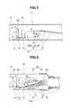
- FIG. 4is a view explaining a schematic configuration of a distal end portion of an endoscope with a bending portion as the first endoscope;
- FIG. 5is a view explaining a configuration of the endoscope with the bending portion
- FIG. 8is a view explaining a wiring state of wirings formed on both surfaces in a vicinity of a cut portion of a second board
- FIG. 9is a view explaining a board which is used as an image pickup unit for the first endoscope or an image pickup unit for the second endoscope;
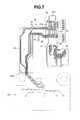
- FIG. 10is a perspective view explaining a unit portion set
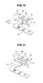
- FIG. 11is a perspective view explaining a unit portion set configuring the image pickup unit for the first endoscope.
- FIGS. 1 to 12One embodiment of the present invention will be described with reference to FIGS. 1 to 12 .
- an endoscope 1 with a bending portion(hereinafter, described as an endoscope) and a rigid endoscope (hereinafter, described as a rigid scope) 2 are respectively connected to a light source apparatus 3 and a video processor 4 .
- An endoscopic image picked up by an image pickup device which is included by the endoscope 1 and will be described later, or an endoscopic image picked up by an image pickup device which is included by the rigid scope 2 and will be described laterare displayed on a display apparatus 5 .
- the bending directions of the bending portion 12are set to be four directions that are upward, downward, leftward and rightward, but the bending directions may be, for example, two directions that are upward and downward.
- the first endoscopemay be a rigid scope with a bending portion including a bending portion in a vicinity of the distal end portion.
- the rigid scopeis configured by including a rigid tube portion instead of a flexible tube portion.
- the light source apparatus 3includes a light source connector connection portion 3 a , and includes an illumination lamp in the apparatus.
- the video processor 4includes a signal connector connection portion 4 a , and includes a control unit, a signal processing circuit, a storage unit and the like in the apparatus.
- the signal connector 18or a signal connector 25 of the rigid scope 2 is detachably connected.
- the display apparatus 5receives a video signal outputted from the video processor 4 , and displays an endoscopic image which is picked up by the endoscope 1 or the rigid scope 2 on a screen 5 a.
- the rigid scope 2is a second endoscope, and is configured by including a rigid insertion portion 21 , an operation section 22 which is connectively provided at a proximal end of the insertion portion 21 , and a universal cord 23 which is extended from the operation section 22 .
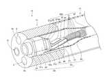
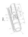
- An image pickup unit(reference numeral 30 in FIG. 2 and the like) which will be described later is placed in a distal end portion of the insertion portion 21 .
- Reference numeral 24designates a light source connector
- reference numeral 25designates a signal connector.
- Reference numeral 6designates a video cable, which connects the video processor 4 and the display apparatus 5 , and transmits the video signal outputted from the video processor 4 .
- the image pickup optical system 8is configured by including the lens frame 8 a , an image pickup frame 8 b , and a rigid pipe 8 c having a substantially circular section. Various optical lenses not illustrated are fixedly provided in the lens frame 8 a .
- the image pickup frame 8 bis fixed to the lens frame 8 a , and a cover lens 31 which configures the image pickup unit 30 is fixed in the image pickup frame 8 b .
- the rigid pipe 8 cis fixed to the image pickup frame 8 b , and the image pickup unit 30 is placed in the rigid pipe 8 c.
- the image pickup unit 30is configured by including the cover lens 31 , a cover glass 32 , an image pickup device 33 , a board 40 , and a flexible board 35 having flexibility to a thickness direction, as a signal transmission member.
- the image pickup device 33is configured to be in a substantially quadrangular shape, and has a substantially quadrangular image pickup surface 33 A.
- the cover lens 31is formed into a circle, and has an outside diameter slightly larger than that of the image pickup surface 33 A of the image pickup device 33 .
- the cover glass 32is formed into a substantially quadrangular shape, and has substantially the same width as the image pickup device 33 .
- the image pickup device 33 and various electronic components 34are mounted on the board 40 .
- a distal end portion of the flexible board 35is connected to a second terminal portion 52 formed at a board portion 42 for the second endoscope which configures the board 40 and will be described later.
- a proximal end portion of the flexible board 35is inserted through an inside of the rigid pipe 8 c and is extended into the operation section 22 .
- the cover lens 31 and the cover glass 32are bonded and fixed by a transparent adhesive, and the cover glass 32 is disposed on a light receiving surface of the image pickup device 33 . Further, a periphery of the electronic component 34 and peripheries of electric connection portions are sealed by a nonconductive resin. A nonconductive sealing resin is charged inside the rigid pipe 8 c.
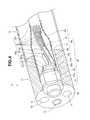
- the endoscope 1includes an illumination optical system 9 , an observation optical system 60 and a treatment instrument channel 70 in the insertion portion 10 .
- the treatment instrument channel 70is mainly configured by a channel pipe sleeve (not illustrated) configured by a metal pipe, and a channel tube (not illustrated) which is connected to the channel pipe sleeve and has flexibility.
- the channel tubeis inserted through the insertion portion 10 and is connected to a forceps insertion port 71 which is provided in the operation section 14 .
- a pair of illumination optical systems 9are provided with, for example, the observation optical system 60 therebetween.
- the illumination optical system 9is configured by an illuminating window 9 a which is fixedly provided at the distal end portion 11 , and a light guide fiber bundle not illustrated.
- the observation optical system 60is configured by including a lens frame 61 , an image pickup frame 62 , and an image pickup section sheathing frame 63 configured by stacking, for example, a thin metal sheet 64 and a heat-shrinkable tube 65 in layer.
- the image pickup section sheathing frame 63has its distal end portion fixed to a small-diameter portion 66 of the image pickup frame 62 .
- On the lens frame 61 and the image pickup frame 62at least peripheral surfaces which are disposed to be close to an outer peripheral side of the insertion portion 10 , and cutout surfaces 61 a and 62 a configured by planes opposed to the outer periphery are formed.
- At least peripheral surfaces disposed close to the outer peripheral side of the insertion portion 10 , and a pair of cutout surfaces 31 b configured by planes opposed to the outer peripheryare formed.
- a width of a pair of cutout surfaces of the cover lens 31 Ais formed to be slightly larger than a width of the image pickup device 33 .
- respective pairs of cutout surfaces 61 a , 62 a and 31 bare formed on the lens frame 61 , the image pickup frame 62 and the cover lens 31 A, and the respective cutout surfaces 61 a , 62 a and 31 b are disposed substantially parallel to both side surfaces of the image pickup device 33 .
- the observation optical system 60 and the treatment instrument channel 70can be disposed to be closer to each other when the observation optical system 60 and the treatment instrument channel 70 are arranged in an axial direction orthogonal to a longitudinal direction of the insertion portion 10 , and therefore, an configuration which can make an outside diameter of the distal end portion 11 smaller is provided.
- the board 40is configured by including the first endoscope board portion (hereinafter, abbreviated as a first board) 41 , a second endoscope board portion (hereinafter, abbreviated as a second board) 42 and an inspection board portion 43 .
- the first board 41has a substantially rectangular shape formed by a short side 41 a substantially parallel with the image pickup device 33 and a long side 41 b orthogonal to the short side 41 a .
- the second board 42has a substantially rectangular shape provided in parallel with the long side 41 b of the first board 41 to be separated from the long side 41 b by a predetermined distance.
- the first board 41 and the second board 42configure the integral board 40 by a connection portion 45 including a folding portion 44 for the second endoscope shown by the broken line along which a valley fold is made.
- connection portion 45has a cut portion 46 shown by the alternate long and short dashed line parallel with a side surface at the first board 41 side.
- the connection portion 45has the cut portion 46 in addition to the folding portion 44 for the second endoscope.
- the inspection board portion 43is provided at a proximal end side of the second board 42 .
- An inspection terminal portion 90 including a plurality of inspection terminals 91is formed in the inspection board portion 43 .
- the inspection board portion 43is cut along a cut line 43 C shown by the solid line after acceptance inspection is finished.
- the first board 41 and the second board 42respectively include terminal portions and wirings which will be described later on one surface side and the other surface side.
- a width dimension W 50 of the first connection portion 50is set to be smaller than a width dimension W 47 of the first mounting portion 47 and smaller than a width dimension W 48 of the second mounting portion 48 .
- the first connection portion 50 which is a folding portionis configured to be in a taper shape with a width dimension gradually changing to be smaller toward a proximal end side seen from a paper surface top direction of FIG. 6 when the second mounting portion 48 is brought into a folded state.
- the first mounting portion 47includes an image pickup device mounting surface 53 on which the image pickup device 33 is mounted, on one surface side, and includes a first terminal portion 51 to which the conductor wire portions 37 a of the aforesaid signal line 37 are respectively connected, on the other surface side.
- the first terminal portion 51includes, for example, terminals 81 to 91 .
- the terminals 81 to 91are formed by being divided into a first group in which the terminals 81 to 86 are arranged in the width direction, and a second group in which the terminals 87 to 91 are arranged in the width direction, toward the second mounting portion 48 from the image pickup device 33 side.
- the one surface side of the second mounting portion 48is the electronic component mounting surface on which the various electronic components 34 are mounted.
- a third mounting portion 54 on which the various electronic components 34 are mountedare provided beside the second mounting portion 48 .
- the second mounting portion 48 and the third mounting portion 54are integrally configured by a second connection portion 56 including a second folding portion 55 shown by the solid line along which a mounting fold is made.
- the configuration in which the third mounting portion 54 is provided beside the second mounting portion 48is shown, but the first mounting portion 47 , the second mounting portion 48 and the third mounting portion 54 may be disposed in series, and the second folding portion 55 and the first folding portion 49 may be disposed to be in a positional relation substantially parallel with each other. Further, when the number of the electronic components 34 is small, the third mounting portion 54 is not required.
- the second board 42includes a second terminal portion 52 to which the distal end portion of the aforesaid flexible board 35 is connected, on the one surface side.
- a width dimension W 42 of the second board 42is set to be larger than the width dimension W 47 of the first mounting portion 47 of the first board 41 . This is because when the second board 42 is folded along the folding portion 44 for the second endoscope of the aforesaid connection portion 45 and is disposed over the first mounting portion 47 , the second board 42 is disposed in a substantially central portion, which is wide, of the rigid pipe 8 c as shown in FIGS. 2 to 5 .
- the length dimension of the second board 42is set to be an optimal length dimension in consideration of an electrical connection work of the flexible board 35 .
- the second terminal portion 52is included in a region which is large in the width dimension and long in the length dimension as compared with the first mounting portion 47 including the first terminal portion 51 of the first board 41 .
- the terminals 81 to 91 which configure the second terminal portion 52are formed by being divided into a first group 52 A in which the terminals 81 to 85 are arranged in the width direction, a second group 52 B in which the terminals 86 , 87 , 90 and 91 are arranged in the width direction, and a third group 52 C in which the terminals 88 and 89 are arranged in the width direction, from the connection portion 45 side toward the cut line 43 C side.
- each of the terminals 81 to 91namely, at least one of the terminal width and the terminal length, or the distance between the terminals, in other words, at least the spaces of the respective terminals 81 to 85 of the first group 52 A in the width direction (arrow W direction in the drawing) of the second board 42 and the spaces between the respective terminals 86 , 87 , 90 and 91 of the second group 52 B, and the distance between the first group 52 A and the second group 52 B in the lengthwise direction (arrow L direction in the drawing) may be set to be large.
- the image pickup device 33 and the various electronic components 34are mounted on the board 40 , and the inspection board portion 43 is cut, as shown in FIG. 9 . Further, the board 40 on which the image pickup device 33 and the electronic component 34 are mounted is configured as a unit portion set 80 by being folded at the first folding portion 49 and the second folding portion 55 in predetermined states as shown in FIG. 10 .
- a workerforms a unit portion set 80 A for an endoscope with a bending portion by cutting the second board 42 from the cut portion 46 as shown in FIG. 11 .
- the wirings 57which are respectively formed on the one surface side and the other surface side of the second board 42 are set in the positional relation in which the wirings 57 are not overlaid on each other, and thereby, cut surfaces of the wirings 57 are prevented from being in electrical contact with each other when being cut.
- the signal cable 36 through which a plurality of signal lines 37 are insertedis connected to the first terminal portion 51 of the unit portion set 80 A for the endoscope with a bending portion. More specifically, the worker connects the conductor wire portions 37 a of the respective signal lines 37 , from which sheathing is removed, to the respective terminals 81 to 91 one by one. Subsequently, by completion of connection of the respective signal lines 37 to the respective terminals 81 to 91 , the image pickup unit 30 A as shown in the aforesaid FIGS. 4 and 5 is configured.
- a workerconnects the flexible board 35 to the second terminal portion 52 of the unit portion set 80 . More specifically, the worker performs positioning by facing the flexible board 35 and the second terminal portion 52 to each other as shown in FIG. 12 , and thereafter, collectively joins the flexible board 35 and the second terminal portion 52 by solder, bump, an anisotropic conductive resin or the like. Thereby, a terminal portion not illustrated of the flexible board 35 and the respective terminals 81 to 91 of the second terminal portion 52 can be electrically connected at one time.
- the workerAfter connecting the flexible board 35 to the second terminal portion 52 of the second board 42 , the worker folds the connection portion 45 of the second board 42 along the folding portion 44 for the second endoscope. By being folded in this manner, the second board 42 to which the flexible board 35 is connected is disposed by being stacked over the first mounting portion 47 with the electronic component 34 stacked thereon, and the image pickup unit 30 as shown in the aforesaid FIGS. 2 and 3 is configured.
- the terminals 81 to 91 of the first terminal portion 51 provided on the other surface side of the first mounting portion 47are insulated and sealed by pasting of a sealing resin or an insulating tape.
- the board 40 including the first board 41 provided with the first terminal portion 51 and the second board 42 provided with the second terminal portion 52is configured.
- the unit portion set 80 A for the endoscope with a bending portion in which the second board 42 is cut from the board 40is used, whereas when the image pickup unit 30 for the endoscope without a bending portion is configured, the unit portion set 80 is used without the second board 42 being cut.
- the board which is made common to the image pickup units for use in the endoscope having a bending portion and the endoscope without a bending portioncan be used.
- the image pickup unit 30is configured by using the unit portion set 80 A for the endoscope with a bending portion, and thereby, the rigid portion length of the flexible endoscope having a bending portion can be reduced.
- the flexible board 35is connected to the unit portion set 80 , whereby the less expensive flexible board 35 can be inserted through the inside of the insertion portion 21 of the rigid scope 2 instead of the expensive signal cable 36 such as a coaxial cable being inserted through the inside of the insertion portion 21 . Accordingly, the component of the rigid scope is made less expensive, and contribution to reduction in cost of the rigid scope can be made.
- the spaces between the respective terminals and terminal groups formed on the second board 42are set to be large as compared with the spaces between the respective terminals and the groups formed on the first board 41 , whereby the connecting work of the terminal portion of the flexible board 35 and the respective terminals 81 to 91 can be quickly and reliably performed by positioning being performed, and therefore, reduction in the assembly cost of the rigid scope can be achieved.
- the work of removing sheathing of a plurality of signal lines 37 which the signal cable 36 has and exposing the conductor wire portions 37 a by a predetermined amountis not required, whereby the working hour can be reduced, and further reduction in assembly cost can be achieved. These things can further contribute to cost reduction of the rigid scope.
Landscapes
- Health & Medical Sciences (AREA)
- Life Sciences & Earth Sciences (AREA)
- Surgery (AREA)
- Nuclear Medicine, Radiotherapy & Molecular Imaging (AREA)
- Biomedical Technology (AREA)
- Optics & Photonics (AREA)
- Pathology (AREA)
- Radiology & Medical Imaging (AREA)
- Biophysics (AREA)
- Engineering & Computer Science (AREA)
- Physics & Mathematics (AREA)
- Heart & Thoracic Surgery (AREA)
- Medical Informatics (AREA)
- Molecular Biology (AREA)
- Animal Behavior & Ethology (AREA)
- General Health & Medical Sciences (AREA)
- Public Health (AREA)
- Veterinary Medicine (AREA)
- Endoscopes (AREA)
Abstract
Description
Claims (7)
Applications Claiming Priority (3)
| Application Number | Priority Date | Filing Date | Title |
|---|---|---|---|
| JP2009-151300 | 2009-06-25 | ||
| JP2009151300 | 2009-06-25 | ||
| PCT/JP2010/060674WO2010150825A1 (en) | 2009-06-25 | 2010-06-23 | Image pickup unit |
Related Parent Applications (1)
| Application Number | Title | Priority Date | Filing Date |
|---|---|---|---|
| PCT/JP2010/060674ContinuationWO2010150825A1 (en) | 2009-06-25 | 2010-06-23 | Image pickup unit |
Publications (2)
| Publication Number | Publication Date |
|---|---|
| US20110295064A1 US20110295064A1 (en) | 2011-12-01 |
| US8821382B2true US8821382B2 (en) | 2014-09-02 |
Family
ID=43386594
Family Applications (1)
| Application Number | Title | Priority Date | Filing Date |
|---|---|---|---|
| US13/154,831Active2030-10-01US8821382B2 (en) | 2009-06-25 | 2011-06-07 | Image pickup unit |
Country Status (5)
| Country | Link |
|---|---|
| US (1) | US8821382B2 (en) |
| EP (1) | EP2446808A4 (en) |
| JP (1) | JP4916595B2 (en) |
| CN (1) | CN102802497B (en) |
| WO (1) | WO2010150825A1 (en) |
Cited By (5)
| Publication number | Priority date | Publication date | Assignee | Title |
|---|---|---|---|---|
| US20130258183A1 (en)* | 2012-03-30 | 2013-10-03 | Takatoshi Kamei | Support, imaging apparatus, and connection method for an imaging apparatus |
| US20140249368A1 (en)* | 2011-11-15 | 2014-09-04 | Fujikura Ltd. | Method of packaging imaging device chip, method of assembling endoscope, imaging module, and endoscope |
| US10485404B2 (en) | 2016-03-01 | 2019-11-26 | Karl Storz Endovision, Inc. | Compact image sensor module and method of assembly for image sensor modules |
| US10962092B2 (en) | 2017-09-08 | 2021-03-30 | Gates Corporation | Tensioner and method |
| US11333223B2 (en) | 2019-08-06 | 2022-05-17 | Gates Corporation | Orbital tensioner |
Families Citing this family (45)
| Publication number | Priority date | Publication date | Assignee | Title |
|---|---|---|---|---|
| WO2010146587A1 (en) | 2009-06-18 | 2010-12-23 | Peer Medical Ltd. | Multi-camera endoscope |
| US12137873B2 (en) | 2009-06-18 | 2024-11-12 | Endochoice, Inc. | Compact multi-viewing element endoscope system |
| US9492063B2 (en) | 2009-06-18 | 2016-11-15 | Endochoice Innovation Center Ltd. | Multi-viewing element endoscope |
| US9706903B2 (en) | 2009-06-18 | 2017-07-18 | Endochoice, Inc. | Multiple viewing elements endoscope system with modular imaging units |
| US9101287B2 (en) | 2011-03-07 | 2015-08-11 | Endochoice Innovation Center Ltd. | Multi camera endoscope assembly having multiple working channels |
| US9402533B2 (en) | 2011-03-07 | 2016-08-02 | Endochoice Innovation Center Ltd. | Endoscope circuit board assembly |
| US10165929B2 (en) | 2009-06-18 | 2019-01-01 | Endochoice, Inc. | Compact multi-viewing element endoscope system |
| US11547275B2 (en) | 2009-06-18 | 2023-01-10 | Endochoice, Inc. | Compact multi-viewing element endoscope system |
| US9642513B2 (en) | 2009-06-18 | 2017-05-09 | Endochoice Inc. | Compact multi-viewing element endoscope system |
| US11278190B2 (en) | 2009-06-18 | 2022-03-22 | Endochoice, Inc. | Multi-viewing element endoscope |
| US9713417B2 (en) | 2009-06-18 | 2017-07-25 | Endochoice, Inc. | Image capture assembly for use in a multi-viewing elements endoscope |
| US11864734B2 (en) | 2009-06-18 | 2024-01-09 | Endochoice, Inc. | Multi-camera endoscope |
| US8926502B2 (en) | 2011-03-07 | 2015-01-06 | Endochoice, Inc. | Multi camera endoscope having a side service channel |
| US9901244B2 (en) | 2009-06-18 | 2018-02-27 | Endochoice, Inc. | Circuit board assembly of a multiple viewing elements endoscope |
| US9872609B2 (en) | 2009-06-18 | 2018-01-23 | Endochoice Innovation Center Ltd. | Multi-camera endoscope |
| US9101268B2 (en) | 2009-06-18 | 2015-08-11 | Endochoice Innovation Center Ltd. | Multi-camera endoscope |
| US12220105B2 (en) | 2010-06-16 | 2025-02-11 | Endochoice, Inc. | Circuit board assembly of a multiple viewing elements endoscope |
| US9560953B2 (en) | 2010-09-20 | 2017-02-07 | Endochoice, Inc. | Operational interface in a multi-viewing element endoscope |
| EP2618718B1 (en) | 2010-09-20 | 2020-04-15 | EndoChoice Innovation Center Ltd. | Multi-camera endoscope having fluid channels |
| CN103403605A (en) | 2010-10-28 | 2013-11-20 | 恩多巧爱思创新中心有限公司 | Optical systems for multi-sensor endoscopes |
| US12204087B2 (en) | 2010-10-28 | 2025-01-21 | Endochoice, Inc. | Optical systems for multi-sensor endoscopes |
| US9320419B2 (en) | 2010-12-09 | 2016-04-26 | Endochoice Innovation Center Ltd. | Fluid channeling component of a multi-camera endoscope |
| US11889986B2 (en) | 2010-12-09 | 2024-02-06 | Endochoice, Inc. | Flexible electronic circuit board for a multi-camera endoscope |
| CN107361721B (en) | 2010-12-09 | 2019-06-18 | 恩多巧爱思创新中心有限公司 | Flexible electronic circuit boards for multi-camera endoscopes |
| JP5436470B2 (en)* | 2011-01-31 | 2014-03-05 | 富士フイルム株式会社 | Imaging device and electronic endoscope provided with the same |
| EP2672878B1 (en) | 2011-02-07 | 2017-11-22 | Endochoice Innovation Center Ltd. | Multi-element cover for a multi-camera endoscope |
| EP2604172B1 (en) | 2011-12-13 | 2015-08-12 | EndoChoice Innovation Center Ltd. | Rotatable connector for an endoscope |
| CA2798716A1 (en) | 2011-12-13 | 2013-06-13 | Peermedical Ltd. | Removable tip endoscope |
| JP5912058B2 (en)* | 2012-03-30 | 2016-04-27 | 株式会社フジクラ | Imaging module, imaging module with lens, endoscope, imaging module manufacturing method, flexible wiring board molding apparatus |
| CN104335660B (en)* | 2012-04-05 | 2018-06-19 | 瑞典爱立信有限公司 | The system access process of optimization |
| US9560954B2 (en) | 2012-07-24 | 2017-02-07 | Endochoice, Inc. | Connector for use with endoscope |
| US9986899B2 (en) | 2013-03-28 | 2018-06-05 | Endochoice, Inc. | Manifold for a multiple viewing elements endoscope |
| US9993142B2 (en) | 2013-03-28 | 2018-06-12 | Endochoice, Inc. | Fluid distribution device for a multiple viewing elements endoscope |
| US10499794B2 (en) | 2013-05-09 | 2019-12-10 | Endochoice, Inc. | Operational interface in a multi-viewing element endoscope |
| DE202013004379U1 (en)* | 2013-05-13 | 2013-05-31 | Schölly Fiberoptic GmbH | endoscope |
| JP6307227B2 (en)* | 2013-06-28 | 2018-04-04 | オリンパス株式会社 | Imaging unit and endoscope apparatus |
| JP6431698B2 (en)* | 2014-06-16 | 2018-11-28 | オリンパス株式会社 | Imaging unit, wiring board with cable, and method of manufacturing wiring board with cable |
| WO2016157597A1 (en)* | 2015-03-30 | 2016-10-06 | オリンパス株式会社 | Endoscope |
| JP2016214660A (en)* | 2015-05-22 | 2016-12-22 | ソニー・オリンパスメディカルソリューションズ株式会社 | Medical camera head and medical camera device |
| JP2017074207A (en)* | 2015-10-14 | 2017-04-20 | 富士フイルム株式会社 | Electronic endoscope |
| WO2017081718A1 (en)* | 2015-11-09 | 2017-05-18 | オリンパス株式会社 | Endoscope |
| JP6393018B1 (en)* | 2017-04-06 | 2018-09-19 | オリンパス株式会社 | Imaging unit and endoscope |
| WO2018186163A1 (en)* | 2017-04-06 | 2018-10-11 | オリンパス株式会社 | Imaging unit and endoscope |
| JP7390549B2 (en)* | 2019-09-30 | 2023-12-04 | パナソニックIpマネジメント株式会社 | Imaging units, equipment, and intercom systems |
| US11642016B2 (en)* | 2021-08-10 | 2023-05-09 | Altek Biotechnology Corporation | Image capturing module, endoscope and method of manufacturing image capturing module |
Citations (45)
| Publication number | Priority date | Publication date | Assignee | Title |
|---|---|---|---|---|
| US4831456A (en)* | 1986-12-08 | 1989-05-16 | Olympus Optical Co., Ltd. | Imaging apparatus using a solid-state imaging element having a substrate |
| US5010446A (en)* | 1989-10-30 | 1991-04-23 | Commonwealth Edison Company | Multi-edge extender board |
| US5021888A (en)* | 1987-12-18 | 1991-06-04 | Kabushiki Kaisha Toshiba | Miniaturized solid state imaging device |
| US5220198A (en)* | 1990-08-27 | 1993-06-15 | Olympus Optical Co., Ltd. | Solid state imaging apparatus in which a solid state imaging device chip and substrate are face-bonded with each other |
| JPH05211997A (en) | 1992-02-05 | 1993-08-24 | Asahi Optical Co Ltd | The tip of the electronic endoscope |
| US5411020A (en)* | 1990-11-27 | 1995-05-02 | Asahi Kogaku Kogyo Kabushiki Kaisha | Structure of the distal end portion of an endoscope |
| US5454366A (en)* | 1990-11-27 | 1995-10-03 | Asashi Kogaku Kogyo Kabushiki Kaisha | Endoscope distal end with folded circuit board |
| JPH0969983A (en) | 1995-08-30 | 1997-03-11 | Matsushita Electric Ind Co Ltd | Solid-state imaging device |
| JPH09192091A (en) | 1996-01-18 | 1997-07-29 | Fuji Photo Optical Co Ltd | Image sensor assembly for electronic endoscope |
| JPH09201331A (en) | 1996-01-26 | 1997-08-05 | Fuji Photo Optical Co Ltd | Image pick-up element assembly body for electronic endoscope |
| JPH09307087A (en) | 1996-05-17 | 1997-11-28 | Olympus Optical Co Ltd | Solid-state image pickup device |
| US5754313A (en)* | 1996-07-17 | 1998-05-19 | Welch Allyn, Inc. | Imager assembly |
| JPH10216084A (en) | 1997-02-10 | 1998-08-18 | Fuji Photo Optical Co Ltd | Imaging device for endoscope |
| JPH1176156A (en) | 1997-09-01 | 1999-03-23 | Olympus Optical Co Ltd | Imaging device |
| US6142930A (en)* | 1997-01-13 | 2000-11-07 | Asahi Kogaku Kogyo Kabushiki Kaisha | Electronic endoscope having compact construction |
| WO2000072744A2 (en)* | 1999-05-27 | 2000-12-07 | Karl Storz Gmbh & Co. Kg | Modular image recording system and method of assembling such a modular image recording system |
| JP2001095758A (en) | 1999-09-30 | 2001-04-10 | Fuji Photo Optical Co Ltd | Mounting device for image pickup element for endoscope |
| JP2001104247A (en) | 1999-10-12 | 2001-04-17 | Olympus Optical Co Ltd | Imaging device |
| JP2001120501A (en) | 1999-10-28 | 2001-05-08 | Olympus Optical Co Ltd | Solid image pickup device |
| US6313456B1 (en)* | 1999-01-25 | 2001-11-06 | Sony Corporation | Solid state imaging device having a box-shaped circuit board |
| US20040075620A1 (en)* | 2002-09-30 | 2004-04-22 | Satoshi Tanaka | Folding portable terminal |
| US20040171914A1 (en)* | 2001-06-18 | 2004-09-02 | Dov Avni | In vivo sensing device with a circuit board having rigid sections and flexible sections |
| US20050007130A1 (en)* | 1996-05-23 | 2005-01-13 | Genesis Technology Incorporated | Contact probe and probe device |
| US20050143658A1 (en)* | 2003-12-26 | 2005-06-30 | Olympus Corporation | Ultrasonic endoscope and ultrasonic signal cable connector device |
| US20050143659A1 (en)* | 2003-12-26 | 2005-06-30 | Olympus Corporation | Ultrasonic endoscope and ultrasonic signal cable connector device |
| US20060001820A1 (en)* | 2004-07-05 | 2006-01-05 | Yin-Tsung Cheng | Liquid crystal module |
| US20060087022A1 (en)* | 2004-10-21 | 2006-04-27 | Chipmos Technologies (Bermuda) Ltd. | Image sensor assembly and method for fabricating the same |
| US20060157271A1 (en)* | 2005-01-17 | 2006-07-20 | J. S. T. Mfg. Co., Ltd. | Double-sided flexible printed circuits |
| US20060241422A1 (en)* | 2005-03-31 | 2006-10-26 | Given Imaging Ltd. | Antenna for in-vivo imaging system |
| US20070081309A1 (en)* | 2005-08-31 | 2007-04-12 | Sony Corporation | Circuit substrate |
| US20070096234A1 (en)* | 2005-11-02 | 2007-05-03 | Pentax Corporation | Image pickup device mounting structure |
| US20070229656A1 (en)* | 2006-03-27 | 2007-10-04 | Semion Khait | Battery contacts for an in-vivo imaging device |
| US20080131112A1 (en)* | 2006-11-30 | 2008-06-05 | Hitachi Maxell, Ltd. | Camera module and imaging apparatus |
| WO2008087771A1 (en) | 2007-01-16 | 2008-07-24 | Olympus Medical Systems Corp. | Imaging device, and endoscope |
| JP2008227733A (en) | 2007-03-09 | 2008-09-25 | Olympus Medical Systems Corp | Imaging device |
| US20090082624A1 (en)* | 2005-03-18 | 2009-03-26 | Hidehiro Joko | Endoscope, endoscope system, and switching circuit member for endoscope |
| US20090126976A1 (en)* | 2007-11-21 | 2009-05-21 | Fujifilm Corporation | Flexible wiring board, method of producing the same and imaging device |
| US20090227147A1 (en)* | 2008-03-05 | 2009-09-10 | Canon Kabushiki Kaisha | Electronic apparatus |
| US20090259101A1 (en)* | 2008-04-15 | 2009-10-15 | Olympus Medical Systems Corp. | Image pickup apparatus and endoscope apparatus incorporating the same |
| US20090283300A1 (en)* | 2008-05-16 | 2009-11-19 | Apple Inc. | Flex Circuit with Single Sided Routing and Double Sided Attach |
| US20090292169A1 (en)* | 2008-05-21 | 2009-11-26 | Olympus Medical Systems Corp. | Electronic endoscope apparatus |
| US20100016039A1 (en)* | 2006-07-25 | 2010-01-21 | Mayumi Tokuyama | Flexible printed board, electronic apparatus mounted with this, and folding method for flexible printed board |
| US7775971B2 (en)* | 2004-01-19 | 2010-08-17 | Olympus Corporation | Capsule apparatus with rigid and flexible wiring board sections |
| US7868429B2 (en)* | 2007-12-12 | 2011-01-11 | Altek Corporation | Micro-sensor and manufacturing method thereof |
| US8289720B2 (en)* | 2009-02-04 | 2012-10-16 | Canon Kabushiki Kaisha | Electronic apparatus |
Family Cites Families (3)
| Publication number | Priority date | Publication date | Assignee | Title |
|---|---|---|---|---|
| JP4377821B2 (en)* | 2005-01-17 | 2009-12-02 | オリンパス株式会社 | Endoscope electrical connector, endoscope, and assembly method of electrical connector |
| JP5308652B2 (en)* | 2007-11-19 | 2013-10-09 | オリンパスメディカルシステムズ株式会社 | Imaging unit |
| TWI370334B (en) | 2007-12-20 | 2012-08-11 | Ind Tech Res Inst | Holographic gratings and method of fabricating the same |
- 2010
- 2010-06-23JPJP2011519922Apatent/JP4916595B2/enactiveActive
- 2010-06-23EPEP10792143Apatent/EP2446808A4/ennot_activeWithdrawn
- 2010-06-23CNCN201080027895.8Apatent/CN102802497B/enactiveActive
- 2010-06-23WOPCT/JP2010/060674patent/WO2010150825A1/enactiveApplication Filing
- 2011
- 2011-06-07USUS13/154,831patent/US8821382B2/enactiveActive
Patent Citations (55)
| Publication number | Priority date | Publication date | Assignee | Title |
|---|---|---|---|---|
| US4831456A (en)* | 1986-12-08 | 1989-05-16 | Olympus Optical Co., Ltd. | Imaging apparatus using a solid-state imaging element having a substrate |
| US5021888A (en)* | 1987-12-18 | 1991-06-04 | Kabushiki Kaisha Toshiba | Miniaturized solid state imaging device |
| US5010446A (en)* | 1989-10-30 | 1991-04-23 | Commonwealth Edison Company | Multi-edge extender board |
| US5220198A (en)* | 1990-08-27 | 1993-06-15 | Olympus Optical Co., Ltd. | Solid state imaging apparatus in which a solid state imaging device chip and substrate are face-bonded with each other |
| US5411020A (en)* | 1990-11-27 | 1995-05-02 | Asahi Kogaku Kogyo Kabushiki Kaisha | Structure of the distal end portion of an endoscope |
| US5454366A (en)* | 1990-11-27 | 1995-10-03 | Asashi Kogaku Kogyo Kabushiki Kaisha | Endoscope distal end with folded circuit board |
| JPH05211997A (en) | 1992-02-05 | 1993-08-24 | Asahi Optical Co Ltd | The tip of the electronic endoscope |
| US6417885B1 (en)* | 1995-08-30 | 2002-07-09 | Matsushita Electric Industrial Co., Ltd. | Solid-state image pickup device with a separable circuit board |
| JPH0969983A (en) | 1995-08-30 | 1997-03-11 | Matsushita Electric Ind Co Ltd | Solid-state imaging device |
| JPH09192091A (en) | 1996-01-18 | 1997-07-29 | Fuji Photo Optical Co Ltd | Image sensor assembly for electronic endoscope |
| JPH09201331A (en) | 1996-01-26 | 1997-08-05 | Fuji Photo Optical Co Ltd | Image pick-up element assembly body for electronic endoscope |
| JPH09307087A (en) | 1996-05-17 | 1997-11-28 | Olympus Optical Co Ltd | Solid-state image pickup device |
| US20050007130A1 (en)* | 1996-05-23 | 2005-01-13 | Genesis Technology Incorporated | Contact probe and probe device |
| US5754313A (en)* | 1996-07-17 | 1998-05-19 | Welch Allyn, Inc. | Imager assembly |
| US6142930A (en)* | 1997-01-13 | 2000-11-07 | Asahi Kogaku Kogyo Kabushiki Kaisha | Electronic endoscope having compact construction |
| JPH10216084A (en) | 1997-02-10 | 1998-08-18 | Fuji Photo Optical Co Ltd | Imaging device for endoscope |
| JPH1176156A (en) | 1997-09-01 | 1999-03-23 | Olympus Optical Co Ltd | Imaging device |
| US6313456B1 (en)* | 1999-01-25 | 2001-11-06 | Sony Corporation | Solid state imaging device having a box-shaped circuit board |
| US20020080233A1 (en)* | 1999-05-27 | 2002-06-27 | Irion Klaus M. | Image pick-up module and method for assembling such an image pick-up module |
| US8189062B2 (en)* | 1999-05-27 | 2012-05-29 | Karl Storz Gmbh & Co, Kg | Image pick-up module and method for assembling such an image pick-up module |
| US20090027491A1 (en)* | 1999-05-27 | 2009-01-29 | Irion Klaus M | Image Pick-Up Module And Method For Assembling Such An Image Pick-Up Module |
| US7773122B2 (en)* | 1999-05-27 | 2010-08-10 | Karl Storz Gmbh & Co. Kg | Image pick-up module and method for assembling such an image pick-up module |
| WO2000072744A2 (en)* | 1999-05-27 | 2000-12-07 | Karl Storz Gmbh & Co. Kg | Modular image recording system and method of assembling such a modular image recording system |
| JP2001095758A (en) | 1999-09-30 | 2001-04-10 | Fuji Photo Optical Co Ltd | Mounting device for image pickup element for endoscope |
| JP2001104247A (en) | 1999-10-12 | 2001-04-17 | Olympus Optical Co Ltd | Imaging device |
| JP2001120501A (en) | 1999-10-28 | 2001-05-08 | Olympus Optical Co Ltd | Solid image pickup device |
| US20040171914A1 (en)* | 2001-06-18 | 2004-09-02 | Dov Avni | In vivo sensing device with a circuit board having rigid sections and flexible sections |
| US7998065B2 (en)* | 2001-06-18 | 2011-08-16 | Given Imaging Ltd. | In vivo sensing device with a circuit board having rigid sections and flexible sections |
| US20040075620A1 (en)* | 2002-09-30 | 2004-04-22 | Satoshi Tanaka | Folding portable terminal |
| US20050143659A1 (en)* | 2003-12-26 | 2005-06-30 | Olympus Corporation | Ultrasonic endoscope and ultrasonic signal cable connector device |
| US20050143658A1 (en)* | 2003-12-26 | 2005-06-30 | Olympus Corporation | Ultrasonic endoscope and ultrasonic signal cable connector device |
| US7775971B2 (en)* | 2004-01-19 | 2010-08-17 | Olympus Corporation | Capsule apparatus with rigid and flexible wiring board sections |
| US20060001820A1 (en)* | 2004-07-05 | 2006-01-05 | Yin-Tsung Cheng | Liquid crystal module |
| US20060087022A1 (en)* | 2004-10-21 | 2006-04-27 | Chipmos Technologies (Bermuda) Ltd. | Image sensor assembly and method for fabricating the same |
| US20060157271A1 (en)* | 2005-01-17 | 2006-07-20 | J. S. T. Mfg. Co., Ltd. | Double-sided flexible printed circuits |
| US8137265B2 (en)* | 2005-03-18 | 2012-03-20 | Olympus Medical Systems Corp. | Endoscope, endoscope system, and switching circuit member for endoscope |
| US20090082624A1 (en)* | 2005-03-18 | 2009-03-26 | Hidehiro Joko | Endoscope, endoscope system, and switching circuit member for endoscope |
| US20060241422A1 (en)* | 2005-03-31 | 2006-10-26 | Given Imaging Ltd. | Antenna for in-vivo imaging system |
| US7801586B2 (en)* | 2005-03-31 | 2010-09-21 | Given Imaging Ltd. | Antenna for in-vivo imaging system |
| US20070081309A1 (en)* | 2005-08-31 | 2007-04-12 | Sony Corporation | Circuit substrate |
| US20070096234A1 (en)* | 2005-11-02 | 2007-05-03 | Pentax Corporation | Image pickup device mounting structure |
| US20070229656A1 (en)* | 2006-03-27 | 2007-10-04 | Semion Khait | Battery contacts for an in-vivo imaging device |
| US20100016039A1 (en)* | 2006-07-25 | 2010-01-21 | Mayumi Tokuyama | Flexible printed board, electronic apparatus mounted with this, and folding method for flexible printed board |
| US20080131112A1 (en)* | 2006-11-30 | 2008-06-05 | Hitachi Maxell, Ltd. | Camera module and imaging apparatus |
| JP2008177701A (en) | 2007-01-16 | 2008-07-31 | Olympus Medical Systems Corp | Imaging device |
| US20090268019A1 (en) | 2007-01-16 | 2009-10-29 | Olympus Medical Systems Corp. | Image pickup apparatus and endoscope |
| WO2008087771A1 (en) | 2007-01-16 | 2008-07-24 | Olympus Medical Systems Corp. | Imaging device, and endoscope |
| JP2008227733A (en) | 2007-03-09 | 2008-09-25 | Olympus Medical Systems Corp | Imaging device |
| US20090126976A1 (en)* | 2007-11-21 | 2009-05-21 | Fujifilm Corporation | Flexible wiring board, method of producing the same and imaging device |
| US7868429B2 (en)* | 2007-12-12 | 2011-01-11 | Altek Corporation | Micro-sensor and manufacturing method thereof |
| US20090227147A1 (en)* | 2008-03-05 | 2009-09-10 | Canon Kabushiki Kaisha | Electronic apparatus |
| US20090259101A1 (en)* | 2008-04-15 | 2009-10-15 | Olympus Medical Systems Corp. | Image pickup apparatus and endoscope apparatus incorporating the same |
| US20090283300A1 (en)* | 2008-05-16 | 2009-11-19 | Apple Inc. | Flex Circuit with Single Sided Routing and Double Sided Attach |
| US20090292169A1 (en)* | 2008-05-21 | 2009-11-26 | Olympus Medical Systems Corp. | Electronic endoscope apparatus |
| US8289720B2 (en)* | 2009-02-04 | 2012-10-16 | Canon Kabushiki Kaisha | Electronic apparatus |
Non-Patent Citations (2)
| Title |
|---|
| Extended Supplementary European Search Report dated Dec. 5, 2012 from related application EP 10792143.9-1265. |
| International Search Report dated Aug. 10, 2010. |
Cited By (7)
| Publication number | Priority date | Publication date | Assignee | Title |
|---|---|---|---|---|
| US20140249368A1 (en)* | 2011-11-15 | 2014-09-04 | Fujikura Ltd. | Method of packaging imaging device chip, method of assembling endoscope, imaging module, and endoscope |
| US10510918B2 (en)* | 2011-11-15 | 2019-12-17 | Fujikura Ltd. | Endoscope imaging module |
| US20130258183A1 (en)* | 2012-03-30 | 2013-10-03 | Takatoshi Kamei | Support, imaging apparatus, and connection method for an imaging apparatus |
| US8988600B2 (en)* | 2012-03-30 | 2015-03-24 | Kabushiki Kaisha Toshiba | Support, imaging apparatus, and connection method for an imaging apparatus |
| US10485404B2 (en) | 2016-03-01 | 2019-11-26 | Karl Storz Endovision, Inc. | Compact image sensor module and method of assembly for image sensor modules |
| US10962092B2 (en) | 2017-09-08 | 2021-03-30 | Gates Corporation | Tensioner and method |
| US11333223B2 (en) | 2019-08-06 | 2022-05-17 | Gates Corporation | Orbital tensioner |
Also Published As
| Publication number | Publication date |
|---|---|
| US20110295064A1 (en) | 2011-12-01 |
| EP2446808A1 (en) | 2012-05-02 |
| JPWO2010150825A1 (en) | 2012-12-10 |
| WO2010150825A1 (en) | 2010-12-29 |
| JP4916595B2 (en) | 2012-04-11 |
| EP2446808A4 (en) | 2013-01-02 |
| CN102802497B (en) | 2015-03-25 |
| CN102802497A (en) | 2012-11-28 |
Similar Documents
| Publication | Publication Date | Title |
|---|---|---|
| US8821382B2 (en) | Image pickup unit | |
| JP5308716B2 (en) | Electronic endoscope device | |
| EP1988812B1 (en) | Endoscope with an imaging catheter assembly and method of configuring an endoscope | |
| US8289381B2 (en) | Endoscope with an imaging catheter assembly and method of configuring an endoscope | |
| US20160367122A1 (en) | Solid-state image pickup apparatus and electronic endoscope including solid-state image pickup apparatus | |
| CN103648404B (en) | Ultrasonic endoscope | |
| US20070293720A1 (en) | Endoscope assembly and method of viewing an area inside a cavity | |
| US20090231419A1 (en) | Endoscope Assembly and Method of Performing a Medical Procedure | |
| US20200154982A1 (en) | Endoscope system and endoscope converter | |
| JP2011212161A (en) | Solid-state image pickup device and endoscopic device | |
| EP2211683A2 (en) | Endoscope assembly comprising retrograde viewing imaging device and instrument channel | |
| WO2007087421A2 (en) | Endoscope | |
| EP1986541A2 (en) | Endoscope | |
| US20190296537A1 (en) | Cable structure, mount module, and endoscope | |
| EP3244603A1 (en) | Imaging unit, imaging module and endoscopic system | |
| US20140039258A1 (en) | Endoscope insertion shape observation probe | |
| US10624528B2 (en) | Connector | |
| JP2000232957A (en) | Endoscopic device | |
| JP2008253451A (en) | Distal end structure of endoscope | |
| US11857166B2 (en) | Imaging unit and endoscope | |
| US20230052510A1 (en) | Multilayer board, probe unit, and ultrasound endoscope | |
| WO2019097588A1 (en) | Cable connection structure, imaging device, and endoscope | |
| JP4197796B2 (en) | Electronic endoscope | |
| JP2022124502A (en) | ultrasound endoscope | |
| JP3762600B2 (en) | Electronic endoscope |
Legal Events
| Date | Code | Title | Description |
|---|---|---|---|
| AS | Assignment | Owner name:OLYMPUS MEDICAL SYSTEMS CORP., JAPAN Free format text:ASSIGNMENT OF ASSIGNORS INTEREST;ASSIGNOR:KAGAWA, HIROAKI;REEL/FRAME:026757/0283 Effective date:20110808 | |
| STCF | Information on status: patent grant | Free format text:PATENTED CASE | |
| FEPP | Fee payment procedure | Free format text:PAYOR NUMBER ASSIGNED (ORIGINAL EVENT CODE: ASPN); ENTITY STATUS OF PATENT OWNER: LARGE ENTITY | |
| AS | Assignment | Owner name:OLYMPUS CORPORATION, JAPAN Free format text:ASSIGNMENT OF ASSIGNORS INTEREST;ASSIGNOR:OLYMPUS MEDICAL SYSTEMS CORP.;REEL/FRAME:036276/0543 Effective date:20150401 | |
| AS | Assignment | Owner name:OLYMPUS CORPORATION, JAPAN Free format text:CHANGE OF ADDRESS;ASSIGNOR:OLYMPUS CORPORATION;REEL/FRAME:039344/0502 Effective date:20160401 | |
| MAFP | Maintenance fee payment | Free format text:PAYMENT OF MAINTENANCE FEE, 4TH YEAR, LARGE ENTITY (ORIGINAL EVENT CODE: M1551) Year of fee payment:4 | |
| MAFP | Maintenance fee payment | Free format text:PAYMENT OF MAINTENANCE FEE, 8TH YEAR, LARGE ENTITY (ORIGINAL EVENT CODE: M1552); ENTITY STATUS OF PATENT OWNER: LARGE ENTITY Year of fee payment:8 |