US8821365B2 - Rotation drive device and centrifugal pump apparatus using the same - Google Patents
Rotation drive device and centrifugal pump apparatus using the sameDownload PDFInfo
- Publication number
- US8821365B2 US8821365B2US13/387,637US201013387637AUS8821365B2US 8821365 B2US8821365 B2US 8821365B2US 201013387637 AUS201013387637 AUS 201013387637AUS 8821365 B2US8821365 B2US 8821365B2
- Authority
- US
- United States
- Prior art keywords
- permanent magnets
- impeller
- diaphragm
- magnetic
- rotor
- Prior art date
- Legal status (The legal status is an assumption and is not a legal conclusion. Google has not performed a legal analysis and makes no representation as to the accuracy of the status listed.)
- Expired - Fee Related
Links
Images


Classifications
- H—ELECTRICITY
- H02—GENERATION; CONVERSION OR DISTRIBUTION OF ELECTRIC POWER
- H02K—DYNAMO-ELECTRIC MACHINES
- H02K7/00—Arrangements for handling mechanical energy structurally associated with dynamo-electric machines, e.g. structural association with mechanical driving motors or auxiliary dynamo-electric machines
- H02K7/14—Structural association with mechanical loads, e.g. with hand-held machine tools or fans
- A—HUMAN NECESSITIES
- A61—MEDICAL OR VETERINARY SCIENCE; HYGIENE
- A61M—DEVICES FOR INTRODUCING MEDIA INTO, OR ONTO, THE BODY; DEVICES FOR TRANSDUCING BODY MEDIA OR FOR TAKING MEDIA FROM THE BODY; DEVICES FOR PRODUCING OR ENDING SLEEP OR STUPOR
- A61M60/00—Blood pumps; Devices for mechanical circulatory actuation; Balloon pumps for circulatory assistance
- A61M60/10—Location thereof with respect to the patient's body
- A—HUMAN NECESSITIES
- A61—MEDICAL OR VETERINARY SCIENCE; HYGIENE
- A61M—DEVICES FOR INTRODUCING MEDIA INTO, OR ONTO, THE BODY; DEVICES FOR TRANSDUCING BODY MEDIA OR FOR TAKING MEDIA FROM THE BODY; DEVICES FOR PRODUCING OR ENDING SLEEP OR STUPOR
- A61M60/00—Blood pumps; Devices for mechanical circulatory actuation; Balloon pumps for circulatory assistance
- A61M60/20—Type thereof
- A61M60/205—Non-positive displacement blood pumps
- A61M60/216—Non-positive displacement blood pumps including a rotating member acting on the blood, e.g. impeller
- A61M60/226—Non-positive displacement blood pumps including a rotating member acting on the blood, e.g. impeller the blood flow through the rotating member having mainly radial components
- A61M60/232—Centrifugal pumps
- A—HUMAN NECESSITIES
- A61—MEDICAL OR VETERINARY SCIENCE; HYGIENE
- A61M—DEVICES FOR INTRODUCING MEDIA INTO, OR ONTO, THE BODY; DEVICES FOR TRANSDUCING BODY MEDIA OR FOR TAKING MEDIA FROM THE BODY; DEVICES FOR PRODUCING OR ENDING SLEEP OR STUPOR
- A61M60/00—Blood pumps; Devices for mechanical circulatory actuation; Balloon pumps for circulatory assistance
- A61M60/40—Details relating to driving
- A61M60/403—Details relating to driving for non-positive displacement blood pumps
- A61M60/422—Details relating to driving for non-positive displacement blood pumps the force acting on the blood contacting member being electromagnetic, e.g. using canned motor pumps
- A—HUMAN NECESSITIES
- A61—MEDICAL OR VETERINARY SCIENCE; HYGIENE
- A61M—DEVICES FOR INTRODUCING MEDIA INTO, OR ONTO, THE BODY; DEVICES FOR TRANSDUCING BODY MEDIA OR FOR TAKING MEDIA FROM THE BODY; DEVICES FOR PRODUCING OR ENDING SLEEP OR STUPOR
- A61M60/00—Blood pumps; Devices for mechanical circulatory actuation; Balloon pumps for circulatory assistance
- A61M60/80—Constructional details other than related to driving
- A61M60/802—Constructional details other than related to driving of non-positive displacement blood pumps
- A61M60/818—Bearings
- A61M60/824—Hydrodynamic or fluid film bearings
- F—MECHANICAL ENGINEERING; LIGHTING; HEATING; WEAPONS; BLASTING
- F04—POSITIVE - DISPLACEMENT MACHINES FOR LIQUIDS; PUMPS FOR LIQUIDS OR ELASTIC FLUIDS
- F04D—NON-POSITIVE-DISPLACEMENT PUMPS
- F04D13/00—Pumping installations or systems
- F04D13/02—Units comprising pumps and their driving means
- F04D13/06—Units comprising pumps and their driving means the pump being electrically driven
- F04D13/0606—Canned motor pumps
- F04D13/0633—Details of the bearings
- F—MECHANICAL ENGINEERING; LIGHTING; HEATING; WEAPONS; BLASTING
- F04—POSITIVE - DISPLACEMENT MACHINES FOR LIQUIDS; PUMPS FOR LIQUIDS OR ELASTIC FLUIDS
- F04D—NON-POSITIVE-DISPLACEMENT PUMPS
- F04D13/00—Pumping installations or systems
- F04D13/02—Units comprising pumps and their driving means
- F04D13/06—Units comprising pumps and their driving means the pump being electrically driven
- F04D13/0606—Canned motor pumps
- F04D13/064—Details of the magnetic circuit
- F—MECHANICAL ENGINEERING; LIGHTING; HEATING; WEAPONS; BLASTING
- F04—POSITIVE - DISPLACEMENT MACHINES FOR LIQUIDS; PUMPS FOR LIQUIDS OR ELASTIC FLUIDS
- F04D—NON-POSITIVE-DISPLACEMENT PUMPS
- F04D13/00—Pumping installations or systems
- F04D13/02—Units comprising pumps and their driving means
- F04D13/06—Units comprising pumps and their driving means the pump being electrically driven
- F04D13/0666—Units comprising pumps and their driving means the pump being electrically driven the motor being of the plane gap type
- F—MECHANICAL ENGINEERING; LIGHTING; HEATING; WEAPONS; BLASTING
- F04—POSITIVE - DISPLACEMENT MACHINES FOR LIQUIDS; PUMPS FOR LIQUIDS OR ELASTIC FLUIDS
- F04D—NON-POSITIVE-DISPLACEMENT PUMPS
- F04D29/00—Details, component parts, or accessories
- F04D29/04—Shafts or bearings, or assemblies thereof
- F04D29/046—Bearings
- F04D29/048—Bearings magnetic; electromagnetic
- H—ELECTRICITY
- H02—GENERATION; CONVERSION OR DISTRIBUTION OF ELECTRIC POWER
- H02K—DYNAMO-ELECTRIC MACHINES
- H02K1/00—Details of the magnetic circuit
- H02K1/06—Details of the magnetic circuit characterised by the shape, form or construction
- H02K1/22—Rotating parts of the magnetic circuit
- H02K1/27—Rotor cores with permanent magnets
- H02K1/2793—Rotors axially facing stators
- H02K1/2795—Rotors axially facing stators the rotor consisting of two or more circumferentially positioned magnets
- H—ELECTRICITY
- H02—GENERATION; CONVERSION OR DISTRIBUTION OF ELECTRIC POWER
- H02K—DYNAMO-ELECTRIC MACHINES
- H02K21/00—Synchronous motors having permanent magnets; Synchronous generators having permanent magnets
- H02K21/12—Synchronous motors having permanent magnets; Synchronous generators having permanent magnets with stationary armatures and rotating magnets
- H02K21/24—Synchronous motors having permanent magnets; Synchronous generators having permanent magnets with stationary armatures and rotating magnets with magnets axially facing the armatures, e.g. hub-type cycle dynamos
- H—ELECTRICITY
- H02—GENERATION; CONVERSION OR DISTRIBUTION OF ELECTRIC POWER
- H02K—DYNAMO-ELECTRIC MACHINES
- H02K5/00—Casings; Enclosures; Supports
- H02K5/04—Casings or enclosures characterised by the shape, form or construction thereof
- H02K5/12—Casings or enclosures characterised by the shape, form or construction thereof specially adapted for operating in liquid or gas
- H02K5/128—Casings or enclosures characterised by the shape, form or construction thereof specially adapted for operating in liquid or gas using air-gap sleeves or air-gap discs
- H02K5/1282—Casings or enclosures characterised by the shape, form or construction thereof specially adapted for operating in liquid or gas using air-gap sleeves or air-gap discs the partition wall in the air-gap being non cylindrical
- A—HUMAN NECESSITIES
- A61—MEDICAL OR VETERINARY SCIENCE; HYGIENE
- A61M—DEVICES FOR INTRODUCING MEDIA INTO, OR ONTO, THE BODY; DEVICES FOR TRANSDUCING BODY MEDIA OR FOR TAKING MEDIA FROM THE BODY; DEVICES FOR PRODUCING OR ENDING SLEEP OR STUPOR
- A61M60/00—Blood pumps; Devices for mechanical circulatory actuation; Balloon pumps for circulatory assistance
- A61M60/10—Location thereof with respect to the patient's body
- A61M60/122—Implantable pumps or pumping devices, i.e. the blood being pumped inside the patient's body
- A61M60/126—Implantable pumps or pumping devices, i.e. the blood being pumped inside the patient's body implantable via, into, inside, in line, branching on, or around a blood vessel
- A61M60/148—Implantable pumps or pumping devices, i.e. the blood being pumped inside the patient's body implantable via, into, inside, in line, branching on, or around a blood vessel in line with a blood vessel using resection or like techniques, e.g. permanent endovascular heart assist devices
- A—HUMAN NECESSITIES
- A61—MEDICAL OR VETERINARY SCIENCE; HYGIENE
- A61M—DEVICES FOR INTRODUCING MEDIA INTO, OR ONTO, THE BODY; DEVICES FOR TRANSDUCING BODY MEDIA OR FOR TAKING MEDIA FROM THE BODY; DEVICES FOR PRODUCING OR ENDING SLEEP OR STUPOR
- A61M60/00—Blood pumps; Devices for mechanical circulatory actuation; Balloon pumps for circulatory assistance
- A61M60/80—Constructional details other than related to driving
- A61M60/802—Constructional details other than related to driving of non-positive displacement blood pumps
- A61M60/818—Bearings
- A61M60/82—Magnetic bearings
- H—ELECTRICITY
- H02—GENERATION; CONVERSION OR DISTRIBUTION OF ELECTRIC POWER
- H02K—DYNAMO-ELECTRIC MACHINES
- H02K7/00—Arrangements for handling mechanical energy structurally associated with dynamo-electric machines, e.g. structural association with mechanical driving motors or auxiliary dynamo-electric machines
- H02K7/08—Structural association with bearings
- H02K7/09—Structural association with bearings with magnetic bearings
Definitions
- the present inventionrelates to a rotation drive device and a centrifugal pump apparatus using the same, and more particularly to a rotation drive device for transmitting a driving force with a diaphragm interposed therebetween and a centrifugal pump apparatus using the same.
- canned motorshaving a structure including a motor drive chamber and a rotor chamber separated from each other by a diaphragm have been widely used.
- Such motoris used for a pump for transporting pure water in a semiconductor manufacturing line used in an environment that avoids dust, and a pump for transporting a biological solution, for example.
- Pumps for transporting a biological solutioninclude a centrifugal blood pump apparatus using a direct drive motor for directly transmitting torque to an impeller in a blood chamber.
- This centrifugal blood pump apparatuscan eliminate physical contact between the blood chamber and the outside to prevent invasion of bacteria and the like into blood, and is thus used as an artificial heart. Since an artificial heart is driven by electric power from a battery, enhancement of motor efficiency is critical.
- a centrifugal blood pump in Japanese Patent Laying-Open No. 2004-209240includes a housing having first to third chambers partitioned from one another by first and second diaphragms, an impeller rotatably provided in the second chamber (blood chamber), a magnetic material provided in one surface of the impeller, an electromagnet provided in the first chamber to face the one surface of the impeller, a permanent magnet provided in the other surface of the impeller, a rotor and a motor provided in the third chamber, and a permanent magnet provided in the rotor to face the other surface of the impeller.
- Grooves for hydrodynamic bearingare formed in a surface of the second diaphragm facing the other surface of the impeller.
- the impellermoves away from an inner surface of the second chamber, and rotates without contacting.
- a centrifugal blood pump in Japanese Patent Laying-Open No. 2006-167173includes a housing having first to third chambers partitioned from one another by first and second diaphragms, an impeller rotatably provided in the second chamber (blood chamber), a magnetic material provided in one surface of the impeller, a first permanent magnet provided in the first chamber to face the one surface of the impeller, a second permanent magnet provided in the other surface of the impeller, a rotor and a motor provided in the third chamber, and a third permanent magnet provided in the rotor to face the other surface of the impeller.
- First grooves for hydrodynamic bearingare formed in a surface of the first diaphragm facing the one surface of the impeller, and second grooves for hydrodynamic bearing are formed in a surface of the second diaphragm facing the other surface of the impeller. Due to an attractive force acting on the one surface of the impeller from the first permanent magnet, an attractive force acting on the other surface of the impeller from the third permanent magnet in the rotor, and a hydrodynamic bearing effect of the first and second grooves for hydrodynamic bearing, the impeller moves away from an inner surface of the second chamber, and rotates without contacting.
- a turbo-type pump in FIGS. 8 and 9 of Japanese Patent Laying-Open No. 4-91396includes a housing, an impeller rotatably provided in the housing, a first permanent magnet provided in one surface of the impeller, a rotor provided outside of the housing, a second permanent magnet provided in the rotor to face the one surface of the impeller, a third permanent magnet provided in the other surface of the impeller, and a magnetic material provided in the housing to face the other surface of the impeller.
- First grooves for hydrodynamic bearingare formed in the one surface of the impeller, and second grooves for hydrodynamic bearing are formed in the other surface of the impeller.
- the impellermoves away from an inner surface of the housing, and rotates without contacting.
- a clean pump in Japanese Utility Model Laying-Open No. 6-53790includes a casing, an impeller rotatably provided in the casing, a first permanent magnet provided in one surface of the impeller, a rotor provided outside of the casing, a second permanent magnet provided in the rotor to face the one surface of the impeller, a magnetic material provided in the other surface of the impeller, and an electromagnet provided outside of the housing to face the other surface of the impeller.
- Grooves for hydrodynamic bearingare formed in the one surface of the impeller.
- the electromagnetis operated when a rotation speed of the impeller is lower than a predetermined rotation speed, and power supply to the electromagnet is stopped when the rotation speed of the impeller becomes higher than the predetermined rotation speed. Due to an attractive force acting on the one surface of the impeller from the second permanent magnet in the rotor, and a hydrodynamic bearing effect of the grooves for hydrodynamic bearing, the impeller moves away from an inner surface of the housing, and rotates without contacting.
- the pumps in PTLs 1 to 4 described aboveshare the feature of axially supporting the impeller by the grooves for hydrodynamic bearing formed in a portion where the impeller and the housing face each other, and radially supporting the impeller by the attractive force between the permanent magnet provided in the impeller and the permanent magnet provided outside of the housing.
- Supporting rigidity of grooves for hydrodynamic bearingis proportionate to a rotation speed of an impeller.
- axial rigidity for the impellerneeds to be enhanced by increasing a normal rotation speed range of the pump.
- the impelleris radially supported by utilizing the attractive force of the permanent magnets, and so the supporting rigidity is low, resulting in inability to rotate the impeller at high speed.
- One way to increase the radial rigidityis to increase the attractive force between the permanent magnet in the impeller and the permanent magnet or a stator provided outside of the housing.
- a negative axial rigidity value of the impellerincreases (namely, as the impeller moves axially, the attractive force increases correspondingly).
- supporting function on the impeller by hydrodynamic pressure and the attractive force acting between the impeller and the housingincrease, resulting in difficulty in smoothly driving the impeller to rotate.
- the negative axial rigidity value of the impelleris higher than positive rigidity resulting from hydrodynamic pressure, stable rotation cannot be obtained.
- radial supportis provided by a passive magnetic bearing with a permanent magnet, radial rigidity is determined by a negative axial rigidity value. It is thus difficult to improve the radial rigidity under conditions for realizing stable rotation, and the mass of the impeller must not be increased in order for the impeller to rotate without contacting the housing.
- PTL 2proposes a method of providing an electromagnet for biasing the impeller toward a predetermined direction, and a magnetic force adjustment coil for varying a magnetic force of the permanent magnets, and operating them when activating the impeller to rotate, to smoothly activate the impeller.
- this approachrequires new dedicated members such as the electromagnet and the coil, which increases a pump size, and the increased number of components results in lower reliability.
- a main object of the present inventionis to provide a small rotation drive device capable of generating large torque and achieving high energy efficiency, and a centrifugal pump apparatus using the same.
- a rotation drive deviceincludes a housing having first and second chambers partitioned from each other by a diaphragm, a rotor rotatably provided in the first chamber along the diaphragm, and drive means provided in the second chamber for driving the rotor to rotate with the diaphragm interposed therebetween.
- This rotation drive deviceincludes a plurality of first permanent magnets provided in the rotor and aligned with a gap therebetween in a rotation direction of the rotor. Each of the first permanent magnets is magnetized in a direction orthogonal to the rotation direction of the rotor. Every two adjacent ones of the first permanent magnets have magnetic polarities different from each other.
- the drive meansincludes a plurality of first magnetic materials arranged to face the plurality of first permanent magnets, and a plurality of coils wound around the plurality of first magnetic materials, respectively, for generating a rotating magnetic field. Accordingly, by providing the gaps between the first permanent magnets while maintaining the weight of the first permanent magnets at a constant value, magnetic flux density between the first permanent magnets can be increased to increase a magnetic coupling force between the rotor and the drive means. As a result, large torque can be obtained while maintaining small device dimensions.
- the rotation drive devicefurther includes a second magnetic material provided in the rotor, arranged on a side of the plurality of first permanent magnets opposite to a side closer to the diaphragm, and magnetically coupled to the plurality of first permanent magnets.
- the magnetic coupling force between the rotor and the drive meanscan be increased to obtain larger torque.
- copper loss that occurs in the coilscan be reduced, thereby enhancing energy efficiency in driving the rotor to rotate.
- the rotation drive devicefurther includes a plurality of second permanent magnets provided in the rotor and magnetically coupled to the plurality of first permanent magnets, in which each of the second permanent magnets is provided correspondingly to a gap between every two adjacent ones of the first permanent magnets, and is magnetized in the rotation direction of the rotor.
- the magnetic coupling force between the rotor and the drive meanscan be increased to obtain larger torque.
- copper loss that occurs in the coilscan be reduced, thereby enhancing energy efficiency in driving the rotor to rotate.
- each of the second permanent magnetsis arranged to cover a corresponding gap from a side opposite to the diaphragm, and each magnetic polarity of each of the second permanent magnets is identical to an adjacent magnetic polarity of the second permanent magnet, and is different from a corresponding magnetic polarity of the first permanent magnet.
- the rotation drive devicefurther includes a plurality of second magnetic materials provided in the rotor and inserted in the plurality of gaps between the plurality of second permanent magnets, respectively.
- the magnetic coupling force between the rotor and the drive meanscan be increased to obtain larger torque.
- copper loss that occurs in the coilscan be reduced, thereby enhancing energy efficiency in driving the rotor to rotate.
- each of the second permanent magnetsis inserted in a corresponding gap.
- Each of the second permanent magnetshas a first magnetic polarity oriented to one of the two adjacent first permanent magnets having the first magnetic polarity oriented to the diaphragm.
- Each of the second permanent magnetshas a second magnetic polarity oriented to the other of the two adjacent first permanent magnets having the second magnetic polarity oriented to the diaphragm.
- the magnetic coupling force between the rotor and the drive means for generating torquecan be increased while reducing an attractive force between the rotor and the drive means, to obtain larger torque.
- copper loss that occurs in the coilscan be reduced, thereby enhancing energy efficiency in driving the rotor to rotate.
- the dimensions of the magnetscan be minimized to reduce the dimensions of the device.
- a ratio of a surface area of each of the second permanent magnets facing the diaphragm to a surface area of each of the first permanent magnets facing the diaphragmis set to be 1 ⁇ 2 or more and 2 or less.
- the magnetic coupling force between the rotor and the drive means for generating torquecan be maximized while reducing an attractive force between the rotor and the drive means.
- the diaphragmis formed in a cylindrical shape, and the rotor and the drive means are arranged with a gap therebetween in a radial direction of the rotor.
- the rotation drive deviceis a radial gap type motor.
- the diaphragmis formed in a plane shape, and the rotor and the drive means are arranged with a gap therebetween in a direction in which a rotation central axis of the rotor extends.
- the rotation drive deviceis an axial gap type motor.
- a centrifugal pump apparatusincludes the rotation drive device described above.
- the rotoris an impeller for delivering liquid by a centrifugal force during rotation.
- centrifugal pump apparatusincludes a housing having first and second chambers partitioned from each other by a diaphragm, an impeller rotatably provided in the first chamber along the diaphragm for delivering liquid by a centrifugal force during rotation, and drive means provided in the second chamber for driving the impeller to rotate with the diaphragm interposed therebetween.
- This centrifugal pump apparatusincludes a first magnetic material provided in one surface of the impeller, a second magnetic material provided in an inner wall of the first chamber facing the one surface of the impeller, for attracting the first magnetic material, and a plurality of first permanent magnets provided in the other surface of the impeller and aligned with a gap therebetween in a rotation direction of the impeller.
- the drive meansincludes a plurality of third magnetic materials arranged to face the plurality of first permanent magnets, and a plurality of coils provided correspondingly to the plurality of third magnetic materials and wound around corresponding ones of the third magnetic materials, respectively, for generating a rotating magnetic field.
- a first attractive force between the first and second magnetic materials and a second attractive force between the plurality of first permanent magnets and the plurality of third magnetic materialsare balanced with each other substantially in a center of a movable range of the impeller in the first chamber.
- First grooves for hydrodynamic bearingare formed in the one surface of the impeller or in the inner wall of the first chamber facing the one surface, and second grooves for hydrodynamic bearing are formed in the other surface of the impeller or in the diaphragm facing the other surface.
- the liquidis blood
- the centrifugal pump apparatusis used for circulating the blood.
- the impelleris smoothly activated to rotate to secure a distance between the impeller and the housing, thereby preventing occurrence of hemolysis.
- large torque for driving a rotor or an impeller to rotatecan be generated while maintaining small device dimensions.
- energy efficiency in driving the rotor or the impeller to rotatecan be enhanced.
- hemolysiscan be avoided when circulating blood.
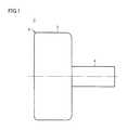
- FIG. 1is a front view showing the appearance of a pump unit of a centrifugal blood pump apparatus according to a first embodiment of the present invention.
- FIG. 2is a side view of the pump unit shown in FIG. 1 .
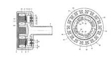
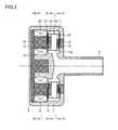
- FIG. 3is a cross-sectional view along the line in III-III FIG. 2 .
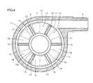
- FIG. 4is a cross-sectional view along the line IV-IV in FIG. 3 .
- FIG. 5is a cross-sectional view showing a state where an impeller has been removed from the cross-sectional view along the line IV-IV in FIG. 3 .
- FIG. 6is a cross-sectional view showing the state where the impeller has been removed from a cross-sectional view along the line VI-VI in FIG. 3 .
- FIG. 7is a cross-sectional view along the line VII-VII in FIG. 3 .
- FIG. 8is a time chart illustrating voltages applied to a plurality of coils shown in FIG. 7 .
- FIG. 9explains a levitation position of the impeller shown in FIG. 3 .
- FIG. 10explains a levitation position of the impeller shown in FIG. 3 .
- FIG. 11is a block diagram showing a structure of a controller for controlling the pump unit shown in FIGS. 1 to 7 .
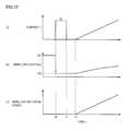
- FIG. 12is a time chart illustrating operation of the controller shown in FIG. 11 .
- FIG. 13is a cross-sectional view showing a comparative example of the first embodiment.
- FIG. 14explains the effect of the first embodiment.
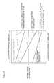
- FIG. 15illustrates relation between an area ratio of a gap portion to a permanent magnet shown in FIG. 14 and rotational torque.
- FIG. 16shows a modification of the first embodiment.
- FIG. 17shows another modification of the first embodiment.
- FIG. 18shows yet another modification of the first embodiment.
- FIG. 19shows yet another modification of the first embodiment.
- FIG. 20shows an optimal range of an area ratio of a permanent magnet 31 to a permanent magnet 17 shown in FIG. 19 .
- FIG. 21is a block diagram showing yet another modification of the first embodiment.
- FIG. 22is a time chart illustrating yet another modification of the first embodiment.
- FIG. 23is a cross-sectional view showing yet another modification of the first embodiment.
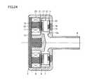
- FIG. 24is a cross-sectional view showing yet another modification of the first embodiment.
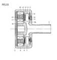
- FIG. 25is a cross-sectional view showing yet another modification of the first embodiment.
- FIG. 26is a cross-sectional view showing yet another modification of the first embodiment.
- FIG. 27is a cross-sectional view showing yet another modification of the first embodiment.
- FIG. 28is a cross-sectional view showing yet another modification of the first embodiment.
- FIG. 29shows a permanent magnet shown in FIG. 28 .
- FIG. 30is a cross-sectional view showing a structure of a pump unit of a centrifugal blood pump apparatus according to a second embodiment of the present invention.
- FIG. 31is a cross-sectional view along the line XXXI-XXXI in FIG. 30 .
- FIG. 32is a time chart illustrating an output signal from a magnetic sensor shown in FIG. 31 .
- FIG. 33is a block diagram showing a structure of a controller for controlling the pump unit shown in FIGS. 30 to 32 .
- FIG. 34is a block diagram showing a modification of the second embodiment.
- FIG. 35is a block diagram showing another modification of the second embodiment.
- FIG. 36is a block diagram showing yet another modification of the second embodiment.
- FIG. 37is a cross-sectional view showing yet another modification of the second embodiment.
- FIG. 38is a cross-sectional view showing yet another modification of the second embodiment.
- FIG. 39shows a structure of an axial gap type motor according to a third embodiment of the present invention.
- FIG. 40shows a comparative example of the third embodiment.
- FIG. 41shows a modification of the third embodiment.
- FIG. 42shows another modification of the third embodiment.
- FIG. 43shows yet another modification of the third embodiment.
- FIG. 44shows yet another modification of the third embodiment.
- FIG. 45shows a structure of a radial gap type motor according to a fourth embodiment of the present invention.
- FIG. 46shows a comparative example of the fourth embodiment.
- FIG. 47shows a modification of the fourth embodiment.
- FIG. 48shows another modification of the fourth embodiment.
- FIG. 49shows yet another modification of the fourth embodiment.
- FIG. 50shows yet another modification of the fourth embodiment.
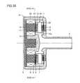
- a pump unit 1 of this centrifugal blood pump apparatusincludes a housing 2 made of a nonmagnetic material.
- Housing 2includes a cylindrical body portion 3 , a cylindrical blood inlet port 4 provided to stand at a center of one end surface of body portion 3 , and a cylindrical blood outlet port 5 provided on an outer circumferential surface of body portion 3 .
- Blood outlet port 5extends in a tangential direction of the outer circumferential surface of body portion 3 .
- a blood chamber 7 and a motor chamber 8 partitioned from each other by a diaphragm 6are provided in housing 2 .
- a disc-shaped impeller 10having a through hole 10 a in a center thereof is rotatably provided in blood chamber 7 .
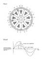
- Impeller 10includes two shrouds 11 , 12 in a doughnut plate shape, and a plurality of (e.g., six) vanes 13 formed between two shrouds 11 and 12 .
- Shroud 11is arranged closer to blood inlet port 4
- shroud 12is arranged closer to diaphragm 6 .
- Shrouds 11 , 12 and vanes 13are made of a nonmagnetic material.
- a plurality of (six in this case) blood passages 14 partitioned from one another by the plurality of vanes 13are formed between two shrouds 11 and 12 .
- blood passage 14is in communication with through hole 10 a in the center of impeller 10 , and extends with through hole 10 a of impeller 10 as a starting point to an outer circumference such that blood passage 14 gradually increases in width.
- vane 13is formed between two adjacent blood passages 14 .
- the plurality of vanes 13are provided at equiangular intervals, and have the same shape.
- the plurality of blood passages 14are provided at equiangular intervals, and have the same shape.
- a permanent magnet 15is embedded in shroud 11
- a permanent magnet 16 for attracting permanent magnet 15is embedded in an inner wall of blood chamber 7 facing shroud 11 .
- Permanent magnets 15 and 16are provided to attract (in other words, bias) impeller 10 to the side opposite to motor chamber 8 , namely, toward blood inlet port 4 .
- a permanent magnetmay be provided in one of shroud 11 and the inner wall of blood chamber 7 , and a magnetic material may be provided in the other.
- shroud 11itself may be formed of permanent magnet 15 or a magnetic material. Either a soft magnetic material or a hard magnetic material may be used as the magnetic material.
- Permanent magnet 16may be a single magnet, or a plurality of magnets. If it is a single magnet, permanent magnet 16 is formed in a ring shape. If it is a plurality of magnets, permanent magnets 16 are arranged at equiangular intervals along a single circle. As with permanent magnet 16 , permanent magnet 15 may also be a single magnet, or a plurality of magnets.
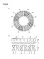
- a plurality of (e.g., eight) permanent magnets 17are embedded in shroud 12 .
- the plurality of permanent magnets 17are arranged with a gap therebetween at equiangular intervals along a single circle such that adjacent magnetic polarities are different from each other.
- permanent magnet 17 having the N-pole oriented to motor chamber 8 and permanent magnet 17 having the S-pole oriented to motor chamber 8are alternately arranged with a gap therebetween at equiangular intervals along a single circle.
- a plurality of (e.g., nine) magnetic materials 18are provided in motor chamber 8 .
- the plurality of magnetic materials 18are arranged at equiangular intervals along a single circle to face the plurality of permanent magnets 17 in impeller 10 .
- a base end of each of the plurality of magnetic materials 18is joined to one disc-shaped yoke 19 .
- a coil 20is wound around each magnetic material 18 .
- Each of the plurality of magnetic materials 18is formed in a shape of a triangular prism of the same dimensions.
- space for winding coil 20is equally secured around the plurality of magnetic materials 18 , and opposite surfaces of every two adjacent magnetic materials 18 are provided substantially parallel to each other.
- large space for coils 20can be secured, to increase turns of coils 20 .
- large torque for driving impeller 10 to rotatecan be generated.
- copper loss that occurs in coils 20can be reduced, thereby enhancing energy efficiency in driving impeller 10 to rotate.
- An outline surface surrounding the plurality of magnetic materials 18may correspond to an outline surface surrounding the plurality of permanent magnets 17 (a circle surrounding the peripheries of the plurality of magnetic materials 17 in FIG. 4 ), or the outline surface surrounding the plurality of magnetic materials 18 may be larger than the outline surface surrounding the plurality of permanent magnets 17 . Further, it is preferable that magnetic material 18 be designed not to be magnetically saturated at maximum rating of pump 1 (a condition where torque for driving impeller 10 to rotate becomes maximum).
- Each magnetic material 18may be formed in a cylindrical shape. In this case, a circumferential length of coils 20 can be minimized to reduce copper loss that occurs in coils 20 , thereby enhancing energy efficiency in driving impeller 10 to rotate.
- Voltagesare applied to nine coils 20 in a power distribution system shifted by 120 degrees, for example. That is, nine coils 20 are divided into groups each including three coils. Voltages VU, VV and VW as shown in FIG. 8 are applied to first to third coils 20 of each group, respectively.
- a positive voltageis applied during a period of 0 to 120 degrees
- 0 Vis applied during a period of 120 to 180 degrees
- a negative voltageis applied during a period of 180 to 300 degrees
- 0 Vis applied during a period of 300 to 360 degrees.
- a tip surface of magnetic material 18 having first coil 20 wound therearoundbecomes the N-pole during the period of 0 to 120 degrees, and becomes the S-pole during the period of 180 to 300 degrees.
- Voltage VVis delayed in phase from voltage VU by 120 degrees
- voltage VWis delayed in phase from voltage VV by 120 degrees.
- a rotating magnetic fieldcan be generated by applying voltages VU, VV and VW to first to third coils 20 , respectively, and impeller 10 can be rotated by an attractive force and a repulsion force between the plurality of magnetic materials 18 and the plurality of permanent magnets 17 in impeller 10 .
- a surface of impeller 10 and a surface of an inner wall of housing 2are not damaged (no projections and depressions in the surfaces) during the relative slide, and moreover, impeller 10 is readily levitated from housing 2 without contacting even when hydrodynamic pressure is small during low-speed rotation. Accordingly, occurrence of hemolysis/thrombus due to the relative slide between impeller 10 and housing 2 , or occurrence of thrombus due to small damage (projections and depressions) to the surfaces which occurs during the relative slide can be avoided.
- a plurality of grooves for hydrodynamic bearing 21are formed in a surface of diaphragm 6 facing shroud 12 of impeller 10
- a plurality of grooves for hydrodynamic bearing 22are formed in the inner wall of blood chamber 7 facing shroud 11 .
- the plurality of grooves for hydrodynamic bearing 21are formed with a size corresponding to shroud 12 of impeller 10 .
- Each of grooves for hydrodynamic bearing 21has one end on an edge (circumference) of a circular portion slightly distant from a center of diaphragm 6 , and extends spirally (in other words, in a curved manner) to a portion near an outer edge of diaphragm 6 such that grooves for hydrodynamic bearing 21 gradually increase in width.
- the plurality of grooves for hydrodynamic bearing 21have substantially the same shape, and are arranged at substantially the same intervals.
- Grooves for hydrodynamic bearing 21are concave portions, and preferably have a depth of about 0.005 to 0.4 mm. It is preferable that about 6 to 36 grooves for hydrodynamic bearing 21 be provided.
- ten grooves for hydrodynamic bearing 21are equiangularly arranged with respect to a central axis of impeller 10 . Since grooves for hydrodynamic bearing 21 have a so-called inward spiral groove shape, clockwise rotation of impeller 10 causes increase in liquid pressure from an outer diameter portion toward an inner diameter portion of grooves for hydrodynamic bearing 21 . As a result, a repulsion force is generated between impeller 10 and diaphragm 6 , and this acts as hydrodynamic pressure.
- grooves for hydrodynamic bearing 21may be provided in a surface of shroud 12 of impeller 10 .
- impeller 10moves away from diaphragm 6 , and rotates without contacting. Accordingly, a blood flow path is secured between impeller 10 and diaphragm 6 , thus preventing occurrence of blood accumulation therebetween and the resultant thrombus. Further, in a normal state, grooves for hydrodynamic bearing 21 exercise a stirring effect between impeller 10 and diaphragm 6 , thus preventing occurrence of partial blood accumulation therebetween.
- a corner portion of each of grooves for hydrodynamic bearing 21be rounded to have R of at least equal to higher than 0.05 mm. As a result, occurrence of hemolysis can be further reduced.
- the plurality of grooves for hydrodynamic bearing 22are formed with a size corresponding to shroud 11 of impeller 10 .
- Each of grooves for hydrodynamic bearing 22has one end on an edge (circumference) of a circular portion slightly distant from a center of the inner wall of blood chamber 7 , and extends spirally (in other words, in a curved manner) to a portion near an outer edge of the inner wall of blood chamber 7 such that grooves for hydrodynamic bearing 22 gradually increase in width.
- the plurality of grooves for hydrodynamic bearing 22have substantially the same shape, and are arranged at substantially the same intervals.
- Grooves for hydrodynamic bearing 22are concave portions, and preferably have a depth of about 0.005 to 0.4 mm. It is preferable that about 6 to 36 grooves for hydrodynamic bearing 22 be provided. In FIG. 6 , ten grooves for hydrodynamic bearing 22 are equiangularly arranged with respect to the central axis of impeller 10 .
- grooves for hydrodynamic bearing 22may be provided in a surface of shroud 11 of impeller 10 . It is preferable that a corner portion of each of grooves for hydrodynamic bearing 22 be rounded to have R of at least equal to or higher than 0.05 mm. As a result, occurrence of hemolysis can be further reduced.
- impeller 10moves away from the inner wall of blood chamber 7 , and rotates without contacting.
- impeller 10can be prevented from being in close contact with the inner wall of blood chamber 7 .
- the hydrodynamic pressure generated by grooves for hydrodynamic bearing 21may be different from the hydrodynamic pressure generated by grooves for hydrodynamic bearing 22 .
- impeller 10rotate in a state where a gap between shroud 12 of impeller 10 and diaphragm 6 is substantially equal to a gap between shroud 11 of impeller 10 and the inner wall of blood chamber 7 . If one of the gaps becomes narrower due to serious disturbance such as a hydrodynamic force acting on impeller 10 , it is preferable that grooves for hydrodynamic bearing 21 and 22 have different shapes, so that the hydrodynamic pressure by the grooves for hydrodynamic bearing on the narrower side becomes higher than the hydrodynamic pressure by the other grooves for hydrodynamic bearing to make the gaps substantially equal to each other.
- grooves for hydrodynamic bearing 21 and 22have the inward spiral groove shape in FIGS. 5 and 6
- grooves for hydrodynamic bearing 21 and 22 having another shapemay be used. Nevertheless, for blood circulation, it is preferable to employ grooves for hydrodynamic bearing 21 and 22 having the inward spiral groove shape that allows a smooth flow of blood.
- FIG. 9illustrates forces acting on impeller 10 when magnitude of a resultant force of an attractive force F 1 between permanent magnets 15 and 16 and an attractive force F 2 between permanent magnet 17 and magnetic material 18 is adjusted to be zero in a position P 1 other than a central position of the movable range of impeller 10 in blood chamber 7 .
- the rotation speed of impeller 10is kept at a rated value.
- a levitation position of impeller 10 when attractive force F 1 between permanent magnets 15 and 16 is set to be smaller than attractive force F 2 between permanent magnet 17 and magnetic material 18 and their resultant force becomes zerois closer to diaphragm 6 relative to the center of the movable range of the impeller.
- Grooves for hydrodynamic bearing 21 and 22have the same shape.
- a horizontal axis of FIG. 9represents a position of impeller 10 (the left side in the figure being closer to the diaphragm 6 ), and a vertical axis represents acting forces on impeller 10 .
- An acting force on impeller 10 toward diaphragm 6is expressed as a negative acting force.
- attractive force F 1 between permanent magnets 15 and 16attractive force F 2 between permanent magnet 17 and magnetic material 18
- a hydrodynamic pressure F 3 by grooves for hydrodynamic bearing 21a hydrodynamic pressure F 4 by grooves for hydrodynamic bearing 22
- a “net force F 5 acting on impeller”which is their resultant force are illustrated.
- FIG. 10illustrates forces acting on impeller 10 when the magnitude of the resultant force of attractive force F 1 between permanent magnets 15 and 16 and attractive force F 2 between permanent magnet 17 and magnetic material 18 is adjusted to be zero in a central position P 0 of the movable range of impeller 10 in blood chamber 7 .
- the rotation speed of impeller 10is kept at the rated value in this case as well.
- attractive force F 1 between permanent magnets 15 and 16 and attractive force F 2 between permanent magnet 17 and magnetic material 18are set to be substantially equal to each other.
- grooves for hydrodynamic bearing 21 and 22have the same shape. In this case, supporting rigidity for the levitation position of impeller 10 is high as compared to the example shown in FIG. 9 . Further, since net force F 5 acting on impeller 10 is zero in the center of the movable range, impeller 10 is levitated in the central position when a disturbance force is not acting on impeller 10 .
- a levitation position of impeller 10is determined by a balance among attractive force F 1 between permanent magnets 15 and 16 , attractive force F 2 between permanent magnet 17 and magnetic material 18 , and hydrodynamic pressures F 3 , F 4 generated by grooves for hydrodynamic bearing 21 and 22 during rotation of impeller 10 .
- F 1 and F 2substantially equal to each other, and by forming grooves for hydrodynamic bearing 21 and 22 in the same shape, impeller 10 can be levitated substantially in a central portion of blood chamber 7 during rotation of impeller 10 .
- impeller 10has a shape in which the vanes are formed between the two discs, as shown in FIGS. 3 and 4 , two surfaces facing the inner wall of housing 2 can be formed in the same shape and of the same dimensions. Therefore, it is possible to provide grooves for hydrodynamic bearing 21 and 22 having substantially the same hydrodynamic pressure generating function on both sides of impeller 10 .
- impeller 10is levitated in the central position of blood chamber 7 , and thus held in a position farthest from the inner wall of housing 2 .
- the levitation position of impeller 10is changed due to application of a disturbance force to levitated impeller 10 , the possibility that impeller 10 is brought into contact with the inner wall of housing 2 is reduced, thus reducing the possibility of occurrence of thrombus and hemolysis resulting from such contact.
- grooves for hydrodynamic bearing 21 and 22may have different shapes and different hydrodynamic pressure generating functions.
- the function of grooves for hydrodynamic bearing in the disturbance directionmay be made greater than the function of the other grooves for hydrodynamic bearing, thereby levitating and rotating impeller 10 in the central position of housing 2 .
- the possibility of contact between impeller 10 and housing 2can be reduced, thereby attaining stable levitation function of impeller 10 .
- an absolute value of a negative axial supporting rigidity value of impeller 10 which is constituted of attractive force F 1 between permanent magnets 15 and 16 and attractive force F 2 between permanent magnet 17 and magnetic material 18is expressed as Ka
- an absolute value of a positive radial rigidity valueis expressed as Kr
- an absolute value of a positive rigidity value obtained by two grooves for hydrodynamic bearing 21 and 22 in a normal rotation speed range where impeller 10 rotatesis expressed as Kg, it is preferable that a relation of Kg>Ka+Kr be satisfied.
- absolute value Kg of the positive rigidity value obtained by two grooves for hydrodynamic bearing 21 and 22 in the rotation speed range where impeller 10 normally rotatesis set to a value higher than 30000 N/m.
- the axial supporting rigidity for impeller 10is a value obtained by subtracting negative rigidity due to the attractive force between the magnetic materials and the like from rigidity resulting from the hydrodynamic pressures generated by grooves for hydrodynamic bearing 21 and 22 .
- the axial supporting rigidity for impeller 10can be made higher than the radial supporting rigidity. With such setting, movement of impeller 10 can be suppressed more in the axial direction than in the radial direction when a disturbance force acts on impeller 10 , thereby avoiding mechanical contact between impeller 10 and housing 2 in a portion where grooves for hydrodynamic bearing 21 are formed.
- grooves for hydrodynamic bearing 21 and 22are provided as concave portions in the planes as shown in FIGS. 5 and 6 , mechanical contact between housing 2 and impeller 10 in these sites during rotation of impeller 10 may result in damage to one or both of a surface of impeller 10 and a surface of the inner wall of housing 2 (projections and depressions in the surfaces), and blood passage through this portion may cause occurrence of thrombus and hemolysis.
- itis effective to make the axial rigidity higher than the radial rigidity.
- Whirloccurs in unbalanced impeller 10 during rotation, and this whirl is greatest when a natural frequency determined by the mass of impeller 10 and the supporting rigidity value of impeller 10 matches the rotation speed of impeller 10 .
- a maximum rotation speed of impeller 10is equal to or lower than the radial natural frequency. Accordingly, in order to prevent mechanical contact between impeller 10 and housing 2 , when a radial rigidity value of impeller 10 which is constituted of attractive force F 1 between permanent magnets 15 and 16 and attractive force F 2 between permanent magnet 17 and magnetic material 18 is expressed as Kr (N/m), the mass of impeller 10 is expressed as m (kg), and the rotation speed of the impeller is expressed as ⁇ (rad/s), it is preferable that a relation of ⁇ (Kr/m) 0.5 be satisfied.
- the maximum rotation speed of impeller 10is set to be equal to or lower than 258 rad/s (2465 rpm).
- the maximum rotation speed of impeller 10is set to 366 rad/s (3500 rpm)
- the radial rigidityis set to be equal to or higher than 4018 N/m.
- the maximum rotation speed of impeller 10is set to be equal to or lower than 80% of this ⁇ . Specifically, when the mass of impeller 10 is 0.03 kg and the radial rigidity value is 2000 N/m, the maximum rotation speed is set to be equal to or lower than 206.4 rad/s (1971 rpm). Conversely, when it is desired to set the maximum rotation speed of impeller 10 to 366 rad/s (3500 rpm), the radial rigidity value is set to be equal to or higher than 6279 N/m. By setting the maximum rotation speed of impeller 10 in this manner, contact between rotating impeller 10 and housing 2 can be suppressed.
- impeller 10When the rigidity due to the hydrodynamic pressures by grooves for hydrodynamic bearing 21 and 22 becomes higher than the negative axial rigidity value of impeller 10 which is constituted of attractive force F 1 between permanent magnets 15 and 16 and attractive force F 2 between permanent magnet 17 and magnetic material 18 , impeller 10 and housing 2 are not in contact with each other. It is thus preferable to minimize this negative rigidity value. In order to keep this negative rigidity value low, it is preferable that the opposite surfaces of permanent magnets 15 and 16 have different sizes.
- impeller 10is in contact with diaphragm 6 before activating impeller 10 to rotate.
- impeller 10when impeller 10 is not rotating, impeller 10 is not supported without contacting by grooves for hydrodynamic bearing 21 and 22 , but is in contact with housing 2 with a high surface pressure due to attractive force F 1 between permanent magnets 15 and 16 and attractive force F 2 between permanent magnet 17 and magnetic material 18 . Further, when impeller 10 is rotated by magnetic interaction between coil 20 and magnetic material 18 in motor chamber 8 and permanent magnet 7 in impeller 10 as in pump unit 1 , starting torque is small as compared to an example where an impeller is driven to rotate by magnetic coupling between permanent magnets as shown in FIG. 3 of PTL 2. It is thus difficult to smoothly activate impeller 10 to rotate.
- this centrifugal blood pump apparatusis provided with means for moving impeller 10 toward diaphragm 6 before activating impeller 10 to rotate. Specifically, a current is fed through the plurality of coils 20 such that attractive force F 2 between permanent magnet 17 and magnetic material 18 becomes higher, to move impeller 10 toward diaphragm 6 .
- FIG. 11is a block diagram showing a structure of a controller 25 for controlling pump unit 1 .
- controller 25includes a motor control circuit 26 and a power amplifier 27 .
- Motor control circuit 26outputs three-phase control signals in the power distribution system shifted by 120 degrees, for example.
- Power amplifier 27amplifies the three-phase control signals from motor control circuit 26 , and generates three-phase voltages VU, VV and VW shown in FIG. 8 .
- Three-phase voltages VU, VV and VWare applied to first to third coils 20 described with reference to FIGS. 7 and 8 , respectively.
- impeller 10rotates with a predetermined rotation speed in the central position of the movable range.
- FIG. 12 ( a ) to ( c )are time charts illustrating temporal variations of a coil current I when activating impeller 10 to rotate, the position of impeller 10 , and the rotation speed of impeller 10 .
- shroud 11 of impeller 10in an initial state, shroud 11 of impeller 10 is in contact with the inner wall of blood chamber 7 , and impeller 10 is in a position PA.
- a predetermined current I 0is fed through coils 20 .
- coil current Iis gradually increased to a predetermined rated value.
- impeller 10is in contact with diaphragm 6 , and thus smoothly rotates. With the increase in coil current I, impeller 10 moves from position PB closer to diaphragm 6 to the central position of the movable range.
- FIG. 13shows a comparative example of the first embodiment, which is compared to FIG. 4 .
- this comparative exampleis different from the first embodiment in that there is no gap between the plurality of permanent magnets 17 .
- FIG. 14 ( a )shows a magnetic field between permanent magnets 17 and 17 in the first embodiment
- FIG. 14 ( b )shows a magnetic field between permanent magnets 17 and 17 in the comparative example.
- FIG. 14 ( a ) and ( b )when permanent magnet 17 in the first embodiment and permanent magnet 17 in the comparative example have the same weight, magnetic flux density between permanent magnets 17 and 17 is higher in the first embodiment, and a magnetic field around permanent magnets 17 is stronger in the first embodiment.
- a magnetic coupling force between permanent magnets 17 in impeller 10 and magnetic materials 18 and coils 20 in motor chamber 8can be increased. Accordingly, the rotational torque of impeller 10 can be increased while maintaining small device dimensions.
- FIG. 15illustrates relation between a ratio Sd/Sm of an area Sd of the gap portion between permanent magnets 17 and 17 to an area Sm of permanent magnet 17 and the rotational torque of impeller 10 . It is noted that the weight of permanent magnet 17 is maintained constant.
- the rotational torquegradually increases as Sd/Sm gradually increases from 0, and the rotational torque becomes maximum when Sd/Sm is about 3 ⁇ 4.
- the plurality of permanent magnets 17 and an annular magnetic material 28are embedded in shroud 12 .
- the plurality of permanent magnets 17are arranged with a gap therebetween at equiangular intervals along a single circle such that adjacent magnetic polarities are different from each other.
- Magnetic material 28serves as a back yoke of the plurality of permanent magnets 17 .
- permanent magnet 17 having the N-pole oriented to diaphragm 6 and permanent magnet 17 having the S-pole oriented to diaphragm 6are alternately arranged with a gap therebetween at equiangular intervals along a single circle.
- a surface of permanent magnet 17 opposite to a surface closer to diaphragm 6is attracted to a surface of annular magnetic material 28 by a magnetic force, so that the plurality of permanent magnets 17 are magnetically coupled to magnetic material 28 .
- a magnetic field around the surfaces of permanent magnets 17 closer to diaphragm 6is stronger than in the first embodiment. Accordingly, the rotational torque of impeller 10 can be increased while maintaining small device dimensions. Further, copper loss that occurs in coils 20 can be reduced, thereby enhancing energy efficiency in driving impeller 10 to rotate.
- the plurality of permanent magnets 17 and a plurality of permanent magnets 29are embedded in shroud 12 .
- the number of permanent magnets 29is equal to the number of permanent magnets 17 .
- the plurality of permanent magnets 29are provided on the side of the plurality of permanent magnets 17 opposite to the side closer to diaphragm 6 , and are aligned in a rotation direction of impeller 10 along the plurality of permanent magnets 17 .
- Each permanent magnet 29is provided correspondingly to a gap between every two adjacent permanent magnets 17 to cover the corresponding gap from the side opposite to diaphragm 6 , and is magnetized in the rotation direction of impeller 10 .
- Each magnetic polarity of each permanent magnet 29is identical to an adjacent magnetic polarity of permanent magnet 29 , and is different from a corresponding magnetic polarity of permanent magnet 17 .
- Each permanent magnet 29is attracted to two corresponding permanent magnets 17 by a magnetic force, so that the plurality of permanent magnets 17 are magnetically coupled to the plurality of permanent magnets 29 .
- a magnetic field around the surfaces of permanent magnets 17 closer to diaphragm 6is stronger than in the modification of FIG. 16 .
- the rotational torque of impeller 10can be increased while maintaining small device dimensions, thereby enhancing energy efficiency in driving impeller 10 to rotate.
- a magnetic material 30may be inserted in a gap between every two adjacent permanent magnets 29 and each permanent magnet 17 .
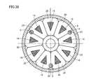
- the plurality of permanent magnets 17 and a plurality of permanent magnets 31are embedded in shroud 12 .
- the number of permanent magnets 31is equal to the number of permanent magnets 17 .
- Permanent magnets 31are magnetized in a circumferential direction (the rotation direction of impeller 10 ).
- Each of the plurality of permanent magnets 17 and each of the plurality of permanent magnets 31are alternately arranged in the Halbach array at equiangular intervals along a single circle.
- permanent magnet 17 having the N-pole oriented to diaphragm 6 and permanent magnet 17 having the S-pole oriented to diaphragm 6are alternately arranged with a gap therebetween at equiangular intervals along a single circle.
- each permanent magnet 31is arranged toward permanent magnet 17 having the N-pole oriented to diaphragm 6
- the S-pole of each permanent magnet 31is arranged toward permanent magnet 17 having the S-pole oriented to diaphragm 6 .
- the plurality of permanent magnets 17have the same shape, and the plurality of permanent magnets 31 have the same shape.
- Permanent magnets 17 and permanent magnets 31may have the same shape or different shapes. In this modification, an attractive force between permanent magnets 17 and magnetic materials 18 can be suppressed and a magnetic flux that causes torque can be increased, thereby minimizing the permanent magnets. Namely, the weight of impeller 10 can be minimized, and energy efficiency can be enhanced even with a wide motor gap.
- FIG. 20illustrates relation between the attractive force and generated torque, when permanent magnets 17 and permanent magnets 31 have the same total weight, and an area ratio of permanent magnet 31 to permanent magnet 17 is changed.
- the area ratio of permanent magnet 31 to permanent magnet 17is set in a range from 1 ⁇ 2 or more and 2 or less, the rotational torque of impeller 10 can be increased while suppressing the attractive force between permanent magnets 17 and magnetic materials 18 to low level. Therefore, an optimal range of the area ratio of permanent magnet 31 to permanent magnet 17 is between 1 ⁇ 2 or more and 2 or less.
- an area ratio between permanent magnet 17 and permanent magnet 31is set to about 5:1 to 3:1.
- the area ratio between permanent magnet 17 and permanent magnet 31can be optimized by being set in a range from 2:1 to 1:2 depending on motor dimensions and the motor gap, in order to strengthen the magnetic field.
- FIG. 21is a block diagram showing yet another modification of the first embodiment. This figure shows an example of a structure where power source supply is switched between during activation of the impeller for rotation and the remaining period.
- power amplifier 27 in FIG. 11is replaced with power amplifiers 32 , 33 and a switch 34 .
- an output signal from motor control circuit 26is provided to power amplifier 32 , and an output voltage from power amplifier 32 is applied to coils 20 via switch 34 , causing current I 0 to flow through coils 20 .
- an output signal from motor control circuit 26is provided to power amplifier 33 , and an output voltage from power amplifier 33 is applied to coils 20 via switch 34 , causing a current to flow through coils 20 .
- FIG. 22 ( a ) to ( c )are time charts illustrating another modification of the first embodiment.
- shroud 11 of impeller 10in an initial state, shroud 11 of impeller 10 is in contact with the inner wall of blood chamber 7 , and impeller 10 is in position PA.
- a predetermined current I 1is fed through coils 20 .
- Motor control circuit 26outputs three-phase control signals in the power distribution system shifted by 120 degrees, for example.
- Power amplifier 27amplifies the three-phase control signals from motor control circuit 26 , and generates three-phase voltages VU, VV and VW shown in FIG. 8 .
- Three-phase voltages VU, VV and VWare applied to first to third coils 20 described with reference to FIG. 7 , respectively. Accordingly, a rotating magnetic field is applied to impeller 10 by current I 1 .
- Current I 1is larger than current I 0 in FIG. 12 , and can activate impeller 10 to rotate even when shroud 11 of impeller 10 is in contact with the inner wall of blood chamber 7 . After activation for rotation is confirmed, coil current I is reduced, and gradually increased to the predetermined rated value. In this manner, even when impeller 10 is closer to position PA, an overcurrent may be fed through coils 20 only when activating impeller 10 to rotate.
- a diamond-like carbon (DLC) coatingmay be formed on at least one of the surface of the inner wall of blood chamber 7 and the surface of diaphragm 6 , and the surface of impeller 10 .
- DLCdiamond-like carbon
- a fluorine-based resin coating, a paraxylylene-based resin coating or the likemay be formed instead of the diamond-like carbon coating.
- FIG. 23is a cross-sectional view showing yet another modification of the first embodiment, which is compared to FIG. 3 .
- the opposite surfaces of permanent magnets 15 and 16have different sizes. While the opposite surfaces of permanent magnets 15 and 16 have the same size in FIG. 3 , by making the opposite surfaces of permanent magnets 15 and 16 have different sizes, the amount of change in attractive force which varies with a distance between the magnets, namely, the negative rigidity can be suppressed to low level, thereby preventing reduction in supporting rigidity for impeller 10 .
- FIG. 24is a cross-sectional view showing yet another modification of the first embodiment, which is compared to FIG. 23 .
- a magnetic material 35is provided on a tip surface of each magnetic material 18 facing permanent magnet 17 .
- a surface of magnetic material 35 facing permanent magnet 17has an area larger than an area of the tip surface of magnetic material 18 .
- an attractive force of magnetic materials 18 and 35 on permanent magnet 17can be increased, thereby enhancing energy efficiency in driving impeller 10 to rotate.
- FIG. 25is a cross-sectional view showing yet another modification of the first embodiment, which is compared to FIG. 23 .
- yoke 19is replaced with a yoke 36
- magnetic material 18is replaced with a magnetic material 37 .
- Yoke 36 and magnetic material 37each include a plurality of steel plates stacked in a length direction of a rotation axis of impeller 10 .
- eddy current loss that occurs in yoke 36 and magnetic material 37can be reduced, thereby enhancing energy efficiency in driving impeller 10 to rotate.
- magnetic material 37may be replaced with a magnetic material 38 including a plurality of steel plates stacked in the rotation direction of impeller 10 .
- magnetic material 37may be replaced with a magnetic material 39 including a plurality of steel plates stacked in the radial direction of impeller 10 .
- the same effect as in the modification in FIG. 25can be obtained in these cases as well.
- each of yoke 19 and magnetic material 18 in FIG. 3may be made of powders of pure iron, soft iron, or ferrosilicon. In this case, iron loss in yoke 19 and magnetic material 18 can be reduced, thereby enhancing energy efficiency in driving impeller 10 to rotate.
- FIG. 28is a cross-sectional view showing yet another modification of the first embodiment, which is compared to FIG. 3 .
- permanent magnet 15is radially divided into two permanent magnets 15 a and 15 b
- permanent magnet 16is radially divided into two permanent magnets 16 a and 16 b . That is, permanent magnets 15 a and 15 b are embedded in shroud 11 , and permanent magnets 16 a and 16 b for attracting permanent magnets 15 a and 15 b , respectively, are embedded in the inner wall of blood chamber 7 facing shroud 11 .
- Permanent magnets 15 a , 15 b , 16 a and 16 bare provided to attract (in other words, bias) impeller 10 to the side opposite to motor chamber 8 , namely, toward blood inlet port 4 .
- FIG. 29 ( a ) and ( b )show structures of permanent magnets 15 a , 15 b , 16 a and 16 b
- FIG. 29 ( a )is a cross-sectional view along the line XXIXA-XXIXA in FIG. 29 ( b ).
- each of permanent magnets 15 a and 15 bis formed in an annular shape, and an outer diameter of permanent magnet 15 a is smaller than an inner diameter of permanent magnet 15 b .
- Permanent magnets 15 a and 15 bare coaxially provided, with center points of both permanent magnets 15 a and 15 b being arranged on a rotation center line of impeller 10 .
- Permanent magnets 15 a and 15 bhave the N-poles oriented in the same direction.
- each of permanent magnets 16 a and 16 bis formed in an arc shape, and two permanent magnets 16 a and two permanent magnets 16 b are aligned in the rotation direction of impeller 10 .
- An outer diameter and an inner diameter of two permanent magnets 16 a arranged in an annular shapeare equal to the outer diameter and the inner diameter of permanent magnet 15 a .
- An outer diameter and an inner diameter of two permanent magnets 16 b arranged in an annular shapeare equal to the outer diameter and the inner diameter of permanent magnet 15 b .
- Permanent magnets 16 a and 16 bhave the N-poles oriented in the same direction.
- the S-poles of permanent magnets 15 a and 15 bface the N-poles of permanent magnets 16 a and 16 b , respectively.
- a gap D 1 between permanent magnets 15 a and 15 b(i.e., a gap between permanent magnets 16 a and 16 b ) is set to be larger than a distance D 2 which is half the radially movable distance of impeller 10 (i.e., a distance which is the difference between an inner diameter of blood chamber 7 and an outer diameter of impeller 10 ) (D 1 >D 2 ).
- the radial supporting rigidity for impeller 10can be increased as compared to an example where only one pair of permanent magnets is provided in the radial direction of impeller 10 .
- a permanent magnetmay be provided in one of shroud 11 and the inner wall of blood chamber 7 , and a magnetic material may be provided in the other. Either a soft magnetic material or a hard magnetic material may be used as the magnetic material.
- opposite surfaces of permanent magnets 15 a and 16 ahave the same size and the opposite surfaces of permanent magnets 15 b and 16 b have the same size in FIG. 28 , it is preferable that the opposite surfaces of permanent magnets 15 a and 16 a have different sizes and the opposite surfaces of permanent magnets 15 b and 16 b have different sizes in order to prevent reduction in rigidity for impeller 10 resulting from the attractive force between permanent magnets 15 a , 15 b and permanent magnets 16 a , 16 b .
- each of permanent magnets 15 a and 15 bis formed in an annular shape and each of permanent magnets 16 a and 16 b is formed in an arc shape, with two permanent magnets 16 a and two permanent magnets 16 b being aligned at equiangular intervals in the rotation direction of impeller 10 in FIG. 29 ( a ) and ( b ), conversely, each of permanent magnets 16 a and 16 b may be formed in an annular shape and each of permanent magnets 15 a and 15 b may be formed in an arc shape, with two permanent magnets 15 a and two permanent magnets 15 b being aligned at equiangular intervals in the rotation direction of impeller 10 .
- each of permanent magnets 15 a and 15 b or each of permanent magnets 16 a and 16 bmay be formed in a shorter arc shape, and a plurality of them may be aligned at equiangular intervals in the rotation direction of impeller 10 .
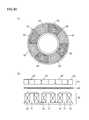
- FIG. 30is a cross-sectional view showing a structure of a pump unit 41 of a centrifugal blood pump apparatus according to a second embodiment of the present invention, which is compared to FIG. 3 .
- FIG. 31is a cross-sectional view along the line XXXI-XXXI in FIG. 30 , which is compared to FIG. 7 .
- pump unit 41is different from pump unit 1 in the first embodiment in that three magnetic sensors S are provided in three portions among four adjacent magnetic materials 18 out of nine magnetic materials 18 .
- Three magnetic sensors Sare arranged to face a path through which the plurality of permanent magnets 17 in impeller 10 pass. When impeller 10 rotates and the S-pole and the N-pole of the plurality of permanent magnets 17 alternately pass near magnetic sensor S, level of an output signal from magnetic sensor S sinusoidally varies as shown in FIG. 32 .
- positional relation between the plurality of permanent magnets 17 and the plurality of magnetic materials 18can be detected, to determine timing for feeding a current through the plurality of coils 20 , and a rotation speed of impeller 10 .
- FIG. 33is a block diagram showing a structure of a controller 42 for controlling pump unit 41 .
- controller 42includes a motor control circuit 43 and a power amplifier 44 .
- Motor control circuit 43outputs three-phase control signals in the power distribution system shifted by 120 degrees, for example, based on output signals from three magnetic sensors S.
- Power amplifier 44amplifies the three-phase control signals from motor control circuit 43 , and generates three-phase voltages VU, VV and VW shown in FIG. 8 .
- Three-phase voltages VU, VV and VWare applied to first to third coils 20 described with reference to FIGS. 7 and 8 , respectively.
- impeller 10rotates with a predetermined rotation speed in the central position of the movable range.
- FIG. 34is a block diagram showing a modification of the second embodiment. This figure shows an example of a structure where power source supply is switched between during activation of the impeller for rotation and the remaining period.
- power amplifier 44 in FIG. 33is replaced with power amplifiers 45 , 46 and switch 47 .
- an output signal from motor control circuit 43is provided to power amplifier 45 , and an output voltage from power amplifier 45 is applied to coils 20 via switch 47 , causing current I 0 to flow through coils 20 .
- an output signal from motor control circuit 43is provided to power amplifier 46
- an output voltage from power amplifier 46is applied to coils 20 via switch 47 , causing a current to flow through coils 20 .
- FIG. 35is a block diagram showing another modification of the second embodiment, which is compared to FIG. 33 .
- a comparator 48 and a position operation unit 49are added into controller 42 in FIG. 33 .
- Comparator 48generates, based on output signals from three magnetic sensors S, three pulse signal strings which indicate timing when the plurality of permanent magnets 17 in impeller 10 pass near three magnetic sensors S.
- Motor control circuit 43generates three-phase control signals in accordance with the three pulse signal strings generated by comparator 48 .
- Power amplifier 44amplifies the three-phase control signals generated by motor control circuit 43 , and generates voltages VU, VV and VW in FIG. 8 .
- Position operation unit 49determines an axial position of impeller 10 in the movable range of impeller 10 based on the amplitudes of the output signals from three magnetic sensors S, as has been described with reference to FIG. 32 , and outputs a signal ⁇ P which indicates the determined position. With signal ⁇ P, whether or not the position of impeller 10 is within a normal range can be determined.
- FIG. 36is a block diagram showing yet another modification of the second embodiment, which is compared to FIG. 35 .
- a rotation speed operation unit 50 and a position determination unit 51are added into controller 42 in FIG. 35 .
- Rotation speed operation unit 50determines a rotation speed of impeller 10 based on output signals from three magnetic sensors S, and outputs a signal ⁇ R which indicates the rotation speed.
- Position determination unit 51determines whether or not the position of impeller 10 is within the normal range based on signal ⁇ P which indicates the position of impeller 10 generated by position operation unit 49 and signal ⁇ R which indicates the rotation speed of impeller 10 generated by rotation speed operation unit 50 , and outputs a signal ⁇ D which indicates a determination result.
- rotation speed operation unit 50may be removed.
- viscosity information on liquidmay be referred to instead of or in addition to the rotation speed of impeller 10 . This is because the hydrodynamic bearing effect of grooves for hydrodynamic bearing 21 and 22 varies with the viscosity of the liquid, causing a change in position of impeller 10 .
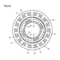
- FIG. 37is a cross-sectional view showing yet another modification of the second embodiment, which is compared to FIG. 31 .
- nine coils 20are divided into three groups each including three coils, and voltages VU, VV and VW in FIG. 8 are applied to first to third coils 20 of each group, respectively.
- First magnetic sensor Sis arranged between first and second coils 20 of the first group.
- Second magnetic sensor Sis arranged between third coil 20 of the first group and first coil 20 of the second group.
- Third magnetic sensor Sis arranged between second and third coils 20 of the second group. Accordingly, an electrical angle between two adjacent of first to third magnetic sensors S is kept at 120 degrees.
- three-phase control signalscan be generated, and an axial position of impeller 10 can be detected. Further, a mechanical angle between two adjacent of first to third magnetic sensors S is 90 degrees, and so a levitation posture of rotating impeller 10 can also be detected.
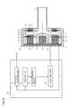
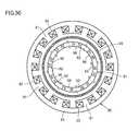
- FIG. 38is a cross-sectional view showing yet another modification of the second embodiment, which is compared to FIG. 31 .
- nine coils 20are divided into three groups each including three coils, and three magnetic sensors S are arranged among the three groups, respectively. Accordingly, a mechanical angle between two adjacent of three magnetic sensors S is 120 degrees, allowing easy operation of a levitation posture of rotating impeller 10 . Timing for feeding a current through nine coils 20 is operated based on an output signal from any one of three magnetic sensors S.
- FIG. 39 ( a )is a bottom view of a rotor 61 of an axial gap type motor according to a third embodiment of the present invention, seen from the side of a diaphragm 60
- FIG. 39 ( b )is a front view showing a substantial part of the axial gap type motor.
- this axial gap type motorhas a structure similar to that of pump unit 1 of the centrifugal blood pump apparatus in the first embodiment, and includes first and second chambers (not shown) partitioned from each other by circular diaphragm 60 .
- the first chamberincludes annular rotor 61 rotatably provided along diaphragm 60
- the second chamberincludes a stator 70 for driving rotor 61 to rotate with diaphragm 60 interposed therebetween.
- Rotor 61includes an annular support member 62 made of a nonmagnetic material, and a plurality of (e.g., eight) permanent magnets 63 fixed to support member 62 .
- the plurality of permanent magnets 63are aligned with a gap therebetween in a rotation direction of rotor 61 .
- Each permanent magnet 63is magnetized in a direction in which a rotation central axis of rotor 61 extends. Two adjacent permanent magnets 63 have magnetic polarities different from each other.
- Stator 70includes a plurality of (e.g., six) magnetic materials 71 arranged to face the plurality of permanent magnets 63 , and a plurality of coils 72 wound around the plurality of magnetic materials 71 , respectively, for generating a rotating magnetic field.
- the plurality of magnetic materials 71are fixed to an annular yoke 73 .
- Rotor 61can be rotated by applying voltages to the plurality of coils 72 by the power distribution system shifted by 120 degrees.
- FIG. 40 ( a ) and ( b )show a comparative example of the third embodiment, which are compared to FIG. 39 ( a ) and ( b ).
- this comparative exampleis different from the third embodiment in that there is no gap between the plurality of permanent magnets 63 .
- the plurality of permanent magnets 63 and an annular magnetic material 64are provided in rotor 61 .
- the plurality of permanent magnets 63are arranged with a gap therebetween at equiangular intervals along a single circle such that adjacent magnetic polarities are different from each other.
- Magnetic material 64serves as a back yoke of the plurality of permanent magnets 63 .
- permanent magnet 63 having the N-pole oriented to diaphragm 60 and permanent magnet 63 having the S-pole oriented to diaphragm 60are alternately arranged with a gap therebetween at equiangular intervals along a single circle.
- a surface of permanent magnet 63 opposite to a surface closer to diaphragm 60is attracted to a surface of annular magnetic material 64 by a magnetic force, so that the plurality of permanent magnets 63 are magnetically coupled to magnetic material 64 .
- a magnetic field around the surfaces of permanent magnets 63 closer to diaphragm 60is stronger than in the third embodiment (see FIG. 16 ). Accordingly, the rotational torque of rotor 61 can be increased while maintaining small device dimensions. Further, copper loss that occurs in coils 72 can be reduced, thereby enhancing energy efficiency in driving rotor 61 to rotate.
- the plurality of permanent magnets 63 and a plurality of permanent magnets 65are provided in rotor 61 .
- the number of permanent magnets 65is equal to the number of permanent magnets 63 .
- the plurality of permanent magnets 65are provided on the side of the plurality of permanent magnets 63 opposite to the side closer to diaphragm 60 , and are aligned in the rotation direction of rotor 61 along the plurality of permanent magnets 63 .
- Each permanent magnet 65is provided correspondingly to a gap between every two adjacent permanent magnets 63 to cover the corresponding gap from the side opposite to diaphragm 60 , and is magnetized in the rotation direction of rotor 61 .
- Each magnetic polarity of each permanent magnet 65is identical to an adjacent magnetic polarity of permanent magnet 65 , and is different from a corresponding magnetic polarity of permanent magnet 63 .
- Each permanent magnet 65is attracted to two corresponding permanent magnets 63 by a magnetic force, so that the plurality of permanent magnets 63 are magnetically coupled to the plurality of permanent magnets 65 .
- a magnetic field around the surfaces of permanent magnets 63 closer to diaphragm 60is stronger than in the modification of FIG. 41 ( a ) and ( b ).
- the rotational torque of rotor 61can be increased while maintaining small device dimensions, thereby enhancing energy efficiency in driving rotor 61 to rotate.
- a magnetic material 66may be inserted in a gap between every two adjacent permanent magnets 65 and each permanent magnet 63 (see FIG. 18 ).
- the plurality of permanent magnets 63 and a plurality of permanent magnets 67are provided in rotor 61 .
- the number of permanent magnets 67is equal to the number of permanent magnets 63 .
- Permanent magnets 67are magnetized in a circumferential direction (the rotation direction of rotor 61 ).
- Each of the plurality of permanent magnets 63 and each of the plurality of permanent magnets 67are alternately arranged in the Halbach array at equiangular intervals along a single circle.
- permanent magnet 63 having the N-pole oriented to diaphragm 60 and permanent magnet 63 having the S-pole oriented to diaphragm 60are alternately arranged with a gap therebetween at equiangular intervals along a single circle.
- the N-pole of each permanent magnet 67is arranged toward permanent magnet 63 having the N-pole oriented to diaphragm 60
- the S-pole of each permanent magnet 67is arranged toward permanent magnet 63 having the S-pole oriented to diaphragm 60 .
- the plurality of permanent magnets 63have the same shape, and the plurality of permanent magnets 67 have the same shape. Permanent magnets 63 and permanent magnets 67 may have the same shape or different shapes.
- the attractive force between permanent magnets 63 and magnetic materials 71 and the magnetic flux that causes torquecan be adjusted.
- the area ratio of permanent magnet 67 to permanent magnet 63is set in a range from 1 ⁇ 2 or more and 2 or less, the rotational torque of rotor 61 can be increased while suppressing the attractive force between permanent magnets 63 and magnetic materials 71 to low level. Therefore, an optimal range of the area ratio of permanent magnet 67 to permanent magnet 63 is between 1 ⁇ 2 or more and 2 or less.
- FIG. 45is a plan view showing a substantial part of a radial gap type motor according to a fourth embodiment of the present invention.
- this radial gap type motorhas a structure similar to that of the axial gap type motor in FIG. 39 , and includes first and second chambers (not shown) partitioned from each other by a cylindrical diaphragm 80 .
- the first chamber on an inner side relative to diaphragm 80includes a cylindrical rotor 81 rotatably provided along diaphragm 80
- the second chamber on an outer side relative to diaphragm 80includes a stator 90 for driving rotor 81 to rotate with diaphragm 80 interposed therebetween.
- Rotor 81includes a cylindrical support member (not shown) made of a nonmagnetic material, and a plurality of (e.g., eight) permanent magnets 82 fixed to the support member.
- the plurality of permanent magnets 82are aligned with a gap therebetween in a rotation direction of rotor 81 .
- Each permanent magnet 82is magnetized in a direction (radial direction) orthogonal to the rotation direction of rotor 81 .
- Two adjacent permanent magnets 82have magnetic polarities different from each other.
- Stator 90includes a plurality of (e.g., six) magnetic materials 91 arranged to face the plurality of permanent magnets 82 , and a plurality of coils 92 wound around the plurality of magnetic materials 91 , respectively, for generating a rotating magnetic field.
- the plurality of magnetic materials 91are fixed to an inner circumferential surface of a cylindrical yoke 93 .
- Rotor 81can be rotated by applying voltages to the plurality of coils 92 by the power distribution system shifted by 120 degrees.
- FIG. 46shows a comparative example of the fourth embodiment, which is compared to FIG. 45 .
- this comparative exampleis different from the fourth embodiment in that there is no gap between the plurality of permanent magnets 82 .
- the plurality of permanent magnets 82 and a cylindrical magnetic material 83are provided in rotor 81 .
- the plurality of permanent magnets 82are arranged with a gap therebetween at equiangular intervals along a single circle such that adjacent magnetic polarities are different from each other.
- Magnetic material 83serves as a back yoke of the plurality of permanent magnets 82 .
- permanent magnet 82 having the N-pole oriented to diaphragm 80 and permanent magnet 82 having the S-pole oriented to diaphragm 80are alternately arranged with a gap therebetween at equiangular intervals along a single circle.
- a surface of permanent magnet 82 opposite to a surface closer to diaphragm 80is attracted to an outer circumferential surface of cylindrical magnetic material 83 by a magnetic force, so that the plurality of permanent magnets 82 are magnetically coupled to magnetic material 83 .
- a magnetic field around the surfaces of permanent magnets 82 closer to diaphragm 80is stronger than in the fourth embodiment (see FIG. 16 ). Accordingly, the rotational torque of rotor 81 can be increased while maintaining small device dimensions. Further, copper loss that occurs in coils 92 can be reduced, thereby enhancing energy efficiency in driving rotor 81 to rotate.
- the plurality of permanent magnets 82 and a plurality of permanent magnets 84are provided in rotor 81 .
- the number of permanent magnets 84is equal to the number of permanent magnets 82 .
- the plurality of permanent magnets 84are provided on the side of the plurality of permanent magnets 82 opposite to the side closer to diaphragm 80 , and are aligned in the rotation direction of rotor 81 along the plurality of permanent magnets 82 .
- Each permanent magnet 84is provided correspondingly to a gap between every two adjacent permanent magnets 82 to cover the corresponding gap from the side opposite to diaphragm 80 , and is magnetized in the rotation direction of rotor 81 .
- Each magnetic polarity of each permanent magnet 84is identical to an adjacent magnetic polarity of permanent magnet 84 , and is different from a corresponding magnetic polarity of permanent magnet 82 .
- Each permanent magnet 84is attracted to two corresponding permanent magnets 82 by a magnetic force, so that the plurality of permanent magnets 82 are magnetically coupled to the plurality of permanent magnets 84 .
- a magnetic field around the surfaces of permanent magnets 82 closer to diaphragm 80is stronger than in the modification of FIG. 47 (see FIG. 17 ).
- the rotational torque of rotor 81can be increased while maintaining small device dimensions, thereby enhancing energy efficiency in driving rotor 81 to rotate.
- a magnetic material 85may be inserted in a gap between every two adjacent permanent magnets 84 and each permanent magnet 82 (see FIG. 18 ).
- the plurality of permanent magnets 82 and a plurality of permanent magnets 86are provided in rotor 81 .
- the number of permanent magnets 86is equal to the number of permanent magnets 82 .
- Permanent magnets 86are magnetized in a circumferential direction (the rotation direction of rotor 81 ).
- Each of the plurality of permanent magnets 82 and each of the plurality of permanent magnets 86are alternately arranged in the Halbach array at equiangular intervals along a single circle.
- permanent magnet 82 having the N-pole oriented to diaphragm 80 and permanent magnet 82 having the S-pole oriented to diaphragm 80are alternately arranged with a gap therebetween at equiangular intervals along a single circle.
- the N-pole of each permanent magnet 86is arranged toward permanent magnet 82 having the N-pole oriented to diaphragm 80
- the S-pole of each permanent magnet 86is arranged toward permanent magnet 82 having the S-pole oriented to diaphragm 80 .
- the plurality of permanent magnets 82have the same shape, and the plurality of permanent magnets 86 have the same shape.
- Permanent magnets 82 and permanent magnets 86may have the same shape or different shapes.
- the attractive force between permanent magnets 82 and magnetic materials 91 and the magnetic flux that causes torquecan be adjusted.
- the area ratio of permanent magnet 86 to permanent magnet 82is set in a range from 1 ⁇ 2 or more and 2 or less, the rotational torque of rotor 81 can be increased while suppressing the attractive force between permanent magnets 82 and magnetic materials 91 to low level. Therefore, an optimal range of the area ratio of permanent magnet 86 to permanent magnet 82 is between 1 ⁇ 2 or more and 2 or less.
Landscapes
- Engineering & Computer Science (AREA)
- Health & Medical Sciences (AREA)
- Mechanical Engineering (AREA)
- Heart & Thoracic Surgery (AREA)
- General Health & Medical Sciences (AREA)
- Power Engineering (AREA)
- Biomedical Technology (AREA)
- Hematology (AREA)
- Life Sciences & Earth Sciences (AREA)
- Animal Behavior & Ethology (AREA)
- Cardiology (AREA)
- Public Health (AREA)
- Veterinary Medicine (AREA)
- Anesthesiology (AREA)
- General Engineering & Computer Science (AREA)
- Physics & Mathematics (AREA)
- Fluid Mechanics (AREA)
- Electromagnetism (AREA)
- External Artificial Organs (AREA)
- Structures Of Non-Positive Displacement Pumps (AREA)
- Motor Or Generator Frames (AREA)
- Connection Of Motors, Electrical Generators, Mechanical Devices, And The Like (AREA)
- Permanent Magnet Type Synchronous Machine (AREA)
Abstract
Description
- PTL 1: Japanese Patent Laying-Open No. 2004-209240
- PTL 2: Japanese Patent Laying-Open No. 2006-167173
- PTL 3: Japanese Patent Laying-Open No. 4-91396
- PTL 4: Japanese Utility Model Laying-Open No. 6-53790
Claims (10)
Applications Claiming Priority (3)
| Application Number | Priority Date | Filing Date | Title |
|---|---|---|---|
| JP2009-176498 | 2009-07-29 | ||
| JP2009176498 | 2009-07-29 | ||
| PCT/JP2010/061439WO2011013483A1 (en) | 2009-07-29 | 2010-07-06 | Rotation drive device and centrifugal pump device |
Publications (2)
| Publication Number | Publication Date |
|---|---|
| US20120130152A1 US20120130152A1 (en) | 2012-05-24 |
| US8821365B2true US8821365B2 (en) | 2014-09-02 |
Family
ID=43529146
Family Applications (1)
| Application Number | Title | Priority Date | Filing Date |
|---|---|---|---|
| US13/387,637Expired - Fee RelatedUS8821365B2 (en) | 2009-07-29 | 2010-07-06 | Rotation drive device and centrifugal pump apparatus using the same |
Country Status (4)
| Country | Link |
|---|---|
| US (1) | US8821365B2 (en) |
| EP (3) | EP3832861A1 (en) |
| JP (1) | JP5656835B2 (en) |
| WO (1) | WO2011013483A1 (en) |
Cited By (25)
| Publication number | Priority date | Publication date | Assignee | Title |
|---|---|---|---|---|
| US20150010415A1 (en)* | 2012-01-18 | 2015-01-08 | Thoratec Corporation | Centrifugal pump device |
| US20150192122A1 (en)* | 2012-12-12 | 2015-07-09 | Marel A/S | Rotary Fluid Machine and Associated Method of Operation |
| US20150244219A1 (en)* | 2014-02-26 | 2015-08-27 | Yasa Motors Limited | Asymmetric machines |
| US20160369805A1 (en)* | 2013-06-21 | 2016-12-22 | Heraeus Deutschland GmbH & Co. KG | Pump housing made of a magnetic and a non-magnetic material |
| US20170016449A1 (en)* | 2015-07-14 | 2017-01-19 | Hamilton Sundstrand Corporation | Axial-flux induction motor pump |
| US9556873B2 (en) | 2013-02-27 | 2017-01-31 | Tc1 Llc | Startup sequence for centrifugal pump with levitated impeller |
| US9623161B2 (en) | 2014-08-26 | 2017-04-18 | Tc1 Llc | Blood pump and method of suction detection |
| US9638202B2 (en) | 2010-09-14 | 2017-05-02 | Tc1 Llc | Centrifugal pump apparatus |
| US9709061B2 (en) | 2013-01-24 | 2017-07-18 | Tc1 Llc | Impeller position compensation using field oriented control |
| US9850906B2 (en) | 2011-03-28 | 2017-12-26 | Tc1 Llc | Rotation drive device and centrifugal pump apparatus employing same |
| US10052420B2 (en) | 2013-04-30 | 2018-08-21 | Tc1 Llc | Heart beat identification and pump speed synchronization |
| US20180245596A1 (en)* | 2016-07-26 | 2018-08-30 | RELIAX MOTORES SA de CV | Integrated electric motor and pump assembly |
| US10117983B2 (en) | 2015-11-16 | 2018-11-06 | Tc1 Llc | Pressure/flow characteristic modification of a centrifugal pump in a ventricular assist device |
| US10166318B2 (en) | 2015-02-12 | 2019-01-01 | Tc1 Llc | System and method for controlling the position of a levitated rotor |
| US10245361B2 (en) | 2015-02-13 | 2019-04-02 | Tc1 Llc | Impeller suspension mechanism for heart pump |
| US10371152B2 (en) | 2015-02-12 | 2019-08-06 | Tc1 Llc | Alternating pump gaps |
| US10506935B2 (en) | 2015-02-11 | 2019-12-17 | Tc1 Llc | Heart beat identification and pump speed synchronization |
| US10514044B2 (en) | 2013-06-21 | 2019-12-24 | Heraeus Deutschland GmbH & Co. KG | Pump housing of two different sinterable materials |
| US10655631B2 (en) | 2014-03-24 | 2020-05-19 | Heraeus Deutschland GmbH & Co. KG | Pump housing made from at least three different sinterable materials |
| US11712501B2 (en) | 2019-11-12 | 2023-08-01 | Fresenius Medical Care Deutschland Gmbh | Blood treatment systems |
| US11730871B2 (en) | 2019-11-12 | 2023-08-22 | Fresenius Medical Care Deutschland Gmbh | Blood treatment systems |
| US11752247B2 (en) | 2019-11-12 | 2023-09-12 | Fresenius Medical Care Deutschland Gmbh | Blood treatment systems |
| US11925736B2 (en) | 2019-11-12 | 2024-03-12 | Fresenius Medical Care Deutschland Gmbh | Blood treatment systems |
| US12285553B2 (en) | 2019-11-12 | 2025-04-29 | Fresenius Medical Care Deutschland Gmbh | Blood treatment systems |
| US12329890B2 (en) | 2019-11-12 | 2025-06-17 | Fresenius Medical Care Deutschland Gmbh | Blood treatment systems |
Families Citing this family (46)
| Publication number | Priority date | Publication date | Assignee | Title |
|---|---|---|---|---|
| JP5093599B2 (en)* | 2008-04-25 | 2012-12-12 | 国立大学法人 東京大学 | Viscosity / elasticity measuring apparatus and method |
| JP5171953B2 (en) | 2008-06-23 | 2013-03-27 | テルモ株式会社 | Blood pump device |
| EP2372160B1 (en) | 2008-12-08 | 2014-07-30 | Thoratec Corporation | Centrifugal pump device |
| JP5378010B2 (en) | 2009-03-05 | 2013-12-25 | ソラテック コーポレーション | Centrifugal pump device |
| CN102341600B (en) | 2009-03-06 | 2014-12-10 | 胸腔科技有限公司 | Centrifugal pump device |
| US8821365B2 (en) | 2009-07-29 | 2014-09-02 | Thoratec Corporation | Rotation drive device and centrifugal pump apparatus using the same |
| JP5443197B2 (en) | 2010-02-16 | 2014-03-19 | ソラテック コーポレーション | Centrifugal pump device |
| JP5572832B2 (en) | 2010-03-26 | 2014-08-20 | ソーラテック コーポレイション | Centrifugal blood pump device |
| JP5681403B2 (en) | 2010-07-12 | 2015-03-11 | ソーラテック コーポレイション | Centrifugal pump device |
| JP5660942B2 (en)* | 2011-03-16 | 2015-01-28 | 株式会社久保田鉄工所 | Electric pump and rotor for electric pump |
| JP2012205349A (en)* | 2011-03-24 | 2012-10-22 | Ntn Corp | Rotary drive device and centrifugal pump device using the same |
| WO2013082621A1 (en) | 2011-12-03 | 2013-06-06 | Indiana University Research And Technology Corporation | Cavopulmonary viscous impeller assist device and method |
| WO2014036006A2 (en)* | 2012-08-27 | 2014-03-06 | Ecotech Marine, Llc | Electromagnetic circulation pump |
| EP2719403B1 (en)* | 2012-10-12 | 2016-09-28 | Abiomed Europe GmbH | Centrifugal blood pump |
| US20140309481A1 (en)* | 2013-04-11 | 2014-10-16 | Thoratec Corporation | Rotary pump with levitated impeller having thrust bearing for improved startup |
| US9713663B2 (en) | 2013-04-30 | 2017-07-25 | Tc1 Llc | Cardiac pump with speed adapted for ventricle unloading |
| JP6503950B2 (en)* | 2015-07-13 | 2019-04-24 | 株式会社デンソー | Rotor and brushless motor |
| CA3066361A1 (en) | 2017-06-07 | 2018-12-13 | Shifamed Holdings, Llc | Intravascular fluid movement devices, systems, and methods of use |
| WO2019094963A1 (en) | 2017-11-13 | 2019-05-16 | Shifamed Holdings, Llc | Intravascular fluid movement devices, systems, and methods of use |
| DE102018201030B4 (en) | 2018-01-24 | 2025-10-16 | Kardion Gmbh | Magnetic dome element with magnetic bearing function |
| CN112004563B (en) | 2018-02-01 | 2024-08-06 | 施菲姆德控股有限责任公司 | Intravascular blood pump and methods of use and manufacture |
| DE102018207611A1 (en) | 2018-05-16 | 2019-11-21 | Kardion Gmbh | Rotor bearing system |
| DE102018207575A1 (en) | 2018-05-16 | 2019-11-21 | Kardion Gmbh | Magnetic face turning coupling for the transmission of torques |
| EP3574932A1 (en)* | 2018-05-28 | 2019-12-04 | Berlin Heart GmbH | Blood pump |
| DE102018208538A1 (en) | 2018-05-30 | 2019-12-05 | Kardion Gmbh | Intravascular blood pump and process for the production of electrical conductors |
| DE102018208539A1 (en) | 2018-05-30 | 2019-12-05 | Kardion Gmbh | A motor housing module for sealing an engine compartment of a motor of a cardiac assist system and cardiac assistance system and method for mounting a cardiac assist system |
| DE102018208541A1 (en) | 2018-05-30 | 2019-12-05 | Kardion Gmbh | Axial pump for a cardiac assist system and method of making an axial pump for a cardiac assist system |
| DE102018208550A1 (en) | 2018-05-30 | 2019-12-05 | Kardion Gmbh | A lead device for directing blood flow to a cardiac assist system, cardiac assist system, and method of making a lead device |
| DE102018210076A1 (en) | 2018-06-21 | 2019-12-24 | Kardion Gmbh | Method and device for detecting a state of wear of a cardiac support system, method and device for operating a cardiac support system and cardiac support system |
| DE102018210058A1 (en) | 2018-06-21 | 2019-12-24 | Kardion Gmbh | Stator blade device for guiding the flow of a fluid flowing out of an outlet opening of a heart support system, heart support system with stator blade device, method for operating a stator blade device and manufacturing method |
| DE102018211327A1 (en) | 2018-07-10 | 2020-01-16 | Kardion Gmbh | Impeller for an implantable vascular support system |
| DE102018212153A1 (en) | 2018-07-20 | 2020-01-23 | Kardion Gmbh | Inlet line for a pump unit of a cardiac support system, cardiac support system and method for producing an inlet line for a pump unit of a cardiac support system |
| US12161857B2 (en) | 2018-07-31 | 2024-12-10 | Shifamed Holdings, Llc | Intravascular blood pumps and methods of use |
| CN112654389A (en) | 2018-08-07 | 2021-04-13 | 开迪恩有限公司 | Bearing device for a cardiac support system and method for flushing an intermediate space in a bearing device for a cardiac support system |
| WO2020073047A1 (en) | 2018-10-05 | 2020-04-09 | Shifamed Holdings, Llc | Intravascular blood pumps and methods of use |
| WO2021011473A1 (en) | 2019-07-12 | 2021-01-21 | Shifamed Holdings, Llc | Intravascular blood pumps and methods of manufacture and use |
| US11654275B2 (en) | 2019-07-22 | 2023-05-23 | Shifamed Holdings, Llc | Intravascular blood pumps with struts and methods of use and manufacture |
| WO2021034642A1 (en)* | 2019-08-16 | 2021-02-25 | Regents Of The University Of Minnesota | Integrated electric-to-hydraulic conversion machine |
| WO2021062265A1 (en) | 2019-09-25 | 2021-04-01 | Shifamed Holdings, Llc | Intravascular blood pump systems and methods of use and control thereof |
| EP4501393A3 (en) | 2019-09-25 | 2025-04-09 | Shifamed Holdings, LLC | Catheter blood pumps and collapsible pump housings |
| US12121713B2 (en) | 2019-09-25 | 2024-10-22 | Shifamed Holdings, Llc | Catheter blood pumps and collapsible blood conduits |
| EP4072650A4 (en) | 2019-12-11 | 2024-01-10 | Shifamed Holdings, LLC | Descending aorta and vena cava blood pumps |
| DE102020102474A1 (en) | 2020-01-31 | 2021-08-05 | Kardion Gmbh | Pump for conveying a fluid and method for manufacturing a pump |
| US11648393B2 (en)* | 2020-03-17 | 2023-05-16 | Heartware, Inc. | Implantable blood pump with thrombus diverter |
| CN112546425B (en)* | 2020-10-29 | 2021-07-23 | 苏州心擎医疗技术有限公司 | Magnetic levitation motor and magnetic levitation blood pump |
| CN115089869B (en)* | 2022-06-28 | 2025-07-01 | 重庆凯磁医疗技术有限公司 | Mixed magnetic blood pump |
Citations (203)
| Publication number | Priority date | Publication date | Assignee | Title |
|---|---|---|---|---|
| US1093868A (en) | 1912-03-11 | 1914-04-21 | Henry W Jacobs | Means for forming couplings or joints. |
| US2684035A (en) | 1947-10-02 | 1954-07-20 | Philip G Kemp | Fluid pump |
| US3510229A (en) | 1968-07-23 | 1970-05-05 | Maytag Co | One-way pump |
| US3960468A (en) | 1946-07-16 | 1976-06-01 | The United States Of America As Represented By The United States Energy Research And Development Administration | Fluid lubricated bearing assembly |
| US4149535A (en) | 1976-05-06 | 1979-04-17 | Gist-Brocades N.V. | Catheter holding device |
| US4382199A (en) | 1980-11-06 | 1983-05-03 | Nu-Tech Industries, Inc. | Hydrodynamic bearing system for a brushless DC motor |
| US4392836A (en) | 1980-05-21 | 1983-07-12 | Kanto Seiki Co., Ltd. | Device for connecting speedometer to flexible shaft |
| US4507048A (en) | 1979-03-16 | 1985-03-26 | Jacques Belenger | Centrifugal clinical blood pump |
| US4540402A (en) | 1982-04-20 | 1985-09-10 | Karl Aigner | Double perfusion catheter |
| US4549860A (en) | 1983-04-04 | 1985-10-29 | Yakich Sam S | Blood pump improvements |
| US4686982A (en) | 1985-06-19 | 1987-08-18 | John Nash | Spiral wire bearing for rotating wire drive catheter |
| US4688998A (en) | 1981-03-18 | 1987-08-25 | Olsen Don B | Magnetically suspended and rotated impellor pump apparatus and method |
| US4753221A (en) | 1986-10-22 | 1988-06-28 | Intravascular Surgical Instruments, Inc. | Blood pumping catheter and method of use |
| US4769006A (en) | 1985-05-13 | 1988-09-06 | Kos Medical Technologies, Ltd. | Hydrodynamically propelled pacing catheter |
| US4790843A (en) | 1986-06-16 | 1988-12-13 | Baxter Travenol Laboratories, Inc. | Prosthetic heart valve assembly |
| US4806080A (en) | 1983-07-06 | 1989-02-21 | Ebara Corporation | Pump with shaftless impeller |
| US4817586A (en) | 1987-11-24 | 1989-04-04 | Nimbus Medical, Inc. | Percutaneous bloom pump with mixed-flow output |
| US4846152A (en) | 1987-11-24 | 1989-07-11 | Nimbus Medical, Inc. | Single-stage axial flow blood pump |
| US4895557A (en) | 1987-12-07 | 1990-01-23 | Nimbus Medical, Inc. | Drive mechanism for powering intravascular blood pumps |
| US4900227A (en) | 1988-06-14 | 1990-02-13 | Thomson-Brandt-Armements | Wind power of hydraulic power machine with axial feed, radial outflow, and variable geometry vanes, and projectiles fitted with wind power or hydraulic power machines of this type |
| US4902272A (en) | 1987-06-17 | 1990-02-20 | Abiomed Cardiovascular, Inc. | Intra-arterial cardiac support system |
| US4906229A (en) | 1988-05-03 | 1990-03-06 | Nimbus Medical, Inc. | High-frequency transvalvular axisymmetric blood pump |
| US4908012A (en) | 1988-08-08 | 1990-03-13 | Nimbus Medical, Inc. | Chronic ventricular assist system |
| US4919647A (en) | 1988-10-13 | 1990-04-24 | Kensey Nash Corporation | Aortically located blood pumping catheter and method of use |
| US4930997A (en) | 1987-08-19 | 1990-06-05 | Bennett Alan N | Portable medical suction device |
| US4944722A (en) | 1989-02-23 | 1990-07-31 | Nimbus Medical, Inc. | Percutaneous axial flow blood pump |
| US4957504A (en) | 1988-12-02 | 1990-09-18 | Chardack William M | Implantable blood pump |
| US4964864A (en) | 1988-09-27 | 1990-10-23 | American Biomed, Inc. | Heart assist pump |
| US4969865A (en) | 1989-01-09 | 1990-11-13 | American Biomed, Inc. | Helifoil pump |
| US4985014A (en) | 1989-07-11 | 1991-01-15 | Orejola Wilmo C | Ventricular venting loop |
| US4995857A (en) | 1989-04-07 | 1991-02-26 | Arnold John R | Left ventricular assist device and method for temporary and permanent procedures |
| US5021048A (en) | 1989-08-04 | 1991-06-04 | Medtronic, Inc. | Blood pump drive system |
| US5078741A (en) | 1986-10-12 | 1992-01-07 | Life Extenders Corporation | Magnetically suspended and rotated rotor |
| US5092879A (en) | 1988-02-17 | 1992-03-03 | Jarvik Robert K | Intraventricular artificial hearts and methods of their surgical implantation and use |
| US5092844A (en) | 1990-04-10 | 1992-03-03 | Mayo Foundation For Medical Education And Research | Intracatheter perfusion pump apparatus and method |
| US5106263A (en) | 1989-09-22 | 1992-04-21 | Jidosha Denki Kogyo K.K. | Centrifugal pump with high efficiency impeller |
| US5106273A (en) | 1990-03-07 | 1992-04-21 | Alcatel Cit | Vacuum pump for producing a clean molecular vacuum |
| US5106372A (en) | 1991-05-03 | 1992-04-21 | Sherwood Medical Company | Single use syringe |
| US5129883A (en) | 1990-07-26 | 1992-07-14 | Michael Black | Catheter |
| US5145333A (en) | 1990-03-01 | 1992-09-08 | The Cleveland Clinic Foundation | Fluid motor driven blood pump |
| US5147186A (en) | 1989-08-04 | 1992-09-15 | Bio Medicus, Inc. | Blood pump drive system |
| US5190528A (en) | 1990-10-19 | 1993-03-02 | Boston University | Percutaneous transseptal left atrial cannulation system |
| US5201679A (en) | 1991-12-13 | 1993-04-13 | Attwood Corporation | Marine propeller with breakaway hub |
| US5211546A (en) | 1990-05-29 | 1993-05-18 | Nu-Tech Industries, Inc. | Axial flow blood pump with hydrodynamically suspended rotor |
| US5275580A (en) | 1990-03-08 | 1994-01-04 | Kenji Yamazaki | Auxiliary artificial heart of the embedded-in-body type |
| US5290227A (en) | 1992-08-06 | 1994-03-01 | Pasque Michael K | Method of implanting blood pump in ascending aorta or main pulmonary artery |
| US5300112A (en) | 1992-07-14 | 1994-04-05 | Aai Corporation | Articulated heart pump |
| US5306295A (en) | 1992-04-30 | 1994-04-26 | University Of Utah Research Foundation | Electrohydraulic heart with septum mounted pump |
| US5312341A (en) | 1992-08-14 | 1994-05-17 | Wayne State University | Retaining apparatus and procedure for transseptal catheterization |
| US5332374A (en)* | 1992-12-30 | 1994-07-26 | Ralph Kricker | Axially coupled flat magnetic pump |
| US5346458A (en) | 1990-06-25 | 1994-09-13 | Klaus Affeld | Electrohydraulic energy converter for cardiac assist devices and artificial hearts |
| US5354331A (en) | 1992-07-15 | 1994-10-11 | Schachar Ronald A | Treatment of presbyopia and other eye disorders |
| US5360445A (en) | 1991-11-06 | 1994-11-01 | International Business Machines Corporation | Blood pump actuator |
| US5370509A (en) | 1989-05-08 | 1994-12-06 | The Cleveland Clinic Foundation | Sealless rotodynamic pump with fluid bearing |
| US5376114A (en) | 1992-10-30 | 1994-12-27 | Jarvik; Robert | Cannula pumps for temporary cardiac support and methods of their application and use |
| US5449342A (en) | 1991-09-30 | 1995-09-12 | Nippon Zeon Co., Ltd. | Apparatus for assisting blood circulation |
| US5504978A (en) | 1994-07-15 | 1996-04-09 | Meyer, Iii; Harold A. | Locking clamp assembly |
| US5507629A (en) | 1994-06-17 | 1996-04-16 | Jarvik; Robert | Artificial hearts with permanent magnet bearings |
| US5533957A (en) | 1994-05-06 | 1996-07-09 | Trustees Of Boston University | Method of tissue retroperfusion |
| US5569111A (en) | 1994-10-11 | 1996-10-29 | The United States Of America As Represented By The Secretary Of The Navy | Permanent magnet torque/force transfer apparatus |
| US5575630A (en) | 1995-08-08 | 1996-11-19 | Kyocera Corporation | Blood pump having magnetic attraction |
| US5595762A (en) | 1992-11-30 | 1997-01-21 | Laboratoires Virbac | Stabilized pulverulent active agents, compositions containing them, process for obtaining them and their applications |
| US5611679A (en) | 1996-04-22 | 1997-03-18 | Eastman Kodak Company | Corrosion-resistant pump |
| US5613935A (en) | 1994-12-16 | 1997-03-25 | Jarvik; Robert | High reliability cardiac assist system |
| US5643226A (en) | 1993-02-24 | 1997-07-01 | Minnesota Mining And Manufacturing | Low velocity aortic cannula |
| US5678306A (en) | 1993-11-10 | 1997-10-21 | The United States Of America As Represented By The Administrator Of The National Aeronautics And Space Administration | Method for reducing pumping damage to blood |
| WO1997042413A1 (en) | 1996-05-03 | 1997-11-13 | University Of Utah | Hybrid magnetically suspended and rotated centrifugal pumping apparatus and method |
| US5695471A (en) | 1996-02-20 | 1997-12-09 | Kriton Medical, Inc. | Sealless rotary blood pump with passive magnetic radial bearings and blood immersed axial bearings |
| US5725357A (en) | 1995-04-03 | 1998-03-10 | Ntn Corporation | Magnetically suspended type pump |
| US5738649A (en) | 1996-04-16 | 1998-04-14 | Cardeon Corporation | Peripheral entry biventricular catheter system for providing access to the heart for cardiopulmonary surgery or for prolonged circulatory support of the heart |
| US5746709A (en) | 1996-04-25 | 1998-05-05 | Medtronic, Inc. | Intravascular pump and bypass assembly and method for using the same |
| US5746575A (en) | 1993-06-25 | 1998-05-05 | Baxter International, Inc. | Blood pump as centrifugal pump |
| US5749855A (en) | 1992-09-02 | 1998-05-12 | Reitan; Oyvind | Catheter pump |
| US5776111A (en) | 1996-11-07 | 1998-07-07 | Medical Components, Inc. | Multiple catheter assembly |
| US5800559A (en) | 1994-02-01 | 1998-09-01 | Howmedica Inc. | Coated femoral stem prosthesis |
| US5807311A (en) | 1996-11-29 | 1998-09-15 | Palestrant; Aubrey M. | Dialysis catheter having rigid and collapsible lumens and related method |
| US5814011A (en) | 1996-04-25 | 1998-09-29 | Medtronic, Inc. | Active intravascular lung |
| US5824069A (en) | 1996-09-13 | 1998-10-20 | Medtronic, Inc. | Prosthetic heart valve with suturing member having non-uniform radial width |
| US5851174A (en) | 1996-09-17 | 1998-12-22 | Robert Jarvik | Cardiac support device |
| US5853394A (en) | 1994-05-09 | 1998-12-29 | Tolkoff; Marc Joshua | Catheter |
| US5868702A (en) | 1991-07-16 | 1999-02-09 | Heartport, Inc. | System for cardiac procedures |
| US5868703A (en) | 1996-04-10 | 1999-02-09 | Endoscopic Technologies, Inc. | Multichannel catheter |
| US5890883A (en) | 1997-03-19 | 1999-04-06 | The Cleveland Clinic Foundation | Rotodynamic pump with non-circular hydrodynamic bearing journal |
| US5911685A (en) | 1996-04-03 | 1999-06-15 | Guidant Corporation | Method and apparatus for cardiac blood flow assistance |
| US5924975A (en) | 1995-08-30 | 1999-07-20 | International Business Machines Corporation | Linear pump |
| US5924848A (en) | 1995-06-01 | 1999-07-20 | Advanced Bionics, Inc. | Blood pump having radial vanes with enclosed magnetic drive components |
| US5938412A (en) | 1995-06-01 | 1999-08-17 | Advanced Bionics, Inc. | Blood pump having rotor with internal bore for fluid flow |
| US5941813A (en) | 1996-07-23 | 1999-08-24 | Cardiotools Herzchirurgietechnik Gmbh | Cardiac assist device |
| US5947703A (en) | 1996-01-31 | 1999-09-07 | Ntn Corporation | Centrifugal blood pump assembly |
| US5951263A (en) | 1995-04-19 | 1999-09-14 | Nimbus, Inc. | Implantable electric axial-flow blood pump with blood-cooled bearing |
| US5964694A (en) | 1997-04-02 | 1999-10-12 | Guidant Corporation | Method and apparatus for cardiac blood flow assistance |
| US6004269A (en) | 1993-07-01 | 1999-12-21 | Boston Scientific Corporation | Catheters for imaging, sensing electrical potentials, and ablating tissue |
| US6007479A (en) | 1996-07-08 | 1999-12-28 | H.D.S. Systems Ltd. | Heart assist system and method |
| US6042347A (en) | 1998-07-27 | 2000-03-28 | Scholl; Frank G. | Pedia-cadio pump |
| US6066086A (en) | 1996-11-01 | 2000-05-23 | Nimbus, Inc. | Speed control system for implanted blood pumps |
| US6071093A (en) | 1996-10-18 | 2000-06-06 | Abiomed, Inc. | Bearingless blood pump and electronic drive system |
| US6080133A (en) | 1996-02-20 | 2000-06-27 | Kriton Medical, Inc. | Sealless rotary blood pump |
| US6083260A (en) | 1997-07-11 | 2000-07-04 | A-Med Systems, Inc. | Reverse flow transport pump and organ stabilization apparatus including related methods |
| US6086527A (en) | 1998-04-02 | 2000-07-11 | Scimed Life Systems, Inc. | System for treating congestive heart failure |
| US6123726A (en) | 1997-07-25 | 2000-09-26 | Seiko Epson Corporation | Portable drive system for artificial heart |
| US6123659A (en) | 1999-01-26 | 2000-09-26 | Nimbus Inc. | Blood pump with profiled outflow region |
| US6143025A (en) | 1996-07-29 | 2000-11-07 | Edwards Lifesciences Corporation | Suture rings for rotatable artificial heart valves |
| US6142752A (en) | 1997-09-05 | 2000-11-07 | Ntn Corporation | Centrifugal fluid pump assembly |
| US6146325A (en) | 1999-06-03 | 2000-11-14 | Arrow International, Inc. | Ventricular assist device |
| US6149683A (en) | 1998-10-05 | 2000-11-21 | Kriton Medical, Inc. | Power system for an implantable heart pump |
| US6158984A (en) | 1998-12-28 | 2000-12-12 | Kriton Medical, Inc. | Rotary blood pump with ceramic members |
| US6176822B1 (en) | 1998-03-31 | 2001-01-23 | Impella Cardiotechnik Gmbh | Intracardiac blood pump |
| US6176848B1 (en) | 1996-04-04 | 2001-01-23 | Impella Cardiotechnik Gmbh | Intravascular blood pump |
| US6190304B1 (en) | 1999-07-13 | 2001-02-20 | University Of North Texas Health Science Center At Fort Worth | Enhanced intra-aortic balloon assist device |
| US6200260B1 (en) | 1997-10-09 | 2001-03-13 | Fore Flow Corporation | Implantable heart assist system |
| US6206659B1 (en) | 1995-06-01 | 2001-03-27 | Advanced Bionics, Inc. | Magnetically driven rotor for blood pump |
| US6234772B1 (en) | 1999-04-28 | 2001-05-22 | Kriton Medical, Inc. | Rotary blood pump |
| US6245007B1 (en) | 1999-01-28 | 2001-06-12 | Terumo Cardiovascular Systems Corporation | Blood pump |
| US6247892B1 (en) | 1999-07-26 | 2001-06-19 | Impsa International Inc. | Continuous flow rotary pump |
| US6254359B1 (en) | 1996-05-10 | 2001-07-03 | The United States Of America As Represented By The Administrator Of The National Aeronautics And Space Administration | Method for providing a jewel bearing for supporting a pump rotor shaft |
| EP1113117A2 (en) | 1999-12-29 | 2001-07-04 | Guido Brohlburg | Method of making a shingle roof and safety hooks for shingle roof |
| US6264635B1 (en) | 1998-12-03 | 2001-07-24 | Kriton Medical, Inc. | Active magnetic bearing system for blood pump |
| US6293901B1 (en)* | 1997-11-26 | 2001-09-25 | Vascor, Inc. | Magnetically suspended fluid pump and control system |
| US6295877B1 (en) | 1999-03-30 | 2001-10-02 | A-Med Systems, Inc. | Pressure sensing cannula |
| JP2001309628A (en) | 2000-04-19 | 2001-11-02 | Unisia Jecs Corp | Motor pump |
| US6319231B1 (en) | 1999-02-12 | 2001-11-20 | Abiomed, Inc. | Medical connector |
| US6375607B1 (en) | 1997-11-26 | 2002-04-23 | Vascor, Inc. | Magnetically suspended fluid pump and control system |
| US6387037B1 (en) | 1997-10-09 | 2002-05-14 | Orqis Medical Corporation | Implantable heart assist system and method of applying same |
| US20020058994A1 (en) | 2000-11-16 | 2002-05-16 | Hill J Donald | Automatic suture fixation apparatus and method for minimally invasive cardiac surgery |
| US20020095210A1 (en) | 2001-01-16 | 2002-07-18 | Finnegan Michael T. | Heart pump graft connector and system |
| US6425007B1 (en) | 1995-06-30 | 2002-07-23 | Sun Microsystems, Inc. | Network navigation and viewing system for network management system |
| US6422990B1 (en) | 1997-11-26 | 2002-07-23 | Vascor, Inc. | Blood pump flow rate control method and apparatus utilizing multiple sensors |
| US6439845B1 (en) | 2000-03-23 | 2002-08-27 | Kidney Replacement Services, P.C. | Blood pump |
| US6447441B1 (en) | 1998-08-07 | 2002-09-10 | Cardiacassist, Inc. | Non-invasive flow indicator for a rotary blood pump |
| US6447266B2 (en) | 1996-06-26 | 2002-09-10 | University Of Pittsburgh | Blood pump having a magnetically suspended rotor |
| US6458163B1 (en) | 2000-07-11 | 2002-10-01 | Prosthetic Design, Inc. | Coupling-socket adapter assembly for a prosthetic limb |
| US6508787B2 (en) | 1995-09-26 | 2003-01-21 | Fraunhofer-Gesellschaft Zur Foerderung Der Angewandten Forschung E.V. | System for actively supporting the flow of body fluids |
| US6508777B1 (en) | 1998-05-08 | 2003-01-21 | Cardeon Corporation | Circulatory support system and method of use for isolated segmental perfusion |
| US20030023302A1 (en) | 2001-07-26 | 2003-01-30 | Riyad Moe | Sewing cuff assembly for heart valves |
| US6517315B2 (en) | 2001-05-29 | 2003-02-11 | Hewlett-Packard Company | Enhanced performance fan with the use of winglets |
| US6532964B2 (en) | 1997-07-11 | 2003-03-18 | A-Med Systems, Inc. | Pulmonary and circulatory blood flow support devices and methods for heart surgery procedures |
| US6533716B1 (en) | 1998-03-07 | 2003-03-18 | Thomas Schmitz-Rode | Self-deploying axial-flow pump introduced intravascularly for temporary cardiac support |
| US6544216B1 (en) | 1998-05-13 | 2003-04-08 | Impella Cardiotechnik Aktiengesellschaft | Intracardiac blood pump |
| US6547519B2 (en) | 2001-04-13 | 2003-04-15 | Hewlett Packard Development Company, L.P. | Blower impeller apparatus with pivotable blades |
| US6610004B2 (en) | 1997-10-09 | 2003-08-26 | Orqis Medical Corporation | Implantable heart assist system and method of applying same |
| US6641558B1 (en) | 1998-09-30 | 2003-11-04 | A-Med Systems, Inc. | Method and apparatus for preventing air embolisms |
| US20040007515A1 (en) | 2002-07-15 | 2004-01-15 | Geyer Frederick J. | Filter assembly having improved sealing features |
| US20040015232A1 (en) | 2002-07-16 | 2004-01-22 | Medtronic, Inc. | Suturing rings for implantable heart valve prosthesis |
| US20040024285A1 (en) | 2002-06-21 | 2004-02-05 | Helmut Muckter | Blood pump with impeller |
| US20040030381A1 (en) | 2002-07-16 | 2004-02-12 | Shu Mark C.S. | Heart valve prosthesis |
| US6692318B2 (en) | 2001-10-26 | 2004-02-17 | The Penn State Research Foundation | Mixed flow pump |
| US6709418B1 (en) | 1997-07-11 | 2004-03-23 | A-Med Systems, Inc. | Apparatus and methods for entering cavities of the body |
| US6716189B1 (en) | 1996-10-04 | 2004-04-06 | United States Surgical Corporation | Circulatory support system |
| US6732501B2 (en) | 2002-06-26 | 2004-05-11 | Heartware, Inc. | Ventricular connector |
| US6749598B1 (en) | 1999-01-11 | 2004-06-15 | Flowmedica, Inc. | Apparatus and methods for treating congestive heart disease |
| JP2004209240A (en) | 2002-12-17 | 2004-07-29 | Terumo Corp | Centrifugal type blood pump apparatus |
| US6790171B1 (en) | 1999-03-09 | 2004-09-14 | Universitair Medisch Cenrum Utrecht | Method and device for transventricular mechanical circulatory support |
| US6794789B2 (en) | 2000-11-25 | 2004-09-21 | Impella Cardiosystems Ag | Miniature motor |
| US20040210305A1 (en) | 2002-07-16 | 2004-10-21 | Medtronic, Inc. | Suture locking assembly and method of use |
| US6808371B2 (en) | 2001-09-25 | 2004-10-26 | Matsushita Electric Industrial Co., Ltd. | Ultra-thin pump and cooling system including the pump |
| US6817836B2 (en) | 2002-09-10 | 2004-11-16 | Miwatec Incorporated | Methods and apparatus for controlling a continuous flow rotary blood pump |
| EP1495773A2 (en) | 2003-07-07 | 2005-01-12 | Terumo Corporation | Centrifugal fluid pump apparatus |
| US6860713B2 (en) | 2002-11-27 | 2005-03-01 | Nidec Corporation | Fan with collapsible blades, redundant fan system, and related method |
| WO2005034312A2 (en) | 2003-10-02 | 2005-04-14 | Foster-Miller, Inc. | Rotary pump with electromagnetic lcr bearing |
| US6926662B1 (en) | 1998-12-23 | 2005-08-09 | A-Med Systems, Inc. | Left and right side heart support |
| US6942672B2 (en) | 2001-10-23 | 2005-09-13 | Vascor, Inc. | Method and apparatus for attaching a conduit to the heart or a blood vessel |
| US6949066B2 (en) | 2002-08-21 | 2005-09-27 | World Heart Corporation | Rotary blood pump diagnostics and cardiac output controller |
| US6966748B2 (en) | 1997-09-05 | 2005-11-22 | Ventrassist PTY Ltd. and University of Technology at Sydney | Rotary pump with exclusively hydrodynamically suspended impeller |
| US20050287022A1 (en)* | 2004-03-24 | 2005-12-29 | Terumo Kabushiki Kaisha | Blood pump apparatus |
| US20060024182A1 (en) | 2004-03-18 | 2006-02-02 | Mustafa Akdis | Pump |
| US7011620B1 (en) | 1999-12-04 | 2006-03-14 | Impella Cardiosystems Ag | Intravascular blood pump |
| US7010954B2 (en) | 2000-12-05 | 2006-03-14 | Impella Cardiosystems Ag | Method for calibrating a pressure sensor or a flow sensor at a rotary pump |
| US20060055274A1 (en) | 2004-09-15 | 2006-03-16 | Lg Electronics Inc. | Stator of motor and method of manufacturing the same |
| US7022100B1 (en) | 1999-09-03 | 2006-04-04 | A-Med Systems, Inc. | Guidable intravascular blood pump and related methods |
| US7027875B2 (en) | 2000-12-01 | 2006-04-11 | Impella Cardiosystems Ag | Intravascular pump |
| US7048681B2 (en) | 2003-03-28 | 2006-05-23 | Terumo Corporation | Method and apparatus for adjusting a length of the inflow conduit on a ventricular assist device |
| US7122019B1 (en) | 2000-11-28 | 2006-10-17 | Flowmedica Inc. | Intra-aortic renal drug delivery catheter |
| US7156802B2 (en) | 1997-09-05 | 2007-01-02 | Ventrassist Pty Ltd. And University Of Technology, Sydney | Rotary pump with hydrodynamically suspended impeller |
| US7172551B2 (en) | 2004-04-12 | 2007-02-06 | Scimed Life Systems, Inc. | Cyclical pressure coronary assist pump |
| US7175588B2 (en) | 2002-01-08 | 2007-02-13 | Micromed Technology, Inc. | Method and system for detecting ventricular collapse |
| JP2007043821A (en) | 2005-08-03 | 2007-02-15 | Asmo Co Ltd | Motor and water pump |
| JP2007089972A (en) | 2005-09-30 | 2007-04-12 | Terumo Corp | Centrifugal blood pump apparatus |
| JP2007089974A (en) | 2005-09-30 | 2007-04-12 | Terumo Corp | Centrifugal blood pump apparatus |
| US20070095648A1 (en) | 2005-11-02 | 2007-05-03 | May Wayne A | High impedance system for generating electric fields and method of use |
| US20070134993A1 (en) | 2005-12-08 | 2007-06-14 | Daniel Tamez | Implant connector |
| US7241257B1 (en) | 2002-06-28 | 2007-07-10 | Abbott Cardiovascular Systems, Inc. | Devices and methods to perform minimally invasive surgeries |
| JP2007215292A (en) | 2006-02-08 | 2007-08-23 | Honda Motor Co Ltd | Method and apparatus for manufacturing motor rotor |
| US20070213690A1 (en) | 2006-03-08 | 2007-09-13 | Nickolas Phillips | Blood conduit connector |
| JP2007247489A (en) | 2006-03-15 | 2007-09-27 | Asmo Co Ltd | Motor-driven pump |
| US20070297923A1 (en) | 2006-06-23 | 2007-12-27 | Terumo Kabushiki Kaisha | Blood pump device |
| JP2006167173A5 (en) | 2004-12-16 | 2008-01-17 | ||
| US7329236B2 (en) | 1999-01-11 | 2008-02-12 | Flowmedica, Inc. | Intra-aortic renal drug delivery catheter |
| JP2008104278A (en) | 2006-10-18 | 2008-05-01 | Honda Motor Co Ltd | motor |
| JP4091396B2 (en) | 2002-10-10 | 2008-05-28 | 東京応化工業株式会社 | Stripper for producing flat panel display and method for forming aluminum electrode for flat panel display using the same |
| US20080124231A1 (en) | 2006-11-28 | 2008-05-29 | Terumo Kabushiki Kaisha | Sensorless Magnetic Bearing Type Blood Pump Apparatus |
| US7393181B2 (en) | 2004-09-17 | 2008-07-01 | The Penn State Research Foundation | Expandable impeller pump |
| US7491163B2 (en) | 2001-06-06 | 2009-02-17 | Orqis Medical Corporation | Multilumen catheter for minimizing limb ischemia |
| US20090171136A1 (en) | 2007-12-27 | 2009-07-02 | Shambaugh Jr Charles R | VAD connector plug |
| US7841976B2 (en) | 2006-03-23 | 2010-11-30 | Thoratec Corporation | Heart assist device with expandable impeller pump |
| WO2011013483A1 (en) | 2009-07-29 | 2011-02-03 | Ntn株式会社 | Rotation drive device and centrifugal pump device |
| US7888242B2 (en) | 2007-10-29 | 2011-02-15 | Semiconductor Energy Laboratory Co., Ltd. | Formation method of single crystal semiconductor layer, formation method of crystalline semiconductor layer, formation method of polycrystalline layer, and method for manufacturing semiconductor device |
| US20110118829A1 (en) | 2009-11-15 | 2011-05-19 | Thoratec Corporation | Attachment device and method |
| US20110118833A1 (en) | 2009-11-15 | 2011-05-19 | Thoratec Corporation | Attachment device and method |
| US20110118766A1 (en) | 2009-11-15 | 2011-05-19 | Thoratec Corporation | Attachment System, Device and Method |
| EP2372160A1 (en) | 2008-12-08 | 2011-10-05 | NTN Corporation | Centrifugal pump device |
| US20110318203A1 (en) | 2009-03-06 | 2011-12-29 | Takayoshi Ozaki | Centrifugal pump apparatus |
| US8283829B2 (en)* | 2007-06-26 | 2012-10-09 | Honda Motor Co., Ltd. | Axial gap motor |
| US20130178694A1 (en) | 2012-01-05 | 2013-07-11 | Terumo Kabushiki Kaisha | Apical ring for ventricular assist device |
Family Cites Families (4)
| Publication number | Priority date | Publication date | Assignee | Title |
|---|---|---|---|---|
| JP2989233B2 (en) | 1990-07-31 | 1999-12-13 | エヌティエヌ株式会社 | Turbo type pump |
| JP2583924Y2 (en) | 1992-12-25 | 1998-10-27 | エヌティエヌ株式会社 | Clean pump |
| AU2003902255A0 (en)* | 2003-05-09 | 2003-05-29 | Queensland University Of Technology | Motor |
| JP4759261B2 (en) | 2004-12-16 | 2011-08-31 | テルモ株式会社 | Centrifugal blood pump device |
- 2010
- 2010-07-06USUS13/387,637patent/US8821365B2/ennot_activeExpired - Fee Related
- 2010-07-06WOPCT/JP2010/061439patent/WO2011013483A1/enactiveApplication Filing
- 2010-07-06EPEP21153471.4Apatent/EP3832861A1/enactivePending
- 2010-07-06EPEP10804230.0Apatent/EP2461465B1/ennot_activeNot-in-force
- 2010-07-06EPEP18212858.7Apatent/EP3490122B1/enactiveActive
- 2010-07-06JPJP2011524717Apatent/JP5656835B2/ennot_activeExpired - Fee Related
Patent Citations (235)
| Publication number | Priority date | Publication date | Assignee | Title |
|---|---|---|---|---|
| US1093868A (en) | 1912-03-11 | 1914-04-21 | Henry W Jacobs | Means for forming couplings or joints. |
| US3960468A (en) | 1946-07-16 | 1976-06-01 | The United States Of America As Represented By The United States Energy Research And Development Administration | Fluid lubricated bearing assembly |
| US2684035A (en) | 1947-10-02 | 1954-07-20 | Philip G Kemp | Fluid pump |
| US3510229A (en) | 1968-07-23 | 1970-05-05 | Maytag Co | One-way pump |
| US4149535A (en) | 1976-05-06 | 1979-04-17 | Gist-Brocades N.V. | Catheter holding device |
| US4507048A (en) | 1979-03-16 | 1985-03-26 | Jacques Belenger | Centrifugal clinical blood pump |
| US4392836A (en) | 1980-05-21 | 1983-07-12 | Kanto Seiki Co., Ltd. | Device for connecting speedometer to flexible shaft |
| US4382199A (en) | 1980-11-06 | 1983-05-03 | Nu-Tech Industries, Inc. | Hydrodynamic bearing system for a brushless DC motor |
| US4688998A (en) | 1981-03-18 | 1987-08-25 | Olsen Don B | Magnetically suspended and rotated impellor pump apparatus and method |
| US5385581A (en) | 1982-04-04 | 1995-01-31 | Life Extenders Corporation | Magnetically suspended and rotated rotor |
| US4540402A (en) | 1982-04-20 | 1985-09-10 | Karl Aigner | Double perfusion catheter |
| US4549860A (en) | 1983-04-04 | 1985-10-29 | Yakich Sam S | Blood pump improvements |
| US4806080A (en) | 1983-07-06 | 1989-02-21 | Ebara Corporation | Pump with shaftless impeller |
| US4769006A (en) | 1985-05-13 | 1988-09-06 | Kos Medical Technologies, Ltd. | Hydrodynamically propelled pacing catheter |
| US4686982A (en) | 1985-06-19 | 1987-08-18 | John Nash | Spiral wire bearing for rotating wire drive catheter |
| US4790843A (en) | 1986-06-16 | 1988-12-13 | Baxter Travenol Laboratories, Inc. | Prosthetic heart valve assembly |
| US5078741A (en) | 1986-10-12 | 1992-01-07 | Life Extenders Corporation | Magnetically suspended and rotated rotor |
| US4753221A (en) | 1986-10-22 | 1988-06-28 | Intravascular Surgical Instruments, Inc. | Blood pumping catheter and method of use |
| US4902272A (en) | 1987-06-17 | 1990-02-20 | Abiomed Cardiovascular, Inc. | Intra-arterial cardiac support system |
| US4930997A (en) | 1987-08-19 | 1990-06-05 | Bennett Alan N | Portable medical suction device |
| US4846152A (en) | 1987-11-24 | 1989-07-11 | Nimbus Medical, Inc. | Single-stage axial flow blood pump |
| US4817586A (en) | 1987-11-24 | 1989-04-04 | Nimbus Medical, Inc. | Percutaneous bloom pump with mixed-flow output |
| US4895557A (en) | 1987-12-07 | 1990-01-23 | Nimbus Medical, Inc. | Drive mechanism for powering intravascular blood pumps |
| US5092879A (en) | 1988-02-17 | 1992-03-03 | Jarvik Robert K | Intraventricular artificial hearts and methods of their surgical implantation and use |
| US4906229A (en) | 1988-05-03 | 1990-03-06 | Nimbus Medical, Inc. | High-frequency transvalvular axisymmetric blood pump |
| US4900227A (en) | 1988-06-14 | 1990-02-13 | Thomson-Brandt-Armements | Wind power of hydraulic power machine with axial feed, radial outflow, and variable geometry vanes, and projectiles fitted with wind power or hydraulic power machines of this type |
| US4908012A (en) | 1988-08-08 | 1990-03-13 | Nimbus Medical, Inc. | Chronic ventricular assist system |
| US4964864A (en) | 1988-09-27 | 1990-10-23 | American Biomed, Inc. | Heart assist pump |
| US5112349A (en) | 1988-09-27 | 1992-05-12 | American Biomed, Inc. | Heart assist pump |
| US4919647A (en) | 1988-10-13 | 1990-04-24 | Kensey Nash Corporation | Aortically located blood pumping catheter and method of use |
| US4957504A (en) | 1988-12-02 | 1990-09-18 | Chardack William M | Implantable blood pump |
| US4969865A (en) | 1989-01-09 | 1990-11-13 | American Biomed, Inc. | Helifoil pump |
| US4944722A (en) | 1989-02-23 | 1990-07-31 | Nimbus Medical, Inc. | Percutaneous axial flow blood pump |
| US4995857A (en) | 1989-04-07 | 1991-02-26 | Arnold John R | Left ventricular assist device and method for temporary and permanent procedures |
| US5370509A (en) | 1989-05-08 | 1994-12-06 | The Cleveland Clinic Foundation | Sealless rotodynamic pump with fluid bearing |
| US4985014A (en) | 1989-07-11 | 1991-01-15 | Orejola Wilmo C | Ventricular venting loop |
| US5021048A (en) | 1989-08-04 | 1991-06-04 | Medtronic, Inc. | Blood pump drive system |
| US5147186A (en) | 1989-08-04 | 1992-09-15 | Bio Medicus, Inc. | Blood pump drive system |
| US5106263A (en) | 1989-09-22 | 1992-04-21 | Jidosha Denki Kogyo K.K. | Centrifugal pump with high efficiency impeller |
| US5145333A (en) | 1990-03-01 | 1992-09-08 | The Cleveland Clinic Foundation | Fluid motor driven blood pump |
| US5106273A (en) | 1990-03-07 | 1992-04-21 | Alcatel Cit | Vacuum pump for producing a clean molecular vacuum |
| US5275580A (en) | 1990-03-08 | 1994-01-04 | Kenji Yamazaki | Auxiliary artificial heart of the embedded-in-body type |
| US5092844A (en) | 1990-04-10 | 1992-03-03 | Mayo Foundation For Medical Education And Research | Intracatheter perfusion pump apparatus and method |
| US5211546A (en) | 1990-05-29 | 1993-05-18 | Nu-Tech Industries, Inc. | Axial flow blood pump with hydrodynamically suspended rotor |
| US5346458A (en) | 1990-06-25 | 1994-09-13 | Klaus Affeld | Electrohydraulic energy converter for cardiac assist devices and artificial hearts |
| US5129883A (en) | 1990-07-26 | 1992-07-14 | Michael Black | Catheter |
| US5190528A (en) | 1990-10-19 | 1993-03-02 | Boston University | Percutaneous transseptal left atrial cannulation system |
| US5106372A (en) | 1991-05-03 | 1992-04-21 | Sherwood Medical Company | Single use syringe |
| US5868702A (en) | 1991-07-16 | 1999-02-09 | Heartport, Inc. | System for cardiac procedures |
| US5449342A (en) | 1991-09-30 | 1995-09-12 | Nippon Zeon Co., Ltd. | Apparatus for assisting blood circulation |
| US5360445A (en) | 1991-11-06 | 1994-11-01 | International Business Machines Corporation | Blood pump actuator |
| US5201679A (en) | 1991-12-13 | 1993-04-13 | Attwood Corporation | Marine propeller with breakaway hub |
| US5306295A (en) | 1992-04-30 | 1994-04-26 | University Of Utah Research Foundation | Electrohydraulic heart with septum mounted pump |
| US5300112A (en) | 1992-07-14 | 1994-04-05 | Aai Corporation | Articulated heart pump |
| US5405383A (en) | 1992-07-14 | 1995-04-11 | Aai Corporation | Articulated heart pump and method of use |
| US5354331A (en) | 1992-07-15 | 1994-10-11 | Schachar Ronald A | Treatment of presbyopia and other eye disorders |
| US5290227A (en) | 1992-08-06 | 1994-03-01 | Pasque Michael K | Method of implanting blood pump in ascending aorta or main pulmonary artery |
| US5312341A (en) | 1992-08-14 | 1994-05-17 | Wayne State University | Retaining apparatus and procedure for transseptal catheterization |
| US5749855A (en) | 1992-09-02 | 1998-05-12 | Reitan; Oyvind | Catheter pump |
| US5755784A (en) | 1992-10-30 | 1998-05-26 | Jarvik; Robert | Cannula pumps for temporary cardiac support and methods of their application and use |
| US5376114A (en) | 1992-10-30 | 1994-12-27 | Jarvik; Robert | Cannula pumps for temporary cardiac support and methods of their application and use |
| US5595762A (en) | 1992-11-30 | 1997-01-21 | Laboratoires Virbac | Stabilized pulverulent active agents, compositions containing them, process for obtaining them and their applications |
| US5332374A (en)* | 1992-12-30 | 1994-07-26 | Ralph Kricker | Axially coupled flat magnetic pump |
| US5643226A (en) | 1993-02-24 | 1997-07-01 | Minnesota Mining And Manufacturing | Low velocity aortic cannula |
| US5746575A (en) | 1993-06-25 | 1998-05-05 | Baxter International, Inc. | Blood pump as centrifugal pump |
| US6004269A (en) | 1993-07-01 | 1999-12-21 | Boston Scientific Corporation | Catheters for imaging, sensing electrical potentials, and ablating tissue |
| US5692882A (en) | 1993-11-10 | 1997-12-02 | The United States Of America As Represented By The Administrator Of The National Aeronautics And Space Administration | Axial pump |
| US5678306A (en) | 1993-11-10 | 1997-10-21 | The United States Of America As Represented By The Administrator Of The National Aeronautics And Space Administration | Method for reducing pumping damage to blood |
| US5800559A (en) | 1994-02-01 | 1998-09-01 | Howmedica Inc. | Coated femoral stem prosthesis |
| US5533957A (en) | 1994-05-06 | 1996-07-09 | Trustees Of Boston University | Method of tissue retroperfusion |
| US5853394A (en) | 1994-05-09 | 1998-12-29 | Tolkoff; Marc Joshua | Catheter |
| US5507629A (en) | 1994-06-17 | 1996-04-16 | Jarvik; Robert | Artificial hearts with permanent magnet bearings |
| US5504978A (en) | 1994-07-15 | 1996-04-09 | Meyer, Iii; Harold A. | Locking clamp assembly |
| US5569111A (en) | 1994-10-11 | 1996-10-29 | The United States Of America As Represented By The Secretary Of The Navy | Permanent magnet torque/force transfer apparatus |
| US5613935A (en) | 1994-12-16 | 1997-03-25 | Jarvik; Robert | High reliability cardiac assist system |
| US5725357A (en) | 1995-04-03 | 1998-03-10 | Ntn Corporation | Magnetically suspended type pump |
| US5951263A (en) | 1995-04-19 | 1999-09-14 | Nimbus, Inc. | Implantable electric axial-flow blood pump with blood-cooled bearing |
| US6206659B1 (en) | 1995-06-01 | 2001-03-27 | Advanced Bionics, Inc. | Magnetically driven rotor for blood pump |
| US5938412A (en) | 1995-06-01 | 1999-08-17 | Advanced Bionics, Inc. | Blood pump having rotor with internal bore for fluid flow |
| US5924848A (en) | 1995-06-01 | 1999-07-20 | Advanced Bionics, Inc. | Blood pump having radial vanes with enclosed magnetic drive components |
| US6425007B1 (en) | 1995-06-30 | 2002-07-23 | Sun Microsystems, Inc. | Network navigation and viewing system for network management system |
| US5575630A (en) | 1995-08-08 | 1996-11-19 | Kyocera Corporation | Blood pump having magnetic attraction |
| US5924975A (en) | 1995-08-30 | 1999-07-20 | International Business Machines Corporation | Linear pump |
| US6508787B2 (en) | 1995-09-26 | 2003-01-21 | Fraunhofer-Gesellschaft Zur Foerderung Der Angewandten Forschung E.V. | System for actively supporting the flow of body fluids |
| US5947703A (en) | 1996-01-31 | 1999-09-07 | Ntn Corporation | Centrifugal blood pump assembly |
| US6234998B1 (en) | 1996-02-20 | 2001-05-22 | Kriton Medical, Inc. | Sealless rotary blood pump |
| US6080133A (en) | 1996-02-20 | 2000-06-27 | Kriton Medical, Inc. | Sealless rotary blood pump |
| US6688861B2 (en) | 1996-02-20 | 2004-02-10 | Heartware, Inc. | Sealless rotary blood pump |
| US5695471A (en) | 1996-02-20 | 1997-12-09 | Kriton Medical, Inc. | Sealless rotary blood pump with passive magnetic radial bearings and blood immersed axial bearings |
| US5921913A (en) | 1996-04-03 | 1999-07-13 | Guidant Corporation | Statorless intravascular microaxial flow pump |
| US5911685A (en) | 1996-04-03 | 1999-06-15 | Guidant Corporation | Method and apparatus for cardiac blood flow assistance |
| US6176848B1 (en) | 1996-04-04 | 2001-01-23 | Impella Cardiotechnik Gmbh | Intravascular blood pump |
| US5868703A (en) | 1996-04-10 | 1999-02-09 | Endoscopic Technologies, Inc. | Multichannel catheter |
| US5738649A (en) | 1996-04-16 | 1998-04-14 | Cardeon Corporation | Peripheral entry biventricular catheter system for providing access to the heart for cardiopulmonary surgery or for prolonged circulatory support of the heart |
| US5611679A (en) | 1996-04-22 | 1997-03-18 | Eastman Kodak Company | Corrosion-resistant pump |
| US5814011A (en) | 1996-04-25 | 1998-09-29 | Medtronic, Inc. | Active intravascular lung |
| US5746709A (en) | 1996-04-25 | 1998-05-05 | Medtronic, Inc. | Intravascular pump and bypass assembly and method for using the same |
| US6074180A (en) | 1996-05-03 | 2000-06-13 | Medquest Products, Inc. | Hybrid magnetically suspended and rotated centrifugal pumping apparatus and method |
| WO1997042413A1 (en) | 1996-05-03 | 1997-11-13 | University Of Utah | Hybrid magnetically suspended and rotated centrifugal pumping apparatus and method |
| US6254359B1 (en) | 1996-05-10 | 2001-07-03 | The United States Of America As Represented By The Administrator Of The National Aeronautics And Space Administration | Method for providing a jewel bearing for supporting a pump rotor shaft |
| US6447266B2 (en) | 1996-06-26 | 2002-09-10 | University Of Pittsburgh | Blood pump having a magnetically suspended rotor |
| US6007479A (en) | 1996-07-08 | 1999-12-28 | H.D.S. Systems Ltd. | Heart assist system and method |
| US5941813A (en) | 1996-07-23 | 1999-08-24 | Cardiotools Herzchirurgietechnik Gmbh | Cardiac assist device |
| US6143025A (en) | 1996-07-29 | 2000-11-07 | Edwards Lifesciences Corporation | Suture rings for rotatable artificial heart valves |
| US5824069A (en) | 1996-09-13 | 1998-10-20 | Medtronic, Inc. | Prosthetic heart valve with suturing member having non-uniform radial width |
| US5851174A (en) | 1996-09-17 | 1998-12-22 | Robert Jarvik | Cardiac support device |
| US6716189B1 (en) | 1996-10-04 | 2004-04-06 | United States Surgical Corporation | Circulatory support system |
| US6071093A (en) | 1996-10-18 | 2000-06-06 | Abiomed, Inc. | Bearingless blood pump and electronic drive system |
| US6066086A (en) | 1996-11-01 | 2000-05-23 | Nimbus, Inc. | Speed control system for implanted blood pumps |
| US5776111A (en) | 1996-11-07 | 1998-07-07 | Medical Components, Inc. | Multiple catheter assembly |
| US5807311A (en) | 1996-11-29 | 1998-09-15 | Palestrant; Aubrey M. | Dialysis catheter having rigid and collapsible lumens and related method |
| US5890883A (en) | 1997-03-19 | 1999-04-06 | The Cleveland Clinic Foundation | Rotodynamic pump with non-circular hydrodynamic bearing journal |
| US6139487A (en) | 1997-04-02 | 2000-10-31 | Impella Cardiotechnik Ag | Intracardiac pump device |
| US5964694A (en) | 1997-04-02 | 1999-10-12 | Guidant Corporation | Method and apparatus for cardiac blood flow assistance |
| US6058593A (en) | 1997-04-02 | 2000-05-09 | Impella Cardiotechnick Gmbh | Method for producing a micro motor |
| US6532964B2 (en) | 1997-07-11 | 2003-03-18 | A-Med Systems, Inc. | Pulmonary and circulatory blood flow support devices and methods for heart surgery procedures |
| US6709418B1 (en) | 1997-07-11 | 2004-03-23 | A-Med Systems, Inc. | Apparatus and methods for entering cavities of the body |
| US6083260A (en) | 1997-07-11 | 2000-07-04 | A-Med Systems, Inc. | Reverse flow transport pump and organ stabilization apparatus including related methods |
| US6123726A (en) | 1997-07-25 | 2000-09-26 | Seiko Epson Corporation | Portable drive system for artificial heart |
| US6142752A (en) | 1997-09-05 | 2000-11-07 | Ntn Corporation | Centrifugal fluid pump assembly |
| US8366381B2 (en) | 1997-09-05 | 2013-02-05 | Thoratec Corporation | Rotary pump with hydrodynamically suspended impeller |
| US6966748B2 (en) | 1997-09-05 | 2005-11-22 | Ventrassist PTY Ltd. and University of Technology at Sydney | Rotary pump with exclusively hydrodynamically suspended impeller |
| US7476077B2 (en) | 1997-09-05 | 2009-01-13 | Ventrassist Pty Ltd. | Rotary pump with exclusively hydrodynamically suspended impeller |
| US7156802B2 (en) | 1997-09-05 | 2007-01-02 | Ventrassist Pty Ltd. And University Of Technology, Sydney | Rotary pump with hydrodynamically suspended impeller |
| US6974436B1 (en) | 1997-09-19 | 2005-12-13 | A-Med Systems, Inc. | Integrated pump and cannula system and related methods |
| US6935344B1 (en) | 1997-09-19 | 2005-08-30 | A-Med Systems, Inc. | Methods and systems for providing right and/or left heart support during cardiac surgery |
| US6610004B2 (en) | 1997-10-09 | 2003-08-26 | Orqis Medical Corporation | Implantable heart assist system and method of applying same |
| US6200260B1 (en) | 1997-10-09 | 2001-03-13 | Fore Flow Corporation | Implantable heart assist system |
| US6428464B1 (en) | 1997-10-09 | 2002-08-06 | Orqis Medical Corporation | Implantable heart assist system |
| US6387037B1 (en) | 1997-10-09 | 2002-05-14 | Orqis Medical Corporation | Implantable heart assist system and method of applying same |
| US6293901B1 (en)* | 1997-11-26 | 2001-09-25 | Vascor, Inc. | Magnetically suspended fluid pump and control system |
| US6375607B1 (en) | 1997-11-26 | 2002-04-23 | Vascor, Inc. | Magnetically suspended fluid pump and control system |
| US6422990B1 (en) | 1997-11-26 | 2002-07-23 | Vascor, Inc. | Blood pump flow rate control method and apparatus utilizing multiple sensors |
| US6533716B1 (en) | 1998-03-07 | 2003-03-18 | Thomas Schmitz-Rode | Self-deploying axial-flow pump introduced intravascularly for temporary cardiac support |
| US6176822B1 (en) | 1998-03-31 | 2001-01-23 | Impella Cardiotechnik Gmbh | Intracardiac blood pump |
| US6086527A (en) | 1998-04-02 | 2000-07-11 | Scimed Life Systems, Inc. | System for treating congestive heart failure |
| US6508777B1 (en) | 1998-05-08 | 2003-01-21 | Cardeon Corporation | Circulatory support system and method of use for isolated segmental perfusion |
| US6544216B1 (en) | 1998-05-13 | 2003-04-08 | Impella Cardiotechnik Aktiengesellschaft | Intracardiac blood pump |
| US6042347A (en) | 1998-07-27 | 2000-03-28 | Scholl; Frank G. | Pedia-cadio pump |
| US6447441B1 (en) | 1998-08-07 | 2002-09-10 | Cardiacassist, Inc. | Non-invasive flow indicator for a rotary blood pump |
| US6641558B1 (en) | 1998-09-30 | 2003-11-04 | A-Med Systems, Inc. | Method and apparatus for preventing air embolisms |
| US6149683A (en) | 1998-10-05 | 2000-11-21 | Kriton Medical, Inc. | Power system for an implantable heart pump |
| US6264635B1 (en) | 1998-12-03 | 2001-07-24 | Kriton Medical, Inc. | Active magnetic bearing system for blood pump |
| US6926662B1 (en) | 1998-12-23 | 2005-08-09 | A-Med Systems, Inc. | Left and right side heart support |
| US6158984A (en) | 1998-12-28 | 2000-12-12 | Kriton Medical, Inc. | Rotary blood pump with ceramic members |
| US7329236B2 (en) | 1999-01-11 | 2008-02-12 | Flowmedica, Inc. | Intra-aortic renal drug delivery catheter |
| US6749598B1 (en) | 1999-01-11 | 2004-06-15 | Flowmedica, Inc. | Apparatus and methods for treating congestive heart disease |
| US7335192B2 (en) | 1999-01-11 | 2008-02-26 | Flowmedica, Inc. | Apparatus and methods for treating congestive heart disease |
| US6123659A (en) | 1999-01-26 | 2000-09-26 | Nimbus Inc. | Blood pump with profiled outflow region |
| US6245007B1 (en) | 1999-01-28 | 2001-06-12 | Terumo Cardiovascular Systems Corporation | Blood pump |
| US6319231B1 (en) | 1999-02-12 | 2001-11-20 | Abiomed, Inc. | Medical connector |
| US6790171B1 (en) | 1999-03-09 | 2004-09-14 | Universitair Medisch Cenrum Utrecht | Method and device for transventricular mechanical circulatory support |
| US6295877B1 (en) | 1999-03-30 | 2001-10-02 | A-Med Systems, Inc. | Pressure sensing cannula |
| US6234772B1 (en) | 1999-04-28 | 2001-05-22 | Kriton Medical, Inc. | Rotary blood pump |
| US6146325A (en) | 1999-06-03 | 2000-11-14 | Arrow International, Inc. | Ventricular assist device |
| US6190304B1 (en) | 1999-07-13 | 2001-02-20 | University Of North Texas Health Science Center At Fort Worth | Enhanced intra-aortic balloon assist device |
| US6247892B1 (en) | 1999-07-26 | 2001-06-19 | Impsa International Inc. | Continuous flow rotary pump |
| US7022100B1 (en) | 1999-09-03 | 2006-04-04 | A-Med Systems, Inc. | Guidable intravascular blood pump and related methods |
| US7731675B2 (en) | 1999-09-03 | 2010-06-08 | Maquet Cardiovascular Llc | Guidable intravascular blood pump and related methods |
| US7011620B1 (en) | 1999-12-04 | 2006-03-14 | Impella Cardiosystems Ag | Intravascular blood pump |
| EP1113117A2 (en) | 1999-12-29 | 2001-07-04 | Guido Brohlburg | Method of making a shingle roof and safety hooks for shingle roof |
| US6439845B1 (en) | 2000-03-23 | 2002-08-27 | Kidney Replacement Services, P.C. | Blood pump |
| JP2001309628A (en) | 2000-04-19 | 2001-11-02 | Unisia Jecs Corp | Motor pump |
| US6458163B1 (en) | 2000-07-11 | 2002-10-01 | Prosthetic Design, Inc. | Coupling-socket adapter assembly for a prosthetic limb |
| US20020058994A1 (en) | 2000-11-16 | 2002-05-16 | Hill J Donald | Automatic suture fixation apparatus and method for minimally invasive cardiac surgery |
| US6794789B2 (en) | 2000-11-25 | 2004-09-21 | Impella Cardiosystems Ag | Miniature motor |
| US7122019B1 (en) | 2000-11-28 | 2006-10-17 | Flowmedica Inc. | Intra-aortic renal drug delivery catheter |
| US7027875B2 (en) | 2000-12-01 | 2006-04-11 | Impella Cardiosystems Ag | Intravascular pump |
| US7010954B2 (en) | 2000-12-05 | 2006-03-14 | Impella Cardiosystems Ag | Method for calibrating a pressure sensor or a flow sensor at a rotary pump |
| US20020095210A1 (en) | 2001-01-16 | 2002-07-18 | Finnegan Michael T. | Heart pump graft connector and system |
| US6547519B2 (en) | 2001-04-13 | 2003-04-15 | Hewlett Packard Development Company, L.P. | Blower impeller apparatus with pivotable blades |
| US6776578B2 (en) | 2001-05-29 | 2004-08-17 | Hewlett-Packard Development Company, L.P. | Winglet-enhanced fan |
| US6517315B2 (en) | 2001-05-29 | 2003-02-11 | Hewlett-Packard Company | Enhanced performance fan with the use of winglets |
| US7491163B2 (en) | 2001-06-06 | 2009-02-17 | Orqis Medical Corporation | Multilumen catheter for minimizing limb ischemia |
| US20030023302A1 (en) | 2001-07-26 | 2003-01-30 | Riyad Moe | Sewing cuff assembly for heart valves |
| US6808371B2 (en) | 2001-09-25 | 2004-10-26 | Matsushita Electric Industrial Co., Ltd. | Ultra-thin pump and cooling system including the pump |
| US6942672B2 (en) | 2001-10-23 | 2005-09-13 | Vascor, Inc. | Method and apparatus for attaching a conduit to the heart or a blood vessel |
| US6692318B2 (en) | 2001-10-26 | 2004-02-17 | The Penn State Research Foundation | Mixed flow pump |
| US7175588B2 (en) | 2002-01-08 | 2007-02-13 | Micromed Technology, Inc. | Method and system for detecting ventricular collapse |
| US7331921B2 (en) | 2002-02-15 | 2008-02-19 | Orqis Medical Corporation | Implantable heart assist system and method of applying same |
| US20040024285A1 (en) | 2002-06-21 | 2004-02-05 | Helmut Muckter | Blood pump with impeller |
| US6732501B2 (en) | 2002-06-26 | 2004-05-11 | Heartware, Inc. | Ventricular connector |
| US8403823B2 (en) | 2002-06-26 | 2013-03-26 | Heartware Inc. | Ventricular connector |
| US20040171905A1 (en) | 2002-06-26 | 2004-09-02 | HeartWare, Inc, (a Delaware Corporation) | Ventricular connector |
| US7241257B1 (en) | 2002-06-28 | 2007-07-10 | Abbott Cardiovascular Systems, Inc. | Devices and methods to perform minimally invasive surgeries |
| US20040007515A1 (en) | 2002-07-15 | 2004-01-15 | Geyer Frederick J. | Filter assembly having improved sealing features |
| US20040015232A1 (en) | 2002-07-16 | 2004-01-22 | Medtronic, Inc. | Suturing rings for implantable heart valve prosthesis |
| US20040210305A1 (en) | 2002-07-16 | 2004-10-21 | Medtronic, Inc. | Suture locking assembly and method of use |
| US20040030381A1 (en) | 2002-07-16 | 2004-02-12 | Shu Mark C.S. | Heart valve prosthesis |
| US6949066B2 (en) | 2002-08-21 | 2005-09-27 | World Heart Corporation | Rotary blood pump diagnostics and cardiac output controller |
| US6817836B2 (en) | 2002-09-10 | 2004-11-16 | Miwatec Incorporated | Methods and apparatus for controlling a continuous flow rotary blood pump |
| JP4091396B2 (en) | 2002-10-10 | 2008-05-28 | 東京応化工業株式会社 | Stripper for producing flat panel display and method for forming aluminum electrode for flat panel display using the same |
| US6860713B2 (en) | 2002-11-27 | 2005-03-01 | Nidec Corporation | Fan with collapsible blades, redundant fan system, and related method |
| JP2004209240A (en) | 2002-12-17 | 2004-07-29 | Terumo Corp | Centrifugal type blood pump apparatus |
| US7048681B2 (en) | 2003-03-28 | 2006-05-23 | Terumo Corporation | Method and apparatus for adjusting a length of the inflow conduit on a ventricular assist device |
| EP1495773A3 (en) | 2003-07-07 | 2006-11-29 | Terumo Corporation | Centrifugal fluid pump apparatus |
| EP1495773A2 (en) | 2003-07-07 | 2005-01-12 | Terumo Corporation | Centrifugal fluid pump apparatus |
| EP1495773B1 (en) | 2003-07-07 | 2009-02-18 | Terumo Corporation | Centrifugal fluid pump apparatus |
| WO2005034312A2 (en) | 2003-10-02 | 2005-04-14 | Foster-Miller, Inc. | Rotary pump with electromagnetic lcr bearing |
| US8512012B2 (en) | 2004-03-18 | 2013-08-20 | Circulite, Inc. | Pump |
| US20060024182A1 (en) | 2004-03-18 | 2006-02-02 | Mustafa Akdis | Pump |
| US20050287022A1 (en)* | 2004-03-24 | 2005-12-29 | Terumo Kabushiki Kaisha | Blood pump apparatus |
| US7172551B2 (en) | 2004-04-12 | 2007-02-06 | Scimed Life Systems, Inc. | Cyclical pressure coronary assist pump |
| US20060055274A1 (en) | 2004-09-15 | 2006-03-16 | Lg Electronics Inc. | Stator of motor and method of manufacturing the same |
| US7393181B2 (en) | 2004-09-17 | 2008-07-01 | The Penn State Research Foundation | Expandable impeller pump |
| JP2006167173A5 (en) | 2004-12-16 | 2008-01-17 | ||
| JP2007043821A (en) | 2005-08-03 | 2007-02-15 | Asmo Co Ltd | Motor and water pump |
| JP2007089974A (en) | 2005-09-30 | 2007-04-12 | Terumo Corp | Centrifugal blood pump apparatus |
| JP2007089972A (en) | 2005-09-30 | 2007-04-12 | Terumo Corp | Centrifugal blood pump apparatus |
| US20070095648A1 (en) | 2005-11-02 | 2007-05-03 | May Wayne A | High impedance system for generating electric fields and method of use |
| US20070134993A1 (en) | 2005-12-08 | 2007-06-14 | Daniel Tamez | Implant connector |
| JP2007215292A (en) | 2006-02-08 | 2007-08-23 | Honda Motor Co Ltd | Method and apparatus for manufacturing motor rotor |
| US20070213690A1 (en) | 2006-03-08 | 2007-09-13 | Nickolas Phillips | Blood conduit connector |
| JP2007247489A (en) | 2006-03-15 | 2007-09-27 | Asmo Co Ltd | Motor-driven pump |
| US7841976B2 (en) | 2006-03-23 | 2010-11-30 | Thoratec Corporation | Heart assist device with expandable impeller pump |
| US20070297923A1 (en) | 2006-06-23 | 2007-12-27 | Terumo Kabushiki Kaisha | Blood pump device |
| JP2008104278A (en) | 2006-10-18 | 2008-05-01 | Honda Motor Co Ltd | motor |
| US20080124231A1 (en) | 2006-11-28 | 2008-05-29 | Terumo Kabushiki Kaisha | Sensorless Magnetic Bearing Type Blood Pump Apparatus |
| JP2008132131A (en) | 2006-11-28 | 2008-06-12 | Terumo Corp | Sensorless magnetic bearing type blood pump apparatus |
| US8283829B2 (en)* | 2007-06-26 | 2012-10-09 | Honda Motor Co., Ltd. | Axial gap motor |
| US7888242B2 (en) | 2007-10-29 | 2011-02-15 | Semiconductor Energy Laboratory Co., Ltd. | Formation method of single crystal semiconductor layer, formation method of crystalline semiconductor layer, formation method of polycrystalline layer, and method for manufacturing semiconductor device |
| US20090171136A1 (en) | 2007-12-27 | 2009-07-02 | Shambaugh Jr Charles R | VAD connector plug |
| EP2372160A1 (en) | 2008-12-08 | 2011-10-05 | NTN Corporation | Centrifugal pump device |
| US20110243759A1 (en) | 2008-12-08 | 2011-10-06 | Takayoshi Ozaki | Centrifugal pump apparatus |
| CN102239334A (en) | 2008-12-08 | 2011-11-09 | Ntn株式会社 | Centrifugal pump device |
| US20110318203A1 (en) | 2009-03-06 | 2011-12-29 | Takayoshi Ozaki | Centrifugal pump apparatus |
| EP2405140A1 (en) | 2009-03-06 | 2012-01-11 | NTN Corporation | Centrifugal pump device |
| CN102341600A (en) | 2009-03-06 | 2012-02-01 | Ntn株式会社 | Centrifugal pump device |
| EP2461465A1 (en) | 2009-07-29 | 2012-06-06 | NTN Corporation | Rotation drive device and centrifugal pump device |
| US20120130152A1 (en) | 2009-07-29 | 2012-05-24 | Takayoshi Ozaki | Rotation drive device and centrifugal pump apparatus using the same |
| WO2011013483A1 (en) | 2009-07-29 | 2011-02-03 | Ntn株式会社 | Rotation drive device and centrifugal pump device |
| US20110118766A1 (en) | 2009-11-15 | 2011-05-19 | Thoratec Corporation | Attachment System, Device and Method |
| US20110118833A1 (en) | 2009-11-15 | 2011-05-19 | Thoratec Corporation | Attachment device and method |
| US20110118829A1 (en) | 2009-11-15 | 2011-05-19 | Thoratec Corporation | Attachment device and method |
| US20130178694A1 (en) | 2012-01-05 | 2013-07-11 | Terumo Kabushiki Kaisha | Apical ring for ventricular assist device |
Non-Patent Citations (6)
| Title |
|---|
| Asama, et al., "Suspension Performance of a Two-Axis Actively Regulated Consequent-Pole Bearingless Motor," IEEE Transactions on Energy Conversion, vol. 28, No. 4, Dec. 2013, 8 pages. |
| Supplemental European Search Report issued in European Patent Application No. 10/748,702.7 dated Apr. 2, 2013, 7 pages. |
| Supplementary European Search Report issued in European Application No. 09/831,788.6, dated Jan. 7, 2013, 7 pages. |
| Terumo Heart, Inc., "Handled With Care-Significantly Reduce the Risk of Cell Damage," Terumo brochure, Apr. 2010, 2 pages. |
| Terumo Heart, Inc., "Handled With Care—Significantly Reduce the Risk of Cell Damage," Terumo brochure, Apr. 2010, 2 pages. |
| Yamazaki, et al., "Development of a Miniature Intraventricular Axial Flow Blood Pump," ASAIO Journal, 1993, 7 pages. |
Cited By (41)
| Publication number | Priority date | Publication date | Assignee | Title |
|---|---|---|---|---|
| US9638202B2 (en) | 2010-09-14 | 2017-05-02 | Tc1 Llc | Centrifugal pump apparatus |
| US9850906B2 (en) | 2011-03-28 | 2017-12-26 | Tc1 Llc | Rotation drive device and centrifugal pump apparatus employing same |
| US20150010415A1 (en)* | 2012-01-18 | 2015-01-08 | Thoratec Corporation | Centrifugal pump device |
| US9366261B2 (en)* | 2012-01-18 | 2016-06-14 | Thoratec Corporation | Centrifugal pump device |
| US20150192122A1 (en)* | 2012-12-12 | 2015-07-09 | Marel A/S | Rotary Fluid Machine and Associated Method of Operation |
| US9394902B2 (en)* | 2012-12-12 | 2016-07-19 | Greystone Technologies Pty. Ltd. | Rotary fluid machine and associated method of operation |
| US9709061B2 (en) | 2013-01-24 | 2017-07-18 | Tc1 Llc | Impeller position compensation using field oriented control |
| US9556873B2 (en) | 2013-02-27 | 2017-01-31 | Tc1 Llc | Startup sequence for centrifugal pump with levitated impeller |
| US10052420B2 (en) | 2013-04-30 | 2018-08-21 | Tc1 Llc | Heart beat identification and pump speed synchronization |
| US10539140B2 (en)* | 2013-06-21 | 2020-01-21 | Heraeus Deutschland GmbH & Co. KG | Pump housing of a magnetic and a non-magnetic material |
| US20160369805A1 (en)* | 2013-06-21 | 2016-12-22 | Heraeus Deutschland GmbH & Co. KG | Pump housing made of a magnetic and a non-magnetic material |
| US10514044B2 (en) | 2013-06-21 | 2019-12-24 | Heraeus Deutschland GmbH & Co. KG | Pump housing of two different sinterable materials |
| US20150244219A1 (en)* | 2014-02-26 | 2015-08-27 | Yasa Motors Limited | Asymmetric machines |
| US10566866B2 (en)* | 2014-02-26 | 2020-02-18 | Yasa Motors Limited | Asymmetric axial permanent magnet machines having axial rotors with irregular magnets |
| US10655631B2 (en) | 2014-03-24 | 2020-05-19 | Heraeus Deutschland GmbH & Co. KG | Pump housing made from at least three different sinterable materials |
| US9623161B2 (en) | 2014-08-26 | 2017-04-18 | Tc1 Llc | Blood pump and method of suction detection |
| US12213766B2 (en) | 2015-02-11 | 2025-02-04 | Tc1 Llc | Heart beat identification and pump speed synchronization |
| US11712167B2 (en) | 2015-02-11 | 2023-08-01 | Tc1 Llc | Heart beat identification and pump speed synchronization |
| US10856748B2 (en) | 2015-02-11 | 2020-12-08 | Tc1 Llc | Heart beat identification and pump speed synchronization |
| US10506935B2 (en) | 2015-02-11 | 2019-12-17 | Tc1 Llc | Heart beat identification and pump speed synchronization |
| US10874782B2 (en) | 2015-02-12 | 2020-12-29 | Tc1 Llc | System and method for controlling the position of a levitated rotor |
| US11724097B2 (en)* | 2015-02-12 | 2023-08-15 | Tc1 Llc | System and method for controlling the position of a levitated rotor |
| US12297836B2 (en) | 2015-02-12 | 2025-05-13 | Tc1 Llc | Alternating pump gaps |
| US10166318B2 (en) | 2015-02-12 | 2019-01-01 | Tc1 Llc | System and method for controlling the position of a levitated rotor |
| US12285598B2 (en) | 2015-02-12 | 2025-04-29 | Tc1 Llc | System and method for controlling the position of a levitated rotor |
| US11781551B2 (en) | 2015-02-12 | 2023-10-10 | Tc1 Llc | Alternating pump gaps |
| US11015605B2 (en) | 2015-02-12 | 2021-05-25 | Tc1 Llc | Alternating pump gaps |
| US20210187275A1 (en)* | 2015-02-12 | 2021-06-24 | Tc1 Llc | System and method for controlling the position of a levitated rotor |
| US10371152B2 (en) | 2015-02-12 | 2019-08-06 | Tc1 Llc | Alternating pump gaps |
| US10245361B2 (en) | 2015-02-13 | 2019-04-02 | Tc1 Llc | Impeller suspension mechanism for heart pump |
| US20170016449A1 (en)* | 2015-07-14 | 2017-01-19 | Hamilton Sundstrand Corporation | Axial-flux induction motor pump |
| US11639722B2 (en) | 2015-11-16 | 2023-05-02 | Tc1 Llc | Pressure/flow characteristic modification of a centrifugal pump in a ventricular assist device |
| US10888645B2 (en) | 2015-11-16 | 2021-01-12 | Tc1 Llc | Pressure/flow characteristic modification of a centrifugal pump in a ventricular assist device |
| US10117983B2 (en) | 2015-11-16 | 2018-11-06 | Tc1 Llc | Pressure/flow characteristic modification of a centrifugal pump in a ventricular assist device |
| US20180245596A1 (en)* | 2016-07-26 | 2018-08-30 | RELIAX MOTORES SA de CV | Integrated electric motor and pump assembly |
| US11712501B2 (en) | 2019-11-12 | 2023-08-01 | Fresenius Medical Care Deutschland Gmbh | Blood treatment systems |
| US11730871B2 (en) | 2019-11-12 | 2023-08-22 | Fresenius Medical Care Deutschland Gmbh | Blood treatment systems |
| US11752247B2 (en) | 2019-11-12 | 2023-09-12 | Fresenius Medical Care Deutschland Gmbh | Blood treatment systems |
| US11925736B2 (en) | 2019-11-12 | 2024-03-12 | Fresenius Medical Care Deutschland Gmbh | Blood treatment systems |
| US12285553B2 (en) | 2019-11-12 | 2025-04-29 | Fresenius Medical Care Deutschland Gmbh | Blood treatment systems |
| US12329890B2 (en) | 2019-11-12 | 2025-06-17 | Fresenius Medical Care Deutschland Gmbh | Blood treatment systems |
Also Published As
| Publication number | Publication date |
|---|---|
| EP3490122B1 (en) | 2021-01-27 |
| WO2011013483A1 (en) | 2011-02-03 |
| EP3832861A1 (en) | 2021-06-09 |
| JP5656835B2 (en) | 2015-01-21 |
| EP2461465A1 (en) | 2012-06-06 |
| EP3490122A1 (en) | 2019-05-29 |
| EP2461465A4 (en) | 2014-09-10 |
| JPWO2011013483A1 (en) | 2013-01-07 |
| EP2461465B1 (en) | 2018-12-19 |
| US20120130152A1 (en) | 2012-05-24 |
Similar Documents
| Publication | Publication Date | Title |
|---|---|---|
| US8821365B2 (en) | Rotation drive device and centrifugal pump apparatus using the same | |
| US9638202B2 (en) | Centrifugal pump apparatus | |
| US9410549B2 (en) | Centrifugal pump apparatus | |
| EP2405141B1 (en) | Centrifugal pump device | |
| US9132215B2 (en) | Centrifugal pump apparatus | |
| US9067005B2 (en) | Centrifugal pump apparatus | |
| US9068572B2 (en) | Centrifugal pump apparatus | |
| US9850906B2 (en) | Rotation drive device and centrifugal pump apparatus employing same | |
| JP6083929B2 (en) | Centrifugal pump device | |
| JP2010209691A (en) | Centrifugal pump device | |
| JP5693812B2 (en) | Centrifugal pump device |
Legal Events
| Date | Code | Title | Description |
|---|---|---|---|
| AS | Assignment | Owner name:TERUMO KABUSHIKI KAISHA, JAPAN Free format text:ASSIGNMENT OF ASSIGNORS INTEREST;ASSIGNORS:OZAKI, TAKAYOSHI;YAMADA, HIROYUKI;SUZUKI, KENICHI;AND OTHERS;SIGNING DATES FROM 20120105 TO 20120106;REEL/FRAME:027611/0120 Owner name:NTN CORPORATION, JAPAN Free format text:ASSIGNMENT OF ASSIGNORS INTEREST;ASSIGNORS:OZAKI, TAKAYOSHI;YAMADA, HIROYUKI;SUZUKI, KENICHI;AND OTHERS;SIGNING DATES FROM 20120105 TO 20120106;REEL/FRAME:027611/0120 | |
| AS | Assignment | Owner name:TERUMO KABUSHIKI KAISHA, JAPAN Free format text:ASSIGNMENT OF ASSIGNORS INTEREST;ASSIGNOR:NTN CORPORATION;REEL/FRAME:030912/0501 Effective date:20130625 | |
| AS | Assignment | Owner name:THORATEC CORPORATION, CALIFORNIA Free format text:ASSIGNMENT OF ASSIGNORS INTEREST;ASSIGNOR:TERUMO KABUSHIKI KAISHA;REEL/FRAME:031319/0571 Effective date:20130731 | |
| STCF | Information on status: patent grant | Free format text:PATENTED CASE | |
| AS | Assignment | Owner name:THORATEC LLC, CALIFORNIA Free format text:CHANGE OF NAME;ASSIGNOR:THORATEC CORPORATION;REEL/FRAME:041428/0327 Effective date:20151112 Owner name:TC1 LLC, CALIFORNIA Free format text:ASSIGNMENT OF ASSIGNORS INTEREST;ASSIGNOR:THORATEC LLC;REEL/FRAME:041428/0685 Effective date:20161114 | |
| MAFP | Maintenance fee payment | Free format text:PAYMENT OF MAINTENANCE FEE, 4TH YEAR, LARGE ENTITY (ORIGINAL EVENT CODE: M1551) Year of fee payment:4 | |
| FEPP | Fee payment procedure | Free format text:MAINTENANCE FEE REMINDER MAILED (ORIGINAL EVENT CODE: REM.); ENTITY STATUS OF PATENT OWNER: LARGE ENTITY | |
| LAPS | Lapse for failure to pay maintenance fees | Free format text:PATENT EXPIRED FOR FAILURE TO PAY MAINTENANCE FEES (ORIGINAL EVENT CODE: EXP.); ENTITY STATUS OF PATENT OWNER: LARGE ENTITY | |
| STCH | Information on status: patent discontinuation | Free format text:PATENT EXPIRED DUE TO NONPAYMENT OF MAINTENANCE FEES UNDER 37 CFR 1.362 | |
| FP | Lapsed due to failure to pay maintenance fee | Effective date:20220902 |