US8820871B2 - Valve jet printer with inert plunger tip - Google Patents
Valve jet printer with inert plunger tipDownload PDFInfo
- Publication number
- US8820871B2 US8820871B2US13/282,522US201113282522AUS8820871B2US 8820871 B2US8820871 B2US 8820871B2US 201113282522 AUS201113282522 AUS 201113282522AUS 8820871 B2US8820871 B2US 8820871B2
- Authority
- US
- United States
- Prior art keywords
- tip
- shank
- nozzle
- orifice
- jet printer
- Prior art date
- Legal status (The legal status is an assumption and is not a legal conclusion. Google has not performed a legal analysis and makes no representation as to the accuracy of the status listed.)
- Active, expires
Links
- 229920006169PerfluoroelastomerPolymers0.000claimsabstractdescription25
- 239000000758substrateSubstances0.000claimsdescription14
- VYPSYNLAJGMNEJ-UHFFFAOYSA-NSilicium dioxideChemical compoundO=[Si]=OVYPSYNLAJGMNEJ-UHFFFAOYSA-N0.000claimsdescription8
- 230000006835compressionEffects0.000claimsdescription8
- 238000007906compressionMethods0.000claimsdescription8
- 229910001220stainless steelInorganic materials0.000claimsdescription6
- 239000010935stainless steelSubstances0.000claimsdescription6
- 229920001343polytetrafluoroethylenePolymers0.000claimsdescription5
- 239000004810polytetrafluoroethyleneSubstances0.000claimsdescription5
- 239000004952PolyamideSubstances0.000claimsdescription4
- 239000000835fiberSubstances0.000claimsdescription4
- 229920002647polyamidePolymers0.000claimsdescription4
- -1polytetrafluoroethylenePolymers0.000claimsdescription4
- 239000000377silicon dioxideSubstances0.000claimsdescription4
- 238000007789sealingMethods0.000claimsdescription3
- 239000000976inkSubstances0.000description46
- 239000002904solventSubstances0.000description11
- 239000000463materialSubstances0.000description8
- XEKOWRVHYACXOJ-UHFFFAOYSA-NEthyl acetateChemical compoundCCOC(C)=OXEKOWRVHYACXOJ-UHFFFAOYSA-N0.000description3
- 238000000151depositionMethods0.000description3
- 229920001971elastomerPolymers0.000description3
- 239000000806elastomerSubstances0.000description3
- 239000012530fluidSubstances0.000description3
- CSCPPACGZOOCGX-UHFFFAOYSA-NAcetoneChemical compoundCC(C)=OCSCPPACGZOOCGX-UHFFFAOYSA-N0.000description2
- LFQSCWFLJHTTHZ-UHFFFAOYSA-NEthanolChemical compoundCCOLFQSCWFLJHTTHZ-UHFFFAOYSA-N0.000description2
- KFZMGEQAYNKOFK-UHFFFAOYSA-NIsopropanolChemical compoundCC(C)OKFZMGEQAYNKOFK-UHFFFAOYSA-N0.000description2
- 230000004075alterationEffects0.000description2
- 230000000295complement effectEffects0.000description2
- 230000008021depositionEffects0.000description2
- 238000012986modificationMethods0.000description2
- 230000004048modificationEffects0.000description2
- 239000000126substanceSubstances0.000description2
- OKTJSMMVPCPJKN-UHFFFAOYSA-NCarbonChemical compound[C]OKTJSMMVPCPJKN-UHFFFAOYSA-N0.000description1
- PXGOKWXKJXAPGV-UHFFFAOYSA-NFluorineChemical compoundFFPXGOKWXKJXAPGV-UHFFFAOYSA-N0.000description1
- UFHFLCQGNIYNRP-UHFFFAOYSA-NHydrogenChemical compound[H][H]UFHFLCQGNIYNRP-UHFFFAOYSA-N0.000description1
- 238000000137annealingMethods0.000description1
- 229910052799carbonInorganic materials0.000description1
- 238000010586diagramMethods0.000description1
- 229910052731fluorineInorganic materials0.000description1
- 239000011737fluorineSubstances0.000description1
- 239000007789gasSubstances0.000description1
- 239000001257hydrogenSubstances0.000description1
- 229910052739hydrogenInorganic materials0.000description1
- 229960004592isopropanolDrugs0.000description1
- 230000007774longtermEffects0.000description1
- 238000010943off-gassingMethods0.000description1
- 239000003129oil wellSubstances0.000description1
- 230000003647oxidationEffects0.000description1
- 238000007254oxidation reactionMethods0.000description1
- 125000004430oxygen atomChemical groupO*0.000description1
- BDERNNFJNOPAEC-UHFFFAOYSA-Npropan-1-olChemical compoundCCCOBDERNNFJNOPAEC-UHFFFAOYSA-N0.000description1
- 230000000284resting effectEffects0.000description1
Images


Classifications
- B—PERFORMING OPERATIONS; TRANSPORTING
- B41—PRINTING; LINING MACHINES; TYPEWRITERS; STAMPS
- B41J—TYPEWRITERS; SELECTIVE PRINTING MECHANISMS, i.e. MECHANISMS PRINTING OTHERWISE THAN FROM A FORME; CORRECTION OF TYPOGRAPHICAL ERRORS
- B41J2/00—Typewriters or selective printing mechanisms characterised by the printing or marking process for which they are designed
- B41J2/005—Typewriters or selective printing mechanisms characterised by the printing or marking process for which they are designed characterised by bringing liquid or particles selectively into contact with a printing material
- B41J2/01—Ink jet
- B41J2/135—Nozzles
- B41J2/14—Structure thereof only for on-demand ink jet heads
- B—PERFORMING OPERATIONS; TRANSPORTING
- B41—PRINTING; LINING MACHINES; TYPEWRITERS; STAMPS
- B41J—TYPEWRITERS; SELECTIVE PRINTING MECHANISMS, i.e. MECHANISMS PRINTING OTHERWISE THAN FROM A FORME; CORRECTION OF TYPOGRAPHICAL ERRORS
- B41J2/00—Typewriters or selective printing mechanisms characterised by the printing or marking process for which they are designed
- B41J2/005—Typewriters or selective printing mechanisms characterised by the printing or marking process for which they are designed characterised by bringing liquid or particles selectively into contact with a printing material
- B41J2/01—Ink jet
- B41J2/015—Ink jet characterised by the jet generation process
- B41J2/04—Ink jet characterised by the jet generation process generating single droplets or particles on demand
- B—PERFORMING OPERATIONS; TRANSPORTING
- B41—PRINTING; LINING MACHINES; TYPEWRITERS; STAMPS
- B41J—TYPEWRITERS; SELECTIVE PRINTING MECHANISMS, i.e. MECHANISMS PRINTING OTHERWISE THAN FROM A FORME; CORRECTION OF TYPOGRAPHICAL ERRORS
- B41J2/00—Typewriters or selective printing mechanisms characterised by the printing or marking process for which they are designed
- B41J2/005—Typewriters or selective printing mechanisms characterised by the printing or marking process for which they are designed characterised by bringing liquid or particles selectively into contact with a printing material
- B41J2/01—Ink jet
- B41J2/17—Ink jet characterised by ink handling
- B41J2/175—Ink supply systems ; Circuit parts therefor
- B41J2/17596—Ink pumps, ink valves
- B—PERFORMING OPERATIONS; TRANSPORTING
- B41—PRINTING; LINING MACHINES; TYPEWRITERS; STAMPS
- B41J—TYPEWRITERS; SELECTIVE PRINTING MECHANISMS, i.e. MECHANISMS PRINTING OTHERWISE THAN FROM A FORME; CORRECTION OF TYPOGRAPHICAL ERRORS
- B41J2/00—Typewriters or selective printing mechanisms characterised by the printing or marking process for which they are designed
- B41J2/005—Typewriters or selective printing mechanisms characterised by the printing or marking process for which they are designed characterised by bringing liquid or particles selectively into contact with a printing material
- B41J2/01—Ink jet
- B41J2/015—Ink jet characterised by the jet generation process
- B41J2/04—Ink jet characterised by the jet generation process generating single droplets or particles on demand
- B41J2002/041—Electromagnetic transducer
- B—PERFORMING OPERATIONS; TRANSPORTING
- B41—PRINTING; LINING MACHINES; TYPEWRITERS; STAMPS
- B41J—TYPEWRITERS; SELECTIVE PRINTING MECHANISMS, i.e. MECHANISMS PRINTING OTHERWISE THAN FROM A FORME; CORRECTION OF TYPOGRAPHICAL ERRORS
- B41J2202/00—Embodiments of or processes related to ink-jet or thermal heads
- B41J2202/01—Embodiments of or processes related to ink-jet heads
- B41J2202/05—Heads having a valve
Definitions
- the present inventionrelates to valve jet printers.
- Valve jet printersare known in the art and are utilized for depositing ink patterns onto a substrate that is moving relative to said printer.
- a controllercontrols the deposition pattern of the ink on the substrate as a function of the relative movement between the substrate and the valve jet printer.
- Inks utilized with valve jet printersare known to include one or more solvents that are reactive to one or more materials of the valve jet printers.
- Typical solvents utilized in ink dispensed by valve jet printerscan include: MEK; N-propanol; Iso-propanol; Ethyl Acetate; Acetone; and Ethanol. These inks may also include other solvents.
- Ink which includes one or more of these solventscan react with the material forming one or more components of a valve jet printer during dispensing of the ink.
- the component(s)will thus require service and/or replacement after some time of exposure to this solvent-containing ink in order to maintain the quality of deposition of the ink. Because time and expense is required to service and/or replace solvent-reactive components of a valve jet printer, there is a need to form said components to better withstand exposure to the solvents.
- the inventionis a valve jet printer comprising: a solenoid coil; a plunger rod having a magnetically susceptible shank with a first end and a second end at opposite ends thereof, the first end and at least a portion of the shank received within a bore of the solenoid coil; a nozzle including an orifice extending therethrough; and a spring biasing the second end of the shank toward the nozzle, wherein the second end of the plunger rod includes a tip formed of perfluoroelastomer (FFKM).
- FFKMperfluoroelastomer
- the shankcan be formed of stainless steel that has been heat treated to make the shank magnetically susceptible.
- the springcan bias the tip into contact with the orifice of the nozzle.
- the tipIn response to electrical power being supplied to the solenoid coil, the tip can move away from the orifice of the nozzle against the bias of the spring.
- the tipIn response to the tip being biased into contact with the orifice of the nozzle, the tip deforms from its original shape to form a seal with the orifice of the nozzle. In response to the tip moving away from the orifice of the nozzle, the tip resumes its original shape.
- the tipcan include one or more of the following properties: a Shore A hardness between 65 and 95; a tensile strength of approximately 2,000 lb/in 2 ; a maximum continuous service temperature of approximately 325° C.; a 50% modulus of 15.5 MPa; a tensile strength at break of 22.75 MPa; a surface smoothness between 20 and 50 micro inches; a thickness between 0.3 and 0.6 mm; an elongation at break of 75%; and a compression set of 12% for 70 hours at 204° C., or 23% for 70 hours at 260° C.
- the second end of the shankcan include a cup-shaped cavity having a convex bottom and a circular side.
- the tipcan include a concave base and an annular flange. In an assembled state of the tip and the second end of the shank, the concave base of the tip can contact the convex bottom of the cup-shaped cavity, and the end of the circular side opposite the convex bottom can be rolled into contact with the annular flange to secure the tip in the cup-shaped cavity.
- the tipcomprises: perfluoroalkylpolyether in the range between 5-8 wt %; and perfluoroelastomer ⁇ 97 wt %.
- the tipcan further comprise one or more of the following: polyamide fibers ⁇ 20 wt %; polytetrafluoroethylene ⁇ 20 wt %; and microcrystalline silica ⁇ 15 wt %.
- the inventionis also a valve jet printer comprising: a frame defining an ink cavity, a plurality of ink jets supported by the frame, and a controller operating under the control of a control program for selectively causing electrical power to be supplied to or withheld from each solenoid coil in coordination with movement of a substrate relative to the ink jets.
- Each ink jetcan include: a solenoid coil defining a bore, a plunger rod having a first end, a second end and a magnetically susceptible shank extending therebetween, the first end and at least a portion of the shank received within the bore of the solenoid coil, the second end received in the ink cavity; a nozzle including an orifice in alignment with a longitudinal axis of the plunger rod; and a spring biasing the second end of the shank toward the nozzle, wherein the second end of the plunger rod includes a tip formed of perfluoroelastomer (FFKM).
- FFKMperfluoroelastomer
- the controllercan be operative for causing the ink jets to dispense ink disposed in the ink cavity onto the substrate via the orifices in accordance with instructions programmed into the controller.
- the springbiases the tip of the ink jet into sealing contact with the orifice of the nozzle.
- the tip of the ink jetmoves away from the orifice of the nozzle against the bias of the spring.
- the tipIn response to the spring biasing the tip into contact with the orifice of the nozzle, the tip deforms from its original shape to form a seal with the orifice of the nozzle. In response to the tip moving away from the orifice, the tip resumes its un-deformed shape.
- the shankcan be formed of stainless steel that has been heat treated to make the shank magnetically susceptible.
- the tipcan have one or more of the following properties: a Shore A hardness between 65 and 95; a tensile strength of approximately 2,000 lb/in 2 ; a maximum continuous service temperature of approximately 325° C.; a 50% modulus of 15.5 MPa; a tensile strength at break of 22.75 MPa; an elongation at break of 75%; and a compression set of 12% for 70 hours at 204° C., or 23% for 70 hours at 260° C.
- the second end of the shankcan include a cup-shaped cavity having a convex bottom and a circular side, which receives the tip.
- the tipcan include a concave base and an annular flange. In an assembled state, the concave base of the tip can contact the convex bottom of the tip, and the circular side can be rolled over the annular flange to secure the tip in the cup-shaped cavity.
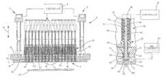
- FIG. 1is a cross-sectional view of a valve jet printer including a block diagram of a controller utilized to control the operation of said valve jet printer;
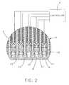
- FIG. 2is an enlarged view of detail A in FIG. 1 ;
- FIG. 3is an isolated view of one of the ink jets shown in FIG. 2 in a closed state
- FIG. 4is the ink jet of FIG. 3 in an open state
- FIG. 5is an isolated perspective view of the plunger rod of the ink jet shown in FIGS. 3 and 4 ;
- FIG. 6is a side view of the shank of the plunger rod shown in FIG. 5 including in phantom a cup-shaped cavity at one end thereof;
- FIG. 7is a cross-sectional view of the shank shown in FIG. 6 including a tip installed in the cup-shaped cavity.
- a valve jet printer 2includes a printer head assembly 4 that is coupled to one or more means for extending and retracting 6 , each of which is operative under the control of a controller 8 which operates under the control of a control program, to move the means for extending and retracting 6 in either the up or down direction shown by two-headed arrow 10 .
- Controller 8can be any suitable and/or desirable controller or computer that operates under the control of a software program in a manner known in the art to implement the present invention in the manner described hereinafter.
- Controller 8desirably includes a microprocessor, computer storage, e.g., RAM, ROM, EPROM, magnetic disk storage, and the like, and an input/output system.
- Controller 8can also include a media drive, such as a disk drive, CD-ROM drive, and the like, that can operate with a computer usable storage medium capable of storing all or part of the computer software which operates controller 8 . Further details regarding controller 8 are not described herein for the purpose of simplicity.
- the means for extending and retracting 6can be any suitable and/or desirable electrical, mechanical, and/or hydraulic system that is capable of moving printer head assembly 4 in the directions shown by two-headed arrow 10 for the purpose of dispensing ink on a substrate 70 . Further details regarding the means for extending and retracting 6 will not be described herein for the purpose of simplicity.
- printer head assembly 2includes a support frame 12 comprising an upper plate 14 and a lower plate 16 coupled together in the manner shown in FIG. 1 .
- Lower plate 16includes therein a cavity 18 formed in the surface of lower plate 16 that faces upper plate 14 when lower plate 16 and upper plate 14 are coupled together in the manner shown in FIG. 1 .
- a suitable seal or gasket 20is disposed between the lower surface of upper plate 14 and the upper surface of lower plate 16 at least around the periphery of cavity 18 to form therewith a fluid seal that avoids the leakage of fluid, such as ink, from cavity 18 during the use of valve jet printer 2 .
- cavity 18is desirably filled with suitable ink that is capable of being applied to a substrate (not shown) in a manner described hereinafter via one or more nozzles 22 of valve jet printer 2 .
- Inkcan be included in cavity 18 in any suitable and/or desirable manner.
- cavity 18receives ink from an ink reservoir 24 that is coupled in fluid communication with cavity 18 during operation of valve jet printer 2 .
- Valve jet printer 2includes a number of so-called “jets” 26 .
- Each jet 26includes a nozzle 22 , and a plunger rod 28 received in a sleeve 30 that is at least in part along the length of plunger rod 28 surrounded by a solenoid coil 32 which is spaced from sleeve 30 by an insulating sleeve 34 .
- insulating sleeve 34includes a wider base part 36 against which one end of solenoid coil 32 is positioned.
- a stop 38is positioned in sleeve 30 above plunger rod 28 .
- stop 38acts to limit the distance that plunger rod 28 moves away from nozzle 22 in operation.
- the overall travel length of plunger rod 28 in sleeve 30can be set as desired to allow a predetermined amount of ink to be dispensed through nozzle 22 each time jet 26 is activated.
- plunger rod 28includes an elongated shank 40 configured to be received within sleeve 30 in the manner shown in FIGS. 3 and 4 .
- Shank 40has a first end 42 that is configured to be positioned adjacent stop 38 when shank 40 is disposed within sleeve 30 .
- Shank 40also has a second end 44 that is disposed in cavity 18 in use.
- the second end 44 of shank 40has a larger diameter than the first end 42 of shank 40 and the body of shank 40 .
- Second end 44 of shank 40includes a tip 46 desirably formed of a perfluoroelastomer (FFKM) that is particularly suitable and desirable for the present application. Details regarding the perfluoroelastomer material forming tip 46 will be described hereinafter.
- FFKMperfluoroelastomer
- second end 44 of shank 40includes a cup-shaped cavity 48 having a convex bottom 50 and a circular side 52 that extends away from convex bottom 50 (to the right in FIG. 6 ).
- tip 46includes a concave base 54 that is complementary or substantially complementary to the shape of convex bottom 50 of second end 44 , whereupon when tip 46 is inserted into cavity 48 in the manner shown in FIG. 7 , the surfaces of convex bottom 50 and concave base 54 are substantially in contact.
- tip 46also includes an annular flange 56 disposed around concave base 54 .
- annular flange 56disposed around concave base 54 .
- circular side 52is rolled over and into contact with annular flange 56 thereby securing tip 46 into cavity 48 as shown in FIG. 7 .
- tip 46will have an exposed surface 58 that moves into and out of contact with nozzle 22 in use of plunger rod 28 in the manner described hereinafter.
- plunger rod 28is formed from a magnetically susceptible material or a material that has been processed to be magnetically susceptible.
- plunger rod 28is formed from stainless steel that has been annealed at a temperature between 788-843° C. for two hours then cooled at a rate of 56° C. per hour to 727° C. in order to make plunger rod 28 magnetically susceptible.
- plunger rod 28is annealed in the presence of dry hydrogen or a vacuum to prevent oxidation of plunger rod 28 during annealing. Because of the solvent(s) that are used with the ink of valve jet printer 2 , the use of stainless steel to form plunger rod 28 is desired to eliminate or avoid chemical attack of plunger rod 28 by said solvent(s).
- shank 40is slidably received in sleeve 30 with first end 42 positioned adjacent stop 38 and with second end 44 positioned in cavity 18 .
- a spring 60 surrounding shank 40 adjacent second end 44has a first end 62 resting against a shoulder 64 of second end 44 .
- a second end 66 of spring 60is secured in upper plate 14 in the manner shown in FIGS. 3 and 4 .
- Spring 60 and shoulder 64 of second end 44 of shank 40are arranged whereupon spring 60 biases surface 58 of tip 46 into contact with nozzle 22 , especially an orifice 68 of nozzle 22 through which ink is dispensed from cavity 18 in operation of valve jet printer 2 .
- each jet 26 and, more particularly, each plunger 28 of valve jet printer 2is controlled by controller 8 .
- controller 8when it is desired to maintain each jet 26 in its closed state, wherein no ink is being dispensed from said jet 26 , controller 8 withholds electrical power from the solenoid coil 32 associated with said jet 26 , whereupon spring 60 biases surface 58 of tip 46 into a sealing contact with orifice 68 of nozzle 22 .
- the urging of surface 58 into contact with orifice 68 as shown in FIG. 3prevents or avoids ink present in cavity 18 from passing into orifice 68 .
- controller 8causes electrical power to be supplied to solenoid coil 32 .
- solenoid coil 32produces in sleeve 30 a magnetic field that interacts magnetically with shank 40 , whereupon plunger rod 28 moves in a direction along its longitudinal axis from the position shown in FIG. 3 to the position shown in FIG. 4 whereupon surface 58 is spaced from orifice 68 thereby permitting ink present in cavity 18 to flow into orifice 68 .
- controller 8terminates the supply of electrical power to solenoid coil 32 thereby terminating the magnetic field that caused plunger rod 28 to move from the position shown in FIG. 3 to the position shown in FIG. 4 .
- spring 60 biased against shoulder 64 of second end 44 of shank 40urges second end 44 from the position shown in FIG. 4 back to the position shown in FIG. 3 , whereupon surface 58 once again is in contact and, desirably, seals orifice 68 from the entry of ink into orifice 68 from ink present in cavity 18 .
- controller 8controls the operation of each jet 26 in a manner to cause ink to be dispensed from printer head assembly 4 onto substrate 70 in a predetermined pattern determined by the programming of controller 8 .
- controller 8causes means for extending and retracting 6 to move printer head assembly into close proximity to substrate 70 during the dispensing of ink thereon and causes printer head assembly 4 to move away from substrate 70 after the desired pattern of ink has been dispensed thereon.
- tip 46is formed from a material that resumes its original shape after compression against nozzle 22 , and can withstand attack by the solvents used with the ink being dispensed by valve jet printer 2 .
- tip 46is formed from a perfluoroelastomer (FFKM) which is known to be a chemically inert perfluoroelastomer having a structure composed of carbon, fluorine, and oxygen atoms.
- FFKMperfluoroelastomer
- the perfluoroelastomer material forming tip 46is made from perfluoroalkylpolyether in the range of 5-8% and perfluoroelastomer less than 97%.
- This perfluoroelastomerexhibits outstanding high temperature properties and is the most chemically resistant elastomer available; effectively a rubber-like form of PTFE. It is superior to FKM elastomers, showing continuous dry-heat resistance to 260° C., with extended performance to 325° C. It is extremely inert chemically and shows excellent resistance to a majority of chemicals that attack other elastomers. Other notable properties include excellent resistance to oil-well sour gases, high temperature steam, low out gassing under vacuum, and good long-term high temperature compression set resistance.
- the desired form of perfluoroelastomer utilized to form tip 46has a Shore A hardness between 65 and 95, more desirably between 70 and 90 Shore A hardness; a tensile strength (lb/in 2 ) of approximately 2,000; a maximum continuous service temperature of 327° C.; and is flame resistant. It also has a 50% modulus of 15.5 MPa and a tensile strength at breaking of 22.75 MPa. It has an elongation at break of 75% and a compression set of 12% over 70 hours at 204° C., and 23% over 70 hours at 260° C. It also has a temperature of retraction, Tr10 5 at ⁇ 5° C., and a surface smoothness between 20-50 micro inches.
- the thickness of tip 46is desirably between 0.3 and 0.6 mm, and more desirably 0.5 mm.
- the present inventionis a valve jet printer 2 having a printer head assembly 4 that includes a number of jets 26 .
- the embodiment of printer head assembly 4 illustrated in FIG. 1includes a 1 ⁇ 16 linear array of jets 26 .
- printer head assembly 4can include any number and/or arrangement of jets 26 deemed suitable and/or desirable by one of ordinary skill in the art for a particular application.
- Each jet 26includes a plunger rod made of a material that is either magnetically susceptible or which can be treated to be magnetically susceptible, and which is resistant to attack by the solvent(s) included in the ink present in cavity 18 .
- Each plunger rod 28further includes a tip 46 made of a perfluoroelastomer that is also resistant to attack by the solvent(s) included in the ink present in cavity 18 .
Landscapes
- Ink Jet (AREA)
- Particle Formation And Scattering Control In Inkjet Printers (AREA)
- Magnetically Actuated Valves (AREA)
Abstract
Description
Claims (17)
Priority Applications (7)
| Application Number | Priority Date | Filing Date | Title |
|---|---|---|---|
| US13/282,522US8820871B2 (en) | 2010-10-27 | 2011-10-27 | Valve jet printer with inert plunger tip |
| US14/463,942US9108424B2 (en) | 2010-10-27 | 2014-08-20 | Valve jet printer with inert plunger tip |
| US14/827,682US9676184B2 (en) | 2010-10-27 | 2015-08-17 | Valve jet printer with inert plunger tip |
| US15/618,866US10059098B2 (en) | 2010-10-27 | 2017-06-09 | Valve jet printer with inert plunger tip |
| US16/113,263US10532569B2 (en) | 2010-10-27 | 2018-08-27 | Valve jet printer with inert plunger tip |
| US16/741,054US10864724B2 (en) | 2010-10-27 | 2020-01-13 | Valve jet printer with inert plunger tip |
| US17/120,998US11840080B2 (en) | 2010-10-27 | 2020-12-14 | Valve jet printer with inert plunger tip |
Applications Claiming Priority (2)
| Application Number | Priority Date | Filing Date | Title |
|---|---|---|---|
| US40708210P | 2010-10-27 | 2010-10-27 | |
| US13/282,522US8820871B2 (en) | 2010-10-27 | 2011-10-27 | Valve jet printer with inert plunger tip |
Related Child Applications (1)
| Application Number | Title | Priority Date | Filing Date |
|---|---|---|---|
| US14/463,942ContinuationUS9108424B2 (en) | 2010-10-27 | 2014-08-20 | Valve jet printer with inert plunger tip |
Publications (2)
| Publication Number | Publication Date |
|---|---|
| US20120105522A1 US20120105522A1 (en) | 2012-05-03 |
| US8820871B2true US8820871B2 (en) | 2014-09-02 |
Family
ID=45994738
Family Applications (7)
| Application Number | Title | Priority Date | Filing Date |
|---|---|---|---|
| US13/282,522Active2032-07-06US8820871B2 (en) | 2010-10-27 | 2011-10-27 | Valve jet printer with inert plunger tip |
| US14/463,942ActiveUS9108424B2 (en) | 2010-10-27 | 2014-08-20 | Valve jet printer with inert plunger tip |
| US14/827,682ActiveUS9676184B2 (en) | 2010-10-27 | 2015-08-17 | Valve jet printer with inert plunger tip |
| US15/618,866ActiveUS10059098B2 (en) | 2010-10-27 | 2017-06-09 | Valve jet printer with inert plunger tip |
| US16/113,263ActiveUS10532569B2 (en) | 2010-10-27 | 2018-08-27 | Valve jet printer with inert plunger tip |
| US16/741,054ActiveUS10864724B2 (en) | 2010-10-27 | 2020-01-13 | Valve jet printer with inert plunger tip |
| US17/120,998Active2032-10-27US11840080B2 (en) | 2010-10-27 | 2020-12-14 | Valve jet printer with inert plunger tip |
Family Applications After (6)
| Application Number | Title | Priority Date | Filing Date |
|---|---|---|---|
| US14/463,942ActiveUS9108424B2 (en) | 2010-10-27 | 2014-08-20 | Valve jet printer with inert plunger tip |
| US14/827,682ActiveUS9676184B2 (en) | 2010-10-27 | 2015-08-17 | Valve jet printer with inert plunger tip |
| US15/618,866ActiveUS10059098B2 (en) | 2010-10-27 | 2017-06-09 | Valve jet printer with inert plunger tip |
| US16/113,263ActiveUS10532569B2 (en) | 2010-10-27 | 2018-08-27 | Valve jet printer with inert plunger tip |
| US16/741,054ActiveUS10864724B2 (en) | 2010-10-27 | 2020-01-13 | Valve jet printer with inert plunger tip |
| US17/120,998Active2032-10-27US11840080B2 (en) | 2010-10-27 | 2020-12-14 | Valve jet printer with inert plunger tip |
Country Status (3)
| Country | Link |
|---|---|
| US (7) | US8820871B2 (en) |
| EP (2) | EP2632730B1 (en) |
| WO (1) | WO2012058373A2 (en) |
Cited By (3)
| Publication number | Priority date | Publication date | Assignee | Title |
|---|---|---|---|---|
| US20140354739A1 (en)* | 2010-10-27 | 2014-12-04 | Matthews Resources, Inc. | Valve jet printer with inert plunger tip |
| US10486418B2 (en) | 2015-07-08 | 2019-11-26 | System S.P.A. | Actuating device, particularly for ink-jet printheads, with electromagnetic isolation |
| US11648197B2 (en) | 2018-06-28 | 2023-05-16 | Arx, Llc | Dispensing method for producing dissolvable unit dose film constructs |
Families Citing this family (55)
| Publication number | Priority date | Publication date | Assignee | Title |
|---|---|---|---|---|
| ES2582727T3 (en) | 2013-09-12 | 2016-09-14 | Agfa Graphics Nv | Inkjet printing on a large, cuboid-shaped object |
| EP2883694A1 (en) | 2013-12-12 | 2015-06-17 | Agfa Graphics Nv | Laminated Safety Glass |
| WO2015110350A1 (en) | 2014-01-21 | 2015-07-30 | Agfa Graphics Nv | A conveyor belt for an inkjet print device |
| US10040291B2 (en)* | 2014-07-31 | 2018-08-07 | Hewlett-Packard Development Company, L.P. | Method and apparatus to reduce ink evaporation in printhead nozzles |
| EP3000602B1 (en) | 2014-09-26 | 2020-07-22 | Agfa Nv | High viscosity jetting method |
| ES2966849T3 (en) | 2014-10-31 | 2024-04-24 | Agfa Nv | Inkjet decorative laminate manufacturing procedures |
| EP3017957B1 (en) | 2014-11-04 | 2020-01-08 | Agfa Nv | A large inkjet flatbed table |
| EP3017960B1 (en) | 2014-11-05 | 2017-07-19 | Agfa Graphics Nv | Inkjet printing of pearlescent and metallic colours |
| EP3017943A1 (en) | 2014-11-06 | 2016-05-11 | Agfa Graphics Nv | A sustainable lithographic printing plate |
| EP3031610A1 (en) | 2014-12-08 | 2016-06-15 | Agfa Graphics Nv | A reliable calibration method for industrial inkjet systems |
| CN104476922A (en)* | 2014-12-10 | 2015-04-01 | 福州聚众鑫电子科技有限公司 | Spray nozzle structure of printing head of novel industrial printing machine |
| EP3034311B1 (en) | 2014-12-18 | 2017-10-11 | Agfa Graphics Nv | Inkjet printing of pearlescent and metallic colours |
| WO2016135545A1 (en)* | 2015-02-27 | 2016-09-01 | G.Tech S.R.L. | Printing device and machine for printing ceramic tiles or slabs |
| ITUB20151903A1 (en)* | 2015-07-08 | 2017-01-08 | System Spa | Actuator device, in particular for an ink jet printing head, with cooling system |
| EP3138691B1 (en) | 2015-09-02 | 2020-08-12 | Agfa Nv | Inkjet printing device with dimpled vacuum belt |
| EP3156241B1 (en) | 2015-10-12 | 2018-10-10 | Agfa Nv | A moving gantry flatbed table inkjet printer |
| ES2762630T3 (en) | 2015-10-23 | 2020-05-25 | Agfa Nv | Inkjet printing device for high grammage substrates |
| EP3159172B1 (en) | 2015-10-23 | 2020-07-29 | Agfa Nv | Inkjet printing device with removable flat substrate support device |
| USD797827S1 (en)* | 2016-02-11 | 2017-09-19 | Dover Europe Sàrl | Printing machine |
| USD798353S1 (en)* | 2016-02-11 | 2017-09-26 | Dover Europe Sàrl | Printing machine |
| DE102016014947A1 (en) | 2016-12-14 | 2018-06-14 | Dürr Systems Ag | Printhead for applying a coating agent |
| DE102016014946A1 (en) | 2016-12-14 | 2018-06-14 | Dürr Systems Ag | Printhead for applying a coating agent to a component |
| DE102016014944A1 (en) | 2016-12-14 | 2018-06-14 | Dürr Systems Ag | Coating method and corresponding coating device |
| DE102016014919A1 (en) | 2016-12-14 | 2018-06-14 | Dürr Systems Ag | Application device and method for applying a coating agent |
| DE102016014952A1 (en) | 2016-12-14 | 2018-06-14 | Dürr Systems Ag | Coating device for coating components |
| DE102016014956A1 (en) | 2016-12-14 | 2018-06-14 | Dürr Systems Ag | Coating device and associated operating method |
| DE102016014943A1 (en)* | 2016-12-14 | 2018-06-14 | Dürr Systems Ag | Printhead with tempering device |
| DE102016014951A1 (en) | 2016-12-14 | 2018-06-14 | Dürr Systems Ag | Coating device and associated operating method |
| DE102016014953A1 (en) | 2016-12-14 | 2018-06-14 | Dürr Systems Ag | Painting plant and corresponding painting process |
| DE102016014955A1 (en) | 2016-12-14 | 2018-06-14 | Dürr Systems Ag | Coating device and corresponding coating method |
| DE102016014920A1 (en) | 2016-12-14 | 2018-06-14 | Dürr Systems Ag | Printhead with sliding and / or rotating mechanism for at least one row of nozzles |
| DE102016014948A1 (en)* | 2016-12-14 | 2018-06-14 | Dürr Systems Ag | Printhead and related operating procedures |
| WO2018114303A1 (en) | 2016-12-22 | 2018-06-28 | Agfa Nv | Inkjet printer with vacuum system |
| JP2018103139A (en)* | 2016-12-28 | 2018-07-05 | セイコーエプソン株式会社 | Fluid discharge device |
| IT201700019466A1 (en)* | 2017-02-21 | 2018-08-21 | Tecno Italia S R L | DEVICE AND METHOD FOR THE DECORATION OF MANUFACTURED ARTICLES BY DIGITAL PRINTING |
| DE102017122495A1 (en) | 2017-09-27 | 2019-03-28 | Dürr Systems Ag | Applicator with a small nozzle spacing |
| DE102017122492A1 (en) | 2017-09-27 | 2019-03-28 | Dürr Systems Ag | Applicator with an integrated control circuit |
| DE102017122488A1 (en) | 2017-09-27 | 2019-03-28 | Dürr Systems Ag | Applicator with a sealing membrane |
| DE102017122493A1 (en) | 2017-09-27 | 2019-03-28 | Dürr Systems Ag | Applicator with small nozzle spacing |
| EP3599094B1 (en)* | 2018-07-24 | 2024-05-08 | Dover Europe Sàrl | Visual verification system and method |
| JP7310404B2 (en)* | 2018-08-01 | 2023-07-19 | 株式会社リコー | Liquid ejection head, head unit, device for ejecting liquid, and liquid ejection method |
| US10987927B2 (en)* | 2018-08-01 | 2021-04-27 | Ricoh Company, Ltd. | Liquid discharge head, head unit, apparatus for discharging liquid, and liquid discharging method |
| JP7489092B2 (en)* | 2020-04-10 | 2024-05-23 | 兵神装備株式会社 | Liquid application device |
| JP7553316B2 (en) | 2020-10-14 | 2024-09-18 | トヨタ自動車東日本株式会社 | Paint injection nozzle |
| JP7553315B2 (en)* | 2020-10-14 | 2024-09-18 | トヨタ自動車東日本株式会社 | Paint injection nozzle and control method thereof |
| CN117377573A (en)* | 2021-06-08 | 2024-01-09 | 株式会社理光 | Liquid discharge head and liquid discharge apparatus |
| IT202100015269A1 (en)* | 2021-06-10 | 2022-12-10 | Soremartec Sa | SYSTEM FOR DEPOSITING FOOD MATERIAL IN THE FLUID STATE ON A FOOD PRODUCT |
| JP2023097887A (en)* | 2021-12-28 | 2023-07-10 | 株式会社リコー | Liquid droplet discharge module, liquid droplet discharge head, and liquid droplet discharge device |
| JP2023097889A (en) | 2021-12-28 | 2023-07-10 | 株式会社リコー | liquid ejection head, liquid ejection device |
| JP2023127822A (en) | 2022-03-02 | 2023-09-14 | 株式会社リコー | Liquid discharge head, head unit and liquid discharge device |
| US12358299B2 (en)* | 2022-03-15 | 2025-07-15 | Ricoh Company, Ltd. | Liquid discharge head and liquid discharge apparatus |
| WO2023222591A1 (en) | 2022-05-16 | 2023-11-23 | Agfa Nv | Manufacturing a decorated leather article |
| JP2023173184A (en)* | 2022-05-25 | 2023-12-07 | 株式会社リコー | Liquid discharge head, head module, and liquid discharge device |
| EP4289975A1 (en) | 2022-06-08 | 2023-12-13 | Agfa Nv | Decorating a hide by inkjet technology |
| KR102753079B1 (en)* | 2023-01-13 | 2025-01-14 | 이승구 | Marking Head System |
Citations (29)
| Publication number | Priority date | Publication date | Assignee | Title |
|---|---|---|---|---|
| US4420945A (en) | 1982-10-25 | 1983-12-20 | Centrifugal Piston Expander, Inc. | Method and apparatus for extracting energy from a pressured gas |
| US4433551A (en) | 1982-10-25 | 1984-02-28 | Centrifugal Piston Expander, Inc. | Method and apparatus for deriving mechanical energy from a heat source |
| US4449379A (en) | 1982-10-25 | 1984-05-22 | Centrifugal Piston Expander Inc. | Method and apparatus for extracting heat and mechanical energy from a pressured gas |
| US4513575A (en) | 1982-10-25 | 1985-04-30 | Centrifugal Piston Expander, Inc. | Centrifugal piston expander |
| US4513576A (en) | 1983-12-12 | 1985-04-30 | Centrifugal Piston Expander, Inc. | Gas pressure operated power source |
| US4520632A (en) | 1982-10-25 | 1985-06-04 | Centrifugal Piston Expander, Inc. | Method and apparatus for extracting heat and mechanical energy from a pressured gas |
| US4734190A (en) | 1987-04-17 | 1988-03-29 | W. R. Grace & Co. | Sample dispensing system for liquid chromatography |
| US4793379A (en) | 1982-07-16 | 1988-12-27 | Eidsmore Paul G | Supply cylinder shut-off and flow control valve |
| US4875058A (en)* | 1986-12-12 | 1989-10-17 | Markpoint System Ab | Valve device for a matrix printer |
| EP0371763A2 (en) | 1988-12-01 | 1990-06-06 | Willett International Limited | Method for operating a valve |
| US5533868A (en) | 1995-02-24 | 1996-07-09 | Battelle Memorial Institute | Apparatus and method for batch-wire continuous pumping |
| JPH08230203A (en) | 1995-02-27 | 1996-09-10 | Kishu Giken Kogyo Kk | Prevention of operation inferiority of ink jet head |
| US6540340B2 (en) | 1998-10-21 | 2003-04-01 | Timothy R. Thorpe | Ink supply system |
| US20050231553A1 (en) | 2002-02-14 | 2005-10-20 | Horsnell David A | Solenoid valve |
| US7014636B2 (en) | 2002-11-21 | 2006-03-21 | Alza Corporation | Osmotic delivery device having a two-way valve and a dynamically self-adjusting flow channel |
| US7070255B2 (en) | 2002-12-13 | 2006-07-04 | Konica Minolta Holdings, Inc. | Capping member, cleaning member, piping member, ink tank member, and UV curable ink jet recording apparatus fitted with the above members |
| US20060201613A1 (en) | 2005-03-10 | 2006-09-14 | Norihisa Minowa | Bonding perfluoroelastomers to aluminum |
| US7163688B2 (en) | 2001-06-22 | 2007-01-16 | Alza Corporation | Osmotic implant with membrane and membrane retention means |
| US7231766B2 (en) | 2005-08-19 | 2007-06-19 | Hall David R | High pressure intensifying piston valve |
| US7387365B2 (en) | 1997-07-15 | 2008-06-17 | Silverbrook Research Pty Ltd | Nozzle for an inkjet printer incorporating a plunger assembly |
| US7407241B2 (en) | 2004-08-30 | 2008-08-05 | Sharp Kabushiki Kaisha | Ink-jet head device, ink-jet device, and ink-supplying method of ink-jet head device |
| US7410245B2 (en) | 2001-10-13 | 2008-08-12 | Willett International Limited | Solenoid valve |
| EP1990194A2 (en) | 2007-05-08 | 2008-11-12 | Expert s.r.l. | Fluid control device |
| US20090079792A1 (en) | 2007-09-25 | 2009-03-26 | Kabushiki Kaisha Toshiba | Droplet jetting head |
| US20090118711A1 (en)* | 2001-09-07 | 2009-05-07 | Medtronic, Inc. | Reduced-noise implantable infusion device |
| US20090202608A1 (en) | 2008-02-13 | 2009-08-13 | Alessi Thomas R | Devices, formulations, and methods for delivery of multiple beneficial agents |
| US7628468B2 (en) | 1997-07-15 | 2009-12-08 | Silverbrook Research Pty Ltd | Nozzle with reciprocating plunger |
| US7682356B2 (en) | 2006-08-09 | 2010-03-23 | Intarcia Therapeutics, Inc. | Osmotic delivery systems and piston assemblies for use therein |
| US7731336B2 (en) | 1997-07-15 | 2010-06-08 | Silverbrook Research Pty Ltd | Inkjet nozzle arrangement |
Family Cites Families (7)
| Publication number | Priority date | Publication date | Assignee | Title |
|---|---|---|---|---|
| US59098A (en)* | 1866-10-23 | Improved mode of hanging bells | ||
| US5819799A (en)* | 1996-05-10 | 1998-10-13 | The Lee Company | Method and apparatus for rapid fluid dispensing |
| SE0202247D0 (en)* | 2002-07-18 | 2002-07-18 | Mydata Automation Ab | Jetting device and method at a jetting device |
| US20050001869A1 (en)* | 2003-05-23 | 2005-01-06 | Nordson Corporation | Viscous material noncontact jetting system |
| JP4695870B2 (en)* | 2004-05-13 | 2011-06-08 | ノイベルク有限会社 | Diaphragm pump and electronic component manufacturing equipment |
| JP2009154123A (en)* | 2007-12-27 | 2009-07-16 | Riso Kagaku Corp | High viscosity fluid discharge apparatus and high viscosity fluid discharge method |
| US8820871B2 (en)* | 2010-10-27 | 2014-09-02 | Matthews Resources, Inc. | Valve jet printer with inert plunger tip |
- 2011
- 2011-10-27USUS13/282,522patent/US8820871B2/enactiveActive
- 2011-10-27WOPCT/US2011/057996patent/WO2012058373A2/enactiveApplication Filing
- 2011-10-27EPEP11837056.8Apatent/EP2632730B1/enactiveActive
- 2011-10-27EPEP19189298.3Apatent/EP3587121B1/enactiveActive
- 2014
- 2014-08-20USUS14/463,942patent/US9108424B2/enactiveActive
- 2015
- 2015-08-17USUS14/827,682patent/US9676184B2/enactiveActive
- 2017
- 2017-06-09USUS15/618,866patent/US10059098B2/enactiveActive
- 2018
- 2018-08-27USUS16/113,263patent/US10532569B2/enactiveActive
- 2020
- 2020-01-13USUS16/741,054patent/US10864724B2/enactiveActive
- 2020-12-14USUS17/120,998patent/US11840080B2/enactiveActive
Patent Citations (31)
| Publication number | Priority date | Publication date | Assignee | Title |
|---|---|---|---|---|
| US4793379A (en) | 1982-07-16 | 1988-12-27 | Eidsmore Paul G | Supply cylinder shut-off and flow control valve |
| US4420945A (en) | 1982-10-25 | 1983-12-20 | Centrifugal Piston Expander, Inc. | Method and apparatus for extracting energy from a pressured gas |
| US4433551A (en) | 1982-10-25 | 1984-02-28 | Centrifugal Piston Expander, Inc. | Method and apparatus for deriving mechanical energy from a heat source |
| US4449379A (en) | 1982-10-25 | 1984-05-22 | Centrifugal Piston Expander Inc. | Method and apparatus for extracting heat and mechanical energy from a pressured gas |
| US4513575A (en) | 1982-10-25 | 1985-04-30 | Centrifugal Piston Expander, Inc. | Centrifugal piston expander |
| US4520632A (en) | 1982-10-25 | 1985-06-04 | Centrifugal Piston Expander, Inc. | Method and apparatus for extracting heat and mechanical energy from a pressured gas |
| US4513576A (en) | 1983-12-12 | 1985-04-30 | Centrifugal Piston Expander, Inc. | Gas pressure operated power source |
| US4875058A (en)* | 1986-12-12 | 1989-10-17 | Markpoint System Ab | Valve device for a matrix printer |
| US4734190A (en) | 1987-04-17 | 1988-03-29 | W. R. Grace & Co. | Sample dispensing system for liquid chromatography |
| EP0371763A2 (en) | 1988-12-01 | 1990-06-06 | Willett International Limited | Method for operating a valve |
| US5533868A (en) | 1995-02-24 | 1996-07-09 | Battelle Memorial Institute | Apparatus and method for batch-wire continuous pumping |
| JPH08230203A (en) | 1995-02-27 | 1996-09-10 | Kishu Giken Kogyo Kk | Prevention of operation inferiority of ink jet head |
| US7387365B2 (en) | 1997-07-15 | 2008-06-17 | Silverbrook Research Pty Ltd | Nozzle for an inkjet printer incorporating a plunger assembly |
| US7731336B2 (en) | 1997-07-15 | 2010-06-08 | Silverbrook Research Pty Ltd | Inkjet nozzle arrangement |
| US7628468B2 (en) | 1997-07-15 | 2009-12-08 | Silverbrook Research Pty Ltd | Nozzle with reciprocating plunger |
| US6540340B2 (en) | 1998-10-21 | 2003-04-01 | Timothy R. Thorpe | Ink supply system |
| US7163688B2 (en) | 2001-06-22 | 2007-01-16 | Alza Corporation | Osmotic implant with membrane and membrane retention means |
| US20090118711A1 (en)* | 2001-09-07 | 2009-05-07 | Medtronic, Inc. | Reduced-noise implantable infusion device |
| US7410245B2 (en) | 2001-10-13 | 2008-08-12 | Willett International Limited | Solenoid valve |
| US20050231553A1 (en) | 2002-02-14 | 2005-10-20 | Horsnell David A | Solenoid valve |
| US7316680B2 (en) | 2002-11-21 | 2008-01-08 | Intarcia Therapeutics, Inc. | Osmotic delivery device having a two-way valve and a dynamically self-adjusting flow channel |
| US7014636B2 (en) | 2002-11-21 | 2006-03-21 | Alza Corporation | Osmotic delivery device having a two-way valve and a dynamically self-adjusting flow channel |
| US7232205B2 (en) | 2002-12-13 | 2007-06-19 | Konica Minolta Holdings, Inc. | Capping member, cleaning member, piping member, ink tank member, and UV curable ink jet recording apparatus fitted with the above members |
| US7070255B2 (en) | 2002-12-13 | 2006-07-04 | Konica Minolta Holdings, Inc. | Capping member, cleaning member, piping member, ink tank member, and UV curable ink jet recording apparatus fitted with the above members |
| US7407241B2 (en) | 2004-08-30 | 2008-08-05 | Sharp Kabushiki Kaisha | Ink-jet head device, ink-jet device, and ink-supplying method of ink-jet head device |
| US20060201613A1 (en) | 2005-03-10 | 2006-09-14 | Norihisa Minowa | Bonding perfluoroelastomers to aluminum |
| US7231766B2 (en) | 2005-08-19 | 2007-06-19 | Hall David R | High pressure intensifying piston valve |
| US7682356B2 (en) | 2006-08-09 | 2010-03-23 | Intarcia Therapeutics, Inc. | Osmotic delivery systems and piston assemblies for use therein |
| EP1990194A2 (en) | 2007-05-08 | 2008-11-12 | Expert s.r.l. | Fluid control device |
| US20090079792A1 (en) | 2007-09-25 | 2009-03-26 | Kabushiki Kaisha Toshiba | Droplet jetting head |
| US20090202608A1 (en) | 2008-02-13 | 2009-08-13 | Alessi Thomas R | Devices, formulations, and methods for delivery of multiple beneficial agents |
Non-Patent Citations (9)
| Title |
|---|
| European Search Report and Written Opinion dated Jun. 1, 2012 for EP2632730. |
| International Search Report dated Jun. 1, 2012 for PCT/US2011/057996 (2 pages). |
| Introducing Kalrez® Spectrum(TM) 7090: The latest product for high durometer/low compression set, and rapid gas decompression resistance, Dupont Performance Elastomers, Jan. 2009, 2 pages. |
| Introducing Kalrez® Spectrum™ 7090: The latest product for high durometer/low compression set, and rapid gas decompression resistance, Dupont Performance Elastomers, Jan. 2009, 2 pages. |
| Kalrez Fluoroelastomer Semifinished Parts and Shapes in Synonym List KRZ042, Material Safety Data Sheet, Feb. 15, 2007, 15 pages. |
| Kalrez perfluoroelastomer semi-finished parts and shapes, Material Safety Data Sheet, Feb. 2, 2009, http://msds.dupont.com/msds/pdfs/EN/PEN-09004a358045cac9.pdf, 6 pages. |
| Kalrez perfluoroelastomer semi-finished parts and shapes, Material Safety Data Sheet, Feb. 2, 2009, http://msds.dupont.com/msds/pdfs/EN/PEN—09004a358045cac9.pdf, 6 pages. |
| Kalrez® Spectrum(TM) 7090 Technical Information, Brochure, Jun. 2007, 2 pages. |
| Kalrez® Spectrum™ 7090 Technical Information, Brochure, Jun. 2007, 2 pages. |
Cited By (12)
| Publication number | Priority date | Publication date | Assignee | Title |
|---|---|---|---|---|
| US20140354739A1 (en)* | 2010-10-27 | 2014-12-04 | Matthews Resources, Inc. | Valve jet printer with inert plunger tip |
| US9108424B2 (en)* | 2010-10-27 | 2015-08-18 | Matthews Resources, Inc. | Valve jet printer with inert plunger tip |
| US20160185111A1 (en)* | 2010-10-27 | 2016-06-30 | Matthews Resources, Inc. | Valve jet printer with inert plunger tip |
| US9676184B2 (en)* | 2010-10-27 | 2017-06-13 | Matthews Resources, Inc. | Valve jet printer with inert plunger tip |
| US10059098B2 (en)* | 2010-10-27 | 2018-08-28 | Matthews International Corporation | Valve jet printer with inert plunger tip |
| US20190092006A1 (en)* | 2010-10-27 | 2019-03-28 | Matthews International Corporation | Valve jet printer with inert plunger tip |
| US10532569B2 (en)* | 2010-10-27 | 2020-01-14 | Matthews International Corporation | Valve jet printer with inert plunger tip |
| US10864724B2 (en) | 2010-10-27 | 2020-12-15 | Matthews International Corporation | Valve jet printer with inert plunger tip |
| US11840080B2 (en) | 2010-10-27 | 2023-12-12 | Matthews International Corporation | Valve jet printer with inert plunger tip |
| US10486418B2 (en) | 2015-07-08 | 2019-11-26 | System S.P.A. | Actuating device, particularly for ink-jet printheads, with electromagnetic isolation |
| US11648197B2 (en) | 2018-06-28 | 2023-05-16 | Arx, Llc | Dispensing method for producing dissolvable unit dose film constructs |
| US12268775B2 (en) | 2018-06-28 | 2025-04-08 | Arx, Llc | Dispensing method for producing dissolvable unit dose film constructs |
Also Published As
| Publication number | Publication date |
|---|---|
| US20160185111A1 (en) | 2016-06-30 |
| US20210206166A1 (en) | 2021-07-08 |
| EP2632730A4 (en) | 2018-03-28 |
| US9676184B2 (en) | 2017-06-13 |
| US10864724B2 (en) | 2020-12-15 |
| US20120105522A1 (en) | 2012-05-03 |
| EP2632730B1 (en) | 2019-08-07 |
| US20140354739A1 (en) | 2014-12-04 |
| US11840080B2 (en) | 2023-12-12 |
| US20180086060A1 (en) | 2018-03-29 |
| US20200215818A1 (en) | 2020-07-09 |
| EP3587121B1 (en) | 2021-04-07 |
| WO2012058373A2 (en) | 2012-05-03 |
| EP3587121A1 (en) | 2020-01-01 |
| US10532569B2 (en) | 2020-01-14 |
| EP2632730A2 (en) | 2013-09-04 |
| US10059098B2 (en) | 2018-08-28 |
| WO2012058373A3 (en) | 2012-07-26 |
| US20190092006A1 (en) | 2019-03-28 |
| US9108424B2 (en) | 2015-08-18 |
Similar Documents
| Publication | Publication Date | Title |
|---|---|---|
| US11840080B2 (en) | Valve jet printer with inert plunger tip | |
| KR100889577B1 (en) | Diaphragm valve | |
| JPH02117836A (en) | Liquid pass switch for printer | |
| KR20180087593A (en) | Solenoid valve including pilot plunger head which is moving independently from the pilot plunger | |
| KR20010101061A (en) | Valve for controlling liquids | |
| US20200332916A1 (en) | Metering device and method for metering liquid media | |
| KR20200060714A (en) | Applicators with short nozzle spacing | |
| JP7197108B2 (en) | injector | |
| JP2008215209A (en) | Fuel injection valve | |
| US7311273B2 (en) | Fluid injection device | |
| JP6668693B2 (en) | Pressure adjusting device and liquid ejecting device | |
| WO2010053020A1 (en) | Control valve structure of accumulator fuel injection equipment | |
| KR102783139B1 (en) | Method of manufacturing gaskets | |
| JP2020532695A (en) | Metering device for controlling gaseous media | |
| KR100893101B1 (en) | Solenoid valve coupling structure of industrial print head | |
| NL1037570C2 (en) | A device for dispensing a substance. | |
| JP7298184B2 (en) | injector | |
| HK40017630A (en) | Ejector | |
| JP5506628B2 (en) | Pressure regulator, discharge unit, discharge device | |
| EP3411589A1 (en) | Fuel injector nozzle and needle arrangement | |
| KR19990075463A (en) | Gas flow direction control valve of combustion device |
Legal Events
| Date | Code | Title | Description |
|---|---|---|---|
| AS | Assignment | Owner name:MATTHEWS RESOURCES, INC., DELAWARE Free format text:ASSIGNMENT OF ASSIGNORS INTEREST;ASSIGNORS:WALLSTEN, HANS ELON;KACK, NILS JOHAN FREDRIK;REEL/FRAME:027469/0389 Effective date:20111208 | |
| STCF | Information on status: patent grant | Free format text:PATENTED CASE | |
| AS | Assignment | Owner name:MATTHEWS INTERNATIONAL CORPORATION, PENNSYLVANIA Free format text:ASSIGNMENT OF ASSIGNORS INTEREST;ASSIGNOR:MATTHEWS RESOURCES, INC.;REEL/FRAME:044707/0952 Effective date:20170929 | |
| MAFP | Maintenance fee payment | Free format text:PAYMENT OF MAINTENANCE FEE, 4TH YEAR, LARGE ENTITY (ORIGINAL EVENT CODE: M1551) Year of fee payment:4 | |
| MAFP | Maintenance fee payment | Free format text:PAYMENT OF MAINTENANCE FEE, 8TH YEAR, LARGE ENTITY (ORIGINAL EVENT CODE: M1552); ENTITY STATUS OF PATENT OWNER: LARGE ENTITY Year of fee payment:8 | |
| AS | Assignment | Owner name:TRUIST BANK, NORTH CAROLINA Free format text:SECURITY INTEREST;ASSIGNOR:MATTHEWS INTERNATIONAL CORPORATION;REEL/FRAME:069379/0573 Effective date:20241112 Owner name:CITIZENS BANK, N.A., PENNSYLVANIA Free format text:SECURITY INTEREST;ASSIGNOR:MATTHEWS INTERNATIONAL CORPORATION;REEL/FRAME:069379/0528 Effective date:20241112 |