US8820293B1 - Injector-igniter with thermochemical regeneration - Google Patents
Injector-igniter with thermochemical regenerationDownload PDFInfo
- Publication number
- US8820293B1 US8820293B1US13/841,548US201313841548AUS8820293B1US 8820293 B1US8820293 B1US 8820293B1US 201313841548 AUS201313841548 AUS 201313841548AUS 8820293 B1US8820293 B1US 8820293B1
- Authority
- US
- United States
- Prior art keywords
- injector
- actuator
- valve
- igniter
- injector housing
- Prior art date
- Legal status (The legal status is an assumption and is not a legal conclusion. Google has not performed a legal analysis and makes no representation as to the accuracy of the status listed.)
- Expired - Fee Related
Links
- 230000008929regenerationEffects0.000title1
- 238000011069regeneration methodMethods0.000title1
- 239000000446fuelSubstances0.000claimsabstractdescription83
- 238000002347injectionMethods0.000claimsabstractdescription42
- 239000007924injectionSubstances0.000claimsabstractdescription42
- 239000012530fluidSubstances0.000claimsabstractdescription34
- 238000004891communicationMethods0.000claimsabstractdescription21
- 239000002828fuel tankSubstances0.000claimsabstractdescription8
- 239000004020conductorSubstances0.000claimsdescription45
- 239000012212insulatorSubstances0.000claimsdescription22
- 239000000919ceramicSubstances0.000claimsdescription8
- 229910010293ceramic materialInorganic materials0.000claimsdescription5
- 239000001257hydrogenSubstances0.000abstractdescription16
- 229910052739hydrogenInorganic materials0.000abstractdescription16
- UFHFLCQGNIYNRP-UHFFFAOYSA-NHydrogenChemical compound[H][H]UFHFLCQGNIYNRP-UHFFFAOYSA-N0.000abstractdescription15
- 238000002485combustion reactionMethods0.000abstractdescription15
- 230000000153supplemental effectEffects0.000abstractdescription3
- 238000005516engineering processMethods0.000description22
- 150000002500ionsChemical class0.000description9
- VNWKTOKETHGBQD-UHFFFAOYSA-NmethaneChemical compoundCVNWKTOKETHGBQD-UHFFFAOYSA-N0.000description8
- 239000000126substanceSubstances0.000description8
- 230000005611electricityEffects0.000description7
- 239000011521glassSubstances0.000description6
- 239000006096absorbing agentSubstances0.000description5
- 238000004519manufacturing processMethods0.000description5
- 230000035939shockEffects0.000description5
- 230000006835compressionEffects0.000description4
- 238000007906compressionMethods0.000description4
- 238000000034methodMethods0.000description4
- 238000003860storageMethods0.000description4
- 230000003321amplificationEffects0.000description3
- 239000007789gasSubstances0.000description3
- 239000000852hydrogen donorSubstances0.000description3
- 230000001939inductive effectEffects0.000description3
- 238000003199nucleic acid amplification methodMethods0.000description3
- 238000005381potential energyMethods0.000description3
- 230000000717retained effectEffects0.000description3
- 238000012384transportation and deliveryMethods0.000description3
- QGZKDVFQNNGYKY-UHFFFAOYSA-NAmmoniaChemical compoundNQGZKDVFQNNGYKY-UHFFFAOYSA-N0.000description2
- IJGRMHOSHXDMSA-UHFFFAOYSA-NAtomic nitrogenChemical compoundN#NIJGRMHOSHXDMSA-UHFFFAOYSA-N0.000description2
- CURLTUGMZLYLDI-UHFFFAOYSA-NCarbon dioxideChemical compoundO=C=OCURLTUGMZLYLDI-UHFFFAOYSA-N0.000description2
- ATUOYWHBWRKTHZ-UHFFFAOYSA-NPropaneChemical compoundCCCATUOYWHBWRKTHZ-UHFFFAOYSA-N0.000description2
- 230000001133accelerationEffects0.000description2
- 239000003990capacitorSubstances0.000description2
- 239000002131composite materialSubstances0.000description2
- 238000006073displacement reactionMethods0.000description2
- 230000000694effectsEffects0.000description2
- 238000010438heat treatmentMethods0.000description2
- 230000000977initiatory effectEffects0.000description2
- BDAGIHXWWSANSR-UHFFFAOYSA-Nmethanoic acidNatural productsOC=OBDAGIHXWWSANSR-UHFFFAOYSA-N0.000description2
- 239000000203mixtureSubstances0.000description2
- 239000003345natural gasSubstances0.000description2
- 239000007800oxidant agentSubstances0.000description2
- 230000001590oxidative effectEffects0.000description2
- 229920001721polyimidePolymers0.000description2
- 230000001172regenerating effectEffects0.000description2
- 230000004044responseEffects0.000description2
- XLYOFNOQVPJJNP-UHFFFAOYSA-NwaterSubstancesOXLYOFNOQVPJJNP-UHFFFAOYSA-N0.000description2
- OSWFIVFLDKOXQC-UHFFFAOYSA-N4-(3-methoxyphenyl)anilineChemical compoundCOC1=CC=CC(C=2C=CC(N)=CC=2)=C1OSWFIVFLDKOXQC-UHFFFAOYSA-N0.000description1
- PNEYBMLMFCGWSK-UHFFFAOYSA-NAluminaChemical compound[O-2].[O-2].[O-2].[Al+3].[Al+3]PNEYBMLMFCGWSK-UHFFFAOYSA-N0.000description1
- CIWBSHSKHKDKBQ-JLAZNSOCSA-NAscorbic acidChemical compoundOC[C@H](O)[C@H]1OC(=O)C(O)=C1OCIWBSHSKHKDKBQ-JLAZNSOCSA-N0.000description1
- UGFAIRIUMAVXCW-UHFFFAOYSA-NCarbon monoxideChemical compound[O+]#[C-]UGFAIRIUMAVXCW-UHFFFAOYSA-N0.000description1
- OTMSDBZUPAUEDD-UHFFFAOYSA-NEthaneChemical compoundCCOTMSDBZUPAUEDD-UHFFFAOYSA-N0.000description1
- LFQSCWFLJHTTHZ-UHFFFAOYSA-NEthanolChemical compoundCCOLFQSCWFLJHTTHZ-UHFFFAOYSA-N0.000description1
- 239000004642PolyimideSubstances0.000description1
- 229920006362Teflon®Polymers0.000description1
- XSQUKJJJFZCRTK-UHFFFAOYSA-NUreaChemical compoundNC(N)=OXSQUKJJJFZCRTK-UHFFFAOYSA-N0.000description1
- 150000001298alcoholsChemical class0.000description1
- 229910021529ammoniaInorganic materials0.000description1
- 238000013459approachMethods0.000description1
- QVGXLLKOCUKJST-UHFFFAOYSA-Natomic oxygenChemical compound[O]QVGXLLKOCUKJST-UHFFFAOYSA-N0.000description1
- 230000005540biological transmissionEffects0.000description1
- 239000001273butaneSubstances0.000description1
- 239000004202carbamideSubstances0.000description1
- 239000001569carbon dioxideSubstances0.000description1
- 229910002092carbon dioxideInorganic materials0.000description1
- 229910002091carbon monoxideInorganic materials0.000description1
- 230000001413cellular effectEffects0.000description1
- 239000003795chemical substances by applicationSubstances0.000description1
- 230000001143conditioned effectEffects0.000description1
- 238000010276constructionMethods0.000description1
- 238000001816coolingMethods0.000description1
- 230000008878couplingEffects0.000description1
- 238000010168coupling processMethods0.000description1
- 238000005859coupling reactionMethods0.000description1
- 238000013461designMethods0.000description1
- 238000011161developmentMethods0.000description1
- 239000002283diesel fuelSubstances0.000description1
- 238000004146energy storageMethods0.000description1
- 239000000835fiberSubstances0.000description1
- 235000019253formic acidNutrition0.000description1
- 230000006870functionEffects0.000description1
- 239000006112glass ceramic compositionSubstances0.000description1
- 239000013003healing agentSubstances0.000description1
- 229930195733hydrocarbonNatural products0.000description1
- 150000002430hydrocarbonsChemical class0.000description1
- 150000002431hydrogenChemical class0.000description1
- 239000011810insulating materialSubstances0.000description1
- 238000009413insulationMethods0.000description1
- 230000005865ionizing radiationEffects0.000description1
- 230000007246mechanismEffects0.000description1
- 230000005055memory storageEffects0.000description1
- 239000010445micaSubstances0.000description1
- 229910052618mica groupInorganic materials0.000description1
- 238000012986modificationMethods0.000description1
- 230000004048modificationEffects0.000description1
- 239000000178monomerSubstances0.000description1
- IJDNQMDRQITEOD-UHFFFAOYSA-Nn-butaneChemical compoundCCCCIJDNQMDRQITEOD-UHFFFAOYSA-N0.000description1
- OFBQJSOFQDEBGM-UHFFFAOYSA-Nn-pentaneNatural productsCCCCCOFBQJSOFQDEBGM-UHFFFAOYSA-N0.000description1
- 229910052757nitrogenInorganic materials0.000description1
- 238000005457optimizationMethods0.000description1
- 239000001301oxygenSubstances0.000description1
- 229910052760oxygenInorganic materials0.000description1
- 238000004806packaging method and processMethods0.000description1
- 230000037361pathwayEffects0.000description1
- 230000035515penetrationEffects0.000description1
- 239000003209petroleum derivativeSubstances0.000description1
- 229920000642polymerPolymers0.000description1
- 239000002243precursorSubstances0.000description1
- 238000012545processingMethods0.000description1
- 239000001294propaneSubstances0.000description1
- 230000008439repair processEffects0.000description1
- 238000007789sealingMethods0.000description1
- 239000007787solidSubstances0.000description1
- 239000000725suspensionSubstances0.000description1
- 239000002966varnishSubstances0.000description1
- 238000004804windingMethods0.000description1
Images


Classifications
- F—MECHANICAL ENGINEERING; LIGHTING; HEATING; WEAPONS; BLASTING
- F02—COMBUSTION ENGINES; HOT-GAS OR COMBUSTION-PRODUCT ENGINE PLANTS
- F02M—SUPPLYING COMBUSTION ENGINES IN GENERAL WITH COMBUSTIBLE MIXTURES OR CONSTITUENTS THEREOF
- F02M57/00—Fuel-injectors combined or associated with other devices
- F02M57/06—Fuel-injectors combined or associated with other devices the devices being sparking plugs
- F—MECHANICAL ENGINEERING; LIGHTING; HEATING; WEAPONS; BLASTING
- F02—COMBUSTION ENGINES; HOT-GAS OR COMBUSTION-PRODUCT ENGINE PLANTS
- F02M—SUPPLYING COMBUSTION ENGINES IN GENERAL WITH COMBUSTIBLE MIXTURES OR CONSTITUENTS THEREOF
- F02M51/00—Fuel-injection apparatus characterised by being operated electrically
- F02M51/06—Injectors peculiar thereto with means directly operating the valve needle
- F02M51/0603—Injectors peculiar thereto with means directly operating the valve needle using piezoelectric or magnetostrictive operating means
- F—MECHANICAL ENGINEERING; LIGHTING; HEATING; WEAPONS; BLASTING
- F02—COMBUSTION ENGINES; HOT-GAS OR COMBUSTION-PRODUCT ENGINE PLANTS
- F02B—INTERNAL-COMBUSTION PISTON ENGINES; COMBUSTION ENGINES IN GENERAL
- F02B43/00—Engines characterised by operating on gaseous fuels; Plants including such engines
- F02B43/10—Engines or plants characterised by use of other specific gases, e.g. acetylene, oxyhydrogen
- F—MECHANICAL ENGINEERING; LIGHTING; HEATING; WEAPONS; BLASTING
- F02—COMBUSTION ENGINES; HOT-GAS OR COMBUSTION-PRODUCT ENGINE PLANTS
- F02P—IGNITION, OTHER THAN COMPRESSION IGNITION, FOR INTERNAL-COMBUSTION ENGINES; TESTING OF IGNITION TIMING IN COMPRESSION-IGNITION ENGINES
- F02P13/00—Sparking plugs structurally combined with other parts of internal-combustion engines
- F—MECHANICAL ENGINEERING; LIGHTING; HEATING; WEAPONS; BLASTING
- F02—COMBUSTION ENGINES; HOT-GAS OR COMBUSTION-PRODUCT ENGINE PLANTS
- F02P—IGNITION, OTHER THAN COMPRESSION IGNITION, FOR INTERNAL-COMBUSTION ENGINES; TESTING OF IGNITION TIMING IN COMPRESSION-IGNITION ENGINES
- F02P23/00—Other ignition
- F02P23/04—Other physical ignition means, e.g. using laser rays
- F—MECHANICAL ENGINEERING; LIGHTING; HEATING; WEAPONS; BLASTING
- F02—COMBUSTION ENGINES; HOT-GAS OR COMBUSTION-PRODUCT ENGINE PLANTS
- F02M—SUPPLYING COMBUSTION ENGINES IN GENERAL WITH COMBUSTIBLE MIXTURES OR CONSTITUENTS THEREOF
- F02M2200/00—Details of fuel-injection apparatus, not otherwise provided for
- F02M2200/70—Linkage between actuator and actuated element, e.g. between piezoelectric actuator and needle valve or pump plunger
- F02M2200/703—Linkage between actuator and actuated element, e.g. between piezoelectric actuator and needle valve or pump plunger hydraulic
Definitions
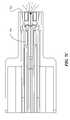
- FIG. 1is a cross-sectional side view of an injector-igniter according to a representative embodiment
- FIG. 2is an enlarged partial cross-section of the injector-igniter shown in FIG. 1 illustrating the construction of a hydraulic stroke amplifier;
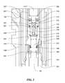
- FIG. 3is an enlarged partial cross-section of the nozzle portion of the injector-igniter shown in FIG. 1 ;
- FIG. 4is an enlarged partial cross-section view of the nozzle passage and spark gap for the injector shown in FIG. 1 ;
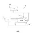
- FIG. 5is a schematic representation of a fuel injection system incorporating an injector-igniter and thermochemical regenerator
- FIG. 6is a schematic representation of a fuel injection system incorporating an injector-igniter and thermochemical regenerator with energy storage;
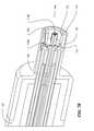
- FIG. 7Ais a cross-sectional side view of an injector-igniter according to a representative embodiment
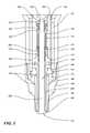
- FIG. 7Bis an enlarged cross-sectional perspective view of the nozzle portion of the injector-igniter shown in FIG. 7A ;
- FIG. 7Cis an enlarged cross-sectional side view of the nozzle portion of the injector-igniter shown in FIGS. 7A and 7B ;
- FIG. 7Dis an enlarged view of the valve assembly shown in FIG. 7A ;
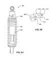
- FIG. 8Ais a side view in partial cross section of a spring and shock absorber arrangement according to a representative embodiment.
- FIG. 8Bis a schematic representation of a rectifier circuit for use with the spring and shock absorber arrangement shown in FIG. 8A .
- a fuel injection systemcomprises an injector-igniter and a fuel tank in fluid communication with the injector-igniter.
- the injector-igniterincludes an injector housing and a valve assembly.
- the valve assemblyincludes a valve and a valve seat electrode located within the injector housing.
- the valve seat electrodeforms an annular spark gap between the electrode and an electrode portion of the injector housing.
- a ceramic insulator tubemay be positioned between the injector housing and valve seat electrode.
- An actuatorsuch as a piezoelectric actuator, is disposed in the housing and connected to the valve.
- fluid communicationis provided at an injector housing location that is thermally and/or chemically isolated or sufficiently separated to reduce or eliminate the heat exchange and/or chemical contact between the actuator assembly and the valve to accommodate very cold, or corrosive, or very hot fluid and/or fuel substances.
- Some aspects of the technology described belowmay take the form of or make use of computer-executable instructions, including routines executed by a programmable computer. Those skilled in the relevant art will appreciate that the technology can be practiced on computer systems other than those shown and described below.
- the technologycan be embodied in a special-purpose computer or data processor, such as an engine control unit (ECU), engine control module (ECM), fuel system controller, or the like, that is specifically programmed, configured or constructed to perform one or more computer-executable instructions consistent with the technology described below.
- ECUengine control unit
- ECMengine control module
- fuel system controlleror the like
- the term “computer,” “processor,” or “controller” as generally used hereinrefers to any data processor and can include ECUs, ECMs, and modules, as well as Internet appliances and hand-held devices (including palm-top computers, wearable computers, cellular or mobile phones, multi-processor systems, processor-based or programmable consumer electronics, network computers, mini computers and the like). Information handled by these computers can be presented at any suitable display medium, including a CRT display, LCD, or dedicated display device or mechanism (e.g., a gauge).
- the technologycan also be practiced in distributed environments, where tasks or modules are performed by remote processing devices that are linked through a communications network.
- program modules or subroutinesmay be located in local and remote memory storage devices.
- aspects of the technology described belowmay be stored or distributed on computer-readable media, including magnetic or optically readable or removable computer disks, as well as distributed electronically over networks.
- Such networksmay include, for example and without limitation, Controller Area Networks (CAN), Local Interconnect Networks (LIN), and the like.
- CANController Area Networks
- LINLocal Interconnect Networks
- data structures and transmissions of data particular to aspects of the technologyare also encompassed within the scope of the technology.
- FIG. 1illustrates an injector-igniter 100 according to a representative embodiment that includes an injector housing 102 , an actuator 112 , a valve assembly 116 , and a stroke amplifier 114 disposed between the actuator and valve.
- Injector housing 102includes a main body 104 with a nozzle cap 108 and an end cap 106 threadably attached thereto. End cap 106 encloses an actuator body 110 , which together contain actuator 112 .
- An electrode connector 119extends laterally from the main body 104 of injector housing 102 .
- the electrode connector 119includes an inlet/electrode fitting 120 that engages the main body 104 by a suitable assembly technology such as threads and/or an interference fit sealing and clamping region.
- An elongate electrode 124is supported within inlet/electrode fitting 120 by an electrode insulator 130 and a glass seal 132 .
- Glass seal 132is operative to provide a hermetic seal between electrode 124 and inlet/electrode fitting 120 .
- Electrode connector 119further includes an electrode tip 126 that is spring loaded by electrode spring 128 to maintain electrical contact with conductor sleeve 118 .
- electrode tip 126may be welded or brazed to spring 128 .
- Conductor sleeve 118is supported between the actuator body 110 and the injector housing main body 104 .
- Conductor sleeve 118defines an inner annular gap 144 between actuator body 110 and conductor sleeve 118 .
- Conductor sleeve 118also defines an outer annular gap 146 between the main body 104 and conductor sleeve 118 .
- An inlet sleeve 122is rotatably disposed on inlet/electrode fitting 120 .
- Inlet sleeve 122includes an inlet port 134 that is in fluid communication with an annular inlet region 136 .
- Inlet port 134is adapted to receive a suitable fuel supply connection, thereby providing fuel to the injector-igniter 100 .
- Inlet sleeve 122is retained on inlet/electrode fitting 120 by a retaining ring 138 , and one or more insulator seals, such as a pair of O-rings 140 are operative to seal inlet sleeve 122 against the inlet/electrode fitting 120 .
- Inlet region 136is in fluid communication with both the inner and outer annular gaps 144 , 146 as well as valve assembly 116 , as explained more fully below. Accordingly, fuel fills the inlet region 136 , inner annular gap 144 , and outer annular gap 146 .
- the fuele.g., compressed natural gas, propane, ethane, or butane
- fuel selectionsare occasionally modified with crack healing agents that penetrate incipient cracks in polymer, glass or ceramic insulators to provide a smoothed resurfacing and/or restoration of insulative performance and endurance.
- the ignition componentsare insulated with solid insulators such as glass or ceramic.
- electrode 124is in electrical communication with conductor sleeve 118 via electrode tip 126 .
- Conductor sleeve 118is also in electrical communication with the valve seat electrode 160 , which is part of valve assembly 116 .
- actuator 112is a stacked piezoelectric actuator which may provide the desired actuation force and motion magnitude or may operate through stroke amplifier 114 to actuate valve assembly 116 .
- actuator 112is described in this embodiment as a piezoelectric device, other suitable actuators may be used.
- actuator 112may be a solenoid, magnetostrictive, piezoelectric, pneumatic, or hydraulic actuator, for example.
- FIG. 2it can be appreciated that actuator 112 acts against an actuator seat 238 which in turn actuates stroke amplifier 114 .
- piezoelectric actuatorsprovide high actuation force (e.g., approx. 600N), they have limited linear displacement capabilities (e.g., 130 to 230 microns).
- Stroke amplifier 114includes an amplifier housing 210 which contains an anvil 212 that interfaces with actuator seat 238 .
- actuator seat 238 and anvil 212include spherical surfaces to facilitate self-alignment of the actuator 112 and the stroke amplifier 114 .
- Anvil 212in turn acts against amplifier piston 222 .
- Amplifier piston 222has a diameter D 1 which acts against hydraulic fluid in working volume 230 .
- Working volume 230contains a hydraulic fluid which is displaced by amplifier piston 222 upon actuation by actuator 112 .
- the displaced working fluid under amplifier piston 222is displaced into a smaller diameter D 2 corresponding to drive piston 234 .
- a small displacement of amplifier piston 222is amplified by a ratio of the effective areas of amplifier piston 222 and drive piston 234 .
- D 1is 7 mm and D 2 is 5.2 mm providing an amplification ratio of 1.8:1 (ideal for some applications and may be adjusted to larger or smaller rations for other applications). It is expected that some stroke amplification may be lost or gained due to thermal expansion, compressibility of the hydraulic fluid and/or leakage.
- Amplifier piston 222is biased away from working volume 230 by amplifier spring 224 .
- drive piston 234is biased away from working volume 230 by drive piston spring 236 .
- magnets and/or springsmay be used.
- both the amplifier spring 224 and drive piston spring 236comprise Belleville washers stacked together to provide the desired spring rate. Biasing both the amplifier piston 222 and drive piston 234 away from working volume 230 insures that full stroke amplification is available for multiple injection cycles. Furthermore, spring biasing the pistons in this manner helps to reduce backlash in the amplifier system. Stroke amplifier 114 also absorbs effects due to thermal growth, thermal shrinkage, part geometry changes due to loads, gravitational effects, etc. that would otherwise limit the working limits or actuator functionality of the device.
- Anvil 212includes anvil passages 214 that allow hydraulic fluid to flow from reservoir volume 232 into a check valve insert 216 included in amplifier piston 222 . Hydraulic fluid flows into check valve passage 226 and through check seat 228 to fill the working volume 230 . The check ball 218 is positioned adjacent to check valve seat 228 and is operative to close check passage 226 upon actuation of amplifier piston 222 . Reservoir volume 232 extends around actuator 112 and around a portion of amplifier housing 210 . Any hydraulic fluid that escapes past diameter D 2 of drive piston 234 is returned to reservoir volume 232 via return passage 220 .
- stroke amplifier 114is a self-contained assembly, the components of which are housed in amplifier housing 210 and retained therein by retainer rings 240 and 242 .
- the stroke amplifier 114is inserted into actuator body 110 .
- Drive piston 234pushes against plunger 192 to actuate valve assembly 116 (as shown in FIG. 1 ).
- plunger 192 as well as insulator sleeve 142are made from an insulating material, such as ceramic, to isolate the actuator 112 and stroke amplifier 114 from the conductor sleeve 118 (also see FIG. 2 ).
- the ceramicmay be a dielectric glass-ceramic composition or alumina ceramic (Al 2 O 3 ), or it may be a high-temperature composite such as layered flexible mica, glass and/or polyimide film and polyimide varnish, for example.
- Valve assembly 116includes a valve 150 slidably disposed in a valve seat electrode 160 . As mentioned above, valve seat electrode 160 is in electrical communication with conductor sleeve 118 .
- valve 150is also isolated from the stroke amplifier 114 by insulator sleeve 142 and plunger 192 .
- plunger 192pushes against valve 150 thereby moving valve head 152 away from valve seat 166 .
- Valve seat electrode 160includes electrode apertures 164 which are aligned with corresponding sleeve apertures 162 . Accordingly, when valve 150 is opened, fuel supplied to outer annular gap 146 flows through sleeve apertures 162 , through electrode apertures 164 , along nozzle passage 204 and between valve seat 166 and valve head 152 .
- Valve 150includes fluted portions 200 and 202 adapted to slide within valve seat electrode 160 .
- the fluted portions 200 and 202provide a bearing surface while still allowing fuel to flow along valve 150 in nozzle passage 204 .
- Valve seat electrode 160is further insulated from injector housing 102 by insulator ring 166 and insulator tube 190 .
- Insulator ring 166is sealed against fuel leakage by O-ring/backup ring seals 172 as well as Teflon® seals 170 .
- insulator ring 166is brazed to valve seat electrode 160 at weld 168 .
- valve 150is pressure balanced within valve seat electrode 160 by way of bellows 174 .
- Bellows 174also provides a seal against fuel leakage.
- bellows 174is welded (e.g., laser welded) to valve seat electrode 160 .
- the weldsare reinforced with weld rings 176 and 178 , which help prevent additional stress from internal pressure.
- Valve 150is maintained in a normally closed position by valve spring 186 , which rests against spring seat 180 .
- the valve spring 186is retained on valve 150 by a spring retainer 182 and clip 184 .
- Clip 184is disposed in groove 154 which is formed around a distal end of valve 150 .
- nozzle cap 108includes an electrode portion 194 . It should also be appreciated that nozzle cap 108 is in contact with an engine's cylinder head and sealed thereto with a head seal ring 198 . Accordingly electrode portion 194 is grounded to the engine. As described above, the valve seat electrode 160 is in electrical communication with electrode 124 . Thus, voltage (e.g., ⁇ 200 VDC) applied to electrode 124 travels down electrode 124 , through electrode tip 126 , along conductor sleeve 118 , and ultimately down valve seat electrode 160 to valve seat 166 . Therefore, valve seat 166 and electrode portion 194 define an annular spark gap 196 .
- voltagee.g., ⁇ 200 VDC
- FIG. 5is a schematic representation of a fuel injection system 500 that includes fuel tank 502 which is operatively connected to an injector-igniter 506 .
- Injector-igniter 506is operative to direct-inject fuel into an engine 504 .
- injector-igniter 506is operative to provide a spark thereby initiating combustion of the fuel.
- Injector-igniter 506may be the injector-igniter 100 described herein or another suitable injector-igniter.
- the injector-igniteris operative to provide ignition energy such as thrust ions or corona discharge.
- the fuel injection system 500also includes a thermochemical reactor 508 to provide supplemental hydrogen for combustion enhancement.
- thermochemical reactorsare described in co-pending U.S. patent application Ser. No. 13/027,198, entitled COUPLED THERMOCHEMICAL REACTORS AND ENGINES, AND ASSOCIATED SYSTEMS AND METHODS, filed Feb. 14, 2011, the disclosure of which is hereby incorporated by reference in its entirety.
- An engine control unit 510communicates with the engine sensors and controls as well as injector-igniter 506 and thermochemical reactor 508 .
- thermochemical reactor assembly 508includes an accumulator volume for storage of chemical and/or pressure and/or thermal potential energy.
- Embodiment 600 of FIG. 6shows accumulator volume 618 for storing potential energy such as chemical, temperature, and pressure contributions to potential energy.
- Accumulator 618stores hot hydrogen at high temperature such as 700 to 1500° C. (1300 to 2700° F.).
- Such hydrogen inventory in volume 618includes hydrogen that has been separated by galvanic proton impetus to deliver pressurized hydrogen into this accumulator space around cathode zone 616 after production of such hydrogen in conjunction with anode zone 657 from a hydrogen donor formula or mixture that may include substances such as ammonia, urea, a fuel alcohol, formic acid, water, oxygen, or various hydrocarbons such as natural gas or other petroleum products that are delivered by conduit 653 .
- Heat from a suitable source such as the exhaust 633 of engine 504may be utilized to preheat hydrogen donor substances in heat exchanger arrangements within a suitably reinforced and insulated case 631 as partially depicted in FIG. 6 .
- Suitable heat exchange arrangementsinclude systems such as the helical coil surrounding pressure containment tube or vessel 622 as shown prior to admission of such hydrogen donor fluid into the tubular bore of accumulator 656 within tube or pressure vessel 655 .
- Additional heatmay be added by resistance or inductive heater 662 using electricity from a suitable source such as the regeneratively produced electricity from stopping a vehicle and/or from regenerative shock absorbers and/or suspension springs.
- FIGS. 8A and 8Billustrate a typical assembly 800 that includes a spring and shock absorber arrangement for serving between components such as vehicle carriage and traction or support components.
- Embodiment 800includes micro-controller 806 and provides regenerative electricity production as a result of the actions of shock absorber 804 and/or spring 802 including electrostatic, electromagnetic, electro-pneumatic, electro-hydraulic and/or piezoelectric generation of electricity.
- electricity such as direct, pulsed direct, and/or alternating currentis produced by assembly 800 such as depicted by power 804 is rectified by full wave bridge 808 and delivered to suitable storage such as a battery and/or capacitor 810 and thus through resistance and/or inductive coupling 812 , 814 to applications such as heating the reactor-separator 655 within assembly 600 of FIG. 6 as controlled through switches 816 and/or 818 .
- hot gases including mixtures not entirely converted to hydrogensuch as portions of feedstock fuels, carbon monoxide, carbon dioxide, nitrogen, and/or water vapor are provided from accumulator 656 to injector 506 through suitably insulated and or cooled conduit 666 .
- High pressure hydrogenis delivered through insulated or cooled conduit 664 to injector 506 .
- injector type 700 shown in FIGS. 7A-7Dmay be advantageous in certain embodiments to utilize the injector type 700 shown in FIGS. 7A-7D to deliver gases that have been cooled into engine 504 before top dead center (TDC) to perform cooling of the oxidant such as air and thus reduce the back work of compression and thus to provide improved brake mean effective pressure (BMEP) in the operation of engine 504 .
- hot hydrogenis delivered as a high pressure expansion heating substance at or after TDC to increase the BMEP of engine 506 and to improve the combustion characteristics including acceleration of the ignition and completion of combustion of fuel delivered through conduits 664 and 666 .
- Injector 700utilizes a suitable valve operator such as a pneumatic, hydraulic, electromagnetic, magnetostrictive or piezoelectric assembly 702 to control the opening and/or closing of fuel control valve 704 which is shown in FIGS. 7B and 7C .
- Fuels from accumulator 656may be cooled including achievement of temperatures that approach cryogenic methane or hydrogen in instances that a suitable fuel tank 502 is utilized for such storage.
- pressurized fluid from conduit 666is selected by a rapid response valve assembly such as 780 which may be actuated by a pneumatic, hydraulic, electromagnetic, magnetostrictive, or piezoelectric actuator 782 (see FIG. 7D ) to produce output through linkage 788 and mechanically amplified stroke through linkage 790 by lever linkage 784 to move a suitable valve such as a spool valve within case 792 to deliver fluid (e.g. hot high pressure hydrogen from accumulator 618 through conduit 664 or suitably conditioned such as cooled fluid through conduit 666 to conduit 793 for injection controlled by valve 704 as shown.
- fluide.g. hot high pressure hydrogen from accumulator 618 through conduit 664 or suitably conditioned such as cooled fluid through conduit 666 to conduit 793 for injection controlled by valve 704 as shown.
- Valve assembly 780is provided at a suitable location such as on insulator 721 as shown for purposes of functionally isolating (e.g. hot, corrosive, or cold) fluids provided to the combustion chamber of engine 504 as controlled by operation of valve 704 .
- another fluid that is delivered through fitting 734 from pressure regulator 732such as may be used to cool and/or provide deliveries of incipient crack repair agents such as activated monomers and/or precursors for polymeric, glass, ceramic, or composite insulation systems such as 720 which may include components that also may provide functions such as charge storage as capacitors.
- valve 704is opened and/or closed by actuator 702 .
- a piezoelectric stack 702 with sufficiently long actuation strokeis selected and is controlled by adaptively adjusted applied voltage to open valve 704 variable distances to control the rate of fluid flow such as fuel delivery into the combustion chamber of engine 504 .
- instrumentationsuch as may be provided and/or relayed to microcontroller 730 by components 712 such as light pipes or fiber optics 712 A monitor the opening from the valve seat portion of in electrode component 710 to control actuator 702 to and/or flow delivered past valve 704 as shown.
- Additional instrumentation 712 Bmonitors and relays combustion chamber information to controller 730 such as temperature, pressure, injected fluid penetration and patterns including intake, compression, combustion, and exhaust events.
- Injection and/or ignition of fuel delivered through valve 702is through the annular pathway and/or channels between electrode features such as 732 (see FIG. 7C ) which may produce swirl or other shapes of fluid such as fuel projections into combustion chamber 740 .
- Ignitionmay be selected from spark, ion thrusting, and/or corona discharge within combustion chamber 740 .
- ion production and acceleration starting with ion current development between relatively small gaps between one or more tips 712 and a suitably shaped counter electrode 714provides ion thrusting of adaptively adjusted ion populations by controller 730 in response to information such as may be relayed through filaments 712 A and/or 712 B.
- Corona dischargemay follow such ion launch patterns for further ion production and/or ionizing radiation accelerated initiation and/or completion of combustion operations.
- low voltage electricitymay be utilized to operate system 700 and may be supplied from suitable circuits within controller assembly 730 or at other suitable locations including production of high voltage for spark, ion thrusting and/or corona ignition by selected transformer elements and cells of assembly 722 A- 722 R as shown with abbreviated designations of such inductive windings.
- High voltageis delivered through one or more insulated conductors 724 to conductor tube 726 and thus to electrode 710 as shown for such applications.
- a fuel injection systemcomprising:
- an injector-igniterincluding:
- a fuel tankin fluid communication with the injector-igniter.
- thermochemical reactoroperatively coupled to the injector-igniter.
- a fuel injection systemcomprising:
- an injector-igniterincluding:
- thermochemical reactoroperatively coupled to the injector-igniter.
- An injector-ignitercomprising:
- valve assemblyincluding a valve and a valve seat electrode located within the injector housing and forming an annular spark gap between the valve seat electrode and an electrode portion of the injector housing;
- a conductor sleevesupported between the actuator and injector housing, and electrically connected to the valve seat electrode.
Landscapes
- Engineering & Computer Science (AREA)
- Chemical & Material Sciences (AREA)
- Combustion & Propulsion (AREA)
- Mechanical Engineering (AREA)
- General Engineering & Computer Science (AREA)
- Physics & Mathematics (AREA)
- Optics & Photonics (AREA)
- Fuel-Injection Apparatus (AREA)
- Ignition Installations For Internal Combustion Engines (AREA)
Abstract
Description
- an injector housing;
- an outwardly opening valve assembly including a valve and a valve seat electrode located within the injector housing and forming an annular spark gap between the valve seat electrode and an electrode portion of the injector housing; and
- an actuator disposed in the housing operatively connected to the valve; and
- an injector housing;
- an outwardly opening valve assembly including a valve and a valve seat electrode located within the injector housing and forming an annular spark gap between the valve seat electrode and an electrode portion of the injector housing; and
- an actuator disposed in the housing operatively connected to the valve;
Claims (20)
Priority Applications (3)
| Application Number | Priority Date | Filing Date | Title |
|---|---|---|---|
| US13/841,548US8820293B1 (en) | 2013-03-15 | 2013-03-15 | Injector-igniter with thermochemical regeneration |
| PCT/US2014/029154WO2014144653A2 (en) | 2013-03-15 | 2014-03-14 | Injector-igniter with thermochemical regeneration |
| US14/445,440US20150152825A1 (en) | 2013-03-15 | 2014-07-29 | Injector-igniter with thermochemical regeneration |
Applications Claiming Priority (1)
| Application Number | Priority Date | Filing Date | Title |
|---|---|---|---|
| US13/841,548US8820293B1 (en) | 2013-03-15 | 2013-03-15 | Injector-igniter with thermochemical regeneration |
Related Child Applications (1)
| Application Number | Title | Priority Date | Filing Date |
|---|---|---|---|
| US14/445,440ContinuationUS20150152825A1 (en) | 2013-03-15 | 2014-07-29 | Injector-igniter with thermochemical regeneration |
Publications (2)
| Publication Number | Publication Date |
|---|---|
| US8820293B1true US8820293B1 (en) | 2014-09-02 |
| US20140261323A1 US20140261323A1 (en) | 2014-09-18 |
Family
ID=51399826
Family Applications (2)
| Application Number | Title | Priority Date | Filing Date |
|---|---|---|---|
| US13/841,548Expired - Fee RelatedUS8820293B1 (en) | 2013-03-15 | 2013-03-15 | Injector-igniter with thermochemical regeneration |
| US14/445,440AbandonedUS20150152825A1 (en) | 2013-03-15 | 2014-07-29 | Injector-igniter with thermochemical regeneration |
Family Applications After (1)
| Application Number | Title | Priority Date | Filing Date |
|---|---|---|---|
| US14/445,440AbandonedUS20150152825A1 (en) | 2013-03-15 | 2014-07-29 | Injector-igniter with thermochemical regeneration |
Country Status (2)
| Country | Link |
|---|---|
| US (2) | US8820293B1 (en) |
| WO (1) | WO2014144653A2 (en) |
Cited By (7)
| Publication number | Priority date | Publication date | Assignee | Title |
|---|---|---|---|---|
| US20120260899A1 (en)* | 2011-04-12 | 2012-10-18 | Ngk Spark Plug Co., Ltd. | Ignition system |
| US20150152825A1 (en)* | 2013-03-15 | 2015-06-04 | Mcalister Technologies, Llc | Injector-igniter with thermochemical regeneration |
| US20150315990A1 (en)* | 2014-04-30 | 2015-11-05 | Fire Chariot, Llc | Diesel engine combustion and temperature management system |
| US9562500B2 (en) | 2013-03-15 | 2017-02-07 | Mcalister Technologies, Llc | Injector-igniter with fuel characterization |
| US20170159625A1 (en)* | 2015-12-08 | 2017-06-08 | Caterpillar Inc. | Injector seals for dual fuel application |
| CN107882671A (en)* | 2017-10-17 | 2018-04-06 | 天津航空机电有限公司 | A kind of inside carries the ignition electric nozzle of oil circuit |
| US11891962B1 (en)* | 2022-08-25 | 2024-02-06 | Caterpillar Inc. | Gaseous fuel engine system operating strategy including hydrogen fueling amount based on performance target |
Families Citing this family (1)
| Publication number | Priority date | Publication date | Assignee | Title |
|---|---|---|---|---|
| WO2019055462A1 (en)* | 2017-09-14 | 2019-03-21 | Bloom Energy Corporation | Internal light off mechanism for solid oxide fuel cell system startup using a spark ignitor |
Citations (256)
| Publication number | Priority date | Publication date | Assignee | Title |
|---|---|---|---|---|
| US1307088A (en) | 1919-06-17 | X- s spark-plug | ||
| US1451384A (en) | 1920-04-19 | 1923-04-10 | Whyte John | Solenoid-controlled fuel injection and ignition valve |
| US1765237A (en) | 1928-02-17 | 1930-06-17 | Fred H King | Triple-cam-drive gasoline engine |
| US2255203A (en) | 1940-02-28 | 1941-09-09 | Wright Aeronautical Corp | Fuel injection spark plug |
| US2681212A (en) | 1951-05-16 | 1954-06-15 | Fenley Thomas Douglas | Dual fuel carburetion |
| US2744507A (en) | 1951-02-07 | 1956-05-08 | Inconex Handelsges M B H Fur I | Means for treating liquid fuel before its injection into the working cylinder of internal combustion engines |
| US2864974A (en) | 1954-10-19 | 1958-12-16 | Smitsvonk N V Res Laboratorieu | Ignition system for internal combustion engines |
| US3058453A (en) | 1960-02-15 | 1962-10-16 | Walker Mfg Co | Fuel injector-igniter |
| US3060912A (en) | 1960-02-15 | 1962-10-30 | Walker Mfg Co | Fuel injector-igniter |
| US3081758A (en) | 1960-05-02 | 1963-03-19 | Walker Mfg Co | Pressure actuated fuel injector |
| US3243335A (en) | 1963-03-13 | 1966-03-29 | Samuel P Faile | Ceramic product and process of producing it |
| GB1038490A (en) | 1963-02-18 | 1966-08-10 | Papst Hermann | Fuel injection nozzles for internal combustion engines |
| US3373724A (en) | 1964-02-10 | 1968-03-19 | Papst Hermann | Fuel injection and ignition device for internal combustion engines |
| US3520961A (en) | 1967-05-12 | 1970-07-21 | Yuken Ind Co Ltd | Method for manufacturing ceramic articles |
| US3551738A (en) | 1969-01-30 | 1970-12-29 | Westinghouse Electric Corp | Condenser discharge lamp circuit with a pulse forming network and a keep alive circuit |
| US3594877A (en) | 1969-10-24 | 1971-07-27 | Yuken Kogyo Co Ltd | Apparatus for manufacturing ceramic articles |
| US3608050A (en) | 1969-09-12 | 1971-09-21 | Union Carbide Corp | Production of single crystal sapphire by carefully controlled cooling from a melt of alumina |
| US3689293A (en) | 1970-07-08 | 1972-09-05 | Corning Glass Works | Mica glass-ceramics |
| US3866074A (en) | 1973-07-23 | 1975-02-11 | David A Smith | Magnetic spark spreader |
| US3926169A (en) | 1974-06-21 | 1975-12-16 | Fuel Injection Dev Corp | Combined fuel vapor injector and igniter system for internal combustion engines |
| US3931438A (en) | 1971-11-08 | 1976-01-06 | Corning Glass Works | Differential densification strengthening of glass-ceramics |
| US3960995A (en) | 1970-05-13 | 1976-06-01 | Kourkene Jacques P | Method for prestressing a body of ceramic material |
| US3976039A (en) | 1973-06-06 | 1976-08-24 | Regie Nationale Des Usines Renault | Internal combustion engine with stratified charge |
| US3997352A (en) | 1975-09-29 | 1976-12-14 | Corning Glass Works | Mica-spodumene glass-ceramic articles |
| US4066046A (en) | 1974-07-29 | 1978-01-03 | Mcalister Roy E | Method and apparatus for fuel injection-spark ignition system for an internal combustion engine |
| US4087719A (en) | 1976-03-04 | 1978-05-02 | Massachusetts Institute Of Technology | Spark plug |
| US4095580A (en) | 1976-10-22 | 1978-06-20 | The United States Of America As Represented By The United States Department Of Energy | Pulse-actuated fuel-injection spark plug |
| US4122816A (en) | 1976-04-01 | 1978-10-31 | The United States Of America As Represented By The Administrator Of The National Aeronautics And Space Administration | Plasma igniter for internal combustion engine |
| US4135481A (en) | 1976-11-26 | 1979-01-23 | Cornell Research Foundation, Inc. | Exhaust gas recirculation pre-stratified charge |
| US4203393A (en) | 1979-01-04 | 1980-05-20 | Ford Motor Company | Plasma jet ignition engine and method |
| US4330732A (en) | 1980-03-14 | 1982-05-18 | Purification Sciences Inc. | Plasma ceramic coating to supply uniform sparking action in combustion engines |
| US4332223A (en) | 1980-08-29 | 1982-06-01 | Dalton James M | Plasma fuel ignitors |
| US4364342A (en) | 1980-10-01 | 1982-12-21 | Ford Motor Company | Ignition system employing plasma spray |
| US4377455A (en) | 1981-07-22 | 1983-03-22 | Olin Corporation | V-Shaped sandwich-type cell with reticulate electodes |
| US4381740A (en) | 1980-05-05 | 1983-05-03 | Crocker Alfred J | Reciprocating engine |
| US4382189A (en) | 1979-05-25 | 1983-05-03 | Wilson John B | Hydrogen supplemented diesel electric locomotive |
| US4448160A (en) | 1982-03-15 | 1984-05-15 | Vosper George W | Fuel injector |
| US4469160A (en) | 1981-12-23 | 1984-09-04 | United Technologies Corporation | Single crystal solidification using multiple seeds |
| US4483485A (en) | 1981-12-11 | 1984-11-20 | Aisan Kogyo kabuskiki Kaisha | Electromagnetic fuel injector |
| US4511612A (en) | 1981-08-21 | 1985-04-16 | Motoren-Und Turbinen-Union Munchen Gmbh | Multiple-layer wall for a hollow body and method for manufacturing same |
| US4528270A (en) | 1982-11-02 | 1985-07-09 | Kabushiki Kaisya Advance Kaihatsu Kenkyujo | Electrochemical method for detection and classification of microbial cell |
| US4536452A (en) | 1983-10-24 | 1985-08-20 | Corning Glass Works | Spontaneously-formed machinable glass-ceramics |
| US4567857A (en) | 1980-02-26 | 1986-02-04 | The United States Of America As Represented By The Administrator Of The National Aeronautics And Space Administration | Combustion engine system |
| US4574037A (en) | 1983-04-12 | 1986-03-04 | Kanegafuchi Kagaku Kogyo Kabushiki Kaisha | Vertical type electrolytic cell and electrolytic process using the same |
| DE3443022A1 (en) | 1984-11-26 | 1986-05-28 | Walter Neumarkt am Wallersee Dolzer | Transistor ignition system |
| US4677960A (en) | 1984-12-31 | 1987-07-07 | Combustion Electromagnetics, Inc. | High efficiency voltage doubling ignition coil for CD system producing pulsed plasma type ignition |
| US4688538A (en) | 1984-12-31 | 1987-08-25 | Combustion Electromagnetics, Inc. | Rapid pulsed multiple pulse ignition and high efficiency power inverter with controlled output characteristics |
| US4733646A (en) | 1986-04-30 | 1988-03-29 | Aisin Seiki Kabushiki Kaisha | Automotive ignition systems |
| US4736718A (en) | 1987-03-19 | 1988-04-12 | Linder Henry C | Combustion control system for internal combustion engines |
| US4742265A (en) | 1986-11-12 | 1988-05-03 | Ford Motor Company | Spark plug center electrode of alloy material including aluminum and chromium |
| US4760820A (en) | 1983-07-20 | 1988-08-02 | Luigi Tozzi | Plasma jet ignition apparatus |
| US4760818A (en) | 1986-12-16 | 1988-08-02 | Allied Corporation | Vapor phase injector |
| US4774914A (en) | 1985-09-24 | 1988-10-04 | Combustion Electromagnetics, Inc. | Electromagnetic ignition--an ignition system producing a large size and intense capacitive and inductive spark with an intense electromagnetic field feeding the spark |
| US4774919A (en) | 1986-09-08 | 1988-10-04 | Yamaha Hatsudoki Kabushiki Kaisha | Combustion chamber importing system for two-cycle diesel engine |
| US4834033A (en) | 1986-10-31 | 1989-05-30 | Larsen Melvin J | Apparatus and method for a balanced internal combustion engine coupled to a drive shaft |
| US4841925A (en) | 1986-12-22 | 1989-06-27 | Combustion Electromagnetics, Inc. | Enhanced flame ignition for hydrocarbon fuels |
| US4922883A (en) | 1987-10-29 | 1990-05-08 | Aisin Seiki Kabushiki Kaisha | Multi spark ignition system |
| US4932263A (en) | 1989-06-26 | 1990-06-12 | General Motors Corporation | Temperature compensated fiber optic pressure sensor |
| US4967708A (en) | 1987-09-17 | 1990-11-06 | Robert Bosch Gmbh | Fuel injection valve |
| US4977873A (en) | 1989-06-08 | 1990-12-18 | Clifford L. Elmore | Timing chamber ignition method and apparatus |
| US4982708A (en) | 1989-06-22 | 1991-01-08 | Robert Bosch Gmbh | Fuel injection nozzle for internal combustion engines |
| US5034852A (en) | 1989-11-06 | 1991-07-23 | Raytheon Company | Gasket for a hollow core module |
| US5055435A (en) | 1987-03-24 | 1991-10-08 | Ngk Insulators, Ltd. | Ceramic materials to be insert-cast |
| US5056496A (en) | 1989-03-14 | 1991-10-15 | Nippondenso Co., Ltd. | Ignition system of multispark type |
| US5072617A (en) | 1990-10-30 | 1991-12-17 | The United States Of America As Represented By The United States Department Of Energy | Fiber-optic liquid level sensor |
| US5076223A (en) | 1990-03-30 | 1991-12-31 | Board Of Regents, The University Of Texas System | Miniature railgun engine ignitor |
| US5095742A (en) | 1990-08-24 | 1992-03-17 | Ford Motor Company | Determining crankshaft acceleration in an internal combustion engine |
| US5109817A (en) | 1990-11-13 | 1992-05-05 | Altronic, Inc. | Catalytic-compression timed ignition |
| US5131376A (en) | 1991-04-12 | 1992-07-21 | Combustion Electronics, Inc. | Distributorless capacitive discharge ignition system |
| US5193515A (en) | 1991-03-12 | 1993-03-16 | Aisin Seiki Kabushiki Kaisha | Ignition system for an engine |
| US5207208A (en) | 1991-09-06 | 1993-05-04 | Combustion Electromagnetics Inc. | Integrated converter high power CD ignition |
| US5211142A (en) | 1990-03-30 | 1993-05-18 | Board Of Regents, The University Of Texas System | Miniature railgun engine ignitor |
| US5220901A (en) | 1991-10-09 | 1993-06-22 | Mitsubishi Denki Kabushiki Kaisha | Capacitor discharge ignition system with inductively extended discharge time |
| US5267601A (en) | 1988-11-10 | 1993-12-07 | Lanxide Technology Company, Lp | Method for forming a metal matrix composite body by an outside-in spontaneous infiltration process, and products produced thereby |
| US5297518A (en) | 1992-08-10 | 1994-03-29 | Cherry Mark A | Mass controlled compression timed ignition method and igniter |
| US5305360A (en) | 1993-02-16 | 1994-04-19 | Westinghouse Electric Corp. | Process for decontaminating a nuclear reactor coolant system |
| US5328094A (en) | 1993-02-11 | 1994-07-12 | General Motors Corporation | Fuel injector and check valve |
| US5377633A (en) | 1993-07-12 | 1995-01-03 | Siemens Automotive L.P. | Railplug direct injector/ignitor assembly |
| US5390546A (en) | 1993-07-01 | 1995-02-21 | Wlodarczyk; Marek T. | Fiber optic diaphragm sensors for engine knock and misfire detection |
| US5392745A (en) | 1987-02-20 | 1995-02-28 | Servojet Electric Systems, Ltd. | Expanding cloud fuel injecting system |
| US5394838A (en) | 1992-07-24 | 1995-03-07 | American Fuel Systems, Inc. | Vaporized fuel injection system |
| US5421299A (en) | 1992-08-10 | 1995-06-06 | Cherry; Mark A. | Compression timed pre-chamber flame distributing igniter for internal combustion engines |
| US5421195A (en) | 1993-07-01 | 1995-06-06 | Wlodarczyk; Marek T. | Fiber optic microbend sensor for engine knock and misfire detection |
| US5435286A (en) | 1994-05-02 | 1995-07-25 | Cummins Engine Company, Inc. | Ball link assembly for vehicle engine drive trains |
| US5439532A (en) | 1992-06-30 | 1995-08-08 | Jx Crystals, Inc. | Cylindrical electric power generator using low bandgap thermophotovolatic cells and a regenerative hydrocarbon gas burner |
| US5456241A (en) | 1993-05-25 | 1995-10-10 | Combustion Electromagnetics, Inc. | Optimized high power high energy ignition system |
| US5475772A (en) | 1994-06-02 | 1995-12-12 | Honeywell Inc. | Spatial filter for improving polarization extinction ratio in a proton exchange wave guide device |
| US5497744A (en) | 1993-11-29 | 1996-03-12 | Toyota Jidosha Kabushiki Kaisha | Fuel injector with an integrated spark plug for a direct injection type engine |
| US5517961A (en) | 1995-02-27 | 1996-05-21 | Combustion Electromagnetics, Inc. | Engine with flow coupled spark discharge |
| US5531199A (en)* | 1992-05-11 | 1996-07-02 | United Fuels Limited | Internal combustion engines |
| US5549746A (en) | 1993-09-24 | 1996-08-27 | General Electric Company | Solid state thermal conversion of polycrystalline alumina to sapphire using a seed crystal |
| US5584490A (en) | 1994-08-04 | 1996-12-17 | Nippon Gasket Co., Ltd. | Metal gasket with coolant contact areas |
| US5588299A (en) | 1993-05-26 | 1996-12-31 | Simmonds Precision Engine Systems, Inc. | Electrostatic fuel injector body with igniter electrodes formed in the housing |
| US5605125A (en) | 1994-11-18 | 1997-02-25 | Yaoita; Yasuhito | Direct fuel injection stratified charge engine |
| US5607106A (en) | 1994-08-10 | 1997-03-04 | Cummins Engine Company | Low inertia, wear-resistant valve for engine fuel injection systems |
| US5662389A (en) | 1996-09-10 | 1997-09-02 | New York Air Brake Corporation | Variable load EP brake control system |
| US5676026A (en) | 1994-09-20 | 1997-10-14 | Honda Giken Kogyo Kabushiki Kaisha | Hydraulic pressure control system |
| US5694761A (en) | 1993-07-07 | 1997-12-09 | Griffin, Jr.; Arthur T. | Combustor cooling for gas turbine engines |
| US5699253A (en) | 1995-04-05 | 1997-12-16 | Ford Global Technologies, Inc. | Nonlinear dynamic transform for correction of crankshaft acceleration having torsional oscillations |
| US5702761A (en) | 1994-04-29 | 1997-12-30 | Mcdonnell Douglas Corporation | Surface protection of porous ceramic bodies |
| US5704321A (en) | 1996-05-29 | 1998-01-06 | The Trustees Of Princeton University | Traveling spark ignition system |
| US5715788A (en) | 1996-07-29 | 1998-02-10 | Cummins Engine Company, Inc. | Integrated fuel injector and ignitor assembly |
| US5738818A (en) | 1996-08-28 | 1998-04-14 | Northrop Grumman Corporation | Compression/injection molding of polymer-derived fiber reinforced ceramic matrix composite materials |
| US5746171A (en) | 1995-02-06 | 1998-05-05 | Yaoita; Yasuhito | Direct fuel injection stratified charge engine |
| US5767026A (en) | 1994-10-04 | 1998-06-16 | Agency Of Industrial Science And Technology | Silicon nitride ceramic and process for forming the same |
| US5797427A (en) | 1996-10-11 | 1998-08-25 | Buescher; Alfred J. | Fuel injector check valve |
| US5806581A (en) | 1995-12-21 | 1998-09-15 | Modine Manufacturing Company | Oil cooler with a retained, blow-out proof, and extrusion resistant gasket configuration |
| US5853175A (en) | 1996-09-30 | 1998-12-29 | Ishikawa Gasket Co., Ltd. | Cylinder head gasket with fluid flow path |
| US5863326A (en) | 1996-07-03 | 1999-01-26 | Cermet, Inc. | Pressurized skull crucible for crystal growth using the Czochralski technique |
| US5876659A (en) | 1993-06-25 | 1999-03-02 | Hitachi, Ltd. | Process for producing fiber reinforced composite |
| US5915272A (en) | 1993-08-02 | 1999-06-22 | Motorola Inc. | Method of detecting low compression pressure responsive to crankshaft acceleration measurement and apparatus therefor |
| US5941207A (en) | 1997-09-08 | 1999-08-24 | Ford Global Technologies, Inc. | Direct injection spark ignition engine |
| US5975433A (en) | 1996-11-08 | 1999-11-02 | Zexel Corporation | Fuel injection nozzle with rotary valve |
| US5975032A (en) | 1996-06-07 | 1999-11-02 | Sanshin Kogyo Kabushiki Kaisha | Engine cooling system |
| US5983855A (en) | 1996-09-18 | 1999-11-16 | Robert Bosch Gmbh | Fuel injection valve with integrated spark plug |
| US6017390A (en) | 1996-07-24 | 2000-01-25 | The Regents Of The University Of California | Growth of oriented crystals at polymerized membranes |
| US6026568A (en) | 1995-08-16 | 2000-02-22 | Northrop Grumman | High efficiency low-pollution engine |
| US6062498A (en) | 1998-04-27 | 2000-05-16 | Stanadyne Automotive Corp. | Fuel injector with at least one movable needle-guide |
| US6065692A (en) | 1999-06-09 | 2000-05-23 | Siemens Automotive Corporation | Valve seat subassembly for fuel injector |
| US6081183A (en) | 1998-04-24 | 2000-06-27 | Eaton Corporation | Resistor adapted for use in forced ventilation dynamic braking applications |
| US6085990A (en) | 1997-01-22 | 2000-07-11 | Daimlerchrysler Ag | Piezoelectric injector for fuel-injection systems of internal combustion engines |
| US6092507A (en) | 1996-08-08 | 2000-07-25 | Robert Bosch Gmbh | Control arrangement for a direct-injecting internal combustion engine |
| US6092501A (en) | 1997-05-20 | 2000-07-25 | Nissan Motor Co., Ltd. | Direct injection gasoline engine with stratified charge combustion and homogeneous charge combustion |
| US6093338A (en) | 1997-08-21 | 2000-07-25 | Kabushiki Kaisha Toyota Chuo Kenkyusho | Crystal-oriented ceramics, piezoelectric ceramics using the same, and methods for producing the same |
| US6102303A (en) | 1996-03-29 | 2000-08-15 | Siemens Automotive Corporation | Fuel injector with internal heater |
| US6131607A (en) | 1994-08-19 | 2000-10-17 | Lucas Industries Public Limited Corporation | Delivery valve |
| US6138639A (en) | 1998-01-07 | 2000-10-31 | Nissan Motor Co., Ltd. | In-cylinder direct-injection spark-ignition engine |
| US6173913B1 (en) | 1999-08-25 | 2001-01-16 | Caterpillar Inc. | Ceramic check for a fuel injector |
| US6185355B1 (en) | 1998-09-01 | 2001-02-06 | Henry H. Hung | Process for making high yield, DC stable proton exchanged waveguide for active integrated optic devices |
| US6186419B1 (en) | 1997-06-24 | 2001-02-13 | Robert Bosch Gmbh | Fuel injection device |
| US6189522B1 (en) | 1998-02-12 | 2001-02-20 | Ngk Spark Plug Co., Ltd. | Waste-spark engine ignition |
| US6267307B1 (en) | 1997-12-12 | 2001-07-31 | Magneti Marelli France | Fuel injector with anti-scale ceramic coating for direct injection |
| US6335065B1 (en) | 1994-11-14 | 2002-01-01 | Purdue Research Foundation | Process for slip casting textured tubular structures |
| US6338445B1 (en) | 1999-10-06 | 2002-01-15 | Delphi Technologies, Inc. | Fuel injector |
| US20020017573A1 (en) | 1994-06-06 | 2002-02-14 | Sturman Oded E. | Fuel injector with hydraulically controlled check valve |
| US6360721B1 (en) | 2000-05-23 | 2002-03-26 | Caterpillar Inc. | Fuel injector with independent control of check valve and fuel pressurization |
| US6378485B2 (en) | 1997-09-12 | 2002-04-30 | George D. Elliott | Electromagnetic fuel ram-injector and improved ignitor |
| US6386178B1 (en) | 2000-07-05 | 2002-05-14 | Visteon Global Technologies, Inc. | Electronic throttle control mechanism with gear alignment and mesh maintenance system |
| US20020084793A1 (en) | 2000-12-29 | 2002-07-04 | Hung Henry H. | Simultaneous testing of multiple optical circuits in substrate |
| US20020131171A1 (en) | 2000-10-16 | 2002-09-19 | Henry Hung | Optical fiber polarization independent non-reciprocal phase shifter |
| US20020131674A1 (en) | 2001-03-17 | 2002-09-19 | Micro Photonix Integration Corporation | Optical wavelength encoded multiple access arrangement |
| US20020131673A1 (en) | 2001-03-17 | 2002-09-19 | Micro Photonix Integration Corporation | Dynamic optical wavelength balancer |
| US20020131756A1 (en) | 2000-10-16 | 2002-09-19 | Henry Hung | Variable optical attenuator |
| US20020131706A1 (en) | 2001-03-17 | 2002-09-19 | Micro Photonix Integration Corporation | Plural wavelength optical filter apparatus and method of manufacture |
| US20020131666A1 (en) | 2001-03-19 | 2002-09-19 | Henry Hung | Non-reciprocal phase shifter |
| US6455173B1 (en) | 1997-12-09 | 2002-09-24 | Gillion Herman Marijnissen | Thermal barrier coating ceramic structure |
| US6453660B1 (en) | 2001-01-18 | 2002-09-24 | General Electric Company | Combustor mixer having plasma generating nozzle |
| US20020141692A1 (en) | 2000-10-16 | 2002-10-03 | Henry Hung | Optical network with dynamic balancing |
| US20020150375A1 (en) | 2001-04-13 | 2002-10-17 | Hung Henry H. | Crimp for providing hermetic seal for optical fiber |
| US20020151113A1 (en) | 2001-04-13 | 2002-10-17 | Hung Henry H. | Apparatus and method for suppressing false resonances in fiber optic modulators |
| US6478007B2 (en) | 2000-11-24 | 2002-11-12 | Toyota Jidosha Kabushiki Kaisha | In-cylinder-injection internal combustion engine and method of controlling in-cylinder-injection internal combustion engine |
| US6506336B1 (en) | 1999-09-01 | 2003-01-14 | Corning Incorporated | Fabrication of ultra-thinwall cordierite structures |
| US6517011B1 (en) | 2000-06-13 | 2003-02-11 | Caterpillar Inc | Fuel injector with pressurized fuel reverse flow check valve |
| US6532315B1 (en) | 2000-10-06 | 2003-03-11 | Donald J. Lenkszus | Variable chirp optical modulator having different length electrodes |
| US6536405B1 (en) | 1998-06-27 | 2003-03-25 | Robert Bosch Gmbh | Fuel injection valve with integrated spark plug |
| US6568362B2 (en) | 2001-06-12 | 2003-05-27 | Ut-Battelle, Llc | Rotating arc spark plug |
| US6578775B2 (en) | 2001-03-30 | 2003-06-17 | Denso Corporation | Fuel injector |
| US6583901B1 (en) | 2000-02-23 | 2003-06-24 | Henry Hung | Optical communications system with dynamic channel allocation |
| US6584244B2 (en) | 2001-03-17 | 2003-06-24 | Donald J. Lenkszus | Switched filter for optical applications |
| US6587239B1 (en) | 2000-02-23 | 2003-07-01 | Henry Hung | Optical fiber network having increased channel capacity |
| US6615899B1 (en) | 2002-07-12 | 2003-09-09 | Honeywell International Inc. | Method of casting a metal article having a thinwall |
| US6647948B2 (en) | 2000-10-19 | 2003-11-18 | Toyota Jidosha Kabushiki Kaisha | Fuel injection control apparatus and fuel injection control method for direct injection engine |
| US6663027B2 (en) | 2000-12-11 | 2003-12-16 | Kimberly-Clark Worldwide, Inc. | Unitized injector modified for ultrasonically stimulated operation |
| US6672277B2 (en) | 2000-03-29 | 2004-01-06 | Mazda Motor Corporation | Direct-injection spark ignition engine |
| US6687597B2 (en) | 2002-03-28 | 2004-02-03 | Saskatchewan Research Council | Neural control system and method for alternatively fueled engines |
| US6700306B2 (en) | 2001-02-27 | 2004-03-02 | Kyocera Corporation | Laminated piezo-electric device |
| US6705274B2 (en) | 2001-06-26 | 2004-03-16 | Nissan Motor Co., Ltd. | In-cylinder direct injection spark-ignition internal combustion engine |
| US6712035B2 (en) | 2002-03-26 | 2004-03-30 | General Motors Corporation | Diesel injection igniter and method |
| US6722340B1 (en) | 1999-06-11 | 2004-04-20 | Hitachi, Ltd. | Cylinder injection engine and fuel injection nozzle used for the engine |
| US6725826B2 (en) | 2000-09-01 | 2004-04-27 | Robert Bosch Gmbh | Mixture adaptation method for internal combustion engines with direct gasoline injection |
| US6745744B2 (en) | 2000-06-08 | 2004-06-08 | Szymon Suckewer | Combustion enhancement system and method |
| US6749043B2 (en) | 2001-10-22 | 2004-06-15 | General Electric Company | Locomotive brake resistor cooling apparatus |
| US6763811B1 (en) | 2003-01-10 | 2004-07-20 | Ronnell Company, Inc. | Method and apparatus to enhance combustion of a fuel |
| US6776358B2 (en) | 1998-10-09 | 2004-08-17 | Jun Arimoto | Fuel injection nozzle for a diesel engine |
| US6796516B2 (en) | 2000-11-11 | 2004-09-28 | Robert Bosch Gmbh | Fuel injection valve |
| US6832588B2 (en) | 2001-12-06 | 2004-12-21 | Robert Bosch Gmbh | Fuel injector-spark plug combination |
| US6845920B2 (en) | 2001-04-19 | 2005-01-25 | Denso Corporation | Piezoelectric element and injector using the same |
| US6845608B2 (en) | 2002-03-14 | 2005-01-25 | Robert Bosch Gmbh | Method and device for operating an internal combustion engine using a plurality of fuels |
| US6850069B2 (en) | 2001-07-31 | 2005-02-01 | Snap-On Incorporated | Coil on plug capacitive signal amplification and method of determining burn-time |
| US6851413B1 (en) | 2003-01-10 | 2005-02-08 | Ronnell Company, Inc. | Method and apparatus to increase combustion efficiency and to reduce exhaust gas pollutants from combustion of a fuel |
| US6871630B2 (en) | 2001-12-06 | 2005-03-29 | Robert Bosch Gmbh | Combined fuel injection valve/ignition plug |
| US6881386B2 (en) | 2002-05-30 | 2005-04-19 | Massachusetts Institute Of Technology | Low current plasmatron fuel converter having enlarged volume discharges |
| US6883490B2 (en) | 2000-02-11 | 2005-04-26 | Michael E. Jayne | Plasma ignition for direct injected internal combustion engines |
| US6899076B2 (en) | 2002-09-27 | 2005-05-31 | Kubota Corporation | Swirl chamber used in association with a combustion chamber for diesel engines |
| US6904893B2 (en) | 2002-07-11 | 2005-06-14 | Toyota Jidosha Kabushiki Kaisha | Fuel injection method in fuel injector |
| US6912998B1 (en) | 2004-03-10 | 2005-07-05 | Cummins Inc. | Piezoelectric fuel injection system with rate shape control and method of controlling same |
| US6925983B2 (en) | 2001-12-06 | 2005-08-09 | Robert Bosch Gmbh | Fuel injection valve spark plug combination |
| US6940213B1 (en) | 1999-03-04 | 2005-09-06 | Robert Bosch Gmbh | Piezoelectric actuator |
| US6959693B2 (en) | 2003-11-26 | 2005-11-01 | Toyota Jidosha Kabushiki Kaisha | Fuel injection system and method |
| US20050255011A1 (en) | 2004-05-12 | 2005-11-17 | Greathouse Michael W | Plasma fuel reformer with one-piece body |
| US6976683B2 (en) | 2003-08-25 | 2005-12-20 | Elring Klinger Ag | Cylinder head gasket |
| US20060005738A1 (en) | 2001-03-27 | 2006-01-12 | Kumar Ajith K | Railroad vehicle with energy regeneration |
| US20060005739A1 (en) | 2001-03-27 | 2006-01-12 | Kumar Ajith K | Railroad system comprising railroad vehicle with energy regeneration |
| US6994073B2 (en) | 2003-10-31 | 2006-02-07 | Woodward Governor Company | Method and apparatus for detecting ionization signal in diesel and dual mode engines with plasma discharge system |
| US20060037563A1 (en) | 2002-04-03 | 2006-02-23 | Alois Raab | Internal combustion engine with auto ignition |
| US7007658B1 (en) | 2002-06-21 | 2006-03-07 | Smartplugs Corporation | Vacuum shutdown system |
| US7013863B2 (en) | 1998-06-22 | 2006-03-21 | Hitachi, Ltd. | Cylinder injection type internal combustion engine, control method for internal combustion engine, and fuel injection valve |
| US7025358B2 (en) | 2002-04-04 | 2006-04-11 | Japan Metal Gasket Co., Ltd. | Metallic gasket |
| US7032845B2 (en) | 2002-02-26 | 2006-04-25 | Robert Bosch Gmbh | Fuel injection valve |
| US7070126B2 (en) | 2001-05-09 | 2006-07-04 | Caterpillar Inc. | Fuel injector with non-metallic tip insulator |
| US7073480B2 (en) | 2004-10-13 | 2006-07-11 | Nissan Motor Co., Ltd. | Exhaust emission control apparatus and method for internal combustion engine |
| US7086376B2 (en) | 2000-02-28 | 2006-08-08 | Orbital Engine Company (Australia) Pty Limited | Combined fuel injection and ignition means |
| US7104250B1 (en) | 2005-09-02 | 2006-09-12 | Ford Global Technologies, Llc | Injection spray pattern for direct injection spark ignition engines |
| US7104246B1 (en) | 2005-04-07 | 2006-09-12 | Smart Plug, Inc. | Spark ignition modifier module and method |
| US7131426B2 (en) | 2001-11-27 | 2006-11-07 | Bosch Corporation | Fluid flow rate control valve, anchor for mover and fuel injection system |
| US7140347B2 (en) | 2004-03-04 | 2006-11-28 | Kawasaki Jukogyo Kabushiki Kaisha | Swirl forming device in combustion engine |
| US7249578B2 (en) | 2004-10-30 | 2007-07-31 | Volkswagen Ag | Cylinder head gasket for use in an internal combustion engine and internal combustion engine equipped therewith |
| US7255290B2 (en) | 2004-06-14 | 2007-08-14 | Charles B. Bright | Very high speed rate shaping fuel injector |
| US20070189114A1 (en) | 2004-04-16 | 2007-08-16 | Crenano Gmbh | Multi-chamber supercavitation reactor |
| US7275374B2 (en) | 2004-12-29 | 2007-10-02 | Honeywell International Inc. | Coordinated multivariable control of fuel and air in engines |
| US7278392B2 (en) | 2005-01-07 | 2007-10-09 | Volkswagen Ag | Method for operating a hybrid vehicle and hybrid vehicle with a multi-cylinder internal combustion engine coupled to an electric motor |
| US7278396B2 (en) | 2005-11-30 | 2007-10-09 | Ford Global Technologies, Llc | Method for controlling injection timing of an internal combustion engine |
| US7287492B2 (en) | 2005-11-30 | 2007-10-30 | Ford Global Technologies, Llc | System and method for engine fuel blend control |
| US7293552B2 (en) | 2005-11-30 | 2007-11-13 | Ford Global Technologies Llc | Purge system for ethanol direct injection plus gas port fuel injection |
| US7302933B2 (en) | 2005-11-30 | 2007-12-04 | Ford Global Technologies Llc | System and method for engine with fuel vapor purging |
| US7309029B2 (en) | 2003-11-24 | 2007-12-18 | Robert Bosch Gmbh | Fuel injection device for an internal combustion engine with direct fuel injection, and method for producing it the device |
| US7357101B2 (en) | 2005-11-30 | 2008-04-15 | Ford Global Technologies, Llc | Engine system for multi-fluid operation |
| US7406947B2 (en) | 2005-11-30 | 2008-08-05 | Ford Global Technologies, Llc | System and method for tip-in knock compensation |
| US7409929B2 (en) | 2005-07-29 | 2008-08-12 | Toyota Jidosha Kabushiki Kaisha | Cooling apparatus for internal combustion engine |
| US7412966B2 (en) | 2005-11-30 | 2008-08-19 | Ford Global Technologies, Llc | Engine output control system and method |
| US7418940B1 (en) | 2007-08-30 | 2008-09-02 | Ford Global Technologies, Llc | Fuel injector spray pattern for direct injection spark ignition engines |
| US7449034B1 (en) | 1999-07-01 | 2008-11-11 | Haldor Topsoe A/S | Continuous dehydration of alcohol to ether and water used as fuel for diesel engines |
| US7481043B2 (en) | 2003-12-18 | 2009-01-27 | Toyota Jidosha Kabushiki Kaisha | Plasma injector, exhaust gas purifying system and method for injecting reducing agent |
| US7513222B2 (en) | 2006-05-30 | 2009-04-07 | James Robert Orlosky | Combustion-steam engine |
| US20090093951A1 (en) | 2007-10-05 | 2009-04-09 | Mckay Daniel L | Method for determination of Covariance of Indicated Mean Effective Pressure from crankshaft misfire acceleration |
| US7554250B2 (en) | 2005-12-19 | 2009-06-30 | Denso Corporation | Laminate-type piezoelectric element and method of producing the same |
| US7625531B1 (en) | 2005-09-01 | 2009-12-01 | Los Alamos National Security, Llc | Fuel injector utilizing non-thermal plasma activation |
| US7626315B2 (en) | 2005-06-10 | 2009-12-01 | Denso Corporation | Piezo-injector driving apparatus |
| JP2009287549A (en) | 2007-07-12 | 2009-12-10 | Imagineering Inc | Compressed ignition internal combustion engine, glow plug, and injector |
| US7650873B2 (en) | 2006-07-05 | 2010-01-26 | Advanced Propulsion Technologies, Inc. | Spark ignition and fuel injector system for an internal combustion engine |
| US20100077986A1 (en) | 2008-09-28 | 2010-04-01 | Jack Yajie Chen | Steam Combustion Engine |
| US7703435B2 (en) | 2008-04-28 | 2010-04-27 | Ford Global Technologies, Llc | System and control method for selecting fuel type for an internal combustion engine capable of combusting a plurality of fuel types |
| US7703775B2 (en) | 2004-10-29 | 2010-04-27 | Nippon Leakless Industry Co., Ltd | Metal gasket for cylinder head |
| US7707832B2 (en) | 2005-12-05 | 2010-05-04 | Snecma | Device for injecting a mixture of air and fuel, and a combustion chamber and turbomachine provided with such a device |
| US7714483B2 (en) | 2008-03-20 | 2010-05-11 | Caterpillar Inc. | Fuel injector having piezoelectric actuator with preload control element and method |
| US7728489B2 (en) | 2006-09-27 | 2010-06-01 | Robert Bosch Gmbh | Piezoelectric actuator with a sheath, for disposition in a piezoelectric injector |
| US20100183993A1 (en)* | 2008-01-07 | 2010-07-22 | Mcalister Roy E | Integrated fuel injectors and igniters and associated methods of use and manufacture |
| US7775188B2 (en) | 2008-02-22 | 2010-08-17 | Melvin Ehrlich | Plasma plug for an internal combustion engine |
| US7849833B2 (en) | 2008-02-28 | 2010-12-14 | Denso Corporation | Engine head structure |
| US7861696B2 (en) | 2005-11-26 | 2011-01-04 | Exen Holdings, Llc | Multi fuel co-injection system for internal combustion and turbine engines |
| US20110036309A1 (en)* | 2008-01-07 | 2011-02-17 | Mcalister Technologies, Llc | Method and system of thermochemical regeneration to provide oxygenated fuel, for example, with fuel-cooled fuel injectors |
| US7918212B2 (en) | 2008-10-08 | 2011-04-05 | GM Global Technology Operations LLC | Method and control system for controlling an engine function based on crankshaft acceleration |
| US20110253104A1 (en)* | 2009-08-27 | 2011-10-20 | Mcalister Technologies, Llc | Shaping a fuel charge in a combustion chamber with multiple drivers and/or ionization control |
| US8069836B2 (en) | 2009-03-11 | 2011-12-06 | Point-Man Aeronautics, Llc | Fuel injection stream parallel opposed multiple electrode spark gap for fuel injector |
| US20110297753A1 (en) | 2010-12-06 | 2011-12-08 | Mcalister Roy E | Integrated fuel injector igniters configured to inject multiple fuels and/or coolants and associated methods of use and manufacture |
| US8147599B2 (en) | 2009-02-17 | 2012-04-03 | Mcalister Technologies, Llc | Apparatuses and methods for storing and/or filtering a substance |
| US8312759B2 (en) | 2009-02-17 | 2012-11-20 | Mcalister Technologies, Llc | Methods, devices, and systems for detecting properties of target samples |
| US8318131B2 (en) | 2008-01-07 | 2012-11-27 | Mcalister Technologies, Llc | Chemical processes and reactors for efficiently producing hydrogen fuels and structural materials, and associated systems and methods |
| US8322325B2 (en) | 2006-06-29 | 2012-12-04 | The University Of British Columbia | Concurrent injection of liquid and gaseous fuels in an engine |
| US8387599B2 (en)* | 2008-01-07 | 2013-03-05 | Mcalister Technologies, Llc | Methods and systems for reducing the formation of oxides of nitrogen during combustion in engines |
| US20130074333A1 (en)* | 2008-01-07 | 2013-03-28 | Mcalister Technologies, Llc | Ceramic insulator and methods of use and manufacture thereof |
| US8441361B2 (en) | 2010-02-13 | 2013-05-14 | Mcallister Technologies, Llc | Methods and apparatuses for detection of properties of fluid conveyance systems |
| US20130149621A1 (en) | 2011-08-12 | 2013-06-13 | Mcalister Technologies, Llc | Fuel-cell systems operable in multiple modes for variable processing of feedstock materials and associated devices, systems, and methods |
| US8601819B2 (en) | 2007-05-31 | 2013-12-10 | Siemens Aktiengesellschaft | Method and device for the combustion of hydrocarbon-containing fuels |
| US8646432B1 (en)* | 2012-10-11 | 2014-02-11 | Mcalister Technologies, Llc | Fluid insulated injector-igniter |
| US20140041631A1 (en)* | 2012-08-13 | 2014-02-13 | Mcalister Technologies, Llc | Injector-igniters with variable gap electrode |
Family Cites Families (4)
| Publication number | Priority date | Publication date | Assignee | Title |
|---|---|---|---|---|
| US6155212A (en)* | 1989-06-12 | 2000-12-05 | Mcalister; Roy E. | Method and apparatus for operation of combustion engines |
| AU2001292589A1 (en)* | 2000-09-07 | 2002-03-22 | Savage Enterprises, Inc. | Igniter for internal combustion engines operating over a wide range of air fuel ratios |
| DE10214167A1 (en)* | 2002-03-28 | 2003-10-09 | Bosch Gmbh Robert | The fuel injector-spark plug combination |
| US8820293B1 (en)* | 2013-03-15 | 2014-09-02 | Mcalister Technologies, Llc | Injector-igniter with thermochemical regeneration |
- 2013
- 2013-03-15USUS13/841,548patent/US8820293B1/ennot_activeExpired - Fee Related
- 2014
- 2014-03-14WOPCT/US2014/029154patent/WO2014144653A2/enactiveApplication Filing
- 2014-07-29USUS14/445,440patent/US20150152825A1/ennot_activeAbandoned
Patent Citations (264)
| Publication number | Priority date | Publication date | Assignee | Title |
|---|---|---|---|---|
| US1307088A (en) | 1919-06-17 | X- s spark-plug | ||
| US1451384A (en) | 1920-04-19 | 1923-04-10 | Whyte John | Solenoid-controlled fuel injection and ignition valve |
| US1765237A (en) | 1928-02-17 | 1930-06-17 | Fred H King | Triple-cam-drive gasoline engine |
| US2255203A (en) | 1940-02-28 | 1941-09-09 | Wright Aeronautical Corp | Fuel injection spark plug |
| US2744507A (en) | 1951-02-07 | 1956-05-08 | Inconex Handelsges M B H Fur I | Means for treating liquid fuel before its injection into the working cylinder of internal combustion engines |
| US2681212A (en) | 1951-05-16 | 1954-06-15 | Fenley Thomas Douglas | Dual fuel carburetion |
| US2864974A (en) | 1954-10-19 | 1958-12-16 | Smitsvonk N V Res Laboratorieu | Ignition system for internal combustion engines |
| US3058453A (en) | 1960-02-15 | 1962-10-16 | Walker Mfg Co | Fuel injector-igniter |
| US3060912A (en) | 1960-02-15 | 1962-10-30 | Walker Mfg Co | Fuel injector-igniter |
| US3081758A (en) | 1960-05-02 | 1963-03-19 | Walker Mfg Co | Pressure actuated fuel injector |
| GB1038490A (en) | 1963-02-18 | 1966-08-10 | Papst Hermann | Fuel injection nozzles for internal combustion engines |
| US3243335A (en) | 1963-03-13 | 1966-03-29 | Samuel P Faile | Ceramic product and process of producing it |
| US3373724A (en) | 1964-02-10 | 1968-03-19 | Papst Hermann | Fuel injection and ignition device for internal combustion engines |
| US3520961A (en) | 1967-05-12 | 1970-07-21 | Yuken Ind Co Ltd | Method for manufacturing ceramic articles |
| US3551738A (en) | 1969-01-30 | 1970-12-29 | Westinghouse Electric Corp | Condenser discharge lamp circuit with a pulse forming network and a keep alive circuit |
| US3608050A (en) | 1969-09-12 | 1971-09-21 | Union Carbide Corp | Production of single crystal sapphire by carefully controlled cooling from a melt of alumina |
| US3594877A (en) | 1969-10-24 | 1971-07-27 | Yuken Kogyo Co Ltd | Apparatus for manufacturing ceramic articles |
| US3960995A (en) | 1970-05-13 | 1976-06-01 | Kourkene Jacques P | Method for prestressing a body of ceramic material |
| US3689293A (en) | 1970-07-08 | 1972-09-05 | Corning Glass Works | Mica glass-ceramics |
| US3931438A (en) | 1971-11-08 | 1976-01-06 | Corning Glass Works | Differential densification strengthening of glass-ceramics |
| US3976039A (en) | 1973-06-06 | 1976-08-24 | Regie Nationale Des Usines Renault | Internal combustion engine with stratified charge |
| US3866074A (en) | 1973-07-23 | 1975-02-11 | David A Smith | Magnetic spark spreader |
| US3926169A (en) | 1974-06-21 | 1975-12-16 | Fuel Injection Dev Corp | Combined fuel vapor injector and igniter system for internal combustion engines |
| USRE29978E (en)* | 1974-06-21 | 1979-05-01 | Fuel Injection Development Corporation | Fuel vapor injector and igniter system for internal combustion engines |
| US4066046A (en) | 1974-07-29 | 1978-01-03 | Mcalister Roy E | Method and apparatus for fuel injection-spark ignition system for an internal combustion engine |
| US3997352A (en) | 1975-09-29 | 1976-12-14 | Corning Glass Works | Mica-spodumene glass-ceramic articles |
| US4087719A (en) | 1976-03-04 | 1978-05-02 | Massachusetts Institute Of Technology | Spark plug |
| US4122816A (en) | 1976-04-01 | 1978-10-31 | The United States Of America As Represented By The Administrator Of The National Aeronautics And Space Administration | Plasma igniter for internal combustion engine |
| US4095580A (en) | 1976-10-22 | 1978-06-20 | The United States Of America As Represented By The United States Department Of Energy | Pulse-actuated fuel-injection spark plug |
| US4135481A (en) | 1976-11-26 | 1979-01-23 | Cornell Research Foundation, Inc. | Exhaust gas recirculation pre-stratified charge |
| US4203393A (en) | 1979-01-04 | 1980-05-20 | Ford Motor Company | Plasma jet ignition engine and method |
| US4382189A (en) | 1979-05-25 | 1983-05-03 | Wilson John B | Hydrogen supplemented diesel electric locomotive |
| US4567857A (en) | 1980-02-26 | 1986-02-04 | The United States Of America As Represented By The Administrator Of The National Aeronautics And Space Administration | Combustion engine system |
| US4330732A (en) | 1980-03-14 | 1982-05-18 | Purification Sciences Inc. | Plasma ceramic coating to supply uniform sparking action in combustion engines |
| US4381740A (en) | 1980-05-05 | 1983-05-03 | Crocker Alfred J | Reciprocating engine |
| US4332223A (en) | 1980-08-29 | 1982-06-01 | Dalton James M | Plasma fuel ignitors |
| US4364342A (en) | 1980-10-01 | 1982-12-21 | Ford Motor Company | Ignition system employing plasma spray |
| US4377455A (en) | 1981-07-22 | 1983-03-22 | Olin Corporation | V-Shaped sandwich-type cell with reticulate electodes |
| US4511612A (en) | 1981-08-21 | 1985-04-16 | Motoren-Und Turbinen-Union Munchen Gmbh | Multiple-layer wall for a hollow body and method for manufacturing same |
| US4483485A (en) | 1981-12-11 | 1984-11-20 | Aisan Kogyo kabuskiki Kaisha | Electromagnetic fuel injector |
| US4469160A (en) | 1981-12-23 | 1984-09-04 | United Technologies Corporation | Single crystal solidification using multiple seeds |
| US4448160A (en) | 1982-03-15 | 1984-05-15 | Vosper George W | Fuel injector |
| US4528270A (en) | 1982-11-02 | 1985-07-09 | Kabushiki Kaisya Advance Kaihatsu Kenkyujo | Electrochemical method for detection and classification of microbial cell |
| US4574037A (en) | 1983-04-12 | 1986-03-04 | Kanegafuchi Kagaku Kogyo Kabushiki Kaisha | Vertical type electrolytic cell and electrolytic process using the same |
| US4760820A (en) | 1983-07-20 | 1988-08-02 | Luigi Tozzi | Plasma jet ignition apparatus |
| US4536452A (en) | 1983-10-24 | 1985-08-20 | Corning Glass Works | Spontaneously-formed machinable glass-ceramics |
| DE3443022A1 (en) | 1984-11-26 | 1986-05-28 | Walter Neumarkt am Wallersee Dolzer | Transistor ignition system |
| US4688538A (en) | 1984-12-31 | 1987-08-25 | Combustion Electromagnetics, Inc. | Rapid pulsed multiple pulse ignition and high efficiency power inverter with controlled output characteristics |
| US4677960A (en) | 1984-12-31 | 1987-07-07 | Combustion Electromagnetics, Inc. | High efficiency voltage doubling ignition coil for CD system producing pulsed plasma type ignition |
| US4774914A (en) | 1985-09-24 | 1988-10-04 | Combustion Electromagnetics, Inc. | Electromagnetic ignition--an ignition system producing a large size and intense capacitive and inductive spark with an intense electromagnetic field feeding the spark |
| US4733646A (en) | 1986-04-30 | 1988-03-29 | Aisin Seiki Kabushiki Kaisha | Automotive ignition systems |
| US4774919A (en) | 1986-09-08 | 1988-10-04 | Yamaha Hatsudoki Kabushiki Kaisha | Combustion chamber importing system for two-cycle diesel engine |
| US4834033A (en) | 1986-10-31 | 1989-05-30 | Larsen Melvin J | Apparatus and method for a balanced internal combustion engine coupled to a drive shaft |
| US4742265A (en) | 1986-11-12 | 1988-05-03 | Ford Motor Company | Spark plug center electrode of alloy material including aluminum and chromium |
| US4760818A (en) | 1986-12-16 | 1988-08-02 | Allied Corporation | Vapor phase injector |
| US4841925A (en) | 1986-12-22 | 1989-06-27 | Combustion Electromagnetics, Inc. | Enhanced flame ignition for hydrocarbon fuels |
| US5392745A (en) | 1987-02-20 | 1995-02-28 | Servojet Electric Systems, Ltd. | Expanding cloud fuel injecting system |
| US4736718A (en) | 1987-03-19 | 1988-04-12 | Linder Henry C | Combustion control system for internal combustion engines |
| US5055435A (en) | 1987-03-24 | 1991-10-08 | Ngk Insulators, Ltd. | Ceramic materials to be insert-cast |
| US4967708A (en) | 1987-09-17 | 1990-11-06 | Robert Bosch Gmbh | Fuel injection valve |
| US4922883A (en) | 1987-10-29 | 1990-05-08 | Aisin Seiki Kabushiki Kaisha | Multi spark ignition system |
| US5267601A (en) | 1988-11-10 | 1993-12-07 | Lanxide Technology Company, Lp | Method for forming a metal matrix composite body by an outside-in spontaneous infiltration process, and products produced thereby |
| US5056496A (en) | 1989-03-14 | 1991-10-15 | Nippondenso Co., Ltd. | Ignition system of multispark type |
| US4977873A (en) | 1989-06-08 | 1990-12-18 | Clifford L. Elmore | Timing chamber ignition method and apparatus |
| US4982708A (en) | 1989-06-22 | 1991-01-08 | Robert Bosch Gmbh | Fuel injection nozzle for internal combustion engines |
| US4932263A (en) | 1989-06-26 | 1990-06-12 | General Motors Corporation | Temperature compensated fiber optic pressure sensor |
| US5034852A (en) | 1989-11-06 | 1991-07-23 | Raytheon Company | Gasket for a hollow core module |
| US5211142A (en) | 1990-03-30 | 1993-05-18 | Board Of Regents, The University Of Texas System | Miniature railgun engine ignitor |
| US5076223A (en) | 1990-03-30 | 1991-12-31 | Board Of Regents, The University Of Texas System | Miniature railgun engine ignitor |
| US5095742A (en) | 1990-08-24 | 1992-03-17 | Ford Motor Company | Determining crankshaft acceleration in an internal combustion engine |
| US5072617A (en) | 1990-10-30 | 1991-12-17 | The United States Of America As Represented By The United States Department Of Energy | Fiber-optic liquid level sensor |
| US5109817A (en) | 1990-11-13 | 1992-05-05 | Altronic, Inc. | Catalytic-compression timed ignition |
| US5193515A (en) | 1991-03-12 | 1993-03-16 | Aisin Seiki Kabushiki Kaisha | Ignition system for an engine |
| US5131376A (en) | 1991-04-12 | 1992-07-21 | Combustion Electronics, Inc. | Distributorless capacitive discharge ignition system |
| US5207208A (en) | 1991-09-06 | 1993-05-04 | Combustion Electromagnetics Inc. | Integrated converter high power CD ignition |
| US5220901A (en) | 1991-10-09 | 1993-06-22 | Mitsubishi Denki Kabushiki Kaisha | Capacitor discharge ignition system with inductively extended discharge time |
| US5531199A (en)* | 1992-05-11 | 1996-07-02 | United Fuels Limited | Internal combustion engines |
| US5439532A (en) | 1992-06-30 | 1995-08-08 | Jx Crystals, Inc. | Cylindrical electric power generator using low bandgap thermophotovolatic cells and a regenerative hydrocarbon gas burner |
| US5394838A (en) | 1992-07-24 | 1995-03-07 | American Fuel Systems, Inc. | Vaporized fuel injection system |
| US5421299A (en) | 1992-08-10 | 1995-06-06 | Cherry; Mark A. | Compression timed pre-chamber flame distributing igniter for internal combustion engines |
| US5297518A (en) | 1992-08-10 | 1994-03-29 | Cherry Mark A | Mass controlled compression timed ignition method and igniter |
| US5328094A (en) | 1993-02-11 | 1994-07-12 | General Motors Corporation | Fuel injector and check valve |
| US5305360A (en) | 1993-02-16 | 1994-04-19 | Westinghouse Electric Corp. | Process for decontaminating a nuclear reactor coolant system |
| US5456241A (en) | 1993-05-25 | 1995-10-10 | Combustion Electromagnetics, Inc. | Optimized high power high energy ignition system |
| US5588299A (en) | 1993-05-26 | 1996-12-31 | Simmonds Precision Engine Systems, Inc. | Electrostatic fuel injector body with igniter electrodes formed in the housing |
| US5876659A (en) | 1993-06-25 | 1999-03-02 | Hitachi, Ltd. | Process for producing fiber reinforced composite |
| US5390546A (en) | 1993-07-01 | 1995-02-21 | Wlodarczyk; Marek T. | Fiber optic diaphragm sensors for engine knock and misfire detection |
| US5421195A (en) | 1993-07-01 | 1995-06-06 | Wlodarczyk; Marek T. | Fiber optic microbend sensor for engine knock and misfire detection |
| US5694761A (en) | 1993-07-07 | 1997-12-09 | Griffin, Jr.; Arthur T. | Combustor cooling for gas turbine engines |
| US5377633A (en) | 1993-07-12 | 1995-01-03 | Siemens Automotive L.P. | Railplug direct injector/ignitor assembly |
| US5915272A (en) | 1993-08-02 | 1999-06-22 | Motorola Inc. | Method of detecting low compression pressure responsive to crankshaft acceleration measurement and apparatus therefor |
| US5549746A (en) | 1993-09-24 | 1996-08-27 | General Electric Company | Solid state thermal conversion of polycrystalline alumina to sapphire using a seed crystal |
| US5497744A (en) | 1993-11-29 | 1996-03-12 | Toyota Jidosha Kabushiki Kaisha | Fuel injector with an integrated spark plug for a direct injection type engine |
| US5702761A (en) | 1994-04-29 | 1997-12-30 | Mcdonnell Douglas Corporation | Surface protection of porous ceramic bodies |
| US5435286A (en) | 1994-05-02 | 1995-07-25 | Cummins Engine Company, Inc. | Ball link assembly for vehicle engine drive trains |
| US5475772A (en) | 1994-06-02 | 1995-12-12 | Honeywell Inc. | Spatial filter for improving polarization extinction ratio in a proton exchange wave guide device |
| US20020017573A1 (en) | 1994-06-06 | 2002-02-14 | Sturman Oded E. | Fuel injector with hydraulically controlled check valve |
| US5584490A (en) | 1994-08-04 | 1996-12-17 | Nippon Gasket Co., Ltd. | Metal gasket with coolant contact areas |
| US5607106A (en) | 1994-08-10 | 1997-03-04 | Cummins Engine Company | Low inertia, wear-resistant valve for engine fuel injection systems |
| US6131607A (en) | 1994-08-19 | 2000-10-17 | Lucas Industries Public Limited Corporation | Delivery valve |
| US5676026A (en) | 1994-09-20 | 1997-10-14 | Honda Giken Kogyo Kabushiki Kaisha | Hydraulic pressure control system |
| US5767026A (en) | 1994-10-04 | 1998-06-16 | Agency Of Industrial Science And Technology | Silicon nitride ceramic and process for forming the same |
| US6335065B1 (en) | 1994-11-14 | 2002-01-01 | Purdue Research Foundation | Process for slip casting textured tubular structures |
| US5605125A (en) | 1994-11-18 | 1997-02-25 | Yaoita; Yasuhito | Direct fuel injection stratified charge engine |
| US5746171A (en) | 1995-02-06 | 1998-05-05 | Yaoita; Yasuhito | Direct fuel injection stratified charge engine |
| US5517961A (en) | 1995-02-27 | 1996-05-21 | Combustion Electromagnetics, Inc. | Engine with flow coupled spark discharge |
| US5699253A (en) | 1995-04-05 | 1997-12-16 | Ford Global Technologies, Inc. | Nonlinear dynamic transform for correction of crankshaft acceleration having torsional oscillations |
| US6026568A (en) | 1995-08-16 | 2000-02-22 | Northrop Grumman | High efficiency low-pollution engine |
| US5806581A (en) | 1995-12-21 | 1998-09-15 | Modine Manufacturing Company | Oil cooler with a retained, blow-out proof, and extrusion resistant gasket configuration |
| US6102303A (en) | 1996-03-29 | 2000-08-15 | Siemens Automotive Corporation | Fuel injector with internal heater |
| US5704321A (en) | 1996-05-29 | 1998-01-06 | The Trustees Of Princeton University | Traveling spark ignition system |
| US5975032A (en) | 1996-06-07 | 1999-11-02 | Sanshin Kogyo Kabushiki Kaisha | Engine cooling system |
| US5863326A (en) | 1996-07-03 | 1999-01-26 | Cermet, Inc. | Pressurized skull crucible for crystal growth using the Czochralski technique |
| US6017390A (en) | 1996-07-24 | 2000-01-25 | The Regents Of The University Of California | Growth of oriented crystals at polymerized membranes |
| US5715788A (en) | 1996-07-29 | 1998-02-10 | Cummins Engine Company, Inc. | Integrated fuel injector and ignitor assembly |
| US6092507A (en) | 1996-08-08 | 2000-07-25 | Robert Bosch Gmbh | Control arrangement for a direct-injecting internal combustion engine |
| US5738818A (en) | 1996-08-28 | 1998-04-14 | Northrop Grumman Corporation | Compression/injection molding of polymer-derived fiber reinforced ceramic matrix composite materials |
| US5662389A (en) | 1996-09-10 | 1997-09-02 | New York Air Brake Corporation | Variable load EP brake control system |
| US5983855A (en) | 1996-09-18 | 1999-11-16 | Robert Bosch Gmbh | Fuel injection valve with integrated spark plug |
| US5853175A (en) | 1996-09-30 | 1998-12-29 | Ishikawa Gasket Co., Ltd. | Cylinder head gasket with fluid flow path |
| US5797427A (en) | 1996-10-11 | 1998-08-25 | Buescher; Alfred J. | Fuel injector check valve |
| US5975433A (en) | 1996-11-08 | 1999-11-02 | Zexel Corporation | Fuel injection nozzle with rotary valve |
| US6085990A (en) | 1997-01-22 | 2000-07-11 | Daimlerchrysler Ag | Piezoelectric injector for fuel-injection systems of internal combustion engines |
| US6092501A (en) | 1997-05-20 | 2000-07-25 | Nissan Motor Co., Ltd. | Direct injection gasoline engine with stratified charge combustion and homogeneous charge combustion |
| US6253728B1 (en) | 1997-05-20 | 2001-07-03 | Nissan Motor Co., Ltd. | Direct injection gasoline engine with stratified charge combustion and homogeneous charge combustion |
| US6186419B1 (en) | 1997-06-24 | 2001-02-13 | Robert Bosch Gmbh | Fuel injection device |
| US6093338A (en) | 1997-08-21 | 2000-07-25 | Kabushiki Kaisha Toyota Chuo Kenkyusho | Crystal-oriented ceramics, piezoelectric ceramics using the same, and methods for producing the same |
| US5941207A (en) | 1997-09-08 | 1999-08-24 | Ford Global Technologies, Inc. | Direct injection spark ignition engine |
| US6378485B2 (en) | 1997-09-12 | 2002-04-30 | George D. Elliott | Electromagnetic fuel ram-injector and improved ignitor |
| US6455173B1 (en) | 1997-12-09 | 2002-09-24 | Gillion Herman Marijnissen | Thermal barrier coating ceramic structure |
| US6267307B1 (en) | 1997-12-12 | 2001-07-31 | Magneti Marelli France | Fuel injector with anti-scale ceramic coating for direct injection |
| US6138639A (en) | 1998-01-07 | 2000-10-31 | Nissan Motor Co., Ltd. | In-cylinder direct-injection spark-ignition engine |
| US6189522B1 (en) | 1998-02-12 | 2001-02-20 | Ngk Spark Plug Co., Ltd. | Waste-spark engine ignition |
| US6081183A (en) | 1998-04-24 | 2000-06-27 | Eaton Corporation | Resistor adapted for use in forced ventilation dynamic braking applications |
| US6062498A (en) | 1998-04-27 | 2000-05-16 | Stanadyne Automotive Corp. | Fuel injector with at least one movable needle-guide |
| US7121253B2 (en) | 1998-06-22 | 2006-10-17 | Hitachi, Ltd. | Cylinder injection type internal combustion engine, control method for internal combustion engine, and fuel injection valve |
| US7013863B2 (en) | 1998-06-22 | 2006-03-21 | Hitachi, Ltd. | Cylinder injection type internal combustion engine, control method for internal combustion engine, and fuel injection valve |
| US6536405B1 (en) | 1998-06-27 | 2003-03-25 | Robert Bosch Gmbh | Fuel injection valve with integrated spark plug |
| US6748918B2 (en) | 1998-06-27 | 2004-06-15 | Robert Bosch Gmbh | Fuel injector having integrated spark plug |
| US6185355B1 (en) | 1998-09-01 | 2001-02-06 | Henry H. Hung | Process for making high yield, DC stable proton exchanged waveguide for active integrated optic devices |
| US6567599B2 (en) | 1998-09-01 | 2003-05-20 | Donald J. Lenkszus | Integrated optic device manufacture by cyclically annealed proton exchange process |
| US6776358B2 (en) | 1998-10-09 | 2004-08-17 | Jun Arimoto | Fuel injection nozzle for a diesel engine |
| US6940213B1 (en) | 1999-03-04 | 2005-09-06 | Robert Bosch Gmbh | Piezoelectric actuator |
| US6065692A (en) | 1999-06-09 | 2000-05-23 | Siemens Automotive Corporation | Valve seat subassembly for fuel injector |
| US6722340B1 (en) | 1999-06-11 | 2004-04-20 | Hitachi, Ltd. | Cylinder injection engine and fuel injection nozzle used for the engine |
| US7449034B1 (en) | 1999-07-01 | 2008-11-11 | Haldor Topsoe A/S | Continuous dehydration of alcohol to ether and water used as fuel for diesel engines |
| US6173913B1 (en) | 1999-08-25 | 2001-01-16 | Caterpillar Inc. | Ceramic check for a fuel injector |
| US6506336B1 (en) | 1999-09-01 | 2003-01-14 | Corning Incorporated | Fabrication of ultra-thinwall cordierite structures |
| US6338445B1 (en) | 1999-10-06 | 2002-01-15 | Delphi Technologies, Inc. | Fuel injector |
| US6883490B2 (en) | 2000-02-11 | 2005-04-26 | Michael E. Jayne | Plasma ignition for direct injected internal combustion engines |
| US6583901B1 (en) | 2000-02-23 | 2003-06-24 | Henry Hung | Optical communications system with dynamic channel allocation |
| US20040008989A1 (en) | 2000-02-23 | 2004-01-15 | Henry Hung | Optical fiber network having increased channel capacity |
| US6587239B1 (en) | 2000-02-23 | 2003-07-01 | Henry Hung | Optical fiber network having increased channel capacity |
| US7086376B2 (en) | 2000-02-28 | 2006-08-08 | Orbital Engine Company (Australia) Pty Limited | Combined fuel injection and ignition means |
| US6672277B2 (en) | 2000-03-29 | 2004-01-06 | Mazda Motor Corporation | Direct-injection spark ignition engine |
| US6360721B1 (en) | 2000-05-23 | 2002-03-26 | Caterpillar Inc. | Fuel injector with independent control of check valve and fuel pressurization |
| US6745744B2 (en) | 2000-06-08 | 2004-06-08 | Szymon Suckewer | Combustion enhancement system and method |
| US6517011B1 (en) | 2000-06-13 | 2003-02-11 | Caterpillar Inc | Fuel injector with pressurized fuel reverse flow check valve |
| US6386178B1 (en) | 2000-07-05 | 2002-05-14 | Visteon Global Technologies, Inc. | Electronic throttle control mechanism with gear alignment and mesh maintenance system |
| US6725826B2 (en) | 2000-09-01 | 2004-04-27 | Robert Bosch Gmbh | Mixture adaptation method for internal combustion engines with direct gasoline injection |
| US6532315B1 (en) | 2000-10-06 | 2003-03-11 | Donald J. Lenkszus | Variable chirp optical modulator having different length electrodes |
| US20020141692A1 (en) | 2000-10-16 | 2002-10-03 | Henry Hung | Optical network with dynamic balancing |
| US20020131756A1 (en) | 2000-10-16 | 2002-09-19 | Henry Hung | Variable optical attenuator |
| US20020131171A1 (en) | 2000-10-16 | 2002-09-19 | Henry Hung | Optical fiber polarization independent non-reciprocal phase shifter |
| US6647948B2 (en) | 2000-10-19 | 2003-11-18 | Toyota Jidosha Kabushiki Kaisha | Fuel injection control apparatus and fuel injection control method for direct injection engine |
| US6796516B2 (en) | 2000-11-11 | 2004-09-28 | Robert Bosch Gmbh | Fuel injection valve |
| US6478007B2 (en) | 2000-11-24 | 2002-11-12 | Toyota Jidosha Kabushiki Kaisha | In-cylinder-injection internal combustion engine and method of controlling in-cylinder-injection internal combustion engine |
| US6663027B2 (en) | 2000-12-11 | 2003-12-16 | Kimberly-Clark Worldwide, Inc. | Unitized injector modified for ultrasonically stimulated operation |
| US20020084793A1 (en) | 2000-12-29 | 2002-07-04 | Hung Henry H. | Simultaneous testing of multiple optical circuits in substrate |
| US6453660B1 (en) | 2001-01-18 | 2002-09-24 | General Electric Company | Combustor mixer having plasma generating nozzle |
| US6700306B2 (en) | 2001-02-27 | 2004-03-02 | Kyocera Corporation | Laminated piezo-electric device |
| US6584244B2 (en) | 2001-03-17 | 2003-06-24 | Donald J. Lenkszus | Switched filter for optical applications |
| US20020131706A1 (en) | 2001-03-17 | 2002-09-19 | Micro Photonix Integration Corporation | Plural wavelength optical filter apparatus and method of manufacture |
| US20020131673A1 (en) | 2001-03-17 | 2002-09-19 | Micro Photonix Integration Corporation | Dynamic optical wavelength balancer |
| US20020131674A1 (en) | 2001-03-17 | 2002-09-19 | Micro Photonix Integration Corporation | Optical wavelength encoded multiple access arrangement |
| US20020131666A1 (en) | 2001-03-19 | 2002-09-19 | Henry Hung | Non-reciprocal phase shifter |
| US20060005739A1 (en) | 2001-03-27 | 2006-01-12 | Kumar Ajith K | Railroad system comprising railroad vehicle with energy regeneration |
| US20060005738A1 (en) | 2001-03-27 | 2006-01-12 | Kumar Ajith K | Railroad vehicle with energy regeneration |
| US6578775B2 (en) | 2001-03-30 | 2003-06-17 | Denso Corporation | Fuel injector |
| US20020151113A1 (en) | 2001-04-13 | 2002-10-17 | Hung Henry H. | Apparatus and method for suppressing false resonances in fiber optic modulators |
| US20020150375A1 (en) | 2001-04-13 | 2002-10-17 | Hung Henry H. | Crimp for providing hermetic seal for optical fiber |
| US6845920B2 (en) | 2001-04-19 | 2005-01-25 | Denso Corporation | Piezoelectric element and injector using the same |
| US7070126B2 (en) | 2001-05-09 | 2006-07-04 | Caterpillar Inc. | Fuel injector with non-metallic tip insulator |
| US6568362B2 (en) | 2001-06-12 | 2003-05-27 | Ut-Battelle, Llc | Rotating arc spark plug |
| US6705274B2 (en) | 2001-06-26 | 2004-03-16 | Nissan Motor Co., Ltd. | In-cylinder direct injection spark-ignition internal combustion engine |
| US6850069B2 (en) | 2001-07-31 | 2005-02-01 | Snap-On Incorporated | Coil on plug capacitive signal amplification and method of determining burn-time |
| US6749043B2 (en) | 2001-10-22 | 2004-06-15 | General Electric Company | Locomotive brake resistor cooling apparatus |
| US7131426B2 (en) | 2001-11-27 | 2006-11-07 | Bosch Corporation | Fluid flow rate control valve, anchor for mover and fuel injection system |
| US6832588B2 (en) | 2001-12-06 | 2004-12-21 | Robert Bosch Gmbh | Fuel injector-spark plug combination |
| US6871630B2 (en) | 2001-12-06 | 2005-03-29 | Robert Bosch Gmbh | Combined fuel injection valve/ignition plug |
| US6925983B2 (en) | 2001-12-06 | 2005-08-09 | Robert Bosch Gmbh | Fuel injection valve spark plug combination |
| US7032845B2 (en) | 2002-02-26 | 2006-04-25 | Robert Bosch Gmbh | Fuel injection valve |
| US6845608B2 (en) | 2002-03-14 | 2005-01-25 | Robert Bosch Gmbh | Method and device for operating an internal combustion engine using a plurality of fuels |
| US6712035B2 (en) | 2002-03-26 | 2004-03-30 | General Motors Corporation | Diesel injection igniter and method |
| US6687597B2 (en) | 2002-03-28 | 2004-02-03 | Saskatchewan Research Council | Neural control system and method for alternatively fueled engines |
| US20060037563A1 (en) | 2002-04-03 | 2006-02-23 | Alois Raab | Internal combustion engine with auto ignition |
| US7025358B2 (en) | 2002-04-04 | 2006-04-11 | Japan Metal Gasket Co., Ltd. | Metallic gasket |
| US6881386B2 (en) | 2002-05-30 | 2005-04-19 | Massachusetts Institute Of Technology | Low current plasmatron fuel converter having enlarged volume discharges |
| US7007658B1 (en) | 2002-06-21 | 2006-03-07 | Smartplugs Corporation | Vacuum shutdown system |
| US6904893B2 (en) | 2002-07-11 | 2005-06-14 | Toyota Jidosha Kabushiki Kaisha | Fuel injection method in fuel injector |
| US6615899B1 (en) | 2002-07-12 | 2003-09-09 | Honeywell International Inc. | Method of casting a metal article having a thinwall |
| US6899076B2 (en) | 2002-09-27 | 2005-05-31 | Kubota Corporation | Swirl chamber used in association with a combustion chamber for diesel engines |
| US6851413B1 (en) | 2003-01-10 | 2005-02-08 | Ronnell Company, Inc. | Method and apparatus to increase combustion efficiency and to reduce exhaust gas pollutants from combustion of a fuel |
| US6763811B1 (en) | 2003-01-10 | 2004-07-20 | Ronnell Company, Inc. | Method and apparatus to enhance combustion of a fuel |
| US6976683B2 (en) | 2003-08-25 | 2005-12-20 | Elring Klinger Ag | Cylinder head gasket |
| US6994073B2 (en) | 2003-10-31 | 2006-02-07 | Woodward Governor Company | Method and apparatus for detecting ionization signal in diesel and dual mode engines with plasma discharge system |
| US7309029B2 (en) | 2003-11-24 | 2007-12-18 | Robert Bosch Gmbh | Fuel injection device for an internal combustion engine with direct fuel injection, and method for producing it the device |
| US6959693B2 (en) | 2003-11-26 | 2005-11-01 | Toyota Jidosha Kabushiki Kaisha | Fuel injection system and method |
| US7481043B2 (en) | 2003-12-18 | 2009-01-27 | Toyota Jidosha Kabushiki Kaisha | Plasma injector, exhaust gas purifying system and method for injecting reducing agent |
| US7140347B2 (en) | 2004-03-04 | 2006-11-28 | Kawasaki Jukogyo Kabushiki Kaisha | Swirl forming device in combustion engine |
| US6912998B1 (en) | 2004-03-10 | 2005-07-05 | Cummins Inc. | Piezoelectric fuel injection system with rate shape control and method of controlling same |
| US20070189114A1 (en) | 2004-04-16 | 2007-08-16 | Crenano Gmbh | Multi-chamber supercavitation reactor |
| US20050255011A1 (en) | 2004-05-12 | 2005-11-17 | Greathouse Michael W | Plasma fuel reformer with one-piece body |
| US7255290B2 (en) | 2004-06-14 | 2007-08-14 | Charles B. Bright | Very high speed rate shaping fuel injector |
| US7073480B2 (en) | 2004-10-13 | 2006-07-11 | Nissan Motor Co., Ltd. | Exhaust emission control apparatus and method for internal combustion engine |
| US7703775B2 (en) | 2004-10-29 | 2010-04-27 | Nippon Leakless Industry Co., Ltd | Metal gasket for cylinder head |
| US7249578B2 (en) | 2004-10-30 | 2007-07-31 | Volkswagen Ag | Cylinder head gasket for use in an internal combustion engine and internal combustion engine equipped therewith |
| US7275374B2 (en) | 2004-12-29 | 2007-10-02 | Honeywell International Inc. | Coordinated multivariable control of fuel and air in engines |
| US7278392B2 (en) | 2005-01-07 | 2007-10-09 | Volkswagen Ag | Method for operating a hybrid vehicle and hybrid vehicle with a multi-cylinder internal combustion engine coupled to an electric motor |
| US7104246B1 (en) | 2005-04-07 | 2006-09-12 | Smart Plug, Inc. | Spark ignition modifier module and method |
| US7626315B2 (en) | 2005-06-10 | 2009-12-01 | Denso Corporation | Piezo-injector driving apparatus |
| US7409929B2 (en) | 2005-07-29 | 2008-08-12 | Toyota Jidosha Kabushiki Kaisha | Cooling apparatus for internal combustion engine |
| US7625531B1 (en) | 2005-09-01 | 2009-12-01 | Los Alamos National Security, Llc | Fuel injector utilizing non-thermal plasma activation |
| US7104250B1 (en) | 2005-09-02 | 2006-09-12 | Ford Global Technologies, Llc | Injection spray pattern for direct injection spark ignition engines |
| US7861696B2 (en) | 2005-11-26 | 2011-01-04 | Exen Holdings, Llc | Multi fuel co-injection system for internal combustion and turbine engines |
| US7293552B2 (en) | 2005-11-30 | 2007-11-13 | Ford Global Technologies Llc | Purge system for ethanol direct injection plus gas port fuel injection |
| US7287492B2 (en) | 2005-11-30 | 2007-10-30 | Ford Global Technologies, Llc | System and method for engine fuel blend control |
| US7412966B2 (en) | 2005-11-30 | 2008-08-19 | Ford Global Technologies, Llc | Engine output control system and method |
| US7406947B2 (en) | 2005-11-30 | 2008-08-05 | Ford Global Technologies, Llc | System and method for tip-in knock compensation |
| US7357101B2 (en) | 2005-11-30 | 2008-04-15 | Ford Global Technologies, Llc | Engine system for multi-fluid operation |
| US7302933B2 (en) | 2005-11-30 | 2007-12-04 | Ford Global Technologies Llc | System and method for engine with fuel vapor purging |
| US7278396B2 (en) | 2005-11-30 | 2007-10-09 | Ford Global Technologies, Llc | Method for controlling injection timing of an internal combustion engine |
| US7707832B2 (en) | 2005-12-05 | 2010-05-04 | Snecma | Device for injecting a mixture of air and fuel, and a combustion chamber and turbomachine provided with such a device |
| US7554250B2 (en) | 2005-12-19 | 2009-06-30 | Denso Corporation | Laminate-type piezoelectric element and method of producing the same |
| US7513222B2 (en) | 2006-05-30 | 2009-04-07 | James Robert Orlosky | Combustion-steam engine |
| US8322325B2 (en) | 2006-06-29 | 2012-12-04 | The University Of British Columbia | Concurrent injection of liquid and gaseous fuels in an engine |
| US7650873B2 (en) | 2006-07-05 | 2010-01-26 | Advanced Propulsion Technologies, Inc. | Spark ignition and fuel injector system for an internal combustion engine |
| US7728489B2 (en) | 2006-09-27 | 2010-06-01 | Robert Bosch Gmbh | Piezoelectric actuator with a sheath, for disposition in a piezoelectric injector |
| US8601819B2 (en) | 2007-05-31 | 2013-12-10 | Siemens Aktiengesellschaft | Method and device for the combustion of hydrocarbon-containing fuels |
| JP2009287549A (en) | 2007-07-12 | 2009-12-10 | Imagineering Inc | Compressed ignition internal combustion engine, glow plug, and injector |
| US7418940B1 (en) | 2007-08-30 | 2008-09-02 | Ford Global Technologies, Llc | Fuel injector spray pattern for direct injection spark ignition engines |
| US20090093951A1 (en) | 2007-10-05 | 2009-04-09 | Mckay Daniel L | Method for determination of Covariance of Indicated Mean Effective Pressure from crankshaft misfire acceleration |
| US20130074333A1 (en)* | 2008-01-07 | 2013-03-28 | Mcalister Technologies, Llc | Ceramic insulator and methods of use and manufacture thereof |
| US8387599B2 (en)* | 2008-01-07 | 2013-03-05 | Mcalister Technologies, Llc | Methods and systems for reducing the formation of oxides of nitrogen during combustion in engines |
| US8318131B2 (en) | 2008-01-07 | 2012-11-27 | Mcalister Technologies, Llc | Chemical processes and reactors for efficiently producing hydrogen fuels and structural materials, and associated systems and methods |
| US20100183993A1 (en)* | 2008-01-07 | 2010-07-22 | Mcalister Roy E | Integrated fuel injectors and igniters and associated methods of use and manufacture |
| US20110036309A1 (en)* | 2008-01-07 | 2011-02-17 | Mcalister Technologies, Llc | Method and system of thermochemical regeneration to provide oxygenated fuel, for example, with fuel-cooled fuel injectors |
| US20110042476A1 (en)* | 2008-01-07 | 2011-02-24 | Mcalister Technologies, Llc | Integrated fuel injectors and igniters and associated methods of use and manufacture |
| US7775188B2 (en) | 2008-02-22 | 2010-08-17 | Melvin Ehrlich | Plasma plug for an internal combustion engine |
| US7849833B2 (en) | 2008-02-28 | 2010-12-14 | Denso Corporation | Engine head structure |
| US7714483B2 (en) | 2008-03-20 | 2010-05-11 | Caterpillar Inc. | Fuel injector having piezoelectric actuator with preload control element and method |
| US7703435B2 (en) | 2008-04-28 | 2010-04-27 | Ford Global Technologies, Llc | System and control method for selecting fuel type for an internal combustion engine capable of combusting a plurality of fuel types |
| US20100077986A1 (en) | 2008-09-28 | 2010-04-01 | Jack Yajie Chen | Steam Combustion Engine |
| US7918212B2 (en) | 2008-10-08 | 2011-04-05 | GM Global Technology Operations LLC | Method and control system for controlling an engine function based on crankshaft acceleration |
| US8147599B2 (en) | 2009-02-17 | 2012-04-03 | Mcalister Technologies, Llc | Apparatuses and methods for storing and/or filtering a substance |
| US8312759B2 (en) | 2009-02-17 | 2012-11-20 | Mcalister Technologies, Llc | Methods, devices, and systems for detecting properties of target samples |
| US8069836B2 (en) | 2009-03-11 | 2011-12-06 | Point-Man Aeronautics, Llc | Fuel injection stream parallel opposed multiple electrode spark gap for fuel injector |
| US20130043323A1 (en)* | 2009-08-27 | 2013-02-21 | Mcalister Technologies, Llc | Shaping a fuel charge in a combustion chamber with multiple drivers and/or ionization control |
| US20110253104A1 (en)* | 2009-08-27 | 2011-10-20 | Mcalister Technologies, Llc | Shaping a fuel charge in a combustion chamber with multiple drivers and/or ionization control |
| US8441361B2 (en) | 2010-02-13 | 2013-05-14 | Mcallister Technologies, Llc | Methods and apparatuses for detection of properties of fluid conveyance systems |
| US20110297753A1 (en) | 2010-12-06 | 2011-12-08 | Mcalister Roy E | Integrated fuel injector igniters configured to inject multiple fuels and/or coolants and associated methods of use and manufacture |
| US20130149621A1 (en) | 2011-08-12 | 2013-06-13 | Mcalister Technologies, Llc | Fuel-cell systems operable in multiple modes for variable processing of feedstock materials and associated devices, systems, and methods |
| US20140041631A1 (en)* | 2012-08-13 | 2014-02-13 | Mcalister Technologies, Llc | Injector-igniters with variable gap electrode |
| US8646432B1 (en)* | 2012-10-11 | 2014-02-11 | Mcalister Technologies, Llc | Fluid insulated injector-igniter |
Non-Patent Citations (19)
| Title |
|---|
| "Ford DIS/EDIS "Waste Spark" Ignition System." Accessed: Jul. 15, 2010. Printed: Jun. 8, 2011. . pp. 1-6. |
| "Ford DIS/EDIS "Waste Spark" Ignition System." Accessed: Jul. 15, 2010. Printed: Jun. 8, 2011. <http://rockledge.home.comcast.net/˜rockledge/RangerPictureGallery/DIS—EDIS.htm>. pp. 1-6. |
| "P dV's Custom Data Acquisition Systems Capabilities." PdV Consulting. Accessed: Jun. 28, 2010. Printed: May 16, 2011. . pp. 1-10. |
| "P dV's Custom Data Acquisition Systems Capabilities." PdV Consulting. Accessed: Jun. 28, 2010. Printed: May 16, 2011. <http://www.pdvconsult.com/capabilities%20-%20daqsys.html>. pp. 1-10. |
| "Piston motion equations." Wikipedia, the Free Encyclopedia. Published: Jul. 4, 2010. Accessed: Aug. 7, 2010. Printed: Aug. 7, 2010. . pp. 1-9. |
| "Piston motion equations." Wikipedia, the Free Encyclopedia. Published: Jul. 4, 2010. Accessed: Aug. 7, 2010. Printed: Aug. 7, 2010. <http://en.wikipedia.org/wiki/Dopant>. pp. 1-9. |
| "Piston Velocity and Acceleration." EPI, Inc. Accessed: Jun. 28, 2010. Printed: May 16, 2011. <http://www.epi-eng.com/piston-engine-technology/piston-velocity-and-acceleration.htm>. pp. 1-3. |
| "SmartPlugs-Aviation." SmartPlugs.com. Published: Sep. 2000. Accessed: May 31, 2011. . pp. 1-3. |
| "SmartPlugs—Aviation." SmartPlugs.com. Published: Sep. 2000. Accessed: May 31, 2011. <http://www.smartplugs.com/news/aeronews0900.htm>. pp. 1-3. |
| Birchenough, Arthur G. "A Sustained-arc Ignition System for Internal Combustion Engines." Nasa Technical Memorandum (NASA TM-73833). Lewis Research Center. Nov. 1977. pp. 1-15. |
| Doggett, William. "Measuring Internal Combustion Engine In-Cylinder Pressure with LabVIEW." National Instruments. Accessed: Jun. 28, 2010. Printed: May 16, 2011. . pp. 1-2. |
| Doggett, William. "Measuring Internal Combustion Engine In-Cylinder Pressure with LabVIEW." National Instruments. Accessed: Jun. 28, 2010. Printed: May 16, 2011. <http://sine.ni.com/cs/app/doc/p/id/cs-217>. pp. 1-2. |
| Erjavec, Jack. "Automotive Technology: a Systems Approach, vol. 2." Thomson Delmar Learning. Clifton Park, NY. 2005. p. 845. |
| Hollembeak, Barry. "Automotive Fuels & Emissions." Thomson Delmar Learning. Clifton Park, NY. 2005. p. 298. |
| InfraTec GmbH. "Evaluation Kit for FPI Detectors | Datasheet-Detector Accessory." 2009. pp. 1-2. |
| Lewis Research Center. "Fabry-Perot Fiber-Optic Temperature Sensor." NASA Tech Briefs. Published: Jan. 1, 2009. Accessed: May 16, 2011. . |
| Lewis Research Center. "Fabry-Perot Fiber-Optic Temperature Sensor." NASA Tech Briefs. Published: Jan. 1, 2009. Accessed: May 16, 2011. <http://www.techbriefs.com/content/view/2114/32/>. |
| Riza et al. "All-Silicon Carbide Hybrid Wireless-Wired Optics Temperature Sensor Network Basic Design Engineering for Power Plant Gas Turbines." International Journal of Optomechatronics, vol. 4, Issue 1. Jan. 2010. pp. 1-9. |
| Riza et al. "Hybrid Wireless-Wired Optical Sensor for Extreme Temperature Measurement in Next Generation Energy Efficient Gas Turbines." Journal of Engineering for Gas Turbines and Power, vol. 132, Issue 5. May 2010. pp. 051601-1-51601-11. |
Cited By (9)
| Publication number | Priority date | Publication date | Assignee | Title |
|---|---|---|---|---|
| US20120260899A1 (en)* | 2011-04-12 | 2012-10-18 | Ngk Spark Plug Co., Ltd. | Ignition system |
| US9169820B2 (en)* | 2011-04-12 | 2015-10-27 | Ngk Spark Plug Co., Ltd. | Ignition system |
| US20150152825A1 (en)* | 2013-03-15 | 2015-06-04 | Mcalister Technologies, Llc | Injector-igniter with thermochemical regeneration |
| US9562500B2 (en) | 2013-03-15 | 2017-02-07 | Mcalister Technologies, Llc | Injector-igniter with fuel characterization |
| US20150315990A1 (en)* | 2014-04-30 | 2015-11-05 | Fire Chariot, Llc | Diesel engine combustion and temperature management system |
| US20170159625A1 (en)* | 2015-12-08 | 2017-06-08 | Caterpillar Inc. | Injector seals for dual fuel application |
| CN107882671A (en)* | 2017-10-17 | 2018-04-06 | 天津航空机电有限公司 | A kind of inside carries the ignition electric nozzle of oil circuit |
| US11891962B1 (en)* | 2022-08-25 | 2024-02-06 | Caterpillar Inc. | Gaseous fuel engine system operating strategy including hydrogen fueling amount based on performance target |
| US20240068417A1 (en)* | 2022-08-25 | 2024-02-29 | Caterpillar Inc. | Gaseous fuel engine system operating strategy including hydrogen fueling amount based on performance target |
Also Published As
| Publication number | Publication date |
|---|---|
| WO2014144653A2 (en) | 2014-09-18 |
| US20140261323A1 (en) | 2014-09-18 |
| WO2014144653A3 (en) | 2014-12-11 |
| US20150152825A1 (en) | 2015-06-04 |
Similar Documents
| Publication | Publication Date | Title |
|---|---|---|
| US8820293B1 (en) | Injector-igniter with thermochemical regeneration | |
| US8311723B2 (en) | Pressure energy conversion systems | |
| US8800527B2 (en) | Method and apparatus for providing adaptive swirl injection and ignition | |
| US8635985B2 (en) | Integrated fuel injectors and igniters and associated methods of use and manufacture | |
| US8387599B2 (en) | Methods and systems for reducing the formation of oxides of nitrogen during combustion in engines | |
| US6446597B1 (en) | Fuel delivery and ignition system for operation of energy conversion systems | |
| US9297342B2 (en) | Method and system of thermochemical regeneration to provide oxygenated fuel, for example, with fuel-cooled fuel injectors | |
| US9051909B2 (en) | Multifuel storage, metering and ignition system | |
| CA2771996C (en) | Integrated fuel injectors and igniters and associated methods of use and manufacture | |
| WO2011102822A1 (en) | Methods and systems for reducing the formation of oxides of nitrogen during combustion in engines | |
| US10364758B2 (en) | High pressure gas phase injector | |
| US9309846B2 (en) | Motion modifiers for fuel injection systems | |
| RU2511802C2 (en) | Integrated fuel igniters for use in large engines and related methods of use and manufacturing | |
| US20140130773A1 (en) | Mechanical motion amplification for new thermodynamic cycles | |
| KR20120058573A (en) | Integrated fuel injectors and igniters and associated methods of use and manufacture | |
| RU2556152C2 (en) | Fuel nozzle (versions) and method of its operation | |
| JP2015135116A (en) | Fuel injector and method for operating fuel injector | |
| CN104728001A (en) | Fuel injector actuator assemblies and associated methods of use and manufacture |
Legal Events
| Date | Code | Title | Description |
|---|---|---|---|
| AS | Assignment | Owner name:MCALISTER TECHNOLOGIES, LLC, ARIZONA Free format text:ASSIGNMENT OF ASSIGNORS INTEREST;ASSIGNOR:MCALISTER, ROY EDWARD;REEL/FRAME:030674/0814 Effective date:20130530 | |
| AS | Assignment | Owner name:ADVANCED GREEN TECHNOLOGIES, LLC, ARIZONA Free format text:AGREEMENT;ASSIGNORS:MCALISTER, ROY E., MR;MCALISTER TECHNOLOGIES, LLC;REEL/FRAME:036103/0923 Effective date:20091009 | |
| AS | Assignment | Owner name:MCALISTER TECHNOLOGIES, LLC, ARIZONA Free format text:TERMINATION OF LICENSE AGREEMENT;ASSIGNOR:MCALISTER, ROY EDWARD;REEL/FRAME:036176/0117 Effective date:20150629 | |
| AS | Assignment | Owner name:ADVANCED GREEN INNOVATIONS, LLC, ARIZONA Free format text:ASSIGNMENT OF ASSIGNORS INTEREST;ASSIGNOR:ADVANCED GREEN TECHNOLOGIES, LLC.;REEL/FRAME:036827/0530 Effective date:20151008 | |
| AS | Assignment | Owner name:MCALISTER TECHNOLOGIES, LLC, ARIZONA Free format text:ASSIGNMENT OF ASSIGNORS INTEREST;ASSIGNOR:MCALISTER, ROY EDWARD;REEL/FRAME:045763/0233 Effective date:20180326 | |
| FEPP | Fee payment procedure | Free format text:MAINTENANCE FEE REMINDER MAILED (ORIGINAL EVENT CODE: REM.) | |
| LAPS | Lapse for failure to pay maintenance fees | Free format text:PATENT EXPIRED FOR FAILURE TO PAY MAINTENANCE FEES (ORIGINAL EVENT CODE: EXP.); ENTITY STATUS OF PATENT OWNER: SMALL ENTITY | |
| STCH | Information on status: patent discontinuation | Free format text:PATENT EXPIRED DUE TO NONPAYMENT OF MAINTENANCE FEES UNDER 37 CFR 1.362 | |
| FP | Lapsed due to failure to pay maintenance fee | Effective date:20180902 | |
| AS | Assignment | Owner name:PERKINS COIE LLP, WASHINGTON Free format text:SECURITY INTEREST;ASSIGNOR:MCALISTER TECHNOLOGIES, LLC;REEL/FRAME:049509/0721 Effective date:20170711 | |
| AS | Assignment | Owner name:PERKINS COIE LLP, WASHINGTON Free format text:SECURITY INTEREST;ASSIGNOR:MCALISTER TECHNOLOGIES, LLC;REEL/FRAME:049739/0489 Effective date:20170711 |