US8817994B2 - Audio jack reset - Google Patents
Audio jack resetDownload PDFInfo
- Publication number
- US8817994B2 US8817994B2US13/188,834US201113188834AUS8817994B2US 8817994 B2US8817994 B2US 8817994B2US 201113188834 AUS201113188834 AUS 201113188834AUS 8817994 B2US8817994 B2US 8817994B2
- Authority
- US
- United States
- Prior art keywords
- state
- port
- uncoupled
- coupled
- counter
- Prior art date
- Legal status (The legal status is an assumption and is not a legal conclusion. Google has not performed a legal analysis and makes no representation as to the accuracy of the status listed.)
- Active, expires
Links
Images


Classifications
- H—ELECTRICITY
- H04—ELECTRIC COMMUNICATION TECHNIQUE
- H04R—LOUDSPEAKERS, MICROPHONES, GRAMOPHONE PICK-UPS OR LIKE ACOUSTIC ELECTROMECHANICAL TRANSDUCERS; DEAF-AID SETS; PUBLIC ADDRESS SYSTEMS
- H04R3/00—Circuits for transducers, loudspeakers or microphones
- H—ELECTRICITY
- H03—ELECTRONIC CIRCUITRY
- H03K—PULSE TECHNIQUE
- H03K5/00—Manipulating of pulses not covered by one of the other main groups of this subclass
- H03K5/125—Discriminating pulses
- H03K5/1252—Suppression or limitation of noise or interference
- H03K5/1254—Suppression or limitation of noise or interference specially adapted for pulses generated by closure of switches, i.e. anti-bouncing devices
- H—ELECTRICITY
- H04—ELECTRIC COMMUNICATION TECHNIQUE
- H04R—LOUDSPEAKERS, MICROPHONES, GRAMOPHONE PICK-UPS OR LIKE ACOUSTIC ELECTROMECHANICAL TRANSDUCERS; DEAF-AID SETS; PUBLIC ADDRESS SYSTEMS
- H04R1/00—Details of transducers, loudspeakers or microphones
- H04R1/10—Earpieces; Attachments therefor ; Earphones; Monophonic headphones
Definitions
- Electronic devicesincluding mobile electronic devices, provide an array of features, some within very compact packaging, that make communication, messaging and exchanging of information, including audio and video information, transparent to a user. Many such devices provide ports to expand the functionality of the device or to couple the device to accessories that allow for more convenient operation of, or interaction with, the device.
- Some electronic devicescan provide a bias signal, such as for a microphone of an accessory device. The bias signal can deplete energy from the device, such as from a battery of a mobile electronic device, even when an accessory is not coupled to a port of the device.
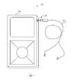
- FIG. 1illustrates generally a system employing an example interface circuit.
- FIG. 2illustrates generally a block diagram of an example interface circuit for interfacing an accessory to an electronic device processor.
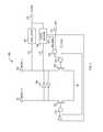
- FIG. 3illustrates generally an example reset circuit.
- FIG. 4illustrates generally an example reset state machine.
- the present subject matterincludes apparatus and methods for detecting the whether an accessory is coupled to a port of an electronic device.
- an interface circuitcan automatically configure the electronic device to disable features associated with the accessory if the accessory is not connected.
- the present subject matterincludes examples of an integrated, interface circuit and method of operation of the interface circuit.
- the interface circuitcan detect the disconnection of an audio accessory, such as an earphone, or an earphone and microphone combination, from an electronic device, such as a cell phone, mobile multimedia player or personal digital assistant, and prepare the electronic device to automatically detect a connection or re-connection of an accessory in the future.
- the interface circuitconsumes little if any energy when an accessory device is not coupled to the port.
- Examplesare provided that employ an audio jack detection (J_DET) input to automatically reset and initiate a low power state upon detecting the disconnection of an audio accessory from a port of an electronic device.
- J_DETaudio jack detection
- a methodcan debounce the J_DET input while one or more other processes or signals of the electronic device are in a low-power mode
- the methodcan initiate processing signals related to the accessory, such as audio signals received at a microphone (J-MIC) input, when the debounce of the J_DET input is complete and the presence of an audio accessory at the port is verified.
- the J_DET inputcan be debounced while the microphone processing method is not in the reset mode, such as when verifying removal of the audio accessory from the port of the electronic device.
- This method of debouncingcan accommodate noise on the J_DET input without disrupting other processes or signals related to the accessory such as processing audio information related to the accessory or providing a bias signal to the accessory.
- a methodcan provide reduced power consumption when an audio accessory is not connected to a port of the electronic device.
- a methodcan enable a processor resource, such as an oscillator or a state machine, to assist debouncing the J-DET input when an accessory is first detected at the port of the electronic device.
- a reset circuitcan enable a second method, such as a second state machine, to process information related to the accessory such as audio information related to the accessory.
- an interface circuitcan simultaneously process the audio information, and monitor and debounce the J-DET input.
- the methodcan detect noise on J_DET and prevent undesirable mode changes of the interface circuit that can otherwise occur without debouncing J_DET.
- a single integrated circuitcan monitor a port of an electronic device and process information related to the port.
- the ICcan interface to a processor of the electronic device and offload processing functions, such as, detecting an accessory coupled to the port, initializing parameters and hardware to interface to the accessory, and detecting events related to the accessory such as user initiated events that can affect the operation of the electronic device.
- the ICcan reduce power consumption of the electronic device when a user removes or decouples the accessory device from the port.
- the ICcan accommodate noisy signals introduced at the port without disrupting operation of the accessory device and can also accurately determine between a coupled state of the port and an uncoupled state of the port.
- FIG. 1illustrates generally an example system 100 employing an interface circuit circuit to interface an audio accessory 101 to an electronic device 102 .
- the electronic device 102can include a mobile electronic device including, but not limited to, a cell phone, a personal digital assistant, a personal media player, combinations thereof, or other electronic devices having an audio port.
- the accessory 102can be a set of earphones or earplugs that can include a connector 103 , such as an audio jack, that physically interfaces with an audio port of the electronic device 102 , such as an audio jack receptacle.
- the accessory 101can be a set of earphones or earplugs that include a microphone.
- the microphonecan include a switch, such as a send/end switch for initiating and ending a cell phone call, for example.
- the set of earphones or earplugsmay include only one earphone or earplug.
- FIG. 2illustrates generally a block diagram of an example interface circuit 200 for interfacing an accessory 201 to an electronic device processor 204 .
- the interface circuit 200can includes a first power supply input VIO and a second power supply input VDD, various inputs and outputs to couple the interface circuit 200 between a port 205 of the electronic device and the processor 204 of the electronic device.
- the port 205is configured to couple to with an accessory connector 206 .
- the connector 206can include terminations for one or more earphones, such as a left earphone 207 and a right earphone 208 .
- the connector 206can include a ground termination, GND.
- the connector 206can include a termination coupled to a microphone 209 of the accessory 201 .
- the connector 206can include a termination coupled to a switch 210 of the accessory. In an example, the microphone 209 and switch 210 of the accessory 201 share a termination of the connector 206 .
- the interface circuit 200can include a comparator 222 configured to receive a microphone signal at a headset microphone terminal (J_MIC), a buffer, such as a Schmitt trigger 223 , configured to receive an audio jack detection signal at an audio jack detection pin (J_DET), and a current source 224 (e.g., a 0.5 ⁇ A current source, etc.).
- the port 205can include a switch device 211 , in certain examples, operating as a normally open switch.
- the current source 224can be configured to provide a voltage at the Schmitt trigger 223 when the port 205 is empty that can be pulled to ground when an audio jack 206 is coupled with the port 205 .
- the Schmitt trigger 223can be configured to provide a detection signal to logic 214 and the processor 204 .
- the detection signalcan include a logic high signal when the port 205 is in an uncoupled state and a logic low signal when the port 205 is coupled with an audio jack connector 206 of an accessory 201 .
- the normally open configuration of the switch device 211 and the current source 224 (e.g., a 0.5 ⁇ A current source, etc.) of the interface circuit 200can be replaced with a switching device having a normally closed (NC) configuration and a current sink (e.g., a 0.5 ⁇ A current sink, etc.).
- a switching device having a normally closed (NC) configuration and a current sinke.g., a 0.5 ⁇ A current sink, etc.
- one or more other example components or systemscan be used.
- the interface circuit 200can use one or more other components to detect the audio jack 206 and to provide an indication of the detected audio jack to the processor 204 .
- the interface circuit 200can include an input J_MIC coupled to a terminal of the port 205 corresponding to the terminal of the connector 206 coupled to the microphone 210 .
- the port 205can include a switch 211 for detecting the presence of the accessory connector 206 coupled to, or mated with, the port 205 .
- the switchcan be coupled to a detection input, J_DET, of the interface circuit 200 .
- the switch 211is normally open and can close when an accessory connector 206 is coupled to the port 205 .
- the interface circuit 200can include a number of outputs DET, JPOLE, S/E, MIC, for interfacing with the processor 204 of the electronic device.
- the interface circuit 200includes an output DET indicative of whether an accessory 201 is coupled to the port 205 .
- the interface circuit 200can include an output JPOLE indicative of whether the accessory connector 206 includes a third terminal, or a third and a fourth terminal.
- the interface circuit 200can include an output S/E indicative of a state of a switch 210 of the connected accessory 201 .
- the interface circuit 200can include an output MIC for conducting audio information between the accessory 201 and an audio processor 212 of the electronic device.
- the interface circuit 200includes an internal switch 213 to reduce leakage current associated with a terminal of the accessory 201 such as the microphone terminal MIC of the connector 206 .
- the interface circuit 200can include logic 214 to receive process and generate information between the electronic device processor 204 and the accessory 201 .
- the device processor 204can include a baseband processor 220 .
- the device processor 204can include an audio coder/decoder (CODEC).
- the device processorcan include a baseband processor and an audio CODEC.
- the audio CODECcan provide a bias output, BIAS, to bias an accessory microphone 210 .
- the interface circuit 200can include a comparator 222 to compare the signal level of the J_MIC input to a reference voltage.
- the comparator 222can provide an indication of the switch action to the device processor 204 using the S/E output.
- the interface circuit 200can receive an enable input EN from the device processor 204 .
- the EN inputcan enable the interface circuit 200 .
- the EN inputcan be used to program or test the interface circuit 200 .
- the interface circuit 200can reduce the number of inputs and outputs required to interface an accessory 201 to the electronic device processor 204 , thus freeing up valuable inputs and outputs for other resources of the electronic device. In certain examples, the interface circuit 200 can offload processing that would otherwise consume processing bandwidth of the electronic device processor 204 . Thus, the interface circuit 200 can free up processing bandwidth for other processing tasks. In various examples, the interface circuit 200 can be implemented using discrete components. In some examples, the interface circuit 200 can be implemented in software. In some examples, the interface circuit 200 can be implemented using a combination of discrete components and software. In some examples, the interface circuit 200 can be implemented using a single integrated circuit chip.
- the interface circuit 200can include a reset circuit 215 for monitoring the presence of an accessory 201 coupled to the port 205 and for reducing power consumption of the interface circuit 200 when the port 205 is not coupled to an accessory 201 .
- FIG. 3illustrates generally an example reset circuit 315 that can include an active-high reset 301 output, an active-low reset 302 output, two control switches 303 , 304 , a pair of inverters 305 , and logic gates 308 , 309 , 310 .
- the reset circuit 300can include an oscillator 307 to provide a clock signal, such as an oscillator 307 to debounce an input or provide a pulse train to a state machine 306 .
- the reset circuit 300can include one or more state machines 306 to control operation of the interface circuit 200 .
- the reset outputs 301 , 302can initiate parameters or hardware to a known state.
- the reset circuit 300can include two control switches 303 , 304 and a pair of inverters 305 that assist in maintaining the logic level of the reset outputs 301 , 302 .
- the inverter pair 305can maintain the state of the reset outputs 301 , 302 in a complementary fashion until the control input to switches 303 , 304 drive the switches such that the reset outputs 301 , 302 are in complementary states.
- maintaining the reset outputs 301 , 302 in a particular statecan allow an input, such as a J_DET input 311 , to be debounced without disrupting an operating state of the interface circuit 200 .
- the J_DET input 311can be debounced if the oscillator 307 is enabled even though the signal on the J_DET input 311 flutters during the debounce routine.
- a low J_DET input 311indicates a coupled accessory device, that upon the J_DET input 311 going high, switch 303 tends to set the active high reset 301 to a high logic state.
- state machine 306can be disable to assume a low-power mode of the device.
- the J_DET input 311can return to a low logic level and switch 303 can pull the active high reset output 301 low using logic gate 310 , thus indicating the continued presence of a coupled accessory device.
- PORPower-on-Reset
- the POR signalcan indicate a state of the overall circuit including, for example, the state of the power supplies of the circuit.
- PORis at a low logic state when the power supplies are not supplying voltage within a predetermined range, such as when the supplies are off or ramping up to voltage.
- PORcan go to a high logic level. It is understood that POR can be responsive to other operating conditions in addition to power supply conditions without departing from the scope of the present subject matter.
- the reset circuit 300can be coupled to an oscillator 307 and a state machine 306 .
- the state machine 306can use a clock output 316 of the oscillator 307 to sequence the state machine 306 .
- the oscillator 307can include an enable input 317 coupled to the active low reset output 302 such that when the active low reset output 302 goes to a low logic level, the oscillator 307 can be disabled. In an example, disabling the oscillator 307 can disable the sequencing of the state machine 306 .
- the state machine 306can also include an enable input 318 coupled to the active low reset 302 . Such an enable input 318 can be used to stop the state machine 306 and optionally redirect operation of the state machine 306 to reset.
- the state machine 306can include an input coupled to the J_DET input 311 to allow the state machine 306 to debounce the signal on the J_DET input 311 .
- the state machine 306can include an output (SM_DSBL) 319 indicative of a state of the state machine 306 .
- the state machine output 319is low when the state machine 306 is active and high when the state machine 306 is inactive or disabled.
- the state machine output 319can couple to a logic gate 308 of the reset circuit 300 and can control when the reset circuit 300 sets the reset outputs 301 302 to their respective reset states.
- an interface circuit that includes the reset circuit 300can use less power than a non-reset state because state machines of the interface modules are not active and signals, such as bias signals are isolated from ports.
- a low-power mode of an interface circuitis desired when an accessory is not connected to a port of the electronic device.
- the interface circuitit is undesirable to have the interface circuit enter a reset or low power state if noise on the J_DET input 311 indicates a transition between an accessory being coupled to the port and not coupled to the port or vice versa.
- the state machine output 319can allow an interface circuit to remain enabled without interruption even though the J_DET input 311 indicates a decoupling of an accessory from a port of the electronic device.
- the state machine 306can be disabled and the interface circuit can proceed to a low power state including disabling the oscillator 307 and other hardware and processes related to the port.
- a logic gate 308NANDs the output 319 of the state machine 306 with the signal at the J_DET input 311 .
- the output 319 of the state machine 306can be high logic when the state machine 306 is disabled, and the J_DET input 311 can be high logic when the port is in a uncoupled state (e.g., an accessory is not coupled to the port).
- the NAND gate 308 outputcan be low logic when the J_DET input 311 and the output 319 of the state machine 306 are high logic. Low logic levels at an input of gate 309 turn on control switch 304 .
- the active low reset 302assumes a low logic level and disables the oscillator when a low logic level is present on the control input of gate 304 .
- the reset circuit 300When the reset circuit 300 is in a reset or low-power mode, e.g., switch 303 off and switch 304 on, a transition of the J_DET input 311 from high (e.g., uncoupled state, accessory unplugged) to low (coupled state, accessory connected) can cause the interface circuit to exit reset, or the low power mode.
- a transition of the J_DET input 311 from high (e.g., uncoupled state, accessory unplugged) to low (coupled state, accessory connected)can cause the interface circuit to exit reset, or the low power mode.
- the J_DET input 311goes to a low logic level, and the POR signal is high
- switch 303 responding to the logic high signal turning switch 303 oncan pull the active high reset signal 301 low.
- the active low reset 302On the right side of the reset circuit 300 , the active low reset 302 can assume a high logic level when several conditions are met.
- one condition in which the active low reset output 302 can assume a high logic levelis when the J_DET input 311 is at a low logic level indicating an accessory is coupled to the port.
- a low logic level at the J_DET input 311can produce a high output of logic gate 308 .
- logic gate 309can NAND the high logic level output of logic gate 308 with the high logic level of POR to turn off switch 304 , thus releasing the active low reset output 302 , for example, to be pulled high by other components.
- the reset circuit 300 of FIG. 3can operate in conjunction with the state machine 306 of an interface circuit such as the example interface circuit 200 of FIG. 2 .
- multiple state machinescan run simultaneously with the state machine 306 .
- state machinescan detect specific aspects of an accessory such as whether the accessory includes a microphone. Some state machines can detect the operation of a switch included with the accessory such as a send/end switch.
- FIG. 4illustrates generally a state machine diagram of an example reset state machine 400 .
- the reset state machine 400can detect the coupling and decoupling of an accessory with a port of an electronic device.
- the reset state machine 400can direct control of an interface circuit to a low power state when an accessory is not coupled to the port.
- the reset state machine 400can return control of the interface circuit from the low power state when an accessory is coupled to the port. In an example, the reset state machine 400 can reduce directing control of the interface circuit to the low power state when an accessory is coupled to the port and noise is present on an accessory detection input, such as the J_DET input 311 discussed above with reference to FIG. 3 .
- the reset state machine 400can enter a reset state machine (RESET_SM) state 401 from a power-on-reset (POR) state 405 when the device is first turned on.
- RESET_SM state 401can issue a command to reset other state machines of the interface circuit.
- a command to reset other state machines of the interface circuitcan disable, or suspend, the operation of the other state machines reducing power consumption of the interface circuit.
- the reset state machine 400remains in the RESET_SM state when the J_DET input is high and the oscillator is disabled.
- the reset state machine 400can transition, or jump, from the RESET_SM state 401 to a detection initialization (J_DET_INIT) state 402 when the J_DET input goes to a low logic level.
- the J_DET inputcan be an input to an interface circuit indicative of the coupled or uncoupled state of a port coupled to the interface circuit.
- the J_DET inputcan be indicative of a state of an accessory detection switch coupled to, or part of the port.
- the J_DET inputcan indicate an accessory is coupled to the port using a low logic level and can indicate the absence of an accessory coupled to the port using a high logic level.
- the transition between the RESET_SM state 401 and the J_DET_INIT state 402can happen even when noise is detected on the J_DET input.
- the J_DET_INIT state 402can initialize a counter.
- a general reset of the electronic device executing the reset state machine 400can cause execution of the reset state machine to jump to the RESET_SM state 401 .
- the reset state machine 400can transition to a count state (J_DET_COUNT) state 403 .
- the J_DET_COUNT state 403can increment the counter at a frequency determined by the oscillator as long as the J_DET input remains in the state it was in when the reset state machine 400 entered into the J_DET_INIT state 402 . If the J_DET input changes while in either the J_DET_INIT state 402 or the J_DET_COUNT state 403 , the counter is reset in the J_DET_INIT state 401 and operation continues until the counter reaches a predetermined value, such as a threshold value.
- the reset state machine 400can transition out of the J_DET_COUNT state 403 to one of two other states.
- the counteris initialized and allowed to increment to a predetermined maximum value. It is understood that other methods of initializing and incrementing the counter are possible without departing from the scope of the present subject matter including initializing the counter to a predetermined value and decrementing to a predetermined minimum value, such as zero.
- the J_DET_ACTIVE state 404can withdraw the RESET_SM command and the reset state machine 400 can remain in the J_DET_ACTIVE state 404 as long as the J_DET input remains at a low logic level.
- withdrawing the RESET_SM commandcan release operation of other state machines of the interface module.
- other state machinecan detect a particular configuration of the accessory, such as whether the accessory includes a microphone or a switch.
- Other state machinescan detect operation of a user control on the accessory. In some examples, other state machines can detect a particular accessory configuration and the operation of a user control on the accessory. In an example, other state machines can couple a bias signal to the port of the interface module, such as a microphone bias signal.
- the reset state machine 400can transition back to RESET_SM state 401 indicating the circuit has verified that the port is in an uncoupled state.
- the RESET_SM state 401can issue the RESET_SM command to allow the interface circuit to enter a low power state.
- issuing the RESET_SM commandcan isolate a bias signal from the port.
- the reset state machine 400can transition to the J_DET_INIT state to debounce the transition of the J_DET input. Note that the reset state machine 400 can debounce each transition of J_DET input to eliminate changing the state of the interface circuit should noise be responsible for creating the transition in J_DET input.
- the J_DET inputcan be debounced to ensure a true removal of an audio jack from the port and a RESET_SM command can be asserted to enter a low power state.
- a low signal on the J_DET inputcan bring the interface circuit out of a low-power mode and enable the oscillator.
- digital logiccan capture a decoupled state of the port using the J_DET input, initiate the debounce counter, and maintain the operation of the interface circuit until the debounce counter has finished.
- a methodincludes detecting a first transition of an port from a coupled state to an uncoupled state using a first signal, debouncing the uncoupled state of the port using an oscillator, maintaining operation of a second state machine while the uncoupled state of the port is debounced, and disabling the second state machine after successfully debouncing the uncoupled state of the port, wherein the disabling the second state machine includes isolating a bias signal from the port to provide a low-power operating mode.
- Example 1Athe method of Example 1 optionally includes setting a reset output after after successfully debouncing the uncoupled state of the port and disabling the second state machine using the reset output.
- Example 2the method of Examples 1 optionally include disabling the oscillator and the first state machine after successfully debouncing the uncoupled state of the port.
- Example 2Athe method of any one or more of Examples 1-2 optionally includes disabling the oscillator and the first state machine using the reset output.
- Example 3the debouncing the uncoupled state of the port of any one or more of Examples 1-2, including Example 2A, optionally includes resetting a counter, detecting if the uncoupled state of the port has changed, if the uncoupled state of the port has not changed, the method includes incrementing the counter, checking if a value of the counter has reached a threshold value, if the value of the counter has reached the threshold value, the method includes indicating a successful debounce of the uncoupled state of the port, and if the value of the counter has not reached the threshold value, the method includes jumping to the detecting if the uncoupled state of the port has changed.
- Example 4if the uncoupled state of the port has changed to the coupled state of any one or more of Examples 1-3, the method optionally includes debouncing the coupled state of the port using the oscillator.
- Example 5the method of any one or more of Examples 1-4 optionally includes detecting a second transition of the port from the uncoupled state to the coupled state using the first signal, enabling a disabled oscillator using the first signal, enabling a first state machine using the first signal, debouncing the coupled state of the port using the oscillator and the first state machine, and enabling a second state machine after successfully debouncing the coupled state of the port.
- Example 5Athe method of any one or more of Examples 1-4 optionally includes resetting the reset output using the first signal, enabling a disabled oscillator using the reset output, and enabling a first state machine using the reset output.
- Example 6the method of any one or more of Examples 1-5, including Example 5A, optionally includes disabling the oscillator and the first state machine after unsuccessfully debouncing the coupled state of the port.
- Example 7the debouncing the coupled state of the port of any one or more of Examples 1-6 optionally includes resetting a counter, detecting if the coupled state of the port has changed. If the coupled state of the audio connector has not changed, the method includes incrementing the counter and checking if a value of the counter has reached a threshold value. If the value of the counter has reached a threshold value, the method includes indicating a successful debounce of the coupled state of the port, and if the value of the counter has not reached the threshold value, the method includes jumping to the detecting if the coupled state of the first port has changed.
- Example 8if the coupled state of the port has changed to an uncoupled state in any one or more of Examples 1-7, the method optionally includes resetting the counter.
- Example 9the enabling the second state machine of any one or more of Examples 1-8 optionally includes coupling the bias signal to the port.
- Example 10the isolating a bias signal from the port of any one or more of Examples 1-9 optionally includes isolating a microphone bias signal from an audio port.
- an apparatus for providing a low power operating modeincludes an audio port configured to provide a bias signal to an accessory device during a coupled state, a first state machine configured to debounce transitions of the audio port between the coupled state and an uncoupled state, and a switch configured to isolate the bias signal from the audio port during the uncoupled state to provide the low-power operating mode.
- Example 12the apparatus of any one or more of Examples 1-11 optionally includes a a reset circuit configured to receive a signal indicative of a first transition of the audio port from the coupled state to the uncoupled state, and to maintain operation of a second state machine while the first transition is debounced.
- a reset circuitconfigured to receive a signal indicative of a first transition of the audio port from the coupled state to the uncoupled state, and to maintain operation of a second state machine while the first transition is debounced.
- Example 13the reset circuit of any one or more of Examples 1-12 is optionally configured to to receive a signal indicative of a second transition of the audio port from the uncoupled state to the coupled state, and to enable an oscillator and the first state machine to debounce the second transition.
- a portable electronic deviceincludes a port configured to couple to an accessory device, the port including a first switch configured to provide an indication of a coupled state of the port and an uncoupled state of the port, a first state machine configured to debounce transitions between the coupled state and the uncoupled state, a second state machine configured to process information received from the accessory device during the coupled state, a second switch configured to couple a bias signal to the port during the coupled state and to isolate the bias signal from the port during the uncoupled state, and a reset circuit configured to initiate the first state machine upon a transition of the port from the uncoupled state to the coupled state, and to maintain operation of the second state machine during a transition of the port from the coupled state to the uncoupled state.
- Example 15the port of any one or more of Examples 1-14 optionally includes an audio port.
- Example 16the port of any one or more of Examples 1-15 includes an audio jack receptacle.
- Example 17the reset circuit of any one or more of Examples 1-16 optionally includes first and second outputs and first and second inverters coupled between the first and second outputs, wherein the first and second inverters are configured to maintain the first and second outputs in a complementary state during the transitions of the audio port between the coupled state and the uncoupled state.
- Example 18can include, or can optionally be combined with any portion or combination of any portions of any one or more of Examples 1-17 to include, subject matter that can include means for performing any one or more of the functions of Examples 1-17, or a machine-readable medium including instructions that, when performed by a machine, cause the machine to perform any one or more of the functions of Examples 1-17.
- the terms “a” or “an”are used, as is common in patent documents, to include one or more than one, independent of any other instances or usages of “at least one” or “one or more.”
- the term “or”is used to refer to a nonexclusive or, such that “A or B” includes “A but not B,” “B but not A,” and “A and B,” unless otherwise indicated.
- Method examples described hereincan be machine or computer-implemented at least in part. Some examples can include a computer-readable medium or machine-readable medium encoded with instructions operable to configure an electronic device to perform methods as described in the above examples.
- An implementation of such methodscan include code, such as microcode, assembly language code, a higher-level language code, or the like. Such code can include computer readable instructions for performing various methods. The code may form portions of computer program products. Further, the code can be tangibly stored on one or more volatile or non-volatile tangible computer-readable media, such as during execution or at other times.
- Examples of these tangible computer-readable mediacan include, but are not limited to, hard disks, removable magnetic disks, removable optical disks (e.g., compact disks and digital video disks), magnetic cassettes, memory cards or sticks, random access memories (RAMs), read only memories (ROMs), and the like.
Landscapes
- Physics & Mathematics (AREA)
- Nonlinear Science (AREA)
- Engineering & Computer Science (AREA)
- Acoustics & Sound (AREA)
- Signal Processing (AREA)
- Circuit For Audible Band Transducer (AREA)
- Electronic Switches (AREA)
- Telephone Function (AREA)
Abstract
Description
Claims (15)
Priority Applications (1)
| Application Number | Priority Date | Filing Date | Title |
|---|---|---|---|
| US13/188,834US8817994B2 (en) | 2010-07-23 | 2011-07-22 | Audio jack reset |
Applications Claiming Priority (2)
| Application Number | Priority Date | Filing Date | Title |
|---|---|---|---|
| US36726610P | 2010-07-23 | 2010-07-23 | |
| US13/188,834US8817994B2 (en) | 2010-07-23 | 2011-07-22 | Audio jack reset |
Publications (2)
| Publication Number | Publication Date |
|---|---|
| US20120019306A1 US20120019306A1 (en) | 2012-01-26 |
| US8817994B2true US8817994B2 (en) | 2014-08-26 |
Family
ID=45493120
Family Applications (2)
| Application Number | Title | Priority Date | Filing Date |
|---|---|---|---|
| US13/188,834Active2032-07-27US8817994B2 (en) | 2010-07-23 | 2011-07-22 | Audio jack reset |
| US13/188,778Active2032-06-09US8831234B2 (en) | 2010-07-23 | 2011-07-22 | Audio jack detection and configuration |
Family Applications After (1)
| Application Number | Title | Priority Date | Filing Date |
|---|---|---|---|
| US13/188,778Active2032-06-09US8831234B2 (en) | 2010-07-23 | 2011-07-22 | Audio jack detection and configuration |
Country Status (3)
| Country | Link |
|---|---|
| US (2) | US8817994B2 (en) |
| KR (1) | KR101760354B1 (en) |
| CN (2) | CN102378087B (en) |
Cited By (4)
| Publication number | Priority date | Publication date | Assignee | Title |
|---|---|---|---|---|
| US20130129109A1 (en)* | 2011-11-22 | 2013-05-23 | Samsung Electronics Co. Ltd. | Method and apparatus for recognizing earphone in portable terminal |
| USD726223S1 (en)* | 2014-01-14 | 2015-04-07 | Cedano Guerrero | Wireless audio video jack |
| US9294857B2 (en) | 2011-07-22 | 2016-03-22 | Fairchild Semiconductor Corporation | Detection and GSM noise filtering |
| US10141902B1 (en)* | 2015-07-08 | 2018-11-27 | Marvell World Trade Ltd. | Apparatus for and method of generating output signal based on detected load resistance value |
Families Citing this family (35)
| Publication number | Priority date | Publication date | Assignee | Title |
|---|---|---|---|---|
| US8244927B2 (en) | 2009-10-27 | 2012-08-14 | Fairchild Semiconductor Corporation | Method of detecting accessories on an audio jack |
| US8817994B2 (en) | 2010-07-23 | 2014-08-26 | Fairchild Semiconductor Corporation | Audio jack reset |
| US9229833B2 (en) | 2011-01-28 | 2016-01-05 | Fairchild Semiconductor Corporation | Successive approximation resistor detection |
| WO2013032822A2 (en) | 2011-08-26 | 2013-03-07 | Dts Llc | Audio adjustment system |
| US9678560B2 (en)* | 2011-11-28 | 2017-06-13 | Intel Corporation | Methods and apparatuses to wake computer systems from sleep states |
| US8948685B2 (en)* | 2012-01-06 | 2015-02-03 | Blackberry Limited | Mobile wireless communications device using wired headset as an antenna and related methods |
| CN102707188B (en)* | 2012-06-04 | 2014-08-13 | 昆山嘉华电子有限公司 | Audio connector testing device |
| CN103475965B (en)* | 2012-06-07 | 2018-07-27 | 深圳富泰宏精密工业有限公司 | Electronic device |
| US8909173B2 (en)* | 2012-06-29 | 2014-12-09 | Motorola Solutions, Inc. | Method and apparatus for operating accessory interface functions over a single signal |
| US9060228B2 (en)* | 2012-08-03 | 2015-06-16 | Fairchild Semiconductor Corporation | Accessory detection circuit with improved functionality |
| GB2509316B (en)* | 2012-12-27 | 2015-02-25 | Wolfson Microelectronics Plc | Detection circuit |
| US9223388B2 (en)* | 2013-01-29 | 2015-12-29 | Hewlett Packard Enterprise Development Lp | Power state transition saving session information |
| KR102086615B1 (en)* | 2013-02-13 | 2020-03-10 | 온세미컨덕터코리아 주식회사 | Jack detector, detecting device, and detecting method |
| US9681241B2 (en)* | 2013-02-26 | 2017-06-13 | Blackberry Limited | Apparatus, systems and methods for detecting insertion or removal of an audio accessory from an electronic device |
| CN104599672B (en)* | 2013-10-31 | 2018-04-03 | 瑞昱半导体股份有限公司 | There are the audio codec and audio grafting detection method of audio grafting detectability |
| US9584893B2 (en)* | 2014-01-20 | 2017-02-28 | Fairchild Semiconductor Corporation | Apparatus and method for recovering from partial insertion of an audio jack |
| US9794708B2 (en)* | 2014-01-20 | 2017-10-17 | Fairchild Semiconductor Corporation | Apparatus and method for detecting insertion anomaly of an audio jack |
| US9674598B2 (en) | 2014-04-15 | 2017-06-06 | Fairchild Semiconductor Corporation | Audio accessory communication with active noise cancellation |
| US9793658B2 (en)* | 2014-06-01 | 2017-10-17 | Apple Inc. | Reuse of plug detection contacts to reduce crosstalk |
| EP2961196B1 (en)* | 2014-06-26 | 2016-09-21 | ams AG | Host interface, accessory interface and method for managing a connection between a host interface and an accessory device |
| US9525928B2 (en)* | 2014-10-01 | 2016-12-20 | Michael G. Lannon | Exercise system with headphone detection circuitry |
| JP6316728B2 (en)* | 2014-10-22 | 2018-04-25 | 京セラ株式会社 | Electronic device, earphone, and electronic device system |
| JP6352157B2 (en)* | 2014-11-14 | 2018-07-04 | 株式会社オーディオテクニカ | Microphone |
| US9813816B2 (en)* | 2015-01-26 | 2017-11-07 | Realtek Semiconductor Corp. | Audio plug detection structure in audio jack corresponding to audio plug and method thereof |
| CN106154105B (en)* | 2015-02-02 | 2019-10-25 | 瑞昱半导体股份有限公司 | Audio plug detection structure and method thereof |
| US9743188B2 (en)* | 2015-03-11 | 2017-08-22 | Texas Instruments Incorporated | Audio plug type detection |
| US9785487B1 (en)* | 2015-05-12 | 2017-10-10 | Google Inc. | Managing device functions based on physical interaction with device modules |
| CN106303822B (en)* | 2015-06-25 | 2021-06-08 | 朗新科技集团股份有限公司 | Mobile phone audio interface communication equipment |
| DE102015013572B4 (en)* | 2015-10-14 | 2017-08-24 | CSS MicroSystems GmbH | Universal connection system for sensors and methods for detecting sensors |
| KR102393364B1 (en)* | 2015-10-29 | 2022-05-03 | 삼성전자주식회사 | Method for controlling audio signal and electronic device supporting the same |
| TWI582686B (en)* | 2016-03-28 | 2017-05-11 | 宏碁股份有限公司 | Electronic device, detection device and method for setting output of headset |
| US10312902B2 (en)* | 2016-10-28 | 2019-06-04 | Analog Devices Global | Low-area, low-power, power-on reset circuit |
| TWI659657B (en)* | 2017-09-26 | 2019-05-11 | 瑞昱半導體股份有限公司 | Detecting circuit and associated detecting method |
| DE102018126327A1 (en) | 2017-10-23 | 2019-04-25 | Maxim Integrated Products, Inc. | Systems and methods for accessory and impedance detection |
| US11720559B2 (en)* | 2020-06-02 | 2023-08-08 | Salesforce.Com, Inc. | Bridging textual and tabular data for cross domain text-to-query language semantic parsing with a pre-trained transformer language encoder and anchor text |
Citations (36)
| Publication number | Priority date | Publication date | Assignee | Title |
|---|---|---|---|---|
| US5754552A (en) | 1995-07-12 | 1998-05-19 | Compaq Computer Corporation | Automatic communication protocol detection system and method for network systems |
| US6301344B1 (en) | 1997-11-05 | 2001-10-09 | Protel, Inc. | Intelligent public telephone system and method |
| CN1441353A (en) | 2002-02-28 | 2003-09-10 | 德克萨斯仪器股份有限公司 | Bus monitor controller for reinforced universal serial bus |
| US6650635B1 (en) | 1996-08-23 | 2003-11-18 | Hewlett-Packard Development Company, L.P. | Network telephone communication |
| US20050201568A1 (en)* | 2004-03-11 | 2005-09-15 | Texas Instruments Incorporated | Headset Detector in a Device Generating Audio Signals |
| CN1708023A (en) | 2004-06-08 | 2005-12-14 | 伯斯有限公司 | Managing an audio network |
| US7053598B2 (en) | 2002-12-04 | 2006-05-30 | C-Media Electronics, Inc. | Structure for detecting plug/unplug status of phone-jacks by single bit generated by a resistor network |
| US20060147059A1 (en) | 2004-12-30 | 2006-07-06 | Inventec Appliances Corporation | Smart volume adjusting method for a multi-media system |
| US20070133828A1 (en) | 2005-12-14 | 2007-06-14 | Ajaykumar Kanji | Audio input-output module, plug-in detection module and methods for use therewith |
| CN101069410A (en) | 2004-10-25 | 2007-11-07 | 诺基亚公司 | Detection, identification and operation of peripherals connected to electronic equipment via audio/video plugs |
| US20080140902A1 (en) | 2006-12-08 | 2008-06-12 | Karl Townsend | Multi-interfaced accessory device for use with host computing systems |
| US20080150512A1 (en) | 2006-12-25 | 2008-06-26 | Nikon Corporation | Electronic device |
| US20080247241A1 (en) | 2007-04-05 | 2008-10-09 | Hao Thai Nguyen | Sensing in non-volatile storage using pulldown to regulated source voltage to remove system noise |
| US20080298607A1 (en) | 2007-05-30 | 2008-12-04 | Fortemedia, Inc. | Audio interface device and method |
| CN101426035A (en) | 2007-10-31 | 2009-05-06 | 索尼爱立信移动通讯有限公司 | Additional pins on a usb connector |
| CN101425048A (en) | 2007-10-31 | 2009-05-06 | 索尼爱立信移动通讯有限公司 | Electronic device utilizing impedance and/or resistance identification to identify an accessory device |
| US20090180630A1 (en)* | 2008-01-14 | 2009-07-16 | Sander Wendell B | Electronic device circuitry for communicating with accessories |
| US7565458B2 (en) | 2003-12-12 | 2009-07-21 | Sony Ericsson Mobile Communications Ab | Cell phone accessory identification algorithm by generating and measuring a voltage pulse through a pin interface |
| US20090198841A1 (en) | 2008-02-06 | 2009-08-06 | Matsushita Electric Industrial Co., Ltd. | Interface detecting circuit and interface detecting method |
| CN101729958A (en) | 2008-10-24 | 2010-06-09 | 深圳富泰宏精密工业有限公司 | Audio frequency output device |
| US20100173673A1 (en) | 2008-09-08 | 2010-07-08 | Apple Inc. | Cross-transport authentication |
| US20100199112A1 (en) | 2009-01-30 | 2010-08-05 | Kabushiki Kaisha Toshiba | Information processing apparatus and power supply control method |
| US7916875B2 (en)* | 2005-12-14 | 2011-03-29 | Integrated Device Technology, Inc. | Audio input-output module, plug-in device detection module and methods for use therewith |
| US20110085673A1 (en) | 2009-10-14 | 2011-04-14 | Samsung Electronics Co. Ltd. | Circuit apparatus for recognizing earphone in mobile terminal |
| US20110099300A1 (en) | 2009-10-27 | 2011-04-28 | Fairchild Semiconductor Corporation | Camera shutter control through a usb port or audio/video port |
| US20110099298A1 (en) | 2009-10-27 | 2011-04-28 | Fairchild Semiconductor Corporation | Method of detecting accessories on an audio jack |
| KR20110046361A (en) | 2009-10-27 | 2011-05-04 | 페어차일드 세미컨덕터 코포레이션 | How to Detect Attachments with Audio Jacks |
| US20110199123A1 (en) | 2010-02-12 | 2011-08-18 | Fairchild Semiconductor Corporation | Multiple detection circuit for accessory jacks |
| US8064613B1 (en) | 2008-03-03 | 2011-11-22 | Maxim Integrated Products, Inc. | Electret microphone detection using a current source |
| US20120019309A1 (en) | 2010-07-23 | 2012-01-26 | Turner John R | Audio jack detection and configuration |
| US20120057078A1 (en) | 2010-03-04 | 2012-03-08 | Lawrence Fincham | Electronic adapter unit for selectively modifying audio or video data for use with an output device |
| US20120198183A1 (en) | 2011-01-28 | 2012-08-02 | Randall Wetzel | Successive approximation resistor detection |
| US20120200172A1 (en) | 2011-02-09 | 2012-08-09 | Apple Inc. | Audio accessory type detection and connector pin signal assignment |
| US20120237051A1 (en) | 2011-03-15 | 2012-09-20 | Samsung Electronics Co. Ltd. | Earphone system for mobile devices |
| CN102892059A (en) | 2011-07-22 | 2013-01-23 | 飞兆半导体公司 | Detection and GSM noise filtering |
| US8467828B2 (en) | 2007-01-05 | 2013-06-18 | Apple Inc. | Audio I O headset plug and plug detection circuitry |
Family Cites Families (8)
| Publication number | Priority date | Publication date | Assignee | Title |
|---|---|---|---|---|
| CN1728082A (en) | 2005-07-29 | 2006-02-01 | 上海贝豪通讯电子有限公司 | Method for raising versatility of earphone interface |
| CN1859813B (en) | 2005-09-28 | 2010-10-27 | 华为技术有限公司 | A method for switching signals between internal and external microphones |
| CN101179871B (en) | 2006-11-10 | 2012-09-05 | 鸿富锦精密工业(深圳)有限公司 | Earphone and audio play device |
| KR20090055359A (en)* | 2007-11-28 | 2009-06-02 | 삼성전자주식회사 | 4 pole earphone and 5 pole earphone compatible circuit and method and mobile terminal using the same |
| CN101453510A (en) | 2007-12-05 | 2009-06-10 | 德信智能手机技术(北京)有限公司 | Earphone recognition apparatus and method for mobile communication terminal |
| US8059838B2 (en) | 2008-05-15 | 2011-11-15 | Fortemedia, Inc. | Interfacing circuit for a removable microphone |
| CN101771737A (en) | 2009-01-05 | 2010-07-07 | 深圳富泰宏精密工业有限公司 | Electronic device |
| US8150046B2 (en)* | 2009-02-26 | 2012-04-03 | Research In Motion Limited | Audio jack for a portable electronic device |
- 2011
- 2011-07-22USUS13/188,834patent/US8817994B2/enactiveActive
- 2011-07-22USUS13/188,778patent/US8831234B2/enactiveActive
- 2011-07-25KRKR1020110073717Apatent/KR101760354B1/enactiveActive
- 2011-07-25CNCN201110209512.5Apatent/CN102378087B/enactiveActive
- 2011-07-25CNCN201110209513.XApatent/CN102404666B/enactiveActive
Patent Citations (62)
| Publication number | Priority date | Publication date | Assignee | Title |
|---|---|---|---|---|
| US5754552A (en) | 1995-07-12 | 1998-05-19 | Compaq Computer Corporation | Automatic communication protocol detection system and method for network systems |
| US6650635B1 (en) | 1996-08-23 | 2003-11-18 | Hewlett-Packard Development Company, L.P. | Network telephone communication |
| US6301344B1 (en) | 1997-11-05 | 2001-10-09 | Protel, Inc. | Intelligent public telephone system and method |
| CN1441353A (en) | 2002-02-28 | 2003-09-10 | 德克萨斯仪器股份有限公司 | Bus monitor controller for reinforced universal serial bus |
| US7053598B2 (en) | 2002-12-04 | 2006-05-30 | C-Media Electronics, Inc. | Structure for detecting plug/unplug status of phone-jacks by single bit generated by a resistor network |
| US7565458B2 (en) | 2003-12-12 | 2009-07-21 | Sony Ericsson Mobile Communications Ab | Cell phone accessory identification algorithm by generating and measuring a voltage pulse through a pin interface |
| US20050201568A1 (en)* | 2004-03-11 | 2005-09-15 | Texas Instruments Incorporated | Headset Detector in a Device Generating Audio Signals |
| CN1708023A (en) | 2004-06-08 | 2005-12-14 | 伯斯有限公司 | Managing an audio network |
| CN101069410A (en) | 2004-10-25 | 2007-11-07 | 诺基亚公司 | Detection, identification and operation of peripherals connected to electronic equipment via audio/video plugs |
| US20080318629A1 (en) | 2004-10-25 | 2008-12-25 | Nokia Corporation | Detection, Identification and Operation of Pheripherals Connected Via an Audio/Video-Plug to an Electronic Device |
| US20060147059A1 (en) | 2004-12-30 | 2006-07-06 | Inventec Appliances Corporation | Smart volume adjusting method for a multi-media system |
| US20070133828A1 (en) | 2005-12-14 | 2007-06-14 | Ajaykumar Kanji | Audio input-output module, plug-in detection module and methods for use therewith |
| US7916875B2 (en)* | 2005-12-14 | 2011-03-29 | Integrated Device Technology, Inc. | Audio input-output module, plug-in device detection module and methods for use therewith |
| US20080140902A1 (en) | 2006-12-08 | 2008-06-12 | Karl Townsend | Multi-interfaced accessory device for use with host computing systems |
| US20080150512A1 (en) | 2006-12-25 | 2008-06-26 | Nikon Corporation | Electronic device |
| US8467828B2 (en) | 2007-01-05 | 2013-06-18 | Apple Inc. | Audio I O headset plug and plug detection circuitry |
| US20080247241A1 (en) | 2007-04-05 | 2008-10-09 | Hao Thai Nguyen | Sensing in non-volatile storage using pulldown to regulated source voltage to remove system noise |
| US20080298607A1 (en) | 2007-05-30 | 2008-12-04 | Fortemedia, Inc. | Audio interface device and method |
| CN101425048A (en) | 2007-10-31 | 2009-05-06 | 索尼爱立信移动通讯有限公司 | Electronic device utilizing impedance and/or resistance identification to identify an accessory device |
| CN101426035A (en) | 2007-10-31 | 2009-05-06 | 索尼爱立信移动通讯有限公司 | Additional pins on a usb connector |
| US20090180630A1 (en)* | 2008-01-14 | 2009-07-16 | Sander Wendell B | Electronic device circuitry for communicating with accessories |
| US7869608B2 (en) | 2008-01-14 | 2011-01-11 | Apple Inc. | Electronic device accessory |
| US20090198841A1 (en) | 2008-02-06 | 2009-08-06 | Matsushita Electric Industrial Co., Ltd. | Interface detecting circuit and interface detecting method |
| US8064613B1 (en) | 2008-03-03 | 2011-11-22 | Maxim Integrated Products, Inc. | Electret microphone detection using a current source |
| US20100173673A1 (en) | 2008-09-08 | 2010-07-08 | Apple Inc. | Cross-transport authentication |
| CN101729958A (en) | 2008-10-24 | 2010-06-09 | 深圳富泰宏精密工业有限公司 | Audio frequency output device |
| US20100199112A1 (en) | 2009-01-30 | 2010-08-05 | Kabushiki Kaisha Toshiba | Information processing apparatus and power supply control method |
| US20110085673A1 (en) | 2009-10-14 | 2011-04-14 | Samsung Electronics Co. Ltd. | Circuit apparatus for recognizing earphone in mobile terminal |
| US20110099300A1 (en) | 2009-10-27 | 2011-04-28 | Fairchild Semiconductor Corporation | Camera shutter control through a usb port or audio/video port |
| US20110099298A1 (en) | 2009-10-27 | 2011-04-28 | Fairchild Semiconductor Corporation | Method of detecting accessories on an audio jack |
| KR20110046361A (en) | 2009-10-27 | 2011-05-04 | 페어차일드 세미컨덕터 코포레이션 | How to Detect Attachments with Audio Jacks |
| US20140025845A1 (en) | 2009-10-27 | 2014-01-23 | Fairchild Semiconductor Corporation | Detecting accessories on an audio or video jack |
| US8230126B2 (en) | 2009-10-27 | 2012-07-24 | Fairchild Semiconductor Corporation | Camera shutter control through a USB port or audio/video port |
| US8489782B2 (en) | 2009-10-27 | 2013-07-16 | Fairchild Semiconductor Corporation | Detecting accessories on an audio or video jack |
| US20120326736A1 (en) | 2009-10-27 | 2012-12-27 | Fairchild Semiconductor Corporation | Detecting accessories on an audio or video jack |
| US8244927B2 (en) | 2009-10-27 | 2012-08-14 | Fairchild Semiconductor Corporation | Method of detecting accessories on an audio jack |
| US20110199123A1 (en) | 2010-02-12 | 2011-08-18 | Fairchild Semiconductor Corporation | Multiple detection circuit for accessory jacks |
| US8193834B2 (en) | 2010-02-12 | 2012-06-05 | Fairchild Semiconductor Corporation | Multiple detection circuit for accessory jacks |
| CN102193047A (en) | 2010-02-12 | 2011-09-21 | 飞兆半导体公司 | Multiple detection circuit for accessory jacks |
| US20120057078A1 (en) | 2010-03-04 | 2012-03-08 | Lawrence Fincham | Electronic adapter unit for selectively modifying audio or video data for use with an output device |
| CN102378087A (en) | 2010-07-23 | 2012-03-14 | 飞兆半导体公司 | Audio jack reset |
| US20120019309A1 (en) | 2010-07-23 | 2012-01-26 | Turner John R | Audio jack detection and configuration |
| KR20120015265A (en) | 2010-07-23 | 2012-02-21 | 페어차일드 세미컨덕터 코포레이션 | Detect and Configure Audio Jacks |
| US20120198183A1 (en) | 2011-01-28 | 2012-08-02 | Randall Wetzel | Successive approximation resistor detection |
| US20120200172A1 (en) | 2011-02-09 | 2012-08-09 | Apple Inc. | Audio accessory type detection and connector pin signal assignment |
| US20120237051A1 (en) | 2011-03-15 | 2012-09-20 | Samsung Electronics Co. Ltd. | Earphone system for mobile devices |
| US20130020882A1 (en) | 2011-07-22 | 2013-01-24 | Prentice Seth M | Mic/gnd detection and automatic switch |
| KR20130011990A (en) | 2011-07-22 | 2013-01-30 | 페어차일드 세미컨덕터 코포레이션 | Mic/gnd detection and automatic switch |
| US20130021046A1 (en) | 2011-07-22 | 2013-01-24 | Fairchild Semiconductor Corporation | Audio jack detection circuit |
| CN102892068A (en) | 2011-07-22 | 2013-01-23 | 飞兆半导体公司 | MIC/GND detection and automatic switch |
| KR20130011989A (en) | 2011-07-22 | 2013-01-30 | 페어차일드 세미컨덕터 코포레이션 | Detection and gsm noise filtering |
| KR20130011988A (en) | 2011-07-22 | 2013-01-30 | 페어차일드 세미컨덕터 코포레이션 | Mic audio noise filtering |
| KR20130011991A (en) | 2011-07-22 | 2013-01-30 | 페어차일드 세미컨덕터 코포레이션 | Audio jack detection circuit |
| US20130021041A1 (en) | 2011-07-22 | 2013-01-24 | Fairchild Semiconductor Corporation | Detection and gsm noise filtering |
| US20130034242A1 (en) | 2011-07-22 | 2013-02-07 | Fairchild Semiconductor Corporation | Mic audio noise filtering |
| TW201312874A (en) | 2011-07-22 | 2013-03-16 | Fairchild Semiconductor | Audio jack detection circuit |
| TW201312873A (en) | 2011-07-22 | 2013-03-16 | Fairchild Semiconductor | MIC/GND detection and automatic switch |
| TW201314674A (en) | 2011-07-22 | 2013-04-01 | Fairchild Semiconductor | Microphone audio noise filtering |
| TW201316704A (en) | 2011-07-22 | 2013-04-16 | Fairchild Semiconductor | Detection and global mobile communication system noise filtering |
| CN102892061A (en) | 2011-07-22 | 2013-01-23 | 飞兆半导体公司 | Circuit and method for MIC audio noise filtering |
| CN102892067A (en) | 2011-07-22 | 2013-01-23 | 飞兆半导体公司 | System and method for audio jack detection |
| CN102892059A (en) | 2011-07-22 | 2013-01-23 | 飞兆半导体公司 | Detection and GSM noise filtering |
Non-Patent Citations (42)
| Title |
|---|
| "Autonomous Audio Headset Switch", Texas Instruments TS3A225E, [Online]. Retrieved from the Internet: , (Nov. 2011), 11 pgs. |
| "Autonomous Audio Headset Switch", Texas Instruments TS3A225E, [Online]. Retrieved from the Internet: <URL: http://www.ti.com/lit/ds/scds329/scds329.pdf>, (Nov. 2011), 11 pgs. |
| "USB OTG Mechanical Presentation", [Online] Retrieved from the Internet on Jun. 3, 2011 http://www.usb.org/developers/onthego/london/OTG-mechanical.pdf, (Feb. 26, 2002), 27 pgs. |
| "USB Remote Cable", [Online]. Retrieved from the Internet: , (Jun. 9, 2009), 4 pgs. |
| "USB Remote Cable", [Online]. Retrieved from the Internet: <URL: http://chdk.wikia.com/wiki/USB—Remote—Cable>, (Jun. 9, 2009), 4 pgs. |
| Chinese Application Serial No. 201010526298.1, Office Action mailed Apr. 3, 2014, 11 pgs. |
| Chinese Application Serial No. 201010526298.1, Office Action mailed Sep. 4, 2013, 10 pgs. |
| Chinese Application Serial No. 201010526298.1, Response filed Jan. 14, 2014 to Office Action mailed Sep. 4, 2013, 16 pgs. |
| Chinese Application Serial No. 201110038132.X, Office Action mailed Aug. 9, 2013, 11 pgs. |
| Chinese Application Serial No. 201110038132.X, Response filed Dec. 23, 2013 to Office Action mailed Aug. 9, 2013, 8 pgs. |
| Chinese Application Serial No. 201110209512.5, Office Action mailed Sep. 4, 2013, 5 pgs. |
| Chinese Application Serial No. 201110209512.5, Response filed Jan. 20, 2014 to Office Action mailed Sep. 4, 2013, 49 pgs. |
| Chinese Application Serial No. 201110209513.X, Office Action mailed Feb. 8, 2014, 9 pgs. |
| Chinese Application Serial No. 201220044818.X, Notification to Make Rectification mailed Jul. 17, 2012, 3 pg. |
| Korean Application Serial No. 10-2011-0073717, Amendment Filed Aug. 19, 2011, 4 pgs. |
| Mehta, Arpit, "Keep Power Consumption in Check with Low-Power Comparators that Autosense Plugged-In Accessories", [Online]. Retrieved from the Internet: , (Feb. 27, 2009), 6 pgs. |
| Mehta, Arpit, "Keep Power Consumption in Check with Low-Power Comparators that Autosense Plugged-In Accessories", [Online]. Retrieved from the Internet: <URL: http://www.maxim-ic.com/appnotes.cfm/an—pk/4327>, (Feb. 27, 2009), 6 pgs. |
| U.S. Appl. No. 12/606,562 , Response filed Jan. 3, 2012 to Final Office Action mailed Oct. 28, 2011, 7 pgs. |
| U.S. Appl. No. 12/606,562 , Response filed Sep. 13, 2011 to Non Final Office Action mailed Jun. 22, 2011, 9 pgs. |
| U.S. Appl. No. 12/606,562, Final Office Action mailed Oct. 28, 2011, 10 pgs. |
| U.S. Appl. No. 12/606,562, Non Final Office Action mailed Jun. 22, 2011, 9 pgs. |
| U.S. Appl. No. 12/606,562, Notice of Allowance Mailed Jan. 27, 2012, 7 pgs. |
| U.S. Appl. No. 12/606,562, Response to Rule 312 Communication mailed Jul. 2, 2012, 2 pgs. |
| U.S. Appl. No. 12/606,562, Response to Rule 312 Communication mailed May 29, 2012, 1 pgs. |
| U.S. Appl. No. 12/606,582, Final Office Action mailed Dec. 8, 2011, 10 pgs. |
| U.S. Appl. No. 12/606,582, Non Final Office Action mailed Jul. 14, 2011, 8 pgs. |
| U.S. Appl. No. 12/606,582, Notice of Allowance mailed Apr. 12, 2012, 8 pgs. |
| U.S. Appl. No. 12/606,582, Response filed Mar. 6, 2012 to Final Office Action mailed Dec. 8, 2011, 10 pgs. |
| U.S. Appl. No. 12/606,582, Response filed Sep. 28, 2011 to Non Final Office Action mailed Jul. 14, 2011, 10 pgs. |
| U.S. Appl. No. 12/705,183, Notice of Allowance mailed Feb. 9, 2012, 8 pgs. |
| U.S. Appl. No. 13/188,778, filed Jul. 22, 2011, Audio Jack Detection and Configuration. |
| U.S. Appl. No. 13/188,778, Final Office Action mailed Mar. 6, 2014, 15 pgs. |
| U.S. Appl. No. 13/188,778, Non Final Office Action mailed Sep. 10, 2013, 18 pgs. |
| U.S. Appl. No. 13/188,778, Response filed Feb. 10, 2014 to Non Final Office Action mailed Sep. 10, 2013, 14 pgs. |
| U.S. Appl. No. 13/189,480, filed Jul. 22, 2011, MIC/GND Detection and Automatic Switch. |
| U.S. Appl. No. 13/189,480, Non Final Office Action mailed Mar. 14, 2014, 14 pgs. |
| U.S. Appl. No. 13/569,746, filed Aug. 8, 2012, Detection and GSM Noise Filtering. |
| U.S. Appl. No. 13/569,869, filed Aug. 8, 2012, Audio Jack Detection Circuit. |
| U.S. Appl. No. 13/584,465 , Response filed Jan. 9, 2013 to Non Final Office Action mailed Nov. 15, 2012, 8 pgs. |
| U.S. Appl. No. 13/584,465, filed Aug. 13, 2012, Detecting Accessories on an Audio or Video Jack. |
| U.S. Appl. No. 13/584,465, Non Final Office Action mailed Nov. 15, 2012, 8 pgs. |
| U.S. Appl. No. 13/584,465, Notice of Allowance mailed Mar. 18, 2013, 7 pgs. |
Cited By (8)
| Publication number | Priority date | Publication date | Assignee | Title |
|---|---|---|---|---|
| US9294857B2 (en) | 2011-07-22 | 2016-03-22 | Fairchild Semiconductor Corporation | Detection and GSM noise filtering |
| US9432786B2 (en) | 2011-07-22 | 2016-08-30 | Fairchild Semiconductor Corporation | MIC audio noise filtering |
| US9497559B2 (en) | 2011-07-22 | 2016-11-15 | Fairchild Semiconductor Corporation | MIC/GND detection and automatic switch |
| US9591421B2 (en) | 2011-07-22 | 2017-03-07 | Fairchild Semiconductor Corporation | Audio jack detection circuit |
| US20130129109A1 (en)* | 2011-11-22 | 2013-05-23 | Samsung Electronics Co. Ltd. | Method and apparatus for recognizing earphone in portable terminal |
| US9282391B2 (en)* | 2011-11-22 | 2016-03-08 | Samsung Electronics Co., Ltd. | Method and apparatus for recognizing earphone in portable terminal |
| USD726223S1 (en)* | 2014-01-14 | 2015-04-07 | Cedano Guerrero | Wireless audio video jack |
| US10141902B1 (en)* | 2015-07-08 | 2018-11-27 | Marvell World Trade Ltd. | Apparatus for and method of generating output signal based on detected load resistance value |
Also Published As
| Publication number | Publication date |
|---|---|
| CN102404666A (en) | 2012-04-04 |
| US20120019309A1 (en) | 2012-01-26 |
| US20120019306A1 (en) | 2012-01-26 |
| CN102404666B (en) | 2015-05-13 |
| KR101760354B1 (en) | 2017-07-21 |
| CN102378087B (en) | 2014-06-11 |
| KR20120015265A (en) | 2012-02-21 |
| US8831234B2 (en) | 2014-09-09 |
| CN102378087A (en) | 2012-03-14 |
Similar Documents
| Publication | Publication Date | Title |
|---|---|---|
| US8817994B2 (en) | Audio jack reset | |
| CN110096253B (en) | Device wake-up and speaker verification with identical audio input | |
| US9141401B2 (en) | Method for switching system state and portable terminal | |
| JP5635628B2 (en) | Power management method and apparatus for network access module | |
| US8754612B2 (en) | Battery gas gauge reset mechanism | |
| CN104516296B (en) | A kind of awakening method and peripheral module of the micro controller system based on peripheral module | |
| KR20160077154A (en) | Intelligent ancillary electronic device | |
| US8829932B2 (en) | No pin test mode | |
| CN110622143A (en) | System and method for reducing memory power consumption via device-specific customization of DDR interface parameters | |
| US8989660B2 (en) | Multiple hardware interrupt functionality on near-field communication (NFC) | |
| EP2765824A1 (en) | Mobile terminal boot control method and mobile terminal | |
| US20120117280A1 (en) | Detection of USB Attachment | |
| KR20000069050A (en) | Method and apparatus for docking and undocking a notebook computer | |
| US20180373670A1 (en) | State detection mechanism | |
| CN103376876B (en) | Audio Interface Unit and method for managing power supply thereof | |
| US20180034749A1 (en) | System and method for distributing and replaying trigger packets via a variable latency bus interconnect | |
| US20140180457A1 (en) | Electronic device to align audio flow | |
| GB2572065A (en) | Methods and apparatus relating to data transfer over a USB connector | |
| US9713090B2 (en) | Low-power communication apparatus and associated methods | |
| CN113316057B (en) | Headphones, methods, devices and electronic equipment for reducing power consumption | |
| CN108966079A (en) | control method and system of audio device | |
| CN114924639B (en) | Electronic device and method for waking up micro control unit | |
| US9886412B2 (en) | Communication apparatus having an oscillator that is disabled based on idle state detection of a communication link and associated methods | |
| CN112764514A (en) | Screen unlocking method and device, storage medium and mobile terminal | |
| CN104506982A (en) | Timing type microphone meeting system and application thereof |
Legal Events
| Date | Code | Title | Description |
|---|---|---|---|
| FEPP | Fee payment procedure | Free format text:PAYOR NUMBER ASSIGNED (ORIGINAL EVENT CODE: ASPN); ENTITY STATUS OF PATENT OWNER: LARGE ENTITY | |
| FEPP | Fee payment procedure | Free format text:PAYOR NUMBER ASSIGNED (ORIGINAL EVENT CODE: ASPN); ENTITY STATUS OF PATENT OWNER: LARGE ENTITY | |
| FEPP | Fee payment procedure | Free format text:PAYER NUMBER DE-ASSIGNED (ORIGINAL EVENT CODE: RMPN); ENTITY STATUS OF PATENT OWNER: LARGE ENTITY | |
| AS | Assignment | Owner name:FAIRCHILD SEMICONDUCTOR CORPORATION, CALIFORNIA Free format text:ASSIGNMENT OF ASSIGNORS INTEREST;ASSIGNORS:TURNER, JOHN R.;PRENTICE, SETH M.;SIGNING DATES FROM 20110727 TO 20110728;REEL/FRAME:032053/0960 | |
| STCF | Information on status: patent grant | Free format text:PATENTED CASE | |
| AS | Assignment | Owner name:DEUTSCHE BANK AG NEW YORK BRANCH, AS COLLATERAL AGENT, NEW YORK Free format text:PATENT SECURITY AGREEMENT;ASSIGNOR:FAIRCHILD SEMICONDUCTOR CORPORATION;REEL/FRAME:040075/0644 Effective date:20160916 Owner name:DEUTSCHE BANK AG NEW YORK BRANCH, AS COLLATERAL AG Free format text:PATENT SECURITY AGREEMENT;ASSIGNOR:FAIRCHILD SEMICONDUCTOR CORPORATION;REEL/FRAME:040075/0644 Effective date:20160916 | |
| MAFP | Maintenance fee payment | Free format text:PAYMENT OF MAINTENANCE FEE, 4TH YEAR, LARGE ENTITY (ORIGINAL EVENT CODE: M1551) Year of fee payment:4 | |
| AS | Assignment | Owner name:SEMICONDUCTOR COMPONENTS INDUSTRIES, LLC, ARIZONA Free format text:ASSIGNMENT OF ASSIGNORS INTEREST;ASSIGNOR:FAIRCHILD SEMICONDUCTOR CORPORATION;REEL/FRAME:057694/0374 Effective date:20210722 | |
| AS | Assignment | Owner name:FAIRCHILD SEMICONDUCTOR CORPORATION, ARIZONA Free format text:RELEASE BY SECURED PARTY;ASSIGNOR:DEUTSCHE BANK AG NEW YORK BRANCH;REEL/FRAME:057969/0206 Effective date:20211027 | |
| AS | Assignment | Owner name:DEUTSCHE BANK AG NEW YORK BRANCH, AS COLLATERAL AGENT, NEW YORK Free format text:SECURITY INTEREST;ASSIGNOR:SEMICONDUCTOR COMPONENTS INDUSTRIES, LLC;REEL/FRAME:058871/0799 Effective date:20211028 | |
| MAFP | Maintenance fee payment | Free format text:PAYMENT OF MAINTENANCE FEE, 8TH YEAR, LARGE ENTITY (ORIGINAL EVENT CODE: M1552); ENTITY STATUS OF PATENT OWNER: LARGE ENTITY Year of fee payment:8 | |
| AS | Assignment | Owner name:FAIRCHILD SEMICONDUCTOR CORPORATION, ARIZONA Free format text:RELEASE OF SECURITY INTEREST IN PATENTS RECORDED AT REEL 040075, FRAME 0644;ASSIGNOR:DEUTSCHE BANK AG NEW YORK BRANCH, AS COLLATERAL AGENT;REEL/FRAME:064070/0536 Effective date:20230622 Owner name:SEMICONDUCTOR COMPONENTS INDUSTRIES, LLC, ARIZONA Free format text:RELEASE OF SECURITY INTEREST IN PATENTS RECORDED AT REEL 040075, FRAME 0644;ASSIGNOR:DEUTSCHE BANK AG NEW YORK BRANCH, AS COLLATERAL AGENT;REEL/FRAME:064070/0536 Effective date:20230622 | |
| AS | Assignment | Owner name:FAIRCHILD SEMICONDUCTOR CORPORATION, ARIZONA Free format text:RELEASE OF SECURITY INTEREST IN PATENTS RECORDED AT REEL 058871, FRAME 0799;ASSIGNOR:DEUTSCHE BANK AG NEW YORK BRANCH, AS COLLATERAL AGENT;REEL/FRAME:065653/0001 Effective date:20230622 Owner name:SEMICONDUCTOR COMPONENTS INDUSTRIES, LLC, ARIZONA Free format text:RELEASE OF SECURITY INTEREST IN PATENTS RECORDED AT REEL 058871, FRAME 0799;ASSIGNOR:DEUTSCHE BANK AG NEW YORK BRANCH, AS COLLATERAL AGENT;REEL/FRAME:065653/0001 Effective date:20230622 |