US8816826B2 - Passive radio frequency data logger - Google Patents
Passive radio frequency data loggerDownload PDFInfo
- Publication number
- US8816826B2 US8816826B2US12/577,209US57720909AUS8816826B2US 8816826 B2US8816826 B2US 8816826B2US 57720909 AUS57720909 AUS 57720909AUS 8816826 B2US8816826 B2US 8816826B2
- Authority
- US
- United States
- Prior art keywords
- radio frequency
- mode
- data
- transmitter
- logger
- Prior art date
- Legal status (The legal status is an assumption and is not a legal conclusion. Google has not performed a legal analysis and makes no representation as to the accuracy of the status listed.)
- Expired - Fee Related, expires
Links
Images


Classifications
- G—PHYSICS
- G06—COMPUTING OR CALCULATING; COUNTING
- G06K—GRAPHICAL DATA READING; PRESENTATION OF DATA; RECORD CARRIERS; HANDLING RECORD CARRIERS
- G06K19/00—Record carriers for use with machines and with at least a part designed to carry digital markings
- G06K19/06—Record carriers for use with machines and with at least a part designed to carry digital markings characterised by the kind of the digital marking, e.g. shape, nature, code
- G06K19/067—Record carriers with conductive marks, printed circuits or semiconductor circuit elements, e.g. credit or identity cards also with resonating or responding marks without active components
- G06K19/07—Record carriers with conductive marks, printed circuits or semiconductor circuit elements, e.g. credit or identity cards also with resonating or responding marks without active components with integrated circuit chips
- G06K19/0723—Record carriers with conductive marks, printed circuits or semiconductor circuit elements, e.g. credit or identity cards also with resonating or responding marks without active components with integrated circuit chips the record carrier comprising an arrangement for non-contact communication, e.g. wireless communication circuits on transponder cards, non-contact smart cards or RFIDs
- G—PHYSICS
- G06—COMPUTING OR CALCULATING; COUNTING
- G06K—GRAPHICAL DATA READING; PRESENTATION OF DATA; RECORD CARRIERS; HANDLING RECORD CARRIERS
- G06K19/00—Record carriers for use with machines and with at least a part designed to carry digital markings
- G06K19/02—Record carriers for use with machines and with at least a part designed to carry digital markings characterised by the selection of materials, e.g. to avoid wear during transport through the machine
- G06K19/025—Record carriers for use with machines and with at least a part designed to carry digital markings characterised by the selection of materials, e.g. to avoid wear during transport through the machine the material being flexible or adapted for folding, e.g. paper or paper-like materials used in luggage labels, identification tags, forms or identification documents carrying RFIDs
- G—PHYSICS
- G06—COMPUTING OR CALCULATING; COUNTING
- G06K—GRAPHICAL DATA READING; PRESENTATION OF DATA; RECORD CARRIERS; HANDLING RECORD CARRIERS
- G06K19/00—Record carriers for use with machines and with at least a part designed to carry digital markings
- G06K19/06—Record carriers for use with machines and with at least a part designed to carry digital markings characterised by the kind of the digital marking, e.g. shape, nature, code
- G06K19/067—Record carriers with conductive marks, printed circuits or semiconductor circuit elements, e.g. credit or identity cards also with resonating or responding marks without active components
- G06K19/07—Record carriers with conductive marks, printed circuits or semiconductor circuit elements, e.g. credit or identity cards also with resonating or responding marks without active components with integrated circuit chips
- G06K19/073—Special arrangements for circuits, e.g. for protecting identification code in memory
- G06K19/07309—Means for preventing undesired reading or writing from or onto record carriers
- G06K19/07345—Means for preventing undesired reading or writing from or onto record carriers by activating or deactivating at least a part of the circuit on the record carrier, e.g. ON/OFF switches
- G06K19/07354—Means for preventing undesired reading or writing from or onto record carriers by activating or deactivating at least a part of the circuit on the record carrier, e.g. ON/OFF switches by biometrically sensitive means, e.g. fingerprint sensitive
- G—PHYSICS
- G06—COMPUTING OR CALCULATING; COUNTING
- G06K—GRAPHICAL DATA READING; PRESENTATION OF DATA; RECORD CARRIERS; HANDLING RECORD CARRIERS
- G06K19/00—Record carriers for use with machines and with at least a part designed to carry digital markings
- G06K19/06—Record carriers for use with machines and with at least a part designed to carry digital markings characterised by the kind of the digital marking, e.g. shape, nature, code
- G06K19/067—Record carriers with conductive marks, printed circuits or semiconductor circuit elements, e.g. credit or identity cards also with resonating or responding marks without active components
- G06K19/07—Record carriers with conductive marks, printed circuits or semiconductor circuit elements, e.g. credit or identity cards also with resonating or responding marks without active components with integrated circuit chips
- G06K19/077—Constructional details, e.g. mounting of circuits in the carrier
- G06K19/07749—Constructional details, e.g. mounting of circuits in the carrier the record carrier being capable of non-contact communication, e.g. constructional details of the antenna of a non-contact smart card
- H—ELECTRICITY
- H04—ELECTRIC COMMUNICATION TECHNIQUE
- H04Q—SELECTING
- H04Q9/00—Arrangements in telecontrol or telemetry systems for selectively calling a substation from a main station, in which substation desired apparatus is selected for applying a control signal thereto or for obtaining measured values therefrom
- H—ELECTRICITY
- H04—ELECTRIC COMMUNICATION TECHNIQUE
- H04Q—SELECTING
- H04Q2209/00—Arrangements in telecontrol or telemetry systems
- H04Q2209/40—Arrangements in telecontrol or telemetry systems using a wireless architecture
- H04Q2209/47—Arrangements in telecontrol or telemetry systems using a wireless architecture using RFID associated with sensors
Definitions
- RFID tagsare used to track items such as inventory.
- the tracking processinvolves sending an RF signal to the tag and receiving a response signal at a tag reader.
- the tag readerreceives a serial number or other information from the tag and stores the received data. Problems can occur when many tags are within range of the reader and their responses interfere with each other or when signals are attenuated by distance or interference. Further, the RF energy required to read a tag must be strong enough for the tag to generate the response signal. This limits the range at which RFID tags can be used.
- a passive radio frequency data loggeris configured to operate in at least two different modes.
- the passive radio frequency data loggeris configured to receive a radio frequency signal from a transmitter, to use energy from the radio frequency signal to power an integrated circuit, and to store data encoded in the radio frequency signal in the integrated circuit.
- an upload data modedata previously stored in the integrated circuit in the log data mode is uploaded from the passive radio frequency data logger.
- the upload processis optionally powered by a radio frequency signal received by the passive radio frequency data logger.
- the upload processoptionally includes uploading data stored in a plurality of separate storage events.
- the log data mode and the upload modeare optionally configured to use different radio frequencies.
- the passive radio frequency data loggeris configured to be switched between the log data mode and the upload mode.
- the modeis switched by attaching the passive radio frequency data logger to an electrical circuit.
- the modeis switched using a command received in a radio frequency signal.
- the modeis switched as a result of communications with a transmitter.
- the modeis switched responsive to an amount of energy received from a radio frequency signal.
- the stored datamay include a serial numbers of one or more transmitter, time and date information received from the one or more transmitter, temperature information, or the like.
- the passive radio frequency data loggeroptionally includes sensors, such as a temperature, light, or humidity sensors, powered by the received radio frequency signal.
- Some embodimentsinclude an item tracking system.
- the item tracking systemincluding a database, a plurality of passive radio frequency data loggers, and a plurality of transmitter points each including at least one transmitter.
- Each transmitteris configured to transmit a radio frequency signal for receipt by one or more of the passive radio frequency data loggers.
- the radio frequency signalincludes data to identify each transmitter, such as a location, time or serial number.
- passive radio frequency data loggersare attached to goods to be tracked. As the good pass by transmitters, they receive and save the data identifying the transmitter.
- the saved informationoptionally includes time and date information.
- the mode of the passive radio frequency data loggeris changed and the saved information is uploaded to a database.
- the uploaded informationincludes a record of where, and optionally when, the data logger has been.
- the data loggerdoes not generate a response signal in the logging mode, the initial transmission need not be strong enough to power the response signal. This significantly, increases the utility of the data logger in comparison with RFID tags of the prior art. Further, in the log data mode, the presence of many data loggers does not interfere with communications from transmitters to data loggers.
- Various embodiments of the inventioninclude a system comprising a first transmitter configured to transmit a first RF signal including identification data configured to identify the first transmitter, a logger configured to receive the RF signal transmitted by the first transmitter, to convert the RF signal into electrical energy, and to use the electrical energy to store the identification data in static memory storage within the logger, the static memory storage being configured to simultaneously store a plurality of identification data received from a plurality of transmitters, a second transmitter configured to communicate a second signal to the logger and to receive a first reply signal, the first reply signal including the plurality of identification data stored in the static memory, and a database server configured to store the plurality of identification data received in the first reply signal.
- a passive radio frequency loggercomprising a power circuit configured to convert RF signals into electrical energy, a log data storage including static memory configured to store a plurality of identification information received in a plurality of RF signals, the plurality of identification information being configured to identify a plurality of transmitters, a processor configured to store one or more members of the plurality of identification information in the log data storage using the electrical, and an antenna configured to receive the plurality of RF signals including the plurality of identification information, and configured to transmit a reply signal using the electrical energy, the reply signal including the plurality of identification information stored in the log data storage.
- Various embodiments of the inventioninclude a method comprising receiving a first radio frequency transmission including first identification data configured to identify a sender of the first radio frequency transmission, using the first radio frequency transmission to generate first electrical energy, storing the first identification data in a log data storage using the first electrical energy, receiving a second radio frequency transmission including second identification data configured to identify a sender of the first radio frequency transmission, using the second radio frequency transmission to generate second electrical energy, storing the second identification data in the log data storage using the second electrical energy, switching from a logging mode to an upload mode, and uploading the first identification data and the second identification data stored in the log data storage, in the upload mode.
- Various embodiments of the inventioninclude a system comprising a time source configured to provide a current time, a memory configured to store a transmitter identification, and a first radio frequency transmitter configured to produce a radio frequency signal including the current time and the transmitter identification, the radio frequency signal configured to power a passive radio frequency device configured to receive and store the current time and transmitter identification.
- Various embodiments of the inventioninclude a system comprising an antenna configured to receive an RF signal including identification information associated with a transmitter of the RF signal, a power circuit configured to convert the RF signal into electrical energy, a log data storage including static memory configured to store a plurality of identification information received in a plurality of RF signals including the identification information included in the RF signal, a processor configured to store the identification information in the log data storage using the electrical energy, and an output configured to upload the plurality of identification information to an uploader.
- Various embodiments of the inventioninclude a method comprising receiving a first radio frequency (RF) transmission including first identification data configured to identify a sender of the first radio frequency transmission, generating electrical energy using the first radio frequency transmission, logging the first identification data in a log data storage using the electrical energy, changing from a logging mode to an upload mode, and uploading the first identification data stored in the log data storage in the upload mode.
- RFradio frequency
- FIG. 1illustrates a tracking system, according to various embodiments of the invention
- FIG. 2illustrates a passive data logger, according to various embodiments of the invention
- FIG. 3illustrates a method according to various embodiments of the invention.
- FIG. 4illustrates a plurality of methods according to various embodiments of the invention.
- the inventionincludes a passive data logger and/or a system for supporting a passive data logger.
- the data logger of the inventionis passive in that, in some modes, it operates using energy received from a radio frequency (RF) transmission to perform data storage functions and optionally to perform data uploading operations.
- RFradio frequency
- the passive data loggerdoes not include an independent power source, such as a battery.
- the passive data loggermay be used to track objects by attaching the passive data logger to the object, recording the times that the passive data logger passes by specific transmitters, and uploading the recorded tracking data from the passive data logger to an uploader device.
- logging of an eventis not dependent on transmitting an RF signal from a transmitter to the passive data logger and receiving a response signal that can be differentiated from response signals generated by other devices, the fact that a passive data logger passed near a transmitter can be logged regardless of how many other RF devices are nearby.
- FIG. 1illustrates a tracking system 100 , according to various embodiments of the invention.
- Tracking System 100includes a Databass/Server 110 , one or more Transmitters 120 (e.g., 120 A and 120 B).
- Tracking System 100further includes a Transmitter/Uploader 130 .
- Tracking System 100is configured to monitor (e.g., exchange data with and/or track) one or more Logger 150 , optionally included in a Shipment 140 .
- Database/Server 110is configured to receive logging data uploaded from one or more Logger 150 using Transmitter/Uploader 130 .
- Database/Server 100may further be configured to identify the locations and/or conditions of one or more instances of Logger 150 at specific times based on time/date data, transmitter serial number data, and/or the like included in the logging data uploaded from the one or more Logger 150 .
- Transmitter 120 Ais configured to transmit data to be received and stored by one or more instance of Logger 150 .
- Transmitter 120 Ais configured to transmit location information, a serial number of Transmitter 120 A, sensor (e.g., temperature or humidity) data, time/date data (e.g., a time of day and/or date), and/or the like.
- Transmitter 120 Ais positioned near a tracking checkpoint such as a loading dock, a conveyor belt, or other of the various tracking checkpoints known in the art. Some of such tracking checkpoints are used to detect RFID tags in the prior art.
- Transmitter 120 Aoptionally includes a Communication Channel 162 configured to convey data to or from Database/Server 110 .
- Communication Channel 162is configured to transmit serial number, time/data, and/or location data to Transmitter 120 A.
- Transmitter 120 Aincludes a global positioning system or local positioning system configured to generate position information for transmission to one or more instances of Logger 150 .
- Optional Transmitter 120 Bis optionally a further embodiment of Transmitter 120 A.
- Transmitter 120 Boptionally does not include an instance of Communication Channel 162 .
- Embodiments of Tracking System 100optionally include more instances of Transmitter 120 A or Transmitter 120 B than are shown in FIG. 1 .
- Tracking System 100includes instances of Transmitter 120 A distributed along a product distribution system.
- Transmitter/Uploader 130is configured to upload data from Logger 150 .
- the uploaded dataincludes data received from Transmitter 120 A or Transmitter 120 B and stored by Logger 150 .
- Transmitter/Uploader 130is optionally further configured to operate as an instance of Transmitter 120 A.
- Transmitter/Uploader 130may be configured to both transmit data to an instance of Logger 150 and to upload data from that instance of Logger 150 .
- whether Transmitter/Uploader 130 merely transmits data to Logger 150 or uploads data from Logger 150is optionally dependent on the quality (e.g., reliability) of wireless data transmission, or on the desires of a user of Transmitter/Uploader 130 .
- Transmitter/Uploader 130be configured to first test whether reliable communication can be accomplished with an instance of Logger 150 . If communications satisfy requirements, then data may be uploaded from Logger 150 . If communications do not satisfy requirements, then Transmitter/Uploader 130 may merely transmit data for storage on Logger 150 .
- Transmitter/Uploader 130 and Logger 150are optionally configured to use different radio frequencies in the logging mode and the upload mode.
- the logging modeuses a frequency less susceptible to interferences relative to a frequency used in the upload mode.
- the frequency used in the logging modeis selected to better transmit through water, packaging, containers, or the like, relative to the frequency in the upload mode.
- different frequenciesare used for power transfer and data transfer.
- poweris transferred inductively while data is transferred through an propagating radio frequency signal.
- Logger 150optionally includes two antenna or a tunable antenna in order to communication at two different frequencies.
- changing mode between the logging mode and uploading modeis accomplished by sending a transmission from Transmitter/Uploader 130 to Logger 150 .
- the transmissionincluding a command configured to change the mode of Logger 150 .
- the mode of Logger 150is dependent on the frequency of signals received. For example, if a signal of a first frequency is received then Logger 150 is automatically placed in the logging mode and if a signal of a second frequency is receive then Logger 150 is automatically placed in the upload mode.
- one frequencyis used for data transmission while another frequency is used for communication mode change commands.
- changing mode between the logging mode and uploading modeis accomplished by bringing an external electrical connector in physical contact with Logger 150 .
- Logger 150may optionally receive electrical power from the external electrical contact.
- the modemay return to the logging mode through several alternative processes.
- the modeswitches back to the logging mode automatically after a time delay, automatically after uploading is complete, automatically after power is no longer obtained from a transmission, disconnecting an external electrical connector, after receiving a command through an RF transmission, and/or the like.
- the default modeis the upload mode. In some of these embodiments, the mode is automatically switched to the logging mode when there is insufficient power, or inadequate communications, for a successful reply transmission.
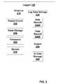
- FIG. 2illustrates further details of Logger 150 , according to various embodiments of the invention.
- Logger 150includes one or more Antenna 210 configured to receive a transmission from a transmitter, such as Transmitter 120 A, Transmitter 120 B, Transmitter/Uploader 130 , and/or the like.
- Antenna 210is optionally further configured to transmit an RF signal to Transmitter/Uploader 130 and/or a conventional RFID reader.
- Antenna 210is optionally tunable or configurable to operate at different frequencies or to exchange signals in particular directions.
- Logger 150includes a Power Circuit 220 configured to convert energy within an RF transmission received by Antenna 210 to electrical energy for operation Logger 150 .
- Power Circuit 220may be configured to generate electrical energy to power a Processor 260 and a Log Data Storage 230 .
- Logger 150includes Log Data Storage 230 configured to store log data.
- the log datais stored in one or more data records, such as a Data Record 240 A and/or Data Record 240 B.
- Log Data Storage 230is configured to store logs of a plurality of events.
- Log Data Storage 230is configured to store over 16, 32, 64, 128, 512, 1024 or 2028 events.
- Log Data Storage 230includes 0.5K, 1K, 2K, 4K, 8K 16K, or 32K bytes, or more, of memory.
- Log Data Storage 230is typically configured to store log data relating to, or received from, Transmitter 120 A, Transmitter 120 B, Transmitter/Uploader 130 , or the like.
- Log Data Storage 230is configured to store time/data information and/or a transmitter ID, received from an RF transmission via Antenna 210 .
- Log Data Storage 230may have stored a series of transmitter IDs, each optionally associated with time/data information. This data may be used to track (in space and time) Logger 150 .
- Log Data Storage 230may include data indicating which instances of Transmitter 120 A, Transmitter 120 B, or Transmitter/Uploader 130 that Logger 150 has passed near and when those events occurred. Precision of the location information may be responsive to the strength of the transmission. For example, Logger 150 must get closer to Transmitter 120 A when the transmission from Transmitter 120 A is weaker, in order for an event to be logged in Logger 150 .
- Log Data Storage 230includes non-volatile memory such as SDRAM, Flash memory, write once memory, or the like.
- Logger 150optionally includes a State Storage 250 configured to store a value indicating if Logger 150 is in the logging mode or the upload mode.
- State Storage 250may be static (e.g., non-volatile) or volatile memory.
- State Storage 250may include SDRAM.
- the value stored in State Storage 250is changed by a command received from Transmitter 120 A, Transmitter 120 B, or Transmitter/Uploader 130 .
- State Storage 250is changed when a transmission is received from Transmitter/Uploader 130 .
- State Storage 250is optional when the mode of Logger 150 is dependent on a communication status (e.g., a good communication link) or a physical connection to Logger 150 .
- Logger 150includes a Processor 260 configured to extract data from a transmission received via Antenna 210 .
- Processor 260may be configured to identify transmitter ID information, time/data data, or a command within a transmission received from Transmitter 120 A, Transmitter 120 B, or Transmitter/Uploader 130 .
- Processor 260may further be configured to change the value stored in State Storage 250 so as to change the mode of Logger 150 between the logging mode and the upload mode.
- Processor 260is configured to manage logging of information received from Transmitter 120 A, Transmitter 120 B, and/or Transmitter/Uploader 130 .
- Processor 260is configured such that only one transmission from a particular transmitter will be logged by a particular Logger 150 in a particular time period. This prevents the Logger 150 from logging multiple events as a result of being in the vicinity of a single transmitter for a period in which the transmitter transmits multiple data.
- a transmittercan be configured to repetitively transmit the same or similar data. For example, the transmitter can transmit a transmitter ID and time/data information continuously. When this transmission is received by Logger 150 the first set of data is logged.
- the predetermined timemay be 1, 5, 10, 60 minutes or longer, depending the specific application for which the instance of Logger 150 is intended.
- the predetermined timemay be stored in Logger 150 or may be part of the transmission received from Transmitter 120 A, Transmitter 120 B, or Transmitter/Uploader 130 .
- a transmitter located at an entrance to a storage are tomay be configured with a one minute predetermined time, while a transmitter located within the storage area may be configured with a 24 hour delay time.
- a transmittermay change transmitter ID in order to control when further data from the same transmitter is logged.
- Logger 150optionally includes a Sensor 270 .
- Sensor 270may be powered by energy generated by Power Circuit 220 using energy received in a transmission to Antenna 210 .
- Sensor 270may be a temperature sensor, humidity sensor, light sensor, environmental sensor, and/or the like.
- Data generated by Sensor 270is optionally stored in Log Data Storage 230 and uploaded to Transmitter/Uploader 130 .
- Logger 150optionally includes an Output 280 configured for uploading data from Log Data Storage 230 to Transmitter/Uploader 130 .
- Output 280is further configured to make electrical or optical contact between Logger 150 and Transmitter/Uploader 130 , the contact being for uploading the data.
- Transmitter/Uploader 130need not include an RF transmitter.
- Output 280includes an electrical contact point, IR transmitter, visible light transmitter, controllable optic, or the like.
- Logger 150optionally includes an ID Data Storage 290 configured to store an ID of Logger 150 , biometric data, personal data, shipping data, inventory data, and/or other data. Data stored in ID Data Storage 290 is optionally uploaded to Transmitter/Uploader 130 using Antenna 210 or Output 280 . Using data stored in ID Data Storage 290 , Logger 150 may operate as an RFID tag. This data stored in ID Data Storage 290 is optionally included in a radio frequency response to a received transmission from Transmitter 120 A, Transmitter 120 B or Transmitter/Uploader 130 .
- Logger 150is configured with a form factor (e.g., shape and size) similar to RFID tags known in the art.
- a form factore.g., shape and size
- a Shipment 140may include one or more instances of Logger 150 configured to tag the entire Shipment 140 and/or specific items within Shipment 140 .
- Shipment 140may be scanned by Transmitter 120 A, Transmitter 120 B, and/or Transmitter/Uploader 130 as it travels along a Path 160 .
- Instances of Transmitter 120 A, Transmitter 120 B, and/or Transmitter/Uploader 130may be located within a single building, within a compound, within a distribution center, within a transportation system, within a supply chain, and/or the like.
- Tracking System 100may include more instances of Transmitter 120 A, Transmitter 120 B, and/or Transmitter/Uploader 130 than is illustrated in FIG. 1 .
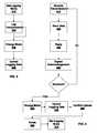
- FIG. 3illustrates a method according to various embodiments of the invention.
- Logger 150is initially placed in the logging mode, transmissions are logged, the mode is changed to the upload mode and data is uploaded.
- a Set Logging Mode Step 310the state of Logger 150 is set to the logging mode.
- Set Logging Mode Step 310places Logger 150 in the logging mode and optionally includes changing a value stored in State Step 250 . This step is optional when the logging mode is the default mode.
- Logger 150is configured to log transmissions received from Transmitter 120 A, Transmitter 120 B, and/or Transmitter/Uploader 130 .
- Set Logging Mode Step 310is performed in response to receipt of a transmission whose energy is insufficient to generate a response transmission.
- the logging modeis optionally set automatically when Power Circuit 220 does not generate at least a predetermined amount of electrical energy.
- Set Logging Mode Step 310is performed in response to failure of a handshaking process in which Logger 150 and Transmitter/Uploader 130 .
- the handshaking processis configured to test and/or confirm the ability of RF communications between Logger 150 and Transmitter/Uploader 130 to accurately communicate data.
- Set Logging Mode Step 310is performed in response to Logger 150 being physically disconnected from a device. For example, if Logger 150 is connected to Transmitter/Uploader 130 , or some other device, via Output 280 , breaking this connection may place Logger 150 in logging mode.
- Set Logging Mode Step 310is performed upon receipt of a command or code from Transmitter 120 A, Transmitter 120 B, and/or Transmitter/Uploader 130 .
- Logger 150may receive data via Antenna 210 .
- the datamay be processed by Processor 260 and, in response, Processor 260 may change a valued stored in State Storage 250 .
- Transmitter 120 A and Transmitter 120 B, and/or Transmitter/Uploader 130are configured to include this command or code near the beginning of their transmission.
- Set Logging Mode Step 310may be performed in response to other criteria and/or events.
- Logger 150logs a transmission from Transmitter 120 A, Transmitter 120 B, and/or Transmitter/Uploader 130 .
- the logged informationis stored in Log Data Storage 230 .
- the logged informationmay include identification data regarding Transmitter 120 A, Transmitter 120 B, and/or Transmitter/Uploader 130 , time/data information, geographic information, sensor data, or the like.
- the logged informationmay be received in the transmission or be generated within Logger 150 .
- a serial number of Transmitter 120 Bmay be received as data within the transmission and sensor data may be generated by Sensor 270 .
- all of the logged datais received within the transmission.
- the logging processis powered by electrical energy generated using Power Circuit 220 from a radio frequency transmission received by Antenna 210 .
- Log Transmission Step 320typically includes receipt of a radio frequency signal from Transmitter 120 A, Transmitter 120 B, and/or Transmitter/Uploader 130 by Antenna 210 . Energy from the transmission is used to generate electrical energy using Power Circuit 220 . The electrical energy is used to power Processor 260 . Processor 260 is used to parse the received transmission to identifying data within the transmission. Some or all of the identified data is stored in Log Data Storage 230 as all or part of the logged information.
- a Change Mode Step 330the mode of Logger 150 is changed to the upload mode.
- datamay be uploaded from Logger 150 to Transmitter/Uploader 130 .
- the uploaded datais data that was stored in Log Data Storage 230 , ID Data Storage 290 , and/or data generated using Sensor 270 .
- the uploadingis accomplished using Antenna 210 .
- the uploadingis optionally powered using electrical energy generated by Power Circuit 220 from a transmission received by Antenna 210 .
- Change Mode Step 330is made in response to receipt of a command from Transmitter 120 A, Transmitter 120 B, and/or Transmitter/Uploader 130 via Antenna 210 .
- Transmitter/Uploader 130may transmit a “SETUPLOADMODE” command to LOGGER 150 .
- the commandis identified by Processor 260 and the mode of Logger 150 is changed in response.
- this mode changeincludes changing a valued in State Storage 250 .
- the SETUPLOADMODE commandmay include a parameter configured to be compared with identification information stored in ID Data Storage.
- This parametermay be used to change the mode of a specific instance of Logger 150 without changing the modes of other instances of Logger 150 .
- Logger 150may be configured to change mode only if the parameter and the identification information match.
- the parametermay be compared with all or part of the identification information in order to change the mode of one or a set of Logger 150 , respectively.
- setting the mode of Logger 150 and/or actually uploading data from Logger 150requires an access code.
- Processor 260may be configured to require this access code.
- the access codeis optionally encrypted.
- Change Mode Step 330occurs in response to making a physical or optical connection to Output 280 .
- Change Mode Step 330may be initiated by physically connecting Logger 150 to Transmitter/Uploader 130 .
- Transmitter/Uploader 130need not include a radio frequency transmitter.
- Change Mode Step 330occurs in response to operation of a switch (not shown) within Logger 150 .
- a switchis disclosed in commonly owned U.S. nonprovisional patent application Ser. No. 11/382,054 filed May 8, 2006 and Ser. No. 11/382,052 filed May 7, 2006. The disclosures of the above nonprovisional patent applications are hereby incorporated herein by reference.
- Change Mode Step 330occurs in response to establishment of communication channel between Transmitter/Uploader 130 and Logger 150 .
- Transmitter/Uploader 130 and Logger 150are configured to undergo a handshaking routine in order to determine the presence of sufficient communication reliability to upload logged data.
- the handshaking routinemay establish that there is sufficient energy to send a response transmission.
- Change Mode Step 330occurs in response to sufficient energy being generated by Power Circuit 220 .
- Logger 150is automatically switched from logging mode to upload mode.
- that the energy has reached the predetermined levelis indicated by a voltage becoming high enough to overcome a junction potential.
- Change Mode Step 330is optionally response to criteria and/or events. Change Mode Step 330 may occur when communications with Logger 150 are easier. For example, the mode of Logger 150 may be changed when items within Shipment 140 have been separated and placed on a conveyer belt. Once an item is on the conveyer belt, Transmitter/Uploader 130 may be disposed closer to Logger 150 and there may be less interference from nearby instances of Logger 150 .
- Step 340data is uploaded from Logger 150 to Transmitter/Uploader 130 .
- the data uploadedcan be data stored in Log Data Storage 230 during the logging mode.
- This stored datacan be representative of a plurality of logging events.
- the stored datamay be representative of various logging events that occurred since the last upload.
- the data uploadedmay further include data stored in ID Data Storage 290 or data generated using Sensor 270 .
- the datais uploaded using Antenna 210 and energy generated using Power Circuit 220 from a transmission received by Antenna 120 .
- the datais uploaded using Output 280 .
- the datais uploaded using power received through a physical or optical connection to Transmitter/Uploader 130 .
- an access codemust be received by Logger 150 before data is uploaded.
- FIG. 4illustrates a plurality of methods according to various embodiments of the invention.
- Logger 150automatically changes between the logging mode and the uploading mode based on communications with Transmitter/Uploader 130 .
- Logger 150changes between logging mode and uploading mode when an instance of Logger 150 is specifically addressed using identification data for the instance of Logger 150 .
- Logger 150changes between the logging mode and the uploading mode responsive to one or more commands received through an RF transmission.
- Logger 150changes between logging mode and uploading mode responsive to manipulation of an optical, a mechanical or electrical switch included in Logger 150 .
- Logger 150receives a transmission from an instance of Transmitter/Uploader 130 .
- This transmissionis received by Antenna 210 and is used by Power Circuit 220 to generate electrical power.
- the transmissionoptionally includes data configured to identify the instance of Transmitter/Uploader 130 , time/date data, sensor data, commands, codes, or the like.
- Data received in the transmission of Receive Transmission Step 410is stored in Log Data Storage 230 .
- This datamay be stored in a Data Record 240 A or 240 B.
- the storage processis powered by electrical energy produced by Power Circuit 220 from the received transmission.
- Logger 150uses Antenna 210 to send a response signal to Transmitter/Uploader 130 .
- This response signaloptionally includes data identifying Logger 150 .
- the responsemay include identification data retrieved from ID Data Storage 290 .
- Reply Step 430optionally includes setting a state variable in static memory within Logger 150 . This state variable may be used to determine that a response signal has been sent to a particular instance of Transmitter/Uploader 130 , when Logger 150 next operates.
- Logger 150determines if an acknowledgement of the response signal has been received by Logger 150 from Transmitter/Uploader 130 .
- the acknowledgementoptionally includes information identifying it as an acknowledgement.
- the acknowledgementfurther optionally includes data identifying the particular instance of Logger 150 .
- the receipt of an acknowledgement address to a particular instance of Logger 150is interpreted by the Logger 150 as an indication that the prior steps have already occurred.
- the methodreturns to receive Transmission Step 410 . If an acknowledgement is received, then the method proceeds to Change Mode Step 330 and Upload Logging Data Step 340 .
- Logger 150communicates with Transmitter/Uploader 130 in order to confirm successful uploading of the data in Upload Logging Data Step 340 .
- this communicationincludes a transmission from Transmitter/Uploader 340 to Logger 150 confirming receipt of the data.
- Delete Step 460the uploaded data is deleted from Log Data Storage 230 .
- Delete Step 460may be conditional on receiving the confirmation of Confirm Upload Step 450 .
- Logger 150is set back to the logging mode.
- the logging modemay include transmissions from Logger 150 to Transmitter 120 A, Transmitter 120 B, and/or Transmitter/Uploader 130 .
- Logger 150may optionally operate in response to Transmitter 120 A or Transmitter 120 B as a prior art RFID tag with the exception that transmissions are logged and logging information stored in Logger 150 .
- Logger 150is configured to operate in three modes: an RFID mode of the prior art, the logging mode and the uploading mode. These modes are not necessarily mutually exclusive.
- the RFID modemay be combined with aspects of the logging mode and the uploading mode.
- Logger 150is optionally included in an identity documents such as a driver's license, passport, immigration document, vehicle registration, immigration document, membership card, key card, library card, student card, or the like.
- Logger 150is optionally included in a financial instrument such as a credit card, debit card, bank card, check cart, traveler's check, payment fob, or the like.
- Logger 150may be configured to log passage through an immigration point, travel, or a financial transaction, etc. Such logging may be used to prevent fraud.
Landscapes
- Engineering & Computer Science (AREA)
- Physics & Mathematics (AREA)
- General Physics & Mathematics (AREA)
- Theoretical Computer Science (AREA)
- Computer Hardware Design (AREA)
- Microelectronics & Electronic Packaging (AREA)
- Computer Networks & Wireless Communication (AREA)
- Computer Security & Cryptography (AREA)
- General Engineering & Computer Science (AREA)
- Arrangements For Transmission Of Measured Signals (AREA)
Abstract
Description
Claims (30)
Priority Applications (21)
| Application Number | Priority Date | Filing Date | Title |
|---|---|---|---|
| US12/577,209US8816826B2 (en) | 2005-05-06 | 2009-10-12 | Passive radio frequency data logger |
| US14/468,110US9495852B1 (en) | 2005-05-06 | 2014-08-25 | Electronically switchable RFID tags |
| US14/659,072US20150254951A1 (en) | 2005-02-07 | 2015-03-16 | RFID Security System |
| US14/660,927US20150254483A1 (en) | 2005-02-07 | 2015-03-17 | RFID Sensor |
| US14/660,825US9569777B2 (en) | 2005-02-07 | 2015-03-17 | EPassport including shielding method |
| US14/660,907US9524458B2 (en) | 2005-02-07 | 2015-03-17 | Switchable epassport including shielding |
| US15/418,726US10503940B2 (en) | 2005-02-07 | 2017-01-28 | Secure passport reading |
| US15/435,231US10810578B2 (en) | 2005-02-07 | 2017-02-16 | RFID financial device including mechanical switch |
| US16/186,542US11295095B2 (en) | 2005-02-07 | 2018-11-11 | Secure reading of passport RFID tags |
| US16/186,545US10417462B2 (en) | 2005-02-07 | 2018-11-11 | Passport including readability states |
| US16/186,566US10417463B2 (en) | 2005-02-07 | 2018-11-11 | Passport RFID readability |
| US16/186,568US10650199B2 (en) | 2005-02-07 | 2018-11-11 | Passport including metallic fibers |
| US16/186,543US11170185B2 (en) | 2005-02-07 | 2018-11-11 | State dependent passport reading |
| US16/186,544US10592709B2 (en) | 2005-02-07 | 2018-11-11 | Passport shield |
| US16/186,567US10956689B2 (en) | 2005-02-07 | 2018-11-11 | Passport including RFID shielding |
| US17/075,633US11270182B2 (en) | 2005-02-07 | 2020-10-20 | RFID financial device including mechanical switch |
| US17/522,697US11347949B2 (en) | 2005-05-06 | 2021-11-09 | Cellular device including inductive antenna |
| US17/697,923US11599734B2 (en) | 2005-05-06 | 2022-03-18 | Methods of inductive communication in a cellular telephone |
| US17/728,412US11989612B1 (en) | 2005-05-06 | 2022-04-25 | Cellular telephone including biometric sensor |
| US17/952,176US11687741B1 (en) | 2005-05-06 | 2022-09-23 | Methods of using a cellular telephone |
| US18/422,929US12039396B2 (en) | 2005-05-06 | 2024-01-25 | Cellular telephone including biometric control of transactions |
Applications Claiming Priority (13)
| Application Number | Priority Date | Filing Date | Title |
|---|---|---|---|
| US67842805P | 2005-05-06 | 2005-05-06 | |
| US68533105P | 2005-05-27 | 2005-05-27 | |
| US70088405P | 2005-07-19 | 2005-07-19 | |
| US71230805P | 2005-08-30 | 2005-08-30 | |
| US71564105P | 2005-09-10 | 2005-09-10 | |
| US75293305P | 2005-12-21 | 2005-12-21 | |
| US75875106P | 2006-01-13 | 2006-01-13 | |
| US78206806P | 2006-03-13 | 2006-03-13 | |
| US74415406P | 2006-04-03 | 2006-04-03 | |
| US74663606P | 2006-05-06 | 2006-05-06 | |
| US11/382,054US20070200682A1 (en) | 2005-05-06 | 2006-05-08 | RFID Device Including Multiple Active Modes |
| US46802606A | 2006-08-29 | 2006-08-29 | |
| US12/577,209US8816826B2 (en) | 2005-05-06 | 2009-10-12 | Passive radio frequency data logger |
Related Parent Applications (4)
| Application Number | Title | Priority Date | Filing Date |
|---|---|---|---|
| US11/382,050Continuation-In-PartUS20070200679A1 (en) | 2005-02-07 | 2006-05-07 | RFID Device Including Multiple RFID Tags |
| US11/382,052Continuation-In-PartUS20070200680A1 (en) | 2005-02-07 | 2006-05-07 | Transaction Card Including Switchable RFID Tag |
| US11/382,054Continuation-In-PartUS20070200682A1 (en) | 2005-02-07 | 2006-05-08 | RFID Device Including Multiple Active Modes |
| US46802606AContinuation | 2005-02-07 | 2006-08-29 |
Related Child Applications (3)
| Application Number | Title | Priority Date | Filing Date |
|---|---|---|---|
| US77747410AContinuation | 2005-02-07 | 2010-05-11 | |
| US14/468,110ContinuationUS9495852B1 (en) | 2005-02-07 | 2014-08-25 | Electronically switchable RFID tags |
| US14/468,110Continuation-In-PartUS9495852B1 (en) | 2005-02-07 | 2014-08-25 | Electronically switchable RFID tags |
Publications (2)
| Publication Number | Publication Date |
|---|---|
| US20100026466A1 US20100026466A1 (en) | 2010-02-04 |
| US8816826B2true US8816826B2 (en) | 2014-08-26 |
Family
ID=46332352
Family Applications (1)
| Application Number | Title | Priority Date | Filing Date |
|---|---|---|---|
| US12/577,209Expired - Fee RelatedUS8816826B2 (en) | 2005-02-07 | 2009-10-12 | Passive radio frequency data logger |
Country Status (1)
| Country | Link |
|---|---|
| US (1) | US8816826B2 (en) |
Cited By (8)
| Publication number | Priority date | Publication date | Assignee | Title |
|---|---|---|---|---|
| US20130191497A1 (en)* | 2012-01-25 | 2013-07-25 | International Business Machines Corporation | Storage and Transmission of Log Data In a Networked System |
| US9286594B1 (en) | 2013-11-08 | 2016-03-15 | Sprint Communications Company L.P. | Visually readable electronic label |
| US9324016B1 (en) | 2013-04-04 | 2016-04-26 | Sprint Communications Company L.P. | Digest of biographical information for an electronic device with static and dynamic portions |
| US9396424B1 (en) | 2014-11-04 | 2016-07-19 | Sprint Communications Company L.P. | Radio frequency induced power reception management for a radio frequency identity (RFID) chip embedded in a mobile communication device |
| US9426604B1 (en)* | 2013-04-30 | 2016-08-23 | Sprint Communications Company L.P. | Prevention of inductive coupling between components of a mobile communication device |
| US9454723B1 (en) | 2013-04-04 | 2016-09-27 | Sprint Communications Company L.P. | Radio frequency identity (RFID) chip electrically and communicatively coupled to motherboard of mobile communication device |
| US9460573B1 (en) | 2014-02-27 | 2016-10-04 | Sprint Communications Company, L.P. | Autonomous authentication of a reader by a radio frequency identity (RFID) device |
| US9591434B1 (en)* | 2015-04-27 | 2017-03-07 | Sprint Communications Company L.P. | Virtual private network (VPN) tunneling in a user equipment (UE) brokered by a radio frequency identity (RFID) chip communicatively coupled to the user equipment |
Families Citing this family (3)
| Publication number | Priority date | Publication date | Assignee | Title |
|---|---|---|---|---|
| US10339619B2 (en)* | 2015-08-25 | 2019-07-02 | Scott Arthur William Muirhead | Method and apparatus for presenting supply chain information to a consumer |
| JP6959786B2 (en)* | 2017-07-27 | 2021-11-05 | 株式会社ダイヘン | Power phase shifter |
| US20240380481A1 (en)* | 2023-05-13 | 2024-11-14 | Cisco Technology, Inc. | Backscatter device onboarding |
Citations (73)
| Publication number | Priority date | Publication date | Assignee | Title |
|---|---|---|---|---|
| US4575601A (en) | 1981-02-19 | 1986-03-11 | Sharp Kabushiki Kaisha | Keyboard of the membrane type |
| US4744497A (en) | 1986-12-10 | 1988-05-17 | Neal William T O | Security wallet |
| US5206495A (en) | 1989-10-24 | 1993-04-27 | Angewandte Digital Elektronik Gmbh | Chip card |
| US5327115A (en) | 1992-07-29 | 1994-07-05 | Remi Swierczek | Programmable document clip |
| US5380046A (en) | 1993-08-30 | 1995-01-10 | Stephens; Gregory W. | Secured personal information packet |
| US5506395A (en) | 1994-06-22 | 1996-04-09 | William C. Eppley | Multi-access card and card holder with a plurality of machine readable service access codes placed thereon |
| US5521590A (en) | 1902-10-02 | 1996-05-28 | Citizen Watch Co., Ltd. | Data carrier |
| US5538291A (en) | 1994-09-26 | 1996-07-23 | Gustafson; Ulf | Anti-theft credit card |
| US5640151A (en) | 1990-06-15 | 1997-06-17 | Texas Instruments Incorporated | Communication system for communicating with tags |
| US5700037A (en) | 1996-01-16 | 1997-12-23 | Keller; John A. | Security improved card |
| US5847662A (en) | 1994-12-27 | 1998-12-08 | Kabushiki Kaisha Toshiba | Radio card communication apparatus |
| US5966082A (en) | 1997-05-23 | 1999-10-12 | Intemec Ip Corp. | Method of flagging partial write in RF tags |
| WO2000016570A1 (en) | 1998-09-11 | 2000-03-23 | Motorola Inc. | Electrostatic radio frequency identification system having contactless programmability |
| US6130602A (en) | 1996-05-13 | 2000-10-10 | Micron Technology, Inc. | Radio frequency data communications device |
| US6144299A (en)* | 1996-07-05 | 2000-11-07 | Integrated Silicon Design Pty. Ltd. | Presence and data labels |
| US6158777A (en) | 1994-11-28 | 2000-12-12 | Twardosz; Brian M | Information sheet and a method for its folding |
| US6199762B1 (en) | 1998-05-06 | 2001-03-13 | American Express Travel Related Services Co., Inc. | Methods and apparatus for dynamic smartcard synchronization and personalization |
| US6282407B1 (en) | 1998-04-16 | 2001-08-28 | Motorola, Inc. | Active electrostatic transceiver and communicating system |
| US20010017799A1 (en)* | 2000-02-18 | 2001-08-30 | Chen Joey Y. | Efficient memory allocation scheme for data collection |
| US6320169B1 (en) | 1999-09-07 | 2001-11-20 | Thermal Solutions, Inc. | Method and apparatus for magnetic induction heating using radio frequency identification of object to be heated |
| US20020017557A1 (en)* | 1999-02-18 | 2002-02-14 | Colin Hendrick | System for automatic connection to a network |
| US20020047777A1 (en) | 1998-12-14 | 2002-04-25 | Casden Martin S. | Wireless data input to RFID reader |
| US20020117243A1 (en) | 2000-06-12 | 2002-08-29 | Koren James A. | Credit card holder |
| US6471127B2 (en) | 2000-07-06 | 2002-10-29 | Bank Of America Corporation | Data card |
| US20030014891A1 (en) | 2000-12-08 | 2003-01-23 | Nelms David W. | Non-rectangular shaped credit card with case |
| US20030030568A1 (en)* | 2001-06-14 | 2003-02-13 | Roc Lastinger | Wireless identification systems and protocols |
| US20030042318A1 (en)* | 2001-08-31 | 2003-03-06 | Ksheerabdhi Krishna | Method and apparatus for linking converted applet files |
| US6531964B1 (en) | 1999-02-25 | 2003-03-11 | Motorola, Inc. | Passive remote control system |
| US20030057286A1 (en) | 2001-09-26 | 2003-03-27 | Hitachi Electronic Service Co., Ltd. | Passport with anti-counterfeit ID chip |
| US6593845B1 (en) | 1998-01-09 | 2003-07-15 | Intermac Ip Corp. | Active RF tag with wake-up circuit to prolong battery life |
| US20030209601A1 (en)* | 2000-10-11 | 2003-11-13 | Chung Kevin Kwong-Tai | Article tracking system and method |
| US6719206B1 (en) | 1997-11-19 | 2004-04-13 | On Track Innovations Ltd. | Data transaction card and method of manufacture thereof |
| US20040089724A1 (en) | 2002-11-07 | 2004-05-13 | Ellen Lasch | Foldable transaction card |
| US20040145453A1 (en) | 2002-04-01 | 2004-07-29 | Tuttle Mark E. | Wireless identification device, RFID device with push-on/push off switch, and method of manufacturing wireless identification device |
| US20040169087A1 (en) | 2002-12-11 | 2004-09-02 | Ellen Lasch | Foldable transaction card systems |
| US20040212503A1 (en)* | 2003-02-03 | 2004-10-28 | Stilp Louis A. | Communications architecture for a security network |
| US20040233040A1 (en) | 2002-11-23 | 2004-11-25 | Kathleen Lane | Secure personal RFID documents and method of use |
| US20040237360A1 (en) | 2001-07-20 | 2004-12-02 | Nelms David W. | Credit card with case |
| US20040256469A1 (en) | 1999-09-07 | 2004-12-23 | American Express Travel Related Services Company, Inc. | A system and method for manufacturing a punch-out rfid transaction device |
| US20040263319A1 (en) | 2003-06-30 | 2004-12-30 | Nokia Corporation | System and method for supporting multiple reader-tag configurations using multi-mode radio frequency tag |
| US20050011776A1 (en) | 2003-07-14 | 2005-01-20 | Nagel Richard R. | Easy access credit card holder |
| US20050093703A1 (en)* | 2000-12-22 | 2005-05-05 | Twitchell Robert W.Jr. | Systems and methods having LPRF device wake up using wireless tag |
| US20050145688A1 (en)* | 2003-12-29 | 2005-07-07 | Milan Milenkovic | Asset management methods and apparatus |
| US20050171898A1 (en) | 2001-07-10 | 2005-08-04 | American Express Travel Related Services Company, Inc. | Systems and methods for managing multiple accounts on a rf transaction device using secondary identification indicia |
| US20050174239A1 (en) | 2001-02-12 | 2005-08-11 | Symbol Technologies, Inc. | Radio frequency identification tag antenna configurations |
| US20050192053A1 (en) | 2004-02-27 | 2005-09-01 | Jigatek Corporation | Method and apparatus for radio frequency identification |
| US20050205665A1 (en) | 2003-12-10 | 2005-09-22 | Ellen Lasch | Foldable transaction card systems for non-traditionally-sized transaction cards |
| US20050207229A1 (en)* | 2004-03-22 | 2005-09-22 | Ken Takeuchi | Nonvolatile semiconductor memory |
| US20050242950A1 (en) | 2004-04-30 | 2005-11-03 | Kimberly-Clark Worldwide, Inc. | Activating a data tag by load or orientation or user control |
| US20050253683A1 (en) | 2004-05-17 | 2005-11-17 | Identification Technology Group | Biometrically authenticated portable access device |
| US20050263591A1 (en) | 2003-08-09 | 2005-12-01 | Smith John S | Methods and apparatuses to identify devices |
| US20050274794A1 (en) | 2004-06-10 | 2005-12-15 | Eli Bason | Smart identification document |
| US7015791B2 (en) | 2003-08-19 | 2006-03-21 | General Motors Corporation | Keyless entry module and method |
| US20060109084A1 (en)* | 2004-11-24 | 2006-05-25 | Mark Yarvis | Mesh networking with RFID communications |
| US20060164250A1 (en) | 2003-08-29 | 2006-07-27 | Wakahiro Kawai | Wireless ic tag joining method, wireless ic tag-carrying article, and vehicle |
| US20060186989A1 (en) | 2005-02-07 | 2006-08-24 | Samsung Electronics Co., Ltd. | RFID tag for protecting information and method for protecting personal information |
| US20060187040A1 (en) | 2005-02-04 | 2006-08-24 | Philip Morris Usa Inc. | Controllable RFID card |
| US20060245530A1 (en)* | 2005-04-29 | 2006-11-02 | Pradhan Salil V | Communication with a mobile device |
| US20060254815A1 (en) | 2005-04-26 | 2006-11-16 | Humphrey Thomas W | Radiofrequency identification shielding |
| US20070024423A1 (en) | 2005-07-28 | 2007-02-01 | Intermec Ip Corp. | Automatic data collection device, method and article |
| US20070057790A1 (en) | 2005-09-12 | 2007-03-15 | Alden Ray M | RFID transponder arrays for sensing input and controlling processes |
| US20070057792A1 (en) | 2005-09-12 | 2007-03-15 | Alden Ray M | Contact arrays and processes for wireless batteryless user input |
| US20070075140A1 (en) | 2005-10-04 | 2007-04-05 | Gregory Guez | Means to deactivate a contactless device |
| US20070090927A1 (en) | 2005-10-26 | 2007-04-26 | General Electric Company | Chemical and biological sensors, systems and methods based on radio frequency identification |
| US7218233B2 (en) | 2003-12-02 | 2007-05-15 | Ask S.A. | Identity booklet with a radiofrequency identification device |
| US20070152829A1 (en) | 2004-04-30 | 2007-07-05 | Kimberly-Clark Worldwide, Inc. | Reversibly deactivating a radio frequency identification data tag |
| US7246754B2 (en) | 2004-02-18 | 2007-07-24 | Hewlett-Packard Development Company, L.P. | Secure currency |
| US20070194116A1 (en) | 2002-06-04 | 2007-08-23 | Siegfried Arnold | Roll back method for a smart card |
| US7290709B2 (en) | 2001-04-10 | 2007-11-06 | Erica Tsai | Information card system |
| US20080238679A1 (en) | 2007-03-30 | 2008-10-02 | Broadcom Corporation | Multi-mode rfid tag architecture |
| US7591415B2 (en) | 2004-09-28 | 2009-09-22 | 3M Innovative Properties Company | Passport reader for processing a passport having an RFID element |
| US7719425B2 (en) | 2005-02-07 | 2010-05-18 | Colby Steven M | Radio frequency shielding |
| US7924156B2 (en) | 2005-05-06 | 2011-04-12 | Colby Steven M | Electronically switchable RFID tags |
- 2009
- 2009-10-12USUS12/577,209patent/US8816826B2/ennot_activeExpired - Fee Related
Patent Citations (77)
| Publication number | Priority date | Publication date | Assignee | Title |
|---|---|---|---|---|
| US5521590A (en) | 1902-10-02 | 1996-05-28 | Citizen Watch Co., Ltd. | Data carrier |
| US4575601A (en) | 1981-02-19 | 1986-03-11 | Sharp Kabushiki Kaisha | Keyboard of the membrane type |
| US4744497A (en) | 1986-12-10 | 1988-05-17 | Neal William T O | Security wallet |
| US5206495A (en) | 1989-10-24 | 1993-04-27 | Angewandte Digital Elektronik Gmbh | Chip card |
| US5686902A (en) | 1990-06-15 | 1997-11-11 | Texas Instruments Incorporated | Communication system for communicating with tags |
| US5640151A (en) | 1990-06-15 | 1997-06-17 | Texas Instruments Incorporated | Communication system for communicating with tags |
| US5327115A (en) | 1992-07-29 | 1994-07-05 | Remi Swierczek | Programmable document clip |
| US5380046A (en) | 1993-08-30 | 1995-01-10 | Stephens; Gregory W. | Secured personal information packet |
| US5506395A (en) | 1994-06-22 | 1996-04-09 | William C. Eppley | Multi-access card and card holder with a plurality of machine readable service access codes placed thereon |
| US5538291A (en) | 1994-09-26 | 1996-07-23 | Gustafson; Ulf | Anti-theft credit card |
| US6158777A (en) | 1994-11-28 | 2000-12-12 | Twardosz; Brian M | Information sheet and a method for its folding |
| US5847662A (en) | 1994-12-27 | 1998-12-08 | Kabushiki Kaisha Toshiba | Radio card communication apparatus |
| US5700037A (en) | 1996-01-16 | 1997-12-23 | Keller; John A. | Security improved card |
| US6130602A (en) | 1996-05-13 | 2000-10-10 | Micron Technology, Inc. | Radio frequency data communications device |
| US6144299A (en)* | 1996-07-05 | 2000-11-07 | Integrated Silicon Design Pty. Ltd. | Presence and data labels |
| US5966082A (en) | 1997-05-23 | 1999-10-12 | Intemec Ip Corp. | Method of flagging partial write in RF tags |
| US6719206B1 (en) | 1997-11-19 | 2004-04-13 | On Track Innovations Ltd. | Data transaction card and method of manufacture thereof |
| US6593845B1 (en) | 1998-01-09 | 2003-07-15 | Intermac Ip Corp. | Active RF tag with wake-up circuit to prolong battery life |
| US6282407B1 (en) | 1998-04-16 | 2001-08-28 | Motorola, Inc. | Active electrostatic transceiver and communicating system |
| US6199762B1 (en) | 1998-05-06 | 2001-03-13 | American Express Travel Related Services Co., Inc. | Methods and apparatus for dynamic smartcard synchronization and personalization |
| WO2000016570A1 (en) | 1998-09-11 | 2000-03-23 | Motorola Inc. | Electrostatic radio frequency identification system having contactless programmability |
| US20020047777A1 (en) | 1998-12-14 | 2002-04-25 | Casden Martin S. | Wireless data input to RFID reader |
| US20020017557A1 (en)* | 1999-02-18 | 2002-02-14 | Colin Hendrick | System for automatic connection to a network |
| US6531964B1 (en) | 1999-02-25 | 2003-03-11 | Motorola, Inc. | Passive remote control system |
| US6320169B1 (en) | 1999-09-07 | 2001-11-20 | Thermal Solutions, Inc. | Method and apparatus for magnetic induction heating using radio frequency identification of object to be heated |
| US20030095034A1 (en) | 1999-09-07 | 2003-05-22 | Clothier Brian L. | Method and apparatus for magnetic induction heating using radio frequency identification of object to be heated |
| US20040256469A1 (en) | 1999-09-07 | 2004-12-23 | American Express Travel Related Services Company, Inc. | A system and method for manufacturing a punch-out rfid transaction device |
| US20010017799A1 (en)* | 2000-02-18 | 2001-08-30 | Chen Joey Y. | Efficient memory allocation scheme for data collection |
| US20020117243A1 (en) | 2000-06-12 | 2002-08-29 | Koren James A. | Credit card holder |
| US6471127B2 (en) | 2000-07-06 | 2002-10-29 | Bank Of America Corporation | Data card |
| US20030209601A1 (en)* | 2000-10-11 | 2003-11-13 | Chung Kevin Kwong-Tai | Article tracking system and method |
| US20030014891A1 (en) | 2000-12-08 | 2003-01-23 | Nelms David W. | Non-rectangular shaped credit card with case |
| US20050093703A1 (en)* | 2000-12-22 | 2005-05-05 | Twitchell Robert W.Jr. | Systems and methods having LPRF device wake up using wireless tag |
| US20050174239A1 (en) | 2001-02-12 | 2005-08-11 | Symbol Technologies, Inc. | Radio frequency identification tag antenna configurations |
| US7290709B2 (en) | 2001-04-10 | 2007-11-06 | Erica Tsai | Information card system |
| US20030030568A1 (en)* | 2001-06-14 | 2003-02-13 | Roc Lastinger | Wireless identification systems and protocols |
| US20050171898A1 (en) | 2001-07-10 | 2005-08-04 | American Express Travel Related Services Company, Inc. | Systems and methods for managing multiple accounts on a rf transaction device using secondary identification indicia |
| US20040237360A1 (en) | 2001-07-20 | 2004-12-02 | Nelms David W. | Credit card with case |
| US20030042318A1 (en)* | 2001-08-31 | 2003-03-06 | Ksheerabdhi Krishna | Method and apparatus for linking converted applet files |
| US20030057286A1 (en) | 2001-09-26 | 2003-03-27 | Hitachi Electronic Service Co., Ltd. | Passport with anti-counterfeit ID chip |
| US20040145453A1 (en) | 2002-04-01 | 2004-07-29 | Tuttle Mark E. | Wireless identification device, RFID device with push-on/push off switch, and method of manufacturing wireless identification device |
| US20070194116A1 (en) | 2002-06-04 | 2007-08-23 | Siegfried Arnold | Roll back method for a smart card |
| US20040089724A1 (en) | 2002-11-07 | 2004-05-13 | Ellen Lasch | Foldable transaction card |
| US20040233040A1 (en) | 2002-11-23 | 2004-11-25 | Kathleen Lane | Secure personal RFID documents and method of use |
| US20040169087A1 (en) | 2002-12-11 | 2004-09-02 | Ellen Lasch | Foldable transaction card systems |
| US20040212503A1 (en)* | 2003-02-03 | 2004-10-28 | Stilp Louis A. | Communications architecture for a security network |
| US7446646B2 (en) | 2003-06-30 | 2008-11-04 | Nokia Corporation | System and method for supporting multiple reader-tag configurations using multi-mode radio frequency tag |
| US20040263319A1 (en) | 2003-06-30 | 2004-12-30 | Nokia Corporation | System and method for supporting multiple reader-tag configurations using multi-mode radio frequency tag |
| US20050011776A1 (en) | 2003-07-14 | 2005-01-20 | Nagel Richard R. | Easy access credit card holder |
| US20050263591A1 (en) | 2003-08-09 | 2005-12-01 | Smith John S | Methods and apparatuses to identify devices |
| US7015791B2 (en) | 2003-08-19 | 2006-03-21 | General Motors Corporation | Keyless entry module and method |
| US20060164250A1 (en) | 2003-08-29 | 2006-07-27 | Wakahiro Kawai | Wireless ic tag joining method, wireless ic tag-carrying article, and vehicle |
| US7218233B2 (en) | 2003-12-02 | 2007-05-15 | Ask S.A. | Identity booklet with a radiofrequency identification device |
| US20050205665A1 (en) | 2003-12-10 | 2005-09-22 | Ellen Lasch | Foldable transaction card systems for non-traditionally-sized transaction cards |
| US20050145688A1 (en)* | 2003-12-29 | 2005-07-07 | Milan Milenkovic | Asset management methods and apparatus |
| US7246754B2 (en) | 2004-02-18 | 2007-07-24 | Hewlett-Packard Development Company, L.P. | Secure currency |
| US20050192053A1 (en) | 2004-02-27 | 2005-09-01 | Jigatek Corporation | Method and apparatus for radio frequency identification |
| US20050207229A1 (en)* | 2004-03-22 | 2005-09-22 | Ken Takeuchi | Nonvolatile semiconductor memory |
| US20070152829A1 (en) | 2004-04-30 | 2007-07-05 | Kimberly-Clark Worldwide, Inc. | Reversibly deactivating a radio frequency identification data tag |
| US20050242950A1 (en) | 2004-04-30 | 2005-11-03 | Kimberly-Clark Worldwide, Inc. | Activating a data tag by load or orientation or user control |
| US20050253683A1 (en) | 2004-05-17 | 2005-11-17 | Identification Technology Group | Biometrically authenticated portable access device |
| US20050274794A1 (en) | 2004-06-10 | 2005-12-15 | Eli Bason | Smart identification document |
| US20060005050A1 (en) | 2004-06-10 | 2006-01-05 | Supercom Ltd. | Tamper-free and forgery-proof passport and methods for providing same |
| US7591415B2 (en) | 2004-09-28 | 2009-09-22 | 3M Innovative Properties Company | Passport reader for processing a passport having an RFID element |
| US20060109084A1 (en)* | 2004-11-24 | 2006-05-25 | Mark Yarvis | Mesh networking with RFID communications |
| US20060187040A1 (en) | 2005-02-04 | 2006-08-24 | Philip Morris Usa Inc. | Controllable RFID card |
| US20060186989A1 (en) | 2005-02-07 | 2006-08-24 | Samsung Electronics Co., Ltd. | RFID tag for protecting information and method for protecting personal information |
| US7719425B2 (en) | 2005-02-07 | 2010-05-18 | Colby Steven M | Radio frequency shielding |
| US20060254815A1 (en) | 2005-04-26 | 2006-11-16 | Humphrey Thomas W | Radiofrequency identification shielding |
| US20060245530A1 (en)* | 2005-04-29 | 2006-11-02 | Pradhan Salil V | Communication with a mobile device |
| US7924156B2 (en) | 2005-05-06 | 2011-04-12 | Colby Steven M | Electronically switchable RFID tags |
| US20070024423A1 (en) | 2005-07-28 | 2007-02-01 | Intermec Ip Corp. | Automatic data collection device, method and article |
| US20070057792A1 (en) | 2005-09-12 | 2007-03-15 | Alden Ray M | Contact arrays and processes for wireless batteryless user input |
| US20070057790A1 (en) | 2005-09-12 | 2007-03-15 | Alden Ray M | RFID transponder arrays for sensing input and controlling processes |
| US20070075140A1 (en) | 2005-10-04 | 2007-04-05 | Gregory Guez | Means to deactivate a contactless device |
| US20070090927A1 (en) | 2005-10-26 | 2007-04-26 | General Electric Company | Chemical and biological sensors, systems and methods based on radio frequency identification |
| US20080238679A1 (en) | 2007-03-30 | 2008-10-02 | Broadcom Corporation | Multi-mode rfid tag architecture |
Non-Patent Citations (39)
| Title |
|---|
| "RFID Powder" Scientific American, pp. 68-71, Feb. 2008. |
| Carlos Vila Deutschbein, "Digital Frequency Shifting for Electroacoustic Feedback Suppression" in Audo Engineering Society Conventino Paper. Present at the 118th Convention May 28-31, 2005 Barcelona, Spain. (p. 1). |
| Goo, Sara Kehaulani, Security Concerns Prompt Passport Redesign, www.washingtonpost.com, Apr. 30, 2005, 3 pages. |
| Juels, Ari, et al., Security and Privacy Issues in E-passports, SECURECOMM'05, vol. 00 2005, Sep. 5, 2009, 13 pages. |
| Moss, Frank, How the U.S. Passport Program Enhances Border Security, travel.state.gov, Jun. 22, 2005, 5 pages. |
| Moss, Frank, Statement, Committee on International Relations, wwwc.house.gov, Jun. 23, 2004, 4 pages. |
| PCT/US99/21073, International Search Report dated Dec. 2, 1999, 3 pages. |
| Peterson, Erik, Issues First e-passports to diplomats, citizen issuance to start later in '06, SecureID News, Apr. 20, 2006, 3 pages. |
| RFID Powder, Scientific American, Feb. 2008, 6 pages. |
| Schneier, Bruce, Schneier on Security, a Weblog Covering Security and Security Technology, Aug. 9, 2005, 19 pages. |
| Schneier, Bruce, Schneier on Security, A Weblog Covering Security and Security Technology, Nov. 3, 2005, 18 pages. |
| U.S. Appl. No. 11/350,309, filed Feb. 27, 2006, Colby, Steven M., Final Office Action issued Sep. 23, 2009, 15 pages. |
| U.S. Appl. No. 11/350,309, filed Feb. 27, 2006, Colby, Steven M., Non-Final Office Action issued Feb. 19, 2008, 5 pages. |
| U.S. Appl. No. 11/350,309, filed Feb. 27, 2006, Colby, Steven M., Non-Final Office Action issued Jan. 12, 2009, 14 pages. |
| U.S. Appl. No. 11/350,309, filed Feb. 27, 2006, Colby, Steven M., Non-Final Office Action issued May 14, 2008, 9 pages. |
| U.S. Appl. No. 11/350,309, filed Feb. 27, 2006, Colby, Steven M., Notice of Allowance and Allowability, issued Jan. 11, 2010. |
| U.S. Appl. No. 11/382,050, filed May 7, 2006, Colby, Steven M., Non-Final Office Action issued Apr. 8, 2009, 15 pages. |
| U.S. Appl. No. 11/382,052 filed May 7, 2006, Colby, Steven M., Non-Final Office Action issued Apr. 8, 2009, 18 pages. |
| U.S. Appl. No. 11/382,053, filed May 7, 2006, Colby, Steven M., Non-Final Office Action issued Apr. 8, 2009, 19 pages. |
| U.S. Appl. No. 11/382,054, filed May 8, 2006, Colby, Steven M., Non-Final Office Action issued Apr. 10, 2009, 17 pages. |
| U.S. Appl. No. 11/382,265, filed May 8, 2006, Colby, Steven M., Non-Final Office Action issued Apr. 10, 2009, 16 pages. |
| U.S. Appl. No. 11/420,721, filed May 26, 2006, Colby, Steven M., Non-Final Office Action issued Apr. 8, 2009, 18 pages. |
| U.S. Appl. No. 11/458,620, filed Jul. 19, 2006, Colby, Steven M., Non-Final Office Action issued Dec. 14, 2009. |
| U.S. Appl. No. 11/458,620, filed Jul. 19, 2006, Colby, Steven M., Non-Final Office Action issued Jun. 24, 2010, 6 pages. |
| U.S. Appl. No. 11/458,620, filed Jul. 19, 2006, Colby, Steven M., Non-Final office Action issued Mar. 30, 2009, 19 pages. |
| U.S. Appl. No. 11/468,026, filed Aug. 29, 2006, Colby, Steven M., Non-Final Office Action issued Apr. 10, 2009, 22 pages. |
| U.S. Appl. No. 12/577,2009, filed Oct. 12, 2009, Colby, Steven M. Final Rejection, 24 pages. |
| U.S. Appl. No. 12/577,209, filed Oct. 12, 2009, Colby, Steven M., Non-Final Office Action issued Mar. 21, 2012, 22 pages. |
| U.S. Appl. No. 12/777,474, filed May 11, 2010, Colby, Steven M., Non-Final Office Action issued Dec. 28, 2011, 13 pages. |
| U.S. Appl. No. 12/777,474, filed May 11, 2010, Colby, Steven M., Non-Final Office Action issued Feb. 18, 2011, 7 pages. |
| U.S. Appl. No. 13/084,433, filed Apr. 11, 2011, Colby, Steven M., entitled Transaction Card Including Switchable RFID Tag. |
| Unknown CDT Working Group on RFID: Privacy Best Practices for Deployment of RFID Technology, www.cdt.org, May 1, 2006, 7 pages. |
| Unknown Characteristics of Metal Shielding Textiles, www.rfsafe.com, printed Aug. 2005, 2 pages. |
| Unknown EMF Shielding & Conductive Fabrics, www.lessemf.com/fabric.html, The EMF Safety Superstore, Aug. 4, 2005, 12 pages. |
| Unknown Spy Blog, Foiling the Oyster Card, Feb. 16, 2004, 5 pages. |
| Unknown www.WalletGard.com/contact.html, Protect Yourself Against Identity Theft, Revised Feb. 19, 2006, 2 pages. |
| Unknown, Information Security Radio Frequency Identification Technology in the Federal government, GAO-05-551, May 27, 2005, 41 pages. |
| Yoshida, Junko, Tests Reveal e-Passport Security Flaw, www.eetimes.com, Aug. 30, 2004, 3 pages. |
| Yu, Roger, Electronic Passports Set to Thwart Forgers, USATODAY, Aug. 8, 2005, 4 pages. |
Cited By (11)
| Publication number | Priority date | Publication date | Assignee | Title |
|---|---|---|---|---|
| US20130191497A1 (en)* | 2012-01-25 | 2013-07-25 | International Business Machines Corporation | Storage and Transmission of Log Data In a Networked System |
| US20140095648A1 (en)* | 2012-01-25 | 2014-04-03 | International Business Machines Corporation | Storage and Transmission of Log Data In a Networked System |
| US9324016B1 (en) | 2013-04-04 | 2016-04-26 | Sprint Communications Company L.P. | Digest of biographical information for an electronic device with static and dynamic portions |
| US9454723B1 (en) | 2013-04-04 | 2016-09-27 | Sprint Communications Company L.P. | Radio frequency identity (RFID) chip electrically and communicatively coupled to motherboard of mobile communication device |
| US9712999B1 (en) | 2013-04-04 | 2017-07-18 | Sprint Communications Company L.P. | Digest of biographical information for an electronic device with static and dynamic portions |
| US9426604B1 (en)* | 2013-04-30 | 2016-08-23 | Sprint Communications Company L.P. | Prevention of inductive coupling between components of a mobile communication device |
| US9763033B1 (en) | 2013-04-30 | 2017-09-12 | Sprint Communications Company L.P. | Prevention of inductive coupling between components of a mobile communication device |
| US9286594B1 (en) | 2013-11-08 | 2016-03-15 | Sprint Communications Company L.P. | Visually readable electronic label |
| US9460573B1 (en) | 2014-02-27 | 2016-10-04 | Sprint Communications Company, L.P. | Autonomous authentication of a reader by a radio frequency identity (RFID) device |
| US9396424B1 (en) | 2014-11-04 | 2016-07-19 | Sprint Communications Company L.P. | Radio frequency induced power reception management for a radio frequency identity (RFID) chip embedded in a mobile communication device |
| US9591434B1 (en)* | 2015-04-27 | 2017-03-07 | Sprint Communications Company L.P. | Virtual private network (VPN) tunneling in a user equipment (UE) brokered by a radio frequency identity (RFID) chip communicatively coupled to the user equipment |
Also Published As
| Publication number | Publication date |
|---|---|
| US20100026466A1 (en) | 2010-02-04 |
Similar Documents
| Publication | Publication Date | Title |
|---|---|---|
| US8816826B2 (en) | Passive radio frequency data logger | |
| US8570172B2 (en) | RFID system with distributed transmitters | |
| EP2471021B1 (en) | Rfid portal system with rfid tags having various read ranges | |
| US7606530B1 (en) | RFID system for allowing access to remotely positioned RFID tags | |
| JP4705107B2 (en) | RF tag for tracking and locating travel bags | |
| CN100373406C (en) | Method of transmitting data stored in radio frequency identification tag | |
| CN111695788A (en) | Emergency material management system based on Internet of things | |
| US7683784B2 (en) | Apparatus for communication with a radio-frequency tag, radio-frequency tag, radio-frequency communication system, and radio-frequency communication method | |
| CN102419811A (en) | RFID reading device | |
| CN108647756B (en) | Asset management system and method based on RFID (radio frequency identification) tag | |
| US20110163882A1 (en) | Passive Low Frequency Inductive Tagging | |
| EP1867053B1 (en) | Synchronized relayed transmissions in rfid networks | |
| US20140266612A1 (en) | Passive near field id for correlating asset with mobile tracker | |
| KR20070056974A (en) | Terminal device for communication with contactless IC media and communication method thereof | |
| US11594115B2 (en) | Methods and apparatuses for determining a position of a security tag | |
| US20090267737A1 (en) | Rfid system with distributed readers | |
| Rawal | RFID: The Next Generation Auto-ID Technology. | |
| KR101112535B1 (en) | Method for Authenticating RFID Readers by Using Flags in RFID Tag | |
| US20080186144A1 (en) | Method for the at least temporary activation of bidirectional communication and transponder | |
| CN101571586B (en) | RFID asset monitoring method and system thereof | |
| KR20040028834A (en) | Rfid tag reader/writer system using mobile communication unit | |
| SE531209C2 (en) | Procedure for identification system for a transaction site | |
| KR101197771B1 (en) | Method for Updating Storing Information of RFID Tag by using Network | |
| KR101112571B1 (en) | RFID Tag with Function of Authentication for RFID Readers | |
| KR100620399B1 (en) | RFID tag recording non-occupied collateral information and non-occupied collateral information disclosure system using it |
Legal Events
| Date | Code | Title | Description |
|---|---|---|---|
| STCF | Information on status: patent grant | Free format text:PATENTED CASE | |
| AS | Assignment | Owner name:COLBY TRUST, STEVEN M, CALIFORNIA Free format text:ASSIGNMENT OF ASSIGNORS INTEREST;ASSIGNOR:COLBY, STEVEN M;REEL/FRAME:040106/0223 Effective date:20160925 Owner name:MYNETTE TECHNOLGIES, INC., CALIFORNIA Free format text:ASSIGNMENT OF ASSIGNORS INTEREST;ASSIGNOR:COLBY TRUST, STEVEN M;REEL/FRAME:040106/0331 Effective date:20160926 | |
| MAFP | Maintenance fee payment | Free format text:PAYMENT OF MAINTENANCE FEE, 4TH YR, SMALL ENTITY (ORIGINAL EVENT CODE: M2551) Year of fee payment:4 | |
| AS | Assignment | Owner name:MYNETTE TECHNOLOGIES, INC., CALIFORNIA Free format text:CORRECTIVE ASSIGNMENT TO CORRECT THE EXHIBIT A PREVIOUSLY RECORDED AT REEL: 040106 FRAME: 0331. ASSIGNOR(S) HEREBY CONFIRMS THE ASSIGNMENT;ASSIGNOR:STEVEN M. COLBY TRUST;REEL/FRAME:049412/0146 Effective date:20160926 Owner name:STEVEN M. COLBY TRUST, CALIFORNIA Free format text:CORRECTIVE ASSIGNMENT TO CORRECT THE EXHIBIT A OF THE ASSIGNMENT PREVIOUSLY RECORDED AT REEL: 040106 FRAME: 0226. ASSIGNOR(S) HEREBY CONFIRMS THE ASSIGNMENT;ASSIGNOR:COLBY, STEVEN M.;REEL/FRAME:049412/0121 Effective date:20160925 | |
| FEPP | Fee payment procedure | Free format text:MAINTENANCE FEE REMINDER MAILED (ORIGINAL EVENT CODE: REM.); ENTITY STATUS OF PATENT OWNER: SMALL ENTITY | |
| LAPS | Lapse for failure to pay maintenance fees | Free format text:PATENT EXPIRED FOR FAILURE TO PAY MAINTENANCE FEES (ORIGINAL EVENT CODE: EXP.); ENTITY STATUS OF PATENT OWNER: SMALL ENTITY | |
| STCH | Information on status: patent discontinuation | Free format text:PATENT EXPIRED DUE TO NONPAYMENT OF MAINTENANCE FEES UNDER 37 CFR 1.362 | |
| FP | Lapsed due to failure to pay maintenance fee | Effective date:20220826 |