US8816534B1 - System and method for generating, storing and transferring electrical power between a vehicle and an auxiliary application - Google Patents
System and method for generating, storing and transferring electrical power between a vehicle and an auxiliary applicationDownload PDFInfo
- Publication number
- US8816534B1 US8816534B1US13/271,204US201113271204AUS8816534B1US 8816534 B1US8816534 B1US 8816534B1US 201113271204 AUS201113271204 AUS 201113271204AUS 8816534 B1US8816534 B1US 8816534B1
- Authority
- US
- United States
- Prior art keywords
- vehicle
- battery packs
- rechargeable battery
- rack
- power
- Prior art date
- Legal status (The legal status is an assumption and is not a legal conclusion. Google has not performed a legal analysis and makes no representation as to the accuracy of the status listed.)
- Expired - Fee Related, expires
Links
Images


Classifications
- B—PERFORMING OPERATIONS; TRANSPORTING
- B60—VEHICLES IN GENERAL
- B60L—PROPULSION OF ELECTRICALLY-PROPELLED VEHICLES; SUPPLYING ELECTRIC POWER FOR AUXILIARY EQUIPMENT OF ELECTRICALLY-PROPELLED VEHICLES; ELECTRODYNAMIC BRAKE SYSTEMS FOR VEHICLES IN GENERAL; MAGNETIC SUSPENSION OR LEVITATION FOR VEHICLES; MONITORING OPERATING VARIABLES OF ELECTRICALLY-PROPELLED VEHICLES; ELECTRIC SAFETY DEVICES FOR ELECTRICALLY-PROPELLED VEHICLES
- B60L8/00—Electric propulsion with power supply from forces of nature, e.g. sun or wind
- B60L8/003—Converting light into electric energy, e.g. by using photo-voltaic systems
- H—ELECTRICITY
- H02—GENERATION; CONVERSION OR DISTRIBUTION OF ELECTRIC POWER
- H02J—CIRCUIT ARRANGEMENTS OR SYSTEMS FOR SUPPLYING OR DISTRIBUTING ELECTRIC POWER; SYSTEMS FOR STORING ELECTRIC ENERGY
- H02J9/00—Circuit arrangements for emergency or stand-by power supply, e.g. for emergency lighting
- H02J9/04—Circuit arrangements for emergency or stand-by power supply, e.g. for emergency lighting in which the distribution system is disconnected from the normal source and connected to a standby source
- H02J9/06—Circuit arrangements for emergency or stand-by power supply, e.g. for emergency lighting in which the distribution system is disconnected from the normal source and connected to a standby source with automatic change-over, e.g. UPS systems
- H02J9/062—Circuit arrangements for emergency or stand-by power supply, e.g. for emergency lighting in which the distribution system is disconnected from the normal source and connected to a standby source with automatic change-over, e.g. UPS systems for AC powered loads
- B60L11/1801—
- B—PERFORMING OPERATIONS; TRANSPORTING
- B60—VEHICLES IN GENERAL
- B60L—PROPULSION OF ELECTRICALLY-PROPELLED VEHICLES; SUPPLYING ELECTRIC POWER FOR AUXILIARY EQUIPMENT OF ELECTRICALLY-PROPELLED VEHICLES; ELECTRODYNAMIC BRAKE SYSTEMS FOR VEHICLES IN GENERAL; MAGNETIC SUSPENSION OR LEVITATION FOR VEHICLES; MONITORING OPERATING VARIABLES OF ELECTRICALLY-PROPELLED VEHICLES; ELECTRIC SAFETY DEVICES FOR ELECTRICALLY-PROPELLED VEHICLES
- B60L53/00—Methods of charging batteries, specially adapted for electric vehicles; Charging stations or on-board charging equipment therefor; Exchange of energy storage elements in electric vehicles
- B60L53/80—Exchanging energy storage elements, e.g. removable batteries
- B—PERFORMING OPERATIONS; TRANSPORTING
- B60—VEHICLES IN GENERAL
- B60L—PROPULSION OF ELECTRICALLY-PROPELLED VEHICLES; SUPPLYING ELECTRIC POWER FOR AUXILIARY EQUIPMENT OF ELECTRICALLY-PROPELLED VEHICLES; ELECTRODYNAMIC BRAKE SYSTEMS FOR VEHICLES IN GENERAL; MAGNETIC SUSPENSION OR LEVITATION FOR VEHICLES; MONITORING OPERATING VARIABLES OF ELECTRICALLY-PROPELLED VEHICLES; ELECTRIC SAFETY DEVICES FOR ELECTRICALLY-PROPELLED VEHICLES
- B60L55/00—Arrangements for supplying energy stored within a vehicle to a power network, i.e. vehicle-to-grid [V2G] arrangements
- B—PERFORMING OPERATIONS; TRANSPORTING
- B60—VEHICLES IN GENERAL
- B60L—PROPULSION OF ELECTRICALLY-PROPELLED VEHICLES; SUPPLYING ELECTRIC POWER FOR AUXILIARY EQUIPMENT OF ELECTRICALLY-PROPELLED VEHICLES; ELECTRODYNAMIC BRAKE SYSTEMS FOR VEHICLES IN GENERAL; MAGNETIC SUSPENSION OR LEVITATION FOR VEHICLES; MONITORING OPERATING VARIABLES OF ELECTRICALLY-PROPELLED VEHICLES; ELECTRIC SAFETY DEVICES FOR ELECTRICALLY-PROPELLED VEHICLES
- B60L8/00—Electric propulsion with power supply from forces of nature, e.g. sun or wind
- B60L8/006—Converting flow of air into electric energy, e.g. by using wind turbines
- H—ELECTRICITY
- H02—GENERATION; CONVERSION OR DISTRIBUTION OF ELECTRIC POWER
- H02J—CIRCUIT ARRANGEMENTS OR SYSTEMS FOR SUPPLYING OR DISTRIBUTING ELECTRIC POWER; SYSTEMS FOR STORING ELECTRIC ENERGY
- H02J3/00—Circuit arrangements for AC mains or AC distribution networks
- H02J3/38—Arrangements for parallely feeding a single network by two or more generators, converters or transformers
- H02J3/381—Dispersed generators
- H—ELECTRICITY
- H01—ELECTRIC ELEMENTS
- H01M—PROCESSES OR MEANS, e.g. BATTERIES, FOR THE DIRECT CONVERSION OF CHEMICAL ENERGY INTO ELECTRICAL ENERGY
- H01M10/00—Secondary cells; Manufacture thereof
- H01M10/42—Methods or arrangements for servicing or maintenance of secondary cells or secondary half-cells
- H01M10/46—Accumulators structurally combined with charging apparatus
- H01M10/465—Accumulators structurally combined with charging apparatus with solar battery as charging system
- H—ELECTRICITY
- H01—ELECTRIC ELEMENTS
- H01M—PROCESSES OR MEANS, e.g. BATTERIES, FOR THE DIRECT CONVERSION OF CHEMICAL ENERGY INTO ELECTRICAL ENERGY
- H01M2220/00—Batteries for particular applications
- H01M2220/20—Batteries in motive systems, e.g. vehicle, ship, plane
- H—ELECTRICITY
- H02—GENERATION; CONVERSION OR DISTRIBUTION OF ELECTRIC POWER
- H02J—CIRCUIT ARRANGEMENTS OR SYSTEMS FOR SUPPLYING OR DISTRIBUTING ELECTRIC POWER; SYSTEMS FOR STORING ELECTRIC ENERGY
- H02J2300/00—Systems for supplying or distributing electric power characterised by decentralized, dispersed, or local generation
- H02J2300/10—The dispersed energy generation being of fossil origin, e.g. diesel generators
- H—ELECTRICITY
- H02—GENERATION; CONVERSION OR DISTRIBUTION OF ELECTRIC POWER
- H02J—CIRCUIT ARRANGEMENTS OR SYSTEMS FOR SUPPLYING OR DISTRIBUTING ELECTRIC POWER; SYSTEMS FOR STORING ELECTRIC ENERGY
- H02J2310/00—The network for supplying or distributing electric power characterised by its spatial reach or by the load
- H02J2310/10—The network having a local or delimited stationary reach
- H02J2310/12—The local stationary network supplying a household or a building
- H—ELECTRICITY
- H02—GENERATION; CONVERSION OR DISTRIBUTION OF ELECTRIC POWER
- H02J—CIRCUIT ARRANGEMENTS OR SYSTEMS FOR SUPPLYING OR DISTRIBUTING ELECTRIC POWER; SYSTEMS FOR STORING ELECTRIC ENERGY
- H02J2310/00—The network for supplying or distributing electric power characterised by its spatial reach or by the load
- H02J2310/40—The network being an on-board power network, i.e. within a vehicle
- H02J2310/48—The network being an on-board power network, i.e. within a vehicle for electric vehicles [EV] or hybrid vehicles [HEV]
- Y—GENERAL TAGGING OF NEW TECHNOLOGICAL DEVELOPMENTS; GENERAL TAGGING OF CROSS-SECTIONAL TECHNOLOGIES SPANNING OVER SEVERAL SECTIONS OF THE IPC; TECHNICAL SUBJECTS COVERED BY FORMER USPC CROSS-REFERENCE ART COLLECTIONS [XRACs] AND DIGESTS
- Y02—TECHNOLOGIES OR APPLICATIONS FOR MITIGATION OR ADAPTATION AGAINST CLIMATE CHANGE
- Y02E—REDUCTION OF GREENHOUSE GAS [GHG] EMISSIONS, RELATED TO ENERGY GENERATION, TRANSMISSION OR DISTRIBUTION
- Y02E60/00—Enabling technologies; Technologies with a potential or indirect contribution to GHG emissions mitigation
- Y02E60/10—Energy storage using batteries
- Y—GENERAL TAGGING OF NEW TECHNOLOGICAL DEVELOPMENTS; GENERAL TAGGING OF CROSS-SECTIONAL TECHNOLOGIES SPANNING OVER SEVERAL SECTIONS OF THE IPC; TECHNICAL SUBJECTS COVERED BY FORMER USPC CROSS-REFERENCE ART COLLECTIONS [XRACs] AND DIGESTS
- Y02—TECHNOLOGIES OR APPLICATIONS FOR MITIGATION OR ADAPTATION AGAINST CLIMATE CHANGE
- Y02T—CLIMATE CHANGE MITIGATION TECHNOLOGIES RELATED TO TRANSPORTATION
- Y02T10/00—Road transport of goods or passengers
- Y02T10/60—Other road transportation technologies with climate change mitigation effect
- Y02T10/70—Energy storage systems for electromobility, e.g. batteries
- Y—GENERAL TAGGING OF NEW TECHNOLOGICAL DEVELOPMENTS; GENERAL TAGGING OF CROSS-SECTIONAL TECHNOLOGIES SPANNING OVER SEVERAL SECTIONS OF THE IPC; TECHNICAL SUBJECTS COVERED BY FORMER USPC CROSS-REFERENCE ART COLLECTIONS [XRACs] AND DIGESTS
- Y02—TECHNOLOGIES OR APPLICATIONS FOR MITIGATION OR ADAPTATION AGAINST CLIMATE CHANGE
- Y02T—CLIMATE CHANGE MITIGATION TECHNOLOGIES RELATED TO TRANSPORTATION
- Y02T10/00—Road transport of goods or passengers
- Y02T10/60—Other road transportation technologies with climate change mitigation effect
- Y02T10/7072—Electromobility specific charging systems or methods for batteries, ultracapacitors, supercapacitors or double-layer capacitors
- Y—GENERAL TAGGING OF NEW TECHNOLOGICAL DEVELOPMENTS; GENERAL TAGGING OF CROSS-SECTIONAL TECHNOLOGIES SPANNING OVER SEVERAL SECTIONS OF THE IPC; TECHNICAL SUBJECTS COVERED BY FORMER USPC CROSS-REFERENCE ART COLLECTIONS [XRACs] AND DIGESTS
- Y02—TECHNOLOGIES OR APPLICATIONS FOR MITIGATION OR ADAPTATION AGAINST CLIMATE CHANGE
- Y02T—CLIMATE CHANGE MITIGATION TECHNOLOGIES RELATED TO TRANSPORTATION
- Y02T90/00—Enabling technologies or technologies with a potential or indirect contribution to GHG emissions mitigation
- Y02T90/10—Technologies relating to charging of electric vehicles
- Y02T90/12—Electric charging stations
- Y—GENERAL TAGGING OF NEW TECHNOLOGICAL DEVELOPMENTS; GENERAL TAGGING OF CROSS-SECTIONAL TECHNOLOGIES SPANNING OVER SEVERAL SECTIONS OF THE IPC; TECHNICAL SUBJECTS COVERED BY FORMER USPC CROSS-REFERENCE ART COLLECTIONS [XRACs] AND DIGESTS
- Y02—TECHNOLOGIES OR APPLICATIONS FOR MITIGATION OR ADAPTATION AGAINST CLIMATE CHANGE
- Y02T—CLIMATE CHANGE MITIGATION TECHNOLOGIES RELATED TO TRANSPORTATION
- Y02T90/00—Enabling technologies or technologies with a potential or indirect contribution to GHG emissions mitigation
- Y02T90/10—Technologies relating to charging of electric vehicles
- Y02T90/14—Plug-in electric vehicles
- Y—GENERAL TAGGING OF NEW TECHNOLOGICAL DEVELOPMENTS; GENERAL TAGGING OF CROSS-SECTIONAL TECHNOLOGIES SPANNING OVER SEVERAL SECTIONS OF THE IPC; TECHNICAL SUBJECTS COVERED BY FORMER USPC CROSS-REFERENCE ART COLLECTIONS [XRACs] AND DIGESTS
- Y02—TECHNOLOGIES OR APPLICATIONS FOR MITIGATION OR ADAPTATION AGAINST CLIMATE CHANGE
- Y02T—CLIMATE CHANGE MITIGATION TECHNOLOGIES RELATED TO TRANSPORTATION
- Y02T90/00—Enabling technologies or technologies with a potential or indirect contribution to GHG emissions mitigation
- Y02T90/10—Technologies relating to charging of electric vehicles
- Y02T90/16—Information or communication technologies improving the operation of electric vehicles
- Y—GENERAL TAGGING OF NEW TECHNOLOGICAL DEVELOPMENTS; GENERAL TAGGING OF CROSS-SECTIONAL TECHNOLOGIES SPANNING OVER SEVERAL SECTIONS OF THE IPC; TECHNICAL SUBJECTS COVERED BY FORMER USPC CROSS-REFERENCE ART COLLECTIONS [XRACs] AND DIGESTS
- Y04—INFORMATION OR COMMUNICATION TECHNOLOGIES HAVING AN IMPACT ON OTHER TECHNOLOGY AREAS
- Y04S—SYSTEMS INTEGRATING TECHNOLOGIES RELATED TO POWER NETWORK OPERATION, COMMUNICATION OR INFORMATION TECHNOLOGIES FOR IMPROVING THE ELECTRICAL POWER GENERATION, TRANSMISSION, DISTRIBUTION, MANAGEMENT OR USAGE, i.e. SMART GRIDS
- Y04S10/00—Systems supporting electrical power generation, transmission or distribution
- Y04S10/12—Monitoring or controlling equipment for energy generation units, e.g. distributed energy generation [DER] or load-side generation
- Y04S10/126—Monitoring or controlling equipment for energy generation units, e.g. distributed energy generation [DER] or load-side generation the energy generation units being or involving electric vehicles [EV] or hybrid vehicles [HEV], i.e. power aggregation of EV or HEV, vehicle to grid arrangements [V2G]
Definitions
- the present inventionrelates to portable battery packs that can be used to provide DC power to a vehicle and/or AC power to a structure. More specifically, the present invention relates to systems in both vehicles and structures that retain, interconnect, draw power from, and charge portable battery packs.
- the storage batteriesare charged by connecting the batteries to a charger when the vehicle is not in use.
- the storage batteriesare charged by an alternator that is powered by an internal combustion engine when the vehicle is traveling at a high rate of speed.
- the storage batteriesare typically bolted into the vehicle assembly and are not intended to be removed from the vehicle by anyone other than a certified mechanic.
- a hybrid vehicle or an electric vehicletypically reaches its destination with a significant charge still being stored within the storage batteries.
- electric vehicles and hybrid vehiclesrest for most of the day.
- a typical privately owned vehiclecould be used for less than one hour each day. Accordingly, for most of the life of a vehicle, the electrical charge being held by the storage batteries of the vehicle are not being utilized.
- gasoline powered generatorsThere are many instances in everyday life in which a portable source of electricity would be handy. It is for this reason that portable gasoline powered generators are popular. However, gasoline powered generators cannot be used indoors. Furthermore, gasoline powered generators are typically heavy and are difficult to manually move from place to place. Gasoline powered generators are also very bulky and are difficult to transport using a passenger car, especially a compact car.
- the present inventionis a system and method of charging and utilizing battery power from a plurality of rechargeable battery packs.
- a vehicleis provided that has an internal vehicle battery rack.
- the vehicle battery rackis capable of receiving and electrically interconnecting with the rechargeable battery packs when the rechargeable battery packs are placed within the vehicle battery rack.
- the vehiclerecharges the rechargeable battery packs when the rechargeable battery packs are in the vehicle battery rack and the vehicle is in operation.
- An auxiliary battery rackis provided that is separate and remote from said vehicle.
- the auxiliary battery rackcan also selectively receive and electrically interconnect with the rechargeable battery packs when said rechargeable battery packs are placed into the auxiliary battery rack.
- a power inverteris electrically connected to the auxiliary battery rack.
- the power inverterconverts direct current from said rechargeable battery packs to alternating current.
- the rechargeable battery packsare charged on the vehicle battery rack by the vehicle. Once charged, at least one of the rechargeable battery packs is moved from the vehicle battery rack to the auxiliary battery rack. Once engaged with the auxiliary battery rack, the power inverter converts power from the rechargeable battery packs into alternating current. The alternating current is then used to power circuits in a building or to provide a mobile AC power source that can be used in place of a mobile generator.
- the systemcan also operate in reverse.
- the battery packsare connected to the auxiliary battery rack.
- a chargeris then used to charge the battery packs.
- the charged battery packscan then be moved to the vehicle battery rack within a vehicle, where the battery packs power the electrical needs of the vehicle.
- FIG. 1is a schematic of an exemplary embodiment of the vehicle component of the present invention system
- FIG. 2is a schematic showing an stationary auxiliary station component of the present invention system shown in conjunction with the vehicle battery rack;
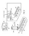
- FIG. 3is a schematic showing a mobile auxiliary station component of the present invention system shown in conjunction with the vehicle battery rack.
- the present invention systemcan be embodied in many ways, the embodiment illustrated shows the system having battery packs that can be selectively attached to a vehicle, a stationary power unit, and a portable power unit. These embodiments are selected in order to set forth the best modes contemplated for the invention. The illustrated embodiments, however, are merely exemplary and should not be considered a limitation when interpreting the scope of the appended claims.
- the vehicle 10can be an electric vehicle, a hybrid vehicle or a traditional gasoline powered vehicle.
- the vehicle 10contains a vehicle battery rack 12 that holds one or more portable battery packs 14 .
- the battery packs 14are designed to be both rapidly removed from the vehicle battery rack 12 and installed into the vehicle battery rack 12 , as will later be explained.
- Each battery pack 14preferably weights under twenty pounds so that it can be readily lifted by most any adult.
- Each battery pack 14also has an integral handle 16 that enables each battery pack 14 to be readily lifted by hand.
- Each battery pack 14preferably has enough cells to generate 12 volts DC when fully charged. However, battery packs that generate six or three volts can also be used, provided those battery packs are connected in series to produce 12 volts of direct current.
- the number of battery packs 14 present in the vehicle 10is dependent upon the operational requirements of the vehicle 10 . For example, if a vehicle 10 requires 1000 watts of power, and each battery pack 14 is rated at 200 Watts, it will be understood that at least five battery packs 14 are present in the vehicle battery rack 12 . In fact, it is preferred that the vehicle 10 have at least one more battery pack 14 than is required to operate the vehicle 10 . Consequently, using the same example, it will be understood that if the vehicle 10 requires 1000 Watts of power to operate, at least six 200-Watt battery packs 14 would be supplied in the vehicle battery rack 12 . In this manner, at least one of the battery packs 14 could be removed from the vehicle battery rack 12 and the vehicle 10 would still have the electrical power it needs to properly operate.
- the vehicle 10recharges the battery packs 14 on the vehicle battery rack 12 as the vehicle 10 operates.
- a traditional vehiclerecharges its battery using an alternator 15 that is turned by the engine.
- Such a recharging systemcan be used as part of the preset invention.
- secondary recharging mechanism 20also be present within the vehicle 10 .
- the secondary recharging mechanism 20may include reactive brake recharging system 21 that generate electricity when the brakes of the vehicle 10 are applied.
- the secondary recharging mechanism 20can also employ at least one solar panel 22 that can trickle charge the battery packs 14 , even when the vehicle 10 is at rest.
- the preferred secondary recharging mechanism 20is at least one wind turbine 23 .
- Each wind turbine 23is mounted to the vehicle 10 .
- the wind turbine 23can be under the hood of the vehicle 10 , on the roof of the vehicle 10 , on the sides of the vehicle 10 , or at any other position that receives an unobstructed flow of air as the vehicle 10 travels at speed.
- the wind turbine 23spins and generates electricity at a rate that is directly proportional to the speed that the vehicle 10 is traveling. In this manner, when the vehicle 10 is traveling at highway speeds in top gear and is efficiently using gasoline, the battery packs 14 are rapidly charged in a fuel efficient manner.
- the electrical power in the battery packs 14can be used to power the electrical systems of the vehicle 10 .
- the vehicle 10reaches its destination while the battery packs 14 are fully charged.
- each battery pack 14has a housing 24 .
- the housing 24connects to the vehicle battery rack 12 in the vehicle 10 using quick-connect mechanical fasteners 26 , such as latches.
- Each battery pack 14also has a connector 28 with electrodes that automatically interconnect with the vehicle battery rack 12 when the battery pack 14 is attached to the vehicle battery rack 12 .
- the electrodes of the connector 28disconnect and the battery pack 14 becomes electrically isolated.
- the first auxiliary battery rack 30is part of a stationary power unit 32 that is connected to the electrical circuitry 34 of a building 36 , such as a home, shed or vacation cabin.
- the first auxiliary battery rack 30is capable of holding multiple battery packs 14 .
- the first auxiliary power rack 30is connected to a power inverter 38 that converts the direct current of the battery packs 14 into the 60 Hz AC used to power buildings in North America.
- the AC poweris then fed through a supply switch 37 to the circuit breaker box 39 of the building 36 .
- the supply switch 37switches the incoming power source between the AC power from any incoming power company grid and the electrical power from the first auxiliary battery rack 30 .
- the supply switch 37need not be used if the building 36 is solely dependent upon the first auxiliary power rack 30 for its electrical power needs.
- the DC power stored in the battery packs 14 of the vehicle 10can be easily transferred into the AC power of a building 36 simply by manually moving one or more battery packs 14 from the vehicle battery rack 12 in the vehicle 10 to a first auxiliary battery rack 30 in a building 36 .
- a good application for the present invention systemwould be a vacation cabin that a person may use only a few weeks out of the year.
- a personcan place battery packs 14 in the vehicle battery rack 12 of the vehicle 10 and fully charge those battery packs 14 on the drive to the vacation cabin. Once at the vacation cabin, the fully charged battery packs 14 can be removed from the vehicle 10 and used to supply the AC power requirements of the vacation cabin.
- the battery packs 14can be returned to the vehicle 10 and recharged by running the vehicle 10 . It will be understood that one or more of the battery packs 14 can be set into the first auxiliary battery rack 30 at the same time, depending upon the electrical needs of the vacation cabin.
- the first auxiliary battery rack 30 and stationary power unit 32can be used in reverse to charge the battery packs 14 .
- the stationary power unit 32is supplied with a charger 33 . If the building 36 has a solar panel or is connected to a gasoline generator, the charger 33 can be used to charge the battery packs 14 placed in the first auxiliary battery rack 30 . In this manner, the stationary power unit 32 can be used to charge the battery packs 14 for later use by either the building 36 or the vehicle 10 .
- a second auxiliary battery rack 40is shown in FIG. 3 .
- the second auxiliary power rack 40is part of a portable electrical supply unit 42 .
- the portable electrical supply unit 42has a wheeled cart 44 that enables the portable electrical supply unit 42 to be easily moved from point to point.
- the second auxiliary power rack 40is also capable of holding one or more of the battery packs 14 .
- a power inverter 46is supplied that converts the DC power of the battery packs 14 to the 60 Hz AC power, used in the power grid of North America.
- the inverter 46is connected to one or more plug receptacles 48 . Accordingly, the plug receptacles 48 are powered with AC power at 60 Hz.
- the portable power unit 42is used in place of a portable generator.
- the wheeled cart 44is rolled up to a vehicle 10 having charged battery packs 14 .
- One or more charged battery packs 14are then transferred from the vehicle battery rack 12 in the vehicle 10 to the second auxiliary battery rack 40 in the wheeled cart 44 .
- the wheeled cart 44can be moved to any desired location. Any standard electrical appliance can then be plugged into the portable power unit 42 .
- a construction workercan utilize the portable power unit 42 to run power tools at a jobsite that does not otherwise have electricity.
- the portable power unit 42can also be used in reverse.
- a charger 50is provided on the wheeled cart 44 , as is an external plug 52 .
- the plug 52can be connected to any available power source, such as a power outlet in a garage. Once plugged in, the charger 50 charges the battery packs 14 . Once fully charged, the battery packs 14 can be returned to the vehicle 10 for use within the vehicle 10 . It will therefore be understood that the present invention system enables battery packs 14 from an electric vehicle or hybrid vehicle to be removed from the vehicle and remotely charged. This eliminates the need for the vehicle 10 to be parked near a power source. It also eliminates the need for a vehicle owner to run extension cords to a vehicle 10 .
- a solar panel 60can be attached to the portable power unit 42 to trickle charge the batter packs 14 .
- the solar panel 60can be replaced with any other available power source, such as a wind turbine or a traditional gasoline generator.
Landscapes
- Engineering & Computer Science (AREA)
- Power Engineering (AREA)
- Transportation (AREA)
- Mechanical Engineering (AREA)
- Life Sciences & Earth Sciences (AREA)
- Sustainable Development (AREA)
- Sustainable Energy (AREA)
- Business, Economics & Management (AREA)
- Emergency Management (AREA)
- Charge And Discharge Circuits For Batteries Or The Like (AREA)
- Electric Propulsion And Braking For Vehicles (AREA)
Abstract
Description
Claims (12)
Priority Applications (1)
| Application Number | Priority Date | Filing Date | Title |
|---|---|---|---|
| US13/271,204US8816534B1 (en) | 2011-10-11 | 2011-10-11 | System and method for generating, storing and transferring electrical power between a vehicle and an auxiliary application |
Applications Claiming Priority (1)
| Application Number | Priority Date | Filing Date | Title |
|---|---|---|---|
| US13/271,204US8816534B1 (en) | 2011-10-11 | 2011-10-11 | System and method for generating, storing and transferring electrical power between a vehicle and an auxiliary application |
Publications (1)
| Publication Number | Publication Date |
|---|---|
| US8816534B1true US8816534B1 (en) | 2014-08-26 |
Family
ID=51358532
Family Applications (1)
| Application Number | Title | Priority Date | Filing Date |
|---|---|---|---|
| US13/271,204Expired - Fee RelatedUS8816534B1 (en) | 2011-10-11 | 2011-10-11 | System and method for generating, storing and transferring electrical power between a vehicle and an auxiliary application |
Country Status (1)
| Country | Link |
|---|---|
| US (1) | US8816534B1 (en) |
Cited By (9)
| Publication number | Priority date | Publication date | Assignee | Title |
|---|---|---|---|---|
| US20150244305A1 (en)* | 2014-02-26 | 2015-08-27 | Francis Lugbenga Odubekun | BYOE_Bring Your OWN Enegi_Consumer Rechargeable Household Batteries_Pawabox-iPak |
| JP2016086514A (en)* | 2014-10-24 | 2016-05-19 | Jfeエンジニアリング株式会社 | Power supply system and waste disposal system |
| CN108032741A (en)* | 2017-10-24 | 2018-05-15 | 合肥成科电子科技有限公司 | A kind of electric automobile charging pile |
| CN108556663A (en)* | 2018-04-24 | 2018-09-21 | 宁波沸柴机器人科技有限公司 | A kind of lift solar recharging stake |
| US20190047432A1 (en)* | 2017-08-14 | 2019-02-14 | Sheila Clark | Secondary solar charging battery system for use with a recreational vehicle |
| US10709060B2 (en) | 2015-07-21 | 2020-07-14 | Husqvarna Ab | Lawn care vehicle with on board battery charging |
| US11081893B2 (en) | 2019-06-03 | 2021-08-03 | Toyota Motor Engineering & Manufacturing North America, Inc. | Removable high voltage battery components |
| WO2022047363A1 (en)* | 2020-08-31 | 2022-03-03 | Ecolution Kwh, Llc | Virtual power plant |
| CN114523875A (en)* | 2022-04-24 | 2022-05-24 | 杭州骏沃机电科技有限公司 | Battery storage rack and new energy automobile power changing station |
Citations (10)
| Publication number | Priority date | Publication date | Assignee | Title |
|---|---|---|---|---|
| US4977351A (en)* | 1986-11-18 | 1990-12-11 | Bavco Manufacturing Company, Inc. | Emergency lighting system |
| US5545967A (en)* | 1995-07-21 | 1996-08-13 | Precision Automation Systems, Inc. | Automatic battery management system |
| US5847537A (en)* | 1996-10-19 | 1998-12-08 | Parmley, Sr.; Daniel W. | Electric vehicle charging station system |
| US6653749B2 (en)* | 2000-12-22 | 2003-11-25 | Plug Power Inc. | Portable power supply system and a method for providing electrical power |
| US20070080586A1 (en)* | 2005-10-11 | 2007-04-12 | Busick Steven C | Emergency Battery Back-Up Power for Traffic Control Signals |
| US7661370B2 (en)* | 2005-10-19 | 2010-02-16 | Railpower, Llc | Design of a large low maintenance battery pack for a hybrid locomotive |
| US20110049992A1 (en)* | 2009-08-28 | 2011-03-03 | Sant Anselmo Robert | Systems, methods, and devices including modular, fixed and transportable structures incorporating solar and wind generation technologies for production of electricity |
| US20110221384A1 (en)* | 2006-02-09 | 2011-09-15 | Scheucher Karl F | Refuelable battery-powered electric vehicle |
| US8102076B2 (en)* | 2006-12-05 | 2012-01-24 | Enertek Solutions, Inc. | Daycab auxiliary power conversion apparatus |
| US8384244B2 (en)* | 2010-06-09 | 2013-02-26 | Microsoft Corporation | Rack-based uninterruptible power supply |
- 2011
- 2011-10-11USUS13/271,204patent/US8816534B1/ennot_activeExpired - Fee Related
Patent Citations (10)
| Publication number | Priority date | Publication date | Assignee | Title |
|---|---|---|---|---|
| US4977351A (en)* | 1986-11-18 | 1990-12-11 | Bavco Manufacturing Company, Inc. | Emergency lighting system |
| US5545967A (en)* | 1995-07-21 | 1996-08-13 | Precision Automation Systems, Inc. | Automatic battery management system |
| US5847537A (en)* | 1996-10-19 | 1998-12-08 | Parmley, Sr.; Daniel W. | Electric vehicle charging station system |
| US6653749B2 (en)* | 2000-12-22 | 2003-11-25 | Plug Power Inc. | Portable power supply system and a method for providing electrical power |
| US20070080586A1 (en)* | 2005-10-11 | 2007-04-12 | Busick Steven C | Emergency Battery Back-Up Power for Traffic Control Signals |
| US7661370B2 (en)* | 2005-10-19 | 2010-02-16 | Railpower, Llc | Design of a large low maintenance battery pack for a hybrid locomotive |
| US20110221384A1 (en)* | 2006-02-09 | 2011-09-15 | Scheucher Karl F | Refuelable battery-powered electric vehicle |
| US8102076B2 (en)* | 2006-12-05 | 2012-01-24 | Enertek Solutions, Inc. | Daycab auxiliary power conversion apparatus |
| US20110049992A1 (en)* | 2009-08-28 | 2011-03-03 | Sant Anselmo Robert | Systems, methods, and devices including modular, fixed and transportable structures incorporating solar and wind generation technologies for production of electricity |
| US8384244B2 (en)* | 2010-06-09 | 2013-02-26 | Microsoft Corporation | Rack-based uninterruptible power supply |
Cited By (10)
| Publication number | Priority date | Publication date | Assignee | Title |
|---|---|---|---|---|
| US20150244305A1 (en)* | 2014-02-26 | 2015-08-27 | Francis Lugbenga Odubekun | BYOE_Bring Your OWN Enegi_Consumer Rechargeable Household Batteries_Pawabox-iPak |
| JP2016086514A (en)* | 2014-10-24 | 2016-05-19 | Jfeエンジニアリング株式会社 | Power supply system and waste disposal system |
| US10709060B2 (en) | 2015-07-21 | 2020-07-14 | Husqvarna Ab | Lawn care vehicle with on board battery charging |
| US20190047432A1 (en)* | 2017-08-14 | 2019-02-14 | Sheila Clark | Secondary solar charging battery system for use with a recreational vehicle |
| CN108032741A (en)* | 2017-10-24 | 2018-05-15 | 合肥成科电子科技有限公司 | A kind of electric automobile charging pile |
| CN108556663A (en)* | 2018-04-24 | 2018-09-21 | 宁波沸柴机器人科技有限公司 | A kind of lift solar recharging stake |
| US11081893B2 (en) | 2019-06-03 | 2021-08-03 | Toyota Motor Engineering & Manufacturing North America, Inc. | Removable high voltage battery components |
| WO2022047363A1 (en)* | 2020-08-31 | 2022-03-03 | Ecolution Kwh, Llc | Virtual power plant |
| CN114523875A (en)* | 2022-04-24 | 2022-05-24 | 杭州骏沃机电科技有限公司 | Battery storage rack and new energy automobile power changing station |
| CN114523875B (en)* | 2022-04-24 | 2022-07-29 | 杭州骏沃机电科技有限公司 | Battery storage rack and new energy vehicle swap station |
Similar Documents
| Publication | Publication Date | Title |
|---|---|---|
| US8816534B1 (en) | System and method for generating, storing and transferring electrical power between a vehicle and an auxiliary application | |
| US20230231395A1 (en) | Battery system | |
| US10293698B2 (en) | System and method for powering electrified vehicle with modular battery | |
| CN101610932B (en) | Electric vehicle, vehicle charge device, and vehicle charge system | |
| US8922049B2 (en) | System for extracting electrical power from an electric vehicle | |
| US9013168B2 (en) | System for transferring energy from an energy source and method of making same | |
| Mohammadi | Design, analysis, and electrification of a solar-powered electric vehicle | |
| US20110080134A1 (en) | Apparatus with electric element sourced by a capacitive ceramic-based electrical energy storage unit (eesu) with storage charging from on-board electrical energy generation and external interface | |
| EP2301790A2 (en) | Electric scooter with on-board charging system | |
| Bansal | Electric vehicles | |
| CN103368222A (en) | Portable power systems | |
| US20150162814A1 (en) | Self-recharging electric generator system | |
| Becherif et al. | Design and sizing of a stand-alone recharging point for battery electrical vehicles using photovoltaic energy | |
| JP5510259B2 (en) | Vehicle power control device | |
| CN211556955U (en) | Energy storage device and relevant electric motor car that combine ultracapacitor system and battery package | |
| Gade | The new battery management system in electric vehicle | |
| Solomin et al. | Development of algorithms of rapid charging for batteries of hybrid and electric drives of city freight and passenger automobile transportation vehicles | |
| CN210123907U (en) | Power supply system of motor home | |
| Małek et al. | Urban logistics of small electric vehicle charged from a photovoltaic carport | |
| CN110474415A (en) | The energy storage device of a kind of combining super capacitor device and commutative battery pack and the electric vehicle driven with it | |
| WO2017143051A1 (en) | Electric vehicle charging system and methods of use | |
| CN103151476A (en) | Power supply module and electromobile provided with same | |
| CN223314842U (en) | Vehicle power supply system and vehicle | |
| US20240250552A1 (en) | A portable power unit | |
| Parvathy | Battery Charging Systems |
Legal Events
| Date | Code | Title | Description |
|---|---|---|---|
| STCF | Information on status: patent grant | Free format text:PATENTED CASE | |
| FEPP | Fee payment procedure | Free format text:MAINTENANCE FEE REMINDER MAILED (ORIGINAL EVENT CODE: REM.) | |
| FEPP | Fee payment procedure | Free format text:SURCHARGE FOR LATE PAYMENT, SMALL ENTITY (ORIGINAL EVENT CODE: M2554); ENTITY STATUS OF PATENT OWNER: SMALL ENTITY | |
| MAFP | Maintenance fee payment | Free format text:PAYMENT OF MAINTENANCE FEE, 4TH YR, SMALL ENTITY (ORIGINAL EVENT CODE: M2551); ENTITY STATUS OF PATENT OWNER: SMALL ENTITY Year of fee payment:4 | |
| FEPP | Fee payment procedure | Free format text:MAINTENANCE FEE REMINDER MAILED (ORIGINAL EVENT CODE: REM.); ENTITY STATUS OF PATENT OWNER: SMALL ENTITY | |
| LAPS | Lapse for failure to pay maintenance fees | Free format text:PATENT EXPIRED FOR FAILURE TO PAY MAINTENANCE FEES (ORIGINAL EVENT CODE: EXP.); ENTITY STATUS OF PATENT OWNER: SMALL ENTITY | |
| STCH | Information on status: patent discontinuation | Free format text:PATENT EXPIRED DUE TO NONPAYMENT OF MAINTENANCE FEES UNDER 37 CFR 1.362 | |
| FP | Lapsed due to failure to pay maintenance fee | Effective date:20220826 | |
| AS | Assignment | Owner name:ZIG ZAG INNOVATIONS, LLC, NEW JERSEY Free format text:ASSIGNMENT OF ASSIGNORS INTEREST;ASSIGNOR:VASQUEZ, RICARDO, MR;REEL/FRAME:063853/0063 Effective date:20170217 |