US8815197B2 - Method for urea decomposition and ammonia feed to a selective catalytic reduction system - Google Patents
Method for urea decomposition and ammonia feed to a selective catalytic reduction systemDownload PDFInfo
- Publication number
- US8815197B2 US8815197B2US14/047,737US201314047737AUS8815197B2US 8815197 B2US8815197 B2US 8815197B2US 201314047737 AUS201314047737 AUS 201314047737AUS 8815197 B2US8815197 B2US 8815197B2
- Authority
- US
- United States
- Prior art keywords
- injection
- urea
- duct
- continuous duct
- temperature
- Prior art date
- Legal status (The legal status is an assumption and is not a legal conclusion. Google has not performed a legal analysis and makes no representation as to the accuracy of the status listed.)
- Active
Links
- QGZKDVFQNNGYKY-UHFFFAOYSA-NAmmoniaChemical compoundNQGZKDVFQNNGYKY-UHFFFAOYSA-N0.000titleclaimsabstractdescription73
- 238000000354decomposition reactionMethods0.000titleclaimsabstractdescription50
- 238000000034methodMethods0.000titleclaimsabstractdescription32
- 229910021529ammoniaInorganic materials0.000titleclaimsabstractdescription24
- XSQUKJJJFZCRTK-UHFFFAOYSA-NUreaChemical compoundNC(N)=OXSQUKJJJFZCRTK-UHFFFAOYSA-N0.000titleclaimsdescription76
- 239000004202carbamideSubstances0.000titleclaimsdescription76
- 238000010531catalytic reduction reactionMethods0.000titledescription4
- 238000002347injectionMethods0.000claimsabstractdescription84
- 239000007924injectionSubstances0.000claimsabstractdescription84
- 239000003153chemical reaction reagentSubstances0.000claimsabstractdescription36
- 239000003054catalystSubstances0.000claimsabstractdescription30
- 238000002485combustion reactionMethods0.000claimsabstractdescription19
- 238000011144upstream manufacturingMethods0.000claimsabstractdescription13
- 239000007864aqueous solutionSubstances0.000claimsabstractdescription10
- 239000007789gasSubstances0.000claimsdescription59
- 239000003570airSubstances0.000claimsdescription18
- 239000000446fuelSubstances0.000claimsdescription13
- 230000009467reductionEffects0.000claimsdescription13
- 239000012080ambient airSubstances0.000claimsdescription12
- 239000000243solutionSubstances0.000claimsdescription11
- 230000000153supplemental effectEffects0.000claimsdescription7
- 239000012159carrier gasSubstances0.000claimsdescription6
- 238000001816coolingMethods0.000claimsdescription5
- 230000001105regulatory effectEffects0.000claimsdescription4
- 238000001704evaporationMethods0.000claimsdescription2
- 230000008020evaporationEffects0.000claimsdescription2
- 238000000889atomisationMethods0.000claims1
- MWUXSHHQAYIFBG-UHFFFAOYSA-NNitric oxideChemical compoundO=[N]MWUXSHHQAYIFBG-UHFFFAOYSA-N0.000description105
- 239000003546flue gasSubstances0.000description13
- 238000006722reduction reactionMethods0.000description12
- VHUUQVKOLVNVRT-UHFFFAOYSA-NAmmonium hydroxideChemical compound[NH4+].[OH-]VHUUQVKOLVNVRT-UHFFFAOYSA-N0.000description11
- UGFAIRIUMAVXCW-UHFFFAOYSA-NCarbon monoxideChemical compound[O+]#[C-]UGFAIRIUMAVXCW-UHFFFAOYSA-N0.000description11
- 235000011114ammonium hydroxideNutrition0.000description11
- 238000002309gasificationMethods0.000description8
- 239000006200vaporizerSubstances0.000description8
- XLYOFNOQVPJJNP-UHFFFAOYSA-NwaterSubstancesOXLYOFNOQVPJJNP-UHFFFAOYSA-N0.000description6
- 230000008569processEffects0.000description5
- 238000000197pyrolysisMethods0.000description5
- 239000007787solidSubstances0.000description4
- 238000012546transferMethods0.000description4
- 239000000567combustion gasSubstances0.000description3
- 238000013461designMethods0.000description3
- 238000002156mixingMethods0.000description3
- 239000002243precursorSubstances0.000description3
- 230000007704transitionEffects0.000description3
- 230000008016vaporizationEffects0.000description3
- IJGRMHOSHXDMSA-UHFFFAOYSA-NAtomic nitrogenChemical compoundN#NIJGRMHOSHXDMSA-UHFFFAOYSA-N0.000description2
- 239000006227byproductSubstances0.000description2
- 238000006243chemical reactionMethods0.000description2
- 230000000694effectsEffects0.000description2
- 239000012530fluidSubstances0.000description2
- 239000000383hazardous chemicalSubstances0.000description2
- VNWKTOKETHGBQD-UHFFFAOYSA-NmethaneChemical compoundCVNWKTOKETHGBQD-UHFFFAOYSA-N0.000description2
- 239000000203mixtureSubstances0.000description2
- 239000000047productSubstances0.000description2
- 239000007921spraySubstances0.000description2
- 238000009834vaporizationMethods0.000description2
- NLXLAEXVIDQMFP-UHFFFAOYSA-NAmmonium chlorideSubstances[NH4+].[Cl-]NLXLAEXVIDQMFP-UHFFFAOYSA-N0.000description1
- 238000013459approachMethods0.000description1
- 230000008901benefitEffects0.000description1
- 230000015572biosynthetic processEffects0.000description1
- 229910002091carbon monoxideInorganic materials0.000description1
- 239000003638chemical reducing agentSubstances0.000description1
- 230000003750conditioning effectEffects0.000description1
- 238000010276constructionMethods0.000description1
- 230000002596correlated effectEffects0.000description1
- 230000008878couplingEffects0.000description1
- 238000010168coupling processMethods0.000description1
- 238000005859coupling reactionMethods0.000description1
- 230000008021depositionEffects0.000description1
- 230000005611electricityEffects0.000description1
- 239000000839emulsionSubstances0.000description1
- 239000003344environmental pollutantSubstances0.000description1
- 238000000605extractionMethods0.000description1
- 238000009472formulationMethods0.000description1
- 229930195733hydrocarbonNatural products0.000description1
- 150000002430hydrocarbonsChemical class0.000description1
- 239000007788liquidSubstances0.000description1
- 238000013507mappingMethods0.000description1
- 239000000463materialSubstances0.000description1
- 239000002609mediumSubstances0.000description1
- 238000012986modificationMethods0.000description1
- 230000004048modificationEffects0.000description1
- 239000003345natural gasSubstances0.000description1
- 229910052757nitrogenInorganic materials0.000description1
- 231100000719pollutantToxicity0.000description1
- 238000010248power generationMethods0.000description1
- 238000005086pumpingMethods0.000description1
- 238000013341scale-upMethods0.000description1
- 239000004449solid propellantSubstances0.000description1
- 239000000126substanceSubstances0.000description1
- 239000006163transport mediaSubstances0.000description1
- 229910052720vanadiumInorganic materials0.000description1
- LEONUFNNVUYDNQ-UHFFFAOYSA-Nvanadium atomChemical compound[V]LEONUFNNVUYDNQ-UHFFFAOYSA-N0.000description1
- 239000002912waste gasSubstances0.000description1
Images


Classifications
- B—PERFORMING OPERATIONS; TRANSPORTING
- B01—PHYSICAL OR CHEMICAL PROCESSES OR APPARATUS IN GENERAL
- B01D—SEPARATION
- B01D53/00—Separation of gases or vapours; Recovering vapours of volatile solvents from gases; Chemical or biological purification of waste gases, e.g. engine exhaust gases, smoke, fumes, flue gases, aerosols
- B01D53/34—Chemical or biological purification of waste gases
- B01D53/46—Removing components of defined structure
- B01D53/54—Nitrogen compounds
- B01D53/56—Nitrogen oxides
- B01D53/565—Nitrogen oxides by treating the gases with solids
- B—PERFORMING OPERATIONS; TRANSPORTING
- B01—PHYSICAL OR CHEMICAL PROCESSES OR APPARATUS IN GENERAL
- B01D—SEPARATION
- B01D53/00—Separation of gases or vapours; Recovering vapours of volatile solvents from gases; Chemical or biological purification of waste gases, e.g. engine exhaust gases, smoke, fumes, flue gases, aerosols
- B01D53/34—Chemical or biological purification of waste gases
- B01D53/74—General processes for purification of waste gases; Apparatus or devices specially adapted therefor
- B01D53/86—Catalytic processes
- B01D53/8621—Removing nitrogen compounds
- B01D53/8625—Nitrogen oxides
- B01D53/8631—Processes characterised by a specific device
- B—PERFORMING OPERATIONS; TRANSPORTING
- B01—PHYSICAL OR CHEMICAL PROCESSES OR APPARATUS IN GENERAL
- B01D—SEPARATION
- B01D53/00—Separation of gases or vapours; Recovering vapours of volatile solvents from gases; Chemical or biological purification of waste gases, e.g. engine exhaust gases, smoke, fumes, flue gases, aerosols
- B01D53/34—Chemical or biological purification of waste gases
- B01D53/74—General processes for purification of waste gases; Apparatus or devices specially adapted therefor
- B01D53/86—Catalytic processes
- B01D53/90—Injecting reactants
- B—PERFORMING OPERATIONS; TRANSPORTING
- B01—PHYSICAL OR CHEMICAL PROCESSES OR APPARATUS IN GENERAL
- B01D—SEPARATION
- B01D2251/00—Reactants
- B01D2251/20—Reductants
- B01D2251/206—Ammonium compounds
- B01D2251/2067—Urea
Definitions
- the present inventionrelates generally to the reduction of nitrogen oxide (NOx) emissions from small industrial, commercial and electric utility boilers and other lean burn stationary combustion sources. More particularly, the present invention relates to a system and method in which urea is converted to ammonia for use in NOx reduction by selective catalytic reduction (SCR).
- SCRselective catalytic reduction
- NOxnitrogen oxide
- Primary measuressuch as low NOx burners, flue gas recirculation, fuel staging or air staging, need to balance the impact on the efficiency and stability of combustion with the level of NOx reduction obtained and the risk of increases in other regulated pollutants, such as carbon monoxide or unburned hydrocarbons.
- Secondary measuresincluding selective non catalytic reduction (SNCR) and selective catalytic reduction (SCR), involve the injection of reagents, such as ammonia or urea, into the upper furnace or the flue gases to chemically convert NOx to elemental nitrogen.
- Ammonia reagentis regulated as a hazardous substance, which has driven many end users to consider aqueous urea reagent as an alternative. While aqueous urea is not a hazardous substance, its application for NOx reduction requires additional design effort to make certain that the urea is fully gasified and does not leave intermediate solid by products which can foul surfaces and reduce chemical utilization.
- ureaIn converting urea to ammonia for use in NOx reduction by SCR, the art generally teaches the injection of urea into a heated vaporizer or a flowing side stream of hot combustion gases and/or heated air to gasify the urea for subsequent distribution upstream of a NOx reduction catalyst.
- Yamaguchiin U.S. Pat. No. 5,282,355, describes the prior art as using NOx free exhaust extracted by an exhaust gas recirculation fan to vaporize aqueous ammonia in a vaporizer from which it is injected into the flue upstream of a catalyst layer via an ammonia vapor pipe. He identifies aqueous urea as a precursor to aqueous ammonia which can also be vaporized by NOx free exhaust.
- Yamaguchisuggests that 0.5-1.0 seconds are required to vaporize the ammonia solution and Yamaguchi does not address the time required for complete decomposition and gasification of an aqueous solution of urea.
- Yamaguchiidentifies concerns about the formation and deposition of solids from the reaction of ammonia with other exhaust gas species and so proposes using superheated steam from the boiler or other source to provide the heat to vaporize the aqueous ammonia or its precursor in a vaporizer.
- the use of steam from a boilerhas a penalty associated with removing steam from the heat or power generation process and also with the cost of preparing de mineralized boiler makeup water to replace the steam used in the vaporization of the aqueous ammonia or its precursor.
- Peter-Hoblyn et al.in U.S. Pat. No. 5,809,774, describe the use of SCR for NOx reduction from lean burn engines in conjunction with fuel treatment using oil and water emulsions for a portion of the NOx reduction.
- Peter-Hoblyn et al.suggest that for SCR, especially at high loads, it is sometimes practical to introduce the aqueous solution of NOx reducing reagent into a slip stream (less than all, e.g., 5-25%) of the exhaust gases to achieve gasification of the reagent prior to mixing with the major or entire portion of exhaust gases.
- Peter-Hoblyn et alteach that the injection of aqueous urea into a pyrolysis chamber with droplets of under 500 micron, and preferably under 100 micron, will facilitate complete gasification of urea prior to introduction into the exhaust gases and allow close coupling of the pyrolysis chamber and SCR catalyst.
- the use of a return flow injectoris proposed to cool the injector and prevent solids from plugging the injector.
- Peter-Hoblyn et al.do not describe how to prevent plugging of the compact pyrolysis chamber with urea decomposition products, especially at higher urea injection rates. Additionally, it is difficult to see how complete gasification of urea is accomplished in the pyrolysis chamber described by Peter-Hoblyn et al. While the process of Peter-Hoblyn et al. may work for low urea injection rates on the order of 10-25 grams/minute as required for passenger car diesel engines, it is not apparent how this approach would scale up for higher injection rates of 50-1000 grams/minute or greater, as often required for small stationary combustion sources.
- Cho et al.in U.S. Pat. No. 5,296,206, describe the prior art as teaching the use of a flue gas slip stream drawn by a blower into a vaporizer vessel where the flue gas mixes and vaporizes aqueous ammonia, and also describes the use of an electric heater to heat ambient air and mix it with aqueous ammonia in a vessel, thus vaporizing the aqueous ammonia.
- Cho et al.identify both aqueous ammonia and urea as known reducing agents.
- Cho et al.propose using a heat exchanger in the flue gas to transfer heat to a heat transfer medium, such as ambient air, which is heated to 400° F.-950° F.
- Sun et al.in U.S. Pat. Nos. 7,090,810 and 7,829,033, describe a process for reducing NOx from a large-scale combustor involving a side stream of gases or heated ambient air into which urea is injected for decomposition and then introducing the side stream into a primary stream for NOx reduction across a catalyst.
- Sun et alspecifically teach that residence times of 1-10 seconds are required to effectively evaporate the water and gasify the urea such that solid byproducts do not foul the distribution pipes, ammonia injection grid (“AIG”) or catalyst or heat transfer surfaces. Supplemental heat from a burner, steam coil heater or other source can be utilized.
- AIGammonia injection grid
- Supplemental heat from a burner, steam coil heater or other sourcecan be utilized.
- Fuel Tech Inc.has commercially marketed a system called the ULTRATM process which generally uses a burner to decompose large quantities of urea to ammonia for large-scale combustors and a related product called ULTRA-5TM for smaller applications which uses an electric heater to heat ambient air for urea conversion. In many applications, a burner requires an additional permit to operate.
- the use of ambient temperature atomizing air for the air atomized injector of the Fuel Tech processescan represent as much as 8% of the overall air through the decomposition chamber. That cooler air combined with the cooling effect of introducing aqueous urea into the decomposition chamber can result in an outlet temperature from the decomposition chamber that is under 600° F. and well below the minimum 650° F.-700° F. outlet temperature range which Applicants have found to be desirable. That can lead to incomplete decomposition of urea and/or to the need for the longer residence times as proposed by Sun et al.
- the present inventionprovides a means and an apparatus that controls the rate of gas flow through the decomposition duct, maintains temperature in the duct, precisely controls the urea injection rate as a function of boiler load, targets and maintains urea spray quality without additional ambient atomizing aft and reduces the residence time requirement for evaporation and gasification to under 1 second while minimizing the need for external power.
- the present inventionis directed to small combustion sources, such as those used in commercial and industrial boiler, furnace and combustion turbine applications generally rated at 10 million to 350 million BTU/hr heat input. It utilizes a blower or fan coupled to the boiler or combustor exhaust from which a slipstream of hot exhaust gas is extracted generally at 300° F.-750° F. and up to 950° F.
- cooling air, water injection or cooler downstream exhaust gascan be added to the slipstream to lower the gas temperature to the blower to less than 750° F. This reduces the cost of blower materials of construction and improves blower reliability.
- a supplemental electric heater or burneris disposed in the slip stream portion of a duct following the blower and a temperature sensor is linked to the heater to maintain a gas temperature in the duct before the point of urea injection of at least 750° F.
- the sensoris located after the point of injection and used to adjust the heater to maintain at least 650° F. after the injection point.
- the slip stream portion of the continuous ductleads to an injection portion of the duct followed by a urea decomposition portion of the duct which is typically a simple expanded section of round duct of 4-12′′ diameter and up to 24-36′′ diameter depending on the quantity of reagent to be injected.
- the ductcan be insulated to retain heat.
- a gas swirlercan be positioned in the of the injection portion of the continuous duct prior to the urea injection point to create turbulence and mixing of the injected reagent in the gas stream.
- a smaller diameter slip stream portion of the ductis abruptly expanded into a larger diameter injection portion of the duct to create turbulence, high velocity and mixing past the point of aqueous urea injection.
- aqueous solution of 25-50% urea based reagent, or alternatively aqueous ammoniais sprayed into the injection portion of the duct.
- a single fluid return flow injector producing an average droplet size of less than 60 micronsis used to precisely control the reagent injection rate into the injection portion of the duct as a function of boiler load, exhaust gas flow rate or fuel feed rate which are correlated to uncontrolled boiler NOx emissions. Mapping with a hand held emissions monitor can be used to establish the NOx concentration in the exhaust gas versus combustor load, gas flow rate or fuel feed rate, or sensors can be used to monitor inlet and/or outlet NOx concentration and to adjust the urea injection rate to achieve the NOx reduction required.
- the urea injection rate into the injection portion of the ductis programmed into a programmable logic controller (PLC) along with a boiler load signal, fuel flow rate, steam flow rate, exhaust gas flow rate, and/or NOx or ammonia slip signal to adjust the injection rate.
- PLCprogrammable logic controller
- the PLCcontrols the pulse width or on-time of the valve in the solenoid actuated injector which regulates the rate of urea injection.
- a pumping skid with urea circulation pump, urea pressure sensor, urea filter and optional flow metersis used to circulate urea solution to and from the injector and is controlled by the PLC.
- a urea day tank with a solenoid valve, level sensor and optional transfer pumpcan be used to supply urea solution to the injection pump and be automatically controlled by the PLC to refill from bulk storage when the day tank level falls below a set point.
- Multiple injectorscan be used on the injection duct depending on the urea injection quantity required and the level of redundancy desired.
- Solenoid actuated return flow injectors of the kind described in U.S. Pat. No. 7,467,749 to Tarabulski et al.can be employed, as well as non-return flow solenoid valves, mechanical atomizers or air assisted injectors. It has surprisingly been found that small amounts of urea reagent such as that needed for small combustors can be easily gasified at temperatures of 750 F. and above measured upstream of the urea injection point with residence times of under 1 second if sufficient heated transport air and/or flue gas is available through the urea decomposition duct section to maintain an outlet temperature from the decomposition duct of at least 650° F. and preferably 700° F. and greater.
- Transport air rates of 150 scfm to 1500 scfm and up to 3000 scfmare generally adequate for decomposition of 0.5-10 gallons/hr of 32% urea in under 1 second residence if the air or flue gas is heated to 750° F. or above prior to the decomposition chamber.
- Residence time for decompositionis measured from the point of aqueous urea injection in the injection portion of the duct to the point of gasified reagent injection into the primary gas stream upstream of the SCR catalyst.
- an exhaust gas slipstreamas a transport medium helps reduce the cost of supplemental power for a heater or fuel for a burner, although ambient air or preheated air can also be used.
- An exhaust gas slipstream from a natural gas fired combustoris ideal in that it does not contain particulates from combustion.
- the exhaust gas slipstreambe filtered to reduce particulates through the decomposition duct and ammonia injection grid (“AIG”).
- Ammonia gas that is generated from the urea decomposition in the decomposition portion of the ductis ducted to an ammonia injection grid (“AIG”) designed for good distribution of gasified reagent in the primary exhaust gas stream upstream of the SCR catalyst.
- AIG designis well known to those skilled in the art, and therefore is not set out in detail herein.
- the AIGcan comprise, for example, simple vertical distribution pipes connected by a distribution header to the outlet of the urea decomposition portion of the duct and suspended from the top of a horizontal flowing primary exhaust duct or can comprise horizontal distribution pipes across a vertical flowing primary exhaust duct or other configurations of distribution pipes can be used.
- Each distribution pipetypically has multiple discharge orifices to achieve good ammonia distribution across the catalyst.
- a perforated plate or other flow conditioning devicescan be installed prior to or downstream of the AIG.
- Typical slip stream gas flow rates for good distribution through the AIGrepresent 0.2%-2% of the total exhaust gas flow, although the slip stream of hot carrier gases through the continuous duct can be as high as 10-50% of the total exhaust on combustion units with high baseline NOx levels requiring high reagent injection rates.
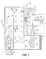
- FIG. 1is a schematic cross-sectional view of the present invention.
- FIG. 2is a schematic cross-sectional view of a first alternative embodiment of the present invention.
- FIG. 3is a schematic cross-sectional view of a second alternative embodiment of the present invention.
- FIG. 1illustrates a boiler configuration ( 10 ) wherein fuel and air are combusted by a burner ( 28 ) to form a flame ( 26 ) and hot combustion gases ( 20 ) which follow an exhaust path ( 58 ) past boiler tubes ( 46 ) where water through the tubes is converted to steam. Hot exhaust gases continue ( 60 ) and exit the boiler through an outlet transition ( 62 ).
- Ambient air (A)is drawn in through a fan ( 12 ) and ducted through a cold portion ( 22 ) of a continuous duct ( 14 ) to an electric heater ( 25 ) which heats the ambient air to a temperature of 700° F.-950° F.
- the heated air exiting the electric heaterthen passes through the hot portion ( 27 ) of the continuous duct ( 14 ) and through a transition portion ( 30 ) of the continuous duct ( 14 ) into an injection portion ( 18 ) of the continuous duct ( 14 ).
- Injector ( 36 )injects aqueous based urea reagent ( 32 ) stored in tank ( 34 ) into the injection portion ( 18 ) of the continuous duct ( 14 ) and flows with the hot carrier gas into the decomposition portion ( 33 ) of the continuous duct ( 14 ) where the water is evaporated and the reagent is decomposed to ammonia gas.
- the decomposed and gasified reagentis then ducted to an ammonia injection grid ( 37 ) and introduced into the primary exhaust gas ( 40 ) through the AIG lances ( 42 ) located upstream of catalyst ( 44 ).
- the ammonia gas introduced into the exhaustreacts with NOx across the catalyst ( 44 ) resulting in a reduction in emissions of NOx.
- Temperature sensor ( 35 )is used by the controller ( 56 ) to control the heater ( 25 ) so that the gas temperature in the decomposition portion ( 33 ) of the continuous duct ( 14 ) after the point of reagent injection is above 600° F. and preferably above 650° F. (i.e., some cooling of the gas, which is supplied to the injection portion ( 18 ) of the continuous duct ( 14 ) at a temperature of at least 700° F., may take place due to the injection of the reagent).
- Pump ( 54 )circulates reagent to injector ( 36 ) from storage tank ( 34 ) which holds aqueous based reagent ( 32 ).
- Controller ( 56 )controls the pump speed to maintain the pressure of the reagent delivered to the injector ( 36 ) and also controls the on time of the injector ( 36 ) to regulate the quantity of reagent injected as a function of one or more signals of the boiler load, fuel flow, inlet NOx, outlet NOx, gas flow or ammonia slip past the catalyst.
- the decomposition portion ( 33 ) of the continuous duct ( 14 )is sized to provide a residence time of less than 1 second and more typically between 0.2-0.6 seconds.
- the continuous duct ( 14 )has a circular cross section and the diameter of the injection portion ( 18 ) of the continuous duct ( 14 ) is between 0.2 and 2.5 times the diameter of the decomposition portion ( 33 ) of the continuous duct ( 14 ). In some cases the diameters of the injection portion ( 18 ) of the continuous duct ( 14 ) and the decomposition portion ( 33 ) of the continuous duct ( 14 ) are the same.
- the ratio between the injection portion ( 18 ) of the continuous duct ( 14 ) and the decomposition portion ( 33 ) of the continuous duct ( 14 )can also be measured by the cross-sectional area of the ducts.
- FIG. 2shows an arrangement very similar to that shown in FIG. 1 and like reference characters are used to designate like elements. However, the main difference between the embodiment shown in FIG. 2 and that shown in FIG. 1 is that the ambient air to the fan ( 12 ) of FIG. 1 is replaced with a hot exhaust gas drawn off from the boiler exhaust via a conduit ( 70 ).
- the exhaust gas temperature at the take off pointis between 400° F. and 750° F. as it is delivered to the fan ( 12 ), and preferably, the exhaust gas is taken off from the boiler after the heat exchanger section thereof, such that no heat exchanger is bypassed.
- the electric heater ( 25 )is then used, if necessary, to maintain a temperature of the gases supplied to the injection portion ( 18 ) of the continuous duct ( 14 ) of at least 700 F such that the temperature of the gas flowing in the decomposition portion ( 33 ) is at least 650° F. after injection of the reagent.
- FIG. 3again shows an arrangement very similar to that shown in FIG. 1 and like reference characters are used to designate like elements.
- electric heater ( 25 ) of FIG. 1is replaced with a separate heat exchanger loop ( 80 ) inserted into the boiler exhaust gas flow at ( 58 ), ( 60 ) or ( 62 ) and used to heat the ambient air from fan ( 12 ) to a temperature of at least 700° F. as it enters the transition to injection portion ( 18 ) of the continuous duct ( 14 ).
- the heat exchanger ( 80 )can be supplemented by a separate electric heater or burner.
- a slipstream of exhaust gas from a lean burn combustion engineis directed to an injection portion of a continuous duct.
- the slipstream flow rateis 300 scfm at a temperature of 700° F. to 750° F.
- the exhaust gas in the primary exhaust and in the slipstreamcontains 1100 ppm of NOx.
- the slipstreamis connected to an injection portion ( 18 ) and a decomposition portion ( 33 ) of a continuous duct ( 14 ) that is 5′′ in diameter.
- An aqueous solution of 32.5% ureais injected in the inlet end of the injection portion ( 18 ) of the continuous duct ( 14 ) using a solenoid actuated return flow injector as described in U.S. Pat. No.
- a computer based TRIM-NOX® injection systemas commercially available through Combustion Components Associates Inc. with an injection pump, filter, day tank, pressure sensor and touch screen display is used to inject the aqueous reagent at a rate of 0.5 to 0.75 gallons/hr into the injection duct.
- the injection portion ( 18 ) and the decomposition portion ( 33 )form part of a continuous duct ( 14 ), the outlet of which is connected to an ammonia injection grid (AIG) ( 37 ).
- the AIG ( 37 )includes two injection lances ( 42 ) that are connected to the outlet of the decomposition portion ( 33 ) of the continuous duct ( 14 ).
- the AIG lances ( 42 )have multiple outlet ports to allow ammonia gas to escape from the lances.
- the AIG lancesare fixed in the inlet of a SCR catalyst reactor, upstream of the catalyst ( 44 ), such that ammonia gas generated through the decomposition of urea in the decomposition portion ( 33 ) of the continuous duct ( 14 ) is injected from the lance outlet ports into the flowing stream of the primary exhaust flowing through the catalyst.
- the catalyst ( 44 )is of a commercial vanadium type formulation on a honeycomb support designed to reduce NOx in the presence of ammonia.
- NOx out of the catalyst reactoris reduced from 1100 ppm to 100 ppm indicating the decomposition of the aqueous urea to ammonia gas through the decomposition duct is sufficient to reduce NOx in the primary exhaust gas as it passes through the catalyst.
- a fanis used to supply ambient air to a 60 Kw electric heater.
- the fan and heaterdeliver 300 scfm of air at a temperature of 700° F. to 750° F. to a 5′′ diameter continuous duct having an injection portion ( 18 ) and a decomposition portion ( 33 ).
- a 32.5% solution of aqueous urea reagentis injected into the injection portion ( 18 ) of the continuous duct ( 14 ) using a solenoid actuated return flow injector and system as described in Example 1.
- the outlet of the decomposition portion ( 33 ) of the continuous duct ( 14 )is connected to the AIG ( 37 ) and catalyst ( 44 ) arrangement as described in Example 1.
- the full exhaust flow from a lean burn combustion engineis passed through the catalyst reactor at a rate of 1100 scfm to 1200 scfm and a temperature of 750 F with a NOx concentration of 1100 ppm.
- Injection of 0.5 to 0.75 gph of aqueous solution into the injection portion ( 18 ) of the continuous duct ( 14 )reduces the NOx out of the SCR reactor to 100 ppm indicating that the urea reagent has successfully been converted to ammonia gas which is successfully reducing NOx through the catalyst ( 44 ).
Landscapes
- Engineering & Computer Science (AREA)
- Chemical & Material Sciences (AREA)
- Environmental & Geological Engineering (AREA)
- Health & Medical Sciences (AREA)
- Biomedical Technology (AREA)
- Analytical Chemistry (AREA)
- General Chemical & Material Sciences (AREA)
- Oil, Petroleum & Natural Gas (AREA)
- Chemical Kinetics & Catalysis (AREA)
- Exhaust Gas Treatment By Means Of Catalyst (AREA)
- Treating Waste Gases (AREA)
Abstract
Description
Claims (21)
Priority Applications (1)
| Application Number | Priority Date | Filing Date | Title |
|---|---|---|---|
| US14/047,737US8815197B2 (en) | 2012-10-05 | 2013-10-07 | Method for urea decomposition and ammonia feed to a selective catalytic reduction system |
Applications Claiming Priority (2)
| Application Number | Priority Date | Filing Date | Title |
|---|---|---|---|
| US201261710356P | 2012-10-05 | 2012-10-05 | |
| US14/047,737US8815197B2 (en) | 2012-10-05 | 2013-10-07 | Method for urea decomposition and ammonia feed to a selective catalytic reduction system |
Publications (2)
| Publication Number | Publication Date |
|---|---|
| US20140099248A1 US20140099248A1 (en) | 2014-04-10 |
| US8815197B2true US8815197B2 (en) | 2014-08-26 |
Family
ID=50432813
Family Applications (1)
| Application Number | Title | Priority Date | Filing Date |
|---|---|---|---|
| US14/047,737ActiveUS8815197B2 (en) | 2012-10-05 | 2013-10-07 | Method for urea decomposition and ammonia feed to a selective catalytic reduction system |
Country Status (1)
| Country | Link |
|---|---|
| US (1) | US8815197B2 (en) |
Cited By (7)
| Publication number | Priority date | Publication date | Assignee | Title |
|---|---|---|---|---|
| US20140134061A1 (en)* | 2012-11-12 | 2014-05-15 | R. Gifford Broderick | Urea Decomposition And Improved Scr Nox Reduction On Industrial And Small Utility Boilers |
| US9861934B2 (en) | 2014-06-04 | 2018-01-09 | Peerless Mfg.Co | Cyclonic injector and method for reagent gasification and decomposition in a hot gas stream |
| CN109999646A (en)* | 2019-05-23 | 2019-07-12 | 贾新华 | A kind of SNCR denitration system and method for denitration |
| CN110292848A (en)* | 2019-05-14 | 2019-10-01 | 广州特种承压设备检测研究院 | A kind of waste incinerator deacidification equipment and method based on CFD |
| US10844763B2 (en) | 2017-03-10 | 2020-11-24 | R. F. Macdonald Co. | Process for direct urea injection with selective catalytic reduction (SCR) for NOx reduction in hot gas streams and related systems and assemblies |
| US11027237B2 (en) | 2019-07-19 | 2021-06-08 | American Electric Power Company, Inc. | Direct injection of aqueous urea |
| US11208934B2 (en) | 2019-02-25 | 2021-12-28 | Cummins Emission Solutions Inc. | Systems and methods for mixing exhaust gas and reductant |
Families Citing this family (3)
| Publication number | Priority date | Publication date | Assignee | Title |
|---|---|---|---|---|
| DE112015006508T5 (en)* | 2015-05-01 | 2018-04-12 | Cummins Emission Solutions, Inc. | Automatic performance tuning for diesel exhaust fluid dosage unit |
| CN109453665A (en)* | 2018-10-16 | 2019-03-12 | 中国华电科工集团有限公司 | A kind of urea liquid pyrolysis installation and method applied to denitrating system |
| US11162404B2 (en)* | 2019-07-02 | 2021-11-02 | Cummins Emission Solutions Inc. | Systems and methods for converting shear flow into axial flow in an exhaust system |
Citations (16)
| Publication number | Priority date | Publication date | Assignee | Title |
|---|---|---|---|---|
| US5282355A (en) | 1991-09-02 | 1994-02-01 | Mitsubishi Jukogyo Kabushiki Kaisha | Exhaust gas NOx removal system |
| US5296206A (en) | 1992-07-31 | 1994-03-22 | Foster Wheeler Energy Corporation | Using flue gas energy to vaporize aqueous reducing agent for reduction of NOx in flue gas |
| US5809774A (en) | 1996-11-19 | 1998-09-22 | Clean Diesel Technologies, Inc. | System for fueling and feeding chemicals to internal combustion engines for NOx reduction |
| US5968464A (en) | 1997-05-12 | 1999-10-19 | Clean Diesel Technologies, Inc. | Urea pyrolysis chamber and process for reducing lean-burn engine NOx emissions by selective catalytic reduction |
| US20040191709A1 (en) | 2003-03-26 | 2004-09-30 | Miller Eric S. | Economizer bypass with ammonia injection |
| US20060115402A1 (en) | 2003-07-03 | 2006-06-01 | Fuel Tech, Inc. | SELECTIVE CATALYTIC REDUCTION OF NOx ENABLED BY SIDESTREAM UREA DECOMPOSITION |
| US7090810B2 (en) | 2000-12-01 | 2006-08-15 | Fuel Tech Inc. | Selective catalytic reduction of nox enabled by sidestream urea decomposition |
| US20060207243A1 (en) | 2002-05-07 | 2006-09-21 | Phillip Roberts | Emission control system |
| US20080070177A1 (en) | 2006-01-09 | 2008-03-20 | Hansen Eric R | METHOD AND APPARATUS FOR REDUCING NOx EMISSIONS IN ROTARY KILNS BY SNCR |
| US7467749B2 (en) | 2004-04-26 | 2008-12-23 | Tenneco Automotive Operating Company Inc. | Methods and apparatus for injecting atomized reagent |
| US20090274601A1 (en) | 2008-04-30 | 2009-11-05 | Yul Kwan | Method of reducing nitrogen oxides in a gas stream with vaporized ammonia |
| US7615200B2 (en) | 2000-12-01 | 2009-11-10 | Fuel Tech, Inc. | Selective catalytic reduction of NOx enabled by urea decomposition in heat-exchanger bypass |
| US20110133127A1 (en) | 2009-11-05 | 2011-06-09 | Johnson Matthey Inc. | system and method to gasify aqueous urea into ammonia vapors using secondary flue gases |
| US20110195007A1 (en) | 2008-05-16 | 2011-08-11 | Postech Academy-Industry Foundation | CATALYST FOR REMOVING NOx FROM EXHAUST GAS OF LEAN-BURNING AUTOMOBILES OR INCINERATORS |
| US20120177553A1 (en) | 2010-12-07 | 2012-07-12 | Lindemann Scott H | Injector And Method For Reducing Nox Emissions From Boilers, IC Engines and Combustion Processes |
| US8470277B2 (en)* | 2011-08-10 | 2013-06-25 | Fuel Tech, Inc. | Selective catalytic NOx reduction process and control system |
- 2013
- 2013-10-07USUS14/047,737patent/US8815197B2/enactiveActive
Patent Citations (20)
| Publication number | Priority date | Publication date | Assignee | Title |
|---|---|---|---|---|
| US5282355A (en) | 1991-09-02 | 1994-02-01 | Mitsubishi Jukogyo Kabushiki Kaisha | Exhaust gas NOx removal system |
| US5296206A (en) | 1992-07-31 | 1994-03-22 | Foster Wheeler Energy Corporation | Using flue gas energy to vaporize aqueous reducing agent for reduction of NOx in flue gas |
| US5809774A (en) | 1996-11-19 | 1998-09-22 | Clean Diesel Technologies, Inc. | System for fueling and feeding chemicals to internal combustion engines for NOx reduction |
| US5968464A (en) | 1997-05-12 | 1999-10-19 | Clean Diesel Technologies, Inc. | Urea pyrolysis chamber and process for reducing lean-burn engine NOx emissions by selective catalytic reduction |
| US6203770B1 (en) | 1997-05-12 | 2001-03-20 | Clean Diesel Technologies, Inc. | Urea pyrolysis chamber and process for reducing lean-burn engine NOx emissions by selective catalytic reduction |
| US7615200B2 (en) | 2000-12-01 | 2009-11-10 | Fuel Tech, Inc. | Selective catalytic reduction of NOx enabled by urea decomposition in heat-exchanger bypass |
| US7090810B2 (en) | 2000-12-01 | 2006-08-15 | Fuel Tech Inc. | Selective catalytic reduction of nox enabled by sidestream urea decomposition |
| US7815881B2 (en) | 2000-12-01 | 2010-10-19 | Fuel Tech, Inc. | Selective catalytic reduction of NOx enabled by urea decomposition heat-exchanger bypass |
| US20100055014A1 (en) | 2000-12-01 | 2010-03-04 | Fuel Tech, Inc. | Selective Catalytic Reduction of NOx Enabled by Urea Decomposition Heat-Exchanger Bypass |
| US20060207243A1 (en) | 2002-05-07 | 2006-09-21 | Phillip Roberts | Emission control system |
| US20040191709A1 (en) | 2003-03-26 | 2004-09-30 | Miller Eric S. | Economizer bypass with ammonia injection |
| US7829033B2 (en) | 2003-07-03 | 2010-11-09 | Fuel Tech, Inc. | Selective catalytic reduction of NOx enabled by sidestream urea decomposition |
| US20060115402A1 (en) | 2003-07-03 | 2006-06-01 | Fuel Tech, Inc. | SELECTIVE CATALYTIC REDUCTION OF NOx ENABLED BY SIDESTREAM UREA DECOMPOSITION |
| US7467749B2 (en) | 2004-04-26 | 2008-12-23 | Tenneco Automotive Operating Company Inc. | Methods and apparatus for injecting atomized reagent |
| US20080070177A1 (en) | 2006-01-09 | 2008-03-20 | Hansen Eric R | METHOD AND APPARATUS FOR REDUCING NOx EMISSIONS IN ROTARY KILNS BY SNCR |
| US20090274601A1 (en) | 2008-04-30 | 2009-11-05 | Yul Kwan | Method of reducing nitrogen oxides in a gas stream with vaporized ammonia |
| US20110195007A1 (en) | 2008-05-16 | 2011-08-11 | Postech Academy-Industry Foundation | CATALYST FOR REMOVING NOx FROM EXHAUST GAS OF LEAN-BURNING AUTOMOBILES OR INCINERATORS |
| US20110133127A1 (en) | 2009-11-05 | 2011-06-09 | Johnson Matthey Inc. | system and method to gasify aqueous urea into ammonia vapors using secondary flue gases |
| US20120177553A1 (en) | 2010-12-07 | 2012-07-12 | Lindemann Scott H | Injector And Method For Reducing Nox Emissions From Boilers, IC Engines and Combustion Processes |
| US8470277B2 (en)* | 2011-08-10 | 2013-06-25 | Fuel Tech, Inc. | Selective catalytic NOx reduction process and control system |
Non-Patent Citations (1)
| Title |
|---|
| International Search Report and Written Opinion of the International Searching Authority Application No. PCT/US2013/063446 Completed: Jan. 30, 2014; Mailing Date: Feb. 7, 2014 11 pages. |
Cited By (12)
| Publication number | Priority date | Publication date | Assignee | Title |
|---|---|---|---|---|
| US20140134061A1 (en)* | 2012-11-12 | 2014-05-15 | R. Gifford Broderick | Urea Decomposition And Improved Scr Nox Reduction On Industrial And Small Utility Boilers |
| US9746177B2 (en)* | 2012-11-12 | 2017-08-29 | Peerless Mfg. Co. | Urea decomposition and improved SCR NOx reduction on industrial and small utility boilers |
| US9861934B2 (en) | 2014-06-04 | 2018-01-09 | Peerless Mfg.Co | Cyclonic injector and method for reagent gasification and decomposition in a hot gas stream |
| US10583393B2 (en) | 2014-06-04 | 2020-03-10 | Ceco Environmental Ip Inc. | Cyclonic injector and method for reagent gasification and decomposition in a hot gas stream |
| US10844763B2 (en) | 2017-03-10 | 2020-11-24 | R. F. Macdonald Co. | Process for direct urea injection with selective catalytic reduction (SCR) for NOx reduction in hot gas streams and related systems and assemblies |
| US11242789B2 (en) | 2017-03-10 | 2022-02-08 | R. F. Macdonald Co. | Process for direct urea injection with selective catalytic reduction (SCR) for NOx reduction in hot gas streams and related systems and assemblies |
| US11208934B2 (en) | 2019-02-25 | 2021-12-28 | Cummins Emission Solutions Inc. | Systems and methods for mixing exhaust gas and reductant |
| CN110292848A (en)* | 2019-05-14 | 2019-10-01 | 广州特种承压设备检测研究院 | A kind of waste incinerator deacidification equipment and method based on CFD |
| CN110292848B (en)* | 2019-05-14 | 2021-10-01 | 广州特种承压设备检测研究院 | A CFD-based waste incinerator deacidification equipment and method |
| CN109999646A (en)* | 2019-05-23 | 2019-07-12 | 贾新华 | A kind of SNCR denitration system and method for denitration |
| CN109999646B (en)* | 2019-05-23 | 2021-06-01 | 贾新华 | SNCR (selective non-catalytic reduction) denitration system and denitration method |
| US11027237B2 (en) | 2019-07-19 | 2021-06-08 | American Electric Power Company, Inc. | Direct injection of aqueous urea |
Also Published As
| Publication number | Publication date |
|---|---|
| US20140099248A1 (en) | 2014-04-10 |
Similar Documents
| Publication | Publication Date | Title |
|---|---|---|
| US8815197B2 (en) | Method for urea decomposition and ammonia feed to a selective catalytic reduction system | |
| US9593609B2 (en) | System and method for urea decomposition to ammonia in a side stream for selective catalytic reduction | |
| US8591849B2 (en) | On demand generation of ammonia for small industrial and commercial boilers | |
| US5282355A (en) | Exhaust gas NOx removal system | |
| US10583393B2 (en) | Cyclonic injector and method for reagent gasification and decomposition in a hot gas stream | |
| KR100259104B1 (en) | Method of vaporizing an aqueous reducing agent for the reduction of nitrogen oxides in flue gas | |
| US20130152470A1 (en) | Injector and method for reducing nox emissions from boilers, ic engines and combustion processes | |
| CN107398176A (en) | Urea pyrolysis and spraying system for low-temperature smoke air SCR denitration | |
| US9649594B2 (en) | Dual injection grid arrangement | |
| US9255507B2 (en) | Reagent injection system for exhaust of turbine system | |
| CA2125753C (en) | Combined heat exchanger and ammonia injection process | |
| US20110005438A1 (en) | Method For The Selective Catalytic Reduction Of Nitrogen Oxides In Combustion Flue Gases And System For Implementing It | |
| CN102794106A (en) | Method and device for spraying reducing agent used for selective catalytic reduction (SCR) of NOx | |
| US7588440B2 (en) | Carrier air heating system for SCR | |
| CN104226109B (en) | The SCR denitration method of a kind of boiler built-in urea pyrolysis pipe and device thereof | |
| US8047145B2 (en) | Ammonia vaporization system using non-flue gas intermediate heat transfer medium | |
| JP4917208B2 (en) | Method and apparatus for supplying liquid reducing agent for denitration apparatus | |
| CN101928014A (en) | Process for producing ammonia from urea used for denitration of boiler smoke and system thereof | |
| CA2685555C (en) | A method for the conversion of urea to reactants for nox reduction | |
| US20150093315A1 (en) | Tunable AIG for Improved SCR Performance | |
| US9746177B2 (en) | Urea decomposition and improved SCR NOx reduction on industrial and small utility boilers | |
| CN207169430U (en) | Urea pyrolysis and spraying system for low-temperature smoke air SCR denitration | |
| CN207025089U (en) | A kind of ammonia system processed that urea pyrolysis is directly realized using high temperature flue-gas from boiler | |
| WO2014055858A1 (en) | Selective catalytic reduction system | |
| US20120051990A1 (en) | Exhaust gas cleaning apparatus and method for cleaning an exhaust gas |
Legal Events
| Date | Code | Title | Description |
|---|---|---|---|
| AS | Assignment | Owner name:COMBUSTION COMPONENTS ASSOCIATES, INC., CONNECTICU Free format text:ASSIGNMENT OF ASSIGNORS INTEREST;ASSIGNORS:BRODERICK, JEFFREY MICHAEL;LINDEMANN, SCOTT H.;VALENTINE, JAMES M.;REEL/FRAME:031649/0605 Effective date:20131021 | |
| AS | Assignment | Owner name:PEERLESS MFG. CO., TEXAS Free format text:ASSIGNMENT OF ASSIGNORS INTEREST;ASSIGNOR:COMBUSTION COMPONENTS ASSOCIATES, INC.;REEL/FRAME:032801/0550 Effective date:20140318 | |
| STCF | Information on status: patent grant | Free format text:PATENTED CASE | |
| AS | Assignment | Owner name:BANK OF AMERICA, N.A., AS ADMINISTRATIVE AGENT, TE Free format text:NOTICE OF GRANT OF SECURITY INTEREST IN PATENTS;ASSIGNOR:PEERLESS MFG. CO.;REEL/FRAME:036553/0940 Effective date:20150903 | |
| AS | Assignment | Owner name:BANK OF AMERICA, N.A., AS ADMINISTRATIVE AGENT, TE Free format text:CORRECTIVE ASSIGNMENT TO CORRECT THE INCORRECTLY RECORDED TO PATENT NO.:8571849 PREVIOUSLY RECORDED ON REEL 036553 FRAME 0940. ASSIGNOR(S) HEREBY CONFIRMS THE CORRECT PATENT NO. 8591849;ASSIGNOR:PEERLESS MFG. CO.;REEL/FRAME:037783/0850 Effective date:20150903 | |
| FEPP | Fee payment procedure | Free format text:MAINTENANCE FEE REMINDER MAILED (ORIGINAL EVENT CODE: REM.) | |
| FEPP | Fee payment procedure | Free format text:SURCHARGE FOR LATE PAYMENT, LARGE ENTITY (ORIGINAL EVENT CODE: M1554) | |
| MAFP | Maintenance fee payment | Free format text:PAYMENT OF MAINTENANCE FEE, 4TH YEAR, LARGE ENTITY (ORIGINAL EVENT CODE: M1551) Year of fee payment:4 | |
| AS | Assignment | Owner name:CECO ENVIRONMENTAL IP INC., TEXAS Free format text:ASSIGNMENT OF ASSIGNORS INTEREST;ASSIGNOR:PEERLESS MANUFACTURING COMPANY;REEL/FRAME:047623/0189 Effective date:20181114 | |
| MAFP | Maintenance fee payment | Free format text:PAYMENT OF MAINTENANCE FEE, 8TH YEAR, LARGE ENTITY (ORIGINAL EVENT CODE: M1552); ENTITY STATUS OF PATENT OWNER: LARGE ENTITY Year of fee payment:8 |