US8814914B2 - Fusion method and pedicle access tool - Google Patents
Fusion method and pedicle access toolDownload PDFInfo
- Publication number
- US8814914B2 US8814914B2US12/550,235US55023509AUS8814914B2US 8814914 B2US8814914 B2US 8814914B2US 55023509 AUS55023509 AUS 55023509AUS 8814914 B2US8814914 B2US 8814914B2
- Authority
- US
- United States
- Prior art keywords
- cannula
- bone
- vertebra
- promoting material
- rasp
- Prior art date
- Legal status (The legal status is an assumption and is not a legal conclusion. Google has not performed a legal analysis and makes no representation as to the accuracy of the status listed.)
- Active, expires
Links
Images


Classifications
- A—HUMAN NECESSITIES
- A61—MEDICAL OR VETERINARY SCIENCE; HYGIENE
- A61B—DIAGNOSIS; SURGERY; IDENTIFICATION
- A61B17/00—Surgical instruments, devices or methods
- A61B17/56—Surgical instruments or methods for treatment of bones or joints; Devices specially adapted therefor
- A61B17/58—Surgical instruments or methods for treatment of bones or joints; Devices specially adapted therefor for osteosynthesis, e.g. bone plates, screws or setting implements
- A61B17/88—Osteosynthesis instruments; Methods or means for implanting or extracting internal or external fixation devices
- A—HUMAN NECESSITIES
- A61—MEDICAL OR VETERINARY SCIENCE; HYGIENE
- A61B—DIAGNOSIS; SURGERY; IDENTIFICATION
- A61B17/00—Surgical instruments, devices or methods
- A61B17/16—Instruments for performing osteoclasis; Drills or chisels for bones; Trepans
- A61B17/1655—Instruments for performing osteoclasis; Drills or chisels for bones; Trepans for tapping
- A—HUMAN NECESSITIES
- A61—MEDICAL OR VETERINARY SCIENCE; HYGIENE
- A61B—DIAGNOSIS; SURGERY; IDENTIFICATION
- A61B17/00—Surgical instruments, devices or methods
- A61B17/16—Instruments for performing osteoclasis; Drills or chisels for bones; Trepans
- A61B17/1659—Surgical rasps, files, planes, or scrapers
- A—HUMAN NECESSITIES
- A61—MEDICAL OR VETERINARY SCIENCE; HYGIENE
- A61B—DIAGNOSIS; SURGERY; IDENTIFICATION
- A61B17/00—Surgical instruments, devices or methods
- A61B17/16—Instruments for performing osteoclasis; Drills or chisels for bones; Trepans
- A61B17/1662—Instruments for performing osteoclasis; Drills or chisels for bones; Trepans for particular parts of the body
- A61B17/1671—Instruments for performing osteoclasis; Drills or chisels for bones; Trepans for particular parts of the body for the spine
- A—HUMAN NECESSITIES
- A61—MEDICAL OR VETERINARY SCIENCE; HYGIENE
- A61B—DIAGNOSIS; SURGERY; IDENTIFICATION
- A61B17/00—Surgical instruments, devices or methods
- A61B17/16—Instruments for performing osteoclasis; Drills or chisels for bones; Trepans
- A61B17/17—Guides or aligning means for drills, mills, pins or wires
- A61B17/1739—Guides or aligning means for drills, mills, pins or wires specially adapted for particular parts of the body
- A61B17/1757—Guides or aligning means for drills, mills, pins or wires specially adapted for particular parts of the body for the spine
- A—HUMAN NECESSITIES
- A61—MEDICAL OR VETERINARY SCIENCE; HYGIENE
- A61B—DIAGNOSIS; SURGERY; IDENTIFICATION
- A61B17/00—Surgical instruments, devices or methods
- A61B17/34—Trocars; Puncturing needles
- A61B17/3472—Trocars; Puncturing needles for bones, e.g. intraosseus injections
- A—HUMAN NECESSITIES
- A61—MEDICAL OR VETERINARY SCIENCE; HYGIENE
- A61B—DIAGNOSIS; SURGERY; IDENTIFICATION
- A61B17/00—Surgical instruments, devices or methods
- A61B17/56—Surgical instruments or methods for treatment of bones or joints; Devices specially adapted therefor
- A61B17/58—Surgical instruments or methods for treatment of bones or joints; Devices specially adapted therefor for osteosynthesis, e.g. bone plates, screws or setting implements
- A61B17/68—Internal fixation devices, including fasteners and spinal fixators, even if a part thereof projects from the skin
- A61B17/70—Spinal positioners or stabilisers, e.g. stabilisers comprising fluid filler in an implant
- A61B17/7001—Screws or hooks combined with longitudinal elements which do not contact vertebrae
- A61B17/7044—Screws or hooks combined with longitudinal elements which do not contact vertebrae also having plates, staples or washers bearing on the vertebrae
- A—HUMAN NECESSITIES
- A61—MEDICAL OR VETERINARY SCIENCE; HYGIENE
- A61B—DIAGNOSIS; SURGERY; IDENTIFICATION
- A61B17/00—Surgical instruments, devices or methods
- A61B17/56—Surgical instruments or methods for treatment of bones or joints; Devices specially adapted therefor
- A61B17/58—Surgical instruments or methods for treatment of bones or joints; Devices specially adapted therefor for osteosynthesis, e.g. bone plates, screws or setting implements
- A61B17/88—Osteosynthesis instruments; Methods or means for implanting or extracting internal or external fixation devices
- A61B17/885—Tools for expanding or compacting bones or discs or cavities therein
- A—HUMAN NECESSITIES
- A61—MEDICAL OR VETERINARY SCIENCE; HYGIENE
- A61B—DIAGNOSIS; SURGERY; IDENTIFICATION
- A61B1/00—Instruments for performing medical examinations of the interior of cavities or tubes of the body by visual or photographical inspection, e.g. endoscopes; Illuminating arrangements therefor
- A61B1/32—Devices for opening or enlarging the visual field, e.g. of a tube of the body
- A—HUMAN NECESSITIES
- A61—MEDICAL OR VETERINARY SCIENCE; HYGIENE
- A61B—DIAGNOSIS; SURGERY; IDENTIFICATION
- A61B17/00—Surgical instruments, devices or methods
- A61B17/02—Surgical instruments, devices or methods for holding wounds open, e.g. retractors; Tractors
- A61B17/0218—Surgical instruments, devices or methods for holding wounds open, e.g. retractors; Tractors for minimally invasive surgery
- A—HUMAN NECESSITIES
- A61—MEDICAL OR VETERINARY SCIENCE; HYGIENE
- A61B—DIAGNOSIS; SURGERY; IDENTIFICATION
- A61B17/00—Surgical instruments, devices or methods
- A61B17/16—Instruments for performing osteoclasis; Drills or chisels for bones; Trepans
- A61B17/1604—Chisels; Rongeurs; Punches; Stamps
- A—HUMAN NECESSITIES
- A61—MEDICAL OR VETERINARY SCIENCE; HYGIENE
- A61B—DIAGNOSIS; SURGERY; IDENTIFICATION
- A61B17/00—Surgical instruments, devices or methods
- A61B17/56—Surgical instruments or methods for treatment of bones or joints; Devices specially adapted therefor
- A61B17/58—Surgical instruments or methods for treatment of bones or joints; Devices specially adapted therefor for osteosynthesis, e.g. bone plates, screws or setting implements
- A61B17/88—Osteosynthesis instruments; Methods or means for implanting or extracting internal or external fixation devices
- A61B17/8897—Guide wires or guide pins
- A—HUMAN NECESSITIES
- A61—MEDICAL OR VETERINARY SCIENCE; HYGIENE
- A61B—DIAGNOSIS; SURGERY; IDENTIFICATION
- A61B17/00—Surgical instruments, devices or methods
- A61B17/56—Surgical instruments or methods for treatment of bones or joints; Devices specially adapted therefor
- A61B17/58—Surgical instruments or methods for treatment of bones or joints; Devices specially adapted therefor for osteosynthesis, e.g. bone plates, screws or setting implements
- A61B17/88—Osteosynthesis instruments; Methods or means for implanting or extracting internal or external fixation devices
- A61B17/90—Guides therefor
- A61B2017/90—
- A—HUMAN NECESSITIES
- A61—MEDICAL OR VETERINARY SCIENCE; HYGIENE
- A61B—DIAGNOSIS; SURGERY; IDENTIFICATION
- A61B90/00—Instruments, implements or accessories specially adapted for surgery or diagnosis and not covered by any of the groups A61B1/00 - A61B50/00, e.g. for luxation treatment or for protecting wound edges
- A61B90/03—Automatic limiting or abutting means, e.g. for safety
- A61B2090/033—Abutting means, stops, e.g. abutting on tissue or skin
- A61B2090/036—Abutting means, stops, e.g. abutting on tissue or skin abutting on tissue or skin
- A—HUMAN NECESSITIES
- A61—MEDICAL OR VETERINARY SCIENCE; HYGIENE
- A61B—DIAGNOSIS; SURGERY; IDENTIFICATION
- A61B90/00—Instruments, implements or accessories specially adapted for surgery or diagnosis and not covered by any of the groups A61B1/00 - A61B50/00, e.g. for luxation treatment or for protecting wound edges
- A61B90/06—Measuring instruments not otherwise provided for
- A61B2090/062—Measuring instruments not otherwise provided for penetration depth
- A—HUMAN NECESSITIES
- A61—MEDICAL OR VETERINARY SCIENCE; HYGIENE
- A61F—FILTERS IMPLANTABLE INTO BLOOD VESSELS; PROSTHESES; DEVICES PROVIDING PATENCY TO, OR PREVENTING COLLAPSING OF, TUBULAR STRUCTURES OF THE BODY, e.g. STENTS; ORTHOPAEDIC, NURSING OR CONTRACEPTIVE DEVICES; FOMENTATION; TREATMENT OR PROTECTION OF EYES OR EARS; BANDAGES, DRESSINGS OR ABSORBENT PADS; FIRST-AID KITS
- A61F2/00—Filters implantable into blood vessels; Prostheses, i.e. artificial substitutes or replacements for parts of the body; Appliances for connecting them with the body; Devices providing patency to, or preventing collapsing of, tubular structures of the body, e.g. stents
- A61F2/02—Prostheses implantable into the body
- A61F2/30—Joints
- A61F2/46—Special tools for implanting artificial joints
- A61F2/4603—Special tools for implanting artificial joints for insertion or extraction of endoprosthetic joints or of accessories thereof
- A61F2/4611—Special tools for implanting artificial joints for insertion or extraction of endoprosthetic joints or of accessories thereof of spinal prostheses
Definitions
- the present disclosurerelates to spinal surgery tools and methods.
- embodiments described hereinrelate to a pedicle access tool and methods for performing spinal fusion procedures. Even more particularly, embodiments relate to posterolateral spinal fusion methods.
- bone graftis placed on the posterior side of the spine between the transverse processes of vertebrae.
- the graftpromotes bone growth between the vertebrae.
- the new boneWhen the new bone is fully formed it fuses two or more vertebrae together, increasing the stability of the spine.
- a targeting needlethat includes a stylet and cannula is advanced to a desired pedicle and tapped into the bone using a mallet.
- the targeting needleis at a desired depth, the stylet is removed leaving the cannula.
- a k-wireis guided down the cannula and inserted into the bone. Once the guide wire is in place, the cannula is removed.
- a series of dilatorsare used to distract tissue about the k-wire.
- a bone awlis passed over the k-wire and used to puncture through the cortical layer of the vertebra to create a hole not exceeding the depth of the k-wire.
- a tapis then guided over the k-wire to tap the hole formed by the bone awl. Once the tap is removed, the bone screw can then be lead down the k-wire to the hole and screwed into place.
- the tip of a k-wireis very sharp and can easily pass through bone. If the awl, tap or bone screw hit a kink in the k-wire, they can cause the k-wire to push through the vertebra further than intended. Consequently, surgeons must work slowly when guiding tools to a surgical site.
- a toolcan be a pedicle access tool that performs the functions of targeting needle, cannula, tap and awl.
- One embodiment of the pedicle access toolcan comprise a cannula detachably coupled to a cannula handle.
- the cannulacan comprise a cannula body defining a passage through the cannula, a tip at the end of the cannula adapted to act as a bone awl and a threaded section disposed about the outside of the cannula to act as a bone tap.
- the cannulacan have a wider section and a narrower section.
- a shoulder between the narrower section and wider sectioncan act to prevent the cannula from being inserted too far into a vertebra.
- the cannula handlecan have a passage so that the cannula and handle form a continuous passage.
- the pedicle access toolcan have a stylet comprising a needle handle detachably coupled to the cannula handle and a needle coupled to the needle handle. The needle can pass through the continuous passage and comprising a needle tip that extends past the tip of the cannula.
- One embodiment of a fusion methodcan comprise guiding a dilator to a surgical site on the posterior side of a first vertebra to create a working passage to the surgical site at the first vertebra; guiding a rasp down a rasp guide to the surgical site and roughening bone at the surgical site using the rasp; guiding a piece of bone fusion promoting material down a bone fusion promoting material guide to the site; guiding a first bone anchor down a k-wire to the surgical site; installing the first bone anchor so that a shaft of the first bone anchor passes through the hole in the piece of bone fusion promoting material and a collar of the first bone anchor presses the piece of bone fusion promoting material into the first vertebra; installing a second bone anchor to a second vertebra; and securing a spinal stabilization rod between the first and second bone anchors.
- the rasp guide, tamp guide and bone fusion promoting material guidecan each be a k-wire, cannula or other guide. According to one embodiment, the rasp guide, tamp guide and bone fusion promoting material guide can each be the cannula of a pedicle access tool. Bone fusion promoting material can be positioned to promote posterolateral fusion.
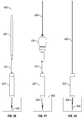
- FIG. 1is a diagrammatic representation of one embodiment of a pedicle access tool
- FIG. 2is a diagrammatic representation of one embodiment of a cannula
- FIG. 3is a diagrammatic representation of an embodiment of a cannula tip
- FIG. 4is a diagrammatic representation of another view of a cannula
- FIG. 5is a diagrammatic representation of a tool handle
- FIG. 6is a diagrammatic representation of a stylet
- FIG. 7is a diagrammatic representation of a portion of an embodiment of a pedicle access tool
- FIG. 8Ais a diagrammatic representation of a portion of an embodiment of a pedicle access tool with a trocar tip
- FIG. 8Bis a diagrammatic representation of a portion of an embodiment of a pedicle access tool with another embodiment of a tip;
- FIGS. 9A and 9Bare diagrammatic representations of another embodiment of a pedicle access tool
- FIG. 10is a diagrammatic representation of one embodiment of a rasp
- FIG. 11is a diagrammatic representation of another view of an embodiment of a rasp
- FIG. 12is a diagrammatic representation of another embodiment of a rasp
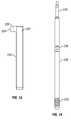
- FIG. 13is a diagrammatic representation of an embodiment of a dilator
- FIG. 14is a diagrammatic representation of an embodiment of a tap
- FIGS. 15A-15Care diagrammatic representations of one embodiment of introducing a pedicle access tool to a vertebra
- FIG. 16is a diagrammatic representation of an embodiment of a pedicle access tool with the stylet removed
- FIG. 17is a diagrammatic representation of an embodiment of a cannula in a vertebra
- FIG. 18is a diagrammatic representation of an embodiment of performing aspiration
- FIGS. 19A-19Bare diagrammatic representations of performing dilation
- FIG. 20is a diagrammatic representation of an embodiment of using a rasp
- FIG. 21is a diagrammatic representation of an embodiment of using an offset rasp
- FIG. 22is a diagrammatic representation of another embodiment of using an offset rasp
- FIG. 23is a diagrammatic representation of another embodiment of using an offset rasp
- FIG. 24is a diagrammatic representation of an embodiment of implanting bone fusion promoting material
- FIG. 25is a diagrammatic representation of an embodiment of using a tamp
- FIG. 26is a diagrammatic representation of an embodiment of installing a k-wire
- FIG. 27is a diagrammatic representation of an embodiment of removing a cannula
- FIG. 28is a diagrammatic representation of an embodiment of a k-wire installed in bone
- FIG. 29is a diagrammatic representation of an embodiment of using a rasp
- FIG. 30is a diagrammatic representation of an embodiment of using an offset rasp
- FIG. 31is a diagrammatic representation of another embodiment of using an offset rasp
- FIG. 32is a diagrammatic representation of another embodiment of using an offset rasp
- FIG. 33is a diagrammatic representation of an embodiment of implanting bone fusion promoting material
- FIG. 34is a diagrammatic representation of an embodiment of using a tamp.
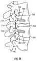
- FIG. 35is a diagrammatic representation of an embodiment of a spinal stabilization system.
- the terms “comprises,” “comprising,” “includes,” “including,” “has,” “having” or any other variation thereof,are intended to cover a non-exclusive inclusion.
- a process, product, article, or apparatus that comprises a list of elementsis not necessarily limited to only those elements but may include other elements not expressly listed or inherent to such process, process, article, or apparatus.
- “or”refers to an inclusive or and not to an exclusive or. For example, a condition A or B is satisfied by any one of the following: A is true (or present) and B is false (or not present), A is false (or not present) and B is true (or present), and both A and B are true (or present).
- any examples or illustrations given hereinare not to be regarded in any way as restrictions on, limits to, or express definitions of, any term or terms with which they are utilized. Instead these examples or illustrations are to be regarded as being described with respect to one particular embodiment and as illustrative only. Those of ordinary skill in the art will appreciate that any term or terms with which these examples or illustrations are utilized encompass other embodiments as well as implementations and adaptations thereof which may or may not be given therewith or elsewhere in the specification and all such embodiments are intended to be included within the scope of that term or terms. Language designating such non-limiting examples and illustrations includes, but is not limited to: “for example,” “for instance,” “e.g.,” “in one embodiment,” and the like.
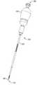
- FIG. 1is a diagrammatic representation of a pedicle access tool (PAT) 100 that can be used to prepare a vertebra for a bone screw and to facilitate posterolateral fusion.
- PATpedicle access tool
- PAT 100comprises a cannula 102 , a cannula handle 104 detachably coupled to cannula 102 and a stylet 106 that projects from cannula 102 and is removably coupled to handle 104 .
- Cannula 102 and handle 104form a continuous passage from proximate end 108 to distal end 110 .
- the continuous passageis long enough to extend from a surgical site to the exterior of a patient's body.
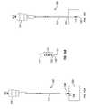
- FIG. 2is a diagrammatic representation of one embodiment of cannula 102 and FIG. 3 is a diagrammatic representation of an end portion of cannula 102 .
- Cannula 102can define a passage 111 running from a proximate end 112 to a distal end 114 .
- Cannulacan include one or more features, such as indent 116 , area 118 or other features to promote quick connection with handle 104 . While a particular quick-connect embodiment is shown for an industry standard AO quick connect, embodiments of cannula 102 can include features compatible with any desired quick connect fitting. In other embodiments cannula 102 can include threads or fittings to detachably couple to handle 104 .
- the tip 120 of cannula 102can have a shape that is selected so that the tip 120 can perforate cortical bone such that cannula 102 acts as a bone awl.
- tip 120can be a conical or other shape that transitions from a smaller to a larger diameter.
- Cannula 102can also include a threaded tap section 122 that is selected to tap a hole made by stylet 106 and tip 120 . Tip 120 can transition directly into tap section 122 or there may be some distance between tip 120 and tap section 122 . According to one embodiment, cannula 102 can be selected to have a thread major diameter that is the same as or less than the major diameter of the bone screw to be installed.
- tap section 122can have a major diameter of 4.0 mm for a screw with a major thread diameter of 4.5 mm. In other embodiments, tap section 122 can have a major diameter of 4.0 mm-4.5 mm for a screw with a major diameter of 4.5 mm. In yet another embodiment, tap section 122 can have a smaller major diameter. In some cases, if tap section 122 has too small of a major diameter, subsequent taps may be used. Tap section 122 can have any desired length along cannula 102 .
- cannula 102can have a generally cylindrical shape with a first section 124 and a second section 126 .
- First section 124can have a larger or smaller diameter than second section 126 .
- tap section 122has a major diameter that is less than or equal to the diameter of first section 124 .
- Second section 126can have a length selected so that pedicle access tool 100 only taps into a vertebra until shoulder 125 contacts the vertebra and limits further insertion.
- FIG. 4is a diagrammatic representation of another view of cannula 102 illustrating that tap section 122 can include a slot 128 .
- Slot 128can be sized to allow bone material to move into passage 111 when cannula 102 is used to tap bone.
- Cannula 102can include other features to aid in surgery including, for example, depth markings 130 , size markings or other indicia that can aid in surgery.
- FIG. 5is a diagrammatic representation of tool handle 104 .
- Tool handle 104can have an ergonomic shape, such as a rounded shape, a “T” shape or other ergonomic shape.
- Tool handle 104can include a quick connect 132 to allow for easy detachable connection to cannula 102 . While cannula 102 and handle 104 are shown as using an AO quick connect in FIGS. 2 and 5 , quick connect 132 can include industry standard quick connect or proprietary quick connect fitting. In other embodiments, tool handle 104 can detachably couple to cannula 102 in other manners such as, but not limited to, using threads, pins or suitable quick connect or non-quick connect connections.
- Tool handle 104can connect to cannula 102 so that passage 134 forms a continuous passage with passage 111 of cannula 102 .
- Handle 104 and cannula 102can, in one embodiment, form a seal so that fluids can flow from cannula 102 through handle 104 without leaking at the connection.
- Handle 104can be a ratcheting handle to facilitate tapping.
- Handle 104can also detachably couple to stylet 106 .
- handle 104can include a Luer lock connection, a reverse thread Luer lock connection 136 , quick connect connection or other connection to detachably couple to stylet 106 .
- the connection between handle 104 and stylet 106can allow stylet 106 to be positioned in various positions so that the tip of stylet 106 extends a desired distance from the tip of cannula 102 .
- FIG. 6is a diagrammatic representation of one embodiment of stylet 106 including a stylet handle 138 and stylet needle 140 .
- Needle 140is long enough so that tip 142 extends beyond tip 120 of cannula 102 (shown in FIG. 7 ). Tip 142 of needle 140 can be sharp enough to sink into pedicle bone.
- Handle 138can include threads 144 or other connection to detachably couple to handle 104 .
- Handle 138can have a shape that is selected so that it is relatively easy for a surgeon to uncouple stylet 106 from handle 104 and withdraw stylet 106 from PAT 100 .
- FIG. 7is a diagrammatic representation of one embodiment of a portion of PAT 100 proximate to distal end 110 including tip 142 of needle 140 , tip 120 of cannula 102 and tap section 122 of cannula 102 .
- the tip 142can extend a select distance beyond tip 120 so that there is a desired distance “d 1 ” to the start of tap section 120 .
- d 1can be 20 mm.
- d 1range from 5 mm to 30 mm. Other distances can be used as needed or desired for a particular procedure.
- the connection between handle 104 and stylet 106can, in an embodiment, allow the surgeon to select how far tip 142 extends beyond cannula 102 to achieve a desired d 1 .
- Tip 142can have various configurations.
- FIG. 8Ais a diagrammatic representation showing a trocar tip while FIG. 8B is a diagrammatic representation showing another embodiment of a tip.
- tip 142can have any suitable shape for piercing vertebral bone, including, but not limited to, beveled and trocar tips.
- FIG. 9Aillustrates another embodiment of a PAT 150 having a cannula 152 , handle 154 and stylet 156 extending from cannula 152 .
- handle 154is a “T” shaped handle and cannula 152 has a constant diameter along most of its length.
- FIG. 9Billustrates a portion of PAT 150 showing tip 160 , tap section 162 and stylet tip 166 .
- Stylet tip 156can be sufficiently sharp to pierce vertebral bone.
- Tip 160 of cannula 152can have tapered, conical or other shape that allows cannula 152 to act as an awl to puncture through the cortical bone of the vertebra.
- Tap section 162can include a set of mini-threads that allow cannula 152 to be screwed into the hole formed by tip 160 .
- the threadsin one embodiment, can have a smaller diameter and smaller pitch than the threads of the bone screw to be inserted. According to one embodiment, the same cannula 152 can be used regardless of the size screw being inserted and subsequent taps can be used to increase the diameter of the hole.
- Embodiments of pedicle access toolscan include a cannula and needles formed of biocompatible materials including titanium, PEEK, stainless steel or other material.
- cannula 102may have some flexibility, it can be rigid enough so that, unlike a k-wire, it does not easily bend when manipulated or bumped by a surgeon. Portions of the tool not inserted into the body can be made of metal, plastic or other suitable material.
- the pedicle access toolcan be formed of a sterilized material and be disposable or constructed to be autoclaved.
- cannula 102 and needle 140can be formed of a material that can be discerned during medical imaging such as fluoroscopy, while the handles are made of a radio-lucent material.
- Embodiments of a pedicle access toolcan act as an awl, tap and cannula reducing the number of tools required for a surgery. Furthermore, because the cannula can thread into the vertebra, the cannula can be secured to the bone during surgery. Consequently, the cannula, rather than a k-wire, can be used to guide some tools to a surgical site. Tools such as rasps, tamps, dilators, taps and others can be adapted to use cannula 102 as a guide.
- FIG. 10is a diagrammatic representation of one embodiment of a bone rasp 200 that includes a rasp end 202 having teeth or other features adapted to roughen, bloody or otherwise prepare the surface of a vertebra for bone graft material.
- Rasp 200can also include a portion 204 adapted for quick connection or other connection to a handle.
- Rasp 200can include depth markings 206 or other features to aid in surgery.
- FIG. 11is a cross-sectional view of one embodiment of bone rasp 200 showing passage 208 .
- Passage 208is open at rasp end 202 and can have a diameter so that bone rasp 200 can fit over cannula 102 .
- passage 208can be as small as possible to preserve the working surface area of rasp end 202 while still allowing rasp 200 to fit over cannula 102 .
- Passage 208can run through the entire length of rasp 200 or can terminate in rasp 200 .
- Passage 208can be centered or offset from the center of bone rasp 200 .
- a portion of passage 208can be open to a slot on the side of rasp 200 so that rasp 200 can be angled relative to cannula 102 as discussed below in conjunction with FIG. 23 .
- the outer of diameter of rasp 200can be selected so that rasp 200 is small enough to fit inside a selected size dilator.
- FIG. 12is a diagrammatic representation of one embodiment of an offset rasp 210 that include a rasp body 212 and a rasp end 214 .
- Rasp end 214can have teeth or other features adapted to roughen, bloody or otherwise prepare bone for a bone graft.
- rasp 210can be sized to fit into a dilator next to cannula 102 or a k-wire.
- FIG. 13is a diagrammatic representation of a dilator 220 that defines a passage 222 having a size to accommodate a selected rasp or other tool.
- Dilator 220can include an extension 224 having a passage 226 sized to fit over cannula 102 or a k-wire.
- FIG. 14is a diagrammatic representation of a tap 230 that can include a threaded section 232 to tap a hole in preparation for a bone screw.
- a particular sized tap 230can be chosen based on the size of bone screw to be inserted.
- a passagecan accommodate cannula 102 or a k-wire so that tap 230 can fit over cannula 102 .
- Tap 230can include a portion 234 adapted for connection with a handle or can include a non-detachable handle. Tap 230 can include depth markings or other features to aid in surgery.
- PAT 100can be used to aid in preparing a surgical site for installation of bone screws and to aid in posterolateral fusion.
- minimally invasive proceduresa small opening may need to be made in a patient.
- the surgical proceduremay be performed through a 2 cm to 4 cm incision formed in the skin of the patient.
- the incisionmay be above and substantially between the vertebrae to be stabilized.
- the incisionmay be above and substantially halfway between the vertebrae to be stabilized.
- the PAT, dilators, and/or a tissue wedgemay be used to provide access to the vertebrae to be stabilized without the need to form an incision with a scalpel through muscle and other tissue between the vertebrae to be stabilized.
- a minimally invasive proceduremay reduce an amount of post-operative pain felt by a patient as compared to invasive spinal stabilization procedures and reduce recovery time for the patient as compared to invasive spinal procedures.
- Embodiments of posterolateral fusion described hereincan be performed as a minimally invasive procedure.
- FIGS. 15A , 15 B and 15 Care diagrammatic representations of introducing PAT 100 into the bone.
- a surgeonselects the surgical site and guides PAT 100 to the surgical site using medical imaging until tip 142 contacts bone.
- the surgical siteis the pedicle (represented at 302 ) of a vertebra.
- FIG. 15Billustrates tip 142 inserted into the bone.
- the surgeoncan force tip 120 through the bone by gently tapping on handle 104 with a mallet or otherwise driving tip 120 into the cortical bone.
- PAT 100can be turned using handle 104 to cause tap section 122 to tap a hole 304 a selected depth as shown in FIG. 15C . Shoulder 125 can prevent PAT 100 from penetrating too deeply into pedicle 302 .
- PAT 100can act as a targeting needle, awl and tap in a single tool.
- FIG. 16is a diagrammatic representation of tool 100 in pedicle 302 with stylet 106 removed.
- a syringecan be connected to connection 134 and tissue aspirated through cannula 102 and handle 104 .
- an aspiration stepcan occur later or not occur at all.
- handle 104can be removed.
- FIG. 18is a diagrammatic representation of an embodiment of performing aspiration through cannula 102 .
- a syringe 308can be connected to cannula 102 using a quick connect adapter 310 or other mechanism to connect to cannula 102 .
- Syringe 308can be used to aspirate a desired amount of bone marrow or other material through cannula 102 .
- Tissue around cannula 102can be dilated using one or more dilators that fit over cannula 102 to dilate tissue a desired amount.
- FIGS. 19A and Bare diagrammatic representations of sequentially dilating tissue about cannula 102 using dilator 320 and then larger dilator 322 .
- the depth markings 130 on cannula 102can show the depth of tip 120 past dilator 322 .
- rasp 200can be guided down cannula 102 to the vertebra.
- FIG. 20is a diagrammatic representation of rasp 200 in place over cannula 102 and inside dilator 322 .
- a handle 324can be used to manipulate rasp 200 .
- handle 324can be the same handle as handle 104 or can be a modular handle used with other tools such as drivers.
- Depth markings on rasp 200indicate the depth of rasp end 202 relative to the end of dilator 322 .
- Rasp 200can be used to de-corticate or otherwise prepare the pedicle surface for a bone graft.
- rasp 200is an in-line rasp that is coaxial with cannula 102 and that prepare the bone around cannula 102 up to the diameter of rasp 200 . Areas further offset from cannula 102 can be prepared including, for example, inferior and superior facet surfaces.
- FIG. 21is a diagrammatic representation of a rasp 210 that fits next to cannula 102 in dilator 322 . Rasp 210 and dilator 322 can be moved in a circle around cannula 102 to prepare a larger area.
- FIG. 22is a diagrammatic representation of a rasp 210 used in conjunction with a dilator 220 . Dilator 220 can be rotated about cannula 102 using extension 224 . In one embodiment multiple dilators can be used having different lengths of extension 224 so that rasp 330 can prepare areas closer to and further away from cannula 102 .
- FIG. 23is a diagrammatic representation of another embodiment of preparing bone.
- a single rasp 340can be used to prepare the bone both immediately around and further away from cannula 102 .
- Rasp 340 and dilator 342can include slots in their walls so that they can tilt relative to cannula 102 .
- Rasp 340can be oriented coaxial with cannula 102 to prepare an area close to cannula 102 and tilted at various angles to prepare a larger area.
- Bone graft or other fusion promoting materialscan be placed across de-corticated or otherwise prepared surfaces for posterolateral fusion.
- bone fusion promoting materialsinclude, but are not limited to, iliac crest autographs, bone grafts from other sources, bone morphogenetic proteins or other bone fusion materials.
- FIG. 24is a diagrammatic representation of one embodiment of introducing bone fusion material.
- a disc of fusion promoting material 350that has a hole large enough to fit over cannula 102 is lead to the surgical site down cannula 102 .
- the holecan be large enough so that the shaft of a bone screw can pass through the hole, but the collar or head of the bone screw will press disc 350 into the vertebra when the bone screw is secured.
- the fusion materialcan be introduced as particles 352 that can be poured down dilator 320 .
- both a disc (or other shaped piece) of bone fusion promoting material and particlescan be used together.
- a disc 350can be used at the center of an area and particles used in a broader area.
- FIG. 25illustrates and embodiment of a tamp 360 pressing on bone fusion material 350 .
- tamp 360can include a tamp body 362 that is small enough to fit in dilator 322 and a generally flat tamping end 364 .
- Tamp 360can further include a passage at the center of tamp 360 or offset from the center of tamp 360 that can accommodate cannula 102 .
- inline and offset tampscan be similar to previously discussed embodiments of rasps, but with flat or otherwise shaped tamping ends to press the bone fusion material into the prepared bone.
- FIG. 26is a diagrammatic representation of installing a k-wire 400 .
- K-wire 400can be formed of stainless steel, nitinol or other material.
- K-wire 400is advanced through cannula 102 until the tip 404 of k-wire 400 is advanced beyond tip 120 of cannula 102 into the vertebra.
- a dilator or other support 402can be used to hold the k-wire straight. If needed, a mallet or other tool can be used to drive the k-wire. Installation of the k-wire can be monitored under Fluoroscopy or other medical imaging.
- FIG. 27is a diagrammatic representation of one embodiment of removing cannula 102 .
- handle 104can be lead down k-wire 400 and reattached to cannula 102 .
- Cannula 102can then be unthreaded from the vertebral body leaving k-wire 400 inserted in the bone through the end of hole 304 as shown, for example, in FIG. 28 .
- K-wire 400can be used to guide bone screws or other tools to the surgical site.
- a spinal stabilization systemcan be installed in the body using k-wire 400 .
- the spinal stabilization systemcan include bone anchor assemblies that secure a rigid or dynamic stabilization rod.
- the bone anchor assembliescan be lead to the surgical site using k-wire 400 according to methods known or developed in the art. If a disc 350 of bone fusion promoting material is inserted as described above, the shaft of a bone anchor assemblies can pass through the hole in disc 350 while the collar presses bone fusion promoting material into the respective vertebrae. Over time, discs 350 or other bone fusion material will promote bone growth between the vertebrae to cause vertebrae to fuse together adding stability to the spine.
- cannula 102as a guide provides the advantage of using a k-wire for fewer steps. Because tip 120 is relatively blunt compared to the tip of a k-wire, it is less likely that cannula 120 will push through a vertebra if inadvertently pushed during surgery. Furthermore, cannula 102 can be easier to manage because it is more rigid than a k-wire and can remain in one place during surgery.
- k-wire 400as a guide rather than cannula 102 .
- Various toolscan be sized to fit over the k-wire. These may be the same tools that can fit over cannula 102 or can be tools with smaller diameter passages that can be guided down the k-wire 400 .
- the k-wire 400can be installed using PAT 100 or other targeting needle. If PAT 100 is not used, separate awls and taps can guided down k-wire 400 to form hole 304 .
- FIG. 29is a diagrammatic representation of rasp 600 in place over k-wire and inside dilator 322 .
- a handlecan be used to manipulate rasp 600 .
- the handlecan be the same handle as handle 104 or can be a modular handle used with other tools such as drivers.
- Rasp 600can be selected so that the depth markings on rasp 600 indicate the depth of rasp end 602 relative to the end of dilator 322 .
- Rasp 600can be used to de-corticate or otherwise prepare the pedicle surface for a bone graft.
- Rasp 600can be similar to rasp 200 , but can have a smaller passage to accommodate k-wire 400 .
- a rasp with a larger diameter passage, such as rasp 200can be used over k-wire 400 .
- rasp 600is an in-line rasp that is coaxial with k-wire 400 and prepares the bone around cannula k-wire 400 up to the diameter of rasp 600 . Areas further offset from k-wire 400 can be prepared including, for example, inferior and superior facet surfaces.
- FIG. 30is a diagrammatic representation of using a rasp 635 that fits in dilator 322 next to k-wire 400 . Dilator 322 can be rotate about k-wire 400 so that rasp 635 can prepare a larger area.
- FIG. 31is a diagrammatic representation of a rasp 638 used in conjunction with a dilator 220 . Dilator 220 can be rotated about k-wire 400 using extension 224 .
- multiple dilatorscan be used having different lengths of extension 224 so that rasp 330 can prepare areas closer to and further away from cannula k-wire 400 . While, in this example, extension 224 can be sized to fit over either cannula 102 or k-wire 400 , in other embodiments, extension 224 can be sized to fit over k-wire 400 but not cannula 102 .
- FIG. 32is a diagrammatic representation of another embodiment of preparing bone.
- a single rasp 640can be used to prepare the bone both immediately around and further away from k-wire 400 .
- Rasp 640 and dilator 642can include slots in their walls so that they can tilt relative to cannula k-wire 400 .
- Rasp 640can be oriented be coaxial with k-wire 400 or tilted at various angles relative to k-wire 400 to prepare a larger area.
- FIG. 33is a diagrammatic representation of one embodiment of introducing bone fusion material.
- a disc of fusion promoting material 650has a hole that is large enough to fit over k-wire 400 so that it can be lead to the surgical over k-wire 400 .
- the holecan be large enough so that the shaft of a bone screw can pass through the hole, but the collar or head of the bone screw will press disc 650 into the vertebra when the bone screw is secured.
- FIG. 33also illustrates that bone fusion material can be introduced as particles 652 that can be poured down dilator 322 rather than or in addition to using disc 650 .
- FIG. 34illustrates an embodiment of a tamp 660 pressing on bone fusion material 650 .
- tamp 660can include a tamp body 662 that is small enough to fit in dilator 322 and a generally flat tamping end 664 .
- Tamp 660can further include a passage at the center of tamp 660 or offset from the center of tamp 660 that can accommodate k-wire 400 . While a particular embodiment of an in-line tamp is shown, various embodiments of in-line and offset tamps can be similar to previously discussed embodiments of rasps but with flat or otherwise shaped tamping ends to press the bone fusion material.
- k-wire 400can also be used as guide in various steps of a posterolateral fusion procedure.
- the k-wirecan be introduced using a targeting needle or PAT 100 .
- PAT 100can be used to form and tap a hole and then be removed.
- K-wire 400can be used as a guide for the remainder of the procedure.
- cannula 102can be used during the rasping stages and the removed while k-wire 400 can be used when bone fusion material is introduced and during tamping.
- cannula 102can be used to guide bone fusion material to a site and k-wire 400 used to guide a tamp to the site.
- k-wire 400used to guide a tamp to the site.
- a raspcan be lead to a surgical site using a rasp guide
- a tampcan be lead to the surgical site using a tamp guide
- bone fusion promoting materialcan be lead to the surgical site using a bone fusion promoting material guide.
- the guide in each stepcan be a cannula, k-wire or other guide.
- the cannula of pedicle access toolcan be used as the guide for various steps. Additional tools, such as a tap or other tool, can be lead to a surgical site using a cannula of a pedicle access tool or a k-wire as needed or desired.
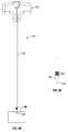
- FIG. 35illustrates an embodiment of a spinal stabilization system 700 installed on vertebra prepared to promote posterolateral fusion.
- Spinal stabilization system 700can include bone anchors 702 and 704 installed in vertebrae 706 and 708 respectively.
- Bone anchors 702 and 704can be polyaxial or monoaxial bone screws or other bone anchors known in the art.
- the bone anchorscan be cannulated so that they can pass over a k-wire.
- Each bone anchorcan include a collar (e.g., collars 710 and 712 ) that secures a rigid or dynamic spinal stabilization rod 714 .
- collars 710 and 712press a disc of bone fusion promoting material 350 into an area of the pedicle prepared by a rasp. Additional bone fusion promoting material 352 can be placed further away from bone anchors 702 and 704 to promote a broader region of fusion. Over time, bone will fuse between vertebrae 706 and 708 to stabilize the spine.
Landscapes
- Health & Medical Sciences (AREA)
- Surgery (AREA)
- Life Sciences & Earth Sciences (AREA)
- Orthopedic Medicine & Surgery (AREA)
- Molecular Biology (AREA)
- Animal Behavior & Ethology (AREA)
- Engineering & Computer Science (AREA)
- Biomedical Technology (AREA)
- Heart & Thoracic Surgery (AREA)
- Medical Informatics (AREA)
- Veterinary Medicine (AREA)
- Nuclear Medicine, Radiotherapy & Molecular Imaging (AREA)
- General Health & Medical Sciences (AREA)
- Public Health (AREA)
- Dentistry (AREA)
- Oral & Maxillofacial Surgery (AREA)
- Neurology (AREA)
- Pathology (AREA)
- Surgical Instruments (AREA)
- Prostheses (AREA)
Abstract
Description
Claims (15)
Priority Applications (2)
| Application Number | Priority Date | Filing Date | Title |
|---|---|---|---|
| US12/550,235US8814914B2 (en) | 2009-08-28 | 2009-08-28 | Fusion method and pedicle access tool |
| EP10008297.3AEP2289433B1 (en) | 2009-08-28 | 2010-08-09 | Pedicle access tool |
Applications Claiming Priority (1)
| Application Number | Priority Date | Filing Date | Title |
|---|---|---|---|
| US12/550,235US8814914B2 (en) | 2009-08-28 | 2009-08-28 | Fusion method and pedicle access tool |
Publications (2)
| Publication Number | Publication Date |
|---|---|
| US20110054537A1 US20110054537A1 (en) | 2011-03-03 |
| US8814914B2true US8814914B2 (en) | 2014-08-26 |
Family
ID=43304779
Family Applications (1)
| Application Number | Title | Priority Date | Filing Date |
|---|---|---|---|
| US12/550,235Active2031-07-29US8814914B2 (en) | 2009-08-28 | 2009-08-28 | Fusion method and pedicle access tool |
Country Status (2)
| Country | Link |
|---|---|
| US (1) | US8814914B2 (en) |
| EP (1) | EP2289433B1 (en) |
Cited By (13)
| Publication number | Priority date | Publication date | Assignee | Title |
|---|---|---|---|---|
| CN105476707A (en)* | 2015-10-30 | 2016-04-13 | 自贡市第四人民医院 | Individual occipitocervical fusion screw feeding navigation template manufacturing method |
| US20170027592A1 (en)* | 2015-07-31 | 2017-02-02 | Warsaw Orthopedic, Inc. | Surgical instrument and method |
| US9675363B2 (en) | 2015-11-13 | 2017-06-13 | Advance Research System, Llc | Surgical tools having application for spinal surgical procedures and method of use |
| US20180049754A1 (en)* | 2015-03-13 | 2018-02-22 | Redemed S.R.L. | Intervertebral prosthesis, apparatus for implanting intervertebral prostheses and surgical method for implanting intervertebral prostheses, particularly for percutaneous mini-invasive surgery procedures |
| US20180256201A1 (en)* | 2014-02-21 | 2018-09-13 | Surgentec, Llc | Handles for needle assemblies |
| US10123829B1 (en) | 2015-06-15 | 2018-11-13 | Nuvasive, Inc. | Reduction instruments and methods |
| US10617530B2 (en) | 2011-07-14 | 2020-04-14 | Seaspine, Inc. | Laterally deflectable implant |
| US10973558B2 (en) | 2017-06-12 | 2021-04-13 | K2M, Inc. | Screw insertion instrument and methods of use |
| US11033341B2 (en) | 2017-05-10 | 2021-06-15 | Mako Surgical Corp. | Robotic spine surgery system and methods |
| US11065069B2 (en) | 2017-05-10 | 2021-07-20 | Mako Surgical Corp. | Robotic spine surgery system and methods |
| WO2022140564A1 (en)* | 2020-12-23 | 2022-06-30 | Formae, Inc. | Instruments and methods for preparing patient recipient site and installing medical implant |
| US20250082381A1 (en)* | 2023-09-12 | 2025-03-13 | Conventus Orthopaedics, Inc. | Cannulated implant removal tools and method |
| US12262927B2 (en) | 2020-12-10 | 2025-04-01 | K2M, Inc. | Screw insertion instrument and methods of use |
Families Citing this family (51)
| Publication number | Priority date | Publication date | Assignee | Title |
|---|---|---|---|---|
| WO2007121271A2 (en) | 2006-04-11 | 2007-10-25 | Synthes (U.S.A) | Minimally invasive fixation system |
| WO2010031064A1 (en) | 2008-09-15 | 2010-03-18 | Clearview Patient Safety Technologies, Llc | Lumbar puncture detection device |
| CN102497828B (en) | 2009-05-20 | 2015-09-09 | 斯恩蒂斯有限公司 | What patient installed retracts part |
| US8814914B2 (en)* | 2009-08-28 | 2014-08-26 | Zimmer Spine, Inc. | Fusion method and pedicle access tool |
| US9204906B2 (en) | 2009-10-22 | 2015-12-08 | Nuvasive, Inc. | Posterior cervical fusion system and techniques |
| US10098674B2 (en) | 2009-10-22 | 2018-10-16 | Nuvasive, Inc. | System and method for posterior cervical fusion |
| US8545505B2 (en)* | 2010-01-15 | 2013-10-01 | Pioneer Surgical Technology, Inc. | Low friction rod persuader |
| US8535318B2 (en) | 2010-04-23 | 2013-09-17 | DePuy Synthes Products, LLC | Minimally invasive instrument set, devices and related methods |
| US8641717B2 (en) | 2010-07-01 | 2014-02-04 | DePuy Synthes Products, LLC | Guidewire insertion methods and devices |
| CN103717159B (en) | 2011-05-27 | 2016-08-17 | 新特斯有限责任公司 | Minimally Invasive Spinal Fixation System Including Vertebral Alignment Features |
| US20130150752A1 (en)* | 2011-12-12 | 2013-06-13 | Karl W. Swann | Apparatus for Bone Aspiration |
| US9463052B2 (en) | 2012-01-12 | 2016-10-11 | Integrity Implants Inc. | Access assembly for anterior and lateral spinal procedures |
| US20130289572A1 (en)* | 2012-04-25 | 2013-10-31 | Kyphon Sarl | Positional guide |
| EP2849656B1 (en) | 2012-05-14 | 2017-10-04 | Synthes GmbH | Bone access instrument |
| US20140088647A1 (en)* | 2012-09-21 | 2014-03-27 | Atlas Spine, Inc. | Minimally invasive spine surgery instruments: spinal rod with flange |
| US9414868B1 (en)* | 2012-12-13 | 2016-08-16 | Spinelogik, Inc. | Guide placement device and method of use |
| CN103054623B (en)* | 2013-01-15 | 2015-03-11 | 温州医学院附属第一医院 | Foramen reaming tool used during transforaminal approach surgery under spinal endoscope |
| US9237894B2 (en) | 2013-01-31 | 2016-01-19 | Depuy Mitek, Llc | Methods and devices for forming holes in bone to stimulate bone growth |
| US10342498B2 (en)* | 2013-02-21 | 2019-07-09 | Medtronic Holding Company Sàrl | Cannula with image markers to indicate expandable device size |
| US9433445B2 (en)* | 2013-03-14 | 2016-09-06 | DePuy Synthes Products, Inc. | Bone anchors and surgical instruments with integrated guide tips |
| US10820913B2 (en)* | 2013-03-15 | 2020-11-03 | Teleflex Life Sciences Limited | Intraosseous device handles, systems, and methods |
| US10149770B2 (en) | 2013-07-09 | 2018-12-11 | Seaspine, Inc. | Orthopedic implant with adjustable angle between tissue contact surfaces |
| US20150100077A1 (en)* | 2013-10-09 | 2015-04-09 | Safewire, LLC | Thread forming jamshidi assembly |
| US9820865B2 (en) | 2013-10-31 | 2017-11-21 | Nlt Spine Ltd. | Adjustable implant |
| CN104287815B (en)* | 2014-06-16 | 2017-01-11 | 南通舟可信息科技有限公司 | 3D printing percutaneous vertebral pedicle guide plate, preparation method of 3D printing percutaneous vertebral pedicle guide plate, and using method of 3D printing percutaneous vertebral pedicle guide plate |
| US10492923B2 (en) | 2014-06-25 | 2019-12-03 | Seaspine, Inc. | Expanding implant with hinged arms |
| US9855087B2 (en) | 2014-08-04 | 2018-01-02 | DePuy Synthes Products, LLC | Methods and devices for spinal screw insertion |
| US10058350B2 (en) | 2015-09-24 | 2018-08-28 | Integrity Implants, Inc. | Access assembly for anterior and lateral spinal procedures |
| CN105596077A (en)* | 2016-02-06 | 2016-05-25 | 贺新宁 | Universal screw-setting device for pedicle screw |
| CN106137335A (en)* | 2016-07-15 | 2016-11-23 | 于海龙 | A kind of Thoracolumbar disk percutaneous puncture device and using method thereof |
| JP6960133B2 (en)* | 2016-08-19 | 2021-11-05 | 国立大学法人東北大学 | Screw reinforcement insertion device |
| IL247684A0 (en)* | 2016-09-07 | 2017-01-31 | Waismed Ltd | Cannula for use in intraosseous injections |
| US10433883B2 (en) | 2017-06-27 | 2019-10-08 | Medos International Sarl | Spinal screw insertion devices and methods |
| US10779872B2 (en) | 2017-11-02 | 2020-09-22 | Medos International Sarl | Bone anchor insertion instruments and methods |
| US11666367B2 (en)* | 2018-05-30 | 2023-06-06 | Tushar Goradia | Guidance apparatus for implantation into bone and related methods of use |
| US11648000B2 (en)* | 2018-07-30 | 2023-05-16 | Braunvest Llc | Vertebral probes and related surgical methods |
| US12232781B2 (en)* | 2018-07-30 | 2025-02-25 | BraunVest, LLC | Cortical/cancellous bone probes and related surgical methods |
| USD948045S1 (en) | 2018-12-13 | 2022-04-05 | Spinal Generations, Llc | Bone instrument shank |
| US11602357B2 (en)* | 2018-12-13 | 2023-03-14 | Spinal Generations, Llc | Drill bit with delivery device fitting and method of use thereof |
| US11344353B2 (en) | 2018-12-20 | 2022-05-31 | Integrity Implants Inc. | Surgical guidance device and system for insertion thereof |
| US11484351B2 (en) | 2018-12-20 | 2022-11-01 | Integrity Implants Inc. | Surgical device for insertion of guide wire and pedicle screw |
| US11633223B2 (en) | 2018-12-20 | 2023-04-25 | Integrity Implants Inc. | Surgical guidance device |
| US11123113B2 (en) | 2019-06-13 | 2021-09-21 | Medos International Sarl | Screw inserter instruments and methods |
| US11224472B2 (en) | 2019-06-13 | 2022-01-18 | Medos International Sarl | Screw inserter instruments and methods |
| US11612419B2 (en)* | 2020-01-24 | 2023-03-28 | Warsaw Orthopedic, Inc. | Spinal implant system and method |
| CN111358599A (en)* | 2020-03-03 | 2020-07-03 | 广东施泰宝医疗科技有限公司 | Intervertebral fusion device capable of achieving in-situ bone grafting and secondary bone grafting and matched tool thereof |
| EP3892215B1 (en)* | 2020-04-09 | 2023-10-11 | Biedermann Technologies GmbH & Co. KG | Surgical instrument |
| CN113262034B (en)* | 2021-06-04 | 2025-03-18 | 北京市富乐科技开发有限公司 | Axis vertebral fracture reduction surgical instrument |
| US20250009362A1 (en)* | 2021-11-18 | 2025-01-09 | Phasor Health, Llc | Quick-connect k-wire module |
| KR20230122791A (en)* | 2022-02-15 | 2023-08-22 | 신흥섭 | Bone fixation device for spinal fusion and surgical tool set including the same |
| CN118512233B (en)* | 2024-05-24 | 2025-03-14 | 董岩 | Adjustable acromion bone knife |
Citations (32)
| Publication number | Priority date | Publication date | Assignee | Title |
|---|---|---|---|---|
| DE2542056A1 (en) | 1975-09-20 | 1977-03-31 | Hans Dr Reimer | Tool for roughening bone channel for stem of endoprosthesis - is tapping twist drill with wide chip flutes |
| US5196015A (en)* | 1992-04-30 | 1993-03-23 | Neubardt Seth L | Procedure for spinal pedicle screw insertion |
| US5946988A (en) | 1992-02-27 | 1999-09-07 | Howmedica Gmbh | Tool for driving pedicle screws |
| EP0948939A2 (en) | 1998-04-09 | 1999-10-13 | Howmedica GmbH | Pedicle screw and mounting tool |
| US6019776A (en)* | 1997-10-14 | 2000-02-01 | Parallax Medical, Inc. | Precision depth guided instruments for use in vertebroplasty |
| US20030018337A1 (en) | 2001-07-17 | 2003-01-23 | Davis Reginald J. | Bone drill and tap combination |
| US20030050644A1 (en) | 2001-09-11 | 2003-03-13 | Boucher Ryan P. | Systems and methods for accessing and treating diseased or fractured bone employing a guide wire |
| US20040092988A1 (en) | 2002-11-08 | 2004-05-13 | Shaolian Samuel M. | Transpedicular intervertebral disk access methods and devices |
| US6770079B2 (en) | 1999-03-16 | 2004-08-03 | American Osteomedix, Inc. | Apparatus and method for fixation of osteoporotic bone |
| WO2005039423A1 (en) | 2003-10-21 | 2005-05-06 | Endius. Inc. | Piercing and tapping instrument and method for preparing a bone to receive an implant |
| US20050107800A1 (en) | 2003-11-19 | 2005-05-19 | Frankel Bruce M. | Fenestrated bone tap and method |
| US20060030872A1 (en) | 2004-08-03 | 2006-02-09 | Brad Culbert | Dilation introducer for orthopedic surgery |
| US20070016219A1 (en)* | 2005-07-14 | 2007-01-18 | Levine Marc J | Vertebral Marker Devices and Installation Methods |
| US20070270896A1 (en) | 2006-04-21 | 2007-11-22 | Mi4Spine, Llc | Pedicle access device |
| WO2008008522A2 (en) | 2006-07-13 | 2008-01-17 | Highgate Orthopedics, Inc. | Devices and methods for stabilizing a spinal region |
| US20080051793A1 (en) | 2006-08-04 | 2008-02-28 | David Erickson | Drill-tap tool |
| US20080108991A1 (en) | 2006-11-08 | 2008-05-08 | General Electric Company | Method and apparatus for performing pedicle screw fusion surgery |
| US20080114403A1 (en) | 2006-11-09 | 2008-05-15 | Zimmer Spine, Inc. | Minimally invasive pedicle screw access system and associated method |
| US20080300605A1 (en) | 2007-06-01 | 2008-12-04 | Rinner James A | Pedicle protractor tool |
| US20090138043A1 (en)* | 2007-11-28 | 2009-05-28 | Medtronic Spine Llc | Threaded access cannula and methods of using the same |
| US20090138044A1 (en) | 2007-11-28 | 2009-05-28 | Bergeron Brian J | Stabilization system and method |
| US20100030065A1 (en)* | 2006-11-03 | 2010-02-04 | Farr Morteza M | Surgical access with target visualization |
| US20100331891A1 (en)* | 2009-06-24 | 2010-12-30 | Interventional Spine, Inc. | System and method for spinal fixation |
| US20110054537A1 (en)* | 2009-08-28 | 2011-03-03 | Zimmer Spine Austin, Inc. | Fusion method and pedicle access tool |
| US20110098628A1 (en)* | 2007-07-25 | 2011-04-28 | Yeung Jeffrey E | Internal and external disc shunts alleviate back pain |
| US20110144688A1 (en)* | 1994-01-26 | 2011-06-16 | Kyphon SÀRL | Devices and methods using an expandable body with internal restraint for compressing cancellous bone |
| US20110237861A1 (en)* | 2006-10-20 | 2011-09-29 | Ellipse Technologies, Inc. | Adjustable implant and method of use |
| US20120071929A1 (en)* | 2004-02-17 | 2012-03-22 | Alan Chervitz | Linked Bilateral Spinal Facet Implants and Methods of Use |
| US20120130380A1 (en)* | 2010-02-10 | 2012-05-24 | Bacoustics, Llc | Surgical Saw Blade |
| US20120221006A1 (en)* | 2006-10-16 | 2012-08-30 | Depuy Spine, Inc. | Method for Manipulating Intervertebral Tissue |
| US20130197563A1 (en)* | 2002-09-30 | 2013-08-01 | Advanced Polymers, Inc. | Apparatus and methods for treating bone structures, tissues and ducts using a narrow gauge cannula system |
| US20130297025A1 (en)* | 2001-11-19 | 2013-11-07 | Grampian Health Board | Intervertebral disc prosthesis |
- 2009
- 2009-08-28USUS12/550,235patent/US8814914B2/enactiveActive
- 2010
- 2010-08-09EPEP10008297.3Apatent/EP2289433B1/ennot_activeNot-in-force
Patent Citations (36)
| Publication number | Priority date | Publication date | Assignee | Title |
|---|---|---|---|---|
| DE2542056A1 (en) | 1975-09-20 | 1977-03-31 | Hans Dr Reimer | Tool for roughening bone channel for stem of endoprosthesis - is tapping twist drill with wide chip flutes |
| US5946988A (en) | 1992-02-27 | 1999-09-07 | Howmedica Gmbh | Tool for driving pedicle screws |
| US5196015A (en)* | 1992-04-30 | 1993-03-23 | Neubardt Seth L | Procedure for spinal pedicle screw insertion |
| US20110144688A1 (en)* | 1994-01-26 | 2011-06-16 | Kyphon SÀRL | Devices and methods using an expandable body with internal restraint for compressing cancellous bone |
| US6019776A (en)* | 1997-10-14 | 2000-02-01 | Parallax Medical, Inc. | Precision depth guided instruments for use in vertebroplasty |
| EP0948939A2 (en) | 1998-04-09 | 1999-10-13 | Howmedica GmbH | Pedicle screw and mounting tool |
| US6770079B2 (en) | 1999-03-16 | 2004-08-03 | American Osteomedix, Inc. | Apparatus and method for fixation of osteoporotic bone |
| US20030018337A1 (en) | 2001-07-17 | 2003-01-23 | Davis Reginald J. | Bone drill and tap combination |
| US20030050644A1 (en) | 2001-09-11 | 2003-03-13 | Boucher Ryan P. | Systems and methods for accessing and treating diseased or fractured bone employing a guide wire |
| US20130297025A1 (en)* | 2001-11-19 | 2013-11-07 | Grampian Health Board | Intervertebral disc prosthesis |
| US20130197563A1 (en)* | 2002-09-30 | 2013-08-01 | Advanced Polymers, Inc. | Apparatus and methods for treating bone structures, tissues and ducts using a narrow gauge cannula system |
| US7241297B2 (en) | 2002-11-08 | 2007-07-10 | Sdgi Holdings, Inc. | Transpedicular intervertebral disk access methods and devices |
| US20040092988A1 (en) | 2002-11-08 | 2004-05-13 | Shaolian Samuel M. | Transpedicular intervertebral disk access methods and devices |
| US7318826B2 (en) | 2002-11-08 | 2008-01-15 | Sdgi Holdings, Inc. | Transpedicular intervertebral disk access methods and devices |
| WO2005039423A1 (en) | 2003-10-21 | 2005-05-06 | Endius. Inc. | Piercing and tapping instrument and method for preparing a bone to receive an implant |
| US20050107800A1 (en) | 2003-11-19 | 2005-05-19 | Frankel Bruce M. | Fenestrated bone tap and method |
| US20120071929A1 (en)* | 2004-02-17 | 2012-03-22 | Alan Chervitz | Linked Bilateral Spinal Facet Implants and Methods of Use |
| US20060030872A1 (en) | 2004-08-03 | 2006-02-09 | Brad Culbert | Dilation introducer for orthopedic surgery |
| US20080287981A1 (en) | 2004-08-03 | 2008-11-20 | Interventional Spine, Inc. | Dilation introducer and methods for orthopedic surgery |
| US20070016219A1 (en)* | 2005-07-14 | 2007-01-18 | Levine Marc J | Vertebral Marker Devices and Installation Methods |
| US20070270896A1 (en) | 2006-04-21 | 2007-11-22 | Mi4Spine, Llc | Pedicle access device |
| WO2008008522A2 (en) | 2006-07-13 | 2008-01-17 | Highgate Orthopedics, Inc. | Devices and methods for stabilizing a spinal region |
| US20080051793A1 (en) | 2006-08-04 | 2008-02-28 | David Erickson | Drill-tap tool |
| US20120221006A1 (en)* | 2006-10-16 | 2012-08-30 | Depuy Spine, Inc. | Method for Manipulating Intervertebral Tissue |
| US20110237861A1 (en)* | 2006-10-20 | 2011-09-29 | Ellipse Technologies, Inc. | Adjustable implant and method of use |
| US20100030065A1 (en)* | 2006-11-03 | 2010-02-04 | Farr Morteza M | Surgical access with target visualization |
| US20080108991A1 (en) | 2006-11-08 | 2008-05-08 | General Electric Company | Method and apparatus for performing pedicle screw fusion surgery |
| US20080114403A1 (en) | 2006-11-09 | 2008-05-15 | Zimmer Spine, Inc. | Minimally invasive pedicle screw access system and associated method |
| US20080300605A1 (en) | 2007-06-01 | 2008-12-04 | Rinner James A | Pedicle protractor tool |
| US20110098628A1 (en)* | 2007-07-25 | 2011-04-28 | Yeung Jeffrey E | Internal and external disc shunts alleviate back pain |
| WO2009073430A2 (en) | 2007-11-28 | 2009-06-11 | Kyphon Sarl, | Threaded access cannula and methods of using the same |
| US20090138044A1 (en) | 2007-11-28 | 2009-05-28 | Bergeron Brian J | Stabilization system and method |
| US20090138043A1 (en)* | 2007-11-28 | 2009-05-28 | Medtronic Spine Llc | Threaded access cannula and methods of using the same |
| US20100331891A1 (en)* | 2009-06-24 | 2010-12-30 | Interventional Spine, Inc. | System and method for spinal fixation |
| US20110054537A1 (en)* | 2009-08-28 | 2011-03-03 | Zimmer Spine Austin, Inc. | Fusion method and pedicle access tool |
| US20120130380A1 (en)* | 2010-02-10 | 2012-05-24 | Bacoustics, Llc | Surgical Saw Blade |
Cited By (28)
| Publication number | Priority date | Publication date | Assignee | Title |
|---|---|---|---|---|
| US10617530B2 (en) | 2011-07-14 | 2020-04-14 | Seaspine, Inc. | Laterally deflectable implant |
| US12029655B2 (en) | 2011-07-14 | 2024-07-09 | Seaspine, Inc. | Laterally deflectable implant |
| US11771459B2 (en)* | 2014-02-21 | 2023-10-03 | Surgentec, Llc | Handles for needle assemblies |
| US20240216011A1 (en)* | 2014-02-21 | 2024-07-04 | Surgentec, Llc | Handles for needle assemblies |
| US20200352593A1 (en)* | 2014-02-21 | 2020-11-12 | Surgentec, Llc | Handles for needle assemblies |
| US20180256201A1 (en)* | 2014-02-21 | 2018-09-13 | Surgentec, Llc | Handles for needle assemblies |
| US10660668B2 (en)* | 2014-02-21 | 2020-05-26 | Surgentec, Llc | Handles for needle assemblies |
| US20180049754A1 (en)* | 2015-03-13 | 2018-02-22 | Redemed S.R.L. | Intervertebral prosthesis, apparatus for implanting intervertebral prostheses and surgical method for implanting intervertebral prostheses, particularly for percutaneous mini-invasive surgery procedures |
| US10123829B1 (en) | 2015-06-15 | 2018-11-13 | Nuvasive, Inc. | Reduction instruments and methods |
| US10743921B2 (en) | 2015-06-15 | 2020-08-18 | Nuvasive, Inc. | Reduction instruments and methods |
| US11690657B2 (en) | 2015-06-15 | 2023-07-04 | Nuvasive, Inc. | Reduction instruments and methods |
| US12262929B2 (en) | 2015-06-15 | 2025-04-01 | Nuvasive, Inc. | Reduction instruments and methods |
| US10136902B2 (en)* | 2015-07-31 | 2018-11-27 | Warsaw Orthopedic, Inc. | Surgical instrument and method |
| US20170027592A1 (en)* | 2015-07-31 | 2017-02-02 | Warsaw Orthopedic, Inc. | Surgical instrument and method |
| CN105476707A (en)* | 2015-10-30 | 2016-04-13 | 自贡市第四人民医院 | Individual occipitocervical fusion screw feeding navigation template manufacturing method |
| CN105476707B (en)* | 2015-10-30 | 2017-12-26 | 自贡市第四人民医院 | A kind of personalized Occipitocervical fussion screw enters to follow closely the preparation method of navigation template |
| US10952749B2 (en) | 2015-11-13 | 2021-03-23 | Advance Research System, Llc | Surgical tools having application for spinal surgical procedures and method of use |
| US9675363B2 (en) | 2015-11-13 | 2017-06-13 | Advance Research System, Llc | Surgical tools having application for spinal surgical procedures and method of use |
| US11033341B2 (en) | 2017-05-10 | 2021-06-15 | Mako Surgical Corp. | Robotic spine surgery system and methods |
| US11701188B2 (en) | 2017-05-10 | 2023-07-18 | Mako Surgical Corp. | Robotic spine surgery system and methods |
| US11937889B2 (en) | 2017-05-10 | 2024-03-26 | Mako Surgical Corp. | Robotic spine surgery system and methods |
| US11065069B2 (en) | 2017-05-10 | 2021-07-20 | Mako Surgical Corp. | Robotic spine surgery system and methods |
| US12035985B2 (en) | 2017-05-10 | 2024-07-16 | Mako Surgical Corp. | Robotic spine surgery system and methods |
| US11678914B2 (en) | 2017-06-12 | 2023-06-20 | K2M, Inc. | Screw insertion instrument and methods of use |
| US10973558B2 (en) | 2017-06-12 | 2021-04-13 | K2M, Inc. | Screw insertion instrument and methods of use |
| US12262927B2 (en) | 2020-12-10 | 2025-04-01 | K2M, Inc. | Screw insertion instrument and methods of use |
| WO2022140564A1 (en)* | 2020-12-23 | 2022-06-30 | Formae, Inc. | Instruments and methods for preparing patient recipient site and installing medical implant |
| US20250082381A1 (en)* | 2023-09-12 | 2025-03-13 | Conventus Orthopaedics, Inc. | Cannulated implant removal tools and method |
Also Published As
| Publication number | Publication date |
|---|---|
| US20110054537A1 (en) | 2011-03-03 |
| EP2289433A2 (en) | 2011-03-02 |
| EP2289433A3 (en) | 2014-01-08 |
| EP2289433B1 (en) | 2017-05-10 |
Similar Documents
| Publication | Publication Date | Title |
|---|---|---|
| US8814914B2 (en) | Fusion method and pedicle access tool | |
| US20210275193A1 (en) | Surgical tools having application for spinal surgical procedures and method of use | |
| US9974573B2 (en) | Minimally invasive approaches, methods and apparatuses to accomplish sacroiliac fusion | |
| US8409257B2 (en) | Systems and methods for facet joint stabilization | |
| US9649138B2 (en) | Facet screw and method for spinal stabilization | |
| US8303598B2 (en) | Fenestrated bone tap and method | |
| US9949776B2 (en) | Awl-tipped pedicle screw and method of implanting same | |
| US9788843B2 (en) | Bone access instrument | |
| US20080119759A1 (en) | Method and apparatus for aspirating bone marrow | |
| US7905884B2 (en) | Method for use of dilating stylet and cannula | |
| US10034676B2 (en) | Systems for and methods of fusing a sacroiliac joint | |
| US7959564B2 (en) | Pedicle seeker and retractor, and methods of use | |
| EP2529668A1 (en) | Apparatus for access to and/or treatment of the spine | |
| US20090105819A1 (en) | Spine microsurgery techniques, training aids and implants | |
| US20100198271A1 (en) | Screw Sheath for Minimally Invasive Spinal Surgery and Method Relating Thereto | |
| US20130012955A1 (en) | System and Method for Pedicle Screw Placement in Vertebral Alignment | |
| CN103976779A (en) | Intervertebral foramen mirror puncturing system | |
| US9326777B2 (en) | Decorticating surgical instruments and guidance systems with tactile feedback | |
| US8956284B2 (en) | Minimally invasive retractor and posted screw | |
| US20250041064A1 (en) | Method and Apparatus for Joint Stabilization |
Legal Events
| Date | Code | Title | Description |
|---|---|---|---|
| AS | Assignment | Owner name:ZIMMER SPINE, INC., MINNESOTA Free format text:ASSIGNMENT OF ASSIGNORS INTEREST;ASSIGNORS:MILLER, PETER THOMAS;FORTON, CHARLES R.;DAVIS, REGINALD JAMES;SIGNING DATES FROM 20090929 TO 20091010;REEL/FRAME:023478/0258 | |
| STCF | Information on status: patent grant | Free format text:PATENTED CASE | |
| MAFP | Maintenance fee payment | Free format text:PAYMENT OF MAINTENANCE FEE, 4TH YEAR, LARGE ENTITY (ORIGINAL EVENT CODE: M1551) Year of fee payment:4 | |
| MAFP | Maintenance fee payment | Free format text:PAYMENT OF MAINTENANCE FEE, 8TH YEAR, LARGE ENTITY (ORIGINAL EVENT CODE: M1552); ENTITY STATUS OF PATENT OWNER: LARGE ENTITY Year of fee payment:8 | |
| AS | Assignment | Owner name:ZIMMER BIOMET SPINE, INC., INDIANA Free format text:MERGER;ASSIGNOR:ZIMMER SPINE, INC.;REEL/FRAME:059232/0356 Effective date:20160930 | |
| AS | Assignment | Owner name:JPMORGAN CHASE BANK, N.A., AS ADMINISTRATIVE AGENT, NEW YORK Free format text:SECURITY INTEREST;ASSIGNORS:BIOMET 3I, LLC;EBI, LLC;ZIMMER BIOMET SPINE, INC.;AND OTHERS;REEL/FRAME:059293/0213 Effective date:20220228 | |
| AS | Assignment | Owner name:CERBERUS BUSINESS FINANCE AGENCY, LLC, NEW YORK Free format text:GRANT OF A SECURITY INTEREST -- PATENTS;ASSIGNORS:ZIMMER BIOMET SPINE, LLC;EBI, LLC;REEL/FRAME:066970/0806 Effective date:20240401 | |
| AS | Assignment | Owner name:ZIMMER BIOMET SPINE, LLC (F/K/A ZIMMER BIOMET SPINE, INC.), COLORADO Free format text:RELEASE BY SECURED PARTY;ASSIGNOR:JPMORGAN CHASE BANK, N.A.;REEL/FRAME:066973/0833 Effective date:20240401 Owner name:EBI, LLC, NEW JERSEY Free format text:RELEASE BY SECURED PARTY;ASSIGNOR:JPMORGAN CHASE BANK, N.A.;REEL/FRAME:066973/0833 Effective date:20240401 | |
| AS | Assignment | Owner name:ZIMMER BIOMET SPINE, LLC, COLORADO Free format text:CHANGE OF NAME;ASSIGNOR:ZIMMER BIOMET SPINE, INC.;REEL/FRAME:069772/0121 Effective date:20240220 Owner name:HIGHRIDGE MEDICAL, LLC, COLORADO Free format text:CHANGE OF NAME;ASSIGNOR:ZIMMER BIOMET SPINE, LLC;REEL/FRAME:069772/0248 Effective date:20240405 |