US8814912B2 - Bone stabilization member with bone screw retention mechanism - Google Patents
Bone stabilization member with bone screw retention mechanismDownload PDFInfo
- Publication number
- US8814912B2 US8814912B2US13/560,598US201213560598AUS8814912B2US 8814912 B2US8814912 B2US 8814912B2US 201213560598 AUS201213560598 AUS 201213560598AUS 8814912 B2US8814912 B2US 8814912B2
- Authority
- US
- United States
- Prior art keywords
- bone
- bone screw
- opening
- retention member
- screw
- Prior art date
- Legal status (The legal status is an assumption and is not a legal conclusion. Google has not performed a legal analysis and makes no representation as to the accuracy of the status listed.)
- Active
Links
- 210000000988bone and boneAnatomy0.000titleclaimsabstractdescription383
- 230000006641stabilisationEffects0.000titleclaimsabstractdescription159
- 238000011105stabilizationMethods0.000titleclaimsabstractdescription159
- 230000014759maintenance of locationEffects0.000titleclaimsabstractdescription119
- 125000006850spacer groupChemical group0.000claimsabstractdescription60
- 239000007943implantSubstances0.000claimsabstractdescription47
- 238000000034methodMethods0.000claimsdescription13
- 230000008878couplingEffects0.000claimsdescription2
- 238000010168coupling processMethods0.000claimsdescription2
- 238000005859coupling reactionMethods0.000claimsdescription2
- 230000000087stabilizing effectEffects0.000abstractdescription2
- 230000000153supplemental effectEffects0.000description9
- 239000004696Poly ether ether ketoneSubstances0.000description4
- 229920002530polyetherether ketonePolymers0.000description4
- 238000001356surgical procedureMethods0.000description4
- 208000007623LordosisDiseases0.000description3
- 230000004927fusionEffects0.000description3
- 239000000463materialSubstances0.000description3
- RTAQQCXQSZGOHL-UHFFFAOYSA-NTitaniumChemical compound[Ti]RTAQQCXQSZGOHL-UHFFFAOYSA-N0.000description2
- 239000000560biocompatible materialSubstances0.000description2
- 230000008468bone growthEffects0.000description2
- 239000007769metal materialSubstances0.000description2
- 238000013508migrationMethods0.000description2
- 238000012986modificationMethods0.000description2
- 230000004048modificationEffects0.000description2
- 239000002861polymer materialSubstances0.000description2
- 229910001220stainless steelInorganic materials0.000description2
- 239000010935stainless steelSubstances0.000description2
- 229910052719titaniumInorganic materials0.000description2
- 239000010936titaniumSubstances0.000description2
- 238000013459approachMethods0.000description1
- 230000000712assemblyEffects0.000description1
- 238000000429assemblyMethods0.000description1
- 230000000295complement effectEffects0.000description1
- 238000010276constructionMethods0.000description1
- 208000014674injuryDiseases0.000description1
- 238000003780insertionMethods0.000description1
- 230000037431insertionEffects0.000description1
- 238000004519manufacturing processMethods0.000description1
- 230000005012migrationEffects0.000description1
- 230000002980postoperative effectEffects0.000description1
- 230000008733traumaEffects0.000description1
Images


Classifications
- A—HUMAN NECESSITIES
- A61—MEDICAL OR VETERINARY SCIENCE; HYGIENE
- A61F—FILTERS IMPLANTABLE INTO BLOOD VESSELS; PROSTHESES; DEVICES PROVIDING PATENCY TO, OR PREVENTING COLLAPSING OF, TUBULAR STRUCTURES OF THE BODY, e.g. STENTS; ORTHOPAEDIC, NURSING OR CONTRACEPTIVE DEVICES; FOMENTATION; TREATMENT OR PROTECTION OF EYES OR EARS; BANDAGES, DRESSINGS OR ABSORBENT PADS; FIRST-AID KITS
- A61F2/00—Filters implantable into blood vessels; Prostheses, i.e. artificial substitutes or replacements for parts of the body; Appliances for connecting them with the body; Devices providing patency to, or preventing collapsing of, tubular structures of the body, e.g. stents
- A61F2/02—Prostheses implantable into the body
- A61F2/30—Joints
- A61F2/44—Joints for the spine, e.g. vertebrae, spinal discs
- A61F2/4455—Joints for the spine, e.g. vertebrae, spinal discs for the fusion of spinal bodies, e.g. intervertebral fusion of adjacent spinal bodies, e.g. fusion cages
- A61F2/447—Joints for the spine, e.g. vertebrae, spinal discs for the fusion of spinal bodies, e.g. intervertebral fusion of adjacent spinal bodies, e.g. fusion cages substantially parallelepipedal, e.g. having a rectangular or trapezoidal cross-section
- A—HUMAN NECESSITIES
- A61—MEDICAL OR VETERINARY SCIENCE; HYGIENE
- A61B—DIAGNOSIS; SURGERY; IDENTIFICATION
- A61B17/00—Surgical instruments, devices or methods
- A61B17/56—Surgical instruments or methods for treatment of bones or joints; Devices specially adapted therefor
- A61B17/58—Surgical instruments or methods for treatment of bones or joints; Devices specially adapted therefor for osteosynthesis, e.g. bone plates, screws or setting implements
- A61B17/68—Internal fixation devices, including fasteners and spinal fixators, even if a part thereof projects from the skin
- A61B17/70—Spinal positioners or stabilisers, e.g. stabilisers comprising fluid filler in an implant
- A61B17/7059—Cortical plates
- A—HUMAN NECESSITIES
- A61—MEDICAL OR VETERINARY SCIENCE; HYGIENE
- A61B—DIAGNOSIS; SURGERY; IDENTIFICATION
- A61B17/00—Surgical instruments, devices or methods
- A61B17/56—Surgical instruments or methods for treatment of bones or joints; Devices specially adapted therefor
- A61B17/58—Surgical instruments or methods for treatment of bones or joints; Devices specially adapted therefor for osteosynthesis, e.g. bone plates, screws or setting implements
- A61B17/68—Internal fixation devices, including fasteners and spinal fixators, even if a part thereof projects from the skin
- A61B17/80—Cortical plates, i.e. bone plates; Instruments for holding or positioning cortical plates, or for compressing bones attached to cortical plates
- A61B17/8033—Cortical plates, i.e. bone plates; Instruments for holding or positioning cortical plates, or for compressing bones attached to cortical plates having indirect contact with screw heads, or having contact with screw heads maintained with the aid of additional components, e.g. nuts, wedges or head covers
- A61B17/8042—Cortical plates, i.e. bone plates; Instruments for holding or positioning cortical plates, or for compressing bones attached to cortical plates having indirect contact with screw heads, or having contact with screw heads maintained with the aid of additional components, e.g. nuts, wedges or head covers the additional component being a cover over the screw head
- A—HUMAN NECESSITIES
- A61—MEDICAL OR VETERINARY SCIENCE; HYGIENE
- A61F—FILTERS IMPLANTABLE INTO BLOOD VESSELS; PROSTHESES; DEVICES PROVIDING PATENCY TO, OR PREVENTING COLLAPSING OF, TUBULAR STRUCTURES OF THE BODY, e.g. STENTS; ORTHOPAEDIC, NURSING OR CONTRACEPTIVE DEVICES; FOMENTATION; TREATMENT OR PROTECTION OF EYES OR EARS; BANDAGES, DRESSINGS OR ABSORBENT PADS; FIRST-AID KITS
- A61F2/00—Filters implantable into blood vessels; Prostheses, i.e. artificial substitutes or replacements for parts of the body; Appliances for connecting them with the body; Devices providing patency to, or preventing collapsing of, tubular structures of the body, e.g. stents
- A61F2/02—Prostheses implantable into the body
- A61F2/30—Joints
- A61F2/44—Joints for the spine, e.g. vertebrae, spinal discs
- A61F2/4455—Joints for the spine, e.g. vertebrae, spinal discs for the fusion of spinal bodies, e.g. intervertebral fusion of adjacent spinal bodies, e.g. fusion cages
- A—HUMAN NECESSITIES
- A61—MEDICAL OR VETERINARY SCIENCE; HYGIENE
- A61B—DIAGNOSIS; SURGERY; IDENTIFICATION
- A61B17/00—Surgical instruments, devices or methods
- A61B17/56—Surgical instruments or methods for treatment of bones or joints; Devices specially adapted therefor
- A61B17/58—Surgical instruments or methods for treatment of bones or joints; Devices specially adapted therefor for osteosynthesis, e.g. bone plates, screws or setting implements
- A61B17/68—Internal fixation devices, including fasteners and spinal fixators, even if a part thereof projects from the skin
- A61B17/80—Cortical plates, i.e. bone plates; Instruments for holding or positioning cortical plates, or for compressing bones attached to cortical plates
- A61B17/8052—Cortical plates, i.e. bone plates; Instruments for holding or positioning cortical plates, or for compressing bones attached to cortical plates immobilised relative to screws by interlocking form of the heads and plate holes, e.g. conical or threaded
- A—HUMAN NECESSITIES
- A61—MEDICAL OR VETERINARY SCIENCE; HYGIENE
- A61F—FILTERS IMPLANTABLE INTO BLOOD VESSELS; PROSTHESES; DEVICES PROVIDING PATENCY TO, OR PREVENTING COLLAPSING OF, TUBULAR STRUCTURES OF THE BODY, e.g. STENTS; ORTHOPAEDIC, NURSING OR CONTRACEPTIVE DEVICES; FOMENTATION; TREATMENT OR PROTECTION OF EYES OR EARS; BANDAGES, DRESSINGS OR ABSORBENT PADS; FIRST-AID KITS
- A61F2/00—Filters implantable into blood vessels; Prostheses, i.e. artificial substitutes or replacements for parts of the body; Appliances for connecting them with the body; Devices providing patency to, or preventing collapsing of, tubular structures of the body, e.g. stents
- A61F2/02—Prostheses implantable into the body
- A61F2/28—Bones
- A61F2002/2835—Bone graft implants for filling a bony defect or an endoprosthesis cavity, e.g. by synthetic material or biological material
- A—HUMAN NECESSITIES
- A61—MEDICAL OR VETERINARY SCIENCE; HYGIENE
- A61F—FILTERS IMPLANTABLE INTO BLOOD VESSELS; PROSTHESES; DEVICES PROVIDING PATENCY TO, OR PREVENTING COLLAPSING OF, TUBULAR STRUCTURES OF THE BODY, e.g. STENTS; ORTHOPAEDIC, NURSING OR CONTRACEPTIVE DEVICES; FOMENTATION; TREATMENT OR PROTECTION OF EYES OR EARS; BANDAGES, DRESSINGS OR ABSORBENT PADS; FIRST-AID KITS
- A61F2/00—Filters implantable into blood vessels; Prostheses, i.e. artificial substitutes or replacements for parts of the body; Appliances for connecting them with the body; Devices providing patency to, or preventing collapsing of, tubular structures of the body, e.g. stents
- A61F2/02—Prostheses implantable into the body
- A61F2/30—Joints
- A61F2002/30001—Additional features of subject-matter classified in A61F2/28, A61F2/30 and subgroups thereof
- A61F2002/30316—The prosthesis having different structural features at different locations within the same prosthesis; Connections between prosthetic parts; Special structural features of bone or joint prostheses not otherwise provided for
- A61F2002/30329—Connections or couplings between prosthetic parts, e.g. between modular parts; Connecting elements
- A61F2002/30383—Connections or couplings between prosthetic parts, e.g. between modular parts; Connecting elements made by laterally inserting a protrusion, e.g. a rib into a complementarily-shaped groove
- A61F2002/3039—Connections or couplings between prosthetic parts, e.g. between modular parts; Connecting elements made by laterally inserting a protrusion, e.g. a rib into a complementarily-shaped groove with possibility of relative movement of the rib within the groove
- A61F2002/30397—Limited lateral translation of the rib within a larger groove
- A—HUMAN NECESSITIES
- A61—MEDICAL OR VETERINARY SCIENCE; HYGIENE
- A61F—FILTERS IMPLANTABLE INTO BLOOD VESSELS; PROSTHESES; DEVICES PROVIDING PATENCY TO, OR PREVENTING COLLAPSING OF, TUBULAR STRUCTURES OF THE BODY, e.g. STENTS; ORTHOPAEDIC, NURSING OR CONTRACEPTIVE DEVICES; FOMENTATION; TREATMENT OR PROTECTION OF EYES OR EARS; BANDAGES, DRESSINGS OR ABSORBENT PADS; FIRST-AID KITS
- A61F2/00—Filters implantable into blood vessels; Prostheses, i.e. artificial substitutes or replacements for parts of the body; Appliances for connecting them with the body; Devices providing patency to, or preventing collapsing of, tubular structures of the body, e.g. stents
- A61F2/02—Prostheses implantable into the body
- A61F2/30—Joints
- A61F2002/30001—Additional features of subject-matter classified in A61F2/28, A61F2/30 and subgroups thereof
- A61F2002/30316—The prosthesis having different structural features at different locations within the same prosthesis; Connections between prosthetic parts; Special structural features of bone or joint prostheses not otherwise provided for
- A61F2002/30329—Connections or couplings between prosthetic parts, e.g. between modular parts; Connecting elements
- A61F2002/30383—Connections or couplings between prosthetic parts, e.g. between modular parts; Connecting elements made by laterally inserting a protrusion, e.g. a rib into a complementarily-shaped groove
- A61F2002/3039—Connections or couplings between prosthetic parts, e.g. between modular parts; Connecting elements made by laterally inserting a protrusion, e.g. a rib into a complementarily-shaped groove with possibility of relative movement of the rib within the groove
- A61F2002/30398—Sliding
- A61F2002/304—Sliding with additional means for limiting said sliding
- A—HUMAN NECESSITIES
- A61—MEDICAL OR VETERINARY SCIENCE; HYGIENE
- A61F—FILTERS IMPLANTABLE INTO BLOOD VESSELS; PROSTHESES; DEVICES PROVIDING PATENCY TO, OR PREVENTING COLLAPSING OF, TUBULAR STRUCTURES OF THE BODY, e.g. STENTS; ORTHOPAEDIC, NURSING OR CONTRACEPTIVE DEVICES; FOMENTATION; TREATMENT OR PROTECTION OF EYES OR EARS; BANDAGES, DRESSINGS OR ABSORBENT PADS; FIRST-AID KITS
- A61F2/00—Filters implantable into blood vessels; Prostheses, i.e. artificial substitutes or replacements for parts of the body; Appliances for connecting them with the body; Devices providing patency to, or preventing collapsing of, tubular structures of the body, e.g. stents
- A61F2/02—Prostheses implantable into the body
- A61F2/30—Joints
- A61F2002/30001—Additional features of subject-matter classified in A61F2/28, A61F2/30 and subgroups thereof
- A61F2002/30316—The prosthesis having different structural features at different locations within the same prosthesis; Connections between prosthetic parts; Special structural features of bone or joint prostheses not otherwise provided for
- A61F2002/30329—Connections or couplings between prosthetic parts, e.g. between modular parts; Connecting elements
- A61F2002/30383—Connections or couplings between prosthetic parts, e.g. between modular parts; Connecting elements made by laterally inserting a protrusion, e.g. a rib into a complementarily-shaped groove
- A61F2002/3039—Connections or couplings between prosthetic parts, e.g. between modular parts; Connecting elements made by laterally inserting a protrusion, e.g. a rib into a complementarily-shaped groove with possibility of relative movement of the rib within the groove
- A61F2002/30398—Sliding
- A61F2002/30401—Sliding with additional means for preventing or locking said sliding
- A—HUMAN NECESSITIES
- A61—MEDICAL OR VETERINARY SCIENCE; HYGIENE
- A61F—FILTERS IMPLANTABLE INTO BLOOD VESSELS; PROSTHESES; DEVICES PROVIDING PATENCY TO, OR PREVENTING COLLAPSING OF, TUBULAR STRUCTURES OF THE BODY, e.g. STENTS; ORTHOPAEDIC, NURSING OR CONTRACEPTIVE DEVICES; FOMENTATION; TREATMENT OR PROTECTION OF EYES OR EARS; BANDAGES, DRESSINGS OR ABSORBENT PADS; FIRST-AID KITS
- A61F2/00—Filters implantable into blood vessels; Prostheses, i.e. artificial substitutes or replacements for parts of the body; Appliances for connecting them with the body; Devices providing patency to, or preventing collapsing of, tubular structures of the body, e.g. stents
- A61F2/02—Prostheses implantable into the body
- A61F2/30—Joints
- A61F2002/30001—Additional features of subject-matter classified in A61F2/28, A61F2/30 and subgroups thereof
- A61F2002/30316—The prosthesis having different structural features at different locations within the same prosthesis; Connections between prosthetic parts; Special structural features of bone or joint prostheses not otherwise provided for
- A61F2002/30329—Connections or couplings between prosthetic parts, e.g. between modular parts; Connecting elements
- A61F2002/30476—Connections or couplings between prosthetic parts, e.g. between modular parts; Connecting elements locked by an additional locking mechanism
- A61F2002/305—Snap connection
- A—HUMAN NECESSITIES
- A61—MEDICAL OR VETERINARY SCIENCE; HYGIENE
- A61F—FILTERS IMPLANTABLE INTO BLOOD VESSELS; PROSTHESES; DEVICES PROVIDING PATENCY TO, OR PREVENTING COLLAPSING OF, TUBULAR STRUCTURES OF THE BODY, e.g. STENTS; ORTHOPAEDIC, NURSING OR CONTRACEPTIVE DEVICES; FOMENTATION; TREATMENT OR PROTECTION OF EYES OR EARS; BANDAGES, DRESSINGS OR ABSORBENT PADS; FIRST-AID KITS
- A61F2/00—Filters implantable into blood vessels; Prostheses, i.e. artificial substitutes or replacements for parts of the body; Appliances for connecting them with the body; Devices providing patency to, or preventing collapsing of, tubular structures of the body, e.g. stents
- A61F2/02—Prostheses implantable into the body
- A61F2/30—Joints
- A61F2002/30001—Additional features of subject-matter classified in A61F2/28, A61F2/30 and subgroups thereof
- A61F2002/30316—The prosthesis having different structural features at different locations within the same prosthesis; Connections between prosthetic parts; Special structural features of bone or joint prostheses not otherwise provided for
- A61F2002/30535—Special structural features of bone or joint prostheses not otherwise provided for
- A61F2002/30576—Special structural features of bone or joint prostheses not otherwise provided for with extending fixation tabs
- A61F2002/30578—Special structural features of bone or joint prostheses not otherwise provided for with extending fixation tabs having apertures, e.g. for receiving fixation screws
- A—HUMAN NECESSITIES
- A61—MEDICAL OR VETERINARY SCIENCE; HYGIENE
- A61F—FILTERS IMPLANTABLE INTO BLOOD VESSELS; PROSTHESES; DEVICES PROVIDING PATENCY TO, OR PREVENTING COLLAPSING OF, TUBULAR STRUCTURES OF THE BODY, e.g. STENTS; ORTHOPAEDIC, NURSING OR CONTRACEPTIVE DEVICES; FOMENTATION; TREATMENT OR PROTECTION OF EYES OR EARS; BANDAGES, DRESSINGS OR ABSORBENT PADS; FIRST-AID KITS
- A61F2/00—Filters implantable into blood vessels; Prostheses, i.e. artificial substitutes or replacements for parts of the body; Appliances for connecting them with the body; Devices providing patency to, or preventing collapsing of, tubular structures of the body, e.g. stents
- A61F2/02—Prostheses implantable into the body
- A61F2/30—Joints
- A61F2002/30001—Additional features of subject-matter classified in A61F2/28, A61F2/30 and subgroups thereof
- A61F2002/30316—The prosthesis having different structural features at different locations within the same prosthesis; Connections between prosthetic parts; Special structural features of bone or joint prostheses not otherwise provided for
- A61F2002/30535—Special structural features of bone or joint prostheses not otherwise provided for
- A61F2002/30593—Special structural features of bone or joint prostheses not otherwise provided for hollow
- A—HUMAN NECESSITIES
- A61—MEDICAL OR VETERINARY SCIENCE; HYGIENE
- A61F—FILTERS IMPLANTABLE INTO BLOOD VESSELS; PROSTHESES; DEVICES PROVIDING PATENCY TO, OR PREVENTING COLLAPSING OF, TUBULAR STRUCTURES OF THE BODY, e.g. STENTS; ORTHOPAEDIC, NURSING OR CONTRACEPTIVE DEVICES; FOMENTATION; TREATMENT OR PROTECTION OF EYES OR EARS; BANDAGES, DRESSINGS OR ABSORBENT PADS; FIRST-AID KITS
- A61F2/00—Filters implantable into blood vessels; Prostheses, i.e. artificial substitutes or replacements for parts of the body; Appliances for connecting them with the body; Devices providing patency to, or preventing collapsing of, tubular structures of the body, e.g. stents
- A61F2/02—Prostheses implantable into the body
- A61F2/30—Joints
- A61F2/30767—Special external or bone-contacting surface, e.g. coating for improving bone ingrowth
- A61F2/30771—Special external or bone-contacting surface, e.g. coating for improving bone ingrowth applied in original prostheses, e.g. holes or grooves
- A61F2002/30772—Apertures or holes, e.g. of circular cross section
- A61F2002/30774—Apertures or holes, e.g. of circular cross section internally-threaded
- A—HUMAN NECESSITIES
- A61—MEDICAL OR VETERINARY SCIENCE; HYGIENE
- A61F—FILTERS IMPLANTABLE INTO BLOOD VESSELS; PROSTHESES; DEVICES PROVIDING PATENCY TO, OR PREVENTING COLLAPSING OF, TUBULAR STRUCTURES OF THE BODY, e.g. STENTS; ORTHOPAEDIC, NURSING OR CONTRACEPTIVE DEVICES; FOMENTATION; TREATMENT OR PROTECTION OF EYES OR EARS; BANDAGES, DRESSINGS OR ABSORBENT PADS; FIRST-AID KITS
- A61F2/00—Filters implantable into blood vessels; Prostheses, i.e. artificial substitutes or replacements for parts of the body; Appliances for connecting them with the body; Devices providing patency to, or preventing collapsing of, tubular structures of the body, e.g. stents
- A61F2/02—Prostheses implantable into the body
- A61F2/30—Joints
- A61F2/30767—Special external or bone-contacting surface, e.g. coating for improving bone ingrowth
- A61F2/30771—Special external or bone-contacting surface, e.g. coating for improving bone ingrowth applied in original prostheses, e.g. holes or grooves
- A61F2002/30772—Apertures or holes, e.g. of circular cross section
- A61F2002/30784—Plurality of holes
- A61F2002/30787—Plurality of holes inclined obliquely with respect to each other
- A—HUMAN NECESSITIES
- A61—MEDICAL OR VETERINARY SCIENCE; HYGIENE
- A61F—FILTERS IMPLANTABLE INTO BLOOD VESSELS; PROSTHESES; DEVICES PROVIDING PATENCY TO, OR PREVENTING COLLAPSING OF, TUBULAR STRUCTURES OF THE BODY, e.g. STENTS; ORTHOPAEDIC, NURSING OR CONTRACEPTIVE DEVICES; FOMENTATION; TREATMENT OR PROTECTION OF EYES OR EARS; BANDAGES, DRESSINGS OR ABSORBENT PADS; FIRST-AID KITS
- A61F2/00—Filters implantable into blood vessels; Prostheses, i.e. artificial substitutes or replacements for parts of the body; Appliances for connecting them with the body; Devices providing patency to, or preventing collapsing of, tubular structures of the body, e.g. stents
- A61F2/02—Prostheses implantable into the body
- A61F2/30—Joints
- A61F2/30767—Special external or bone-contacting surface, e.g. coating for improving bone ingrowth
- A61F2/30771—Special external or bone-contacting surface, e.g. coating for improving bone ingrowth applied in original prostheses, e.g. holes or grooves
- A61F2002/3082—Grooves
- A61F2002/30827—Plurality of grooves
- A61F2002/30828—Plurality of grooves parallel
- A—HUMAN NECESSITIES
- A61—MEDICAL OR VETERINARY SCIENCE; HYGIENE
- A61F—FILTERS IMPLANTABLE INTO BLOOD VESSELS; PROSTHESES; DEVICES PROVIDING PATENCY TO, OR PREVENTING COLLAPSING OF, TUBULAR STRUCTURES OF THE BODY, e.g. STENTS; ORTHOPAEDIC, NURSING OR CONTRACEPTIVE DEVICES; FOMENTATION; TREATMENT OR PROTECTION OF EYES OR EARS; BANDAGES, DRESSINGS OR ABSORBENT PADS; FIRST-AID KITS
- A61F2310/00—Prostheses classified in A61F2/28 or A61F2/30 - A61F2/44 being constructed from or coated with a particular material
- A61F2310/00005—The prosthesis being constructed from a particular material
- A61F2310/00011—Metals or alloys
- A61F2310/00017—Iron- or Fe-based alloys, e.g. stainless steel
- A—HUMAN NECESSITIES
- A61—MEDICAL OR VETERINARY SCIENCE; HYGIENE
- A61F—FILTERS IMPLANTABLE INTO BLOOD VESSELS; PROSTHESES; DEVICES PROVIDING PATENCY TO, OR PREVENTING COLLAPSING OF, TUBULAR STRUCTURES OF THE BODY, e.g. STENTS; ORTHOPAEDIC, NURSING OR CONTRACEPTIVE DEVICES; FOMENTATION; TREATMENT OR PROTECTION OF EYES OR EARS; BANDAGES, DRESSINGS OR ABSORBENT PADS; FIRST-AID KITS
- A61F2310/00—Prostheses classified in A61F2/28 or A61F2/30 - A61F2/44 being constructed from or coated with a particular material
- A61F2310/00005—The prosthesis being constructed from a particular material
- A61F2310/00011—Metals or alloys
- A61F2310/00023—Titanium or titanium-based alloys, e.g. Ti-Ni alloys
Definitions
- the disclosureis directed to bone stabilization members configured for securement between vertebrae with bone screws and an associated bone screw retention mechanism configured to prevent the bone screws from backing out of the vertebrae. More particularly, the disclosure is directed to a supplemental fixation system for an intervertebral spacer including a bone screw retention mechanism configured to prevent bone screws from backing out of the vertebrae.
- an intervertebral implantmay be installed between a first vertebra and a second vertebra to maintain the proper spacing and/or lordosis between the vertebrae and restore stability to the spine.
- the intervertebral implantmay be secured to the vertebrae with bone screws.
- an intervertebral spacermay be positioned between the vertebral bodies of the vertebrae and a bone stabilization member, coupled to the intervertebral spacer, may be provided as a supplemental fixation structure to inhibit migration of the intervertebral spacer until bone fusion occurs.
- bone stabilization constructsincluding supplemental fixation structures for intervertebral spacers and other intervertebral implants, to provide stabilization of a spinal segment.
- supplemental fixation structuresfor intervertebral spacers and other intervertebral implants.
- a bone screw retention mechanismwith the bone stabilization construct to prevent the associated bone screws from postoperatively backing out of the vertebrae.
- the disclosureis directed to several alternative designs, materials and methods of manufacturing medical device structures and assemblies, and uses thereof.
- one illustrative embodimentis a bone stabilization construct configured to be secured to a first bony structure and a second bony structure.
- the bone stabilization constructincludes a bone stabilization member and a retention member coupled to the bone stabilization member.
- the bone stabilization memberincludes a plurality of bone screw openings, such as a first bone screw opening configured to receive a first bone screw therethrough for securing the bone stabilization member to the first bony structure and a second bone screw opening configured to receive a second bone screw therethrough for securing the bone stabilization member to the second bony structure.
- the bone stabilization membermay include additional bone screw openings, such as a third bone screw opening configured to receive a third bone screw therethrough for securing the bone stabilization member to the second bony structure.
- the retention memberis configured to be linearly slidable between a first position and a second position while coupled to the bone stabilization member. In the first position, the retention member does not appreciably block any of the first and second bone screw openings thus permitting bone screws to be inserted into the first and second bone screw openings. For example, in some instances the retention member may not extend across any portion of any of the first and second bone screw openings. In the second position the retention member at least partially covers each of the first and second bone screw openings to prevent a bone screw from backing out of the respective bone screw opening.
- the retention memberin the first position, may additionally not appreciably block any of the third bone screw opening thus permitting a bone screw to be inserted into the third bone screw opening.
- the retention membermay not extend across any portion of any of the first, second and third bone screw openings.
- the retention memberIn the second position the retention member may at least partially cover each of the first, second and third bone screw openings to prevent a bone screw from backing out of the respective bone screw opening.
- the spinal implantfor positioning between a first vertebra and a second vertebra of a spinal column.
- the spinal implantincludes an intervertebral spacer configured for placement between a vertebral body of the first vertebra and a vertebral body of the second vertebra and a bone stabilization member configured to be coupled to the intervertebral spacer.
- the bone stabilization memberincludes a first bone screw opening and a second bone screw opening.
- the spinal implantalso includes a first bone screw extendable through the first bone screw opening to secure the bone stabilization member to the first vertebra and a second bone screw extendable through the second bone screw opening to secure the bone stabilization member to the second vertebra.
- a retention memberis slidably coupled to the bone stabilization member.
- the retention memberis linearly slidable between a first position and a second position while coupled to the bone stabilization member. In the first position the first and second bone screws are permitted to be inserted into the first and second bone screw openings, respectively, and in the second position the retention member prevents the first and second bone screws from being removed from the first and second bone screw openings.
- the bone stabilization membermay include a third bone screw opening and the spinal implant may include a third bone screw extendable through the second bone screw opening to secure the bone stabilization member to the second vertebra.
- first, second and third bone screwsare permitted to be inserted into the first, second and third bone screw openings, respectively, and in the second position the retention member prevents each of the first, second and third bone screws from being removed from the first, second and third bone screw openings.
- Yet another illustrative embodimentis a method of retaining a plurality of bone screws to a bone stabilization member.
- the methodincludes inserting a first bone screw through a first bone screw opening of a bone stabilization member with a retention member coupled to the bone stabilization member in a first position, inserting a second bone screw through a second bone screw opening of the bone stabilization member with the retention member coupled to the bone stabilization member in the first position, and inserting a third bone screw through a third bone screw opening of the bone stabilization member with the retention member coupled to the bone stabilization member in the first position.
- the retention memberis slid linearly from the first position to a second position while coupled to the bone stabilization member.
- the retention memberis then locked in the second position.
- the retention memberprevents each of the first, second and third bone screws from being removed from the first, second and third bone screw openings, respectively, when locked in the second position.
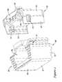
- FIG. 1is a perspective view of an exemplary intervertebral implant including an intervertebral spacer and a supplemental fixation structure;
- FIG. 2is an exploded view of the intervertebral spacer and the bone stabilization construct of the intervertebral implant of FIG. 1 ;
- FIG. 3is a top view of the intervertebral spacer and the bone stabilization construct of the intervertebral implant of FIG. 1 ;
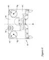
- FIG. 4is a perspective view of the bone stabilization construct of FIG. 1 with the retention member in a first, unlocked position;
- FIG. 5is a view generally along the central longitudinal axis of a first bone screw opening of the bone stabilization construct, with the retention member in a first, unlocked position;
- FIG. 6is a view generally along the central longitudinal axis of second and third bone screw openings of the bone stabilization construct, with the retention member in a first, unlocked position;
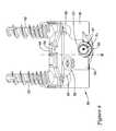
- FIG. 7is a perspective view of the bone stabilization construct of FIG. 1 with the retention member in a second, locked position;
- FIG. 8is a view generally along the central longitudinal axis of a first bone screw opening of the bone stabilization construct, with the retention member in a second, locked position;
- FIG. 9is a view generally along the central longitudinal axis of second and third bone screw openings of the bone stabilization construct, with the retention member in a second, locked position;
- FIG. 10is a top view of the bone stabilization construct with bone screws extending through the bone screw openings
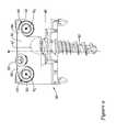
- FIG. 11is a perspective view of another exemplary intervertebral implant including an intervertebral spacer and a supplemental fixation structure;
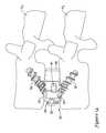
- FIGS. 12-14illustrate an illustrative method of installing the intervertebral implant to first and second vertebrae of a spinal column.
- FIG. 1An exemplary embodiment of an intervertebral implant 10 including an intervertebral spacer 20 and a supplemental fixation structure 35 is shown in FIG. 1 .
- the intervertebral implant 10may be configured to be secured between a first vertebra and a second vertebra of a spinal column, such as during a discectomy or corpectomy procedure.
- one or more, or a plurality of bone screws 32may be utilized to attach the intervertebral implant 10 to a vertebral body of a superior vertebra and one or more, or a plurality of bone screws 32 may be utilized to attach the intervertebral implant 10 to a vertebral body of an inferior vertebra.
- the intervertebral implant 10includes a bone stabilization construct 30 coupled to an intervertebral spacer 20 , however, in other embodiments the intervertebral implant 10 may include a bone stabilization construct 30 configured for securing to vertebrae of a spinal column without an intervertebral spacer 20 .
- the intervertebral spacer 20may be sized and configured to be positioned between a vertebral body of a superior vertebra and a vertebral body of an inferior vertebra during a discectomy or corpectomy procedure, for example, to maintain proper spacing between the vertebrae.
- the intervertebral spacer 20may include a posterior side 21 , an anterior side 24 opposite the posterior side 21 , lateral sides 22 , 23 extending between the posterior side 21 and the anterior side 24 , a superior side 25 configured to face or contact an inferior surface of a vertebral body of a superior vertebra, and a opposing inferior side 26 configured to face or contact a superior surface of a vertebral body of an inferior vertebra.
- the superior and/or inferior sides 25 , 26may include teeth, grooves or other anti-migration structures to engage the vertebral bodies to assist stabilizing the intervertebral spacer 20 between the vertebrae. Additionally, in some instances the intervertebral spacer 20 may include a cavity 28 , or a plurality of cavities, which may be filled with bone growth material to facilitate postoperative fusion between the superior and inferior vertebrae.
- the intervertebral spacer 20may be constructed of a polymer material, such as polyetheretherketone (PEEK), a metallic material, such as stainless steel or titanium, or any other suitable biocompatible material, as desired.
- PEEKpolyetheretherketone
- metallic materialsuch as stainless steel or titanium, or any other suitable biocompatible material, as desired.
- the supplemental fixation structure 35shown as a bone stabilization construct 30 may be coupled or couplable to the intervertebral spacer 20 .
- the bone stabilization construct 30may be a bone plate, or other structure configured to be secured to vertebrae or other bony structures.
- the bone stabilization construct 30may include a bone stabilization member 40 and a retention member 50 movably coupled to the bone stabilization member 40 .
- the retention member 50may be slidably coupled to the bone stabilization member 40 such that the retention member 50 is only permitted to slide in first and second opposite directions within a single plane.
- the bone stabilization member 40 and/or the retention membermay be constructed of a polymer material, such as polyetheretherketone (PEEK), a metallic material, such as stainless steel or titanium, or any other suitable biocompatible material, as desired.
- PEEKpolyetheretherketone
- metallic materialsuch as stainless steel or titanium, or any other suitable biocompatible material, as desired.
- the bone stabilization construct 30may be configured to be coupled to the intervertebral spacer 20 by any desired means.
- the bone stabilization member 40may include an engagement structure configured to engage or mate with an engagement structure of the intervertebral spacer 20 , or a fastener, such as a threaded fastener, may be used to couple the bone stabilization member 40 to the intervertebral spacer 20 .
- the bone stabilization member 40may be integrally coupled to the intervertebral spacer 20 by forming the bone stabilization member 40 and the intervertebral spacer 20 as a unitary structure, and movably coupling the retention member 50 to the bone stabilization member 40 of the unitary structure.
- the bone stabilization member 40may be configured to be snap fit to or otherwise interlock with an anterior portion of the intervertebral spacer 20 .
- the bone stabilization member 40may include first and second arms 42 configured to interlock in channels 29 of the intervertebral spacer 20 .
- a tang 41 on each arm 42which may be flexibly deflected relative to the arm 42 , may be configured to engage in opposing openings or notches 31 formed in the intervertebral spacer 20 to further interlock or engage the bone stabilization member 40 with the intervertebral spacer 20 .
- the tangs 41may be deflected outward as an anterior portion of the intervertebral spacer 20 is positioned between the arms 42 and then return to or toward an equilibrium position as the tangs 41 engage in the openings or notches 31 of the intervertebral spacer 20 .
- the bone stabilization member 40may include a plurality of openings to receive bone screws therethrough to secure the bone stabilization member 40 to vertebrae.
- the bone stabilization member 40may include a first bone screw opening 41 configured to receive a first bone screw 32 therethrough to anchor the bone stabilization member 40 to a first bony structure (e.g., a first, inferior vertebra), a second bone screw opening 42 configured to receive a second bone screw 32 therethrough to anchor the bone stabilization member 40 to a second bony structure (e.g., a second, superior vertebra), and a third bone screw opening 43 configured to receive a third bone screw 32 therethrough to anchor the bone stabilization member 40 to the second bony structure (e.g., the second, superior vertebra).
- a first bony structuree.g., a first, inferior vertebra
- a second bone screw opening 42configured to receive a second bone screw 32 therethrough to anchor the bone stabilization member 40 to a second bony structure (e.g., a second, superior vertebra)
- the second bone screw opening 42may be positioned proximate a first lateral edge of the bone stabilization member 40
- the third bone screw opening 43may be positioned proximate an opposite second lateral edge of the bone stabilization member 40
- the first bone screw opening 41may be positioned at a location intermediate the second bone screw opening 42 and the third bone screw opening 43 .
- the first, second and third bone screw openings 41 , 42 , 43may be arranged such that the first bone screw opening 41 is offset from, and not aligned between the second and third bone screw openings 42 , 43 .
- the first bone screw opening 41may be arranged so that a line extending between the central axes of the second and third bone screw openings 42 , 43 does not pass through the central axis of the first bone screw opening 41 .
- the central axis X 1 of the first bone screw opening 41may be offset from the midplane M of the intervertebral implant 10 , and thus the first bone screw opening 41 may be positioned closer to the central axis X 3 of the third bone screw opening 43 than to the central axis X 2 of the second bone screw opening 42 , while the central axes X 2 , X 3 of the second and third bone screw openings 42 , 43 may be spaced equidistant from the midplane M on either side of the midplane M.
- the midplane Mis an imaginary plane extending in a superior/inferior direction extending through the middle of the intervertebral implant 10 equidistant between lateral sides of the intervertebral spacer 20 .
- the retention member 50may be configured to be selectively actuatable between a first position (shown in FIGS. 4-6 ) permitting bone screws 32 to be inserted through the bone screw openings 41 , 42 , 43 and a second position (shown in FIGS. 7-9 ) preventing the bone screws 32 from backing out or being removed from the bone screw openings 41 , 42 , 43 once the bone stabilization member 40 is secured to the bony structures with the bone screws 32 .
- the retention member 50may be configured to simultaneously cover or be positioned over at least a portion of each of the bone screw openings 41 , 42 , 43 in the second, locked position, thus preventing each of the bone screws 32 from backing out.
- the retention member 50may be slidably coupled to the bone stabilization member 40 , permitting linear actuation of the retention member 50 relative to the bone stabilization member 40 along a longitudinal axis to slide the retention member 50 between the first, unlocked position and the second, locked position.
- the retention member 50may be linearly slidable between the first and second positions without rotational movement of the retention member 50 .
- a locking screw 52may be provided to couple the retention member 50 to the bone stabilization member 40 .
- the locking screw 52may extend through an elongated opening 56 of the retention member 50 and threadably engage a threaded bore 48 of the bone stabilization member 40 .
- the locking screw 52may be prevented from being fully unthreaded from the threaded bore 48 during use, thus insuring that the locking screw 52 will remain with the bone stabilization member 40 while the surgeon is installing the bone stabilization construct 30 to the bony structures.
- the elongated opening 56may have a length and a width, with the length being greater than the width. The locking screw 52 may be permitted to travel along the length of the elongated opening 56 as the retention member 50 is moved between the first position and the second position.
- the retention member 50may also include an engagement structure configured to mate with a complementary engagement structure of the bone stabilization member 40 .
- the retention member 50may include a protrusion 54 , such as a dovetail shaped protrusion, sized and configured to mate in a slot or channel 44 , such as a dovetail shaped slot or channel, in the bone stabilization member 40 .
- the protrusion 54may be configured to slide along the longitudinal axis of the channel 44 as the retention member 50 is linearly actuated between the first and second positions, without permitting the protrusion 54 from being uncoupled from the channel 44 .
- the protrusion 54may be T-shaped to mate with a T-shaped channel, or otherwise shaped to prohibit the protrusion 54 from being removed from the channel 54 in a direction perpendicular to the longitudinal axis of the channel 44 as the retention member 50 is linearly moved between the first and second positions. Engagement of the protrusion 54 within the channel 44 may permit the retention member 50 to move in first and second opposite directions relative to the bone stabilization member 40 along the longitudinal axis of the channel 44 , while prohibiting movement of the retention member 50 relative to the bone stabilization member 40 in all other directions.
- the protrusion 54 and the channel 44may be constructed such that the protrusion 54 is at least partially positioned in the channel 44 along the full length of travel of the locking screw 52 in the elongated opening 56 of the retention member 50 . Additionally, engagement of the protrusion 54 within the channel 44 may retain the retention member 50 in a desired orientation relative to the bone stabilization member 40 , as well as provide strength and/or stability to the portion of the retention member 50 located above the first bone screw opening 41 and extending toward the third bone screw opening 43 .
- the elongated opening 56may be configured such that as the locking screw 52 is tightened (e.g., rotation of the locking screw 52 causing the head of the locking screw 52 to bear against the retention member 50 ), the head of the locking screw 52 engages the rim of the elongated opening 56 .
- the locking screw 52may include a driver interface, such as a hex opening or other standard driver interface (or a specialized driver interface, if desired) to engage with a driver, such as a hex wrench or other standard driver (or a specialized driver) to tighten the locking screw 52 .
- a locking screw 52 having a standard driver interfacesuch as a hex opening
- a standard driver interfacesuch as a hex opening
- the head of the locking screw 52may interact with the rim of the elongate opening 56 such that when the head of the locking screw 52 is pressed against the rim, forces generated between the head of the locking screw 52 and the retention member 50 cause the retention member 50 to move toward the second position.
- the rim of the elongate opening 56may include a seating portion (visible in FIG. 4 ) in which the head of the locking screw 52 is seated when the retention member 50 is in the second position.
- the head of the locking screw 52moves toward and into the seating portion of the elongated opening 56 .
- the retention member 50may be firmly secured to the bone stabilization member 40 such that no further movement of the retention member 50 is permitted.
- FIG. 5illustrates a view of the bone stabilization construct 30 generally along the central longitudinal axis X 1 of the first bone screw opening 41 of the bone stabilization construct 30 , with the retention member 50 in the first, unlocked position.
- FIG. 6illustrates a view of the bone stabilization construct 30 generally along the central longitudinal axes X 2 , X 3 of the second and third bone screw openings 42 , 43 of the bone stabilization construct 30 , with the retention member 50 in the first, unlocked position. In the first position, the retention member 50 may be loosely coupled to the bone stabilization member 40 with the locking screw 52 and the protrusion 54 in the channel 44 .
- the retention member 50may be moved into the first position by raising the retention member 50 toward the upper side of the bone stabilization member 40 , and thus toward the superior side 25 of the intervertebral spacer 20 , such that the loosened locking screw 52 is moved into a lower portion of the elongated opening 56 .
- the first, second and third bone screws 32may be permitted to be inserted into the first, second and third bone screw openings 41 , 42 , 43 , respectively, without being inhibited by the retention member 50 .
- the retention member 50may be clear of and not cover or extend across any portion of any of the first, second and third bone screw openings 41 , 42 , 43 or otherwise may not substantially block any of the first, second and third bone screw openings 41 , 42 , 43 , and thus permit the first, second and third bone screws 32 to be inserted into the first, second and third bone screw openings 41 , 42 , 43 , respectively.
- all portions of the retention member 50may be located radially outward of and not impede into the diameter of any of the first, second and third bone screw openings 41 , 42 , 43 , for example.
- FIG. 7illustrates the bone stabilization construct 30 with the retention member 50 moved downward to the second position upon tightening the locking screw 52 .
- the locking screw 52may travel in the elongated opening 56 toward the seating portion of the elongated opening 56 at the upper extent of the elongated opening 56 .
- portions of the retention member 50may cover or extend across portions of each of the first, second and third bone screw openings 41 , 42 , 43 and thus the heads of respective bone screws 32 extending therethrough to prevent the bone screws 32 from backing out of the bone screw openings 41 , 42 , 43 .
- the retention member 50may include a first portion, such as an arcuate edge 57 defining an arcuate cutout portion of the retention member 50 at least partially covering the first bone screw opening 41 (and associated bone screw 32 ), a second portion, such as a first tab 58 , at least partially covering the second bone screw opening 42 (and associated bone screw 32 ), and a third portion, such as a second tab 59 , at least partially covering the third bone screw opening 43 (and associated bone screw 32 ).
- a first portionsuch as an arcuate edge 57 defining an arcuate cutout portion of the retention member 50 at least partially covering the first bone screw opening 41 (and associated bone screw 32 )
- a second portionsuch as a first tab 58
- a third portionsuch as a second tab 59
- FIG. 8illustrates a view of the bone stabilization construct 30 generally along the central longitudinal axis X 1 of the first bone screw opening 41 of the bone stabilization construct 30 , with the retention member 50 in the second, locked position.
- FIG. 9illustrates a view of the bone stabilization construct 30 generally along the central longitudinal axes X 2 , X 3 of the second and third bone screw openings 42 , 43 of the bone stabilization construct 30 , with the retention member 50 in the second, locked position.
- the retention member 50fixedly secured to the bone stabilization member 40 via tightening the locking screw 52 , may at least partially cover each of the first, second and third bone screw openings 41 , 42 , 43 to prevent a bone screw 32 from backing out of the respective bone screw opening.
- a portion of the retention member 50may be located radially inward of and impede into the diameter of each of the first, second and third bone screw openings 41 , 42 , 43 .
- the second and third bone screw openings 42 , 43may be configured such that the central axis of the associated bone screws 32 extend along the central axis of the second and third bone screw openings 42 , 43 generally parallel to the midplane M of the intervertebral implant 10 . Since the first bone screw opening 41 is offset from the midplane M, the first bone screw opening 41 may be configured to angle the distal tip of the bone screw 32 extending therethrough toward the midplane M from the first bone screw opening 41 .
- the first bone screw opening 41may be configured such that the central axis of the first bone screw 32 , which may be coaxial with the central axis X 1 of the first bone screw opening 41 , may be at an angle ⁇ to the midplane M.
- the central axis of the first bone screw 32may extend at an angle ⁇ in the range of about 1 to 10 degrees, for example, about 1, about 2, about 3, about 4, about 5, about 6, about 7, about 8, about 9 or about 10 degrees from the midplane M, if desired, in order to angle the distal tip of the bone screw 32 toward the midplane M.
- intervertebral implant 110is shown in FIG. 11 .
- the intervertebral implant 110may share many similarities to the intervertebral implant 10 .
- the intervertebral implant 110may include an intervertebral spacer 120 and a supplemental fixation structure 135 to facilitate securement of the intervertebral implant 110 between a first vertebra and a second vertebra of a spinal column.
- one or more, or a plurality of bone screws 132may be utilized to attach the intervertebral implant 110 to a vertebral body of a superior vertebra and one or more, or a plurality of bone screws 132 may be utilized to attach the intervertebral implant 110 to a vertebral body of an inferior vertebra.
- the supplemental fixation structure 135shown as a bone stabilization construct 130 may be coupled or couplable to the intervertebral spacer 120 .
- the bone stabilization construct 130may include a bone stabilization member 140 and a retention member 150 movably coupled to the bone stabilization member 140 .
- the retention member 150may be slidably coupled to the bone stabilization member 140 such that the retention member 150 is only permitted to slide linearly in first and second opposite directions within a single plane.
- a locking screw 152may be provided to couple the retention member 150 to the bone stabilization member 140 .
- the locking screw 152may extend through an elongated opening 156 of the retention member 150 and threadably engage a threaded bore of the bone stabilization member 140 .
- the head of the locking screw 152may interact with the rim of the elongate opening 156 such that when the head of the locking screw 152 is pressed against the rim, forces generated between the head of the locking screw 152 and the retention member 150 cause the retention member 150 to move from the first, unlocked position toward the second, locked position to prevent the bone screws 132 from backing out.
- FIG. 11illustrates a configuration of an intervertebral implant 110 having a height less than the height of the intervertebral implant 10 shown in FIG. 1 .
- offsetting the first bone screw opening 141 from the midplane M of the intervertebral implant 110 to a first side of the midplane M, while offsetting the locking screw 152 and associated elongated opening 156 to a second side of the midplane M opposite the first bone screw opening 141may permit the construction of intervertebral implants having a smaller height dimension than the combined heights of the elongated opening 156 and the first bone screw opening 141 .
- a set of intervertebral implants having a range of heightsmay be provided during a surgical procedure, including heights less than the combined heights of the elongated opening 156 and the first bone screw opening 141 without reducing the size of the locking screw 152 and/or the bone screws 132 .
- FIGS. 12-14illustrate one exemplary method of installing the intervertebral implant 10 to first and second vertebrae V 1 , V 2 of a spinal column.
- the intervertebral implant 10may maintain the proper spacing and/or lordosis between the vertebrae V 1 , V 2 and restore stability to the spine.
- the intervertebral implant 10may be provided with the bone stabilization construct 30 coupled to the intervertebral spacer 20 . If not already coupled to the intervertebral spacer 20 , the bone stabilization construct 30 may be intraoperatively coupled to the intervertebral spacer 20 prior to installing the intervertebral implant 10 . It is noted that in some instances, the bone stabilization construct 30 may be coupled to or otherwise interlocked with the intervertebral spacer 20 subsequent to installing the intervertebral spacer 20 between the vertebrae V 1 , V 2 , if desired. The bone stabilization construct 30 may be coupled to the anterior portion of the intervertebral spacer 20 .
- the bone stabilization member 40may be snap coupled to the intervertebral spacer 20 such that the first and second arms 42 of the bone stabilization member 40 are positioned on either side of the anterior portion and the tangs 41 are engaged in the openings or notches 31 of the intervertebral spacer 20 .
- the intervertebral spacer 20 and the bone stabilization construct 30 of the intervertebral implant 10may be inserted between the vertebral body of the first vertebra V 1 and the vertebral body of the second vertebra V 2 using an insertion instrument (not shown).
- the intervertebral implant 10may be inserted using an anterior approach, in which the posterior side of the intervertebral spacer 20 , which may be considered the leading side, is inserted first and directed posteriorly into the space between the vertebrae V 1 , V 2 , from the anterior side of the spinal column.
- the inferior surface of the intervertebral spacer 20may be configured to engage a superior surface of the vertebral body of the first vertebra V 1 and the superior surface of the intervertebral spacer 20 may be configured to engage an inferior surface of the vertebral body of the second vertebra V 2 .
- the superior and inferior surfacesmay be generally parallel, disposed at an angle, or have a curvature to accommodate the proper spacing and/or lordosis between the vertebrae V 1 , V 2 .
- the cavity 28may be filled with bone growth material prior to inserting the intervertebral spacer 20 to promote subsequent fusion between the vertebrae V 1 , V 2 .
- bone screws 32may be inserted through the bone screw openings 41 , 42 , 43 of the bone stabilization member 40 and screwed into the vertebrae V 1 , V 2 while the retention member 50 is in the first, unlocked position.
- a first bone screw 32may be inserted through the first bone screw opening 41 of the bone stabilization member 40 with the retention member 50 coupled to the bone stabilization member 40 in the first position.
- the first bone screw 32may be screwed into the vertebral body of the first vertebra V 1 to anchor the bone stabilization member 40 to the first vertebra V 1 .
- a second bone screw 32may be inserted through the second bone screw opening 42 of the bone stabilization member 40 and a third bone screw 32 may be inserted through the third bone screw opening 43 with the retention member 50 coupled to the bone stabilization member 40 in the first position.
- the second and third bone screws 32may be screwed into the vertebral body of the second vertebra V 2 to anchor the bone stabilization member 40 to the second vertebra V 2 .
- the retention member 50may be moved to the second position to extend across at least a portion of each of the first, second and third bone screw openings 41 , 42 , 43 to prevent the bone screws 32 from backing out of the bones.
- the retention member 50may be slid linearly relative to the bone stabilization member 40 from the first position to the second position while coupled to the bone stabilization member 40 , and thereafter locked in the second position.
- the locking screw 52may be tightened (e.g. rotated with a driver).
- the locking screw 52may exert a force on the rim of the elongated opening 56 of the retention member 50 to slide the retention member 50 linearly from the first position to the second position.
- the protrusion 54may follow along the channel 44 of the bone stabilization member 40 as the retention member 50 moves toward the second position.
- the locking screw 52may be rotated until the locking screw 52 has traveled along the length of the elongated opening 56 a sufficient distance such that the head of the locking screw 52 is seated in the seating portion of the elongate opening 56 . Sufficient torque may be applied to the locking screw 52 to securely seat the head of the locking screw 52 in the seating portion and secure the retention member 50 from further movement relative to the bone stabilization member 40 .
- the retention member 50may prevent each of the first, second and third bone screws 32 from being removed from the first, second and third bone screw openings 41 , 42 , 43 , respectively.
- the bone stabilization construct 30 , 130may be used in other applications, such as trauma to secure two bony structures (e.g. two bony portions of a single bone, or a first bone and a second bone) with a plurality of bone screws 32 , 132 .
- the bone stabilization construct 30 , 130may be used without the intervertebral spacer 20 , 120 .
- the bone stabilization member 30 , 130may be secured to two bony structures with a first bone screw 32 , 132 screwed into a first bony structure and second and third bone screws 32 , 132 screwed into a second bony structure.
Landscapes
- Health & Medical Sciences (AREA)
- Orthopedic Medicine & Surgery (AREA)
- Engineering & Computer Science (AREA)
- Biomedical Technology (AREA)
- Neurology (AREA)
- Life Sciences & Earth Sciences (AREA)
- General Health & Medical Sciences (AREA)
- Veterinary Medicine (AREA)
- Heart & Thoracic Surgery (AREA)
- Public Health (AREA)
- Animal Behavior & Ethology (AREA)
- Surgery (AREA)
- Cardiology (AREA)
- Vascular Medicine (AREA)
- Transplantation (AREA)
- Oral & Maxillofacial Surgery (AREA)
- Nuclear Medicine, Radiotherapy & Molecular Imaging (AREA)
- Medical Informatics (AREA)
- Molecular Biology (AREA)
- Prostheses (AREA)
- Surgical Instruments (AREA)
Abstract
Description
Claims (9)
Priority Applications (7)
| Application Number | Priority Date | Filing Date | Title |
|---|---|---|---|
| US13/560,598US8814912B2 (en) | 2012-07-27 | 2012-07-27 | Bone stabilization member with bone screw retention mechanism |
| AU2013206566AAU2013206566B2 (en) | 2012-07-27 | 2013-06-27 | Bone stabilization member with bone screw retention mechanism |
| EP19158117.2AEP3622909A1 (en) | 2012-07-27 | 2013-07-18 | Bone stabilization member with bone screw retention mechanism |
| EP13177141.2AEP2689736B1 (en) | 2012-07-27 | 2013-07-18 | Bone stabilization member with bone screw retention mechanism |
| US14/332,851US9414937B2 (en) | 2012-07-27 | 2014-07-16 | Bone stabilization member with bone screw retention mechanism |
| US15/210,615US9937056B2 (en) | 2012-07-27 | 2016-07-14 | Bone stabilization member with bone screw retention mechanism |
| US15/917,112US20180193163A1 (en) | 2012-07-27 | 2018-03-09 | Bone stabilization member with bone screw retention mechanism |
Applications Claiming Priority (1)
| Application Number | Priority Date | Filing Date | Title |
|---|---|---|---|
| US13/560,598US8814912B2 (en) | 2012-07-27 | 2012-07-27 | Bone stabilization member with bone screw retention mechanism |
Related Child Applications (1)
| Application Number | Title | Priority Date | Filing Date |
|---|---|---|---|
| US14/332,851ContinuationUS9414937B2 (en) | 2012-07-27 | 2014-07-16 | Bone stabilization member with bone screw retention mechanism |
Publications (2)
| Publication Number | Publication Date |
|---|---|
| US20140031869A1 US20140031869A1 (en) | 2014-01-30 |
| US8814912B2true US8814912B2 (en) | 2014-08-26 |
Family
ID=48793989
Family Applications (4)
| Application Number | Title | Priority Date | Filing Date |
|---|---|---|---|
| US13/560,598ActiveUS8814912B2 (en) | 2012-07-27 | 2012-07-27 | Bone stabilization member with bone screw retention mechanism |
| US14/332,851Active2032-08-18US9414937B2 (en) | 2012-07-27 | 2014-07-16 | Bone stabilization member with bone screw retention mechanism |
| US15/210,615Expired - Fee RelatedUS9937056B2 (en) | 2012-07-27 | 2016-07-14 | Bone stabilization member with bone screw retention mechanism |
| US15/917,112AbandonedUS20180193163A1 (en) | 2012-07-27 | 2018-03-09 | Bone stabilization member with bone screw retention mechanism |
Family Applications After (3)
| Application Number | Title | Priority Date | Filing Date |
|---|---|---|---|
| US14/332,851Active2032-08-18US9414937B2 (en) | 2012-07-27 | 2014-07-16 | Bone stabilization member with bone screw retention mechanism |
| US15/210,615Expired - Fee RelatedUS9937056B2 (en) | 2012-07-27 | 2016-07-14 | Bone stabilization member with bone screw retention mechanism |
| US15/917,112AbandonedUS20180193163A1 (en) | 2012-07-27 | 2018-03-09 | Bone stabilization member with bone screw retention mechanism |
Country Status (3)
| Country | Link |
|---|---|
| US (4) | US8814912B2 (en) |
| EP (2) | EP2689736B1 (en) |
| AU (1) | AU2013206566B2 (en) |
Cited By (9)
| Publication number | Priority date | Publication date | Assignee | Title |
|---|---|---|---|---|
| US20150142114A1 (en)* | 2013-11-21 | 2015-05-21 | Perumala Corporation | Intervertebral Disk Cage and Stabilizer |
| US9119682B2 (en)* | 2010-03-03 | 2015-09-01 | Lanx, Inc. | Bone plating system and method |
| US20150328007A1 (en)* | 2014-05-15 | 2015-11-19 | Globus Medical, Inc | Standalone Interbody Implants |
| US9364340B2 (en)* | 2013-03-05 | 2016-06-14 | Globus Medical, Inc. | Low profile plate |
| US9937056B2 (en) | 2012-07-27 | 2018-04-10 | Zimmer Spine, Inc. | Bone stabilization member with bone screw retention mechanism |
| US10492912B2 (en) | 2017-08-18 | 2019-12-03 | Innovasis, Inc. | Interbody spinal fusion implant having locking elements with lateral displacement |
| US10555764B2 (en) | 2017-08-22 | 2020-02-11 | Innovasis, Inc. | Interbody spinal fusion implant having locking elements that outwardly displace for locking |
| KR20200024878A (en) | 2017-06-30 | 2020-03-09 | 엘리베이션 스파인 주식회사 | Interbody spacer and bone plate assembly, instrument and method of use thereof |
| US11491025B2 (en) | 2016-10-25 | 2022-11-08 | Elevation Spine, Inc. | Intervertebral implant and method of use |
Families Citing this family (32)
| Publication number | Priority date | Publication date | Assignee | Title |
|---|---|---|---|---|
| US9561060B2 (en)* | 2007-11-02 | 2017-02-07 | Zimmer Biomet Spine, Inc. | Interspinous implants with adjustable height spacer |
| US9237957B2 (en)* | 2011-09-16 | 2016-01-19 | Globus Medical, Inc. | Low profile plate |
| US9539109B2 (en) | 2011-09-16 | 2017-01-10 | Globus Medical, Inc. | Low profile plate |
| PL2740449T3 (en) | 2012-12-10 | 2019-07-31 | The Procter & Gamble Company | Absorbent article with high absorbent material content |
| US11311312B2 (en) | 2013-03-15 | 2022-04-26 | Medtronic, Inc. | Subcutaneous delivery tool |
| US10105169B2 (en) | 2015-11-13 | 2018-10-23 | Leith Medical LLC | Bone fixation systems, apparatuses, and methods with anti-back-out feature |
| US11806250B2 (en) | 2018-02-22 | 2023-11-07 | Warsaw Orthopedic, Inc. | Expandable spinal implant system and method of using same |
| CN111655203A (en) | 2018-02-22 | 2020-09-11 | 华沙整形外科股份有限公司 | Expandable spinal implant system and method of use |
| EP3755273B1 (en) | 2018-02-22 | 2025-04-30 | Warsaw Orthopedic, Inc. | Expandable spinal implant system |
| USD948048S1 (en) | 2019-04-26 | 2022-04-05 | Warsaw Orthopedic, Inc. | Surgical implant |
| USD955579S1 (en) | 2019-04-26 | 2022-06-21 | Warsaw Orthopedic, Inc. | Surgical implant |
| MX2022004471A (en) | 2019-10-14 | 2022-08-16 | Leith Medical LLC | A BONE FIXATION SYSTEM WITH FASTENERS AND A REMOVAL TOOL TO DECOUPLATE FROM THE FASTENERS. |
| CA3157932A1 (en) | 2019-10-14 | 2021-04-22 | Leith Medical, LLC | Apparatus for stablization of a bone fracture site |
| US11376134B1 (en) | 2020-11-05 | 2022-07-05 | Warsaw Orthopedic, Inc. | Dual expanding spinal implant, system, and method of use |
| US11395743B1 (en) | 2021-05-04 | 2022-07-26 | Warsaw Orthopedic, Inc. | Externally driven expandable interbody and related methods |
| US12171439B2 (en) | 2020-11-05 | 2024-12-24 | Warsaw Orthopedic, Inc. | Protected drill |
| US12239544B2 (en) | 2020-11-05 | 2025-03-04 | Warsaw Orthopedic, Inc. | Rhomboid shaped implants |
| US11517443B2 (en) | 2020-11-05 | 2022-12-06 | Warsaw Orthopedic, Inc. | Dual wedge expandable implant, system and method of use |
| US12318308B2 (en) | 2020-11-05 | 2025-06-03 | Warsaw Orthopedic, Inc. | Dual expandable inter-body device |
| US11638653B2 (en) | 2020-11-05 | 2023-05-02 | Warsaw Orthopedic, Inc. | Surgery instruments with a movable handle |
| US11517363B2 (en) | 2020-11-05 | 2022-12-06 | Warsaw Orthopedic, Inc. | Screw driver and complimentary screws |
| US11285014B1 (en) | 2020-11-05 | 2022-03-29 | Warsaw Orthopedic, Inc. | Expandable inter-body device, system, and method |
| US11291554B1 (en) | 2021-05-03 | 2022-04-05 | Medtronic, Inc. | Unibody dual expanding interbody implant |
| US11833059B2 (en) | 2020-11-05 | 2023-12-05 | Warsaw Orthopedic, Inc. | Expandable inter-body device, expandable plate system, and associated methods |
| US12121453B2 (en) | 2020-11-05 | 2024-10-22 | Warsaw Orthopedic, Inc. | Dual wedge expandable implant with eyelets, system, and method of use |
| US11963881B2 (en) | 2020-11-05 | 2024-04-23 | Warsaw Orthopedic, Inc. | Expandable inter-body device, system, and method |
| US12295865B2 (en) | 2021-06-24 | 2025-05-13 | Warsaw Orthopedic, Inc. | Expandable interbody implant and corresponding inserter |
| US11612499B2 (en) | 2021-06-24 | 2023-03-28 | Warsaw Orthopedic, Inc. | Expandable interbody implant |
| WO2022271280A1 (en) | 2021-06-24 | 2022-12-29 | Warsaw Orthopedic, Inc. | Expandable interbody implant and corresponding surgical tool |
| US12268614B2 (en) | 2021-06-24 | 2025-04-08 | Warsaw Orthopedic, Inc. | Interbody implant with adjusting shims |
| US11730608B2 (en) | 2021-07-13 | 2023-08-22 | Warsaw Orthopedic, Inc. | Monoblock expandable interbody implant |
| US11850163B2 (en) | 2022-02-01 | 2023-12-26 | Warsaw Orthopedic, Inc. | Interbody implant with adjusting shims |
Citations (155)
| Publication number | Priority date | Publication date | Assignee | Title |
|---|---|---|---|---|
| US4714469A (en) | 1987-02-26 | 1987-12-22 | Pfizer Hospital Products Group, Inc. | Spinal implant |
| US4743256A (en) | 1985-10-04 | 1988-05-10 | Brantigan John W | Surgical prosthetic implant facilitating vertebral interbody fusion and method |
| US4904261A (en) | 1987-08-06 | 1990-02-27 | A. W. Showell (Surgicraft) Limited | Spinal implants |
| US4955908A (en) | 1987-07-09 | 1990-09-11 | Sulzer Brothers Limited | Metallic intervertebral prosthesis |
| US5171278A (en) | 1991-02-22 | 1992-12-15 | Madhavan Pisharodi | Middle expandable intervertebral disk implants |
| US5258031A (en) | 1992-01-06 | 1993-11-02 | Danek Medical | Intervertebral disk arthroplasty |
| US5390683A (en) | 1991-02-22 | 1995-02-21 | Pisharodi; Madhavan | Spinal implantation methods utilizing a middle expandable implant |
| US5397364A (en) | 1993-10-12 | 1995-03-14 | Danek Medical, Inc. | Anterior interbody fusion device |
| US5554191A (en) | 1994-01-26 | 1996-09-10 | Biomat | Intersomatic vertebral cage |
| US5571109A (en) | 1993-08-26 | 1996-11-05 | Man Ceramics Gmbh | System for the immobilization of vertebrae |
| US5609635A (en) | 1988-06-28 | 1997-03-11 | Michelson; Gary K. | Lordotic interbody spinal fusion implants |
| US5658335A (en) | 1995-03-09 | 1997-08-19 | Cohort Medical Products Group, Inc. | Spinal fixator |
| US5683394A (en) | 1995-09-29 | 1997-11-04 | Advanced Spine Fixation Systems, Inc. | Fusion mass constrainer |
| US5713899A (en) | 1995-04-27 | 1998-02-03 | Societe Jbs Sa | Cervical cage designed for the performance of intersomatic arthrodesis |
| US5800550A (en) | 1996-03-13 | 1998-09-01 | Sertich; Mario M. | Interbody fusion cage |
| US5800547A (en) | 1994-08-20 | 1998-09-01 | Schafer Micomed Gmbh | Ventral intervertebral implant |
| US5888223A (en) | 1995-12-08 | 1999-03-30 | Bray, Jr.; Robert S. | Anterior stabilization device |
| US5976139A (en) | 1996-07-17 | 1999-11-02 | Bramlet; Dale G. | Surgical fastener assembly |
| WO1999056653A1 (en) | 1998-04-30 | 1999-11-11 | Societe De Fabrication De Materiel Orthopedique (Sofamor) | Bone plate with bone screw securing means |
| US6066175A (en) | 1993-02-16 | 2000-05-23 | Henderson; Fraser C. | Fusion stabilization chamber |
| US6077264A (en) | 1996-04-05 | 2000-06-20 | Chemello; Antonio | Intramedullary nail for the osteosynthesis of bone fractures |
| US6096080A (en) | 1998-05-06 | 2000-08-01 | Cortek, Inc. | Apparatus for spinal fusion using implanted devices |
| US6099531A (en) | 1998-08-20 | 2000-08-08 | Bonutti; Peter M. | Changing relationship between bones |
| US6113638A (en) | 1999-02-26 | 2000-09-05 | Williams; Lytton A. | Method and apparatus for intervertebral implant anchorage |
| US6120503A (en) | 1994-03-28 | 2000-09-19 | Michelson; Gary Karlin | Apparatus instrumentation, and method for spinal fixation |
| US6156037A (en) | 1998-10-28 | 2000-12-05 | Sdgi Holdings, Inc. | Anterior lateral spine cage-plate fixation device and technique |
| US6179873B1 (en) | 1995-08-11 | 2001-01-30 | Bernhard Zientek | Intervertebral implant, process for widening and instruments for implanting an intervertebral implant |
| US6190413B1 (en) | 1998-04-16 | 2001-02-20 | Ulrich Gmbh & Co. Kg | Vertebral implant |
| US6193721B1 (en) | 1997-02-11 | 2001-02-27 | Gary K. Michelson | Multi-lock anterior cervical plating system |
| US6231610B1 (en) | 1999-08-25 | 2001-05-15 | Allegiance Corporation | Anterior cervical column support device |
| US6235059B1 (en) | 1996-04-03 | 2001-05-22 | Scient'x (Societe A Responsabilite Limitee) | Intersomatic setting and fusion system |
| US6306136B1 (en) | 1997-07-28 | 2001-10-23 | Dimso (Distribution Medicales Du Sud-Ouest) | Implant, in particular front cervical plate |
| US20010034553A1 (en) | 2000-02-04 | 2001-10-25 | Michelson Gary Karlin | Expandable push-in arcuate interbody spinal fusion implant with tapered configuration during insertion |
| US6371989B1 (en) | 1996-09-13 | 2002-04-16 | Jean-Luc Chauvin | Method of providing proper vertebral spacing |
| US20020052656A1 (en) | 2000-02-04 | 2002-05-02 | Michelson Gary Karlin | Expandable push-in interbody spinal fusion implant |
| US20020072801A1 (en) | 2000-02-04 | 2002-06-13 | Michelson Gary K. | Expandable threaded arcuate interbody spinal fusion implant with lordotic configuration during insertion |
| US6432106B1 (en) | 1999-11-24 | 2002-08-13 | Depuy Acromed, Inc. | Anterior lumbar interbody fusion cage with locking plate |
| US6443954B1 (en) | 2001-04-24 | 2002-09-03 | Dale G. Bramlet | Femoral nail intramedullary system |
| US6447546B1 (en) | 2000-08-11 | 2002-09-10 | Dale G. Bramlet | Apparatus and method for fusing opposing spinal vertebrae |
| US20020128717A1 (en) | 2000-03-09 | 2002-09-12 | Alfaro Arthur A. | Anterior lumbar spacer |
| US20020143399A1 (en) | 2001-04-02 | 2002-10-03 | Ulrich Gmbh & Co. Kg | Anchorable vertebral implant |
| US6461359B1 (en) | 1999-11-10 | 2002-10-08 | Clifford Tribus | Spine stabilization device |
| US6468309B1 (en) | 2000-10-05 | 2002-10-22 | Cleveland Clinic Foundation | Method and apparatus for stabilizing adjacent bones |
| US6471724B2 (en) | 1995-03-27 | 2002-10-29 | Sdgi Holdings, Inc. | Methods and instruments for interbody fusion |
| US6482233B1 (en) | 1998-01-29 | 2002-11-19 | Synthes(U.S.A.) | Prosthetic interbody spacer |
| US6500205B1 (en) | 2000-04-19 | 2002-12-31 | Gary K. Michelson | Expandable threaded arcuate interbody spinal fusion implant with cylindrical configuration during insertion |
| US6503250B2 (en) | 2000-11-28 | 2003-01-07 | Kamaljit S. Paul | Bone support assembly |
| US6533786B1 (en) | 1999-10-13 | 2003-03-18 | Sdgi Holdings, Inc. | Anterior cervical plating system |
| US6558423B1 (en) | 1999-05-05 | 2003-05-06 | Gary K. Michelson | Interbody spinal fusion implants with multi-lock for locking opposed screws |
| US6579290B1 (en) | 1997-11-29 | 2003-06-17 | Surgicraft Limited | Surgical implant and surgical fixing screw |
| US6602255B1 (en) | 2000-06-26 | 2003-08-05 | Stryker Spine | Bone screw retaining system |
| US6610093B1 (en) | 2000-07-28 | 2003-08-26 | Perumala Corporation | Method and apparatus for stabilizing adjacent vertebrae |
| US6626907B2 (en) | 1998-05-19 | 2003-09-30 | Alphatec Manufacturing, Inc. | Anterior cervical plate and fixation system |
| US6629998B1 (en) | 2000-08-23 | 2003-10-07 | Chih-I Lin | Intervertebral retrieval device |
| US20030195632A1 (en) | 2001-02-06 | 2003-10-16 | Foley Kevin T. | Spinal implant with attached ligament |
| US20030208275A1 (en) | 2000-02-04 | 2003-11-06 | Michelson Gary K. | Expandable push-in interbody spinal fusion implant |
| US6695846B2 (en) | 2002-03-12 | 2004-02-24 | Spinal Innovations, Llc | Bone plate and screw retaining mechanism |
| US6716245B2 (en) | 2000-07-12 | 2004-04-06 | Spine Next | Intersomatic implant |
| US6723126B1 (en) | 2002-11-01 | 2004-04-20 | Sdgi Holdings, Inc. | Laterally expandable cage |
| US20040078078A1 (en) | 2002-10-18 | 2004-04-22 | Shepard Yolanda Denise | Cortical and cancellous allograft cervical fusion block |
| US6730127B2 (en) | 2000-07-10 | 2004-05-04 | Gary K. Michelson | Flanged interbody spinal fusion implants |
| US6740088B1 (en) | 2000-10-25 | 2004-05-25 | Sdgi Holdings, Inc. | Anterior lumbar plate and method |
| US6743256B2 (en) | 2000-10-11 | 2004-06-01 | Michael D. Mason | Graftless spinal fusion device |
| US6770096B2 (en) | 1999-07-01 | 2004-08-03 | Spinevision S.A. | Interbody spinal stabilization cage and spinal stabilization method |
| US6800093B2 (en) | 1998-05-06 | 2004-10-05 | Cortek, Inc. | Device for spinal fusion |
| US20040210310A1 (en) | 2002-12-10 | 2004-10-21 | Trieu Hai H. | Implant system and method for intervertebral disc augmentation |
| US6808537B2 (en) | 2000-07-07 | 2004-10-26 | Gary Karlin Michelson | Expandable implant with interlocking walls |
| US6824564B2 (en) | 1997-04-25 | 2004-11-30 | Stryker France, Sas | Two-part intersomatic implant |
| US20040254644A1 (en) | 2002-10-21 | 2004-12-16 | Taylor Brett Allison | Intervertebral disk prosthesis |
| US6837905B1 (en) | 2002-09-26 | 2005-01-04 | Daniel M. Lieberman | Spinal vertebral fusion implant and method |
| US20050049590A1 (en) | 2003-03-07 | 2005-03-03 | Neville Alleyne | Spinal implant with securement spikes |
| US6884242B2 (en) | 2001-04-06 | 2005-04-26 | Society De Fabrication De Materiel Orthopedique, S.A. | Anterior plating system and method |
| US6890355B2 (en) | 2001-04-02 | 2005-05-10 | Gary K. Michelson | Artificial contoured spinal fusion implants made of a material other than bone |
| US20050177236A1 (en) | 2002-02-19 | 2005-08-11 | Claude Mathieu | Intervertebral implant |
| US6945973B2 (en) | 2003-05-01 | 2005-09-20 | Nuvasive, Inc. | Slidable bone plate system |
| US6955691B2 (en) | 2003-11-21 | 2005-10-18 | Kyungwon Medical Co., Ltd. | Expandable interfusion cage |
| US6972019B2 (en) | 2001-01-23 | 2005-12-06 | Michelson Gary K | Interbody spinal implant with trailing end adapted to receive bone screws |
| US6974479B2 (en) | 2002-12-10 | 2005-12-13 | Sdgi Holdings, Inc. | System and method for blocking and/or retaining a prosthetic spinal implant |
| US6984234B2 (en) | 2003-04-21 | 2006-01-10 | Rsb Spine Llc | Bone plate stabilization system and method for its use |
| US20060030851A1 (en) | 2003-04-21 | 2006-02-09 | Rsb Spine Llc | Implant subsidence control |
| US7001387B2 (en) | 1997-05-15 | 2006-02-21 | Sdgi Holdings, Inc. | Anterior cervical plating system |
| US7004944B2 (en) | 2002-07-16 | 2006-02-28 | Sdgi Holdings, Inc. | Bone plate fastener retaining mechanisms and methods |
| US7018414B2 (en) | 2002-07-30 | 2006-03-28 | Brau Salvador A | Support device for vertebral fusion |
| US7044952B2 (en) | 2001-06-06 | 2006-05-16 | Sdgi Holdings, Inc. | Dynamic multilock anterior cervical plate system having non-detachably fastened and moveable segments |
| US7060067B2 (en) | 2002-08-16 | 2006-06-13 | Sdgi Holdings, Inc. | Systems, instrumentation and techniques for retaining fasteners relative to a bone plate |
| US7070598B2 (en) | 2002-06-25 | 2006-07-04 | Sdgi Holdings, Inc. | Minimally invasive expanding spacer and method |
| US7077864B2 (en) | 2002-02-12 | 2006-07-18 | Cross Medical Products, Inc. | Vertebral interbody cage with translatable locking screw |
| US20060173543A1 (en) | 2002-07-30 | 2006-08-03 | Brau Salvador A | Support device for vertebral fusion |
| US7087243B2 (en) | 1997-09-09 | 2006-08-08 | Edgren David E | Pharmaceutical coating composition and method of use |
| US7112222B2 (en) | 2003-03-31 | 2006-09-26 | Depuy Spine, Inc. | Anterior lumbar interbody fusion cage with locking plate |
| US7115130B2 (en) | 2001-06-06 | 2006-10-03 | Warsaw Orthopedic, Inc. | Method for installing dynamic, modular, multilock anterior cervical plate system having detachably fastened assembleable and moveable segments |
| US20060241621A1 (en) | 2005-04-12 | 2006-10-26 | Moskowitz Mosheh T | Bi-directional fixating transvertebral body screws, zero-profile horizontal intervertebral miniplates, expansile intervertebral body fusion devices, and posterior motion-calibrating interarticulating joint stapling device for spinal fusion |
| US20060247770A1 (en) | 2005-04-29 | 2006-11-02 | Sdgi Holdings, Inc. | Expandable intervertebral implant and associated instrumentation |
| US7135024B2 (en) | 1999-09-03 | 2006-11-14 | Cookgas, L.L.C. | Lumbar spine fixation device |
| US7166110B2 (en) | 2004-01-09 | 2007-01-23 | Yundt Kent D | Method, system and apparatus for interbody fusion |
| US7172627B2 (en) | 2001-04-03 | 2007-02-06 | Scient'x | Stabilized interbody fusion system for vertebrae |
| US7182782B2 (en) | 2003-09-30 | 2007-02-27 | X-Spine Systems, Inc. | Spinal fusion system and method for fusing spinal bones |
| US20070049943A1 (en) | 2005-04-12 | 2007-03-01 | Nathan Moskowitz | Bi-directional fixating transvertebral body screws, zero-profile horizontal intervertebral miniplates, total intervertebral body fusion devices, and posterior motion-calibrating interarticulating joint stapling device for spinal fusion |
| US20070106384A1 (en) | 2003-04-21 | 2007-05-10 | Rsb Spine Llc | Implant subsidence control |
| US7217293B2 (en) | 2003-11-21 | 2007-05-15 | Warsaw Orthopedic, Inc. | Expandable spinal implant |
| US20070233253A1 (en) | 2003-04-21 | 2007-10-04 | Bray Robert S | Lateral mount implant device |
| US20070250167A1 (en) | 2003-04-21 | 2007-10-25 | Rsb Spine Llc | Spine implants |
| US7291170B2 (en) | 2000-05-18 | 2007-11-06 | Ldr Medical | Intersomatic cage with unified grafts |
| US7297162B2 (en) | 2004-06-09 | 2007-11-20 | Zimmer Spine, Inc. | Expandable helical cage |
| US7309340B2 (en) | 2003-06-20 | 2007-12-18 | Medicinelodge, Inc. | Method and apparatus for bone plating |
| US7326251B2 (en) | 2003-04-01 | 2008-02-05 | Sdgi Holdings, Inc. | Interbody fusion device |
| US7326248B2 (en) | 2001-03-09 | 2008-02-05 | Warsaw Orthopedic, Inc. | Expandable interbody spinal fusion implant with expansion constraining member and method for use thereof |
| US7338525B2 (en) | 2002-04-30 | 2008-03-04 | Ferree Bret A | Methods and apparatus for preventing the migration of intradiscal devices |
| US20080119933A1 (en) | 2002-12-17 | 2008-05-22 | Mathys Medizinaltechnik Ag | Intervertebral Implant Comprising Joint Parts That Are Mounted To Form A Universal Joint |
| US20080177307A1 (en) | 2005-04-12 | 2008-07-24 | Moskowitz Ahmnon D | Bi-directional fixating/locking transvertebral body screw/intervertebral cage stand-alone constructs and posterior cervical and lumbar interarticulating joint stapling guns and devices for spinal fusion |
| US20080249625A1 (en) | 2007-04-03 | 2008-10-09 | Warsaw Orthopedic, Inc. | Composite Interbody Spacer |
| US20080306596A1 (en) | 2007-06-06 | 2008-12-11 | Jones Robert J | Interbody fusion device and associated methods |
| US7481829B2 (en) | 2003-04-21 | 2009-01-27 | Atlas Spine, Inc. | Bone fixation plate |
| US20090030520A1 (en) | 2007-07-26 | 2009-01-29 | Lutz Biedermann | Fixation device for bones |
| US20090076613A1 (en) | 2007-07-26 | 2009-03-19 | Lutz Biedermann | Intervertebral disc prosthesis |
| US20090080997A1 (en) | 2007-09-24 | 2009-03-26 | Jeffrey Johnson | Retaining Device and Apparatus |
| US20090182430A1 (en) | 2008-01-16 | 2009-07-16 | Aesculap Implant Systems, Inc. | Dynamic interbody |
| US20090187247A1 (en) | 2008-01-23 | 2009-07-23 | Metcalf Jr Newton H | Spinal implant having a resorbable anchor device for temporarily securing an interbody device to adjacent upper and lower vertebrae |
| US20090192615A1 (en) | 2008-01-25 | 2009-07-30 | Aesculap Implant Systems, Inc. | Hydrostatic interbody |
| US20090192613A1 (en) | 2008-01-16 | 2009-07-30 | Aesculap Implant Systems, Inc. | Standalone dynamic interbody |
| US20090210064A1 (en) | 2003-02-06 | 2009-08-20 | Beat Lechmann | Intervertebral implant |
| US20090210062A1 (en) | 2008-02-20 | 2009-08-20 | John Thalgott | Orthopaedic Implants and Prostheses |
| GB2457673A (en) | 2008-02-20 | 2009-08-26 | Surgicraft Ltd | Spinal implant |
| US20090224023A1 (en) | 2005-04-12 | 2009-09-10 | Moskowitz Ahmnon D | Posterior cervical and lumbar interarticulating joint staples, stapling guns, and devices for spinal fusion |
| US7594931B2 (en) | 2001-07-13 | 2009-09-29 | Ldr Medical | Vertebral cage device with modular fixation |
| US7641701B2 (en) | 2003-09-30 | 2010-01-05 | X-Spine Systems, Inc. | Spinal fusion system and method for fusing spinal bones |
| US7662182B2 (en) | 2003-03-06 | 2010-02-16 | Spinecore, Inc. | Instrumentation and methods for use in implanting a cervical disc replacement device |
| US7662174B2 (en) | 2005-01-06 | 2010-02-16 | Spinal, Llc | Spinal plate with screw locks and cam locks |
| US7666185B2 (en) | 2003-09-03 | 2010-02-23 | Synthes Usa, Llc | Translatable carriage fixation system |
| US20100057206A1 (en) | 2008-09-02 | 2010-03-04 | Duffield William E | Intervertebral fusion implant |
| US7674279B2 (en) | 2006-10-13 | 2010-03-09 | Spinal U.S.A. | Bone plate |
| US20100106249A1 (en) | 2008-10-23 | 2010-04-29 | Aesculap Implant Systems Inc. | Dynamic interbody with motion control mechanisms |
| WO2010054181A1 (en) | 2008-11-07 | 2010-05-14 | Synthes Usa, Llc | Vertebral interbody spacer and coupled plate assembly |
| US20100137988A1 (en) | 2008-12-01 | 2010-06-03 | Custom Spine, Inc. | Compliant Interbody Fusion Device With Deployable Bone Anchors |
| US20100137989A1 (en) | 2008-12-02 | 2010-06-03 | Warsaw Orthopedic, Inc. | Intervertebral implant with fixation mechanism |
| US7736380B2 (en) | 2004-12-21 | 2010-06-15 | Rhausler, Inc. | Cervical plate system |
| US20100185289A1 (en) | 2009-01-20 | 2010-07-22 | Incite Innovation Llc | Interbody fusion device and method of operation |
| US20100204796A1 (en) | 2009-02-11 | 2010-08-12 | IMDS, Inc. | Intervertebral implant with integrated fixation |
| US20100217393A1 (en) | 2009-02-20 | 2010-08-26 | Theofilos Charles S | Interbody fusion system with intervertebral implant retention assembly |
| US7833226B2 (en) | 2001-08-24 | 2010-11-16 | Zimmer Spine, Inc. | Bone fixation device |
| US20100305704A1 (en) | 2006-02-27 | 2010-12-02 | Synthes Gmbh | Intervertebral implant with fixation geometry |
| US20100312345A1 (en) | 2009-06-04 | 2010-12-09 | Duffield William E | Intervertebral fusion implant |
| US7850731B2 (en) | 2006-10-04 | 2010-12-14 | Seaspine, Inc. | Articulating spinal implant |
| US7887595B1 (en) | 2005-12-05 | 2011-02-15 | Nuvasive, Inc. | Methods and apparatus for spinal fusion |
| US7909859B2 (en) | 2004-02-26 | 2011-03-22 | Pioneer Surgical Technology, Inc. | Bone plate system and methods |
| WO2011044852A1 (en) | 2009-10-16 | 2011-04-21 | 上海微创骨科医疗科技有限公司 | Locking device for anterior cervical steel plate |
| US7942903B2 (en) | 2005-04-12 | 2011-05-17 | Moskowitz Ahmnon D | Bi-directional fixating transvertebral body screws and posterior cervical and lumbar interarticulating joint calibrated stapling devices for spinal fusion |
| US20110230971A1 (en) | 2009-04-15 | 2011-09-22 | Synthes Usa, Llc | Arcuate fixation member |
| US8048075B2 (en) | 1997-02-11 | 2011-11-01 | Warsaw Orthopedic, Inc. | Orthopedic implant with locking element |
| US8048076B2 (en) | 2001-06-04 | 2011-11-01 | Warsaw Orthopedic, Inc. | Method for installation of anterior cervical plate system having vertebral body engaging anchors and connecting plate |
| US8062367B2 (en) | 2003-09-30 | 2011-11-22 | X-Spine Systems, Inc. | Screw locking mechanism and method |
| US8062294B2 (en) | 2005-09-15 | 2011-11-22 | Spineform Llc | Implant with integral fastener retention |
| US8114162B1 (en) | 2006-08-09 | 2012-02-14 | Nuvasive, Inc. | Spinal fusion implant and related methods |
| US8167919B2 (en) | 1999-10-13 | 2012-05-01 | Warsaw Orthopedic, Inc. | System and method for securing a plate to the spinal column |
| US8211154B2 (en) | 2009-04-06 | 2012-07-03 | Lanx, Inc. | Bone plate assemblies with backout protection and visual indicator |
Family Cites Families (5)
| Publication number | Priority date | Publication date | Assignee | Title |
|---|---|---|---|---|
| US5951558A (en)* | 1998-04-22 | 1999-09-14 | Fiz; Daniel | Bone fixation device |
| US6224602B1 (en)* | 1999-10-11 | 2001-05-01 | Interpore Cross International | Bone stabilization plate with a secured-locking mechanism for cervical fixation |
| BRPI0807315A8 (en) | 2007-02-23 | 2016-12-13 | Boc Ltd | METHOD FOR DISINFECTING PLANT MATERIAL IN A CHAMBER AND APPARATUS FOR DISINFECTING PLANT MATERIAL IN A CHAMBER. |
| JP5774989B2 (en)* | 2008-08-13 | 2015-09-09 | スメド−ティーエイ/ティーディー・エルエルシー | Orthopedic screw |
| US8814912B2 (en) | 2012-07-27 | 2014-08-26 | Zimmer Spine, Inc. | Bone stabilization member with bone screw retention mechanism |
- 2012
- 2012-07-27USUS13/560,598patent/US8814912B2/enactiveActive
- 2013
- 2013-06-27AUAU2013206566Apatent/AU2013206566B2/ennot_activeCeased
- 2013-07-18EPEP13177141.2Apatent/EP2689736B1/ennot_activeNot-in-force
- 2013-07-18EPEP19158117.2Apatent/EP3622909A1/ennot_activeWithdrawn
- 2014
- 2014-07-16USUS14/332,851patent/US9414937B2/enactiveActive
- 2016
- 2016-07-14USUS15/210,615patent/US9937056B2/ennot_activeExpired - Fee Related
- 2018
- 2018-03-09USUS15/917,112patent/US20180193163A1/ennot_activeAbandoned
Patent Citations (211)
| Publication number | Priority date | Publication date | Assignee | Title |
|---|---|---|---|---|
| US4743256A (en) | 1985-10-04 | 1988-05-10 | Brantigan John W | Surgical prosthetic implant facilitating vertebral interbody fusion and method |
| US4714469A (en) | 1987-02-26 | 1987-12-22 | Pfizer Hospital Products Group, Inc. | Spinal implant |
| US4955908A (en) | 1987-07-09 | 1990-09-11 | Sulzer Brothers Limited | Metallic intervertebral prosthesis |
| US4904261A (en) | 1987-08-06 | 1990-02-27 | A. W. Showell (Surgicraft) Limited | Spinal implants |
| US5609635A (en) | 1988-06-28 | 1997-03-11 | Michelson; Gary K. | Lordotic interbody spinal fusion implants |
| US5171278A (en) | 1991-02-22 | 1992-12-15 | Madhavan Pisharodi | Middle expandable intervertebral disk implants |
| US5390683A (en) | 1991-02-22 | 1995-02-21 | Pisharodi; Madhavan | Spinal implantation methods utilizing a middle expandable implant |
| US5258031A (en) | 1992-01-06 | 1993-11-02 | Danek Medical | Intervertebral disk arthroplasty |
| US6066175A (en) | 1993-02-16 | 2000-05-23 | Henderson; Fraser C. | Fusion stabilization chamber |
| US5571109A (en) | 1993-08-26 | 1996-11-05 | Man Ceramics Gmbh | System for the immobilization of vertebrae |
| US5397364A (en) | 1993-10-12 | 1995-03-14 | Danek Medical, Inc. | Anterior interbody fusion device |
| US5554191A (en) | 1994-01-26 | 1996-09-10 | Biomat | Intersomatic vertebral cage |
| US6120503A (en) | 1994-03-28 | 2000-09-19 | Michelson; Gary Karlin | Apparatus instrumentation, and method for spinal fixation |
| US5800547A (en) | 1994-08-20 | 1998-09-01 | Schafer Micomed Gmbh | Ventral intervertebral implant |
| US5658335A (en) | 1995-03-09 | 1997-08-19 | Cohort Medical Products Group, Inc. | Spinal fixator |
| US6471724B2 (en) | 1995-03-27 | 2002-10-29 | Sdgi Holdings, Inc. | Methods and instruments for interbody fusion |
| US6695851B2 (en) | 1995-03-27 | 2004-02-24 | Sdgi Holdings, Inc. | Methods and instruments for interbody fusion |
| US5713899A (en) | 1995-04-27 | 1998-02-03 | Societe Jbs Sa | Cervical cage designed for the performance of intersomatic arthrodesis |
| US6179873B1 (en) | 1995-08-11 | 2001-01-30 | Bernhard Zientek | Intervertebral implant, process for widening and instruments for implanting an intervertebral implant |
| US5683394A (en) | 1995-09-29 | 1997-11-04 | Advanced Spine Fixation Systems, Inc. | Fusion mass constrainer |
| US5888223A (en) | 1995-12-08 | 1999-03-30 | Bray, Jr.; Robert S. | Anterior stabilization device |
| US5800550A (en) | 1996-03-13 | 1998-09-01 | Sertich; Mario M. | Interbody fusion cage |
| US6183474B1 (en) | 1996-03-13 | 2001-02-06 | Dale G. Bramlet | Surgical fastener assembly |
| US6235059B1 (en) | 1996-04-03 | 2001-05-22 | Scient'x (Societe A Responsabilite Limitee) | Intersomatic setting and fusion system |
| US6077264A (en) | 1996-04-05 | 2000-06-20 | Chemello; Antonio | Intramedullary nail for the osteosynthesis of bone fractures |
| US5976139A (en) | 1996-07-17 | 1999-11-02 | Bramlet; Dale G. | Surgical fastener assembly |
| US6371989B1 (en) | 1996-09-13 | 2002-04-16 | Jean-Luc Chauvin | Method of providing proper vertebral spacing |
| US20020116066A1 (en) | 1996-09-13 | 2002-08-22 | Jean-Luc Chauvin | Expandable osteosynthesis cage |
| US6454771B1 (en) | 1997-02-11 | 2002-09-24 | Gary K. Michelson | Anterior cervical plating system |
| US7704255B2 (en) | 1997-02-11 | 2010-04-27 | Warsaw Orthopedic, Inc. | Threadless multi-lock anterior cervical plating system |
| US6193721B1 (en) | 1997-02-11 | 2001-02-27 | Gary K. Michelson | Multi-lock anterior cervical plating system |
| US6916320B2 (en) | 1997-02-11 | 2005-07-12 | Gary K. Michelson | Anterior cervical plate system |
| US8048075B2 (en) | 1997-02-11 | 2011-11-01 | Warsaw Orthopedic, Inc. | Orthopedic implant with locking element |
| US7056341B2 (en) | 1997-04-25 | 2006-06-06 | Stryker France | Two part intersomatic implant |
| US6824564B2 (en) | 1997-04-25 | 2004-11-30 | Stryker France, Sas | Two-part intersomatic implant |
| US6855168B2 (en) | 1997-04-25 | 2005-02-15 | Stryker France | Intersomatic implants in two parts |
| US20050071010A1 (en) | 1997-04-25 | 2005-03-31 | Yves Crozet | Intersomatic implants in two parts |
| US20050273168A1 (en) | 1997-04-25 | 2005-12-08 | Stryker France | Two part intersomatic implant |
| US7001387B2 (en) | 1997-05-15 | 2006-02-21 | Sdgi Holdings, Inc. | Anterior cervical plating system |
| US6306136B1 (en) | 1997-07-28 | 2001-10-23 | Dimso (Distribution Medicales Du Sud-Ouest) | Implant, in particular front cervical plate |
| US7087243B2 (en) | 1997-09-09 | 2006-08-08 | Edgren David E | Pharmaceutical coating composition and method of use |
| US6579290B1 (en) | 1997-11-29 | 2003-06-17 | Surgicraft Limited | Surgical implant and surgical fixing screw |
| US6482233B1 (en) | 1998-01-29 | 2002-11-19 | Synthes(U.S.A.) | Prosthetic interbody spacer |
| US6190413B1 (en) | 1998-04-16 | 2001-02-20 | Ulrich Gmbh & Co. Kg | Vertebral implant |
| WO1999056653A1 (en) | 1998-04-30 | 1999-11-11 | Societe De Fabrication De Materiel Orthopedique (Sofamor) | Bone plate with bone screw securing means |
| US6652525B1 (en) | 1998-04-30 | 2003-11-25 | Sofamor S.N.C. | Anterior implant for the spine |
| US8016864B2 (en) | 1998-04-30 | 2011-09-13 | Warsaw Orthopedic, Inc. | Anterior implant for the spine |
| US6096080A (en) | 1998-05-06 | 2000-08-01 | Cortek, Inc. | Apparatus for spinal fusion using implanted devices |
| US6800093B2 (en) | 1998-05-06 | 2004-10-05 | Cortek, Inc. | Device for spinal fusion |
| US6241769B1 (en) | 1998-05-06 | 2001-06-05 | Cortek, Inc. | Implant for spinal fusion |
| US6626907B2 (en) | 1998-05-19 | 2003-09-30 | Alphatec Manufacturing, Inc. | Anterior cervical plate and fixation system |
| US7892261B2 (en) | 1998-08-20 | 2011-02-22 | P Tech, Llc | Spinal implant and methods for changing spatial relationships between vertebrae |
| US6099531A (en) | 1998-08-20 | 2000-08-08 | Bonutti; Peter M. | Changing relationship between bones |
| US6156037A (en) | 1998-10-28 | 2000-12-05 | Sdgi Holdings, Inc. | Anterior lateral spine cage-plate fixation device and technique |
| US6113638A (en) | 1999-02-26 | 2000-09-05 | Williams; Lytton A. | Method and apparatus for intervertebral implant anchorage |
| US7041135B2 (en) | 1999-05-05 | 2006-05-09 | Sdgi Holdings, Inc. | Interbody spinal fusion implants with single-lock for locking opposed screws |
| US7033394B2 (en) | 1999-05-05 | 2006-04-25 | Sdgi Holdings, Inc. | Interbody spinal fusion implants with end cap for locking vertebral body penetrating members |
| US6558423B1 (en) | 1999-05-05 | 2003-05-06 | Gary K. Michelson | Interbody spinal fusion implants with multi-lock for locking opposed screws |
| US20030199983A1 (en) | 1999-05-05 | 2003-10-23 | Michelson Gary K. | Interbody spinal fusion implants with end cap for locking vertebral body penetrating members |
| US20060206208A1 (en) | 1999-05-05 | 2006-09-14 | Sdgi Holdings, Inc. | Push-in interbody spinal fusion implant with multi-lock for locking opposed screws and method for use thereof |
| US6770096B2 (en) | 1999-07-01 | 2004-08-03 | Spinevision S.A. | Interbody spinal stabilization cage and spinal stabilization method |
| US6231610B1 (en) | 1999-08-25 | 2001-05-15 | Allegiance Corporation | Anterior cervical column support device |
| US7135024B2 (en) | 1999-09-03 | 2006-11-14 | Cookgas, L.L.C. | Lumbar spine fixation device |
| US6533786B1 (en) | 1999-10-13 | 2003-03-18 | Sdgi Holdings, Inc. | Anterior cervical plating system |
| US8167919B2 (en) | 1999-10-13 | 2012-05-01 | Warsaw Orthopedic, Inc. | System and method for securing a plate to the spinal column |
| US6461359B1 (en) | 1999-11-10 | 2002-10-08 | Clifford Tribus | Spine stabilization device |
| US20020193880A1 (en) | 1999-11-24 | 2002-12-19 | Robert Fraser | Anterior lumbar interbody fusion cage with locking plate |
| US6432106B1 (en) | 1999-11-24 | 2002-08-13 | Depuy Acromed, Inc. | Anterior lumbar interbody fusion cage with locking plate |
| US20030050701A1 (en) | 2000-02-04 | 2003-03-13 | Michelson Gary Karlin | Expandable push-in arcuate interbody spinal fusion implant with cylindrical configuration during insertion |
| US6962606B2 (en) | 2000-02-04 | 2005-11-08 | Gary Karlin Michelson | Expandable push-in interbody spinal fusion implant |
| US20010034553A1 (en) | 2000-02-04 | 2001-10-25 | Michelson Gary Karlin | Expandable push-in arcuate interbody spinal fusion implant with tapered configuration during insertion |
| US7008453B1 (en) | 2000-02-04 | 2006-03-07 | Sdgi Holdings, Inc. | Expandable push-in arcuate interbody spinal fusion implant with cylindrical configuration during insertion |
| US7118598B2 (en) | 2000-02-04 | 2006-10-10 | Sdgi Holdings, Inc. | Expandable push-in arcuate interbody spinal fusion implant with cylindrical configuration during insertion |
| US6716247B2 (en) | 2000-02-04 | 2004-04-06 | Gary K. Michelson | Expandable push-in interbody spinal fusion implant |
| US20020072801A1 (en) | 2000-02-04 | 2002-06-13 | Michelson Gary K. | Expandable threaded arcuate interbody spinal fusion implant with lordotic configuration during insertion |
| US20030208275A1 (en) | 2000-02-04 | 2003-11-06 | Michelson Gary K. | Expandable push-in interbody spinal fusion implant |
| US6793679B2 (en) | 2000-02-04 | 2004-09-21 | Gary Karlin Michelson | Expandable push-in arcuate interbody spinal fusion implant with tapered configuration during insertion |
| US20020052656A1 (en) | 2000-02-04 | 2002-05-02 | Michelson Gary Karlin | Expandable push-in interbody spinal fusion implant |
| US6652584B2 (en) | 2000-02-04 | 2003-11-25 | Gary K. Michelson | Expandable threaded arcuate interbody spinal fusion implant with lordotic configuration during insertion |
| US20020128717A1 (en) | 2000-03-09 | 2002-09-12 | Alfaro Arthur A. | Anterior lumbar spacer |
| US20030060825A1 (en) | 2000-03-09 | 2003-03-27 | Alfaro Arthur A. | Anterior lumbar spacer |
| US6500205B1 (en) | 2000-04-19 | 2002-12-31 | Gary K. Michelson | Expandable threaded arcuate interbody spinal fusion implant with cylindrical configuration during insertion |
| US7291170B2 (en) | 2000-05-18 | 2007-11-06 | Ldr Medical | Intersomatic cage with unified grafts |
| US6602255B1 (en) | 2000-06-26 | 2003-08-05 | Stryker Spine | Bone screw retaining system |
| US6808537B2 (en) | 2000-07-07 | 2004-10-26 | Gary Karlin Michelson | Expandable implant with interlocking walls |
| US20070106388A1 (en) | 2000-07-10 | 2007-05-10 | Sdgi Holdings, Inc. | Flanged interbody spinal fusion implants |
| US7163561B2 (en)* | 2000-07-10 | 2007-01-16 | Warsaw Orthopedic, Inc. | Flanged interbody spinal fusion implants |
| US6730127B2 (en) | 2000-07-10 | 2004-05-04 | Gary K. Michelson | Flanged interbody spinal fusion implants |
| US6716245B2 (en) | 2000-07-12 | 2004-04-06 | Spine Next | Intersomatic implant |
| US6610093B1 (en) | 2000-07-28 | 2003-08-26 | Perumala Corporation | Method and apparatus for stabilizing adjacent vertebrae |
| US6447546B1 (en) | 2000-08-11 | 2002-09-10 | Dale G. Bramlet | Apparatus and method for fusing opposing spinal vertebrae |
| US6629998B1 (en) | 2000-08-23 | 2003-10-07 | Chih-I Lin | Intervertebral retrieval device |
| US6468309B1 (en) | 2000-10-05 | 2002-10-22 | Cleveland Clinic Foundation | Method and apparatus for stabilizing adjacent bones |
| US7163560B2 (en) | 2000-10-11 | 2007-01-16 | Mason Michael D | Method for graftless spinal fusion |
| US6743256B2 (en) | 2000-10-11 | 2004-06-01 | Michael D. Mason | Graftless spinal fusion device |
| US6740088B1 (en) | 2000-10-25 | 2004-05-25 | Sdgi Holdings, Inc. | Anterior lumbar plate and method |
| US8016863B2 (en) | 2000-10-25 | 2011-09-13 | Warsaw Orthopedic, Inc. | Anterior lumbar plate and method |
| US6503250B2 (en) | 2000-11-28 | 2003-01-07 | Kamaljit S. Paul | Bone support assembly |
| US6972019B2 (en) | 2001-01-23 | 2005-12-06 | Michelson Gary K | Interbody spinal implant with trailing end adapted to receive bone screws |
| US7442209B2 (en) | 2001-01-23 | 2008-10-28 | Warsaw Orthopedic, Inc. | Implant with trailing end adapted to receive bone screws |
| US7794502B2 (en) | 2001-01-23 | 2010-09-14 | Warsaw Orthopedic, Inc. | Implant with openings adapted to receive bone screws |
| US8167946B2 (en) | 2001-01-23 | 2012-05-01 | Warsaw Orthopedic, Inc. | Implant with openings adapted to receive bone screws |
| US20030195632A1 (en) | 2001-02-06 | 2003-10-16 | Foley Kevin T. | Spinal implant with attached ligament |
| US7326248B2 (en) | 2001-03-09 | 2008-02-05 | Warsaw Orthopedic, Inc. | Expandable interbody spinal fusion implant with expansion constraining member and method for use thereof |
| US20020143399A1 (en) | 2001-04-02 | 2002-10-03 | Ulrich Gmbh & Co. Kg | Anchorable vertebral implant |
| US6890355B2 (en) | 2001-04-02 | 2005-05-10 | Gary K. Michelson | Artificial contoured spinal fusion implants made of a material other than bone |
| US7540882B2 (en) | 2001-04-02 | 2009-06-02 | Warsaw Orthopedic, Inc. | Artificial spinal fusion implant with asymmetrical leading end |
| US6805714B2 (en) | 2001-04-02 | 2004-10-19 | Ulrich Gmbh & Co. Kg | Anchorable vertebral implant |
| US7172627B2 (en) | 2001-04-03 | 2007-02-06 | Scient'x | Stabilized interbody fusion system for vertebrae |
| US6884242B2 (en) | 2001-04-06 | 2005-04-26 | Society De Fabrication De Materiel Orthopedique, S.A. | Anterior plating system and method |
| US7758616B2 (en) | 2001-04-06 | 2010-07-20 | Warsaw Orthopedic, Inc. | Anterior plating system and method |
| US6443954B1 (en) | 2001-04-24 | 2002-09-03 | Dale G. Bramlet | Femoral nail intramedullary system |
| US8048076B2 (en) | 2001-06-04 | 2011-11-01 | Warsaw Orthopedic, Inc. | Method for installation of anterior cervical plate system having vertebral body engaging anchors and connecting plate |
| US7115130B2 (en) | 2001-06-06 | 2006-10-03 | Warsaw Orthopedic, Inc. | Method for installing dynamic, modular, multilock anterior cervical plate system having detachably fastened assembleable and moveable segments |
| US7044952B2 (en) | 2001-06-06 | 2006-05-16 | Sdgi Holdings, Inc. | Dynamic multilock anterior cervical plate system having non-detachably fastened and moveable segments |
| US7621943B2 (en) | 2001-06-06 | 2009-11-24 | Warsaw Orthopedic, Inc. | Method for installing dynamic multilock anterior cervical plate system having detachably fastened and moveable segments |
| US7704250B2 (en) | 2001-06-06 | 2010-04-27 | Warsaw Orthopedic, Inc. | Instrumentation for use with dynamic multilock anterior cervical plate system having non-detachably fastened and moveable segments |
| US7594931B2 (en) | 2001-07-13 | 2009-09-29 | Ldr Medical | Vertebral cage device with modular fixation |
| US7833226B2 (en) | 2001-08-24 | 2010-11-16 | Zimmer Spine, Inc. | Bone fixation device |
| US7077864B2 (en) | 2002-02-12 | 2006-07-18 | Cross Medical Products, Inc. | Vertebral interbody cage with translatable locking screw |
| US7618456B2 (en) | 2002-02-19 | 2009-11-17 | Synthes Usa, Llc | Intervertebral implant |
| US20050177236A1 (en) | 2002-02-19 | 2005-08-11 | Claude Mathieu | Intervertebral implant |
| US7875076B2 (en) | 2002-02-19 | 2011-01-25 | Synthes Usa, Llc | Intervertebral implant |
| US7232464B2 (en) | 2002-02-19 | 2007-06-19 | Synthes (Usa) | Intervertebral implant |
| US20070219635A1 (en) | 2002-02-19 | 2007-09-20 | Claude Mathieu | Intervertebral implant |
| US7972366B2 (en) | 2002-03-12 | 2011-07-05 | Aesculap Implant Systems, Llc | Bone plate and screw retaining mechanism |
| US6695846B2 (en) | 2002-03-12 | 2004-02-24 | Spinal Innovations, Llc | Bone plate and screw retaining mechanism |
| US7338525B2 (en) | 2002-04-30 | 2008-03-04 | Ferree Bret A | Methods and apparatus for preventing the migration of intradiscal devices |
| US7070598B2 (en) | 2002-06-25 | 2006-07-04 | Sdgi Holdings, Inc. | Minimally invasive expanding spacer and method |
| US7004944B2 (en) | 2002-07-16 | 2006-02-28 | Sdgi Holdings, Inc. | Bone plate fastener retaining mechanisms and methods |
| US7018414B2 (en) | 2002-07-30 | 2006-03-28 | Brau Salvador A | Support device for vertebral fusion |
| US20060173543A1 (en) | 2002-07-30 | 2006-08-03 | Brau Salvador A | Support device for vertebral fusion |
| US7060067B2 (en) | 2002-08-16 | 2006-06-13 | Sdgi Holdings, Inc. | Systems, instrumentation and techniques for retaining fasteners relative to a bone plate |
| US6837905B1 (en) | 2002-09-26 | 2005-01-04 | Daniel M. Lieberman | Spinal vertebral fusion implant and method |
| US20040078078A1 (en) | 2002-10-18 | 2004-04-22 | Shepard Yolanda Denise | Cortical and cancellous allograft cervical fusion block |
| US7214243B2 (en) | 2002-10-21 | 2007-05-08 | 3Hbfm, Llc | Intervertebral disk prosthesis |
| US20040254644A1 (en) | 2002-10-21 | 2004-12-16 | Taylor Brett Allison | Intervertebral disk prosthesis |
| US6723126B1 (en) | 2002-11-01 | 2004-04-20 | Sdgi Holdings, Inc. | Laterally expandable cage |
| US20040210310A1 (en) | 2002-12-10 | 2004-10-21 | Trieu Hai H. | Implant system and method for intervertebral disc augmentation |
| US6974479B2 (en) | 2002-12-10 | 2005-12-13 | Sdgi Holdings, Inc. | System and method for blocking and/or retaining a prosthetic spinal implant |
| US20080119933A1 (en) | 2002-12-17 | 2008-05-22 | Mathys Medizinaltechnik Ag | Intervertebral Implant Comprising Joint Parts That Are Mounted To Form A Universal Joint |
| US7887591B2 (en) | 2002-12-17 | 2011-02-15 | Synthes Usa, Llc | Intervertebral implant comprising joint parts that are mounted to form a universal joint |
| US20090210064A1 (en) | 2003-02-06 | 2009-08-20 | Beat Lechmann | Intervertebral implant |
| US7862616B2 (en) | 2003-02-06 | 2011-01-04 | Synthes Usa, Llc | Intervertebral implant |
| US7846207B2 (en) | 2003-02-06 | 2010-12-07 | Synthes Usa, Llc | Intervertebral implant |
| US7662182B2 (en) | 2003-03-06 | 2010-02-16 | Spinecore, Inc. | Instrumentation and methods for use in implanting a cervical disc replacement device |
| US20050049590A1 (en) | 2003-03-07 | 2005-03-03 | Neville Alleyne | Spinal implant with securement spikes |
| US7112222B2 (en) | 2003-03-31 | 2006-09-26 | Depuy Spine, Inc. | Anterior lumbar interbody fusion cage with locking plate |
| US7326251B2 (en) | 2003-04-01 | 2008-02-05 | Sdgi Holdings, Inc. | Interbody fusion device |
| US20070233253A1 (en) | 2003-04-21 | 2007-10-04 | Bray Robert S | Lateral mount implant device |
| US20070250167A1 (en) | 2003-04-21 | 2007-10-25 | Rsb Spine Llc | Spine implants |
| US7481829B2 (en) | 2003-04-21 | 2009-01-27 | Atlas Spine, Inc. | Bone fixation plate |
| US6984234B2 (en) | 2003-04-21 | 2006-01-10 | Rsb Spine Llc | Bone plate stabilization system and method for its use |
| US20060030851A1 (en) | 2003-04-21 | 2006-02-09 | Rsb Spine Llc | Implant subsidence control |
| US20070106384A1 (en) | 2003-04-21 | 2007-05-10 | Rsb Spine Llc | Implant subsidence control |
| US6945973B2 (en) | 2003-05-01 | 2005-09-20 | Nuvasive, Inc. | Slidable bone plate system |
| US7309340B2 (en) | 2003-06-20 | 2007-12-18 | Medicinelodge, Inc. | Method and apparatus for bone plating |
| US7666185B2 (en) | 2003-09-03 | 2010-02-23 | Synthes Usa, Llc | Translatable carriage fixation system |
| US7182782B2 (en) | 2003-09-30 | 2007-02-27 | X-Spine Systems, Inc. | Spinal fusion system and method for fusing spinal bones |
| US7641701B2 (en) | 2003-09-30 | 2010-01-05 | X-Spine Systems, Inc. | Spinal fusion system and method for fusing spinal bones |
| US8062367B2 (en) | 2003-09-30 | 2011-11-22 | X-Spine Systems, Inc. | Screw locking mechanism and method |
| US6955691B2 (en) | 2003-11-21 | 2005-10-18 | Kyungwon Medical Co., Ltd. | Expandable interfusion cage |
| US7217293B2 (en) | 2003-11-21 | 2007-05-15 | Warsaw Orthopedic, Inc. | Expandable spinal implant |
| US20070276377A1 (en) | 2004-01-09 | 2007-11-29 | Yundt Kent D | Method, system and apparatus for interbody fusion |
| US7166110B2 (en) | 2004-01-09 | 2007-01-23 | Yundt Kent D | Method, system and apparatus for interbody fusion |
| US7909859B2 (en) | 2004-02-26 | 2011-03-22 | Pioneer Surgical Technology, Inc. | Bone plate system and methods |
| US7297162B2 (en) | 2004-06-09 | 2007-11-20 | Zimmer Spine, Inc. | Expandable helical cage |
| US7736380B2 (en) | 2004-12-21 | 2010-06-15 | Rhausler, Inc. | Cervical plate system |
| US7662174B2 (en) | 2005-01-06 | 2010-02-16 | Spinal, Llc | Spinal plate with screw locks and cam locks |
| US7942903B2 (en) | 2005-04-12 | 2011-05-17 | Moskowitz Ahmnon D | Bi-directional fixating transvertebral body screws and posterior cervical and lumbar interarticulating joint calibrated stapling devices for spinal fusion |
| US20060241621A1 (en) | 2005-04-12 | 2006-10-26 | Moskowitz Mosheh T | Bi-directional fixating transvertebral body screws, zero-profile horizontal intervertebral miniplates, expansile intervertebral body fusion devices, and posterior motion-calibrating interarticulating joint stapling device for spinal fusion |
| US20090234455A1 (en) | 2005-04-12 | 2009-09-17 | Moskowitz Ahmnon D | Bi-directional fixating/locking transvertebral body screw/intervertebral cage stand-alone constructs having a central screw locking lever, and pliers and devices for spinal fusion |
| US20090224023A1 (en) | 2005-04-12 | 2009-09-10 | Moskowitz Ahmnon D | Posterior cervical and lumbar interarticulating joint staples, stapling guns, and devices for spinal fusion |
| US7704279B2 (en) | 2005-04-12 | 2010-04-27 | Moskowitz Mosheh T | Bi-directional fixating transvertebral body screws, zero-profile horizontal intervertebral miniplates, expansile intervertebral body fusion devices, and posterior motion-calibrating interarticulating joint stapling device for spinal fusion |
| US20070049943A1 (en) | 2005-04-12 | 2007-03-01 | Nathan Moskowitz | Bi-directional fixating transvertebral body screws, zero-profile horizontal intervertebral miniplates, total intervertebral body fusion devices, and posterior motion-calibrating interarticulating joint stapling device for spinal fusion |
| US7846188B2 (en) | 2005-04-12 | 2010-12-07 | Moskowitz Nathan C | Bi-directional fixating transvertebral body screws, zero-profile horizontal intervertebral miniplates, total intervertebral body fusion devices, and posterior motion-calibrating interarticulating joint stapling device for spinal fusion |
| US20080177307A1 (en) | 2005-04-12 | 2008-07-24 | Moskowitz Ahmnon D | Bi-directional fixating/locking transvertebral body screw/intervertebral cage stand-alone constructs and posterior cervical and lumbar interarticulating joint stapling guns and devices for spinal fusion |
| US20060247770A1 (en) | 2005-04-29 | 2006-11-02 | Sdgi Holdings, Inc. | Expandable intervertebral implant and associated instrumentation |
| US8062294B2 (en) | 2005-09-15 | 2011-11-22 | Spineform Llc | Implant with integral fastener retention |
| US7887595B1 (en) | 2005-12-05 | 2011-02-15 | Nuvasive, Inc. | Methods and apparatus for spinal fusion |
| US20100305704A1 (en) | 2006-02-27 | 2010-12-02 | Synthes Gmbh | Intervertebral implant with fixation geometry |
| US8114162B1 (en) | 2006-08-09 | 2012-02-14 | Nuvasive, Inc. | Spinal fusion implant and related methods |
| US7850731B2 (en) | 2006-10-04 | 2010-12-14 | Seaspine, Inc. | Articulating spinal implant |
| US7674279B2 (en) | 2006-10-13 | 2010-03-09 | Spinal U.S.A. | Bone plate |
| US20080249625A1 (en) | 2007-04-03 | 2008-10-09 | Warsaw Orthopedic, Inc. | Composite Interbody Spacer |
| US20090105830A1 (en)* | 2007-06-06 | 2009-04-23 | Jones Robert J | Interbody fusion device, integral retention device, and associated methods |
| US20080306596A1 (en) | 2007-06-06 | 2008-12-11 | Jones Robert J | Interbody fusion device and associated methods |
| US20090030520A1 (en) | 2007-07-26 | 2009-01-29 | Lutz Biedermann | Fixation device for bones |
| US20090076613A1 (en) | 2007-07-26 | 2009-03-19 | Lutz Biedermann | Intervertebral disc prosthesis |
| US20090080997A1 (en) | 2007-09-24 | 2009-03-26 | Jeffrey Johnson | Retaining Device and Apparatus |
| US20090182430A1 (en) | 2008-01-16 | 2009-07-16 | Aesculap Implant Systems, Inc. | Dynamic interbody |
| US20090192613A1 (en) | 2008-01-16 | 2009-07-30 | Aesculap Implant Systems, Inc. | Standalone dynamic interbody |
| US20090187247A1 (en) | 2008-01-23 | 2009-07-23 | Metcalf Jr Newton H | Spinal implant having a resorbable anchor device for temporarily securing an interbody device to adjacent upper and lower vertebrae |
| US20090192615A1 (en) | 2008-01-25 | 2009-07-30 | Aesculap Implant Systems, Inc. | Hydrostatic interbody |
| US20090210062A1 (en) | 2008-02-20 | 2009-08-20 | John Thalgott | Orthopaedic Implants and Prostheses |
| GB2457673A (en) | 2008-02-20 | 2009-08-26 | Surgicraft Ltd | Spinal implant |
| US20100057206A1 (en) | 2008-09-02 | 2010-03-04 | Duffield William E | Intervertebral fusion implant |
| US20100106249A1 (en) | 2008-10-23 | 2010-04-29 | Aesculap Implant Systems Inc. | Dynamic interbody with motion control mechanisms |
| US20100145459A1 (en) | 2008-11-07 | 2010-06-10 | Mcdonough William P | Zero-profile interbody spacer and coupled plate assembly |
| WO2010054181A1 (en) | 2008-11-07 | 2010-05-14 | Synthes Usa, Llc | Vertebral interbody spacer and coupled plate assembly |
| US20100145460A1 (en) | 2008-11-07 | 2010-06-10 | Mcdonough William P | Zero-profile interbody spacer and coupled plate assembly |
| US20100137988A1 (en) | 2008-12-01 | 2010-06-03 | Custom Spine, Inc. | Compliant Interbody Fusion Device With Deployable Bone Anchors |
| US20100137989A1 (en) | 2008-12-02 | 2010-06-03 | Warsaw Orthopedic, Inc. | Intervertebral implant with fixation mechanism |
| US20100185289A1 (en) | 2009-01-20 | 2010-07-22 | Incite Innovation Llc | Interbody fusion device and method of operation |
| US20100204796A1 (en) | 2009-02-11 | 2010-08-12 | IMDS, Inc. | Intervertebral implant with integrated fixation |
| US20100204737A1 (en) | 2009-02-11 | 2010-08-12 | IMDS, Inc. | Intervertebral implant with integrated fixation |
| US20100217393A1 (en) | 2009-02-20 | 2010-08-26 | Theofilos Charles S | Interbody fusion system with intervertebral implant retention assembly |
| US8211154B2 (en) | 2009-04-06 | 2012-07-03 | Lanx, Inc. | Bone plate assemblies with backout protection and visual indicator |
| US20110230971A1 (en) | 2009-04-15 | 2011-09-22 | Synthes Usa, Llc | Arcuate fixation member |
| US20100312345A1 (en) | 2009-06-04 | 2010-12-09 | Duffield William E | Intervertebral fusion implant |
| WO2011044852A1 (en) | 2009-10-16 | 2011-04-21 | 上海微创骨科医疗科技有限公司 | Locking device for anterior cervical steel plate |
Cited By (13)
| Publication number | Priority date | Publication date | Assignee | Title |
|---|---|---|---|---|
| US9119682B2 (en)* | 2010-03-03 | 2015-09-01 | Lanx, Inc. | Bone plating system and method |
| US9937056B2 (en) | 2012-07-27 | 2018-04-10 | Zimmer Spine, Inc. | Bone stabilization member with bone screw retention mechanism |
| US9364340B2 (en)* | 2013-03-05 | 2016-06-14 | Globus Medical, Inc. | Low profile plate |
| US9198774B2 (en)* | 2013-11-21 | 2015-12-01 | Perumala Corporation | Intervertebral disk cage and stabilizer |
| US20150142114A1 (en)* | 2013-11-21 | 2015-05-21 | Perumala Corporation | Intervertebral Disk Cage and Stabilizer |
| US9545320B2 (en)* | 2014-05-15 | 2017-01-17 | Globus Medical, Inc. | Standalone interbody implants |
| US20150328007A1 (en)* | 2014-05-15 | 2015-11-19 | Globus Medical, Inc | Standalone Interbody Implants |
| US11491025B2 (en) | 2016-10-25 | 2022-11-08 | Elevation Spine, Inc. | Intervertebral implant and method of use |
| KR20200024878A (en) | 2017-06-30 | 2020-03-09 | 엘리베이션 스파인 주식회사 | Interbody spacer and bone plate assembly, instrument and method of use thereof |
| US10631999B2 (en) | 2017-06-30 | 2020-04-28 | Elevation Spine, Inc. | Systems and methods for inserting an interbody spacer and bone plate assembly |
| US10758370B2 (en) | 2017-06-30 | 2020-09-01 | Elevation Spine, Inc. | Interbody spacer and bone plate assembly |
| US10492912B2 (en) | 2017-08-18 | 2019-12-03 | Innovasis, Inc. | Interbody spinal fusion implant having locking elements with lateral displacement |
| US10555764B2 (en) | 2017-08-22 | 2020-02-11 | Innovasis, Inc. | Interbody spinal fusion implant having locking elements that outwardly displace for locking |
Also Published As
| Publication number | Publication date |
|---|---|
| US20180193163A1 (en) | 2018-07-12 |
| US20140031869A1 (en) | 2014-01-30 |
| EP2689736B1 (en) | 2019-02-20 |
| US9937056B2 (en) | 2018-04-10 |
| AU2013206566B2 (en) | 2017-05-25 |
| EP3622909A1 (en) | 2020-03-18 |
| EP2689736A2 (en) | 2014-01-29 |
| US9414937B2 (en) | 2016-08-16 |
| US20160317318A1 (en) | 2016-11-03 |
| AU2013206566A1 (en) | 2014-02-13 |
| EP2689736A3 (en) | 2014-04-23 |
| US20140330385A1 (en) | 2014-11-06 |
Similar Documents
| Publication | Publication Date | Title |
|---|---|---|
| US9937056B2 (en) | Bone stabilization member with bone screw retention mechanism | |
| US20230034429A1 (en) | Lateral insertion spinal implant | |
| US10722277B2 (en) | Spinous process fusion devices and methods thereof | |
| US12262918B2 (en) | Orthopedic fixation devices and methods of installation thereof | |
| US9775652B2 (en) | Lateral plate | |
| US8480747B2 (en) | Interbody spinal implants with extravertebral support plates | |
| US9757163B2 (en) | Spinal plate and drill guide | |
| US9603635B2 (en) | Orthopedic fixation devices and methods of installation thereof | |
| US8372121B2 (en) | Adjustable coupling systems for spinal stabilization members | |
| US20140031874A1 (en) | Minimally invasive devices, systems and methods for treating the spine | |
| US20150112441A1 (en) | Interspinous Spacer and Facet Joint Fixation Device | |
| US20110184468A1 (en) | Spinous process fusion plate with osteointegration insert | |
| US20090198337A1 (en) | Medical implants and methods | |
| US20120041494A1 (en) | Vertebral implant | |
| US11857224B2 (en) | Bone plate | |
| EP3352694B1 (en) | Bone fixation devices having a locking feature |
Legal Events
| Date | Code | Title | Description |
|---|---|---|---|
| AS | Assignment | Owner name:ZIMMER SPINE, INC., MINNESOTA Free format text:ASSIGNMENT OF ASSIGNORS INTEREST;ASSIGNORS:CARLSON, DANIEL A.;MEDNIKOV, GREGORY A.;MORRIS, ERIC W.;REEL/FRAME:028782/0036 Effective date:20120724 | |
| STCF | Information on status: patent grant | Free format text:PATENTED CASE | |
| MAFP | Maintenance fee payment | Free format text:PAYMENT OF MAINTENANCE FEE, 4TH YEAR, LARGE ENTITY (ORIGINAL EVENT CODE: M1551) Year of fee payment:4 | |
| MAFP | Maintenance fee payment | Free format text:PAYMENT OF MAINTENANCE FEE, 8TH YEAR, LARGE ENTITY (ORIGINAL EVENT CODE: M1552); ENTITY STATUS OF PATENT OWNER: LARGE ENTITY Year of fee payment:8 | |
| AS | Assignment | Owner name:ZIMMER BIOMET SPINE, INC., INDIANA Free format text:MERGER;ASSIGNOR:ZIMMER SPINE, INC.;REEL/FRAME:059232/0356 Effective date:20160930 | |
| AS | Assignment | Owner name:JPMORGAN CHASE BANK, N.A., AS ADMINISTRATIVE AGENT, NEW YORK Free format text:SECURITY INTEREST;ASSIGNORS:BIOMET 3I, LLC;EBI, LLC;ZIMMER BIOMET SPINE, INC.;AND OTHERS;REEL/FRAME:059293/0213 Effective date:20220228 | |
| AS | Assignment | Owner name:ZIMMER BIOMET SPINE, INC., INDIANA Free format text:MERGER;ASSIGNOR:ZIMMER SPINE, INC.;REEL/FRAME:066891/0022 Effective date:20160930 | |
| AS | Assignment | Owner name:CERBERUS BUSINESS FINANCE AGENCY, LLC, NEW YORK Free format text:GRANT OF A SECURITY INTEREST -- PATENTS;ASSIGNORS:ZIMMER BIOMET SPINE, LLC;EBI, LLC;REEL/FRAME:066970/0806 Effective date:20240401 | |
| AS | Assignment | Owner name:ZIMMER BIOMET SPINE, LLC (F/K/A ZIMMER BIOMET SPINE, INC.), COLORADO Free format text:RELEASE BY SECURED PARTY;ASSIGNOR:JPMORGAN CHASE BANK, N.A.;REEL/FRAME:066973/0833 Effective date:20240401 Owner name:EBI, LLC, NEW JERSEY Free format text:RELEASE BY SECURED PARTY;ASSIGNOR:JPMORGAN CHASE BANK, N.A.;REEL/FRAME:066973/0833 Effective date:20240401 | |
| AS | Assignment | Owner name:ZIMMER BIOMET SPINE, LLC, COLORADO Free format text:CHANGE OF NAME;ASSIGNOR:ZIMMER BIOMET SPINE, INC.;REEL/FRAME:069772/0121 Effective date:20240220 Owner name:HIGHRIDGE MEDICAL, LLC, COLORADO Free format text:CHANGE OF NAME;ASSIGNOR:ZIMMER BIOMET SPINE, LLC;REEL/FRAME:069772/0248 Effective date:20240405 |