US8814903B2 - Methods and devices for repairing meniscal tissue - Google Patents
Methods and devices for repairing meniscal tissueDownload PDFInfo
- Publication number
- US8814903B2 US8814903B2US12/509,127US50912709AUS8814903B2US 8814903 B2US8814903 B2US 8814903B2US 50912709 AUS50912709 AUS 50912709AUS 8814903 B2US8814903 B2US 8814903B2
- Authority
- US
- United States
- Prior art keywords
- suture
- anchoring
- knot
- head
- tail
- Prior art date
- Legal status (The legal status is an assumption and is not a legal conclusion. Google has not performed a legal analysis and makes no representation as to the accuracy of the status listed.)
- Active, expires
Links
- 238000000034methodMethods0.000titleclaimsabstractdescription53
- 238000004873anchoringMethods0.000claimsabstractdescription281
- 230000005499meniscusEffects0.000claimsabstractdescription39
- 210000000689upper legAnatomy0.000claimsdescription12
- 238000004904shorteningMethods0.000claimsdescription9
- 210000001519tissueAnatomy0.000description102
- 230000009977dual effectEffects0.000description25
- 210000000988bone and boneAnatomy0.000description23
- 230000035515penetrationEffects0.000description19
- 230000008439repair processEffects0.000description16
- 239000007943implantSubstances0.000description15
- 239000000463materialSubstances0.000description13
- 238000001356surgical procedureMethods0.000description11
- 239000003356suture materialSubstances0.000description11
- 230000001054cortical effectEffects0.000description8
- 238000003780insertionMethods0.000description8
- 230000037431insertionEffects0.000description8
- 210000003127kneeAnatomy0.000description7
- 210000003491skinAnatomy0.000description7
- 238000013461designMethods0.000description6
- 208000014674injuryDiseases0.000description6
- 238000010276constructionMethods0.000description5
- 230000008733traumaEffects0.000description5
- 208000027418Wounds and injuryDiseases0.000description4
- 238000009954braidingMethods0.000description4
- 210000002414legAnatomy0.000description4
- 239000000853adhesiveSubstances0.000description3
- 230000001070adhesive effectEffects0.000description3
- 238000005520cutting processMethods0.000description3
- 230000006378damageEffects0.000description3
- 210000000845cartilageAnatomy0.000description2
- 239000004568cementSubstances0.000description2
- 238000009945crochetingMethods0.000description2
- 238000005553drillingMethods0.000description2
- 230000014759maintenance of locationEffects0.000description2
- 238000004519manufacturing processMethods0.000description2
- 238000002355open surgical procedureMethods0.000description2
- 230000000149penetrating effectEffects0.000description2
- 210000000513rotator cuffAnatomy0.000description2
- 239000000126substanceSubstances0.000description2
- 239000004753textileSubstances0.000description2
- 210000002303tibiaAnatomy0.000description2
- 238000009941weavingMethods0.000description2
- 239000004698PolyethyleneSubstances0.000description1
- 208000024288Rotator Cuff injuryDiseases0.000description1
- 238000004026adhesive bondingMethods0.000description1
- 230000001580bacterial effectEffects0.000description1
- 230000000295complement effectEffects0.000description1
- 230000008878couplingEffects0.000description1
- 238000010168coupling processMethods0.000description1
- 238000005859coupling reactionMethods0.000description1
- 238000002788crimpingMethods0.000description1
- 238000002716delivery methodMethods0.000description1
- 230000000916dilatatory effectEffects0.000description1
- 239000003814drugSubstances0.000description1
- 238000010828elutionMethods0.000description1
- 239000012634fragmentSubstances0.000description1
- 230000035876healingEffects0.000description1
- 210000002758humerusAnatomy0.000description1
- 230000000266injurious effectEffects0.000description1
- 230000007794irritationEffects0.000description1
- 238000005304joiningMethods0.000description1
- 210000000281joint capsuleAnatomy0.000description1
- 210000003041ligamentAnatomy0.000description1
- 230000000670limiting effectEffects0.000description1
- 238000012986modificationMethods0.000description1
- 230000004048modificationEffects0.000description1
- 210000003205muscleAnatomy0.000description1
- 210000000056organAnatomy0.000description1
- 230000036961partial effectEffects0.000description1
- 238000011378penetrating methodMethods0.000description1
- -1polyethylenePolymers0.000description1
- 229920000573polyethylenePolymers0.000description1
- 230000008569processEffects0.000description1
- 230000002829reductive effectEffects0.000description1
- 230000000717retained effectEffects0.000description1
- 238000000926separation methodMethods0.000description1
- 238000009958sewingMethods0.000description1
- 238000004513sizingMethods0.000description1
- 210000004872soft tissueAnatomy0.000description1
- 239000007787solidSubstances0.000description1
- 210000002435tendonAnatomy0.000description1
- 238000012360testing methodMethods0.000description1
- 230000001225therapeutic effectEffects0.000description1
- 238000003466weldingMethods0.000description1
- 238000004804windingMethods0.000description1
Images


Classifications
- A—HUMAN NECESSITIES
- A61—MEDICAL OR VETERINARY SCIENCE; HYGIENE
- A61B—DIAGNOSIS; SURGERY; IDENTIFICATION
- A61B17/00—Surgical instruments, devices or methods
- A61B17/04—Surgical instruments, devices or methods for suturing wounds; Holders or packages for needles or suture materials
- A61B17/0401—Suture anchors, buttons or pledgets, i.e. means for attaching sutures to bone, cartilage or soft tissue; Instruments for applying or removing suture anchors
- A—HUMAN NECESSITIES
- A61—MEDICAL OR VETERINARY SCIENCE; HYGIENE
- A61B—DIAGNOSIS; SURGERY; IDENTIFICATION
- A61B17/00—Surgical instruments, devices or methods
- A61B17/04—Surgical instruments, devices or methods for suturing wounds; Holders or packages for needles or suture materials
- A61B17/0469—Suturing instruments for use in minimally invasive surgery, e.g. endoscopic surgery
- A—HUMAN NECESSITIES
- A61—MEDICAL OR VETERINARY SCIENCE; HYGIENE
- A61B—DIAGNOSIS; SURGERY; IDENTIFICATION
- A61B17/00—Surgical instruments, devices or methods
- A61B2017/00367—Details of actuation of instruments, e.g. relations between pushing buttons, or the like, and activation of the tool, working tip, or the like
- A—HUMAN NECESSITIES
- A61—MEDICAL OR VETERINARY SCIENCE; HYGIENE
- A61B—DIAGNOSIS; SURGERY; IDENTIFICATION
- A61B17/00—Surgical instruments, devices or methods
- A61B17/04—Surgical instruments, devices or methods for suturing wounds; Holders or packages for needles or suture materials
- A61B17/0401—Suture anchors, buttons or pledgets, i.e. means for attaching sutures to bone, cartilage or soft tissue; Instruments for applying or removing suture anchors
- A61B2017/0406—Pledgets
- A—HUMAN NECESSITIES
- A61—MEDICAL OR VETERINARY SCIENCE; HYGIENE
- A61B—DIAGNOSIS; SURGERY; IDENTIFICATION
- A61B17/00—Surgical instruments, devices or methods
- A61B17/04—Surgical instruments, devices or methods for suturing wounds; Holders or packages for needles or suture materials
- A61B17/0401—Suture anchors, buttons or pledgets, i.e. means for attaching sutures to bone, cartilage or soft tissue; Instruments for applying or removing suture anchors
- A61B2017/0409—Instruments for applying suture anchors
- A—HUMAN NECESSITIES
- A61—MEDICAL OR VETERINARY SCIENCE; HYGIENE
- A61B—DIAGNOSIS; SURGERY; IDENTIFICATION
- A61B17/00—Surgical instruments, devices or methods
- A61B17/04—Surgical instruments, devices or methods for suturing wounds; Holders or packages for needles or suture materials
- A61B17/0401—Suture anchors, buttons or pledgets, i.e. means for attaching sutures to bone, cartilage or soft tissue; Instruments for applying or removing suture anchors
- A61B2017/044—Suture anchors, buttons or pledgets, i.e. means for attaching sutures to bone, cartilage or soft tissue; Instruments for applying or removing suture anchors with a threaded shaft, e.g. screws
- A—HUMAN NECESSITIES
- A61—MEDICAL OR VETERINARY SCIENCE; HYGIENE
- A61B—DIAGNOSIS; SURGERY; IDENTIFICATION
- A61B17/00—Surgical instruments, devices or methods
- A61B17/04—Surgical instruments, devices or methods for suturing wounds; Holders or packages for needles or suture materials
- A61B17/0401—Suture anchors, buttons or pledgets, i.e. means for attaching sutures to bone, cartilage or soft tissue; Instruments for applying or removing suture anchors
- A61B2017/0446—Means for attaching and blocking the suture in the suture anchor
- A61B2017/0458—Longitudinal through hole, e.g. suture blocked by a distal suture knot
- A—HUMAN NECESSITIES
- A61—MEDICAL OR VETERINARY SCIENCE; HYGIENE
- A61B—DIAGNOSIS; SURGERY; IDENTIFICATION
- A61B17/00—Surgical instruments, devices or methods
- A61B17/04—Surgical instruments, devices or methods for suturing wounds; Holders or packages for needles or suture materials
- A61B17/0401—Suture anchors, buttons or pledgets, i.e. means for attaching sutures to bone, cartilage or soft tissue; Instruments for applying or removing suture anchors
- A61B2017/0464—Suture anchors, buttons or pledgets, i.e. means for attaching sutures to bone, cartilage or soft tissue; Instruments for applying or removing suture anchors for soft tissue
- A—HUMAN NECESSITIES
- A61—MEDICAL OR VETERINARY SCIENCE; HYGIENE
- A61B—DIAGNOSIS; SURGERY; IDENTIFICATION
- A61B17/00—Surgical instruments, devices or methods
- A61B17/04—Surgical instruments, devices or methods for suturing wounds; Holders or packages for needles or suture materials
- A61B17/0469—Suturing instruments for use in minimally invasive surgery, e.g. endoscopic surgery
- A61B2017/0475—Suturing instruments for use in minimally invasive surgery, e.g. endoscopic surgery using sutures having a slip knot
- A—HUMAN NECESSITIES
- A61—MEDICAL OR VETERINARY SCIENCE; HYGIENE
- A61B—DIAGNOSIS; SURGERY; IDENTIFICATION
- A61B17/00—Surgical instruments, devices or methods
- A61B17/04—Surgical instruments, devices or methods for suturing wounds; Holders or packages for needles or suture materials
- A61B17/0469—Suturing instruments for use in minimally invasive surgery, e.g. endoscopic surgery
- A61B2017/0477—Suturing instruments for use in minimally invasive surgery, e.g. endoscopic surgery with pre-tied sutures
- A—HUMAN NECESSITIES
- A61—MEDICAL OR VETERINARY SCIENCE; HYGIENE
- A61B—DIAGNOSIS; SURGERY; IDENTIFICATION
- A61B17/00—Surgical instruments, devices or methods
- A61B17/04—Surgical instruments, devices or methods for suturing wounds; Holders or packages for needles or suture materials
- A61B2017/0496—Surgical instruments, devices or methods for suturing wounds; Holders or packages for needles or suture materials for tensioning sutures
- A—HUMAN NECESSITIES
- A61—MEDICAL OR VETERINARY SCIENCE; HYGIENE
- A61B—DIAGNOSIS; SURGERY; IDENTIFICATION
- A61B17/00—Surgical instruments, devices or methods
- A61B17/04—Surgical instruments, devices or methods for suturing wounds; Holders or packages for needles or suture materials
- A61B17/06—Needles ; Sutures; Needle-suture combinations; Holders or packages for needles or suture materials
- A61B2017/06052—Needle-suture combinations in which a suture is extending inside a hollow tubular needle, e.g. over the entire length of the needle
- A—HUMAN NECESSITIES
- A61—MEDICAL OR VETERINARY SCIENCE; HYGIENE
- A61B—DIAGNOSIS; SURGERY; IDENTIFICATION
- A61B17/00—Surgical instruments, devices or methods
- A61B17/28—Surgical forceps
- A61B17/29—Forceps for use in minimally invasive surgery
- A61B2017/2901—Details of shaft
Definitions
- the present inventionrelates in general to devices, systems and methods for repairing meniscal tissue, and more particularly, to devices, systems and methods employing suture and anchoring knots.
- the meniscuscomprise a pair of C-shaped disks of cushioning material located in the knee primarily between the femur and the tibia. Tears can develop in the meniscus and it remains a challenge to repair these injuries, especially in arthroscopic or semi-open procedures which access the meniscus for repair through small openings in the skin.
- Current repair methodsinclude delivery of first and second solid implants connected by a length of suture across the tear to close the tear and allow the tissue to grow together. Typically, these methods employ an implant or knot on a surface of the meniscus facing the femur which is not entirely desirable due the loads that surface bears during use.
- the present inventionattempts to overcome these and other limitations and provide improved devices and methods for repairing damage to meniscal tissue.
- a meniscal repair apparatuscomprises first and second fixation members coupled to a suture length coupled to the first and second fixation members along with some means for shortening the suture length between the first fixation member and the second fixation member.
- Each of the fixation memberscomprise a preformed knot configuration along a portion of the suture length having a maximum diameter along the suture length and which is reconfigurable into an anchoring knot having a minimum diameter that is at least three times larger than the aforementioned maximum diameter.
- the meniscal repair apparatusis sterile and packaged in a bacterial proof enclosure and is also preferably formed of biologically compatible materials.
- one or both of the fixation membersare formed of the suture length.
- one or both of the fixation memberscan comprise a separate piece of suture intertwined with the suture length.
- the means associated with the suture length for shortening the suture lengthcomprises a locking slip knot formed in a loop of the suture length whereby to shorten the loop.
- the inventionneed not be limited to a loop but may employ a single length of suture passing through a slip knot or sliding and locking structure.
- slip knotis located at one of the fixation members and can be formed by passing a portion of the suture length through of the first preformed knot configuration and second preformed knot configuration.
- the minimum diameter of the anchoring knotis at least five times larger than the maximum diameter of the preformed knot configuration, and more preferably at least ten times larger.
- instructions for useinclude the steps of placing one of the fixation members at a location on a meniscus adjacent to a tear in the meniscus, placing the other fixation member at a different location on the meniscus adjacent to the tear, passing the suture length across the tear and shortening the suture length to close the tear.
- a method of repairing a tear in a meniscuscomprises the steps of: placing a first fixation member, which comprises a first preformed knot configuration and which is coupled to a suture length, at a first location adjacent the tear in the meniscus; placing a second fixation member, which comprises a second preformed knot configuration which is coupled to the suture length spaced apart from the first fixation member, at a second location adjacent the tear in the meniscus with the suture length passing through the meniscus and across the tear; expanding the first preformed knot configuration into a first anchoring knot; expanding the second preformed knot configuration into a second anchoring knot; and shortening the length of suture between the first fixation member and the second fixation member to close the tear.
- a portion of the length of suture between the first fixation member and the second fixation membercomprises a loop having a slip knot and the step of shortening the length of suture between the first fixation member and the second fixation member comprises sliding the slip knot so as to at least partially close the loop.
- the slip knotis located at one of the first fixation member or second fixation member and does not move from that location during the step of sliding the slip knot.
- the meniscushas a first surface facing a femur and a second surface facing laterally or medially and away from the femur and preferably the first and second locations are chosen on the second surface. This will typically then employ a portion of the length of suture passing over a portion of the first surface.
- the step of placing the one or more of the fixation members at its location on the meniscuscomprises passing a cannulated needle through the meniscus from the first surface to the second surface and ejecting the such fixation member at the location.
- the step of expanding the preformed knot configurationcomprises tensioning a suture tail extending therefrom with respect to the preformed knot.
- an abutment associated with the cannulated needleis placed against the first preformed knot while tensioning the suture tail.
- the suture tailcomprises the suture length.
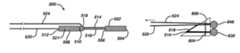
- FIG. 1 a through FIG. 1 dillustrate an embodiment of a suture-anchoring device and its deployment according to the present invention.
- FIG. 2 a through FIG. 2 dillustrate a nonsliding embodiment of a suture fixation device according to the present invention comprising a twisted braid suture head.
- FIG. 3 a through FIG. 3 cillustrate nonsliding embodiments of suture fixation devices according to the present invention comprising crocheted suture heads.
- FIG. 4 a through FIG. 4 dillustrate sliding embodiments of suture anchoring devices according to the present invention.
- FIG. 5 a through FIG. 5 dillustrate embodiments of suture anchoring devices according to the present invention comprising interpenetrating suture.
- FIG. 6 a and FIG. 6 billustrate an embodiment of a suture anchoring device applicable to repairing a meniscus in a knee according to the present invention.
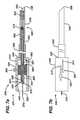
- FIG. 7 a and FIG. 7 billustrate an embodiment of a delivery tool of the present invention that can be used to deliver the anchoring device illustrated in FIG. 6 a and FIG. 6 b to tissue.
- FIG. 8 a and FIG. 8 billustrate an embodiment of a delivery tool of the present invention including a curved delivery needle.
- FIG. 9 a through FIG. 9 killustrate an embodiment of a surgical repair procedure of the present invention, for repairing a torn meniscus in a knee.
- FIG. 10 a and FIG. 10 billustrate an embodiment of a delivery tool of the present invention for single-location anchoring and for daisy-chaining anchoring locations.
- FIG. 11 a through FIG. 11 iillustrate an embodiment of a daisy-chaining anchoring procedure of the present invention.
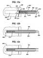
- FIG. 12 a through FIG. 12 eillustrate an embodiment of delivery of suture anchoring devices of the present invention into hard tissue.
- FIG. 13illustrates an embodiment of a sub-cortically dilated hole in a bone for receiving a suture anchoring device of the present invention.
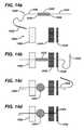
- FIG. 14 a through FIG. 14 dillustrate an alternative embodiment of a delivery device of the present invention.
- FIG. 15 a through FIG. 15 dillustrate an embodiment of a suture anchoring system of the present invention wherein a suture head is used in conjunction with an intermediate anchoring implant.
- FIG. 16 a through FIG. 16 dillustrate another embodiment of an anchoring system of the present invention wherein a suture head is deployed internally to an intermediate anchoring implant.
- the present inventiongenerally provides devices, systems and methods for anchoring suture to tissue.
- tissueis used herein to refer to any natural body tissue including, but not limited to cartilage, skin, muscle, bone, tendon, ligament and organs, as well as to prosthetic materials such as grafts or other prosthetics that can be repaired or attached to natural body tissues with sutures and anchoring devices.
- suture anchoring devicesfabricated substantially from surgical suture or any elongated, thread-like materials that can be used as medical devices (hereinafter, “suture”) are disclosed herein.
- the suturecan comprise a single filament or a plurality of interwoven filaments, and can have any cross-sectional shape including, but not limited to a substantially circular cross section, and a flattened ribbon or tape-like cross section. Further, the suture can be non-absorbable, bioabsorbable, or partially bioabsorbable. Without deviating from the intent or scope of the invention, the suture material can be mechanically or chemically modified, treated or coated to enhance lubricity or knot-holding ability, to elute a medicament, or for any combination of the aforementioned or other therapeutic purposes. Further, although various embodiments of anchoring devices in accordance with the invention can be constructed entirely of suture, additional components such as clips or adhesives can be included without deviating from the intent or scope of the invention.
- An anchoring devicegenerally comprises one or more segment of suture (hereinafter, suture tail) extending from an anchoring member having a longitudinally elongated, small cross section initial configuration (hereinafter, a suture head).
- suture tailan anchoring member having a longitudinally elongated, small cross section initial configuration
- the suture headUpon deployment, the suture head is reconfigured (collapsed) to a longitudinally compressed configuration (an anchoring knot) of correspondingly larger cross-section than the suture head. That is, the anchoring knot has a larger cross sectional area and a larger average cross sectional dimension (hereinafter, cross-sectional dimension) than the corresponding dimensions of the suture head.
- the suture anchoring devicefor delivery to tissue, is disposed in a cannulated delivery needle having an outer diameter substantially smaller than the cross-sectional dimension of the anchoring knot.
- collapsing a suture head to an anchoring knotis accomplished by tensioning a specific one or more (collapse tail) of the one or more suture tail, with respect to the suture head.
- FIG. 1 aschematically illustrates an embodiment of a suture-anchoring device 100 according to the present invention.
- the suture anchoring device 100illustrated undeployed in FIG. 1 a , comprises a suture head 102 having a first head end 104 , a second head end 106 , a head length 108 therebetween and an undeployed cross-sectional dimension 110 that is smaller than the head length 108 .
- a first suture tail 112is seen to extend substantially from the first head end 104 .
- a second suture tail 114extends substantially from the second head end 106 .
- the second suture tail 114comprises a closed loop of suture extending from the second head end 106 .
- two or more suture tailsextend from one or both of the first 104 and the second head end 106 .
- the suture head 102comprises a longitudinally extended, preformed knot configuration, by which we mean any braided, crocheted, woven, knotted or otherwise configured section of suture that, for deployment and fixation with respect to tissue, can be readily collapsed into a longitudinally compressed, expanded cross-section form referred to herein as an anchoring knot.
- the suture head 102is seen to be disposed in a cannulated delivery needle 116 for delivery into or through tissue 118 .
- the delivery needle 116has a distal delivery end 120 , an outer diameter 122 and an inner diameter 124 . Further, the delivery needle 116 can be straight or curved along its length. In an embodiment, the delivery end 120 includes a tissue-penetrating point 126 . In another embodiment (not illustrated), the delivery end 120 is not pointed.
- a piston 128 having a longitudinal piston cannulation 130 therethroughis seen to be slidingly disposed within the delivery needle 116 , proximal to the suture head 102 .
- the first suture tail 112is seen to pass proximally from the suture head 102 through the piston cannulation 130 .
- the suture head 102is delivered from the delivery needle 116 to the tissue 118 by pushing the piston 128 distally against the suture head 102 to expel the suture head 102 from the delivery needle 116 .
- the piston 128is seen to abut the expelled suture head 102 .
- the piston 128is coupled to a proximal handle (not illustrated) that provides control of the longitudinal position of the piston 128 within the delivery needle 116 .
- the suture head 102is delivered from the delivery needle 116 by distally pulling the second suture tail 114 .
- the needle 116is straight.
- the needle 116is curved and the piston 128 is flexible so as to enable the piston 128 to slide along the curve for delivery of the suture head 102 from the needle 116 .
- the suture head 102substantially comprises suture, it is also flexible for sliding through a curved needle.
- the suture head 102is collapsed to form an anchoring knot 136 .
- the suture head 102is collapsed to the anchoring knot 136 by tensioning 138 the first suture tail 112 (a collapse tail) with respect to the suture head 102 after the suture head 102 has been pushed entirely out of the distal end 120 of the needle 116 by the piston 128 .
- the piston 128abutting the suture head 102 provides a counter force to the tensioning 138 of the first suture tail 112 with respect to the suture head 102 , to collapse the suture head 102 to the anchoring knot 136 .
- the term “collapse tail”is used herein to describe any suture tail that, when tensioned with respect to a suture head, can be used to collapse the suture head to an anchoring knot.
- the anchoring knot 136has a knot length 140 that is shorter than the head length 108 , and a correspondingly increased cross section 142 , determined substantially by the volume of suture originally comprising the suture head 102 .
- the first suture tail 112is tensioned concurrently with the suture head 102 being expelled from the distal end 120 of the needle 116 , collapsing the suture head 102 to the anchoring knot 136 as it emerges from the needle 116 .
- the suture head 102does not extend distally from the delivery needle 116 the full head length 108 during deployment, but instead extends only the knot length 140 . This shallower extension can provide deployment of the anchoring device 100 that minimizes surgical trauma to tissue positioned distally beyond, but in proximity to the distal end of the delivery needle.
- FIG. 1 dillustrates a fully deployed anchoring device 144 , wherein the needle 116 is seen to have been removed, and the anchoring knot 136 is anchored with respect to the tissue 118 , leaving the first suture tail 112 available for connection to tissue or to another anchoring device, or for any other surgical step requiring a suture that is anchored to tissue.
- the anchoring knot 136can be deployed behind a tissue wall as illustrated in FIG. 1 d , or within bulk tissue, for example, within a bone for anchoring suture to the bone.
- two or more suture heads, interconnected by sutureare disposed in a needle for surgical procedures requiring two or more tissue anchoring points.
- the anchoring knot 136has a knot length 140 that is less than the head length 108 , and a deployed cross sectional dimension 142 that is correspondingly greater than the undeployed cross sectional dimension 110 , and greater than the outer diameter 122 of the needle 116 .
- the anchoring knot 136is amorphous, that is, having an incompletely predetermined external shape following collapse from the suture head 102 to the anchoring knot 136 .
- anchoring knots formed from suture heads according to the various embodiments of the present inventionare amorphous. Although neither the suture head 102 nor the anchoring knot 136 have a completely predetermined shape, either can be reasonably described as having a length and a diameter transverse to the length, the diameter approximately defined by the average cross-sectional dimension transverse to the length.
- the head length 108is between approximately ten and fifty times the undeployed cross-sectional dimension 110
- the deployed cross-sectional dimension 142is between three and ten times the undeployed cross-sectional dimension 110 .
- the suture-anchoring device 100can be fabricated substantially from a single continuous length of suture, or from a plurality of coupled lengths of suture.
- the plurality of coupled lengthscan include a single type of suture or a combination of suture types and sizes.
- the one or more suture tailcan be fixedly coupled to the anchoring knot, or slidably coupled therethrough.
- the inner diameter 124 of the needle 116is less than about six times a diameter of the suture material from which the suture head is configured. In another embodiment, the inner diameter 124 of the needle 116 is less than about four times a diameter of the suture material from which the suture head is configured.
- the design of the suture headsubstantially determines the overall design and procedural details of delivery and deployment.
- the design of the suture headalso determines the pull-out strength of the deployed anchoring knot, and the anchor density, that is, the mass of suture material in an anchoring knot having a given cross-sectional dimension.
- Many anchoring device designsare possible within the scope of the present invention. For nonlimiting descriptive purposes herein, these designs are grouped into two general categories respectively called non-sliding embodiments, wherein all suture tails extending from a fully deployed anchoring knot are fixed thereto substantially without sliding through the knot, and sliding embodiments, wherein at least one length of suture slidingly passes through the fully deployed anchoring knot. Sliding embodiments are advantageous for some surgical applications, for example, where it is desirable to tension suture between a deployed anchoring member and attached tissue, to draw two or more anchoring devices together to close a tissue tear, or to gather together intervening tissue between anchoring devices.
- the anchoring devicecomprises at least a first length of suture and a second length of suture.
- the first length of suturegenerally comprises the bulk of a suture head (and, following deployment, a corresponding anchoring knot).
- the second length of suturecomprises two suture tails and is slidable through the anchoring knot by tensioning one or the other of the two tails individually with respect to the anchoring knot.
- the sliding embodimentcan further include additional sliding sutures having corresponding pairs of suture tails.
- Sliding embodimentscan also include one or more fixed suture tail that can comprise a portion of the first length of suture, or an additional length of suture fixedly connected, for example, tied, to the first length of suture. Further, depending on the specific design of the suture head, one or more suture tail can comprise one or both of a collapse tail and a sliding tail.
- Nonsliding embodimentscan comprise a single length of suture or a plurality of suture lengths that are fixedly joined together, for example, by one or more knot.
- Nonsliding embodimentsinclude a suture head from which one or more suture tail extends, at least one of the one or more suture tail comprising a collapse tail.
- a suture head according to the present inventioncan comprise any preformed knot configuration that can be collapsed from a longitudinally extended form to a longitudinally compressed, increased cross section anchoring knot.
- the suture headincludes a plurality of openings comprising loops, penetrations or other openings formed along a first longitudinal section of suture.
- a second longitudinal section of suture comprising a collapse tailis woven through two or more of the plurality of the openings.
- One or more suture tailsextends from the suture head, at least one of the one or more suture tails comprising the collapse tail.
- the first section of suture, the second section of suture and the one or more suture tailcomprise a single continuous length of suture.
- the first section of suture, the second section of suture and the one or more suture tailcomprise two or more joined lengths of suture.
- Anchoring devices of the present inventioncan include one or more of a variety of types of suture heads, and can be fabricated using a variety of methods.
- One type of suture headcomprises a braided section of suture that is collapsible to an anchoring knot. Any type of suture braiding can be used to configure the suture head.
- An embodiment of a nonsliding, twisted braid suture-anchoring deviceis schematically illustrated in FIG. 2 a and FIG. 2 b .
- FIG. 2 aillustrates a first configuration step 200 , wherein a length of suture 202 is seen to have been formed into a starting loop 204 having a first head end 206 , a second head end 208 and a head length 210 therebetween.
- a suture tail 212extends from the second head end 208 .
- FIG. 2 billustrates a configured suture head 214 .
- the loop 204has been repetitively twisted to provide a plurality of openings 216 along the head length 210 .
- the suture tail 212is seen to have been woven through the plurality of openings 216 from the second head end 208 to the first head end 206 , and extends from the first head end 206 , where it comprises a collapse tail.
- FIG. 2 bthe suture heads are generally illustrated in an expanded schematic form to support description of routing of suture therethrough.
- Any suture head disclosed hereincan be readily compressed in cross section, for example, for disposition within a cannulated delivery needle, as illustrated in FIG. 1 a .
- FIG. 2 cillustrates the suture head 214 in a compressed cross section form 218 , as for disposition in a delivery needle.
- the suture head 214can be collapsed to an anchoring knot 220 , as illustrated in FIG. 2 d , by tensioning the suture tail 212 (collapse tail) with respect to the suture head 214 .
- tensioning the first suture tail 212 with respect to the suture head 214we mean tensioning (pulling) the first suture tail 212 away from the suture head 214 , so that the portion of the first suture tail 212 that is woven through the plurality of openings 216 is pulled further through the plurality of openings 216 and through the first head end 206 , thereby gathering or bunching the twisted suture along the head length 210 into the anchoring knot 220 .
- tensioning 222 the first suture tail 212 with respect to the suture head 214an abutment to the first head end, for example, the piston 128 of FIG. 1 is required to hold the suture head in position for collapsing to the anchoring knot 220 .
- friction with the tissuecan also retain the suture head during collapse to an anchoring knot.
- any type and diameter of suture, and any number of openings 216 for braiding or otherwise passing suture therethrough,can be used to configure a suture head according to the present invention.
- a larger number of openingsgenerally provides a longer suture head and, upon deployment, an anchoring knot having a larger cross sectional dimension, thereby providing greater fixation strength of the anchoring knot with respect to tissue.
- a 20 mm long suture headcomprises between fifteen and thirty-five openings through which suture can be woven.
- the plurality of openingsis between twenty and thirty openings.
- the suture headis approximately 25 millimeters (mm) in length, and upon deployment in tissue, the suture head collapses to a substantially amorphous anchoring knot approximately five mm in diameter.
- a suture head approximately 20 mm longwas configured from partially absorbable, polyethylene-containing braided suture approximately 0.5 millimeters (mm) in diameter (ORTHOCORDTM Orthopaedic Suture from DePuy Mitek, Raynham, Mass.).
- mmmillimeters
- ORTHOCORDTM Orthopaedic Suturefrom DePuy Mitek, Raynham, Mass.
- Deployment of a similarly configured anchoring device through a 2-mm diameter hole in artificial bone having a 3-mm thick, 35-durometer cortexprovided a pullout strength of approximately 22 pounds.
- Braidsfor example, can be formed by a variety of methods and with any number of suture sections braided together, and a suture head configured to include any braiding pattern is within the scope of the present invention. Further, braiding comprises only one of a variety of methods for configuring a suture head according to the present invention. Other methods for configuring a suture head can be adapted, for example, from other textile arts such as crocheting and weaving.
- Another anchoring device of the present inventionincludes a suture head configured using a chain of suture loops.
- the chain of loopscan comprise a plurality of independent suture loops, a physically connected chain of discrete loops, or a plurality of loops formed along a continuous length of suture using known textile arts such as crocheting, where each of the plurality of loops in a chain is formed by pulling a section of the suture through a previously formed loop in the suture.
- the plurality of loopsprovides a corresponding plurality of openings through which suture can be woven.
- Nonsliding embodiments of suture anchoring devicescomprising suture heads configured using crocheted suture are schematically illustrated in FIG. 3 a through FIG. 3 c .
- FIG. 3 aillustrates a crochet configuration step 230 wherein a length of suture 232 has been crocheted to define a plurality of openings 234 along a crocheted section 236 having a first crocheted end 238 and a second crocheted end 240 .
- a first suture tail 242extends from the first crocheted end 238 and a second suture tail 244 extends from the second crocheted end 240 .
- FIG. 3 billustrates a first embodiment 250 of a crocheted suture-anchoring device. It comprises a suture head 252 wherein the first suture tail 242 is seen to weave through one or more of the plurality of openings 234 along the crocheted section 236 from the first crocheted end 238 to the second crocheted end 240 , and extends from the second crocheted end 240 .
- the suture head 250can be collapsed to an anchoring knot by tensioning the first suture tail 242 (collapse tail) with respect to the suture head 252 .
- FIG. 3 cillustrates a second embodiment 260 of a crocheted suture-anchoring device.
- the second embodiment 260resembles the first embodiment 250 , with the addition that in the second embodiment 260 , after being woven from the first 238 to the second crocheted end 240 , the first suture tail 242 is returned through one or more of the plurality of openings 234 from the second crocheted end 240 to the first crocheted end 238 , to extend from the first crocheted end 238 .
- the suture head 262can be collapsed to an anchoring knot by tensioning the first suture tail 242 (collapse tail) with respect to the suture head 262 .
- the second suture tail 244is directly connected to and extends from the second crocheted end, and tensioning the second suture tail 244 with respect to the respective suture head 252 , 262 (providing an abutment against second crocheted end 240 does not collapse the respective suture head to an anchoring knot.
- the second suture tail 244can be used, for example, to pull the respective suture head 252 , 262 , into a cannulated needle, for delivery to tissue or through tissue, without collapsing the respective suture head to an anchoring knot.
- FIG. 4 a through FIG. 4 dillustrate sliding embodiments of suture anchoring devices according to the present invention.
- FIG. 4 aillustrates a sliding embodiment of a twisted ring suture-anchoring device 300 .
- the twisted ring suture-anchoring device 300comprises a suture ring 302 that is a closed ring of suture repetitively twisted to form a plurality of openings 304 between a first twist end 306 and a second twist end 308 .
- a length of suture 310 having a first suture tail 312 and a second suture tail 314is woven through the plurality of openings 304 between the first twist end 306 and the second twist end 308 , and returning through at least one of the plurality of openings 304 near the first twist end 306 , to configure a suture head 316 having both the first 312 and the second suture tail 314 extending from the first twist end 306 .
- the suture head 316can be collapsed to an anchoring knot by simultaneous tensioning of the first 312 and the second suture tail 314 with respect to the suture head 316 .
- the first 312 and the second suture tail 314comprise collapse tails when tensioned simultaneously with respect to the suture head 316 .
- the length of suture 310is not fixedly connected to the suture ring 302 , but woven therethrough to preserve slidability of the length of suture 310 through the anchoring knot.
- the length of suture 310can slide through the anchoring knot by individually tensioning either the first 312 or the second suture tail 314 respectively, with respect to the anchoring knot.
- a suture ring used to configure a suture head according to the present inventioncan comprise suture formed as a continuous ring of suture material, or a length of suture closed to form the ring. Any method of closing the length of suture to a ring can be used, including but not limited to knotting, welding, gluing, or crimping with or without a binding clamp or other joining member.
- the suture ringcan include a plurality of substantially parallel strands of suture about its circumference, braided, crocheted, or otherwise interlocked suture.
- the suture ringcomprises a continuous ring of suture having a first circumference, that is doubled over to form a doubled suture ring having a second circumference that is substantially half the first circumference.
- FIG. 4 billustrates a sliding embodiment of a suture-chain suture-anchoring device 322 .
- the suture-chain suture-anchoring device 322comprises a connected chain of suture rings 324 defining a plurality of openings 326 between a first chain end 328 and a second chain end 330 .
- a length of suture 332 having a first suture tail 334 and a second suture tail 336is woven through the plurality of openings 326 between the first chain end 328 and the second chain end 330 , then returning through at least one of the plurality of openings 326 near the first chain end 328 , to configure a suture head 338 having both the first 334 and the second suture tail 336 extending from the first chain end 328 .
- the suture head 338can be collapsed to an anchoring knot by simultaneous tensioning of the first 334 and the second suture tail 336 with respect to the suture head 338 .
- the first 334 and the second suture tail 336comprise collapse tails when tensioned simultaneously. As can be seen in FIG.
- the length of suture 332is not fixedly connected to the chain of suture rings 324 , but woven therethrough to preserve slidability of the length of suture 332 through the anchoring knot.
- the length of suture 332can slide through the anchoring knot by individually tensioning either the first 334 or the second suture tail 336 respectively, with respect to the anchoring knot.
- FIG. 4 cillustrates a sliding embodiment of a wound-ring suture-anchoring device 344 providing a sliding connection between suture and a deployed anchoring knot.
- the wound-ring suture-anchoring device 344comprises a suture ring 346 that can be any type of suture ring described hereinabove.
- the wound-ring suture-anchoring device 344also comprises a first length of suture 348 having a first suture tail 350 and a second suture tail 352 .
- the first length of suture 348is wound substantially helically about the suture ring 346 to configure a suture head 354 , with the first 350 and the second suture tail 352 extending from the suture ring 346 substantially adjacent to one another about the circumference of the suture ring 346 .
- the first length of suture 348is wound substantially helically about a second length of suture.
- the second length of suture, with the winding about it,is subsequently joined at a closure point 356 along its length to form the suture ring 346 .
- the suture head 354can be collapsed to an anchoring knot by simultaneous tensioning of the first 350 and the second suture tail 352 with respect to the suture head 354 .
- the first 350 and the second suture tail 352comprise collapse tails when tensioned simultaneously.
- the first length of suture 348can slide through the anchoring knot by individually tensioning either the first 350 or the second suture tail 352 respectively, with respect to the anchoring knot.
- FIG. 4 dA sliding embodiment of a crochet-type suture-anchoring device 362 is illustrated in FIG. 4 d .
- the crochet-type suture-anchoring device 362comprises a crocheted section of suture 364 defining a plurality of openings 366 between a first crocheted end 368 and a second crocheted end 370 .
- the crocheted section 364is similar to the crocheted section 236 described in association with FIG. 3 a .
- the crochet-type suture-anchoring device 362also comprises a first length of suture 372 having a first suture tail 374 and a second suture tail 376 .
- the first length of suture 372is woven through one or more of the plurality of openings 366 between the first crocheted end 368 and the second crocheted end 370 , and returned to the first crocheted end 368 through at least one of the plurality of openings 366 near the first crocheted end 368 .
- the first 374 and the second suture tail 376extend from the first crocheted end 368 .
- the fraction of the plurality of openingscomprises approximately every third opening of the plurality of openings 366 .
- the first length of suture 372is woven through substantially each of the plurality of openings 366 .
- the intervalvaries along the plurality of openings 366 between the first crocheted end 368 and the second crocheted end 370 .
- the first length of suture 372passes through a single one of the plurality of openings 366 , the single one of the plurality of openings 366 functioning as an eyelet through which the first length of suture 372 passes.
- any number of additional lengths of suturecan be independently woven through one or more of the plurality of openings, thereby providing an anchoring device having a plurality of suture legs extending therefrom (a multisuture anchoring device).
- two, three or four lengths of sutureare each woven through one or more of the plurality of openings, providing anchoring devices respectively comprising four, six, or eight legs of suture extending therefrom.
- one or more suture needle with attached suturecan be passed through a deployed anchoring knot to provide a multisuture anchoring device.
- the suture head 378can be collapsed to an anchoring knot by simultaneous tensioning of the first 374 and the second suture tail 376 with respect to the suture head 378 .
- the first 374 and the second suture tail 376comprise collapse tails when tensioned simultaneously with respect to the suture head 378 .
- the first length of suture 372can slide through the anchoring knot by individually tensioning of either the first 374 or the second suture tail 376 respectively, with respect to the anchoring knot.
- FIG. 5 a through FIG. 5 dillustrate embodiments of suture anchoring devices comprising interpenetrating suture.
- a suture headaccording to these embodiments comprises a plurality of longitudinally distributed, substantially transverse penetrations through the material of a first section of suture, and a second section of suture woven through the plurality of penetrations.
- the plurality of penetrationscan comprise any type of penetrations.
- the plurality of penetrationsis defined using a sharp instrument such as a sewing or suturing needle connected to a suture tail.
- the plurality of penetrationscomprises a plurality of slits or bores is formed through the suture material to enable weaving of a suture tail therethrough.
- a plurality of preformed penetrationsis provided during fabrication of the section of suture.
- the sutureitself comprises a braided material, for example, a braided suture, and the plurality of penetrations pass through the braid at a corresponding plurality of locations.
- FIG. 5 a and FIG. 5 billustrate interpenetrating sliding embodiments.
- FIG. 5 aillustrates a first interpenetrating sliding embodiment 400 of a suture anchoring device wherein a suture head 402 comprises a suture ring 404 having a plurality of penetrations 406 distributed around its circumference.
- the suture ring 404can be any type of suture ring disclosed herein.
- the suture head 402further comprises a first length of suture 408 woven through the plurality of penetrations 406 , and terminating in a first suture tail 410 and a second suture tail 412 , each extending from the suture head 402 substantially adjacent to one another about the circumference of the suture ring 404 .
- the suture head 402can be collapsed to an anchoring knot through which the first length of suture 408 can slide after the anchoring knot is formed, by simultaneously tensioning the first 410 and the second suture tail 412 with respect to the suture head 402 .
- the first 410 and the second suture tail 412comprise collapse tails when tensioned simultaneously.
- the first length of suture 408can slide through the anchoring knot by individually tensioning either the first 410 or the second suture tail 412 respectively, with respect to the anchoring knot.
- the suture ring 404comprises a second length of suture that is open at a point 418 on the circumference, and the ring shape is maintained by the adjacent penetrations 420 , 422 of the second length of suture by the first length of suture 408 .
- the second length of suturepenetrates the first length of suture, instead of the first length of suture 408 penetrating the second length of suture.
- FIG. 5 billustrates a second interpenetrating sliding embodiment 424 of a suture anchoring device
- a suture head 426comprises a first length of suture 428 having a plurality of penetrations 430 along a first portion 432 of its length, through which a second portion 434 of the length passes to define a corresponding plurality of openings 436 .
- the suture head 426further comprises a second length of suture 438 woven through the plurality of openings 436 , and terminating in a first suture tail 440 and a second suture tail 442 , each extending from the suture head 426 .
- the suture head 426can be collapsed to an anchoring knot through which the second length of suture 438 can slide, by simultaneously tensioning the first 440 and the second suture tail 442 with respect to the suture head 426 .
- the first 440 and the second suture tail 442comprise collapse tails when tensioned simultaneously.
- the second length of suture 438can slide through the anchoring knot by individually tensioning either the first 440 or the second suture tail 442 respectively, with respect to the anchoring knot.
- FIG. 5 c and FIG. 5 dillustrate interpenetrating suture nonsliding embodiments of suture anchoring devices.
- FIG. 5 cillustrates a first interpenetrating nonsliding embodiment 448 wherein a suture head 450 having a first head end 452 and a second head end 454 comprises a first length of suture 456 having a plurality of penetrations 458 along a first portion 460 of its length between the first head end 452 and the second head end 454 .
- a second portion 462 of the lengthpasses through the plurality of penetrations 458 and extends from the first head end 452 as a suture tail 464 .
- the suture head 450can be collapsed to an anchoring knot by tensioning the suture tail 464 with respect to the suture head 450 .
- one of the penetrations 468 of the second portion 462 through the first portion 454is reinforced by knotting or by another means to prevent the suture head from unraveling during deployment.
- the plurality of penetrations 458is seen to define a plurality of openings 470 along the suture head 450 between the first head end 454 and the second head end 456 .
- FIG. 5 dillustrates a second interpenetrating nonsliding embodiment 472 .
- the second nonsliding embodiment 472comprises a suture head 474 that resembles the suture head 450 of FIG. 5 c , with the addition that in the second embodiment 472 , the suture tail 464 is seen to be reversed in direction and additionally woven through one or more of the plurality of openings 470 , to extend from the second head end 454 .
- This additional pass of the suture tail 464provides a larger volume of suture material in the suture head 474 of the second embodiment 472 , compared with the volume of suture material in the suture head 450 of the first embodiment 448 .
- a larger volume of suture in a suture headprovides a correspondingly larger anchoring knot upon deployment in tissue.
- the suture head 474can be collapsed to an anchoring knot by tensioning the suture tail 464 with respect to the suture head 474 .
- various nonsliding embodimentscan be converted to sliding embodiments by passing an additional length of suture through an opening in a nonsliding suture head before deployment.
- the second suture tail 114comprises a closed loop of suture
- passing a length of suture through the loop before delivering the anchoring device 100 to tissueprovides a sliding embodiment of the suture anchoring device, as the passed length of suture will be slidable with respect to the anchoring knot 136 .
- various sliding embodimentscan be converted to nonsliding embodiments, for example, by tying a knot in one or more sliding suture tail.
- suture anchoring devicesdisclosed herein are within the scope of the present invention, including but not limited to variations in suture material, size, number and combinations of suture lengths used to construct the anchoring device, the number of openings through which suture comprising a collapse tail passes along a suture head, and the number of sliding and nonsliding suture tails extending from a suture head. Further, any number of suture anchoring devices can be coupled together by suture to provide multi-point anchoring systems.
- FIG. 6 aillustrates an embodiment of a dual anchoring device 500 according to the present invention that in one embodiment is used for repairing torn meniscal tissue.
- the dual anchoring device 500comprises a first suture head 502 having a first distal end 504 and a first proximal end 506 , and a second suture head 508 having a second distal end 510 and a second proximal end 512 .
- the second suture head 508is seen to be positioned proximal to the first suture head 502 .
- the first suture head 502is a sliding suture head that can be any type of sliding suture head disclosed herein, or another sliding suture head.
- the first suture head 502is a crochet-type sliding suture head similar to the suture head 378 described in association with FIG. 4 d .
- the first suture head 502comprises two distal collapse tails 514 , 516 that are seen to extend form the first proximal end 506 toward the second suture head 508 .
- the two distal collapse tails 514 , 516comprise a continuous length of suture that passes through the first suture head 502 .
- the two distal collapse tails 514 , 516comprise a suture bridge between the first 502 and the second suture head 508 .
- the second suture head 508is a non-sliding suture head that can comprise any type of nonsliding suture head disclosed herein, or another nonsliding suture head.
- the second suture head 508resembles the crochet-type nonsliding suture head 252 described in association with FIG. 2 c , with the addition of an integrated sliding knot 518 extending from the second distal end 510 .
- the second suture head 508also comprises a proximal collapse tail 520 extending proximally from the second proximal end 512 .
- the second suture head 508 , the sliding knot 518 , and the two distal collapse tails 514 , 516comprise a single continuous length of suture.
- the sliding knot 518rather than extending from the second distal end 510 , is disposed at a location 521 between second distal end 510 and a second proximal end 512 along the second suture head 508 .
- a partially expanded view 522 of the dual anchoring device 500is shown schematically in FIG. 6 b , illustrating the configuration of an embodiment of the sliding knot 518 .
- a first one 514 of the two distal collapse tails 514 , 516is seen to substantially comprise one portion of the sliding knot 518 , and to connect to (or be continuous with) the second suture head 508 at the second distal end 510 .
- the second distal collapse tail 516is seen to pass through the sliding knot to extend proximally from the sliding knot 518 , continuous with a tensioning tail 524 .
- the second collapse tail 516is also seen to pass through a suture loop 526 integral with the second suture head 508 and extending distally therefrom.
- FIG. 7 aAn embodiment of a dual suture head delivery tool 530 for delivering the dual anchoring device 500 to tissue is schematically illustrated in FIG. 7 a in a cross-sectional view 532 and in FIG. 7 b in an external view 534 .
- the dual head delivery tool 530is seen to comprise a cannulated delivery needle 536 having a distal needle end 538 , a proximal needle end 540 and a longitudinal needle cannulation 542 therebetween.
- the delivery needle 536is proximally coupled to a cannulated handle 544 having a handle wall 546 and a substantially cylindrical handle cannulation 548 , the needle cannulation 542 being continuous with the handle cannulation 548 .
- the needle 536is proximally reinforced by a stiffening member 550 .
- each of the needle 536 and the piston 552is straight.
- the needle 536comprises one or more curve between the distal needle end 538 and the proximal needle end 540 , and the piston is flexible enough to be pushed and pulled slidingly through the needle cannulation 542 .
- the piston 552comprises a flexible tube.
- the piston 552comprises a flexible, substantially helical coil.
- a piston positioning member 558is fixedly connected to the piston 552 , and slidably disposed within the handle cannulation 548 .
- the positioning member 558is an annular member disposed about the piston 552 .
- the piston positioning member 558substantially irreversibly locks in position longitudinally when maximally advanced distally within the handle cannulation 548 . Any means of locking the piston positioning member 558 can be used.
- the piston positioning member 558 and the handle 544comprise interlocking latching members 560 , 562 to lock the piston positioning member 558 distally within the handle 544 .
- a control member 564is connected to the positioning member 558 , for positioning the piston 552 longitudinally within the dual head delivery tool 530 , from outside the delivery device.
- the control memberis shown rotated ninety degrees about a longitudinal axis of the tool 530 in FIG. 7 a with respect to FIG. 7 b .
- the control member 564extends laterally outward from the positioning member 558 , through a slotted opening 566 in the handle wall 546 .
- the slotted opening 566can have any configuration that accommodates the requirements an anchoring device disposed in the delivery device, and corresponding surgical delivery requirements. In one embodiment, as illustrated in FIG. 7 a and FIG.
- the slotted opening 566is substantially H-shaped.
- the H-shaped openingincludes first and second longitudinal slots 812 , 814 having respective longitudinal positions that differ from one another along the handle wall 546 , each of the two slots being adapted by its respective position for delivery of one of the first 502 and the second suture head 508 from the delivery needle 536 .
- the slotted openingis substantially T-shaped, L-shaped, longitudinally linear, or has another configuration, respective configurations being adapted to accommodate various suture head delivery requirements
- the slotted openingcomprises means for locking the piston positioning member 558 distally in the handle cannulation 548 .
- the control member 564can comprise any means for communicating one or both of longitudinal and circumferential positioning force to the positioning member 558 and thereby to the piston 552 .
- the control member 564is a shaft fixedly connected to the positioning member 558 through the slotted opening 566 .
- the control member 564includes means to releasable prevent the piston from moving within the dual head delivery tool 530 .
- the control member 564is a thumbscrew that is threaded into the positioning member 558 through the slotted opening 566 , such that rotation of the thumbscrew can be used to selectively lock and unlock the position of the piston within the dual head delivery tool 530 .
- the control member 564is resiliently loaded with respect to the handle wall 546 to provide a predetermined resistance to movement of the control member 564 along the slotted opening 566 .
- the dual anchoring device 500is seen to be disposed within the dual head delivery tool 530 , substantially within the needle cannulation 542 , distal to the piston distal end 554 .
- the second collapse tail 520 and the tensioning tail 524pass proximally from the dual anchoring device 500 through the piston cannulation 557 .
- Proximal to the piston proximal end 556the tensioning tail 524 terminates at a tensioning tail end 568 and the second collapse tail 520 terminates at a second collapse tail end 570 .
- the second collapse tail 520also comprises a releasable holding member 572 disposed proximally to the proximal piston end 556 , outside the piston cannulation 557 .
- the releasable holding member 572prevents the second collapse tail 520 from sliding distally through the cannulation of the piston 552 .
- the releasable holding member 572is a releasable clamp attached to the second collapse tail 520 .
- the releasable holding member 572is a releasable knot in the second collapse tail 520 .
- proximally tensioning the second collapse tail 520releases the releasable knot.
- the second collapse tail 520can slide distally through the cannulation of the piston 552 .
- the control member 564controls the longitudinal position of the distal end of the piston 552 within the delivery needle 536 , and thereby controls the expulsion of the dual anchoring device 500 from the delivery needle 536 .
- the control member 564can be used to selectively expel only the first suture head 502 from the delivery needle 536 for a predetermined surgical step, and selectively expel the second suture head 508 for a later surgical step, thus enabling multipoint anchoring procedures using devices and methods of the present invention.
- FIG. 8 aAn embodiment of a curved needle delivery tool 574 is illustrated in FIG. 8 a .
- the curved needle delivery tool 574generally resembles the dual head delivery tool 530 associated with FIG. 7 a and FIG. 7 b , which comprises a straight delivery needle.
- the curved needle embodiment 574includes a cannulated curved delivery needle 576 having a distal delivery end 578 and a proximal end 580 that is rotatably coupled to a handle 584 about a common longitudinal axis 586 .
- a control member 588is accessible on an outside surface 590 of the handle 584 .
- the curved delivery needle 576further comprises one or more curved portion 592 , distal of which the curved needle 576 deviates from the axis 586 .
- the curved needle delivery tool 574comprises a plurality of preferred relative rotational orientations about the axis 586 between the handle 584 and the curved needle 576 .
- the plurality of preferred orientationscomprises a plurality of detents 594 circumferentially distributed about the circumference of one or both of the handle 590 and the curved needle 576 .
- angular markingsare provided on one or both of the handle 584 and the curved needle 576 to indicate the relative rotational orientation between the curved needle 576 and the handle 584 .
- FIG. 8 aillustrates the curved needle delivery tool 574 in a first angular orientation 596 between the handle 584 and the curved needle 576 .
- FIG. 8 billustrates the curved needle delivery tool 574 in a second angular orientation 598 between the handle 584 and the curved needle 576 .
- FIG. 9 a through FIG. 9 kschematically illustrate a surgical repair procedure for a torn meniscus in a knee using the dual anchoring device 500 illustrated in FIG. 6 and the dual head delivery tool 530 illustrated in FIG. 7 .
- the procedurecan be performed arthroscopically or as an open surgical procedure.
- the patientis prepared according to known preparatory and surgical techniques including the provision of access to the torn meniscus.
- the following description of the procedurereferences FIG. 6 and FIG. 7 as well as FIG. 9 a through FIG. 9 n .
- FIG. 9 a through FIG. 9 nincludes an illustration of a surgical step, in some of the figures accompanied by an illustration representing a position of the control member 564 in the substantially H-shaped slotted opening 566 as illustrated in FIG. 7 .
- FIG. 9 aillustrates a first step in which the delivery needle 536 of the dual head delivery tool 530 is seen to have been passed through a meniscus 802 that has suffered a meniscal tear 804 .
- the meniscus 802is seen to have a first meniscal surface 806 which faces toward a femur (not shown) and a second meniscal surface 808 which faces laterally or medially away from the femur. It is preferred to minimize the protrusions on the first surface 806 facing the femur to minimize irritation etc. of such surface which bears a load from the femur.
- the delivery needle 536is seen to have penetrated the meniscus 802 at a first location 810 , entering through the first meniscal surface 806 , and exiting through the second meniscal surface 808 .
- the first location 810is determined by the surgeon performing the procedure, to optimize closure of the meniscal tear 804 .
- the delivery needle 536penetrates through the meniscus 802 across the meniscal tear 804 .
- the H-shaped slotted opening 566is seen to comprise a first longitudinal channel 812 and a second longitudinal channel 814 , each having a respective proximal end 816 , 818 and distal end 820 , 822 .
- the H-shaped slotted opening 566further comprises a bridging channel 824 interconnecting the first 812 and the second channel 814 .
- the control member 564is seen to be positioned at the proximal end 816 of the first channel 812 . In this position of the control member 564 , the dual anchoring device 500 is maximally retracted into the delivery needle 536 .
- the control member 564is seen to have been repositioned to the distal end 820 of the first channel 812 , thereby expelling the first suture head 502 distally from the delivery needle 536 .
- the first channel 812does not extend distally far enough to expel the second suture head 508 from the delivery needle 536 .
- the control member 564is seen to have been retracted to the proximal end 816 of the first channel 812 .
- the refraction of the control member 564collapses the first suture head 502 to a first anchoring knot 830 as the proximal piston end 556 bears against the releasable holding member 572 , transmitting tension via the proximal collapse tail 520 , the second suture head 508 , and the two distal collapse tails 514 , 516 to the first suture head 502 .
- the delivery needle 536is seen to have been retracted from the meniscus 802 , leaving the two distal collapse tails 514 , 516 bridging between the first anchoring knot 830 and the second suture head 508 within the delivery needle 536 .
- retracting the delivery needle 536positions the first anchoring knot 830 proximally against the second meniscal surface 808 .
- the control membercan move somewhat distally in the first longitudinal channel 812 as the delivery needle 536 is retracted from the meniscus 802 .
- the control member 564is seen to have been moved distally in the first longitudinal channel 812 and repositioned into the second longitudinal channel 814 via the bridging channel 824 .
- the delivery needle 536is seen to have been passed through the meniscus 802 at a second location 838 , entering through the first meniscal surface 808 , and exiting through the second meniscal surface 808 .
- the second location 838is determined by the surgeon to optimize closure of the meniscal tear 804 .
- the delivery needle 536penetrates through the meniscus 802 across the meniscal tear 804 .
- a seventh step 840the control member 564 is seen to have been moved to the distal end 822 of the second longitudinal channel 814 , thereby expelling the second suture head 508 from the delivery needle 536 and locking the longitudinal position of the positioning member 558 and the piston 552 .
- the second collapse tail 520is tensioned 844 proximally to collapse the second suture head 508 to a second anchoring knot 846 .
- the releasable holding member 572is released in this step.
- the releasable holding member 572is a knot in the second collapse tail, and tensioning the second collapse tail 520 releases the knot, leaving the second collapse tail end 570 free to pass through the piston cannulation 557 .
- a ninth step 848the delivery needle 536 is seen to have been retracted from the meniscus 802 , leaving the second collapse tail 520 and the tensioning tail 524 extending through the meniscus 802 and between the second anchoring knot 846 and the delivery needle 536 .
- the dual head delivery tool 530is seen to have been removed entirely from the surgical site, leaving the second collapse tail 520 and the tensioning tail 524 extending from the second anchoring knot 846 and through the first meniscal surface 806 .
- the tensioning tail 524transmits tension in turn through the slipknot 518 (now part of the second anchoring knot 846 ) to the second distal collapse tail 516 , through the first anchoring knot 830 and to the first distal collapse tail 514 , thereby shortening the suture between the first 830 and the second anchoring knot 846 , to close the meniscal tear 804 .
- the second collapse tail 520 and the tensioning tail 524are seen to have been trimmed to or below the first meniscal surface 806 , resulting in a repaired meniscal tear 804 .
- one or both of the tensioning tail 524 and the second collapse tail 520is left untrimmed, and is passed through a closed loop of suture extending distally from an additional suture head, to provide an additional “daisy-chained” suture anchoring point when the additional suture head is delivered to tissue.
- the additional suture headis the suture head 102 of FIG. 1 , wherein the second suture tail 114 comprises the closed loop of suture extending distally from the second head end 106 . Any number of additional anchoring points can be provided by this daisy-chaining process, as each deployed anchoring knot comprises at least one suture tail that can be passed through a suture loop of yet another suture head, for anchoring to tissue.
- a single suture headis disposed in a delivery needle for deployment of a single anchoring knot to tissue.
- three suture headsare disposed in a delivery needle, for sequential deployment to tissue as anchoring knots.
- one or more suture headis disposed in each of two or more delivery needles, with at least one suture bridge interconnecting suture heads disposed in two or more of the delivery needles.
- FIGS. 9 a to 9 killustrate a tear 804 at least somewhat parallel to the second surface 808 .
- tearsmay form in other locations and orientations and the location of anchoring knots 830 and 846 and the path of the suture between can be altered as appropriate.
- a tear(not shown) may form in an orientation essentially orthogonal to the tear 804 , in which case the first anchoring knot 830 could be placed on one side of such tear on the second surface 808 the suture being passed through the meniscus to the first surface 806 on the same side of the tear and then being passed along the first surface 806 across the tear and then back through the meniscus on the other side of the tear to the second anchoring knot 846 on the other side of the tear and on the second surface 808 .
- all knots and other significant protrusions on the sutureare kept on the second surface 808 and not on the first surface 806 facing the femur or other surfaces under load such as one which face towards the tibia (not shown).
- FIG. 10 aAn embodiment of a single suture head delivery tool 860 that can be used for anchoring suture to tissue at a single location, or for daisy-chaining suture anchoring devices according to the present invention, is schematically illustrated in FIG. 10 a in a cross-sectional view 862 and in FIG. 10 b in an external view 864 .
- the single head delivery tool 860resembles the dual head delivery tool 530 disclosed hereinabove.
- the single head delivery tool 860is seen to comprise a cannulated delivery needle 866 having a distal needle end 868 , a proximal needle end 870 and a longitudinal needle cannulation 872 therebetween.
- the delivery needle 866is proximally coupled to a cannulated handle 874 having a handle wall 876 and a substantially cylindrical handle cannulation 878 , the needle cannulation 872 being continuous with the handle cannulation 878 .
- the needle 866is proximally reinforced by a stiffening member 880 .
- a cannulated piston 882 having a distal piston end 884 , a proximal piston end 886 and a longitudinal piston cannulation 888 therebetweenis seen to be disposed slidably within the needle cannulation 872 , and to extend proximally into the handle cannulation 878 .
- the needle 866can be straight or curved as disclosed hereinabove for the dual head delivery tool 530 .
- a piston positioning member 890is fixedly connected to the piston 882 , and slidably disposed within the handle cannulation 878 .
- the piston positioning member 890is an annular member disposed about the piston 882 .
- the piston positioning member 890substantially irreversibly locks in position longitudinally when maximally advanced distally within the handle cannulation 878 , as disclosed hereinabove for the dual head delivery tool 530 .
- a control member 892is connected to the positioning member 890 , for positioning the piston 882 longitudinally within the delivery tool 860 , from outside the delivery tool 860 .
- the control member 892can be of the same construction as the control member 564 disclosed hereinabove, or of another construction.
- the control member 892extends laterally outward from the positioning member 890 , through a slotted opening 894 in the handle wall 876 .
- the slotted opening 894comprises a longitudinal channel 896 through the handle wall.
- the longitudinal channel 896is seen to have a distal channel end 898 and a proximal channel end 900 .
- the slotted opening 894also comprises a transverse channel 902 intersecting the longitudinal channel 896 at an intermediate location between the proximal channel end 898 and the distal channel end 900 , providing a “T” shaped opening.
- a single head suture anchoring device 904is seen to be disposed within the single head delivery tool 860 , substantially within the needle cannulation 872 and distal to the distal piston end 884 .
- the single head anchoring device 904comprises a suture head 906 and at least one collapse tail 908 extending proximally from the suture head 906 through the piston cannulation 888 .
- the single head anchoring device 904can comprise a nonsliding or a sliding suture head.
- the suture head 904is a nonsliding suture head that also comprises a distal suture loop 910 disposed at the distal end of the suture head 906 , and a releasable holding member 912 disposed proximally to the proximal piston end 886 , the releasable holding member 912 can be any type of releasable holding member disclosed hereinabove in association with the dual head delivery tool 530 .
- the releasable holding member 912prevents the collapse tail 908 from sliding distally through the piston cannulation 888 . Further, with the releasable holding member 912 in place, proximally retracting the piston 882 also retracts the suture anchoring device 904 , along with the suture loop 910 , into the needle cannulation 872 without collapsing the suture head 906 to an anchoring knot. Upon release of the releasable holding member, the collapse tail 908 can slide distally through the piston cannulation 888 .
- FIG. 11 a through FIG. 11 ischematically illustrate an embodiment of surgical steps for a daisy-chaining procedure using the single head delivery tool 860 and the daisy-chaining embodiment of the single-head suture anchoring device 904 .
- the daisy-chaining procedurecan be performed as part of an arthroscopic procedure or an open surgical procedure wherein a suture tail anchored to tissue is provided by earlier surgical steps.
- the following description of the procedurereferences FIG. 10 as well as FIG. 11 a through FIG. 11 i .
- FIG. 11 a through FIG. 11 iincludes an illustration of a surgical step, in some of the figures accompanied by an illustration representing a position of the control member 892 in the substantially T-shaped slotted opening 894 as illustrated in FIG. 10 .
- FIG. 11 aillustrates a first step in the daisy-chaining procedure.
- An anchored suture tail 922is seen to have been anchored at a first location 924 to tissue 926 having a first surface 928 and a second surface 930 .
- the anchored suture tail 922is anchored to the tissue 926 by a first anchoring knot 932 according to the present invention.
- the anchored suture tail 922is anchored to the tissue 926 by another type of suture anchoring device.
- the anchored suture tail 922is seen to have been passed through the suture loop 910 of the single head anchoring device 904 disposed in the single head delivery tool 860 .
- the control member 892is seen to be disposed in the transverse channel 902 of the slotted opening 894 .
- the control member 892is seen to have been moved from the transverse channel 902 to the longitudinal channel 896 and to the proximal channel end 900 , retracting the single-head suture anchoring device 904 , including the distal suture loop 910 , into the distal end of the needle cannulation 872 .
- This refraction stepprovides retention of the anchored suture tail 922 to the single head delivery tool 860 .
- the needle 866 of the single head delivery tool 860along with the retained, anchored suture tail 922 , is seen to have been passed distally through the tissue 926 at a second location 938 .
- the anchored suture tail 922is seen to bridge the span of the tissue 926 between the first 924 and the second location 938 , to pass distally through the tissue 926 alongside the needle 866 , through the distal suture loop 910 (inside the needle cannulation 872 ) and return proximally through the tissue 926 to extend proximally as a tensioning tail 940 .
- FIG. 11 din a fourth step, the control member 892 is seen to have been moved along the longitudinal channel 896 to the distal channel end 898 , thereby expelling the suture head 906 distally from the delivery needle 866 .
- FIG. 11 ein a fifth step, the collapse tail 908 is seen to have been tensioned 946 proximally, thereby collapsing the suture head 906 to a second anchoring knot 948 .
- the releasable holding member 912is released in this step.
- the delivery needle 866is seen to have been retracted from the tissue 926 , leaving the collapse tail 908 extending from the second anchoring knot 948 and through the piston cannulation 888 .
- the anchored suture tail 922is seen to bridge the span of the tissue 926 between the first 932 and the second anchor knot 948 , passing through the tissue 926 at the first 924 and the second location 938 . Further, the tensioning tail 940 extends proximally through the tissue 926 from the second anchoring knot 948 .
- the single head delivery tool 860is seen to have been removed entirely from the surgical site, leaving the collapse tail 908 and the tensioning tail 940 extending proximally from the second anchoring knot 948 and through the tissue 926 .
- Proximally tensioning the tensioning tail 940transmits tension through the distal suture loop 910 (now part of the second anchoring knot 948 ) to the anchored suture tail 922 , thereby shortening the suture between the first 932 and the second anchoring knot 948 .
- the tissue 926comprises a tear between the first 924 and the second location 938 , and tensioning 954 the tensioning tail 940 applies a closing force to the tear.
- a knot 958is seen to have been tied between the tensioning tail 940 and the collapse tail 908 to prevent loosening of the tension applied to the tensioning tail 940 in the seventh step 952 .
- the knot 958can be positioned adjacent the second anchoring knot 948 using a knot pusher or another known surgical technique.
- the collapse tail 908 and the tensioning tail 940are seen to have been trimmed to or below the first tissue surface 928 .
- one or both of the tensioning tail 940 and the collapse tail 908is left untrimmed, and is passed through a closed loop of suture extending distally from an additional suture head, to provide a starting point for additional daisy-chaining to other suture anchoring locations.
- FIG. 12 a through FIG. 12 eschematically illustrate an embodiment of an alternative delivery system and method for anchoring suture to tissue according to the present invention.
- the alternative delivery systemis particularly useful for surgical procedures wherein delivery of a suture head to relatively hard tissue such as cortical bone is required, and for procedures wherein full distal extension of the suture head from a delivery needle is acceptable before collapsing the suture head to an anchoring knot.
- a suture anchoring device 963is seen to be disposed in a cannulated delivery needle 964 having a longitudinal needle cannulation 966 .
- a longitudinally slidable, cannulated piston 968 having a longitudinal piston cannulation 970is seen to be positioned within the needle cannulation 966 .
- the suture anchoring device 963is a sliding type device comprising a suture head 972 having a distal head end 974 , a proximal head end 976 and two collapse tails 978 , 980 extending from the proximal head end 976 .
- the collapse tails 978 , 980are seen to be disposed between an exterior surface of the piston 968 , and an interior surface of the delivery needle 964 .
- a pusher rod 982 having a distal fork 984is seen to be disposed through the piston cannulation 970 and distally through or alongside the suture head 972 , to engage a portion of suture 986 from which the suture head 972 is configured, in proximity to the distal head end 974 .
- the delivery needle 964is seen to be positioned in the entrance of an anchoring hole 988 prepared in tissue 990 . In the embodiment illustrated in FIG. 12 a through FIG.
- the tissue 990is bone, the anchoring hole 988 penetrating through a cortical layer 992 and into cancellous bone 994 .
- the anchoring hole 988can be prepared using any surgical drilling or other bone-penetrating method.
- the pusher rod 982is seen to have been used to push the suture head 972 distally from the needle 964 into the anchoring hole 988 , with the piston 968 following the distal motion of the suture head 972 .
- the piston 968is used in concert with the pusher rod 982 to push the suture head 972 from the needle 964 .
- the pusher rod 982is seen to have been removed, leaving the suture head 972 positioned against the distal end of the piston 968 .
- the suture head 972is seen to have been collapsed to an anchoring knot 1002 by proximally tensioning the two collapse tails 978 , 980 .
- the needle 964 and piston 968 thereinare seen to have been removed proximally from the anchoring hole 988 , leaving the two collapse tails 978 , 980 anchored to the tissue 994 and available for further use in a surgical procedure.
- FIG. 13illustrates a modified anchoring hole 1010 in bone 1012 wherein a cancellous portion 1014 of the anchoring hole 1010 is seen to have been dilated relative to a cortical portion 1016 of the anchoring hole 1010 , to accommodate deployment of an anchoring knot 1018 .
- Dilating the cancellous portion 1014 of the anchoring hole 1010can be accomplished by any means, including but not limited to a curved cutting tool that can be inserted through the cortical portion 1016 of the anchoring hole 1010 , a tool that can be inserted into a drilled hole and deployed radially outward from an axis of insertion, a drill bit having a radially deployable cutting member near a distal end, and ultrasonic or other powered cutting tools.
- FIG. 14 a through FIG. 14 dschematically illustrate an alternative embodiment of a suture anchoring device according to the present invention, and its delivery to tissue, wherein a cannulated delivery needle is not required to deliver a suture head to tissue.
- a suture anchoring device 1020is seen to comprise a nonsliding suture head 1022 that can comprise any type of nonsliding suture head disclosed herein.
- the suture head 1022is seen to have a first head end 1024 and a second end 1026 .
- a collapse tail 1028Extending from the first end 1024 is a collapse tail 1028 , and extending from the second end 1026 is a delivery suture tail 1030 terminated with a tissue-penetrating tool 1032 that in various embodiments is a suturing needle or a surgical guidewire.
- the delivery tail 1030is not configured as a collapse tail, so tensioning the delivery tail 1030 with respect to the suture head 1022 does not collapse the suture head 1022 to an anchoring knot.
- the suture anchoring device 1020is used in a surgical procedure performed from inside 1034 a patient's body, such as an arthroscopic procedure, to anchor suture to a first internal body tissue 1036 underlying the skin 1038 of the patient.
- the first internal tissue 1036also underlies a second internal body tissue 1040 beneath the skin 1038 .
- the first internal tissue 1036is a meniscus of a knee
- the second internal tissue 1040is a joint capsule of the knee.
- FIG. 14 billustrating a first surgical step
- the tissue-penetrating tool 1032is seen to have been passed from inside 1034 the patient through the first body tissue 1036 , the second body tissue 1040 and the skin 1038 .
- the suture head 1022has been pulled through the first body tissue 1036 , disposing the suture head 1022 between the first body tissue 1036 and the skin 1038 .
- the collapse tail 1028 and the delivery tail 1030are seen to have both been tensioned with respect to the suture head 1022 , to collapse the suture head 1022 to an anchoring knot 1050 .
- the anchoring knotin a finishing step, is seen to have been anchored against the first body tissue by tensioning the collapse tail 1028 , and the delivery tail 1030 is seen to have been trimmed, leaving no suture protruding above the skin 1038 .
- the delivery tail 1030anchored by the anchoring knot 1050 , is then available for further use in the surgical procedure, for connection to another tissue or implantable device (not illustrated in FIG. 14 a - FIG. 14 d ).
- the suture anchoring devices of the present invention disclosed hereinabovecan be used to anchor suture to an intermediate implant that itself can be fixed to tissue.
- the intermediate implantcan be any of a variety of implant types including but not limited to a suture anchor, a cannulated screw or rivet, and another implanted object such as a bone plate. Fixation of the intermediate implant to tissue can be by any known means including but not limited to interference, toggling, screw threads, expandable or extendable members, adhesives and cements.
- FIG. 15 a through FIG. 15 dillustrate in cross-section, an embodiment of a suture anchoring system and associated method incorporating a suture head that can be any type of suture head disclosed hereinabove, and an intermediate implant for fixation to tissue.
- a tissue-anchoring body 1060is seen to be provided for fixation in a hole 1062 in tissue 1064 that in one embodiment is bone having a cortical layer 1066 and a cancellous layer 1068 .
- the tissue-anchoring body 1060is seen to have a proximal end 1070 , a distal end 1072 and a cannulation 1074 extending therebetween.
- the cannulation 1074has a substantially fixed cross-sectional dimension (diameter, if the cannulation has a circular cross section) along its length.
- the tissue-anchoring body 1060is seen to further include one or more external fixation member 1076 for fixing the tissue-anchoring body 1060 in the hole 1062 . Any known method can be used for preparing the hole 1062 in the tissue 1064 and for fixing the anchoring body 1060 therein.
- the one or more fixation member 1076comprises external screw threads on the anchoring body 1060 , for engagement with an inner wall of the hole 1062 .
- the anchoring body 1060also includes a tool-engaging feature 1078 for releasable connection of a complementary insertion tool 1080 to the anchoring body 1060 , for rotationally threading the anchoring body 1060 into the hole 1062 .
- the tool-engaging feature 1078can comprise a noncircular internal cross-section of the cannulation 1074 along at least a portion of its length between the proximal end 1070 and the distal end 1072 .
- the noncircular cross sectioncan be any type of cross section effective for rotational engagement, such as a hexagonal internal cross-section for receiving the insertion tool 1080 , or other configurations including but not limited to square, star-shaped and other screwdriver-type fittings and the like.
- the anchoring body 1060comprises a self-drilling screw that can be fixed into the tissue 1064 without provision of a pre-drilled hole.
- FIG. 15 billustrates the tissue-anchoring body 1060 fixed to the tissue 1064 .
- a delivery tool 1082 for delivering a suture head 1084 comprising one or more proximally extending suture tail 1086is seen to have been disposed at least partially through the cannulation 1074 from the proximal end 1070 toward the distal end 1072 of the anchoring body 1060 .
- the delivery tool 1082preferably includes a stop element 1088 that determines a maximum insertion depth of the delivery tool 1082 into the cannulation 1074 .
- the suture head 1084is seen to have been delivered distally beyond the distal end 1072 of the cannulation 1074 , and collapsed to an anchoring knot 1090 that has a larger cross sectional dimension than that of the cannulation 1074 , to resist pullout of the anchoring knot 1090 proximally through the cannulation 1074 when the one or more suture tail 1086 is tensioned.
- the delivery tool 1082is also seen in FIG. 15 d to have been removed from the cannulation 1074 .
- the insertion tool 1080is removed from the anchoring body 1060 following fixation of the anchoring body 1060 to the tissue 1064 , as illustrated in FIG. 15 b , or left connected to the anchoring body 1060 following fixation.
- the insertion tool 1080is cannulated for receiving the delivery tool 1082 therethrough and to the cannulation 1074 .
- the insertion tool 1080also functions as a guide for assisting a surgeon in locating the cannulation 1074 for deploying the suture head 1084 .
- FIG. 16 a through FIG. 16 dAnother embodiment of a suture anchoring system and associated method incorporating a suture head and an intermediate implant for fixation to tissue is illustrated in FIG. 16 a through FIG. 16 d .
- the embodiment of FIG. 16 a through FIG. 16 dresembles the embodiment of FIG. 15 a through FIG. 15 d , except that, in the embodiment of FIG. 16 a through FIG. 16 d , an anchoring knot is contained substantially within an intermediate implant after deployment, rather than distal to the intermediate implant.
- a knot-holding anchoring body 1094 for fixation in the hole 1062 in the tissue 1064is provided.
- the knot-holding anchoring body 1094is seen to have a proximal end 1096 , a distal end 1098 and a variable cross-section cannulation 1100 extending therebetween.
- the knot-holding anchoring body 1094is seen to resemble the tissue anchoring body 1060 of FIG. 15 a through FIG. 15 d , except that the variable cross-section cannulation 1100 is seen to include an enlarged diameter portion 1102 distally spaced from the proximal end 1096 .
- variable cross-section cannulationis stepped 1104 in cross-section along its length, having a greater cross-section at the distal end 1098 than at a proximal end 1096 .
- variable cross-section cannulation 1094is substantially closed at the distal end 1098 of the knot-holding anchoring body 1094 .
- FIG. 16 billustrates the knot-holding anchoring body 1094 fixed to the tissue 1064 .
- the suture head 1084is seen to be disposed in the delivery tool 1084 as described in association with FIG. 15 c , but, as illustrated in FIG. 16 d , delivered into the enlarged portion 1102 of the variable cannulation 1100 for collapse to an anchoring knot 1106 disposed substantially within the variable cannulation.
- the anchoring knot 1106conforms to an internal cross section of the enlarged portion 1102 of the variable cannulation 1100 .
- Hybrid embodimentssuch as those of FIG. 15 a through FIG. 16 d , comprising both a suture head and an intermediate implant, are useful, for example, in surgical procedures where a hole or a slot in the intermediate implant is or can be provided for anchoring suture in one or more location on the implant.
- one or more suture legextends from a first anchoring knot and proximally through the hole or cannulation.
- a cross-sectional dimension of the preformed hole or cannulationis sized to permit passage of a delivery tool for a second anchoring device through the hole or cannulation, alongside the one or more suture leg.
- Suture anchoring deviceshave many advantages, including but not limited to advantages associated with their structure and materials of construction, versatility of application and delivery, reduced surgical trauma, fixation strength, and failure mode.
- suture-anchoring devicesadvantageously made substantially from suture present no materials compatibility issues between the materials used for an anchor body and suture connected thereto.
- the present inventioncan provide suture anchoring devices and associated sutures constructed from a single continuous length of suture, advantageously eliminating all interfaces among anchor components.
- suture-anchoring devices made substantially from suturehave no sharp edges or corners that can damage the tissue in which they are implanted.
- the materials of constructioncan be selected from among a broad variety of available suture materials, including materials that can provide one or more of great mechanical strength, excellent tissue compatibility, controlled bioabsorbability and tissue ingrowth, and other desirable properties suitable for a surgical repair procedure.
- mechanical and chemical treatment of sutures for controlling lubricity, knotting, or chemical elutionis well known in this art and readily applied to entire suture-anchoring devices of the present invention, or to sections thereof by treating only a portion of the suture used to construct a suture anchoring device.
- knotted anchoring configurations themselves provided by the present inventionare relatively open structures that can encourage tissue ingrowth for enhanced healing.
- Suture anchoring devicesare advantageously delivered to tissue via a cannulated delivery needle having a diameter only a few times the diameter of the suture from which the anchoring device is constructed, thereby minimizing surgical trauma associated with the delivery method.
- Deliverycan be to a space behind a tissue wall, or into bulk tissue, for example, into cartilage or into cancellous bone behind a small-diameter penetration through overlying cortical bone.
- the cross-sectional size of a deployed anchoring knot in tissueis determined primarily by the length of a suture head disposed in the delivery needle, so a wide range of anchor knot sizes, and therefore deployed retention strengths, can be delivered using a given delivery needle diameter.
- This featureenables the fixation strength of a repair to be tailored for a specific surgical procedure, up to the failure strength of the suture material, and without such issues as cheese-wiring of anchor materials, or breakage of suture at sharp corners of an anchor body. Also advantageously, if a repair performed using anchoring devices according to the present invention does fail, no potentially injurious sharp-edged or pointed fragments from a failed anchor body are produced.
- Suture anchoring devicesare particularly advantageous for performing minimally invasive repairs of damaged tissue, such as repairs of soft tissue tears or separations from underlying bone.
- a minimally invasive repair of a partial thickness a rotator cuff tearcould be performed by passing a small diameter delivery needle containing one or more suture head through tissue of the damaged rotator cuff and into underlying bone of the humerus, for anchoring suture in the bone, for reapproximating the rotator cuff tissue to the bone with minimum surgical trauma.
- the delivery needlecan be shaped to include one or more bend or a curve along its length, for optimizing access to a surgical site and further minimizing surgical trauma.
- Exemplary shapes of the delivery needlecan include a substantially 180 degree U-turn along the needle, as well as any other angle turn, and a helical (corkscrew-shaped) delivery needle.
- the suture headcan be collapsed to an anchoring knot as it is being expelled from the needle, thereby minimizing the penetration depth into or through tissue required for deployment. This feature is particularly advantageous, for example, where anchoring of suture is required to a small bone, or within a shallow space behind a tissue wall. For instance, FIG.
- FIG. 1 bshows the suture head 102 protruding in full length beyond the needle 116 .
- the suture tail 112while forcing the suture head 102 out with the piston 128 rather than the suture head 102 protruding in full length, it just expands into the anchoring knot 136 at the needle distal end 120 .
- suture anchoring devices disclosed hereininclude either or both of fixed and slidable coupling between an anchoring knot and suture.
- a plurality of suture-coupled anchoring devicescan be delivered from a single delivery needle.
- the plurality of anchoring devices in a single delivery needlecan include more than one type of anchoring device.
- an adhesive or cementcan be injected with the anchoring device, to additionally stabilize a repair.
Landscapes
- Health & Medical Sciences (AREA)
- Surgery (AREA)
- Life Sciences & Earth Sciences (AREA)
- Biomedical Technology (AREA)
- Nuclear Medicine, Radiotherapy & Molecular Imaging (AREA)
- Engineering & Computer Science (AREA)
- Heart & Thoracic Surgery (AREA)
- Medical Informatics (AREA)
- Molecular Biology (AREA)
- Animal Behavior & Ethology (AREA)
- General Health & Medical Sciences (AREA)
- Public Health (AREA)
- Veterinary Medicine (AREA)
- Rheumatology (AREA)
- Surgical Instruments (AREA)
Abstract
Description
Claims (9)
Priority Applications (10)
| Application Number | Priority Date | Filing Date | Title |
|---|---|---|---|
| US12/509,127US8814903B2 (en) | 2009-07-24 | 2009-07-24 | Methods and devices for repairing meniscal tissue |
| AU2010202938AAU2010202938B2 (en) | 2009-07-24 | 2010-07-12 | Methods and devices for repairing meniscal tissue |
| CA2710908ACA2710908A1 (en) | 2009-07-24 | 2010-07-22 | Methods and devices for repairing meniscal tissue |
| JP2010165577AJP5680348B2 (en) | 2009-07-24 | 2010-07-23 | Method and device for repairing meniscal tissue |
| CN201010236591.4ACN101961264B (en) | 2009-07-24 | 2010-07-23 | Repair the device of meniscal tissue |
| EP21201005.2AEP3967245A1 (en) | 2009-07-24 | 2010-07-26 | Devices for repairing meniscal tissue |
| EP10251322.3AEP2277455B1 (en) | 2009-07-24 | 2010-07-26 | Devices for repairing meniscal tissue |
| US14/444,711US10433830B2 (en) | 2009-07-24 | 2014-07-28 | Methods and devices for repairing meniscal tissue |
| AU2015202757AAU2015202757B2 (en) | 2009-07-24 | 2015-05-21 | Methods and devices for repairing meniscal tissue |
| US16/551,831US12016545B2 (en) | 2009-07-24 | 2019-08-27 | Methods and devices for repairing meniscal tissue |
Applications Claiming Priority (1)
| Application Number | Priority Date | Filing Date | Title |
|---|---|---|---|
| US12/509,127US8814903B2 (en) | 2009-07-24 | 2009-07-24 | Methods and devices for repairing meniscal tissue |
Related Child Applications (1)
| Application Number | Title | Priority Date | Filing Date |
|---|---|---|---|
| US14/444,711DivisionUS10433830B2 (en) | 2009-07-24 | 2014-07-28 | Methods and devices for repairing meniscal tissue |
Publications (2)
| Publication Number | Publication Date |
|---|---|
| US20110022084A1 US20110022084A1 (en) | 2011-01-27 |
| US8814903B2true US8814903B2 (en) | 2014-08-26 |
Family
ID=43027421
Family Applications (3)
| Application Number | Title | Priority Date | Filing Date |
|---|---|---|---|
| US12/509,127Active2031-09-02US8814903B2 (en) | 2009-07-24 | 2009-07-24 | Methods and devices for repairing meniscal tissue |
| US14/444,711Active2030-02-04US10433830B2 (en) | 2009-07-24 | 2014-07-28 | Methods and devices for repairing meniscal tissue |
| US16/551,831Active2030-08-03US12016545B2 (en) | 2009-07-24 | 2019-08-27 | Methods and devices for repairing meniscal tissue |
Family Applications After (2)
| Application Number | Title | Priority Date | Filing Date |
|---|---|---|---|
| US14/444,711Active2030-02-04US10433830B2 (en) | 2009-07-24 | 2014-07-28 | Methods and devices for repairing meniscal tissue |
| US16/551,831Active2030-08-03US12016545B2 (en) | 2009-07-24 | 2019-08-27 | Methods and devices for repairing meniscal tissue |
Country Status (6)
| Country | Link |
|---|---|
| US (3) | US8814903B2 (en) |
| EP (2) | EP2277455B1 (en) |
| JP (1) | JP5680348B2 (en) |
| CN (1) | CN101961264B (en) |
| AU (1) | AU2010202938B2 (en) |
| CA (1) | CA2710908A1 (en) |
Cited By (34)
| Publication number | Priority date | Publication date | Assignee | Title |
|---|---|---|---|---|
| US9173645B2 (en) | 2010-04-27 | 2015-11-03 | DePuy Synthes Products, Inc. | Anchor assembly including expandable anchor |
| US9451938B2 (en) | 2010-04-27 | 2016-09-27 | DePuy Synthes Products, Inc. | Insertion instrument for anchor assembly |
| US9597064B2 (en) | 2010-04-27 | 2017-03-21 | DePuy Synthes Products, Inc. | Methods for approximating a tissue defect using an anchor assembly |
| US9743919B2 (en) | 2010-04-27 | 2017-08-29 | DePuy Synthes Products, Inc. | Stitch lock for attaching two or more structures |
| US9949732B2 (en) | 2005-02-07 | 2018-04-24 | Ivy Sports Medicine, Llc | System and method for all-inside suture fixation for implant attachment and soft tissue repair |
| US10004495B2 (en) | 2009-07-24 | 2018-06-26 | Depuy Mitek, Llc | Methods and devices for repairing and anchoring damaged tissue |
| US10299782B2 (en) | 2016-04-20 | 2019-05-28 | Medos International Sarl | Meniscal repair devices, systems, and methods |
| US10433830B2 (en) | 2009-07-24 | 2019-10-08 | DePuy Synthes Products, Inc. | Methods and devices for repairing meniscal tissue |
| US10548590B2 (en) | 2005-02-07 | 2020-02-04 | Ivy Sports Medicine, Llc | System and method for all-inside suture fixation for implant attachment and soft tissue repair |
| US10603028B2 (en) | 2017-06-14 | 2020-03-31 | Medos International Sarl | Finger traps for collapsible suture loops |
| US10932769B2 (en) | 2016-05-26 | 2021-03-02 | Ivy Sports Medicine, Llc | System and method for all-inside suture fixation for implant attachment and soft tissue repair |
| US11096684B2 (en)* | 2006-09-29 | 2021-08-24 | Biomet Sports Medicine, Llc | Method and apparatus for forming a self-locking adjustable loop |
| US11109857B2 (en) | 2004-11-05 | 2021-09-07 | Biomet Sports Medicine, Llc | Soft tissue repair device and method |
| US11116495B2 (en) | 2006-02-03 | 2021-09-14 | Biomet Sports Medicine, Llc | Soft tissue repair assembly and associated method |
| US11185320B2 (en) | 2007-04-10 | 2021-11-30 | Biomet Sports Medicine, Llc | Adjustable knotless loops |
| US11241305B2 (en) | 2011-11-03 | 2022-02-08 | Biomet Sports Medicine, Llc | Method and apparatus for stitching tendons |
| US11259794B2 (en) | 2006-09-29 | 2022-03-01 | Biomet Sports Medicine, Llc | Method for implanting soft tissue |
| US11259792B2 (en) | 2006-02-03 | 2022-03-01 | Biomet Sports Medicine, Llc | Method and apparatus for coupling anatomical features |
| US11284884B2 (en) | 2006-02-03 | 2022-03-29 | Biomet Sports Medicine, Llc | Method and apparatus for coupling soft tissue to a bone |
| US11311287B2 (en) | 2006-02-03 | 2022-04-26 | Biomet Sports Medicine, Llc | Method for tissue fixation |
| US11317907B2 (en) | 2006-02-03 | 2022-05-03 | Biomet Sports Medicine, Llc | Method and apparatus for forming a self-locking adjustable loop |
| US11376115B2 (en) | 2006-09-29 | 2022-07-05 | Biomet Sports Medicine, Llc | Prosthetic ligament system for knee joint |
| US11446019B2 (en) | 2006-02-03 | 2022-09-20 | Biomet Sports Medicine, Llc | Method and apparatus for coupling soft tissue to a bone |
| US11471147B2 (en) | 2006-02-03 | 2022-10-18 | Biomet Sports Medicine, Llc | Method and apparatus for coupling soft tissue to a bone |
| US11534157B2 (en) | 2011-11-10 | 2022-12-27 | Biomet Sports Medicine, Llc | Method for coupling soft tissue to a bone |
| US11589859B2 (en) | 2006-02-03 | 2023-02-28 | Biomet Sports Medicine, Llc | Method and apparatus for coupling soft tissue to bone |
| US11612391B2 (en) | 2007-01-16 | 2023-03-28 | Biomet Sports Medicine, Llc | Soft tissue repair device and associated methods |
| US11617572B2 (en) | 2006-02-03 | 2023-04-04 | Biomet Sports Medicine, Llc | Soft tissue repair device and associated methods |
| US11723648B2 (en) | 2006-02-03 | 2023-08-15 | Biomet Sports Medicine, Llc | Method and apparatus for soft tissue fixation |
| US12064101B2 (en) | 2006-02-03 | 2024-08-20 | Biomet Sports Medicine, Llc | Method and apparatus for forming a self-locking adjustable loop |
| US12096928B2 (en) | 2009-05-29 | 2024-09-24 | Biomet Sports Medicine, Llc | Method and apparatus for coupling soft tissue to a bone |
| US12245759B2 (en) | 2008-08-22 | 2025-03-11 | Biomet Sports Medicine, Llc | Method and apparatus for coupling soft tissue to bone |
| US12329373B2 (en) | 2011-05-02 | 2025-06-17 | Biomet Sports Medicine, Llc | Method and apparatus for soft tissue fixation |
| US12419632B2 (en) | 2008-08-22 | 2025-09-23 | Biomet Sports Medicine, Llc | Method and apparatus for coupling anatomical features |
Families Citing this family (78)
| Publication number | Priority date | Publication date | Assignee | Title |
|---|---|---|---|---|
| US8911474B2 (en) | 2009-07-16 | 2014-12-16 | Howmedica Osteonics Corp. | Suture anchor implantation instrumentation system |
| CA2713309C (en) | 2009-08-20 | 2013-07-02 | Howmedica Osteonics Corp. | Flexible acl instrumentation, kit and method |
| JP5960131B2 (en)* | 2010-06-29 | 2016-08-02 | ジンテス ゲゼルシャフト ミット ベシュレンクテル ハフツング | Insertion tool for anchor assembly |
| CN103079481B (en) | 2010-08-17 | 2015-11-25 | 雷迪恩斯医药有限责任公司 | For soft tissue being attached to the method and apparatus on bone |
| US9307977B2 (en) | 2010-11-04 | 2016-04-12 | Conmed Corporation | Method and apparatus for securing an object to bone, including the provision and use of a novel suture assembly for securing suture to bone |
| US9307978B2 (en) | 2010-11-04 | 2016-04-12 | Linvatec Corporation | Method and apparatus for securing an object to bone, including the provision and use of a novel suture assembly for securing an object to bone |
| US8814905B2 (en) | 2010-11-23 | 2014-08-26 | Depuy Mitek, Llc | Surgical filament snare assemblies |
| US9345468B2 (en) | 2010-11-23 | 2016-05-24 | Medos International Sárl | Surgical filament snare assemblies |
| WO2012088496A2 (en) | 2010-12-23 | 2012-06-28 | Depuy Mitek, Inc. | Adjustable anchor systems and methods |
| AU2011354723B2 (en)* | 2011-01-14 | 2016-07-28 | Synthes Gmbh | Stitch lock for attaching two or more structures |
| US8795334B2 (en) | 2011-01-28 | 2014-08-05 | Smith & Nephew, Inc. | Tissue repair |
| EP2675363B1 (en) | 2011-02-16 | 2018-05-23 | Linvatec Corporation | Apparatus for securing an object to bone |
| US8591545B2 (en)* | 2011-03-25 | 2013-11-26 | Smith & Nephew, Inc. | Flat suture anchor |
| WO2013003228A1 (en) | 2011-06-27 | 2013-01-03 | University Of Maryland, Baltimore | Transapical mitral valve repair device |
| JP6045582B2 (en)* | 2011-07-26 | 2016-12-14 | リンバテック・コーポレーション | Method and apparatus for securing an object to bone, including the provision and use of a novel suture assembly for securing an object to bone |
| US9636100B2 (en)* | 2011-10-03 | 2017-05-02 | Smith & Nephew, Inc. | Tissue-to-bone reattachment |
| CN116746973A (en)* | 2011-11-14 | 2023-09-15 | 亚瑟罗凯尔公司 | Tissue repair assembly |
| US9445803B2 (en) | 2011-11-23 | 2016-09-20 | Howmedica Osteonics Corp. | Filamentary suture anchor |
| US8926662B2 (en) | 2012-02-01 | 2015-01-06 | Smith & Nephew, Inc. | Tissue graft anchoring |
| US9084597B2 (en) | 2012-03-09 | 2015-07-21 | Smith & Nephew, Inc. | Suture-based knotless repair |
| US8790370B2 (en) | 2012-03-30 | 2014-07-29 | Depuy Mitek, Llc | Surgical filament assemblies |
| US9808242B2 (en) | 2012-04-06 | 2017-11-07 | Howmedica Osteonics Corp. | Knotless filament anchor for soft tissue repair |
| US9345567B2 (en)* | 2012-05-07 | 2016-05-24 | Medos International Sàrl | Systems, devices, and methods for securing tissue using snare assemblies and soft anchors |
| US9060763B2 (en) | 2012-05-07 | 2015-06-23 | Medos International Sàrl | Systems, devices, and methods for securing tissue |
| US8894684B2 (en) | 2012-05-07 | 2014-11-25 | Medos International Sàrl | Systems, devices, and methods for securing tissue using a suture having one or more protrusions |
| US20140039552A1 (en) | 2012-08-03 | 2014-02-06 | Howmedica Osteonics Corp. | Soft tissue fixation devices and methods |
| US9480475B2 (en) | 2012-08-15 | 2016-11-01 | DePuy Synthes Products, Inc. | Bone plate suture anchor |
| US9763655B2 (en)* | 2012-09-20 | 2017-09-19 | Medos International Sarl | Systems, devices, and methods for securing tissue using hard anchors |
| US8986327B2 (en) | 2012-10-18 | 2015-03-24 | Smith & Nephew, Inc. | Flexible anchor delivery system |
| CN103845091A (en)* | 2012-12-03 | 2014-06-11 | 齐克海 | Knotting method for one group of surgical slidable knots |
| US9271716B2 (en) | 2012-12-27 | 2016-03-01 | Medos International Sàrl | Surgical constructs and methods for securing tissue |
| US9402620B2 (en) | 2013-03-04 | 2016-08-02 | Howmedica Osteonics Corp. | Knotless filamentary fixation devices, assemblies and systems and methods of assembly and use |
| US10182806B2 (en) | 2013-03-12 | 2019-01-22 | Arthrocare Corporation | Tissue repair assembly |
| US9463013B2 (en) | 2013-03-13 | 2016-10-11 | Stryker Corporation | Adjustable continuous filament structure and method of manufacture and use |
| US9737293B2 (en) | 2013-03-15 | 2017-08-22 | Medos International Sàrl | Surgical constructs with collapsing suture loop and methods for securing tissue |
| US10292694B2 (en) | 2013-04-22 | 2019-05-21 | Pivot Medical, Inc. | Method and apparatus for attaching tissue to bone |
| CN109394320B (en)* | 2013-07-30 | 2021-12-31 | 阿库洛医药有限公司 | Ligation device, kit and method |
| US10610211B2 (en) | 2013-12-12 | 2020-04-07 | Howmedica Osteonics Corp. | Filament engagement system and methods of use |
| US9962150B2 (en)* | 2013-12-20 | 2018-05-08 | Arthrocare Corporation | Knotless all suture tissue repair |
| US9681864B1 (en) | 2014-01-03 | 2017-06-20 | Harpoon Medical, Inc. | Method and apparatus for transapical procedures on a mitral valve |
| US9949733B1 (en)* | 2014-01-03 | 2018-04-24 | Cayenne Medical, Inc. | All-suture suture anchor systems and methods |
| US9993240B2 (en) | 2014-02-12 | 2018-06-12 | Roy H. Trawick | Meniscal repair device |
| WO2016014244A1 (en)* | 2014-07-20 | 2016-01-28 | Riina Howard Anthony | Anchored suture line, device and method for surgical suturing |
| US9986992B2 (en) | 2014-10-28 | 2018-06-05 | Stryker Corporation | Suture anchor and associated methods of use |
| US10568616B2 (en) | 2014-12-17 | 2020-02-25 | Howmedica Osteonics Corp. | Instruments and methods of soft tissue fixation |
| CA2973392C (en)* | 2015-01-09 | 2020-03-10 | Biomet Manufacturing, Llc | Avulsion fraction fixation construct |
| CN106419982A (en)* | 2015-08-10 | 2017-02-22 | 李胜文 | Biological absorbable suturing assembly |
| US20170055975A1 (en)* | 2015-09-02 | 2017-03-02 | Raymond Thal | Adjustable, locking all-suture anchor assembly and method for repair |
| EP3355804B1 (en) | 2015-10-02 | 2020-07-15 | Harpoon Medical, Inc. | Distal anchor apparatus for mitral valve repair |
| CN109152573B (en) | 2015-10-02 | 2021-04-13 | 哈珀恩医疗有限公司 | Distal anchor device and method for mitral valve repair |
| ES2877374T3 (en)* | 2015-12-15 | 2021-11-16 | Air Liquide | Apparatus for endothermic processes with improved burner arrangement |
| US9888998B2 (en) | 2016-01-19 | 2018-02-13 | DePuy Synthes Products, Inc. | Flexible implant with adjustable coils |
| US10624743B2 (en) | 2016-04-22 | 2020-04-21 | Edwards Lifesciences Corporation | Beating-heart mitral valve chordae replacement |
| WO2017200974A1 (en)* | 2016-05-16 | 2017-11-23 | Arthrex, Inc. | Knee joint capsular disruption and repair |
| US10299829B2 (en)* | 2016-11-07 | 2019-05-28 | Ronald Yamada | Tissue repair system |
| US10765515B2 (en) | 2017-04-06 | 2020-09-08 | University Of Maryland, Baltimore | Distal anchor apparatus and methods for mitral valve repair |
| WO2018187753A1 (en)* | 2017-04-06 | 2018-10-11 | Harpoon Medical, Inc. | Distal anchor apparatus and methods for mitral valve repair |
| CA3065223C (en) | 2017-06-19 | 2024-05-07 | Harpoon Medical, Inc. | Method and apparatus for cardiac procedures |
| US11534154B2 (en)* | 2017-08-31 | 2022-12-27 | Medos International Sarl | Devices and methods for tissue repair |
| WO2019083894A1 (en) | 2017-10-24 | 2019-05-02 | University Of Maryland, Baltimore | Method and apparatus for cardiac procedures |
| US11627955B2 (en)* | 2017-12-13 | 2023-04-18 | Conmed Corporation | Multi-density all suture anchor |
| USD902405S1 (en) | 2018-02-22 | 2020-11-17 | Stryker Corporation | Self-punching bone anchor inserter |
| US11517435B2 (en) | 2018-05-04 | 2022-12-06 | Edwards Lifesciences Corporation | Ring-based prosthetic cardiac valve |
| US11039830B2 (en)* | 2018-07-12 | 2021-06-22 | Medos International Sarl | Adjustable loop with locking knot |
| WO2020069486A1 (en)* | 2018-09-28 | 2020-04-02 | Conmed Corporation | System for repairing soft tissue tears |
| KR102620927B1 (en)* | 2018-10-16 | 2024-01-05 | (주)티디엠 | Apparatus for suturing meniscus |
| CA3178711A1 (en) | 2020-04-22 | 2021-10-28 | Edwards Lifesciences Corporation | Controlled suture tensioning |
| WO2021222172A2 (en) | 2020-04-29 | 2021-11-04 | DePuy Synthes Products, Inc. | Knotless anchor insertion |
| EP4203806A4 (en)* | 2020-08-31 | 2024-10-16 | Healthium Medtech Limited | TISSUE REPAIR DEVICE AND METHOD FOR REPAIRING TISSUE BY USING IMPLANTS |
| WO2022055923A1 (en) | 2020-09-10 | 2022-03-17 | Edwards Lifesciences Corporation | Closing tissue openings |
| US11819204B2 (en) | 2020-11-13 | 2023-11-21 | Raymond Thal | Adjustable all-suture anchoring assembly and method |
| USD1028232S1 (en) | 2021-04-27 | 2024-05-21 | Medos International Sarl | Suture anchor insertion device |
| WO2023039494A1 (en)* | 2021-09-09 | 2023-03-16 | Responsive Arthroscopy, LLC | All-suture anchor |
| USD1019945S1 (en) | 2021-12-30 | 2024-03-26 | Medos International Sarl | Suture anchor insertion device |
| US12137894B2 (en) | 2021-12-30 | 2024-11-12 | Medos International Sarl | Knotless anchor inserter tool extraction |
| CN114366204B (en)* | 2022-01-13 | 2022-12-30 | 北京天星博迈迪医疗器械有限公司 | Full suture anchor and implantation equipment |
| CN116421241B (en)* | 2023-06-08 | 2023-08-22 | 北京万洁天元医疗器械股份有限公司 | Meniscus injury repair device |
| CN116712120B (en)* | 2023-06-09 | 2024-03-08 | 杭州伯柯曼生物科技有限公司 | Tissue suture implant |
Citations (145)
| Publication number | Priority date | Publication date | Assignee | Title |
|---|---|---|---|---|
| US330087A (en) | 1885-11-10 | Endless band or cord | ||
| US2490364A (en) | 1948-02-27 | 1949-12-06 | Herman H Livingston | Bone pin |
| US3580256A (en) | 1969-06-30 | 1971-05-25 | Jack E Wilkinson | Pre-tied suture and method of suturing |
| US3867728A (en) | 1971-12-30 | 1975-02-25 | Cutter Lab | Prosthesis for spinal repair |
| US4006747A (en) | 1975-04-23 | 1977-02-08 | Ethicon, Inc. | Surgical method |
| US4669473A (en) | 1985-09-06 | 1987-06-02 | Acufex Microsurgical, Inc. | Surgical fastener |
| US4741330A (en) | 1983-05-19 | 1988-05-03 | Hayhurst John O | Method and apparatus for anchoring and manipulating cartilage |
| US4994028A (en) | 1987-03-18 | 1991-02-19 | Endocon, Inc. | Injector for inplanting multiple pellet medicaments |
| US5041129A (en) | 1990-07-02 | 1991-08-20 | Acufex Microsurgical, Inc. | Slotted suture anchor and method of anchoring a suture |
| US5062344A (en) | 1990-04-12 | 1991-11-05 | Sparton Corporation | Bowline knot in a braided line |
| WO1992011810A1 (en) | 1991-01-07 | 1992-07-23 | Laparomed Corporation | Device and method for applying suture |
| US5156616A (en) | 1992-02-10 | 1992-10-20 | Meadows Bruce F | Apparatus and method for suture attachment |
| DE4207854A1 (en) | 1992-03-12 | 1993-09-16 | Klemm Bernd | Preformed surgical thread for easy knotting - thread has elastic section with preformed loops in opposite-handed pairs part of length or end of thread is passed through loop to form knot |
| US5269809A (en) | 1990-07-02 | 1993-12-14 | American Cyanamid Company | Locking mechanism for use with a slotted suture anchor |
| US5417691A (en) | 1982-05-20 | 1995-05-23 | Hayhurst; John O. | Apparatus and method for manipulating and anchoring tissue |
| US5478353A (en) | 1987-05-14 | 1995-12-26 | Yoon; Inbae | Suture tie device system and method for suturing anatomical tissue proximate an opening |
| US5507754A (en) | 1993-08-20 | 1996-04-16 | United States Surgical Corporation | Apparatus and method for applying and adjusting an anchoring device |
| US5540703A (en) | 1993-01-06 | 1996-07-30 | Smith & Nephew Richards Inc. | Knotted cable attachment apparatus formed of braided polymeric fibers |
| US5549630A (en) | 1993-05-14 | 1996-08-27 | Bonutti; Peter M. | Method and apparatus for anchoring a suture |
| US5562684A (en) | 1994-10-11 | 1996-10-08 | Ethicon, Inc. | Surgical knot pusher device and improved method of forming knots |
| US5562736A (en) | 1994-10-17 | 1996-10-08 | Raymedica, Inc. | Method for surgical implantation of a prosthetic spinal disc nucleus |
| US5571189A (en) | 1994-05-20 | 1996-11-05 | Kuslich; Stephen D. | Expandable fabric implant for stabilizing the spinal motion segment |
| US5601557A (en) | 1982-05-20 | 1997-02-11 | Hayhurst; John O. | Anchoring and manipulating tissue |
| US5626614A (en) | 1995-12-22 | 1997-05-06 | Applied Medical Resources Corporation | T-anchor suturing device and method for using same |
| US5643319A (en) | 1991-05-13 | 1997-07-01 | United States Surgical Corporation | Device for applying a meniscal staple |
| US5699657A (en) | 1996-05-23 | 1997-12-23 | Paulson; William Thomas | Braided line splices and methods of splicing to form same |
| US5702462A (en) | 1996-01-24 | 1997-12-30 | Oberlander; Michael | Method of meniscal repair |
| EP0838197A2 (en) | 1996-10-04 | 1998-04-29 | United States Surgical Corporation | Suture anchor installation system with disposable loading unit |
| US5824093A (en) | 1994-10-17 | 1998-10-20 | Raymedica, Inc. | Prosthetic spinal disc nucleus |
| US5944739A (en) | 1998-03-12 | 1999-08-31 | Surgical Dynamics, Inc. | Suture anchor installation system |
| US5951590A (en) | 1998-06-09 | 1999-09-14 | Goldfarb; Michael A. | Soft tissue suture anchor |
| US5957953A (en) | 1996-02-16 | 1999-09-28 | Smith & Nephew, Inc. | Expandable suture anchor |
| US5970697A (en) | 1997-04-24 | 1999-10-26 | Jacobs; William J. B. | Line with double spliced loops |
| US5989252A (en) | 1997-02-28 | 1999-11-23 | Fumex; Laurent | Surgical device for anchoring in bone, and ancillary for inserting it |
| US6110183A (en) | 1998-12-22 | 2000-08-29 | Cook Incorporated | Suture anchor device |
| US6146422A (en) | 1999-01-25 | 2000-11-14 | Lawson; Kevin Jon | Prosthetic nucleus replacement for surgical reconstruction of intervertebral discs and treatment method |
| US6179860B1 (en) | 1998-08-19 | 2001-01-30 | Artemis Medical, Inc. | Target tissue localization device and method |
| US6224630B1 (en) | 1998-05-29 | 2001-05-01 | Advanced Bio Surfaces, Inc. | Implantable tissue repair device |
| US6245107B1 (en) | 1999-05-28 | 2001-06-12 | Bret A. Ferree | Methods and apparatus for treating disc herniation |
| US6296659B1 (en) | 2000-02-29 | 2001-10-02 | Opus Medical, Inc. | Single-tailed suturing method and apparatus |
| US6306159B1 (en) | 1998-12-23 | 2001-10-23 | Depuy Orthopaedics, Inc. | Meniscal repair device |
| US20020065536A1 (en) | 1999-08-30 | 2002-05-30 | Applied Medical Resources Corporation | Surgical clip |
| US6432123B2 (en) | 1998-12-30 | 2002-08-13 | Ethicon, Inc. | Suture locking device |
| US20020115999A1 (en) | 1999-07-23 | 2002-08-22 | Mcdevitt Dennis | System and method for attaching soft tissue to bone |
| US20020188301A1 (en) | 2001-06-11 | 2002-12-12 | Dallara Mark Douglas | Tissue anchor insertion system |
| US6511498B1 (en) | 1998-02-06 | 2003-01-28 | Laurent Fumex | Surgical bone anchoring device |
| EP0834281B1 (en) | 1996-10-03 | 2003-03-05 | United States Surgical Corporation | System for suture anchor placement |
| US6530933B1 (en) | 1998-12-31 | 2003-03-11 | Teresa T. Yeung | Methods and devices for fastening bulging or herniated intervertebral discs |
| US6579291B1 (en) | 2000-10-10 | 2003-06-17 | Spinalabs, Llc | Devices and methods for the treatment of spinal disorders |
| US20030167071A1 (en) | 2002-03-01 | 2003-09-04 | Evalve, Inc. | Suture fasteners and methods of use |
| WO2003096910A1 (en) | 2002-05-17 | 2003-11-27 | Ucl Biomedica Plc | A device for transfixing and joining tissue |
| US6656182B1 (en) | 1982-05-20 | 2003-12-02 | John O. Hayhurst | Tissue manipulation |
| US20040097980A1 (en) | 1999-05-28 | 2004-05-20 | Ferree Bret A. | Methods and apparatus for treating disc herniation and preventing the extrusion of interbody bone graft |
| US20040153074A1 (en) | 2003-02-05 | 2004-08-05 | Bojarski Raymond A. | Tissue anchor and insertion tool |
| US20040162618A1 (en) | 2003-02-14 | 2004-08-19 | Centerpulse Spine-Tech, Inc. | Expandable intervertebral implant cage |
| WO2005011463A2 (en) | 2003-07-01 | 2005-02-10 | Usgi Medical Inc. | Methods and apparatus for gastric reduction |
| US20050080422A1 (en) | 2003-10-14 | 2005-04-14 | Centerpulse Spine-Tech, Inc. | Instruments for use with implants, and methods |
| US20050228448A1 (en) | 2004-03-18 | 2005-10-13 | Li Lehmann K | Suture anchoring system and method |
| US20050251157A1 (en) | 2004-05-07 | 2005-11-10 | Usgi Medical Inc. | Apparatus and methods for positioning and securing anchors |
| US20050251210A1 (en) | 2004-05-07 | 2005-11-10 | Usgi Medical Inc. | Methods and apparatus for grasping and cinching tissue anchors |
| US20050251202A1 (en) | 2004-05-07 | 2005-11-10 | Usgi Medical Inc. | Interlocking tissue anchor apparatus and methods |
| US20050251209A1 (en) | 2004-05-07 | 2005-11-10 | Usgi Medical Inc. | Apparatus and methods for positioning and securing anchors |
| US20050251159A1 (en) | 2004-05-07 | 2005-11-10 | Usgi Medical Inc. | Methods and apparatus for grasping and cinching tissue anchors |
| US20050251177A1 (en) | 2004-05-07 | 2005-11-10 | Usgi Medical Inc. | Apparatus and methods for rapid deployment of tissue anchors |
| US6964674B1 (en) | 1999-09-20 | 2005-11-15 | Nuvasive, Inc. | Annulotomy closure device |
| US6972027B2 (en) | 2002-06-26 | 2005-12-06 | Stryker Endoscopy | Soft tissue repair system |
| US20050277981A1 (en) | 2004-06-09 | 2005-12-15 | Usgi Medical Inc. | Apparatus and methods for optimizing anchoring force |
| US20050277966A1 (en) | 2004-06-09 | 2005-12-15 | Usgi Medical Inc. | Compressible tissue anchor assemblies |
| US20050283246A1 (en) | 1999-08-13 | 2005-12-22 | Cauthen Joseph C Iii | Method and apparatus for the treatment of the intervertebral disc annulus |
| US20050283192A1 (en) | 1999-12-02 | 2005-12-22 | Torrie Paul A | Closure device and method for tissue repair |
| US7004970B2 (en) | 1999-10-20 | 2006-02-28 | Anulex Technologies, Inc. | Methods and devices for spinal disc annulus reconstruction and repair |
| US7033393B2 (en) | 2002-06-27 | 2006-04-25 | Raymedica, Inc. | Self-transitioning spinal disc anulus occulsion device and method of use |
| US20060178680A1 (en)* | 2005-02-07 | 2006-08-10 | Regen Biologics, Inc. | System and method for all-inside suture fixation for implant attachment and soft tissue repair |
| US20060190042A1 (en)* | 2004-11-05 | 2006-08-24 | Arthrotek, Inc. | Tissue repair assembly |
| US20060259076A1 (en) | 2005-03-30 | 2006-11-16 | Burkhart Stephen S | Looped high strength suture chain for knotless fixation |
| US20060265008A1 (en) | 2005-05-18 | 2006-11-23 | Terumo Kabushiki Kaisha | Tissue closing device |
| US20070010857A1 (en) | 2005-07-05 | 2007-01-11 | Mitralign, Inc. | Tissue anchor, anchoring system and methods of using the same |
| US20070027476A1 (en)* | 2005-02-07 | 2007-02-01 | Regen Biologics, Inc. | System and method for all-inside suture fixation for implant attachment and soft tissue repair |
| US20070083236A1 (en) | 2005-06-24 | 2007-04-12 | Smith & Nephew, Inc. | Methods and devices for tissue repair |
| US20070100348A1 (en) | 1999-10-20 | 2007-05-03 | Cauthen Joseph C Iii | Apparatus and methods for the treatment of the intervertebral disc |
| US20070129804A1 (en) | 2005-12-07 | 2007-06-07 | Zimmer Spine, Inc. | Transforaminal lumbar interbody fusion spacers |
| US20070162120A1 (en) | 2005-12-26 | 2007-07-12 | Bernard Bouffier | Surgical device forming a surgical prosthesis |
| US20070185532A1 (en)* | 2006-02-03 | 2007-08-09 | Arthrotek, Inc. | Soft tissue repair assembly and associated method |
| US20070255285A1 (en) | 2006-04-27 | 2007-11-01 | Warsaw Orthopedic, Inc. | Devices, Apparatus, and Methods for Disc Augmentation |
| US20070276433A1 (en) | 2006-05-23 | 2007-11-29 | St. Jude Medical Puerto Rico B.V. | Puncture closure apparatuses, sealing plugs, and related methods |
| US7303575B2 (en) | 2002-08-01 | 2007-12-04 | Lumen Biomedical, Inc. | Embolism protection devices |
| US20080009888A1 (en) | 2006-07-07 | 2008-01-10 | Usgi Medical, Inc. | Low profile tissue anchors, tissue anchor systems, and methods for their delivery and use |
| US20080015636A1 (en) | 2006-06-09 | 2008-01-17 | Daniel Olsen | Single disc intraluminal patent foramen ovale closure device |
| US20080015635A1 (en) | 2006-06-09 | 2008-01-17 | Daniel Olsen | Single disc occlusionary patent foramen ovale closure device |
| WO2008010738A2 (en) | 2007-01-24 | 2008-01-24 | Uros Babic | Patent foramen ovale occluder with suture based anchor |
| US20080033487A1 (en) | 2006-08-07 | 2008-02-07 | Bioduct, Llc | Medical device for repair of tissue and method for implantation and fixation |
| US7329279B2 (en) | 2003-12-23 | 2008-02-12 | Sadra Medical, Inc. | Methods and apparatus for endovascularly replacing a patient's heart valve |
| US7335221B2 (en) | 2002-04-12 | 2008-02-26 | Ethicon, Inc. | Suture anchoring and tensioning device and method for using same |
| US7347863B2 (en) | 2004-05-07 | 2008-03-25 | Usgi Medical, Inc. | Apparatus and methods for manipulating and securing tissue |
| WO2008048667A1 (en) | 2006-10-20 | 2008-04-24 | St. Jude Medical, Cardiology Division, Inc. | Knot pusher device |
| US20080097522A1 (en) | 2003-08-07 | 2008-04-24 | Boston Scientific Scimed, Inc. | Medical closure device |
| US20080140092A1 (en)* | 2006-02-03 | 2008-06-12 | Stone Kevin T | Soft tissue repair device and associated methods |
| US20080140093A1 (en)* | 2006-02-03 | 2008-06-12 | Stone Kevin T | Soft tissue repair device and associated methods |
| US20080147102A1 (en) | 2006-12-15 | 2008-06-19 | Rotella John A | Segmented tissue-to-tissue anchoring device and method of using the same |
| US20080147086A1 (en) | 2006-10-05 | 2008-06-19 | Marcus Pfister | Integrating 3D images into interventional procedures |
| US7390332B2 (en)* | 2004-02-24 | 2008-06-24 | Depuy Mitek, Inc. | Methods and devices for repairing tissue |
| EP1938760A1 (en) | 2005-09-28 | 2008-07-02 | Olympus Medical Systems Corp. | Suturing device |
| US20080167658A1 (en) | 2006-12-19 | 2008-07-10 | Sean Kerr | Injectable fastener system and method |
| US20080177302A1 (en) | 2007-01-17 | 2008-07-24 | Shurnas Paul J | Lisfranc repair using suture-button construct |
| US20080195145A1 (en) | 2007-02-13 | 2008-08-14 | Bonutti Peter M | Tissue fixation system and method |
| US20080200930A1 (en) | 2004-05-07 | 2008-08-21 | Usgi Medical, Inc. | Apparatus for manipulating and securing tissue |
| US20080208225A1 (en) | 2002-07-31 | 2008-08-28 | Abbott Laboratories Vascular Enterprises, Ltd. | Apparatus for sealing surgical punctures |
| US20080228267A1 (en) | 2003-12-23 | 2008-09-18 | Mitralign, Inc. | Devices and methods for introducing elements into tissue |
| US20080228198A1 (en) | 2007-03-13 | 2008-09-18 | Mitralign, Inc. | Suture cutter and method of cutting suture |
| US20080228266A1 (en) | 2007-03-13 | 2008-09-18 | Mitralign, Inc. | Plication assistance devices and methods |
| US20080269781A1 (en) | 2005-04-21 | 2008-10-30 | Tyco Healthcare Group Lp | Surgical Fastener, Surgical Fastener Kit and Removing Tool |
| US20080281355A1 (en) | 2005-05-04 | 2008-11-13 | Etech Ag | Joining Element |
| US20080312689A1 (en) | 2004-11-05 | 2008-12-18 | Biomet Sports Medicine, Llc | Method and apparatus for coupling sof tissue to a bone |
| US7468074B2 (en) | 2004-10-29 | 2008-12-23 | Arthrex, Inc. | Ligament fixation using graft harness |
| US20080319524A1 (en) | 2005-09-06 | 2008-12-25 | Allium Ltd. | System and Method for Delivering a Medical Device to a Body Location |
| US7491212B2 (en) | 2003-02-19 | 2009-02-17 | Smith & Nephew, Inc. | Transmitting an actuating force along a curved instrument |
| US7494496B2 (en) | 2002-05-17 | 2009-02-24 | Ucl Biomedica Plc | Device for transfixing and joining tissue |
| US20090062854A1 (en) | 2004-11-05 | 2009-03-05 | Biomet Sports Medicine, Llc | Method and apparatus for coupling soft tissue to bone |
| US20090062846A1 (en) | 2007-08-31 | 2009-03-05 | Ken Christopher G M | Closure medical device |
| US20090069823A1 (en) | 2007-09-12 | 2009-03-12 | Foerster Seth A | Implant and delivery system for soft tissue repair |
| US20090082805A1 (en) | 2006-09-29 | 2009-03-26 | Biomet Sports Medicine, Llc | Adjustable knotless loops |
| US20090228042A1 (en)* | 2008-03-04 | 2009-09-10 | Koogle Jr David C | Method and system for meniscal repair using suture implant cinch construct |
| US20090259260A1 (en) | 1999-10-20 | 2009-10-15 | Anulex Technologies, Inc. | Method and apparatus for the treatment of the intervertebral disc annulus |
| US20090306711A1 (en) | 2006-02-03 | 2009-12-10 | Biomet Sports Medicine, Llc | Method for Tissue Fixation |
| US7651509B2 (en) | 1999-12-02 | 2010-01-26 | Smith & Nephew, Inc. | Methods and devices for tissue repair |
| US20100049212A1 (en) | 2008-04-02 | 2010-02-25 | David Caborn | Method and apparatus for meniscal repair |
| US7670379B2 (en) | 1999-10-20 | 2010-03-02 | Anulex Technologies, Inc. | Spinal disc annulus reconstruction method |
| US7678135B2 (en) | 2004-06-09 | 2010-03-16 | Usgi Medical, Inc. | Compressible tissue anchor assemblies |
| US20100094425A1 (en) | 2008-10-14 | 2010-04-15 | Anulex Technologies, Inc. | Method and apparatus for the treatment of the intervertebral disc annulus |
| US7753941B2 (en) | 2000-04-04 | 2010-07-13 | Anulex Technologies, Inc. | Devices and methods for annular repair of intervertebral discs |
| EP2238944A2 (en) | 2009-03-31 | 2010-10-13 | Arthrex Inc | Adjustable suture button construct for tissue reconstruction |
| US20100292731A1 (en) | 2009-05-12 | 2010-11-18 | Foundry Newco Xl, Inc. | Methods and devices to treat diseased or injured musculoskeletal tissue |
| US7846208B2 (en) | 1999-10-20 | 2010-12-07 | Anulex Technologies, Inc. | Spinal disc annulus reconstruction method and deformable spinal disc annulus stent |
| US7857830B2 (en)* | 2006-02-03 | 2010-12-28 | Biomet Sports Medicine, Llc | Soft tissue repair and conduit device |
| US20110022083A1 (en) | 2009-07-24 | 2011-01-27 | Dimatteo Kristian | Methods and devices for repairing and anchoring damaged tissue |
| US20110022084A1 (en) | 2009-07-24 | 2011-01-27 | Mehmet Ziya Sengun | Methods and devices for repairing and anchoring damaged tissue |
| US7922768B2 (en) | 1999-10-20 | 2011-04-12 | Anulex Technologies, Inc. | Spinal disc annulus reconstruction method and deformable spinal disc annulus stent |
| US20110270278A1 (en)* | 2010-04-27 | 2011-11-03 | Tom Overes | Anchor assembly including expandable anchor |
| US8083768B2 (en) | 2000-12-14 | 2011-12-27 | Ensure Medical, Inc. | Vascular plug having composite construction |
| US20120004669A1 (en)* | 2010-04-27 | 2012-01-05 | Tom Overes | Insertion instrument for anchor assembly |
| US20120035654A1 (en) | 2009-03-14 | 2012-02-09 | Vasostitch, Inc. | Methods and systems for advancing and anchoring suture in tissue |
| US20120046693A1 (en) | 2006-02-03 | 2012-02-23 | Biomet Sports Medicine, Llc | Method and Apparatus for Forming a Self-Locking Adjustable Loop |
| US20120109156A1 (en)* | 2010-04-27 | 2012-05-03 | Tom Overes | Methods for approximating a tissue defect using an anchor assembly |
| US20120130422A1 (en) | 2010-11-24 | 2012-05-24 | Arthrocare Corporation | Novel suture |
| US20120150223A1 (en) | 2010-04-27 | 2012-06-14 | Jamie Manos | Stitch lock for attaching two or more structures |
Family Cites Families (89)
| Publication number | Priority date | Publication date | Assignee | Title |
|---|---|---|---|---|
| US400743A (en) | 1889-04-02 | Lamp-extinguisher | ||
| US261501A (en) | 1882-07-18 | Bag and sail tie | ||
| US233475A (en) | 1880-10-19 | l vandermark | ||
| US3908677A (en) | 1974-12-12 | 1975-09-30 | Delore A Beach | Dental floss holder |
| US3987806A (en) | 1975-03-24 | 1976-10-26 | Gilbert Phylis L | Dental floss applicator |
| US4235238A (en) | 1978-05-11 | 1980-11-25 | Olympus Optical Co., Ltd. | Apparatus for suturing coeliac tissues |
| US4778990A (en) | 1987-02-06 | 1988-10-18 | Varo, Inc. | Radiant energy receiving and directing apparatus and method |
| US4788990A (en) | 1987-04-09 | 1988-12-06 | Wisegerber Lester R | Flosser locking mechanism |
| US5053046A (en) | 1988-08-22 | 1991-10-01 | Woodrow W. Janese | Dural sealing needle and method of use |
| US4994069A (en) | 1988-11-02 | 1991-02-19 | Target Therapeutics | Vaso-occlusion coil and method |
| JPH0692078B2 (en) | 1988-12-15 | 1994-11-16 | 株式会社貝印刃物開発センター | Coated blade |
| US5021059A (en) | 1990-05-07 | 1991-06-04 | Kensey Nash Corporation | Plug device with pulley for sealing punctures in tissue and methods of use |
| US5281238A (en) | 1991-11-22 | 1994-01-25 | Chin Albert K | Endoscopic ligation instrument |
| US5464426A (en) | 1993-05-14 | 1995-11-07 | Bonutti; Peter M. | Method of closing discontinuity in tissue |
| US5403348A (en) | 1993-05-14 | 1995-04-04 | Bonutti; Peter M. | Suture anchor |
| AU2621295A (en) | 1994-05-24 | 1995-12-18 | Smith & Nephew Plc | Intervertebral disc implant |
| US5649945A (en) | 1994-10-17 | 1997-07-22 | Raymedica, Inc. | Spinal anulus cutter |
| US6638291B1 (en) | 1995-04-20 | 2003-10-28 | Micrus Corporation | Three dimensional, low friction vasoocclusive coil, and method of manufacture |
| US5904704A (en) | 1995-08-14 | 1999-05-18 | Mitek Surgical Products, Inc. | Suture anchor assembly |
| US5948002A (en) | 1996-11-15 | 1999-09-07 | Bonutti; Peter M. | Apparatus and method for use in positioning a suture anchor |
| US5728109A (en) | 1997-04-08 | 1998-03-17 | Ethicon Endo-Surgery, Inc. | Surgical knot and method for its formation |
| US5906626A (en) | 1997-08-07 | 1999-05-25 | Carrillo; Hipolito | Suture depressor |
| US5944724A (en) | 1997-10-30 | 1999-08-31 | Mitek Surgical Products, Inc. | Suture anchor insertion system |
| US6068648A (en) | 1998-01-26 | 2000-05-30 | Orthodyne, Inc. | Tissue anchoring system and method |
| US6113611A (en) | 1998-05-28 | 2000-09-05 | Advanced Vascular Technologies, Llc | Surgical fastener and delivery system |
| US7416554B2 (en) | 2002-12-11 | 2008-08-26 | Usgi Medical Inc | Apparatus and methods for forming and securing gastrointestinal tissue folds |
| US7744613B2 (en) | 1999-06-25 | 2010-06-29 | Usgi Medical, Inc. | Apparatus and methods for forming and securing gastrointestinal tissue folds |
| US6991643B2 (en) | 2000-12-20 | 2006-01-31 | Usgi Medical Inc. | Multi-barbed device for retaining tissue in apposition and methods of use |
| US6719797B1 (en) | 1999-08-13 | 2004-04-13 | Bret A. Ferree | Nucleus augmentation with in situ formed hydrogels |
| US6425919B1 (en) | 1999-08-18 | 2002-07-30 | Intrinsic Orthopedics, Inc. | Devices and methods of vertebral disc augmentation |
| US6508839B1 (en) | 1999-08-18 | 2003-01-21 | Intrinsic Orthopedics, Inc. | Devices and methods of vertebral disc augmentation |
| US20050256582A1 (en) | 1999-10-08 | 2005-11-17 | Ferree Bret A | Spinal implants, including devices that reduce pressure on the annulus fibrosis |
| US7951201B2 (en) | 1999-10-20 | 2011-05-31 | Anulex Technologies, Inc. | Method and apparatus for the treatment of the intervertebral disc annulus |
| US7935147B2 (en) | 1999-10-20 | 2011-05-03 | Anulex Technologies, Inc. | Method and apparatus for enhanced delivery of treatment device to the intervertebral disc annulus |
| US6746483B1 (en)* | 2000-03-16 | 2004-06-08 | Smith & Nephew, Inc. | Sheaths for implantable fixation devices |
| US6689125B1 (en) | 2000-04-04 | 2004-02-10 | Spinalabs, Llc | Devices and methods for the treatment of spinal disorders |
| US6209550B1 (en) | 2000-06-20 | 2001-04-03 | Walter J. Powell, Jr. | Flossing tool |
| US6588426B2 (en) | 2000-08-31 | 2003-07-08 | Craig D. Linderoth | Tracheostomy safety device |
| EP1231537A1 (en) | 2001-02-09 | 2002-08-14 | Siemens Aktiengesellschaft | Automatic turn-on of a computer cluster after a curable failure |
| US20050027307A1 (en)* | 2001-07-16 | 2005-02-03 | Schwartz Herbert Eugene | Unitary surgical device and method |
| US6767037B2 (en) | 2001-09-27 | 2004-07-27 | Depuy Mitek, Inc. | Sliding and locking surgical knot |
| WO2003105670A2 (en) | 2002-01-10 | 2003-12-24 | Guided Delivery Systems, Inc. | Devices and methods for heart valve repair |
| US7122039B2 (en) | 2002-05-01 | 2006-10-17 | Boston Scientific Scimed, Inc. | Tying knots |
| US6790173B2 (en) | 2002-06-13 | 2004-09-14 | Usgi Medical, Inc. | Shape lockable apparatus and method for advancing an instrument through unsupported anatomy |
| US7041052B2 (en) | 2002-06-13 | 2006-05-09 | Usgi Medical Inc. | Shape lockable apparatus and method for advancing an instrument through unsupported anatomy |
| US7666193B2 (en) | 2002-06-13 | 2010-02-23 | Guided Delivery Sytems, Inc. | Delivery devices and methods for heart valve repair |
| WO2004004577A2 (en) | 2002-07-03 | 2004-01-15 | Dr. Ganendra Coomer Bose | Improvements in and relating to the formation of knots |
| US7942898B2 (en) | 2002-12-11 | 2011-05-17 | Usgi Medical, Inc. | Delivery systems and methods for gastric reduction |
| US6960208B2 (en) | 2003-06-30 | 2005-11-01 | Boston Scientific Scimed, Inc. | Apparatus and methods for delivering energy to a target site within bone |
| JP4482640B2 (en) | 2003-10-28 | 2010-06-16 | 学校法人日本大学 | Suture transfer device |
| US20050159762A1 (en) | 2003-12-30 | 2005-07-21 | Juha-Pekka Nuutinen | Suture arrow device and installation device |
| US20080039873A1 (en) | 2004-03-09 | 2008-02-14 | Marctec, Llc. | Method and device for securing body tissue |
| JP4643328B2 (en) | 2004-04-07 | 2011-03-02 | オリンパス株式会社 | Medical ligature suturing device |
| US8425539B2 (en)* | 2004-04-12 | 2013-04-23 | Xlumena, Inc. | Luminal structure anchoring devices and methods |
| US20050251208A1 (en) | 2004-05-07 | 2005-11-10 | Usgi Medical Inc. | Linear anchors for anchoring to tissue |
| DE102004042646B3 (en)* | 2004-09-03 | 2006-03-09 | Franz Schneider Gmbh & Co Kg | Children's vehicle |
| JP2006102255A (en) | 2004-10-06 | 2006-04-20 | Nippon Sherwood Medical Industries Ltd | Infusion line connection structure and connector having the connection structure |
| US8137382B2 (en) | 2004-11-05 | 2012-03-20 | Biomet Sports Medicine, Llc | Method and apparatus for coupling anatomical features |
| US7658751B2 (en) | 2006-09-29 | 2010-02-09 | Biomet Sports Medicine, Llc | Method for implanting soft tissue |
| US8088130B2 (en) | 2006-02-03 | 2012-01-03 | Biomet Sports Medicine, Llc | Method and apparatus for coupling soft tissue to a bone |
| US7144415B2 (en) | 2004-11-16 | 2006-12-05 | The Anspach Effort, Inc. | Anchor/suture used for medical procedures |
| US7708748B2 (en) | 2005-03-30 | 2010-05-04 | Ethicon Endo-Surgery, Inc. | Anastomosis device |
| US9149266B2 (en) | 2005-05-20 | 2015-10-06 | Neotract, Inc. | Deforming anchor device |
| US8157815B2 (en) | 2005-05-20 | 2012-04-17 | Neotract, Inc. | Integrated handle assembly for anchor delivery system |
| US9585651B2 (en) | 2005-05-26 | 2017-03-07 | Usgi Medical, Inc. | Methods and apparatus for securing and deploying tissue anchors |
| US8298291B2 (en) | 2005-05-26 | 2012-10-30 | Usgi Medical, Inc. | Methods and apparatus for securing and deploying tissue anchors |
| EP1743587B1 (en) | 2005-07-08 | 2008-03-26 | BIEDERMANN MOTECH GmbH | Bone anchoring element |
| WO2008033426A1 (en) | 2006-09-12 | 2008-03-20 | Psivida Inc. | Injector apparatus and method of use |
| US7780702B2 (en) | 2007-02-27 | 2010-08-24 | Olympus Medical Systems Corp. | Suture tool |
| US9314234B2 (en) | 2007-07-03 | 2016-04-19 | Ceterix Orthopaedics, Inc. | Pre-tied surgical knots for use with suture passers |
| US8696716B2 (en) | 2007-08-02 | 2014-04-15 | Proactive Orthopedics, Llc | Fixation and alignment device and method used in orthopaedic surgery |
| EP2278925A1 (en) | 2008-04-09 | 2011-02-02 | Paul A. Talmo | Devices and methods for deploying medical sutures |
| US8317806B2 (en) | 2008-05-30 | 2012-11-27 | Ethicon Endo-Surgery, Inc. | Endoscopic suturing tension controlling and indication devices |
| CN102088915A (en) | 2008-06-06 | 2011-06-08 | 斯恩蒂斯有限公司 | Suture based tissue repair |
| US9050077B2 (en) | 2008-09-18 | 2015-06-09 | Smith & Nephew, Inc. | Suture anchor inserter |
| US8333788B2 (en) | 2008-10-09 | 2012-12-18 | Covidien Lp | Knotted suture end effector |
| US8323316B2 (en) | 2008-10-09 | 2012-12-04 | Covidien Lp | Knotted suture end effector |
| JP2010165577A (en) | 2009-01-16 | 2010-07-29 | Nok Corp | Seal structure of fuel battery cell |
| WO2010088561A2 (en) | 2009-01-30 | 2010-08-05 | Kfx Medical Corporation | System and method for attaching soft tissue to bone |
| WO2010113776A1 (en) | 2009-03-31 | 2010-10-07 | 株式会社村田製作所 | Signal transmission communication unit and coupler |
| US20110106151A1 (en) | 2009-07-22 | 2011-05-05 | Mcdevitt Dennis | Square lock suture knot |
| US8236011B2 (en) | 2009-10-06 | 2012-08-07 | Ethicon Endo-Surgery, Inc. | Method for deploying fasteners for use in a gastric volume reduction procedure |
| US8652153B2 (en) | 2010-01-11 | 2014-02-18 | Anulex Technologies, Inc. | Intervertebral disc annulus repair system and bone anchor delivery tool |
| JP5960131B2 (en) | 2010-06-29 | 2016-08-02 | ジンテス ゲゼルシャフト ミット ベシュレンクテル ハフツング | Insertion tool for anchor assembly |
| US8920436B2 (en) | 2011-01-13 | 2014-12-30 | Usgi Medical, Inc. | Endoscopic tissue anchor deployment |
| AU2011354723B2 (en) | 2011-01-14 | 2016-07-28 | Synthes Gmbh | Stitch lock for attaching two or more structures |
| US8795334B2 (en) | 2011-01-28 | 2014-08-05 | Smith & Nephew, Inc. | Tissue repair |
| EP2675363B1 (en) | 2011-02-16 | 2018-05-23 | Linvatec Corporation | Apparatus for securing an object to bone |
| US9421008B2 (en) | 2011-09-23 | 2016-08-23 | Arthrex, Inc. | Soft suture-based anchors |
- 2009
- 2009-07-24USUS12/509,127patent/US8814903B2/enactiveActive
- 2010
- 2010-07-12AUAU2010202938Apatent/AU2010202938B2/ennot_activeCeased
- 2010-07-22CACA2710908Apatent/CA2710908A1/ennot_activeAbandoned
- 2010-07-23CNCN201010236591.4Apatent/CN101961264B/ennot_activeExpired - Fee Related
- 2010-07-23JPJP2010165577Apatent/JP5680348B2/ennot_activeExpired - Fee Related
- 2010-07-26EPEP10251322.3Apatent/EP2277455B1/ennot_activeNot-in-force
- 2010-07-26EPEP21201005.2Apatent/EP3967245A1/ennot_activeWithdrawn
- 2014
- 2014-07-28USUS14/444,711patent/US10433830B2/enactiveActive
- 2019
- 2019-08-27USUS16/551,831patent/US12016545B2/enactiveActive
Patent Citations (197)
| Publication number | Priority date | Publication date | Assignee | Title |
|---|---|---|---|---|
| US330087A (en) | 1885-11-10 | Endless band or cord | ||
| US2490364A (en) | 1948-02-27 | 1949-12-06 | Herman H Livingston | Bone pin |
| US3580256A (en) | 1969-06-30 | 1971-05-25 | Jack E Wilkinson | Pre-tied suture and method of suturing |
| US3867728A (en) | 1971-12-30 | 1975-02-25 | Cutter Lab | Prosthesis for spinal repair |
| US4006747A (en) | 1975-04-23 | 1977-02-08 | Ethicon, Inc. | Surgical method |
| US5601557A (en) | 1982-05-20 | 1997-02-11 | Hayhurst; John O. | Anchoring and manipulating tissue |
| US6656182B1 (en) | 1982-05-20 | 2003-12-02 | John O. Hayhurst | Tissue manipulation |
| US5417691A (en) | 1982-05-20 | 1995-05-23 | Hayhurst; John O. | Apparatus and method for manipulating and anchoring tissue |
| US4741330A (en) | 1983-05-19 | 1988-05-03 | Hayhurst John O | Method and apparatus for anchoring and manipulating cartilage |
| US4669473A (en) | 1985-09-06 | 1987-06-02 | Acufex Microsurgical, Inc. | Surgical fastener |
| US4994028A (en) | 1987-03-18 | 1991-02-19 | Endocon, Inc. | Injector for inplanting multiple pellet medicaments |
| US5478353A (en) | 1987-05-14 | 1995-12-26 | Yoon; Inbae | Suture tie device system and method for suturing anatomical tissue proximate an opening |
| US5062344A (en) | 1990-04-12 | 1991-11-05 | Sparton Corporation | Bowline knot in a braided line |
| US5041129A (en) | 1990-07-02 | 1991-08-20 | Acufex Microsurgical, Inc. | Slotted suture anchor and method of anchoring a suture |
| US5269809A (en) | 1990-07-02 | 1993-12-14 | American Cyanamid Company | Locking mechanism for use with a slotted suture anchor |
| WO1992011810A1 (en) | 1991-01-07 | 1992-07-23 | Laparomed Corporation | Device and method for applying suture |
| US5643319A (en) | 1991-05-13 | 1997-07-01 | United States Surgical Corporation | Device for applying a meniscal staple |
| US5156616A (en) | 1992-02-10 | 1992-10-20 | Meadows Bruce F | Apparatus and method for suture attachment |
| DE4207854A1 (en) | 1992-03-12 | 1993-09-16 | Klemm Bernd | Preformed surgical thread for easy knotting - thread has elastic section with preformed loops in opposite-handed pairs part of length or end of thread is passed through loop to form knot |
| US5628756A (en) | 1993-01-06 | 1997-05-13 | Smith & Nephew Richards Inc. | Knotted cable attachment apparatus formed of braided polymeric fibers |
| US5540703A (en) | 1993-01-06 | 1996-07-30 | Smith & Nephew Richards Inc. | Knotted cable attachment apparatus formed of braided polymeric fibers |
| US5733306A (en) | 1993-05-14 | 1998-03-31 | Bonutti; Peter M. | Method and apparatus for anchoring a suture |
| US5584862A (en) | 1993-05-14 | 1996-12-17 | Bonutti; Peter M. | Method and apparatus for anchoring a suture |
| US6056773A (en) | 1993-05-14 | 2000-05-02 | Bonutti; Peter M. | Apparatus for anchoring a suture |
| US5549630A (en) | 1993-05-14 | 1996-08-27 | Bonutti; Peter M. | Method and apparatus for anchoring a suture |
| US6287325B1 (en) | 1993-05-14 | 2001-09-11 | Peter M. Bonutti | Method and apparatus for anchoring a suture |
| US6077292A (en) | 1993-05-14 | 2000-06-20 | Bonutti; Peter M. | Method and apparatus for anchoring a suture |
| US5941900A (en) | 1993-05-14 | 1999-08-24 | Bonutti; Peter M. | Method and apparatus for anchoring a suture |
| US5507754A (en) | 1993-08-20 | 1996-04-16 | United States Surgical Corporation | Apparatus and method for applying and adjusting an anchoring device |
| US5571189A (en) | 1994-05-20 | 1996-11-05 | Kuslich; Stephen D. | Expandable fabric implant for stabilizing the spinal motion segment |
| US5562684A (en) | 1994-10-11 | 1996-10-08 | Ethicon, Inc. | Surgical knot pusher device and improved method of forming knots |
| US5562736A (en) | 1994-10-17 | 1996-10-08 | Raymedica, Inc. | Method for surgical implantation of a prosthetic spinal disc nucleus |
| US5824093A (en) | 1994-10-17 | 1998-10-20 | Raymedica, Inc. | Prosthetic spinal disc nucleus |
| US5626614A (en) | 1995-12-22 | 1997-05-06 | Applied Medical Resources Corporation | T-anchor suturing device and method for using same |
| US5702462A (en) | 1996-01-24 | 1997-12-30 | Oberlander; Michael | Method of meniscal repair |
| US5957953A (en) | 1996-02-16 | 1999-09-28 | Smith & Nephew, Inc. | Expandable suture anchor |
| US5699657A (en) | 1996-05-23 | 1997-12-23 | Paulson; William Thomas | Braided line splices and methods of splicing to form same |
| EP0834281B1 (en) | 1996-10-03 | 2003-03-05 | United States Surgical Corporation | System for suture anchor placement |
| EP0838197A2 (en) | 1996-10-04 | 1998-04-29 | United States Surgical Corporation | Suture anchor installation system with disposable loading unit |
| US5989252A (en) | 1997-02-28 | 1999-11-23 | Fumex; Laurent | Surgical device for anchoring in bone, and ancillary for inserting it |
| US5970697A (en) | 1997-04-24 | 1999-10-26 | Jacobs; William J. B. | Line with double spliced loops |
| US6511498B1 (en) | 1998-02-06 | 2003-01-28 | Laurent Fumex | Surgical bone anchoring device |
| US5944739A (en) | 1998-03-12 | 1999-08-31 | Surgical Dynamics, Inc. | Suture anchor installation system |
| US6224630B1 (en) | 1998-05-29 | 2001-05-01 | Advanced Bio Surfaces, Inc. | Implantable tissue repair device |
| US5951590A (en) | 1998-06-09 | 1999-09-14 | Goldfarb; Michael A. | Soft tissue suture anchor |
| US6179860B1 (en) | 1998-08-19 | 2001-01-30 | Artemis Medical, Inc. | Target tissue localization device and method |
| US20040243171A1 (en) | 1998-08-19 | 2004-12-02 | Fulton Richard Eustis | Target tissue localization device |
| US6758855B2 (en) | 1998-08-19 | 2004-07-06 | Artemis Medical, Inc. | Target tissue localization device |
| US6325816B1 (en) | 1998-08-19 | 2001-12-04 | Artemis Medical, Inc. | Target tissue localization method |
| US6409742B1 (en) | 1998-08-19 | 2002-06-25 | Artemis Medical, Inc. | Target tissue localization device and method |
| US20020143359A1 (en) | 1998-08-19 | 2002-10-03 | Fulton Richard Eustis | Target tissue localization device |
| US6110183A (en) | 1998-12-22 | 2000-08-29 | Cook Incorporated | Suture anchor device |
| US6306159B1 (en) | 1998-12-23 | 2001-10-23 | Depuy Orthopaedics, Inc. | Meniscal repair device |
| US6432123B2 (en) | 1998-12-30 | 2002-08-13 | Ethicon, Inc. | Suture locking device |
| US6530933B1 (en) | 1998-12-31 | 2003-03-11 | Teresa T. Yeung | Methods and devices for fastening bulging or herniated intervertebral discs |
| US6146422A (en) | 1999-01-25 | 2000-11-14 | Lawson; Kevin Jon | Prosthetic nucleus replacement for surgical reconstruction of intervertebral discs and treatment method |
| US20040097980A1 (en) | 1999-05-28 | 2004-05-20 | Ferree Bret A. | Methods and apparatus for treating disc herniation and preventing the extrusion of interbody bone graft |
| US6245107B1 (en) | 1999-05-28 | 2001-06-12 | Bret A. Ferree | Methods and apparatus for treating disc herniation |
| US20020115999A1 (en) | 1999-07-23 | 2002-08-22 | Mcdevitt Dennis | System and method for attaching soft tissue to bone |
| US20050283246A1 (en) | 1999-08-13 | 2005-12-22 | Cauthen Joseph C Iii | Method and apparatus for the treatment of the intervertebral disc annulus |
| US20020065536A1 (en) | 1999-08-30 | 2002-05-30 | Applied Medical Resources Corporation | Surgical clip |
| US6964674B1 (en) | 1999-09-20 | 2005-11-15 | Nuvasive, Inc. | Annulotomy closure device |
| US20090036989A1 (en) | 1999-10-20 | 2009-02-05 | Anulex Technologies, Inc. | Method and Apparatus for the Treatment of the Intervertebral Disc Annulus |
| US7846208B2 (en) | 1999-10-20 | 2010-12-07 | Anulex Technologies, Inc. | Spinal disc annulus reconstruction method and deformable spinal disc annulus stent |
| US20090036990A1 (en) | 1999-10-20 | 2009-02-05 | Anulex Technologies, Inc. | Method and Apparatus for the Treatment of the Intervertebral Disc Annulus |
| US7615076B2 (en) | 1999-10-20 | 2009-11-10 | Anulex Technologies, Inc. | Method and apparatus for the treatment of the intervertebral disc annulus |
| US20090030522A1 (en) | 1999-10-20 | 2009-01-29 | Anulex Technologies, Inc. | Method and Apparatus for the Treatment of the Intervertebral Disc Annulus |
| US20090157184A1 (en) | 1999-10-20 | 2009-06-18 | Anulex Technologies, Inc. | Method and Apparatus for the Treatment of the Intervertebral Disc Annulus |
| US7922768B2 (en) | 1999-10-20 | 2011-04-12 | Anulex Technologies, Inc. | Spinal disc annulus reconstruction method and deformable spinal disc annulus stent |
| US7909879B2 (en) | 1999-10-20 | 2011-03-22 | Anulex Technologies, Inc. | Intervertebral disc annulus stent |
| US7004970B2 (en) | 1999-10-20 | 2006-02-28 | Anulex Technologies, Inc. | Methods and devices for spinal disc annulus reconstruction and repair |
| US20090036937A1 (en) | 1999-10-20 | 2009-02-05 | Anulex Technologies, Inc | Method and Apparatus for the Treatement of the Intervertebral Disc Annulus |
| US7828850B2 (en) | 1999-10-20 | 2010-11-09 | Anulex Technologies, Inc. | Methods and devices for spinal disc annulus reconstruction and repair |
| US7776096B2 (en) | 1999-10-20 | 2010-08-17 | Anulex Technologies, Inc. | Intervertebral disc annulus stent |
| US20070100348A1 (en) | 1999-10-20 | 2007-05-03 | Cauthen Joseph C Iii | Apparatus and methods for the treatment of the intervertebral disc |
| US7749273B2 (en) | 1999-10-20 | 2010-07-06 | Anulex Technologies, Inc. | Method and apparatus for the treatment of the intervertebral disc annulus |
| US7670380B2 (en) | 1999-10-20 | 2010-03-02 | Anulex Technologies, Inc. | Intervertebral disc annulus stent |
| US7670379B2 (en) | 1999-10-20 | 2010-03-02 | Anulex Technologies, Inc. | Spinal disc annulus reconstruction method |
| US20090259260A1 (en) | 1999-10-20 | 2009-10-15 | Anulex Technologies, Inc. | Method and apparatus for the treatment of the intervertebral disc annulus |
| US20070156245A1 (en) | 1999-10-20 | 2007-07-05 | Cauthen Joseph C Iii | Method and apparatus for the treatment of the intervertebral disc annulus |
| US7651509B2 (en) | 1999-12-02 | 2010-01-26 | Smith & Nephew, Inc. | Methods and devices for tissue repair |
| US20050283192A1 (en) | 1999-12-02 | 2005-12-22 | Torrie Paul A | Closure device and method for tissue repair |
| US7153312B1 (en) | 1999-12-02 | 2006-12-26 | Smith & Nephew Inc. | Closure device and method for tissue repair |
| US7285124B2 (en) | 2000-02-29 | 2007-10-23 | Arthrocare Corp | Single-tailed suturing method |
| US6296659B1 (en) | 2000-02-29 | 2001-10-02 | Opus Medical, Inc. | Single-tailed suturing method and apparatus |
| US7753941B2 (en) | 2000-04-04 | 2010-07-13 | Anulex Technologies, Inc. | Devices and methods for annular repair of intervertebral discs |
| US7905923B2 (en) | 2000-04-04 | 2011-03-15 | Anulex Technologies, Inc. | Devices and methods for annular repair of intervertebral discs |
| US6579291B1 (en) | 2000-10-10 | 2003-06-17 | Spinalabs, Llc | Devices and methods for the treatment of spinal disorders |
| US8083768B2 (en) | 2000-12-14 | 2011-12-27 | Ensure Medical, Inc. | Vascular plug having composite construction |
| US20020188301A1 (en) | 2001-06-11 | 2002-12-12 | Dallara Mark Douglas | Tissue anchor insertion system |
| US7048754B2 (en) | 2002-03-01 | 2006-05-23 | Evalve, Inc. | Suture fasteners and methods of use |
| US20030167071A1 (en) | 2002-03-01 | 2003-09-04 | Evalve, Inc. | Suture fasteners and methods of use |
| US7335221B2 (en) | 2002-04-12 | 2008-02-26 | Ethicon, Inc. | Suture anchoring and tensioning device and method for using same |
| WO2003096910A1 (en) | 2002-05-17 | 2003-11-27 | Ucl Biomedica Plc | A device for transfixing and joining tissue |
| US7494496B2 (en) | 2002-05-17 | 2009-02-24 | Ucl Biomedica Plc | Device for transfixing and joining tissue |
| US20060064126A1 (en) | 2002-06-26 | 2006-03-23 | Fallin T W | Soft tissue repair system |
| US6972027B2 (en) | 2002-06-26 | 2005-12-06 | Stryker Endoscopy | Soft tissue repair system |
| US7033393B2 (en) | 2002-06-27 | 2006-04-25 | Raymedica, Inc. | Self-transitioning spinal disc anulus occulsion device and method of use |
| US20080208226A1 (en) | 2002-07-31 | 2008-08-28 | Abbott Laboratories Vascular Enterprises, Ltd. | Apparatus for sealing surgical punctures |
| US20080208225A1 (en) | 2002-07-31 | 2008-08-28 | Abbott Laboratories Vascular Enterprises, Ltd. | Apparatus for sealing surgical punctures |
| US7303575B2 (en) | 2002-08-01 | 2007-12-04 | Lumen Biomedical, Inc. | Embolism protection devices |
| US20040153074A1 (en) | 2003-02-05 | 2004-08-05 | Bojarski Raymond A. | Tissue anchor and insertion tool |
| US20040162618A1 (en) | 2003-02-14 | 2004-08-19 | Centerpulse Spine-Tech, Inc. | Expandable intervertebral implant cage |
| US7491212B2 (en) | 2003-02-19 | 2009-02-17 | Smith & Nephew, Inc. | Transmitting an actuating force along a curved instrument |
| WO2005011463A2 (en) | 2003-07-01 | 2005-02-10 | Usgi Medical Inc. | Methods and apparatus for gastric reduction |
| US20080097522A1 (en) | 2003-08-07 | 2008-04-24 | Boston Scientific Scimed, Inc. | Medical closure device |
| US20050080422A1 (en) | 2003-10-14 | 2005-04-14 | Centerpulse Spine-Tech, Inc. | Instruments for use with implants, and methods |
| US7329279B2 (en) | 2003-12-23 | 2008-02-12 | Sadra Medical, Inc. | Methods and apparatus for endovascularly replacing a patient's heart valve |
| US20080228267A1 (en) | 2003-12-23 | 2008-09-18 | Mitralign, Inc. | Devices and methods for introducing elements into tissue |
| US20080188893A1 (en)* | 2004-02-24 | 2008-08-07 | Depuy Mitek, Inc. | Methods and devices for repairing tissue |
| US7390332B2 (en)* | 2004-02-24 | 2008-06-24 | Depuy Mitek, Inc. | Methods and devices for repairing tissue |
| US20050228448A1 (en) | 2004-03-18 | 2005-10-13 | Li Lehmann K | Suture anchoring system and method |
| US20050251210A1 (en) | 2004-05-07 | 2005-11-10 | Usgi Medical Inc. | Methods and apparatus for grasping and cinching tissue anchors |
| US20050251159A1 (en) | 2004-05-07 | 2005-11-10 | Usgi Medical Inc. | Methods and apparatus for grasping and cinching tissue anchors |
| US7347863B2 (en) | 2004-05-07 | 2008-03-25 | Usgi Medical, Inc. | Apparatus and methods for manipulating and securing tissue |
| US20080086155A1 (en) | 2004-05-07 | 2008-04-10 | Usgi Medical, Inc. | Apparatus and methods for manipulating and securing tissue |
| US20050251202A1 (en) | 2004-05-07 | 2005-11-10 | Usgi Medical Inc. | Interlocking tissue anchor apparatus and methods |
| US20050251207A1 (en) | 2004-05-07 | 2005-11-10 | Usgi Medical Inc. | Apparatus and methods for positioning and securing anchors |
| US20050251157A1 (en) | 2004-05-07 | 2005-11-10 | Usgi Medical Inc. | Apparatus and methods for positioning and securing anchors |
| US20050251205A1 (en)* | 2004-05-07 | 2005-11-10 | Usgi Medical Inc. | Apparatus and methods for positioning and securing anchors |
| US20050251209A1 (en) | 2004-05-07 | 2005-11-10 | Usgi Medical Inc. | Apparatus and methods for positioning and securing anchors |
| US20050251206A1 (en) | 2004-05-07 | 2005-11-10 | Usgi Medical Corporation | Apparatus and methods for positioning and securing anchors |
| US20080200930A1 (en) | 2004-05-07 | 2008-08-21 | Usgi Medical, Inc. | Apparatus for manipulating and securing tissue |
| US20050251177A1 (en) | 2004-05-07 | 2005-11-10 | Usgi Medical Inc. | Apparatus and methods for rapid deployment of tissue anchors |
| US7621925B2 (en) | 2004-05-07 | 2009-11-24 | Usgi Medical, Inc. | Needle assembly for tissue manipulation |
| US20050277981A1 (en) | 2004-06-09 | 2005-12-15 | Usgi Medical Inc. | Apparatus and methods for optimizing anchoring force |
| US20050277966A1 (en) | 2004-06-09 | 2005-12-15 | Usgi Medical Inc. | Compressible tissue anchor assemblies |
| US7678135B2 (en) | 2004-06-09 | 2010-03-16 | Usgi Medical, Inc. | Compressible tissue anchor assemblies |
| US7736379B2 (en) | 2004-06-09 | 2010-06-15 | Usgi Medical, Inc. | Compressible tissue anchor assemblies |
| US20080177304A1 (en) | 2004-09-29 | 2008-07-24 | Usgi Medical, Inc. | Apparatus for grasping and cinching tissue anchors |
| US7468074B2 (en) | 2004-10-29 | 2008-12-23 | Arthrex, Inc. | Ligament fixation using graft harness |
| US20080312689A1 (en) | 2004-11-05 | 2008-12-18 | Biomet Sports Medicine, Llc | Method and apparatus for coupling sof tissue to a bone |
| US20090062854A1 (en) | 2004-11-05 | 2009-03-05 | Biomet Sports Medicine, Llc | Method and apparatus for coupling soft tissue to bone |
| US20060190042A1 (en)* | 2004-11-05 | 2006-08-24 | Arthrotek, Inc. | Tissue repair assembly |
| US20070027476A1 (en)* | 2005-02-07 | 2007-02-01 | Regen Biologics, Inc. | System and method for all-inside suture fixation for implant attachment and soft tissue repair |
| US8128640B2 (en)* | 2005-02-07 | 2012-03-06 | Ivy Sports Medicine LLC | System and method for all-inside suture fixation for implant attachment and soft tissue repair |
| US20060178680A1 (en)* | 2005-02-07 | 2006-08-10 | Regen Biologics, Inc. | System and method for all-inside suture fixation for implant attachment and soft tissue repair |
| US20060259076A1 (en) | 2005-03-30 | 2006-11-16 | Burkhart Stephen S | Looped high strength suture chain for knotless fixation |
| US20080269781A1 (en) | 2005-04-21 | 2008-10-30 | Tyco Healthcare Group Lp | Surgical Fastener, Surgical Fastener Kit and Removing Tool |
| US20080281355A1 (en) | 2005-05-04 | 2008-11-13 | Etech Ag | Joining Element |
| US20060265008A1 (en) | 2005-05-18 | 2006-11-23 | Terumo Kabushiki Kaisha | Tissue closing device |
| US20070083236A1 (en) | 2005-06-24 | 2007-04-12 | Smith & Nephew, Inc. | Methods and devices for tissue repair |
| US20070010857A1 (en) | 2005-07-05 | 2007-01-11 | Mitralign, Inc. | Tissue anchor, anchoring system and methods of using the same |
| WO2007005394A1 (en) | 2005-07-05 | 2007-01-11 | Mitralign, Inc. | Tissue anchor and methods of using the same |
| US20090076547A1 (en) | 2005-07-05 | 2009-03-19 | Mitralign, Inc. | Tissue anchor and anchoring system |
| US20080319524A1 (en) | 2005-09-06 | 2008-12-25 | Allium Ltd. | System and Method for Delivering a Medical Device to a Body Location |
| EP1938760A1 (en) | 2005-09-28 | 2008-07-02 | Olympus Medical Systems Corp. | Suturing device |
| US20070129804A1 (en) | 2005-12-07 | 2007-06-07 | Zimmer Spine, Inc. | Transforaminal lumbar interbody fusion spacers |
| US20070162120A1 (en) | 2005-12-26 | 2007-07-12 | Bernard Bouffier | Surgical device forming a surgical prosthesis |
| US20090306711A1 (en) | 2006-02-03 | 2009-12-10 | Biomet Sports Medicine, Llc | Method for Tissue Fixation |
| US7905904B2 (en)* | 2006-02-03 | 2011-03-15 | Biomet Sports Medicine, Llc | Soft tissue repair device and associated methods |
| US20120053630A1 (en) | 2006-02-03 | 2012-03-01 | Biomet Sports Medicine, Llc | Method and Apparatus for Forming a Self-Locking Adjustable Loop |
| US20120046693A1 (en) | 2006-02-03 | 2012-02-23 | Biomet Sports Medicine, Llc | Method and Apparatus for Forming a Self-Locking Adjustable Loop |
| US7749250B2 (en)* | 2006-02-03 | 2010-07-06 | Biomet Sports Medicine, Llc | Soft tissue repair assembly and associated method |
| US20080140092A1 (en)* | 2006-02-03 | 2008-06-12 | Stone Kevin T | Soft tissue repair device and associated methods |
| US7857830B2 (en)* | 2006-02-03 | 2010-12-28 | Biomet Sports Medicine, Llc | Soft tissue repair and conduit device |
| US20080140093A1 (en)* | 2006-02-03 | 2008-06-12 | Stone Kevin T | Soft tissue repair device and associated methods |
| US20070185532A1 (en)* | 2006-02-03 | 2007-08-09 | Arthrotek, Inc. | Soft tissue repair assembly and associated method |
| US20070255285A1 (en) | 2006-04-27 | 2007-11-01 | Warsaw Orthopedic, Inc. | Devices, Apparatus, and Methods for Disc Augmentation |
| US20070276433A1 (en) | 2006-05-23 | 2007-11-29 | St. Jude Medical Puerto Rico B.V. | Puncture closure apparatuses, sealing plugs, and related methods |
| US20080015635A1 (en) | 2006-06-09 | 2008-01-17 | Daniel Olsen | Single disc occlusionary patent foramen ovale closure device |
| US20080015636A1 (en) | 2006-06-09 | 2008-01-17 | Daniel Olsen | Single disc intraluminal patent foramen ovale closure device |
| US20080009888A1 (en) | 2006-07-07 | 2008-01-10 | Usgi Medical, Inc. | Low profile tissue anchors, tissue anchor systems, and methods for their delivery and use |
| US20090018561A1 (en) | 2006-08-07 | 2009-01-15 | Howmedica Osteonics Corp. | Medical device for repair of tissue and method for implantation and fixation |
| US20080033487A1 (en) | 2006-08-07 | 2008-02-07 | Bioduct, Llc | Medical device for repair of tissue and method for implantation and fixation |
| US7959650B2 (en) | 2006-09-29 | 2011-06-14 | Biomet Sports Medicine, Llc | Adjustable knotless loops |
| US20090082805A1 (en) | 2006-09-29 | 2009-03-26 | Biomet Sports Medicine, Llc | Adjustable knotless loops |
| US20080147086A1 (en) | 2006-10-05 | 2008-06-19 | Marcus Pfister | Integrating 3D images into interventional procedures |
| WO2008048667A1 (en) | 2006-10-20 | 2008-04-24 | St. Jude Medical, Cardiology Division, Inc. | Knot pusher device |
| US20080147102A1 (en) | 2006-12-15 | 2008-06-19 | Rotella John A | Segmented tissue-to-tissue anchoring device and method of using the same |
| US20080167658A1 (en) | 2006-12-19 | 2008-07-10 | Sean Kerr | Injectable fastener system and method |
| US20080177302A1 (en) | 2007-01-17 | 2008-07-24 | Shurnas Paul J | Lisfranc repair using suture-button construct |
| WO2008010738A2 (en) | 2007-01-24 | 2008-01-24 | Uros Babic | Patent foramen ovale occluder with suture based anchor |
| US20080195145A1 (en) | 2007-02-13 | 2008-08-14 | Bonutti Peter M | Tissue fixation system and method |
| US20080228265A1 (en) | 2007-03-13 | 2008-09-18 | Mitralign, Inc. | Tissue anchors, systems and methods, and devices |
| US20080228266A1 (en) | 2007-03-13 | 2008-09-18 | Mitralign, Inc. | Plication assistance devices and methods |
| US20080228198A1 (en) | 2007-03-13 | 2008-09-18 | Mitralign, Inc. | Suture cutter and method of cutting suture |
| US20090062847A1 (en) | 2007-08-31 | 2009-03-05 | Ken Christopher G M | Closure medical device |
| US7731732B2 (en) | 2007-08-31 | 2010-06-08 | Ken Christopher G M | Closure medical device |
| US20090062850A1 (en) | 2007-08-31 | 2009-03-05 | Ken Christopher G M | Closure medical device |
| US20090062846A1 (en) | 2007-08-31 | 2009-03-05 | Ken Christopher G M | Closure medical device |
| US20090062848A1 (en) | 2007-08-31 | 2009-03-05 | Ken Christopher G M | Closure medical device |
| US20090069823A1 (en) | 2007-09-12 | 2009-03-12 | Foerster Seth A | Implant and delivery system for soft tissue repair |
| US20090228042A1 (en)* | 2008-03-04 | 2009-09-10 | Koogle Jr David C | Method and system for meniscal repair using suture implant cinch construct |
| US20100049212A1 (en) | 2008-04-02 | 2010-02-25 | David Caborn | Method and apparatus for meniscal repair |
| US20100094425A1 (en) | 2008-10-14 | 2010-04-15 | Anulex Technologies, Inc. | Method and apparatus for the treatment of the intervertebral disc annulus |
| US20120035654A1 (en) | 2009-03-14 | 2012-02-09 | Vasostitch, Inc. | Methods and systems for advancing and anchoring suture in tissue |
| EP2238944A2 (en) | 2009-03-31 | 2010-10-13 | Arthrex Inc | Adjustable suture button construct for tissue reconstruction |
| US20100292731A1 (en) | 2009-05-12 | 2010-11-18 | Foundry Newco Xl, Inc. | Methods and devices to treat diseased or injured musculoskeletal tissue |
| US20110022084A1 (en) | 2009-07-24 | 2011-01-27 | Mehmet Ziya Sengun | Methods and devices for repairing and anchoring damaged tissue |
| US20110022083A1 (en) | 2009-07-24 | 2011-01-27 | Dimatteo Kristian | Methods and devices for repairing and anchoring damaged tissue |
| US20120004669A1 (en)* | 2010-04-27 | 2012-01-05 | Tom Overes | Insertion instrument for anchor assembly |
| US20110270278A1 (en)* | 2010-04-27 | 2011-11-03 | Tom Overes | Anchor assembly including expandable anchor |
| US20120109156A1 (en)* | 2010-04-27 | 2012-05-03 | Tom Overes | Methods for approximating a tissue defect using an anchor assembly |
| US20120143215A1 (en) | 2010-04-27 | 2012-06-07 | Ernie Corrao | Insertion instrument for anchor assembly |
| US20120150223A1 (en) | 2010-04-27 | 2012-06-14 | Jamie Manos | Stitch lock for attaching two or more structures |
| US20120130422A1 (en) | 2010-11-24 | 2012-05-24 | Arthrocare Corporation | Novel suture |
Non-Patent Citations (60)
| Title |
|---|
| Ahlgren et al., "Anular incision technique on the strength and multidirectional flexibility of the healing intervertebral disc," Spine, Apr. 15, 1994, 19(8), 948-954. |
| Ahlgren et al., "Effect of anular repair on the healing strength of the intervertebral disc: a sheep model," Spine, Sep. 1, 2000, 25(17), 2165-2170. |
| Arthrex, Inc., "Arthroscopic Meniscal Repair using the Meniscal Cinch: Surgical Technique," www.arthrex.com, ©2008, 6 pages. |
| Barrett et al., "T-Fix endoscopic meniscal repair: technique and approach to different types of tears," Arthroscopy: The Journal of Arthroscopic and Related Surgery, Apr. 1995, 11(2), 245-251. |
| Burg et al., "Modulation of Surface and Bulk Properties of Biomedical Polymers," Annals of the New York Academy of Sciences, Dec. 1997, 831, 217-222. |
| Caborn, "Meniscal Repair with the Fast T-Fix Suture System," Smith & Nephew Technique Plus Illustrated Guide, Mar. 2002, 10 pages. |
| Cauthen, "Annulotomy Study Table", Feb. 8, 1999, 1 page. |
| Cauthen, "Microsurgical Annular Reconstruction (Annuloplasty) Following Lumbar Microdiscectomy: A New Technique," Abstract, AANS CNS Section on Disorders of the Spine and Peripheral Nerves Annual Meeting, 1999, 2 pages. |
| Cauthen, "Microsurgical Annular Reconstruction (Annuloplasty) Following Lumbar Microdiscectomy: A New Technique," Draft Abstract, Sep. 4, 1998, 4 pages. |
| Cauthen, "Microsurgical Annular Reconstruction (Annuloplasty) Following Lumbar Microdiscectomy: Preliminary Report of a New Technique", CNS Boston Massachusetts, Spine & Peripheral Nerves Section (abstract only), http://abstracts.neurosurgeon.org/view.php?id=2790, accessed Oct. 6, 2010, 1999, 1 page. |
| Cobey, "Arthroplasties using compressed ivalon sponge ("intra-medic sponge") long-term follow-up studies in 109 cases," Clinical Orthopaedics and Related Research, Sep.-Oct. 1967, 54, 139-144. |
| Coen et al., "An anatomic evaluation of T-Fix suture device placement for arthroscopic all-inside meniscal repair," Arthroscopy: The Journal of Arthroscopic and Related Surgery, Apr. 1999, 15(3), 275-280. |
| Dodge, Jr. et al., "Use of Polyvinyl Sponge in Neurosurgery," Journal of Neurosurgery, May 1954, 11(3), 258-261. |
| Edgerton et al., "Augmentation Mammaplasty: Psychiatric Implications and Surgical Indications," Plastic & Reconstructive Surgery, Apr. 1958, 21(4), 279-305. |
| European Search Report for application No. 10251328.0 dated Oct. 29, 2010. |
| European Search Report, EP-05802651.9, dated Aug. 31, 2009, 7 pages. |
| Hampton et al., "Healing Potential of the Anulus Fibrosus," Spine, Apr. 1989, 14(4), 398-401. |
| International Patent Application No. PCT/US2011/034084: International Search Report and Written Opinion dated Jul. 1, 2011, 5 pages. |
| International Patent Application No. PCT/US2011/042384: International Search Report and Written Opinion dated Feb. 6, 2012, 26 pages. |
| International Patent Application No. PCT/US2011/058065: International Search Report and Written Opinion dated Apr. 5, 2012, 23 pages. |
| International Patent Application No. PCT/US2011/058071: International Search Report and Written Opinion dated Feb. 6, 2012, 14 pages. |
| Kambin et al., "Development of degenerative spondylosis of the lumbar spine after partial discectomy. Comparison of laminotomy, discectomy, and posterolateral discectomy," Spine, Mar. 1, 1995, 20(5), 599-607. |
| Kotilainen et al., "Microsurgical treatment of lumbar disc herniation: Follow-up of 237 patients," Acta Neurochirurgica, 1993, 120(3-4) 143-149. |
| Kroschwitz, J. I., "Concise Encyclopedia of Polymer Science and Engineering: Vinyl Alcohol Polymers," Wiley & Sons, 1990, 1233-1236. |
| Kusaka et al., "The Effect of Annulus Fibrosus Perforation on the Intradiscal Matrix Strain of the Axially Loaded Intervertebral Disc," Transactions of the 44th Annual Meeting, Orthopaedic Research Society, Mar. 16-19, 1998, New Orleans, Louisiana, 23(1), p. 190-32 (Abstract). |
| Lehmann et al., "Refinements in technique for open lumbar discectomy," International Society for the Study of the Lumbar Spine, 1997, 2 pages. |
| Liu et al., "Morphologic Characterization of Polyvinyl Sponge (Ivalon) Breast Prosthesis," Archives of Pathol. & Lab. Medicine, Sep. 1996, 120(9), 876-878. |
| Malemud, C. J., "The Role of Growth Factors in Cartilage Metabolism," Rheum. Dis. Clin. North Am., Aug. 1993, 19(3), 569-580. |
| Ordway et al., "Failure Properties of a Hydrogel Nucleus in the Intervertebral Disc," North American Spine Society, Oct. 22-25, 1997, 168-169. |
| Osti et al., "1990 Volvo Award in Experimental Studies: Anulus Tears and Intervertebral Disc Degeneration: An Experimental Study Using an Animal Model," Spine, Aug. 1990, 15(8), 762-767. |
| Osti et al., "Annular Tears and Disc Degeneration in the Lumbar Spine. A post-mortem study of 135 discs," The Journal of Bone and Joint Surgery, Sep. 1992, 74(5), 678-682. |
| Panjabi et al., "Intrinsic Disc Pressure as a Measure of Integrity of the Lumbar Spine," Spine, Aug. 1988, 13(8), 913-917. |
| PCT International Search Report, PCT/US05/34495, dated Apr. 4, 2007, 2 pages. |
| Peters et al., "Ivalon Breast Prostheses: Evaluation 19 Years after Implantation," Plastic and Reconstructive Surgery, Apr. 1981, 67(4), 514-518. |
| PR Newswire, "Smith & Nephew Launches Fast-Fix(TM) AB Meniscal Repair System," http://www.prnewswire.com/news-releases/smith-nephew-launches-fast-fixtm-ab-menis . . . , Accessed Aug. 23, 2010, 1 page. |
| PR Newswire, "Smith & Nephew Launches Fast-Fix™ AB Meniscal Repair System," http://www.prnewswire.com/news-releases/smith—nephew-launches-fast-fixtm-ab-menis . . . , Accessed Aug. 23, 2010, 1 page. |
| Ray, C. D., "Prosthetic Disc Nucleus Implants: Update," North American Spine Society 13th Annual Meeting, 1999, 252-253. |
| Sgaglione et al., "All-Inside Meniscal Repair with the Ultra Fast-Fix(TM) Meniscal Repair System," Smith & Nephew Knee Series Technique Guide, Feb. 2008, 12 pages. |
| Sgaglione et al., "All-Inside Meniscal Repair with the Ultra Fast-Fix™ Meniscal Repair System," Smith & Nephew Knee Series Technique Guide, Feb. 2008, 12 pages. |
| Silver et al., "Cartilage Wound Healing: An Overview," Otolaryngol. Clin. North Am., Oct. 1995, 28(5), 847-863. |
| Smith & Nephew Endoscopy, "Endoscopic Meniscal Repair Using the T-Fix(TM) ," Smith & Nephew, May 1996, 16 pages. |
| Smith & Nephew Endoscopy, "Endoscopic Meniscal Repair Using the T-Fix™ ," Smith & Nephew, May 1996, 16 pages. |
| Smith & Nephew Endoscopy, "Fast-Fix Meniscal Repair System: Technique Information," http://endo.smith-nephew.com/no/node.asp?Nodeld=3045, Accessed Apr. 26, 2011, 3 pages. |
| Snyder, S.J., "Shoulder Arthroscopy: Arthroscopic Treatment of the Acromioclavicular Joint", Chapter 13, 2nd Edition, 2003, 167-183. |
| Southwick et al., "Prosthetic Replacement of Chest-Wall Defects: An Experimental and Clinical Study", A. M. A. Archives of Surgery, 1956, 72, 901-907. |
| U.S. Appl. No. 09/453,120, filed Dec. 2, 1999, Torrie. |
| U.S. Appl. No. 12/509,112: Non-Final Office Action dated Jul. 12, 2012, 8 pages. |
| U.S. Appl. No. 12/509,112: Restriction Requirement dated Apr. 10, 2012, 6 pages. |
| U.S. Appl. No. 12/509,112: Restriction Requirement dated Nov. 17, 2011, 8 pages. |
| U.S. Appl. No. 13/095,192: Restriction Requirement dated Sep. 6, 2012, 10 pages. |
| U.S. Appl. No. 60/113,548, filed Dec. 23, 1998, Schwartz. |
| U.S. Appl. No. 60/148,913, filed Aug. 13, 1999, Ferree. |
| U.S. Appl. No. 60/149,490, filed Aug. 18, 1999, Lambrecht. |
| U.S. Appl. No. 60/154,969, filed Sep. 20, 1999, Matsuura. |
| U.S. Appl. No. 60/161,085, filed Oct. 25, 1999, Lambrecht. |
| U.S. Appl. No. 60/263,343, filed Jan. 22, 2001, Keith. |
| Unipoint Industries, Inc., "Polyvinyl Alcohol Foam for Surgical and Industrial Use: Data Sheets," Jul. 15, 1989, 6 pages. |
| Urbaniak et al., "Replacement of intervertebral discs in chimpanzees by silicone-dacron implants: a preliminary report," J. Biomed. Mater. Res. Symposium, May 1973, 7(4), 165-186. |
| Wageck et al., "Arthroscopic meniscal suture with the "double-loop technique"," Arthroscopy: The Journal of Arthroscopic and Related Surgery, Feb. 1997, 13(1), 120-123. |
| Yasargil, M. G., "Microsurgical Operation of Herniated Lumbar Disc," Advances in Neurosurgery, Lumbar Disc Adult Hydrocephalus, Springer-Verlag, 1977, 4(81), p. 81. |
Cited By (61)
| Publication number | Priority date | Publication date | Assignee | Title |
|---|---|---|---|---|
| US11109857B2 (en) | 2004-11-05 | 2021-09-07 | Biomet Sports Medicine, Llc | Soft tissue repair device and method |
| US9949732B2 (en) | 2005-02-07 | 2018-04-24 | Ivy Sports Medicine, Llc | System and method for all-inside suture fixation for implant attachment and soft tissue repair |
| US10548590B2 (en) | 2005-02-07 | 2020-02-04 | Ivy Sports Medicine, Llc | System and method for all-inside suture fixation for implant attachment and soft tissue repair |
| US11617572B2 (en) | 2006-02-03 | 2023-04-04 | Biomet Sports Medicine, Llc | Soft tissue repair device and associated methods |
| US11589859B2 (en) | 2006-02-03 | 2023-02-28 | Biomet Sports Medicine, Llc | Method and apparatus for coupling soft tissue to bone |
| US11819205B2 (en) | 2006-02-03 | 2023-11-21 | Biomet Sports Medicine, Llc | Soft tissue repair device and associated methods |
| US11998185B2 (en) | 2006-02-03 | 2024-06-04 | Biomet Sports Medicine, Llc | Method and apparatus for coupling soft tissue to a bone |
| US11786236B2 (en) | 2006-02-03 | 2023-10-17 | Biomet Sports Medicine, Llc | Method and apparatus for coupling anatomical features |
| US11730464B2 (en) | 2006-02-03 | 2023-08-22 | Biomet Sports Medicine, Llc | Soft tissue repair assembly and associated method |
| US11723648B2 (en) | 2006-02-03 | 2023-08-15 | Biomet Sports Medicine, Llc | Method and apparatus for soft tissue fixation |
| US11116495B2 (en) | 2006-02-03 | 2021-09-14 | Biomet Sports Medicine, Llc | Soft tissue repair assembly and associated method |
| US12064101B2 (en) | 2006-02-03 | 2024-08-20 | Biomet Sports Medicine, Llc | Method and apparatus for forming a self-locking adjustable loop |
| US11896210B2 (en) | 2006-02-03 | 2024-02-13 | Biomet Sports Medicine, Llc | Method and apparatus for coupling soft tissue to a bone |
| US11471147B2 (en) | 2006-02-03 | 2022-10-18 | Biomet Sports Medicine, Llc | Method and apparatus for coupling soft tissue to a bone |
| US11446019B2 (en) | 2006-02-03 | 2022-09-20 | Biomet Sports Medicine, Llc | Method and apparatus for coupling soft tissue to a bone |
| US11317907B2 (en) | 2006-02-03 | 2022-05-03 | Biomet Sports Medicine, Llc | Method and apparatus for forming a self-locking adjustable loop |
| US11311287B2 (en) | 2006-02-03 | 2022-04-26 | Biomet Sports Medicine, Llc | Method for tissue fixation |
| US11284884B2 (en) | 2006-02-03 | 2022-03-29 | Biomet Sports Medicine, Llc | Method and apparatus for coupling soft tissue to a bone |
| US11259792B2 (en) | 2006-02-03 | 2022-03-01 | Biomet Sports Medicine, Llc | Method and apparatus for coupling anatomical features |
| US12096931B2 (en) | 2006-02-03 | 2024-09-24 | Biomet Sports Medicine, Llc | Method and apparatus for coupling soft tissue to a bone |
| US11376115B2 (en) | 2006-09-29 | 2022-07-05 | Biomet Sports Medicine, Llc | Prosthetic ligament system for knee joint |
| US11672527B2 (en) | 2006-09-29 | 2023-06-13 | Biomet Sports Medicine, Llc | Method for implanting soft tissue |
| US11259794B2 (en) | 2006-09-29 | 2022-03-01 | Biomet Sports Medicine, Llc | Method for implanting soft tissue |
| US11096684B2 (en)* | 2006-09-29 | 2021-08-24 | Biomet Sports Medicine, Llc | Method and apparatus for forming a self-locking adjustable loop |
| US11612391B2 (en) | 2007-01-16 | 2023-03-28 | Biomet Sports Medicine, Llc | Soft tissue repair device and associated methods |
| US11185320B2 (en) | 2007-04-10 | 2021-11-30 | Biomet Sports Medicine, Llc | Adjustable knotless loops |
| US12303122B2 (en) | 2007-04-10 | 2025-05-20 | Biomet Sports Medicine, Llc | Adjustable knotless loops |
| US12419632B2 (en) | 2008-08-22 | 2025-09-23 | Biomet Sports Medicine, Llc | Method and apparatus for coupling anatomical features |
| US12245759B2 (en) | 2008-08-22 | 2025-03-11 | Biomet Sports Medicine, Llc | Method and apparatus for coupling soft tissue to bone |
| US11534159B2 (en) | 2008-08-22 | 2022-12-27 | Biomet Sports Medicine, Llc | Method and apparatus for coupling soft tissue to a bone |
| US12096928B2 (en) | 2009-05-29 | 2024-09-24 | Biomet Sports Medicine, Llc | Method and apparatus for coupling soft tissue to a bone |
| US12251093B2 (en) | 2009-05-29 | 2025-03-18 | Biomet Sports Medicine, Llc | Method and apparatus for coupling soft tissue to a bone |
| US12016545B2 (en)* | 2009-07-24 | 2024-06-25 | DePuy Synthes Products, Inc. | Methods and devices for repairing meniscal tissue |
| US10004495B2 (en) | 2009-07-24 | 2018-06-26 | Depuy Mitek, Llc | Methods and devices for repairing and anchoring damaged tissue |
| US10433830B2 (en) | 2009-07-24 | 2019-10-08 | DePuy Synthes Products, Inc. | Methods and devices for repairing meniscal tissue |
| US11141149B2 (en) | 2009-07-24 | 2021-10-12 | DePuy Synthes Products, Inc. | Methods and devices for repairing and anchoring damaged tissue |
| US10820894B2 (en) | 2010-04-27 | 2020-11-03 | DePuy Synthes Products, Inc. | Methods for approximating a tissue defect using an anchor assembly |
| US9597064B2 (en) | 2010-04-27 | 2017-03-21 | DePuy Synthes Products, Inc. | Methods for approximating a tissue defect using an anchor assembly |
| US10595839B2 (en) | 2010-04-27 | 2020-03-24 | DePuy Synthes Products, Inc. | Insertion instrument for anchor assembly |
| US9713464B2 (en) | 2010-04-27 | 2017-07-25 | DePuy Synthes Products, Inc. | Anchor assembly including expandable anchor |
| US9173645B2 (en) | 2010-04-27 | 2015-11-03 | DePuy Synthes Products, Inc. | Anchor assembly including expandable anchor |
| US9451938B2 (en) | 2010-04-27 | 2016-09-27 | DePuy Synthes Products, Inc. | Insertion instrument for anchor assembly |
| US9724080B2 (en) | 2010-04-27 | 2017-08-08 | DePuy Synthes Products, Inc. | Insertion instrument for anchor assembly |
| US11116492B2 (en) | 2010-04-27 | 2021-09-14 | DePuy Synthes Products, Inc. | Insertion instrument for anchor assembly |
| US11779318B2 (en) | 2010-04-27 | 2023-10-10 | DePuy Synthes Products, Inc. | Insertion instrument for anchor assembly |
| US9743919B2 (en) | 2010-04-27 | 2017-08-29 | DePuy Synthes Products, Inc. | Stitch lock for attaching two or more structures |
| US12336701B2 (en) | 2011-05-02 | 2025-06-24 | Biomet Sports Medicine, Llc | Method and apparatus for soft tissue fixation |
| US12329373B2 (en) | 2011-05-02 | 2025-06-17 | Biomet Sports Medicine, Llc | Method and apparatus for soft tissue fixation |
| US11241305B2 (en) | 2011-11-03 | 2022-02-08 | Biomet Sports Medicine, Llc | Method and apparatus for stitching tendons |
| US11534157B2 (en) | 2011-11-10 | 2022-12-27 | Biomet Sports Medicine, Llc | Method for coupling soft tissue to a bone |
| US12016546B2 (en) | 2016-04-20 | 2024-06-25 | Medos International Sarl | Meniscal repair devices, systems, and methods |
| US11826037B2 (en) | 2016-04-20 | 2023-11-28 | Medos International Sarl | Meniscal repair devices, systems, and methods |
| US10299782B2 (en) | 2016-04-20 | 2019-05-28 | Medos International Sarl | Meniscal repair devices, systems, and methods |
| US10390814B2 (en) | 2016-04-20 | 2019-08-27 | Medos International Sarl | Meniscal repair devices, systems, and methods |
| US11672521B2 (en) | 2016-04-20 | 2023-06-13 | Medos International Sarl | Meniscal repair devices, systems, and methods |
| US10568617B2 (en) | 2016-04-20 | 2020-02-25 | Medos International Sarl | Meniscal repair devices, systems, and methods |
| US11419599B2 (en) | 2016-04-20 | 2022-08-23 | Medos International Sarl | Meniscal repair devices, systems, and methods |
| US10709435B2 (en) | 2016-04-20 | 2020-07-14 | Medos International Sarl | Meniscal repair devices, systems, and methods |
| US11696752B2 (en) | 2016-05-26 | 2023-07-11 | Stryker Corporation | Systems and methods for all-inside suture fixation for implant attachment and soft tissue repair |
| US10932769B2 (en) | 2016-05-26 | 2021-03-02 | Ivy Sports Medicine, Llc | System and method for all-inside suture fixation for implant attachment and soft tissue repair |
| US10603028B2 (en) | 2017-06-14 | 2020-03-31 | Medos International Sarl | Finger traps for collapsible suture loops |
Also Published As
| Publication number | Publication date |
|---|---|
| AU2010202938A1 (en) | 2011-02-10 |
| JP5680348B2 (en) | 2015-03-04 |
| EP2277455B1 (en) | 2021-10-13 |
| CA2710908A1 (en) | 2011-01-24 |
| US20140336703A1 (en) | 2014-11-13 |
| US20190380697A1 (en) | 2019-12-19 |
| US10433830B2 (en) | 2019-10-08 |
| US20110022084A1 (en) | 2011-01-27 |
| US12016545B2 (en) | 2024-06-25 |
| AU2010202938B2 (en) | 2015-05-21 |
| EP3967245A1 (en) | 2022-03-16 |
| EP2277455A3 (en) | 2014-10-01 |
| CN101961264A (en) | 2011-02-02 |
| EP2277455A2 (en) | 2011-01-26 |
| CN101961264B (en) | 2016-12-07 |
| JP2011025035A (en) | 2011-02-10 |
Similar Documents
| Publication | Publication Date | Title |
|---|---|---|
| US12016545B2 (en) | Methods and devices for repairing meniscal tissue | |
| US20210401432A1 (en) | Methods and devices for repairing and anchoring damaged tissue | |
| US20210228200A1 (en) | Tissue repair assembly | |
| US9820731B2 (en) | Suture-based knotless repair | |
| KR20160098251A (en) | Knotless all suture tissue repair | |
| AU2015202757B2 (en) | Methods and devices for repairing meniscal tissue | |
| US20240206867A1 (en) | Soft Tissue Securement Device And Associated Methods |
Legal Events
| Date | Code | Title | Description |
|---|---|---|---|
| AS | Assignment | Owner name:DEPUY MITEK, INC., MASSACHUSETTS Free format text:ASSIGNMENT OF ASSIGNORS INTEREST;ASSIGNORS:SENGUN, MEHMET ZIYA;CAPOBIANCO, MARK A.;FIFOLT, DOUGLAS ALLEN;AND OTHERS;SIGNING DATES FROM 20091214 TO 20100113;REEL/FRAME:023981/0011 | |
| AS | Assignment | Owner name:DEPUY MITEK, LLC, MASSACHUSETTS Free format text:CHANGE OF NAME;ASSIGNOR:DEPUY MITEK, INC.;REEL/FRAME:029001/0100 Effective date:20120613 | |
| STCF | Information on status: patent grant | Free format text:PATENTED CASE | |
| MAFP | Maintenance fee payment | Free format text:PAYMENT OF MAINTENANCE FEE, 4TH YEAR, LARGE ENTITY (ORIGINAL EVENT CODE: M1551) Year of fee payment:4 | |
| AS | Assignment | Owner name:DEPUY SYNTHES SALES, INC., MASSACHUSETTS Free format text:ASSIGNMENT OF ASSIGNORS INTEREST;ASSIGNOR:DEPUY MITEK, LLC;REEL/FRAME:048197/0069 Effective date:20141229 Owner name:DEPUY MITEK HOLDING CORPORATION, MASSACHUSETTS Free format text:ASSIGNMENT OF ASSIGNORS INTEREST;ASSIGNOR:DEPUY MITEK, LLC;REEL/FRAME:048197/0861 Effective date:20141229 Owner name:DEPUY SYNTHES PRODUCTS, INC., MASSACHUSETTS Free format text:ASSIGNMENT OF ASSIGNORS INTEREST;ASSIGNOR:DEPUY SYNTHES SALES INC.;REEL/FRAME:048197/0142 Effective date:20141229 Owner name:DEPUY SYNTHES PRODUCTS, LLC, MASSACHUSETTS Free format text:ASSIGNMENT OF ASSIGNORS INTEREST;ASSIGNOR:DEPUY SPINE, LLC;REEL/FRAME:048198/0497 Effective date:20141229 Owner name:SYNTHES USA, LLC, PENNSYLVANIA Free format text:ASSIGNMENT OF ASSIGNORS INTEREST;ASSIGNOR:DEPUY MITEK HOLDING CORPORATION;REEL/FRAME:048198/0860 Effective date:20141219 Owner name:DEPUY SYNTHES PRODUCTS, INC, MASSACHUSETTS Free format text:CHANGE OF NAME;ASSIGNOR:DEPUY SYNTHES PRODUCTS, LLC;REEL/FRAME:048198/0563 Effective date:20141219 Owner name:DEPUY SPINE, LLC, MASSACHUSETTS Free format text:ASSIGNMENT OF ASSIGNORS INTEREST;ASSIGNOR:SYNTHES USA, LLC;REEL/FRAME:048829/0673 Effective date:20141229 | |
| MAFP | Maintenance fee payment | Free format text:PAYMENT OF MAINTENANCE FEE, 8TH YEAR, LARGE ENTITY (ORIGINAL EVENT CODE: M1552); ENTITY STATUS OF PATENT OWNER: LARGE ENTITY Year of fee payment:8 |