US8814899B2 - Balloon catheter pressure relief valve - Google Patents
Balloon catheter pressure relief valveDownload PDFInfo
- Publication number
- US8814899B2 US8814899B2US12/390,573US39057309AUS8814899B2US 8814899 B2US8814899 B2US 8814899B2US 39057309 AUS39057309 AUS 39057309AUS 8814899 B2US8814899 B2US 8814899B2
- Authority
- US
- United States
- Prior art keywords
- pressure relief
- inflation
- passage
- port
- pressure
- Prior art date
- Legal status (The legal status is an assumption and is not a legal conclusion. Google has not performed a legal analysis and makes no representation as to the accuracy of the status listed.)
- Expired - Fee Related, expires
Links
Images


Classifications
- A—HUMAN NECESSITIES
- A61—MEDICAL OR VETERINARY SCIENCE; HYGIENE
- A61M—DEVICES FOR INTRODUCING MEDIA INTO, OR ONTO, THE BODY; DEVICES FOR TRANSDUCING BODY MEDIA OR FOR TAKING MEDIA FROM THE BODY; DEVICES FOR PRODUCING OR ENDING SLEEP OR STUPOR
- A61M25/00—Catheters; Hollow probes
- A61M25/10—Balloon catheters
- A61M25/1018—Balloon inflating or inflation-control devices
- A61M25/10184—Means for controlling or monitoring inflation or deflation
- A—HUMAN NECESSITIES
- A61—MEDICAL OR VETERINARY SCIENCE; HYGIENE
- A61M—DEVICES FOR INTRODUCING MEDIA INTO, OR ONTO, THE BODY; DEVICES FOR TRANSDUCING BODY MEDIA OR FOR TAKING MEDIA FROM THE BODY; DEVICES FOR PRODUCING OR ENDING SLEEP OR STUPOR
- A61M25/00—Catheters; Hollow probes
- A61M25/0067—Catheters; Hollow probes characterised by the distal end, e.g. tips
- A61M25/0074—Dynamic characteristics of the catheter tip, e.g. openable, closable, expandable or deformable
- A61M25/0075—Valve means
- A—HUMAN NECESSITIES
- A61—MEDICAL OR VETERINARY SCIENCE; HYGIENE
- A61M—DEVICES FOR INTRODUCING MEDIA INTO, OR ONTO, THE BODY; DEVICES FOR TRANSDUCING BODY MEDIA OR FOR TAKING MEDIA FROM THE BODY; DEVICES FOR PRODUCING OR ENDING SLEEP OR STUPOR
- A61M25/00—Catheters; Hollow probes
- A61M25/10—Balloon catheters
- A61M25/1018—Balloon inflating or inflation-control devices
- A61M25/10184—Means for controlling or monitoring inflation or deflation
- A61M25/10185—Valves
- A—HUMAN NECESSITIES
- A61—MEDICAL OR VETERINARY SCIENCE; HYGIENE
- A61M—DEVICES FOR INTRODUCING MEDIA INTO, OR ONTO, THE BODY; DEVICES FOR TRANSDUCING BODY MEDIA OR FOR TAKING MEDIA FROM THE BODY; DEVICES FOR PRODUCING OR ENDING SLEEP OR STUPOR
- A61M29/00—Dilators with or without means for introducing media, e.g. remedies
- A61M29/02—Dilators made of swellable material
- A—HUMAN NECESSITIES
- A61—MEDICAL OR VETERINARY SCIENCE; HYGIENE
- A61M—DEVICES FOR INTRODUCING MEDIA INTO, OR ONTO, THE BODY; DEVICES FOR TRANSDUCING BODY MEDIA OR FOR TAKING MEDIA FROM THE BODY; DEVICES FOR PRODUCING OR ENDING SLEEP OR STUPOR
- A61M25/00—Catheters; Hollow probes
- A61M25/0067—Catheters; Hollow probes characterised by the distal end, e.g. tips
- A61M25/0074—Dynamic characteristics of the catheter tip, e.g. openable, closable, expandable or deformable
- A61M25/0075—Valve means
- A61M2025/0076—Unidirectional valves
Definitions
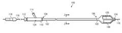
- a pressure relief apparatus for a balloon dilation catheterincludes a shaft having a dilation balloon attached to the distal end of the shaft, an inflation/deflation lumen for inflating and deflating the balloon and a pressure relief port formed through the wall of the inflation/deflation lumen.
- a pressure relief memberis secured across the pressure relief port to form a fluid tight seal.
- the fluid tight sealis configured to fail (e.g. burst, rupture, tear or leak) at a predetermined pressure to release pressure from the inflation/deflation lumen through the pressure relief port.
- the predetermined pressuremay be greater than or equal to the rated burst pressure of the dilation balloon.
Landscapes
- Health & Medical Sciences (AREA)
- Life Sciences & Earth Sciences (AREA)
- Heart & Thoracic Surgery (AREA)
- Hematology (AREA)
- Engineering & Computer Science (AREA)
- Anesthesiology (AREA)
- Biomedical Technology (AREA)
- Animal Behavior & Ethology (AREA)
- General Health & Medical Sciences (AREA)
- Public Health (AREA)
- Veterinary Medicine (AREA)
- Pulmonology (AREA)
- Biophysics (AREA)
- Child & Adolescent Psychology (AREA)
- Vascular Medicine (AREA)
- Media Introduction/Drainage Providing Device (AREA)
Abstract
Description
Claims (19)
Priority Applications (3)
| Application Number | Priority Date | Filing Date | Title |
|---|---|---|---|
| US12/390,573US8814899B2 (en) | 2009-02-23 | 2009-02-23 | Balloon catheter pressure relief valve |
| US14/468,882US20140364893A1 (en) | 2009-02-23 | 2014-08-26 | Balloon catheter pressure relief valve |
| US14/616,328US9259559B2 (en) | 2009-02-23 | 2015-02-06 | Balloon catheter pressure relief valve |
Applications Claiming Priority (1)
| Application Number | Priority Date | Filing Date | Title |
|---|---|---|---|
| US12/390,573US8814899B2 (en) | 2009-02-23 | 2009-02-23 | Balloon catheter pressure relief valve |
Related Child Applications (1)
| Application Number | Title | Priority Date | Filing Date |
|---|---|---|---|
| US14/468,882ContinuationUS20140364893A1 (en) | 2009-02-23 | 2014-08-26 | Balloon catheter pressure relief valve |
Publications (2)
| Publication Number | Publication Date |
|---|---|
| US20100217189A1 US20100217189A1 (en) | 2010-08-26 |
| US8814899B2true US8814899B2 (en) | 2014-08-26 |
Family
ID=42631584
Family Applications (2)
| Application Number | Title | Priority Date | Filing Date |
|---|---|---|---|
| US12/390,573Expired - Fee RelatedUS8814899B2 (en) | 2009-02-23 | 2009-02-23 | Balloon catheter pressure relief valve |
| US14/468,882AbandonedUS20140364893A1 (en) | 2009-02-23 | 2014-08-26 | Balloon catheter pressure relief valve |
Family Applications After (1)
| Application Number | Title | Priority Date | Filing Date |
|---|---|---|---|
| US14/468,882AbandonedUS20140364893A1 (en) | 2009-02-23 | 2014-08-26 | Balloon catheter pressure relief valve |
Country Status (1)
| Country | Link |
|---|---|
| US (2) | US8814899B2 (en) |
Cited By (2)
| Publication number | Priority date | Publication date | Assignee | Title |
|---|---|---|---|---|
| US9872718B2 (en)* | 2012-04-27 | 2018-01-23 | Medtronic Adrian Luxembourg S.a.r.l. | Shafts with pressure relief in cryotherapeutic catheters and associated devices, systems, and methods |
| US20180229013A1 (en)* | 2015-10-29 | 2018-08-16 | Convatec Technologies Inc. | Valve system for inflatable devices |
Families Citing this family (11)
| Publication number | Priority date | Publication date | Assignee | Title |
|---|---|---|---|---|
| WO2013109293A1 (en) | 2011-02-17 | 2013-07-25 | Convatec Technologies Inc. | Valve system for inflatable medical device |
| BR112014011877A2 (en) | 2011-11-16 | 2017-05-16 | Convatec Technologies Inc | device to prevent excessive balloon inflation in catheters and medical airway devices |
| US10653423B2 (en)* | 2012-06-29 | 2020-05-19 | University Of Washington | Catheters for emergency endovascular surgery and associated devices, systems, and methods |
| US10039912B2 (en)* | 2012-07-10 | 2018-08-07 | St. Jude Medical, Atrial Fibrillation Division, Inc. | System and method for coupling a tube with a medical device handle |
| PL3027266T3 (en) | 2013-08-01 | 2023-09-04 | Convatec Technologies Inc. | Self-closing bag connector |
| JP6921003B2 (en) | 2015-05-18 | 2021-08-18 | コンバテック・テクノロジーズ・インコーポレイテッドConvatec Technologies Inc | Spring-loaded bag connector |
| US10835688B2 (en)* | 2017-08-01 | 2020-11-17 | Tejash Patel | Enhanced needle |
| US10595918B2 (en) | 2018-01-08 | 2020-03-24 | Medtronic Holding Company Sàrl | High-pressure balloon catheter with pressure regulating valve |
| CN108465235B (en)* | 2018-03-02 | 2021-10-08 | 广州市雄翔动漫科技有限公司 | Balloon game apparatus and method of use |
| EP4243914A1 (en) | 2020-11-13 | 2023-09-20 | Nagajyothi, K. | Pressure induced deflatable foley's catheter |
| CN113694351B (en)* | 2021-09-18 | 2023-06-20 | 温州市人民医院 | Pressurizing device of double-balloon catheter for repairing air leakage in operation |
Citations (145)
| Publication number | Priority date | Publication date | Assignee | Title |
|---|---|---|---|---|
| US1596284A (en) | 1926-08-17 | malmgren | ||
| US2043083A (en) | 1932-07-08 | 1936-06-02 | Wappler Frederick Charles | Therapeutic electrode and plug therefor |
| US3769981A (en) | 1972-02-09 | 1973-11-06 | Kendall & Co | Urinary catheter |
| US3981415A (en) | 1975-10-29 | 1976-09-21 | E. I. Du Pont De Nemours And Company | Dispenser with expansible member and contracting fabric |
| US4367396A (en) | 1980-07-21 | 1983-01-04 | Pace Incorporated | Thermal tool including twisted tip for the tool and method of making tip |
| US4482516A (en) | 1982-09-10 | 1984-11-13 | W. L. Gore & Associates, Inc. | Process for producing a high strength porous polytetrafluoroethylene product having a coarse microstructure |
| US4572186A (en) | 1983-12-07 | 1986-02-25 | Cordis Corporation | Vessel dilation |
| US4637396A (en) | 1984-10-26 | 1987-01-20 | Cook, Incorporated | Balloon catheter |
| US4652258A (en) | 1984-12-18 | 1987-03-24 | The Kendall Company | Catheter with expansible connector and method |
| US4702252A (en) | 1983-10-13 | 1987-10-27 | Smiths Industries Public Limited Company | Catheters |
| US4704130A (en) | 1985-10-18 | 1987-11-03 | Mitral Medical, International, Inc. | Biocompatible microporous polymeric materials and methods of making same |
| US4706670A (en) | 1985-11-26 | 1987-11-17 | Meadox Surgimed A/S | Dilatation catheter |
| US4748982A (en) | 1987-01-06 | 1988-06-07 | Advanced Cardiovascular Systems, Inc. | Reinforced balloon dilatation catheter with slitted exchange sleeve and method |
| US4796629A (en) | 1987-06-03 | 1989-01-10 | Joseph Grayzel | Stiffened dilation balloon catheter device |
| US4834755A (en) | 1983-04-04 | 1989-05-30 | Pfizer Hospital Products Group, Inc. | Triaxially-braided fabric prosthesis |
| US4884573A (en) | 1988-03-07 | 1989-12-05 | Leocor, Inc. | Very low profile angioplasty balloon catheter with capacity to use steerable, removable guidewire |
| US4952357A (en) | 1988-08-08 | 1990-08-28 | Scimed Life Systems, Inc. | Method of making a polyimide balloon catheter |
| US4983167A (en) | 1988-11-23 | 1991-01-08 | Harvinder Sahota | Balloon catheters |
| US4998421A (en) | 1990-06-28 | 1991-03-12 | E. I. Du Pont De Nemours And Company | Process for elastic stitchbonded fabric |
| US5042985A (en) | 1989-05-11 | 1991-08-27 | Advanced Cardiovascular Systems, Inc. | Dilatation catheter suitable for peripheral arteries |
| US5046497A (en) | 1986-11-14 | 1991-09-10 | Millar Instruments, Inc. | Structure for coupling a guidewire and a catheter |
| US5061273A (en) | 1989-06-01 | 1991-10-29 | Yock Paul G | Angioplasty apparatus facilitating rapid exchanges |
| US5078727A (en) | 1989-07-14 | 1992-01-07 | Hannam Peter H | Catheters |
| US5108415A (en) | 1988-10-04 | 1992-04-28 | Cordis Corporation | Balloons for medical devices and fabrication thereof |
| US5112304A (en) | 1989-03-17 | 1992-05-12 | Angeion Corporation | Balloon catheter |
| US5116360A (en) | 1990-12-27 | 1992-05-26 | Corvita Corporation | Mesh composite graft |
| US5171297A (en) | 1989-03-17 | 1992-12-15 | Angeion Corporation | Balloon catheter |
| US5201706A (en) | 1989-05-09 | 1993-04-13 | Toray Industries, Inc. | Catheter with a balloon reinforced with composite yarn |
| US5207700A (en) | 1988-08-08 | 1993-05-04 | Scimed Life Systems, Inc. | Polyimide balloon catheter and method of forming a balloon therefor |
| US5264260A (en) | 1991-06-20 | 1993-11-23 | Saab Mark A | Dilatation balloon fabricated from low molecular weight polymers |
| US5270086A (en) | 1989-09-25 | 1993-12-14 | Schneider (Usa) Inc. | Multilayer extrusion of angioplasty balloons |
| US5290306A (en) | 1989-11-29 | 1994-03-01 | Cordis Corporation | Puncture resistant balloon catheter |
| US5295960A (en) | 1992-04-01 | 1994-03-22 | Applied Medical Resources Corporation | Catheter with interior balloon |
| US5304340A (en) | 1991-09-06 | 1994-04-19 | C. R. Bard, Inc. | Method of increasing the tensile strength of a dilatation balloon |
| US5306246A (en) | 1990-11-09 | 1994-04-26 | Boston Scientific Corporation | Balloon for medical catheter |
| US5306245A (en) | 1993-02-23 | 1994-04-26 | Advanced Surgical Inc. | Articulating device |
| US5314443A (en) | 1990-06-25 | 1994-05-24 | Meadox Medicals, Inc. | Prostate balloon dilatation catheter |
| US5344401A (en) | 1991-12-20 | 1994-09-06 | Interventional Technologies Inc. | Catheter balloon formed from a polymeric composite |
| US5358486A (en) | 1987-01-09 | 1994-10-25 | C. R. Bard, Inc. | Multiple layer high strength balloon for dilatation catheter |
| US5410797A (en) | 1992-07-27 | 1995-05-02 | Medtronic, Inc. | Method of making a catheter with flexible side port entry |
| US5451233A (en) | 1986-04-15 | 1995-09-19 | Yock; Paul G. | Angioplasty apparatus facilitating rapid exchanges |
| US5451209A (en) | 1992-05-11 | 1995-09-19 | Advanced Cardiovascular Systems, Inc. | Intraluminal catheter with a composite shaft |
| US5464394A (en) | 1993-06-08 | 1995-11-07 | American Biomed, Inc. | Multilumen percutaneous angioscopy catheter |
| US5470314A (en) | 1994-07-22 | 1995-11-28 | Walinsky; Paul | Perfusion balloon catheter with differential compliance |
| US5477886A (en) | 1991-11-14 | 1995-12-26 | J. Van Beugen Beheer B.V. | Inflatable closing plug for pipes and method of manufacturing same |
| US5478320A (en) | 1989-11-29 | 1995-12-26 | Cordis Corporation | Puncture resistant balloon catheter and method of manufacturing |
| US5492532A (en) | 1989-03-17 | 1996-02-20 | B. Braun Medical, Inc. | Balloon catheter |
| US5549552A (en) | 1995-03-02 | 1996-08-27 | Scimed Life Systems, Inc. | Balloon dilation catheter with improved pushability, trackability and crossability |
| US5549556A (en) | 1992-11-19 | 1996-08-27 | Medtronic, Inc. | Rapid exchange catheter with external wire lumen |
| US5554120A (en) | 1994-07-25 | 1996-09-10 | Advanced Cardiovascular Systems, Inc. | Polymer blends for use in making medical devices including catheters and balloons for dilatation catheters |
| US5575771A (en) | 1995-04-24 | 1996-11-19 | Walinsky; Paul | Balloon catheter with external guidewire |
| US5587125A (en) | 1994-08-15 | 1996-12-24 | Schneider (Usa) Inc. | Non-coextrusion method of making multi-layer angioplasty balloons |
| US5599576A (en) | 1995-02-06 | 1997-02-04 | Surface Solutions Laboratories, Inc. | Medical apparatus with scratch-resistant coating and method of making same |
| US5599578A (en) | 1986-04-30 | 1997-02-04 | Butland; Charles L. | Technique for labeling an object for its identification and/or verification |
| US5647848A (en) | 1995-06-07 | 1997-07-15 | Meadox Medicals, Inc. | High strength low compliance composite balloon for balloon catheters |
| US5690642A (en) | 1996-01-18 | 1997-11-25 | Cook Incorporated | Rapid exchange stent delivery balloon catheter |
| US5728063A (en) | 1994-11-23 | 1998-03-17 | Micro International Systems, Inc. | High torque balloon catheter |
| US5728083A (en) | 1994-06-30 | 1998-03-17 | Mcneil-Ppc, Inc. | Multilayered absorbent structures |
| US5741325A (en) | 1993-10-01 | 1998-04-21 | Emory University | Self-expanding intraluminal composite prosthesis |
| US5752934A (en) | 1995-09-18 | 1998-05-19 | W. L. Gore & Associates, Inc. | Balloon catheter device |
| US5759172A (en) | 1995-04-10 | 1998-06-02 | Cordis Corporation | Balloon catheter with lobed balloon and method for manufacturing such a catheter |
| US5769817A (en) | 1997-02-28 | 1998-06-23 | Schneider (Usa) Inc. | Coextruded balloon and method of making same |
| US5772681A (en) | 1993-03-02 | 1998-06-30 | Metra Aps | Dilation catheter |
| US5788979A (en) | 1994-07-22 | 1998-08-04 | Inflow Dynamics Inc. | Biodegradable coating with inhibitory properties for application to biocompatible materials |
| US5797877A (en) | 1993-10-01 | 1998-08-25 | Boston Scientific Corporation | Medical device balloons containing thermoplastic elastomers |
| US5820613A (en) | 1995-01-31 | 1998-10-13 | Cordis Corporation | Balloon catheter with reinforced and elastically deformable basic body |
| US5868779A (en) | 1997-08-15 | 1999-02-09 | Ruiz; Carlos E. | Apparatus and methods for dilating vessels and hollow-body organs |
| US5879369A (en) | 1995-10-11 | 1999-03-09 | Terumo Kabushiki Kaisha | Catheter balloon and balloon catheter |
| US5928181A (en) | 1997-11-21 | 1999-07-27 | Advanced International Technologies, Inc. | Cardiac bypass catheter system and method of use |
| US5972441A (en) | 1993-08-18 | 1999-10-26 | W. L. Gore & Associates, Inc. | Thin-wall polytetrafluoroethylene tube |
| US5980486A (en) | 1989-01-30 | 1999-11-09 | Arterial Vascular Engineering, Inc. | Rapidly exchangeable coronary catheter |
| US6007544A (en) | 1996-06-14 | 1999-12-28 | Beth Israel Deaconess Medical Center | Catheter apparatus having an improved shape-memory alloy cuff and inflatable on-demand balloon for creating a bypass graft in-vivo |
| US6010480A (en) | 1993-08-23 | 2000-01-04 | Boston Scientific Corporation | Balloon catheter |
| US6012457A (en) | 1997-07-08 | 2000-01-11 | The Regents Of The University Of California | Device and method for forming a circumferential conduction block in a pulmonary vein |
| US6015430A (en) | 1987-12-08 | 2000-01-18 | Wall; William H. | Expandable stent having a fabric liner |
| US6024772A (en) | 1996-08-16 | 2000-02-15 | Nec Corporation | Solid electrolyte capacitor and method of manufacturing the same |
| US6024740A (en) | 1997-07-08 | 2000-02-15 | The Regents Of The University Of California | Circumferential ablation device assembly |
| US6027779A (en) | 1993-08-18 | 2000-02-22 | W. L. Gore & Associates, Inc. | Thin-wall polytetrafluoroethylene tube |
| US6036697A (en) | 1998-07-09 | 2000-03-14 | Scimed Life Systems, Inc. | Balloon catheter with balloon inflation at distal end of balloon |
| US6117101A (en) | 1997-07-08 | 2000-09-12 | The Regents Of The University Of California | Circumferential ablation device assembly |
| US6124007A (en) | 1996-03-06 | 2000-09-26 | Scimed Life Systems Inc | Laminate catheter balloons with additive burst strength and methods for preparation of same |
| US6127597A (en) | 1997-03-07 | 2000-10-03 | Discotech N.V. | Systems for percutaneous bone and spinal stabilization, fixation and repair |
| US6156254A (en) | 1996-08-02 | 2000-12-05 | Ranier Limited | Method of manufacturing a balloon member for a balloon catheter |
| US6159238A (en) | 1998-03-04 | 2000-12-12 | Scimed Life Systems, Inc | Stent having variable properties and method of its use |
| US6164283A (en) | 1997-07-08 | 2000-12-26 | The Regents Of The University Of California | Device and method for forming a circumferential conduction block in a pulmonary vein |
| US6171297B1 (en) | 1998-06-30 | 2001-01-09 | Schneider (Usa) Inc | Radiopaque catheter tip |
| US6183492B1 (en) | 1997-08-28 | 2001-02-06 | Charles C. Hart | Perfusion-isolation catheter apparatus and method |
| US6187013B1 (en) | 1994-06-06 | 2001-02-13 | Meadox Medicals, Inc. | Catheter with stent and method for the production of a catheter with stent |
| US6186978B1 (en) | 1996-08-07 | 2001-02-13 | Target Therapeutics, Inc. | Braid reinforced infusion catheter with inflatable membrane |
| US6188978B1 (en) | 1998-01-13 | 2001-02-13 | Nec Corporation | Voice encoding/decoding apparatus coping with modem signal |
| US6213995B1 (en) | 1999-08-31 | 2001-04-10 | Phelps Dodge High Performance Conductors Of Sc And Ga, Inc. | Flexible tubing with braided signal transmission elements |
| US6234995B1 (en) | 1998-11-12 | 2001-05-22 | Advanced Interventional Technologies, Inc. | Apparatus and method for selectively isolating a proximal anastomosis site from blood in an aorta |
| US6245064B1 (en) | 1997-07-08 | 2001-06-12 | Atrionix, Inc. | Circumferential ablation device assembly |
| US6263236B1 (en) | 1999-11-29 | 2001-07-17 | Illumenex Corporation | Non-occlusive expandable catheter |
| US6270902B1 (en) | 1997-04-23 | 2001-08-07 | C. R. Bard, Inc. | Method of improving the adherence of certain crosslinked polymer coatings containing PEO or PVP to a substrate |
| US6290485B1 (en) | 1995-03-02 | 2001-09-18 | Lixiao Wang | Mold for forming a balloon catheter having stepped compliance curve |
| US6306154B1 (en) | 1997-06-18 | 2001-10-23 | Bhk Holding | Hemostatic system for body cavities |
| US6309379B1 (en) | 1991-05-23 | 2001-10-30 | Lloyd K. Willard | Sheath for selective delivery of multiple intravascular devices and methods of use thereof |
| US6315751B1 (en) | 1997-08-15 | 2001-11-13 | Cleveland Clinic Foundation | Cardiopulmonary bypass system using vacuum assisted venous drainage |
| US6361529B1 (en) | 1998-09-09 | 2002-03-26 | Schneider (Usa) Inc. | Stiffening member in a rapid exchange dilation catheter |
| US20020058960A1 (en) | 1998-04-08 | 2002-05-16 | Hudson John Overton | Hemostatic system for body cavities |
| US6394995B1 (en) | 1998-05-15 | 2002-05-28 | X Technologies Inc. | Enhanced balloon dilatation system |
| US20020077653A1 (en) | 1998-04-08 | 2002-06-20 | Hudson John Overton | Hemostatic system for body cavities |
| US20020161388A1 (en) | 2001-02-27 | 2002-10-31 | Samuels Sam L. | Elastomeric balloon support fabric |
| US6544219B2 (en) | 2000-12-15 | 2003-04-08 | Advanced Cardiovascular Systems, Inc. | Catheter for placement of therapeutic devices at the ostium of a bifurcation of a body lumen |
| US6626889B1 (en) | 2001-07-25 | 2003-09-30 | Advanced Cardiovascular Systems, Inc. | Thin-walled guiding catheter with improved radiopacity |
| US6663648B1 (en) | 2000-06-15 | 2003-12-16 | Cordis Corporation | Balloon catheter with floating stiffener, and procedure |
| US20040015182A1 (en) | 1992-06-02 | 2004-01-22 | Kieturakis Maciej J. | Apparatus and method for developing an anatomic space for laparoscopic procedures with laparoscopic visualization |
| US20040039332A1 (en) | 2002-08-23 | 2004-02-26 | Medtronic Ave, Inc. | Catheter having a low-friction guidewire lumen and method of manufacture |
| US6702750B2 (en) | 1986-04-15 | 2004-03-09 | Cardiovascular Imaging Systems, Inc. | Angioplasty apparatus facilitating rapid exchanges and methods |
| US6702782B2 (en) | 2001-06-26 | 2004-03-09 | Concentric Medical, Inc. | Large lumen balloon catheter |
| US20040073163A1 (en) | 2001-07-30 | 2004-04-15 | Scimed Life Systems, Inc. | Chronic total occlusion device with variable stiffness shaft |
| US20040073299A1 (en) | 2000-12-16 | 2004-04-15 | Hudson John Overton | Hemostatic device |
| US20040082965A1 (en) | 1996-06-14 | 2004-04-29 | Beckham James P. | Medical balloon |
| US6733487B2 (en) | 1990-08-28 | 2004-05-11 | Scimed Life Systems, Inc. | Balloon catheter with distal guide wire lumen |
| US6743196B2 (en) | 1999-03-01 | 2004-06-01 | Coaxia, Inc. | Partial aortic occlusion devices and methods for cerebral perfusion augmentation |
| US6748425B1 (en) | 2000-01-04 | 2004-06-08 | International Business Machines Corporation | System and method for browser creation and maintenance of forms |
| US6755845B2 (en) | 1992-06-02 | 2004-06-29 | General Surgical Innovations, Inc. | Apparatus and method for developing an anatomic space for laparoscopic hernia repair and patch for use therewith |
| US6761708B1 (en) | 2000-10-31 | 2004-07-13 | Advanced Cardiovascular Systems, Inc. | Radiopaque marker for a catheter and method of making |
| US20040176740A1 (en) | 2003-03-05 | 2004-09-09 | Scimed Life Systems, Inc. | Multi-braid exterior tube |
| US20050027249A1 (en) | 1991-04-05 | 2005-02-03 | Boston Scientific Corporation, A Delaware Corporation | Adjustably stiffenable convertible catheter assembly |
| US20050033225A1 (en) | 2003-08-08 | 2005-02-10 | Scimed Life Systems, Inc. | Catheter shaft for regulation of inflation and deflation |
| US20050102020A1 (en) | 2000-07-24 | 2005-05-12 | Jeffrey Grayzel | Stiffened balloon catheter for dilatation and stenting |
| US6899713B2 (en) | 2000-06-23 | 2005-05-31 | Vertelink Corporation | Formable orthopedic fixation system |
| US20050123702A1 (en) | 2003-12-03 | 2005-06-09 | Jim Beckham | Non-compliant medical balloon having a longitudinal fiber layer |
| US20050121073A1 (en)* | 2003-12-05 | 2005-06-09 | Hose Shop, Ltd. | Burst disk assembly |
| US6905743B1 (en) | 1999-02-25 | 2005-06-14 | Boston Scientific Scimed, Inc. | Dimensionally stable balloons |
| US6911038B2 (en) | 2001-05-08 | 2005-06-28 | Scimed Life Systems, Inc. | Matched balloon to stent shortening |
| US20050267408A1 (en) | 2004-05-27 | 2005-12-01 | Axel Grandt | Catheter having first and second guidewire tubes and overlapping stiffening members |
| US20050271844A1 (en) | 2004-06-07 | 2005-12-08 | Scimed Life Systems, Inc. | Artificial silk reinforcement of PTCA balloon |
| US6977103B2 (en) | 1999-10-25 | 2005-12-20 | Boston Scientific Scimed, Inc. | Dimensionally stable balloons |
| US20060085022A1 (en) | 2004-10-15 | 2006-04-20 | Kelli Hayes | Non-compliant medical balloon having an integral woven fabric layer |
| US20060085024A1 (en) | 2004-10-15 | 2006-04-20 | Pepper Lanny R | Non-compliant medical balloon having an integral non-woven fabric layer |
| US20060085023A1 (en) | 2004-10-15 | 2006-04-20 | Davies William F Jr | Medical balloon having strengthening rods |
| US20070010847A1 (en) | 2005-06-22 | 2007-01-11 | Futurematrix Interventional, Inc. | Balloon dilation catheter having transition from coaxial lumens to non-coaxial multiple lumens |
| US20070016133A1 (en) | 2005-07-05 | 2007-01-18 | Futurematrix Interventional, Inc. | Rapid exchange balloon dilation catheter having reinforced multi-lumen distal portion |
| US7252650B1 (en) | 1996-08-02 | 2007-08-07 | Ranier Limited | Balloon catheter |
| US7300415B2 (en) | 2002-12-20 | 2007-11-27 | Advanced Cardiovascular Systems, Inc. | Balloon catheter having an external guidewire |
| US20080009793A1 (en)* | 2005-04-21 | 2008-01-10 | Dabbs Clifton R | Foley Catheter Adaptor |
| US20080082050A1 (en) | 2006-05-11 | 2008-04-03 | Solar Ronald J | Systems and methods for treating a vessel using focused force |
| US20080183132A1 (en) | 2004-10-15 | 2008-07-31 | Futurematrix Interventional, Inc. | Non-compliant medical balloon having braided or knitted reinforcement |
| US7435254B2 (en) | 2000-01-31 | 2008-10-14 | Scimed Life Systems, Inc. | Braided endoluminal device having tapered filaments |
| US20090043254A1 (en) | 2007-08-06 | 2009-02-12 | Pepper Lanny R | Non-compliant medical balloon |
| US20090082778A1 (en)* | 2007-09-25 | 2009-03-26 | Correx, Inc. | Applicator, assembly, and method for connecting an inlet conduit to a hollow organ |
| US7635510B2 (en) | 2004-07-07 | 2009-12-22 | Boston Scientific Scimed, Inc. | High performance balloon catheter/component |
Family Cites Families (1)
| Publication number | Priority date | Publication date | Assignee | Title |
|---|---|---|---|---|
| US4837396A (en)* | 1987-12-11 | 1989-06-06 | Mobil Oil Corporation | Zeolite beta containing hydrocarbon conversion catalyst of stability |
- 2009
- 2009-02-23USUS12/390,573patent/US8814899B2/ennot_activeExpired - Fee Related
- 2014
- 2014-08-26USUS14/468,882patent/US20140364893A1/ennot_activeAbandoned
Patent Citations (174)
| Publication number | Priority date | Publication date | Assignee | Title |
|---|---|---|---|---|
| US1596284A (en) | 1926-08-17 | malmgren | ||
| US2043083A (en) | 1932-07-08 | 1936-06-02 | Wappler Frederick Charles | Therapeutic electrode and plug therefor |
| US3769981A (en) | 1972-02-09 | 1973-11-06 | Kendall & Co | Urinary catheter |
| US3981415A (en) | 1975-10-29 | 1976-09-21 | E. I. Du Pont De Nemours And Company | Dispenser with expansible member and contracting fabric |
| US4367396A (en) | 1980-07-21 | 1983-01-04 | Pace Incorporated | Thermal tool including twisted tip for the tool and method of making tip |
| US4482516A (en) | 1982-09-10 | 1984-11-13 | W. L. Gore & Associates, Inc. | Process for producing a high strength porous polytetrafluoroethylene product having a coarse microstructure |
| US4834755A (en) | 1983-04-04 | 1989-05-30 | Pfizer Hospital Products Group, Inc. | Triaxially-braided fabric prosthesis |
| US4702252A (en) | 1983-10-13 | 1987-10-27 | Smiths Industries Public Limited Company | Catheters |
| US4572186A (en) | 1983-12-07 | 1986-02-25 | Cordis Corporation | Vessel dilation |
| US4637396A (en) | 1984-10-26 | 1987-01-20 | Cook, Incorporated | Balloon catheter |
| US4652258A (en) | 1984-12-18 | 1987-03-24 | The Kendall Company | Catheter with expansible connector and method |
| US4704130A (en) | 1985-10-18 | 1987-11-03 | Mitral Medical, International, Inc. | Biocompatible microporous polymeric materials and methods of making same |
| US4706670A (en) | 1985-11-26 | 1987-11-17 | Meadox Surgimed A/S | Dilatation catheter |
| US6036715A (en) | 1986-04-15 | 2000-03-14 | Yock; Paul G. | Angioplasty apparatus facilitating rapid exchanges |
| US5451233A (en) | 1986-04-15 | 1995-09-19 | Yock; Paul G. | Angioplasty apparatus facilitating rapid exchanges |
| US6702750B2 (en) | 1986-04-15 | 2004-03-09 | Cardiovascular Imaging Systems, Inc. | Angioplasty apparatus facilitating rapid exchanges and methods |
| US5599578A (en) | 1986-04-30 | 1997-02-04 | Butland; Charles L. | Technique for labeling an object for its identification and/or verification |
| US5046497A (en) | 1986-11-14 | 1991-09-10 | Millar Instruments, Inc. | Structure for coupling a guidewire and a catheter |
| US4748982A (en) | 1987-01-06 | 1988-06-07 | Advanced Cardiovascular Systems, Inc. | Reinforced balloon dilatation catheter with slitted exchange sleeve and method |
| US5755690A (en) | 1987-01-09 | 1998-05-26 | C. R. Bard | Multiple layer high strength balloon for dilatation catheter |
| US5358486A (en) | 1987-01-09 | 1994-10-25 | C. R. Bard, Inc. | Multiple layer high strength balloon for dilatation catheter |
| US4796629A (en) | 1987-06-03 | 1989-01-10 | Joseph Grayzel | Stiffened dilation balloon catheter device |
| US6015430A (en) | 1987-12-08 | 2000-01-18 | Wall; William H. | Expandable stent having a fabric liner |
| US4884573A (en) | 1988-03-07 | 1989-12-05 | Leocor, Inc. | Very low profile angioplasty balloon catheter with capacity to use steerable, removable guidewire |
| US4952357A (en) | 1988-08-08 | 1990-08-28 | Scimed Life Systems, Inc. | Method of making a polyimide balloon catheter |
| US5207700A (en) | 1988-08-08 | 1993-05-04 | Scimed Life Systems, Inc. | Polyimide balloon catheter and method of forming a balloon therefor |
| US5108415A (en) | 1988-10-04 | 1992-04-28 | Cordis Corporation | Balloons for medical devices and fabrication thereof |
| US4983167A (en) | 1988-11-23 | 1991-01-08 | Harvinder Sahota | Balloon catheters |
| US5980486A (en) | 1989-01-30 | 1999-11-09 | Arterial Vascular Engineering, Inc. | Rapidly exchangeable coronary catheter |
| US6129708A (en) | 1989-01-30 | 2000-10-10 | Medtronic Ave, Inc. | Rapidly exchangeable coronary catheter |
| US5338299A (en) | 1989-03-17 | 1994-08-16 | Angeion Corporation | Balloon catheter |
| US5171297A (en) | 1989-03-17 | 1992-12-15 | Angeion Corporation | Balloon catheter |
| US5492532A (en) | 1989-03-17 | 1996-02-20 | B. Braun Medical, Inc. | Balloon catheter |
| US5112304A (en) | 1989-03-17 | 1992-05-12 | Angeion Corporation | Balloon catheter |
| US5330429A (en) | 1989-05-09 | 1994-07-19 | Toray Industries, Inc. | Catheter with a balloon reinforced with composite yarn |
| US5201706A (en) | 1989-05-09 | 1993-04-13 | Toray Industries, Inc. | Catheter with a balloon reinforced with composite yarn |
| US5042985A (en) | 1989-05-11 | 1991-08-27 | Advanced Cardiovascular Systems, Inc. | Dilatation catheter suitable for peripheral arteries |
| US5061273A (en) | 1989-06-01 | 1991-10-29 | Yock Paul G | Angioplasty apparatus facilitating rapid exchanges |
| US5078727A (en) | 1989-07-14 | 1992-01-07 | Hannam Peter H | Catheters |
| US5270086A (en) | 1989-09-25 | 1993-12-14 | Schneider (Usa) Inc. | Multilayer extrusion of angioplasty balloons |
| US5478320A (en) | 1989-11-29 | 1995-12-26 | Cordis Corporation | Puncture resistant balloon catheter and method of manufacturing |
| US5620649A (en) | 1989-11-29 | 1997-04-15 | Cordis Corporation | Puncture resistant balloon catheter |
| US5290306A (en) | 1989-11-29 | 1994-03-01 | Cordis Corporation | Puncture resistant balloon catheter |
| US5314443A (en) | 1990-06-25 | 1994-05-24 | Meadox Medicals, Inc. | Prostate balloon dilatation catheter |
| US4998421A (en) | 1990-06-28 | 1991-03-12 | E. I. Du Pont De Nemours And Company | Process for elastic stitchbonded fabric |
| US6733487B2 (en) | 1990-08-28 | 2004-05-11 | Scimed Life Systems, Inc. | Balloon catheter with distal guide wire lumen |
| US5306246A (en) | 1990-11-09 | 1994-04-26 | Boston Scientific Corporation | Balloon for medical catheter |
| US5116360A (en) | 1990-12-27 | 1992-05-26 | Corvita Corporation | Mesh composite graft |
| US20050027249A1 (en) | 1991-04-05 | 2005-02-03 | Boston Scientific Corporation, A Delaware Corporation | Adjustably stiffenable convertible catheter assembly |
| US6309379B1 (en) | 1991-05-23 | 2001-10-30 | Lloyd K. Willard | Sheath for selective delivery of multiple intravascular devices and methods of use thereof |
| US5264260A (en) | 1991-06-20 | 1993-11-23 | Saab Mark A | Dilatation balloon fabricated from low molecular weight polymers |
| US5304340A (en) | 1991-09-06 | 1994-04-19 | C. R. Bard, Inc. | Method of increasing the tensile strength of a dilatation balloon |
| US5477886A (en) | 1991-11-14 | 1995-12-26 | J. Van Beugen Beheer B.V. | Inflatable closing plug for pipes and method of manufacturing same |
| US5344401A (en) | 1991-12-20 | 1994-09-06 | Interventional Technologies Inc. | Catheter balloon formed from a polymeric composite |
| US5295960A (en) | 1992-04-01 | 1994-03-22 | Applied Medical Resources Corporation | Catheter with interior balloon |
| US5451209A (en) | 1992-05-11 | 1995-09-19 | Advanced Cardiovascular Systems, Inc. | Intraluminal catheter with a composite shaft |
| US20040015182A1 (en) | 1992-06-02 | 2004-01-22 | Kieturakis Maciej J. | Apparatus and method for developing an anatomic space for laparoscopic procedures with laparoscopic visualization |
| US6755845B2 (en) | 1992-06-02 | 2004-06-29 | General Surgical Innovations, Inc. | Apparatus and method for developing an anatomic space for laparoscopic hernia repair and patch for use therewith |
| US5410797A (en) | 1992-07-27 | 1995-05-02 | Medtronic, Inc. | Method of making a catheter with flexible side port entry |
| US5549556A (en) | 1992-11-19 | 1996-08-27 | Medtronic, Inc. | Rapid exchange catheter with external wire lumen |
| US5306245A (en) | 1993-02-23 | 1994-04-26 | Advanced Surgical Inc. | Articulating device |
| US5772681A (en) | 1993-03-02 | 1998-06-30 | Metra Aps | Dilation catheter |
| US5464394A (en) | 1993-06-08 | 1995-11-07 | American Biomed, Inc. | Multilumen percutaneous angioscopy catheter |
| US5972441A (en) | 1993-08-18 | 1999-10-26 | W. L. Gore & Associates, Inc. | Thin-wall polytetrafluoroethylene tube |
| US6027779A (en) | 1993-08-18 | 2000-02-22 | W. L. Gore & Associates, Inc. | Thin-wall polytetrafluoroethylene tube |
| US6010480A (en) | 1993-08-23 | 2000-01-04 | Boston Scientific Corporation | Balloon catheter |
| US5797877A (en) | 1993-10-01 | 1998-08-25 | Boston Scientific Corporation | Medical device balloons containing thermoplastic elastomers |
| US5741325A (en) | 1993-10-01 | 1998-04-21 | Emory University | Self-expanding intraluminal composite prosthesis |
| US6187013B1 (en) | 1994-06-06 | 2001-02-13 | Meadox Medicals, Inc. | Catheter with stent and method for the production of a catheter with stent |
| US5728083A (en) | 1994-06-30 | 1998-03-17 | Mcneil-Ppc, Inc. | Multilayered absorbent structures |
| US5788979A (en) | 1994-07-22 | 1998-08-04 | Inflow Dynamics Inc. | Biodegradable coating with inhibitory properties for application to biocompatible materials |
| US5470314A (en) | 1994-07-22 | 1995-11-28 | Walinsky; Paul | Perfusion balloon catheter with differential compliance |
| US5554120A (en) | 1994-07-25 | 1996-09-10 | Advanced Cardiovascular Systems, Inc. | Polymer blends for use in making medical devices including catheters and balloons for dilatation catheters |
| US5587125A (en) | 1994-08-15 | 1996-12-24 | Schneider (Usa) Inc. | Non-coextrusion method of making multi-layer angioplasty balloons |
| US5728063A (en) | 1994-11-23 | 1998-03-17 | Micro International Systems, Inc. | High torque balloon catheter |
| US5820613A (en) | 1995-01-31 | 1998-10-13 | Cordis Corporation | Balloon catheter with reinforced and elastically deformable basic body |
| US5599576A (en) | 1995-02-06 | 1997-02-04 | Surface Solutions Laboratories, Inc. | Medical apparatus with scratch-resistant coating and method of making same |
| US5549552A (en) | 1995-03-02 | 1996-08-27 | Scimed Life Systems, Inc. | Balloon dilation catheter with improved pushability, trackability and crossability |
| US6290485B1 (en) | 1995-03-02 | 2001-09-18 | Lixiao Wang | Mold for forming a balloon catheter having stepped compliance curve |
| US5759172A (en) | 1995-04-10 | 1998-06-02 | Cordis Corporation | Balloon catheter with lobed balloon and method for manufacturing such a catheter |
| US5575771A (en) | 1995-04-24 | 1996-11-19 | Walinsky; Paul | Balloon catheter with external guidewire |
| US5647848A (en) | 1995-06-07 | 1997-07-15 | Meadox Medicals, Inc. | High strength low compliance composite balloon for balloon catheters |
| US5752934A (en) | 1995-09-18 | 1998-05-19 | W. L. Gore & Associates, Inc. | Balloon catheter device |
| US5879369A (en) | 1995-10-11 | 1999-03-09 | Terumo Kabushiki Kaisha | Catheter balloon and balloon catheter |
| US5690642A (en) | 1996-01-18 | 1997-11-25 | Cook Incorporated | Rapid exchange stent delivery balloon catheter |
| US6124007A (en) | 1996-03-06 | 2000-09-26 | Scimed Life Systems Inc | Laminate catheter balloons with additive burst strength and methods for preparation of same |
| US6328925B1 (en) | 1996-03-06 | 2001-12-11 | Scimed Life Systems, Inc. | Laminate catheter balloons with additive burst strength and methods for preparation of same |
| US20070093865A1 (en) | 1996-06-14 | 2007-04-26 | C.R.Bard | Medical balloon |
| US6746425B1 (en) | 1996-06-14 | 2004-06-08 | Futuremed Interventional | Medical balloon |
| US6007544A (en) | 1996-06-14 | 1999-12-28 | Beth Israel Deaconess Medical Center | Catheter apparatus having an improved shape-memory alloy cuff and inflatable on-demand balloon for creating a bypass graft in-vivo |
| US20040082965A1 (en) | 1996-06-14 | 2004-04-29 | Beckham James P. | Medical balloon |
| US20040109964A1 (en) | 1996-06-14 | 2004-06-10 | Beckham James P. | Medical balloon |
| US20070059466A1 (en) | 1996-06-14 | 2007-03-15 | C.R.Bard | Medical balloon |
| US6156254A (en) | 1996-08-02 | 2000-12-05 | Ranier Limited | Method of manufacturing a balloon member for a balloon catheter |
| US7252650B1 (en) | 1996-08-02 | 2007-08-07 | Ranier Limited | Balloon catheter |
| US6186978B1 (en) | 1996-08-07 | 2001-02-13 | Target Therapeutics, Inc. | Braid reinforced infusion catheter with inflatable membrane |
| US6024772A (en) | 1996-08-16 | 2000-02-15 | Nec Corporation | Solid electrolyte capacitor and method of manufacturing the same |
| US5769817A (en) | 1997-02-28 | 1998-06-23 | Schneider (Usa) Inc. | Coextruded balloon and method of making same |
| US6127597A (en) | 1997-03-07 | 2000-10-03 | Discotech N.V. | Systems for percutaneous bone and spinal stabilization, fixation and repair |
| US6270902B1 (en) | 1997-04-23 | 2001-08-07 | C. R. Bard, Inc. | Method of improving the adherence of certain crosslinked polymer coatings containing PEO or PVP to a substrate |
| US6254599B1 (en) | 1997-05-09 | 2001-07-03 | Atrionix, Inc. | Circumferential ablation device assembly |
| US6306154B1 (en) | 1997-06-18 | 2001-10-23 | Bhk Holding | Hemostatic system for body cavities |
| US6012457A (en) | 1997-07-08 | 2000-01-11 | The Regents Of The University Of California | Device and method for forming a circumferential conduction block in a pulmonary vein |
| US6305378B1 (en) | 1997-07-08 | 2001-10-23 | The Regents Of The University Of California | Device and method for forming a circumferential conduction block in a pulmonary vein |
| US6024740A (en) | 1997-07-08 | 2000-02-15 | The Regents Of The University Of California | Circumferential ablation device assembly |
| US6245064B1 (en) | 1997-07-08 | 2001-06-12 | Atrionix, Inc. | Circumferential ablation device assembly |
| US6164283A (en) | 1997-07-08 | 2000-12-26 | The Regents Of The University Of California | Device and method for forming a circumferential conduction block in a pulmonary vein |
| US6117101A (en) | 1997-07-08 | 2000-09-12 | The Regents Of The University Of California | Circumferential ablation device assembly |
| US6315751B1 (en) | 1997-08-15 | 2001-11-13 | Cleveland Clinic Foundation | Cardiopulmonary bypass system using vacuum assisted venous drainage |
| US5868779A (en) | 1997-08-15 | 1999-02-09 | Ruiz; Carlos E. | Apparatus and methods for dilating vessels and hollow-body organs |
| US6183492B1 (en) | 1997-08-28 | 2001-02-06 | Charles C. Hart | Perfusion-isolation catheter apparatus and method |
| US5928181A (en) | 1997-11-21 | 1999-07-27 | Advanced International Technologies, Inc. | Cardiac bypass catheter system and method of use |
| US6188978B1 (en) | 1998-01-13 | 2001-02-13 | Nec Corporation | Voice encoding/decoding apparatus coping with modem signal |
| US6159238A (en) | 1998-03-04 | 2000-12-12 | Scimed Life Systems, Inc | Stent having variable properties and method of its use |
| US20020058960A1 (en) | 1998-04-08 | 2002-05-16 | Hudson John Overton | Hemostatic system for body cavities |
| US20020077653A1 (en) | 1998-04-08 | 2002-06-20 | Hudson John Overton | Hemostatic system for body cavities |
| US6706051B2 (en) | 1998-04-08 | 2004-03-16 | Bhk Holding, Ltd. | Hemostatic system for body cavities |
| US6394995B1 (en) | 1998-05-15 | 2002-05-28 | X Technologies Inc. | Enhanced balloon dilatation system |
| US6171297B1 (en) | 1998-06-30 | 2001-01-09 | Schneider (Usa) Inc | Radiopaque catheter tip |
| US6036697A (en) | 1998-07-09 | 2000-03-14 | Scimed Life Systems, Inc. | Balloon catheter with balloon inflation at distal end of balloon |
| US6361529B1 (en) | 1998-09-09 | 2002-03-26 | Schneider (Usa) Inc. | Stiffening member in a rapid exchange dilation catheter |
| US6234995B1 (en) | 1998-11-12 | 2001-05-22 | Advanced Interventional Technologies, Inc. | Apparatus and method for selectively isolating a proximal anastomosis site from blood in an aorta |
| US6905743B1 (en) | 1999-02-25 | 2005-06-14 | Boston Scientific Scimed, Inc. | Dimensionally stable balloons |
| US6743196B2 (en) | 1999-03-01 | 2004-06-01 | Coaxia, Inc. | Partial aortic occlusion devices and methods for cerebral perfusion augmentation |
| US6213995B1 (en) | 1999-08-31 | 2001-04-10 | Phelps Dodge High Performance Conductors Of Sc And Ga, Inc. | Flexible tubing with braided signal transmission elements |
| US6977103B2 (en) | 1999-10-25 | 2005-12-20 | Boston Scientific Scimed, Inc. | Dimensionally stable balloons |
| US6263236B1 (en) | 1999-11-29 | 2001-07-17 | Illumenex Corporation | Non-occlusive expandable catheter |
| US6748425B1 (en) | 2000-01-04 | 2004-06-08 | International Business Machines Corporation | System and method for browser creation and maintenance of forms |
| US7435254B2 (en) | 2000-01-31 | 2008-10-14 | Scimed Life Systems, Inc. | Braided endoluminal device having tapered filaments |
| US6663648B1 (en) | 2000-06-15 | 2003-12-16 | Cordis Corporation | Balloon catheter with floating stiffener, and procedure |
| US6899713B2 (en) | 2000-06-23 | 2005-05-31 | Vertelink Corporation | Formable orthopedic fixation system |
| US20060015133A1 (en) | 2000-07-24 | 2006-01-19 | Jeffrey Grayzel | Stiffened balloon catheter for dilatation and stenting |
| US7662163B2 (en) | 2000-07-24 | 2010-02-16 | Jeffrey Grayzel | Stiffened balloon apparatus with increased flexibility |
| US20050102020A1 (en) | 2000-07-24 | 2005-05-12 | Jeffrey Grayzel | Stiffened balloon catheter for dilatation and stenting |
| US6942680B2 (en) | 2000-07-24 | 2005-09-13 | Jeffrey Grayzel | Stiffened balloon catheter for dilatation and stenting |
| US6761708B1 (en) | 2000-10-31 | 2004-07-13 | Advanced Cardiovascular Systems, Inc. | Radiopaque marker for a catheter and method of making |
| US6544219B2 (en) | 2000-12-15 | 2003-04-08 | Advanced Cardiovascular Systems, Inc. | Catheter for placement of therapeutic devices at the ostium of a bifurcation of a body lumen |
| US20040073299A1 (en) | 2000-12-16 | 2004-04-15 | Hudson John Overton | Hemostatic device |
| US20020161388A1 (en) | 2001-02-27 | 2002-10-31 | Samuels Sam L. | Elastomeric balloon support fabric |
| US6911038B2 (en) | 2001-05-08 | 2005-06-28 | Scimed Life Systems, Inc. | Matched balloon to stent shortening |
| US6702782B2 (en) | 2001-06-26 | 2004-03-09 | Concentric Medical, Inc. | Large lumen balloon catheter |
| US6626889B1 (en) | 2001-07-25 | 2003-09-30 | Advanced Cardiovascular Systems, Inc. | Thin-walled guiding catheter with improved radiopacity |
| US20040073163A1 (en) | 2001-07-30 | 2004-04-15 | Scimed Life Systems, Inc. | Chronic total occlusion device with variable stiffness shaft |
| US20040039332A1 (en) | 2002-08-23 | 2004-02-26 | Medtronic Ave, Inc. | Catheter having a low-friction guidewire lumen and method of manufacture |
| US7300415B2 (en) | 2002-12-20 | 2007-11-27 | Advanced Cardiovascular Systems, Inc. | Balloon catheter having an external guidewire |
| US20040176740A1 (en) | 2003-03-05 | 2004-09-09 | Scimed Life Systems, Inc. | Multi-braid exterior tube |
| US20050033225A1 (en) | 2003-08-08 | 2005-02-10 | Scimed Life Systems, Inc. | Catheter shaft for regulation of inflation and deflation |
| US20100179581A1 (en) | 2003-12-03 | 2010-07-15 | Jim Beckham | Non-Compliant Medical Balloon Having a Longitudinal Fiber Layer |
| US20050123702A1 (en) | 2003-12-03 | 2005-06-09 | Jim Beckham | Non-compliant medical balloon having a longitudinal fiber layer |
| US20050121073A1 (en)* | 2003-12-05 | 2005-06-09 | Hose Shop, Ltd. | Burst disk assembly |
| US20050267408A1 (en) | 2004-05-27 | 2005-12-01 | Axel Grandt | Catheter having first and second guidewire tubes and overlapping stiffening members |
| US20050271844A1 (en) | 2004-06-07 | 2005-12-08 | Scimed Life Systems, Inc. | Artificial silk reinforcement of PTCA balloon |
| US7635510B2 (en) | 2004-07-07 | 2009-12-22 | Boston Scientific Scimed, Inc. | High performance balloon catheter/component |
| US20060085024A1 (en) | 2004-10-15 | 2006-04-20 | Pepper Lanny R | Non-compliant medical balloon having an integral non-woven fabric layer |
| US20060085023A1 (en) | 2004-10-15 | 2006-04-20 | Davies William F Jr | Medical balloon having strengthening rods |
| US20060085022A1 (en) | 2004-10-15 | 2006-04-20 | Kelli Hayes | Non-compliant medical balloon having an integral woven fabric layer |
| US7309324B2 (en) | 2004-10-15 | 2007-12-18 | Futuremed Interventional, Inc. | Non-compliant medical balloon having an integral woven fabric layer |
| US7682335B2 (en) | 2004-10-15 | 2010-03-23 | Futurematrix Interventional, Inc. | Non-compliant medical balloon having an integral non-woven fabric layer |
| US20070213760A1 (en) | 2004-10-15 | 2007-09-13 | Futuremed Interventional, Inc. | Non-compliant medical balloon having an integral woven fabric layer |
| US7354419B2 (en) | 2004-10-15 | 2008-04-08 | Futuremed Interventional, Inc. | Medical balloon having strengthening rods |
| US20080183132A1 (en) | 2004-10-15 | 2008-07-31 | Futurematrix Interventional, Inc. | Non-compliant medical balloon having braided or knitted reinforcement |
| US20080188805A1 (en) | 2004-10-15 | 2008-08-07 | Futurematrix Interventional, Inc. | Medical balloon having strengthening rods |
| US20070219490A1 (en) | 2004-10-15 | 2007-09-20 | Futuremed Interventional, Inc. | Non-compliant medical balloon having an integral non-woven fabric layer |
| US20080009793A1 (en)* | 2005-04-21 | 2008-01-10 | Dabbs Clifton R | Foley Catheter Adaptor |
| US7500982B2 (en) | 2005-06-22 | 2009-03-10 | Futurematrix Interventional, Inc. | Balloon dilation catheter having transition from coaxial lumens to non-coaxial multiple lumens |
| US20090171277A1 (en) | 2005-06-22 | 2009-07-02 | Futurematrix Interventional, Inc. | Balloon dilation catheter having transition from coaxial lumens to non-coaxial multiple lumens |
| US20070010847A1 (en) | 2005-06-22 | 2007-01-11 | Futurematrix Interventional, Inc. | Balloon dilation catheter having transition from coaxial lumens to non-coaxial multiple lumens |
| US20070016133A1 (en) | 2005-07-05 | 2007-01-18 | Futurematrix Interventional, Inc. | Rapid exchange balloon dilation catheter having reinforced multi-lumen distal portion |
| US7544201B2 (en) | 2005-07-05 | 2009-06-09 | Futurematrix Interventional, Inc. | Rapid exchange balloon dilation catheter having reinforced multi-lumen distal portion |
| US20090247947A1 (en) | 2005-07-05 | 2009-10-01 | Futurematrix Interventional, Inc. | Rapid exchange balloon dilation catheter having reinforced multi-lumen distal portion |
| US20080082050A1 (en) | 2006-05-11 | 2008-04-03 | Solar Ronald J | Systems and methods for treating a vessel using focused force |
| US20090294031A1 (en) | 2007-08-06 | 2009-12-03 | Futurematrix Interventional, Inc. | Non-compliant medical balloon |
| US20090043254A1 (en) | 2007-08-06 | 2009-02-12 | Pepper Lanny R | Non-compliant medical balloon |
| US20090082778A1 (en)* | 2007-09-25 | 2009-03-26 | Correx, Inc. | Applicator, assembly, and method for connecting an inlet conduit to a hollow organ |
Non-Patent Citations (5)
| Title |
|---|
| Arkema Group; Pebax® Application Areas; Jun. 2000. |
| Fiber; Wikipedia, the free encyclopedia; Jun. 27, 2008; pp. 1-3; available at http://en.wikipedia.org/wiki/Fiber. |
| Nylon; Wikipedia, the free encyclopedia; Jun. 27, 2008; pp. 1-7; available at http://en.wikipedia.org/wiki/Nylon. |
| Putnam Plastics Corporation; Putnam Plastics-Thermoset Polyimide Tubing; Mar. 20, 2005; available at www.putnamplastics.com. |
| Putnam Plastics Corporation; Putnam Plastics—Thermoset Polyimide Tubing; Mar. 20, 2005; available at www.putnamplastics.com. |
Cited By (4)
| Publication number | Priority date | Publication date | Assignee | Title |
|---|---|---|---|---|
| US9872718B2 (en)* | 2012-04-27 | 2018-01-23 | Medtronic Adrian Luxembourg S.a.r.l. | Shafts with pressure relief in cryotherapeutic catheters and associated devices, systems, and methods |
| US20180229013A1 (en)* | 2015-10-29 | 2018-08-16 | Convatec Technologies Inc. | Valve system for inflatable devices |
| US10842976B2 (en)* | 2015-10-29 | 2020-11-24 | Convatec Technologies Inc. | Valve system for inflatable devices |
| US11524147B2 (en) | 2015-10-29 | 2022-12-13 | Convatec Technologies, Inc. | Valve system for inflatable devices |
Also Published As
| Publication number | Publication date |
|---|---|
| US20140364893A1 (en) | 2014-12-11 |
| US20100217189A1 (en) | 2010-08-26 |
Similar Documents
| Publication | Publication Date | Title |
|---|---|---|
| US8814899B2 (en) | Balloon catheter pressure relief valve | |
| US9259559B2 (en) | Balloon catheter pressure relief valve | |
| US7198632B2 (en) | Occlusion balloon catheter with longitudinally expandable balloon | |
| AU2006206766B2 (en) | Controlled failure balloon catheter assemblies | |
| US6355013B1 (en) | Balloon catheter with longitudinal safety stop | |
| US20120101515A1 (en) | Pressure induced color change for balloon catheter chassis | |
| US9132259B2 (en) | Multilayer balloon for a catheter | |
| US9592369B2 (en) | Balloon catheter | |
| CA2658553C (en) | Catheter balloon with controlled failure sheath | |
| US20220323728A1 (en) | Method for producing balloon catheter | |
| JP6348486B2 (en) | Balloon catheter and method for manufacturing balloon catheter | |
| WO1995009667A1 (en) | Medical device balloons containing thermoplastic elastomers | |
| WO2009052838A1 (en) | Perfusion balloon catheter | |
| US8702648B2 (en) | Controlled release mechanism for balloon catheters | |
| CN107875500A (en) | Foley's tube | |
| US7160266B2 (en) | Inflatable balloon catheter with purge mechanism and method | |
| WO2011118366A1 (en) | Balloon catheter and balloon | |
| US20060135983A1 (en) | Catheter with tapered end balloon |
Legal Events
| Date | Code | Title | Description |
|---|---|---|---|
| AS | Assignment | Owner name:FUTUREMATRIX INTERVENTIONAL, INC., TEXAS Free format text:ASSIGNMENT OF ASSIGNORS INTEREST;ASSIGNOR:PEPPER, LANNY R.;REEL/FRAME:022790/0288 Effective date:20090504 | |
| STCF | Information on status: patent grant | Free format text:PATENTED CASE | |
| AS | Assignment | Owner name:SUNTRUST BANK, GEORGIA Free format text:SECURITY INTEREST;ASSIGNOR:FUTUREMATRIX INTERVENTIONAL, INC.;REEL/FRAME:035178/0024 Effective date:20150306 | |
| FEPP | Fee payment procedure | Free format text:MAINTENANCE FEE REMINDER MAILED (ORIGINAL EVENT CODE: REM.) | |
| AS | Assignment | Owner name:FUTUREMATRIX INTERVENTIONAL, INC., GEORGIA Free format text:RELEASE BY SECURED PARTY;ASSIGNOR:SUNTRUST BANK;REEL/FRAME:045981/0436 Effective date:20180531 | |
| AS | Assignment | Owner name:BIOMERICS FMI, LLC, UTAH Free format text:ASSIGNMENT OF ASSIGNORS INTEREST;ASSIGNOR:FUTUREMATRIX INTERVENTIONAL, INC.;REEL/FRAME:045989/0330 Effective date:20180601 | |
| AS | Assignment | Owner name:ZB, N.A., UTAH Free format text:SECURITY INTEREST;ASSIGNOR:BIOMERICS FMI, LLC;REEL/FRAME:045996/0184 Effective date:20180530 | |
| FEPP | Fee payment procedure | Free format text:SURCHARGE FOR LATE PAYMENT, LARGE ENTITY (ORIGINAL EVENT CODE: M1554); ENTITY STATUS OF PATENT OWNER: LARGE ENTITY Free format text:ENTITY STATUS SET TO UNDISCOUNTED (ORIGINAL EVENT CODE: BIG.); ENTITY STATUS OF PATENT OWNER: LARGE ENTITY | |
| MAFP | Maintenance fee payment | Free format text:PAYMENT OF MAINTENANCE FEE, 4TH YEAR, LARGE ENTITY (ORIGINAL EVENT CODE: M1551); ENTITY STATUS OF PATENT OWNER: LARGE ENTITY Year of fee payment:4 | |
| AS | Assignment | Owner name:ZIONS BANCORPORATION, N.A., UTAH Free format text:SECURITY INTEREST;ASSIGNOR:BIOMERICS FMI, LLC;REEL/FRAME:049849/0380 Effective date:20190719 | |
| FEPP | Fee payment procedure | Free format text:MAINTENANCE FEE REMINDER MAILED (ORIGINAL EVENT CODE: REM.); ENTITY STATUS OF PATENT OWNER: LARGE ENTITY | |
| LAPS | Lapse for failure to pay maintenance fees | Free format text:PATENT EXPIRED FOR FAILURE TO PAY MAINTENANCE FEES (ORIGINAL EVENT CODE: EXP.); ENTITY STATUS OF PATENT OWNER: LARGE ENTITY | |
| STCH | Information on status: patent discontinuation | Free format text:PATENT EXPIRED DUE TO NONPAYMENT OF MAINTENANCE FEES UNDER 37 CFR 1.362 | |
| FP | Lapsed due to failure to pay maintenance fee | Effective date:20220826 |