US8814219B2 - Push lock pipe connection system and disconnection tool - Google Patents
Push lock pipe connection system and disconnection toolDownload PDFInfo
- Publication number
- US8814219B2 US8814219B2US12/891,544US89154410AUS8814219B2US 8814219 B2US8814219 B2US 8814219B2US 89154410 AUS89154410 AUS 89154410AUS 8814219 B2US8814219 B2US 8814219B2
- Authority
- US
- United States
- Prior art keywords
- pipe
- male
- female
- insertion member
- leading edge
- Prior art date
- Legal status (The legal status is an assumption and is not a legal conclusion. Google has not performed a legal analysis and makes no representation as to the accuracy of the status listed.)
- Active, expires
Links
- 238000003780insertionMethods0.000claimsdescription176
- 230000037431insertionEffects0.000claimsdescription176
- 238000000034methodMethods0.000claimsdescription18
- 229910001220stainless steelInorganic materials0.000claimsdescription2
- 239000010935stainless steelSubstances0.000claimsdescription2
- 230000001154acute effectEffects0.000claims1
- 239000000463materialSubstances0.000description2
- 238000012986modificationMethods0.000description2
- 230000004048modificationEffects0.000description2
- 238000004026adhesive bondingMethods0.000description1
- 230000003466anti-cipated effectEffects0.000description1
- 230000006378damageEffects0.000description1
- 238000003466weldingMethods0.000description1
Images


Classifications
- B—PERFORMING OPERATIONS; TRANSPORTING
- B25—HAND TOOLS; PORTABLE POWER-DRIVEN TOOLS; MANIPULATORS
- B25B—TOOLS OR BENCH DEVICES NOT OTHERWISE PROVIDED FOR, FOR FASTENING, CONNECTING, DISENGAGING OR HOLDING
- B25B27/00—Hand tools, specially adapted for fitting together or separating parts or objects whether or not involving some deformation, not otherwise provided for
- B25B27/02—Hand tools, specially adapted for fitting together or separating parts or objects whether or not involving some deformation, not otherwise provided for for connecting objects by press fit or detaching same
- B25B27/10—Hand tools, specially adapted for fitting together or separating parts or objects whether or not involving some deformation, not otherwise provided for for connecting objects by press fit or detaching same inserting fittings into hoses
- F—MECHANICAL ENGINEERING; LIGHTING; HEATING; WEAPONS; BLASTING
- F16—ENGINEERING ELEMENTS AND UNITS; GENERAL MEASURES FOR PRODUCING AND MAINTAINING EFFECTIVE FUNCTIONING OF MACHINES OR INSTALLATIONS; THERMAL INSULATION IN GENERAL
- F16L—PIPES; JOINTS OR FITTINGS FOR PIPES; SUPPORTS FOR PIPES, CABLES OR PROTECTIVE TUBING; MEANS FOR THERMAL INSULATION IN GENERAL
- F16L37/00—Couplings of the quick-acting type
- F16L37/08—Couplings of the quick-acting type in which the connection between abutting or axially overlapping ends is maintained by locking members
- F16L37/084—Couplings of the quick-acting type in which the connection between abutting or axially overlapping ends is maintained by locking members combined with automatic locking
- F16L37/088—Couplings of the quick-acting type in which the connection between abutting or axially overlapping ends is maintained by locking members combined with automatic locking by means of a split elastic ring
- F16L37/0887—Couplings of the quick-acting type in which the connection between abutting or axially overlapping ends is maintained by locking members combined with automatic locking by means of a split elastic ring with an axially movable separate member for releasing the coupling
- F—MECHANICAL ENGINEERING; LIGHTING; HEATING; WEAPONS; BLASTING
- F16—ENGINEERING ELEMENTS AND UNITS; GENERAL MEASURES FOR PRODUCING AND MAINTAINING EFFECTIVE FUNCTIONING OF MACHINES OR INSTALLATIONS; THERMAL INSULATION IN GENERAL
- F16L—PIPES; JOINTS OR FITTINGS FOR PIPES; SUPPORTS FOR PIPES, CABLES OR PROTECTIVE TUBING; MEANS FOR THERMAL INSULATION IN GENERAL
- F16L37/00—Couplings of the quick-acting type
- F16L37/08—Couplings of the quick-acting type in which the connection between abutting or axially overlapping ends is maintained by locking members
- F16L37/084—Couplings of the quick-acting type in which the connection between abutting or axially overlapping ends is maintained by locking members combined with automatic locking
- F16L37/091—Couplings of the quick-acting type in which the connection between abutting or axially overlapping ends is maintained by locking members combined with automatic locking by means of a ring provided with teeth or fingers
Definitions
- the present inventionrelates generally to a pipe disconnection tool and methods of disconnecting pipes with the disconnection tool. More specifically, the preferred embodiment of the present invention relates to a disconnection tool for removing the male end of a pipe that is inserted into the female end of an adjacent pipe.
- the insertion toolfits around the male end of the pipe while the male end is inserted into the female end of the adjacent pipe, and, the disconnection tool inserts within a clearance and disengages the male end from the female end.
- U.S. patent application Ser. No. 12/365,000offers a pipe connection system that allows for quick, secure connections to be formed between a pipe and a similar adjacent pipe. Unlike traditional pipe connections, the connection system in application Ser. No. 12/365,000 does not require gluing, threading, and/or welding to connect the pipe and the similar adjacent pipe. Instead, rigid fingers extend from an interior surface of the female end of the pipe and lock the male end of a connecting pipe into place within the female end.
- the interior surface of the female end of the pipedefines a male end receiving chamber.
- the rigid fingersextend into the male end receiving chamber from interior circumferential grooves on the interior surface of the female end prior to insertion of the male end of the connecting pipe.
- the rigid fingersare displaceable and displace toward the interior surface of the female end during insertion of the male end.
- the rigid fingersare positioned over corresponding exterior circumferential grooves on the surface of the male end and because the rigid fingers are biased toward their non-displaced position they extend into these corresponding exterior circumferential grooves.
- the rigid fingerseach have a distal end that enters into and remains within the exterior circumferential groove of the male end.
- the distal end of the rigid fingersabuts a sidewall of the exterior circumferential groove to prevent withdrawal of the male end of the connecting pipe from the female end of the pipe.
- the male endcannot be removed from the female end without destruction of at least a portion of the pipe and/or the connecting pipe.
- the pipe and/or the connecting pipecannot be reused. It is therefore desirable to have a disconnection tool for disconnection of the pipe and the connecting pipe which will allow reuse of the pipe and the connecting pipe, as well as a method for achieving such disconnection.
- the present inventionis a disconnection tool that enables disconnection of a pipe connected to an adjacent pipe through the connection system disclosed in application Ser. No. 12/365,000 and/or connections systems similar thereto.
- the pipe with a connecting female endis hereinafter referred to as a “female pipe” and the pipe with a connecting male end is referred to as a “male pipe.”
- the disconnection tool of the present inventionis shaped to fit around the male end of the male pipe when the male pipe is connected to the female end of the female pipe.
- the disconnection toolhas an insertion member with an insertion length that is insertable into a clearance between the male end of the male pipe and the female end of the female pipe. Once around the male end, force is applied to the insertion member or, preferably, to a handle extending from the insertion member and thereby causing the insertion member to insert into the clearance between the pipes.
- a leading edge of the insertion membercontacts and disengages at least one locking member which is engaged with the pipes.
- the insertion lengthdisplaces the distal end of the rigid fingers from an exterior circumferential groove on the male end of the male pipe.
- the male end of the male pipecan be withdrawn from the female end of the female pipe by simply pulling the pipes apart. Once the male end is withdrawn, the insertion member is removed from the female end and the male pipe and the female pipe can be reused.
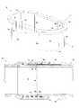
- FIG. 1is an exploded perspective view of the preferred embodiment of the disconnection tool of the present invention showing a first part of the disconnection tool separated from a second part of the disconnection tool.
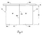
- FIG. 2is a side view of the preferred embodiment of the present invention with the first part of the disconnection tool converged with the second part of the disconnection tool.
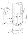
- FIG. 3is an exploded perspective view of the disconnection tool of the present invention being positioned around a male end of a male pipe which is inserted into a female end of a female pipe.
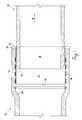
- FIG. 4is a cross sectional side view of the preferred embodiment of the present invention taken along the male end of the male pipe and the female end of the female pipe prior to insertion of the disconnection tool into a clearance between the male end and the female end.
- FIG. 5is a cross sectional side view of the preferred embodiment of the present invention taken along the male end of the male pipe and the female end of the female pipe, with the disconnection tool being inserted into a clearance between the male end and the female end and engaging the rigid fingers within the clearance.
- FIG. 6is the same view as depicted in FIG. 4 , with the disconnection tool being fully inserted into the clearance between the male end of the male pipe and the female end of the female pipe.
- FIG. 7is the same view as depicted in FIG. 5 , with the male end of the male pipe being withdrawn from the female end of the female pipe.
- the preferred embodiment of the pipe disconnection toolis shown in an exploded perspective view and front view respectively.
- the preferred embodiment of the disconnection toolhas a first part 10 and a second part 12 which, when converged together, form the preferred embodiment of the disconnection tool.
- both the first part 10 and the second part 12have identical structure with semicircular cross sections. Therefore, in the preferred embodiment a description of structure that is present for the first part 10 in the Figures applies equally to a description of the structure for the second part 12 , and vice versa.
- the disconnection tool of the present inventionhas an insertion member 16 comprised of a first insertion member 16 a of the first part 10 and a second insertion member 16 b of the second part 12 .
- Each insertion member 16 a , 16 bis formed by inner walls 26 and outer walls 30 .
- each insertion member 16 a , 16 bis semi-cylindrically shaped such that it can be positioned around and adjacent to an exterior surface 28 of a male end 18 of a male pipe 32 .
- the inner walls 26 of the insertion members 16 a , 16 bare concavely contoured to fit adjacent to and around at least a portion of the convex exterior surface 28 of the male end 18 of the male pipe 32 .
- the exterior surface 28 of the male end 18 of the male pipe 32is the radially outermost exterior surface of the male end 18 .
- the first part 10 and the second part 12are converged such that first and second sidewalls 34 a , 34 b of the first part 10 align with and abut corresponding first and second sidewalls 40 a , 40 b of the second part 12 , thereby forming a cylindrical insertion member 16 .
- the insertion member 16could be adapted to form a cylindrical insertion member 16 in other manners.
- the insertion member 16could be formed of one continuous cylinder.
- both the first part 10 and the second part 12 of the disconnection toolhave handles 44 a , 44 b which extend from the first and second insertion members 16 a and 16 b respectively.
- each handle 44 a , 44 bis a semicircular flange that extends perpendicular from an end 46 of the insertion member 16 opposite a leading edge 50 of the insertion member 16 .
- the semi-circular length of the first handle 44 ahas ends which are adjacent and aligned with the first and second sidewalls 34 a , 34 b of the first part 10 .
- the semi-circular length of the second handle 44 bhas ends which are adjacent and aligned with the first and second sidewalls 40 a , 40 b of the second part 12 .
- the ends of each handle 44 a , 44 balso converge, thereby forming a circular flange around the cylindrical insertion member 16 .
- each handle 44 a , 44 bmay have alternative shapes and sizes and still operate in a manner consistent with this invention. It can also be understood that in an embodiment where the insertion member 16 is one continuous cylinder, the handle 44 may be one continuous flange.
- the leading edge 50 of the insertion member 16is at the end of the insertion member 16 nearest a female end 14 of a female pipe 52 when the insertion member 16 is positioned around the male end 18 of the male pipe 32 , prior to insertion of the insertion member 16 (see FIG. 4 ).
- the leading edge 50 of the insertion member 16lies in a plane that is perpendicular to the longitudinal axis of the male and female pipes 32 , 52 .
- the longitudinal directionis along the axis of the male and female pipes 32 , 52 and the axis of the cylindrical or semi-cylindrical insertion member 16 .
- the insertion member 16has a thickness that is equal to or less than a clearance 54 between the exterior surface 28 of the male end 18 of the male pipe 32 and an interior surface 20 of the female end 14 of the female pipe 52 when the pipes 32 , 52 are connected (see FIG. 3 ).
- the interior surface 20 of the female end 14 of the female pipe 52defines a male end receiving chamber (not shown), which is essentially the interior space within the female end 14 .
- the interior surface 20 of the female end 14 of the female pipe 52is the radially innermost interior surface of the female end 14 .
- the exterior surface 28 of the male end 18has an outer diameter less than the diameter of the male end receiving chamber and the clearance 54 is present in the male end receiving chamber between the exterior surface 28 of the male end 18 of the male pipe 32 and the interior surface 20 of the female end 14 of the female pipe 52 .
- the clearance 54is approximately 0.0525 inches.
- FIG. 4shows the preferred embodiment prior to insertion of the insertion member 16 .
- a plurality of sets 56 a, b, c, d of rigid fingers 38extend from interior circumferential grooves 36 a, b, c, d on the interior surface 20 of the female end 14 of the female pipe 52 into the male end receiving chamber, across the clearance 54 , and into corresponding exterior circumferential grooves 42 a, b, c, d on the exterior surface 28 of the male end 18 of the male pipe 32 .
- FIG. 5a cross section of the male end 18 of the male pipe 32 connected to the female end 14 of the female pipe 52 is shown with a portion of the insertion member 16 inserted into the clearance 54 .
- Insertion member 16is inserted into the clearance 54 by moving the insertion member 16 with a force f toward the female pipe 52 .
- Force fcauses longitudinal movement of the insertion member 16 along the exterior surface 28 of the male end 18 of the male pipe 32 .
- force fis a force parallel to the male pipe 32 and is applied to each handle 44 a , 44 b of the disconnection tool.
- the disconnection tooldisplaces the rigid fingers 38 from each of the sets 56 a, b, c, d from the exterior circumferential grooves 42 a, b, c, d on the exterior surface 28 of the male end 14 of the male pipe 32 .
- FIG. 5shows the leading edge 50 of the insertion member 16 engaging the second set 56 b of rigid fingers 38 and displacing the rigid fingers 38 from the corresponding exterior circumferential groove 42 b on the male end 14 of the male pipe 32 .
- a distal end 48 of each of the rigid fingers 38is displaced out of the corresponding exterior circumferential groove 42 b .
- the leading edge 50 of the insertion member 16already has passed over and displaced the first set 56 a of rigid fingers 38 in the same manner as described with regard to the second set 56 b of rigid fingers 38 .
- the outer walls 30 of the insertion member 16hold the distal end 48 of each of the rigid fingers 38 out of the corresponding exterior circumferential grooves 42 a, b, c, b on the male end 18 of the male pipe 32 .
- the insertion member 16should be made of a rigid material to displace and hold the rigid fingers 38 .
- the handle 44is also preferably made from a rigid material. In the preferred embodiment both the insertion member 16 and the handle 44 are made from stainless steel.
- each handle 44 a , 44 babuts a leading edge 22 of the female end 14 and acts as a stop to keep the insertion member 16 from being further inserted into the clearance 54 .
- each handle 44 a , 44 bis five inches away from the leading edge 50 of the insertion member 16 .
- leading edge 50 of the insertion member 16may abut a shoulder 58 within the female end 14 , or, a stop member (not shown) may be disposed on the insertion member 16 and abut the female leading edge 22 of the female pipe 52 , to stop further insertion of the insertion member 16 .
- the insertion member 16has an insertion length 60 which is the length of the portion of the insertion member 16 that is positioned in the clearance 54 when the insertion member 16 is fully inserted (see FIG. 2 ).
- the insertion length 60is long enough for outer walls 30 of the insertion member 16 to displace and hold the distal end 48 of all the rigid fingers 38 out of their corresponding exterior circumferential groove on the male end 18 of the male pipe 32 .
- the insertion length 60could be just long enough so the leading edge 50 of the insertion member 16 holds the distal end 48 of the last set of rigid fingers 38 out of their corresponding exterior circumferential groove on the male end 18 .
- each handle 44 a , 44 bis positioned such that the longitudinal distance from the leading edge 50 of the insertion member 16 to each handle 44 a , 44 b is greater or equal to the insertion length 60 of the insertion member 16 .
- the insertion length 60is preferably five inches long.
- the male end 18 of the male pipe 32can now be withdrawn from the female end 14 of the female pipe 52 .
- the male pipe 32is pulled from within the male end receiving chamber and insertion member 16 in the direction d shown in FIG. 7 .
- the insertion member 16is removed from the female end 14 of the female pipe 52 .
Landscapes
- Engineering & Computer Science (AREA)
- General Engineering & Computer Science (AREA)
- Mechanical Engineering (AREA)
- Quick-Acting Or Multi-Walled Pipe Joints (AREA)
- Hand Tools For Fitting Together And Separating, Or Other Hand Tools (AREA)
Abstract
Description
Claims (44)
Priority Applications (1)
| Application Number | Priority Date | Filing Date | Title |
|---|---|---|---|
| US12/891,544US8814219B2 (en) | 2009-02-03 | 2010-09-27 | Push lock pipe connection system and disconnection tool |
Applications Claiming Priority (2)
| Application Number | Priority Date | Filing Date | Title |
|---|---|---|---|
| US12/365,000US8342579B2 (en) | 2009-02-03 | 2009-02-03 | Push lock pipe connection system |
| US12/891,544US8814219B2 (en) | 2009-02-03 | 2010-09-27 | Push lock pipe connection system and disconnection tool |
Related Parent Applications (1)
| Application Number | Title | Priority Date | Filing Date |
|---|---|---|---|
| US12/365,000Continuation-In-PartUS8342579B2 (en) | 2009-02-03 | 2009-02-03 | Push lock pipe connection system |
Publications (2)
| Publication Number | Publication Date |
|---|---|
| US20110012339A1 US20110012339A1 (en) | 2011-01-20 |
| US8814219B2true US8814219B2 (en) | 2014-08-26 |
Family
ID=43464726
Family Applications (1)
| Application Number | Title | Priority Date | Filing Date |
|---|---|---|---|
| US12/891,544Active2029-08-23US8814219B2 (en) | 2009-02-03 | 2010-09-27 | Push lock pipe connection system and disconnection tool |
Country Status (1)
| Country | Link |
|---|---|
| US (1) | US8814219B2 (en) |
Cited By (8)
| Publication number | Priority date | Publication date | Assignee | Title |
|---|---|---|---|---|
| US20150136408A1 (en)* | 2013-11-19 | 2015-05-21 | David Wright | Stab connector assembly and methods usable for establishing a fluid connection |
| US20150136423A1 (en)* | 2013-11-19 | 2015-05-21 | David C. Wright | Fluid connector assembly with automatic flow shut-off and method usable for establishing a fluid connection |
| US20170059041A1 (en)* | 2015-08-28 | 2017-03-02 | Doosan Infracore Co., Ltd. | Dust preventing seal and construction machine having the same |
| US9989075B2 (en) | 2012-09-19 | 2018-06-05 | Buemach Engineering International B.V. | Working cylinder |
| US10746335B2 (en) | 2017-02-14 | 2020-08-18 | North American Pipe Corporation | System, method and apparatus for ramped retainer for a pipe |
| US10962157B2 (en) | 2017-04-18 | 2021-03-30 | Cobalt Coupler Systems, LLC | Coupler |
| US11060646B2 (en) | 2017-04-18 | 2021-07-13 | Cobalt Coupler Systems, LLC | Coupler |
| US11560972B2 (en) | 2017-04-18 | 2023-01-24 | Cobalt Coupler Systems, LLC | Oil and gas pipe connector |
Families Citing this family (4)
| Publication number | Priority date | Publication date | Assignee | Title |
|---|---|---|---|---|
| US10221977B2 (en) | 2009-02-03 | 2019-03-05 | Aqseptence Group, Inc. | Pipe coupling |
| US9689517B2 (en)* | 2010-09-23 | 2017-06-27 | Republic Conduit, Inc. | Tool-free metal conduit connector and related methods |
| GB2555389B (en)* | 2016-10-21 | 2022-08-10 | Crane Ltd | Pipe coupling |
| US11506316B2 (en)* | 2017-03-06 | 2022-11-22 | Ipex Technologies Inc. | Releasable connect/disconnect fitting connection |
Citations (92)
| Publication number | Priority date | Publication date | Assignee | Title |
|---|---|---|---|---|
| US1587079A (en)* | 1923-08-15 | 1926-06-01 | Shuichi Katakura | Hose coupling |
| US2111956A (en)* | 1937-01-27 | 1938-03-22 | Eclipse Machine Co | Automatic coupling |
| US2479960A (en)* | 1946-01-10 | 1949-08-23 | Alden E Osborn | Pipe joint |
| US2785910A (en) | 1955-05-05 | 1957-03-19 | Amercoat Corp | Molded joint for plastic tubes with latch |
| US3272538A (en) | 1964-11-17 | 1966-09-13 | Union Carbide Corp | Restrained pipe joints |
| US3389923A (en) | 1967-11-08 | 1968-06-25 | Haveg Industries Inc | Joint connection |
| US3413021A (en) | 1965-10-20 | 1968-11-26 | Ferry Cap & Set Screw Co | Tubular coupling |
| US3534776A (en)* | 1968-06-10 | 1970-10-20 | Lafayette E Gilreath | Sealed pipe joint and releasing means therefor |
| US3744824A (en) | 1972-06-26 | 1973-07-10 | Graenges Essem Ab | Pipe couplings |
| US3784235A (en) | 1971-10-08 | 1974-01-08 | Us Navy | Tubular adhesive joint with snap lock |
| DE2440886A1 (en) | 1974-08-27 | 1976-03-25 | Toschi Gmbh & Co Kg | Connector for asbestos cement pressure pipes - has V-cross section hard rubber holding ring that locates in pipe recess |
| US3995897A (en) | 1975-04-21 | 1976-12-07 | Eaton Corporation | Coupling |
| US4030850A (en) | 1976-08-02 | 1977-06-21 | The United States Of America As Represented By The Secretary Of The Army | Interlocked joint |
| US4072328A (en) | 1976-05-25 | 1978-02-07 | Hepworth Plastics Limited | Pipe couplings |
| US4105226A (en) | 1976-06-01 | 1978-08-08 | Celanese Corporation | Snap-in fittings and coupling ring therefor |
| US4128264A (en) | 1977-01-21 | 1978-12-05 | Huron Tool & Manufacturing Division Of U.S. Industries, Inc. | Two-piece fitting assembly |
| US4191384A (en)* | 1977-04-12 | 1980-03-04 | Forsheda Gummifabrik Ab | Method and device for sealing a pipe joint |
| GB1584085A (en) | 1977-01-28 | 1981-02-04 | Celanese Corp | Coupling ring for use in snap-on fitting |
| US4276010A (en) | 1979-03-23 | 1981-06-30 | Plastic Machinery Corporation | Pipe beller with force determined temperature |
| US4471978A (en)* | 1978-06-07 | 1984-09-18 | Dieter Kramer | Push-pull connecting system for pressure lines, brake-system lines in particular |
| US4490576A (en) | 1981-08-10 | 1984-12-25 | Appleton Electric Co. | Connector for use with jacketed metal clad cable |
| US4508369A (en)* | 1978-06-02 | 1985-04-02 | Nycoil Corporation | Releasable coupling device |
| US4600223A (en) | 1982-09-21 | 1986-07-15 | Vries Robert De | Tube coupling |
| US4749214A (en)* | 1985-09-17 | 1988-06-07 | John T. Hoskins | Quick connect fluid coupling |
| US4779902A (en) | 1987-07-06 | 1988-10-25 | Mid-Continent Pipe & Supply Co., Inc. | Plastic pipe with integral end connection |
| US4781400A (en)* | 1987-07-01 | 1988-11-01 | General Motors Corporation | Quick connect tube coupling |
| US4854397A (en) | 1988-09-15 | 1989-08-08 | Amoco Corporation | System for directional drilling and related method of use |
| US4875713A (en) | 1985-09-24 | 1989-10-24 | Kenneth J. Carstensen | Internally coated tubular system |
| US4927185A (en)* | 1989-03-07 | 1990-05-22 | Huron Products Corporation | Release tool for fluid quick connectors |
| US4979765A (en)* | 1980-10-29 | 1990-12-25 | Proprietary Technology, Inc. | Swivelable quick connector assembly |
| US5005877A (en)* | 1988-12-16 | 1991-04-09 | Parker Hannifin Corporation | Quick connect/disconnect fluid coupling |
| US5015014A (en) | 1989-06-19 | 1991-05-14 | Aardvark Corporation, Inc. | Plastic pipe section |
| US5119892A (en) | 1989-11-25 | 1992-06-09 | Reed Tool Company Limited | Notary drill bits |
| US5219188A (en)* | 1991-01-09 | 1993-06-15 | Sanoh Kogyo Kabushiki Kaisha | Construction for preventing incomplete connection of pipes |
| US5251942A (en) | 1992-03-05 | 1993-10-12 | Whaley Kent R | Self-sealing pipe thread |
| US5378024A (en)* | 1992-03-25 | 1995-01-03 | Tokai Rubber Industries, Ltd. | Quick connector |
| EP0664405A1 (en) | 1994-01-19 | 1995-07-26 | John Derek Guest | Improvements in or relating to grab rings |
| US5533761A (en)* | 1994-10-26 | 1996-07-09 | Itt Corporation | Quick connector release member |
| US5542717A (en) | 1994-01-03 | 1996-08-06 | Form Rite, Corporation | Quick connect coupling |
| US5580100A (en)* | 1994-02-25 | 1996-12-03 | Usui Kokusai Sangyo Kaisha Ltd. | Connecting joint for plastic tube |
| US5584512A (en) | 1993-10-07 | 1996-12-17 | Carstensen; Kenneth J. | Tubing interconnection system with different size snap ring grooves |
| US5662360A (en) | 1996-01-05 | 1997-09-02 | S&B Technical Products, Inc. | Interlocked restraint for a plastic pipe joining system |
| US5685575A (en)* | 1995-11-03 | 1997-11-11 | Aeroquip Corporation | Power steering coupling assembly |
| CH688659A5 (en) | 1993-05-27 | 1997-12-31 | Alphacan Somo | Plastic pipe, especially e.g. for use in relining drains |
| US5716081A (en) | 1996-03-11 | 1998-02-10 | Automotive Products (Usa), Inc. | Spring clip for quick connect coupling |
| US5738388A (en) | 1994-03-15 | 1998-04-14 | Atlas Copco Craelius Ab | Device for permanent joining of tubes |
| US5826921A (en) | 1991-11-25 | 1998-10-27 | Woolley; Brown J. | Threaded pipe joint |
| US5845945A (en) | 1993-10-07 | 1998-12-08 | Carstensen; Kenneth J. | Tubing interconnection system with different size snap ring grooves |
| US5909901A (en)* | 1998-02-22 | 1999-06-08 | Jiffy-Tite Company, Inc. | Disconnect tool for a fluid line quick-connect assembly |
| US5918914A (en) | 1997-11-25 | 1999-07-06 | Morris; Waldo Ivan | Sealing lock joint pipe fitting |
| US5934709A (en)* | 1994-03-11 | 1999-08-10 | Australasian Steel Products Pty Ltd. | Fluid couplings |
| US5971445A (en) | 1997-11-10 | 1999-10-26 | Pilot Industries, Inc. | Quick connect coupling with improved retainer |
| US5975591A (en) | 1996-07-17 | 1999-11-02 | Guest; John Derek | Coupling bodies |
| US5988705A (en) | 1993-05-24 | 1999-11-23 | Pilot Industries, Inc. | Quick connect coupling |
| US5988704A (en) | 1996-01-02 | 1999-11-23 | Aba Of Sweden Ab | Hose coupling device |
| US6062326A (en) | 1995-03-11 | 2000-05-16 | Enterprise Oil Plc | Casing shoe with cutting means |
| WO2000057096A1 (en) | 1999-03-18 | 2000-09-28 | Techmo Entwicklungs- Und Vertriebs Gmbh | Pipe connector |
| US6152496A (en) | 1997-11-14 | 2000-11-28 | Nitto Kohki Co., Ltd. | Socket for pipe coupling |
| US6176523B1 (en) | 1997-03-12 | 2001-01-23 | The Lamson & Sessions Co. | Joint for variable wall thickness conduit |
| US6325424B1 (en) | 1998-01-12 | 2001-12-04 | The Lamson & Sessions Co. | Coupling assembly having enhanced axial tension strength |
| FR2810087A1 (en) | 2000-06-08 | 2001-12-14 | Legris Sa | Insert for implanting pipe connection in tapped housing comprises body which fits against tapped section, on which rings with anchor lugs are mounted, each lug being compressible from position above outer surface of insert to below it |
| US6343814B1 (en)* | 1999-11-08 | 2002-02-05 | Ti Group Automotive Systems, Llc | Insertion verifier dust cap |
| US6401820B1 (en) | 1998-01-24 | 2002-06-11 | Downhole Products Plc | Downhole tool |
| US6464024B2 (en) | 1999-06-30 | 2002-10-15 | Smith International, Inc. | Bi-centered drill bit having improved drilling stability, mud hydraulics and resistance to cutter damage |
| US6499771B1 (en) | 2000-07-18 | 2002-12-31 | Victaulic Company Of America | Mechanical pipe coupling with toothed retainer |
| US6568658B2 (en) | 2000-12-22 | 2003-05-27 | Craneveyor Corporation | Quick-connect railing connector |
| US20030116960A1 (en)* | 2001-07-06 | 2003-06-26 | Yates Ronnie A. | Flexible tubing connector |
| US20030122372A1 (en)* | 2001-12-28 | 2003-07-03 | Smc Kabushiki Kaisha | Tube joint |
| US6666480B2 (en) | 2001-11-20 | 2003-12-23 | Modern Products Industries, Inc. | Submersible pump drop pipe and casing assembly connection and method of manufacture |
| US6688655B1 (en)* | 2000-08-24 | 2004-02-10 | Yokohama Hydex Co., Ltd. | Quick connection-release coupling |
| US20040070198A1 (en)* | 2001-12-20 | 2004-04-15 | Harald Rohrig | Connection piece for fluid lines and device embedded thereas |
| WO2004104365A1 (en) | 2003-05-20 | 2004-12-02 | Fmc Technologies, Inc. | Low profile connector |
| US20040245766A1 (en)* | 2001-09-21 | 2004-12-09 | Christophe Vallee | Quick coupling device |
| US6964435B2 (en) | 2002-02-18 | 2005-11-15 | Walterscheid Rohrverbindungstechnik Gmbh | Coupling for connecting hydraulic ducts |
| US6988747B2 (en) | 2003-03-20 | 2006-01-24 | Rain Bird Corporation | Multi-diameter tube coupling |
| US7029035B2 (en) | 2003-09-11 | 2006-04-18 | International Engine Intellectual Property Company, Llc | Release collar for coupling assembly |
| EP1669655A1 (en) | 2004-12-09 | 2006-06-14 | Itt Manufacturing Enterprises, Inc. | Fluid coupling with dual function retention ring |
| US7097211B2 (en)* | 2001-11-09 | 2006-08-29 | Adams Robert M | Pipe coupling system having an anti-reversing locking ring |
| EP1703191A2 (en) | 2005-03-17 | 2006-09-20 | TECE GmbH & Co. KG | Conduit coupling |
| US20060214422A1 (en) | 2005-03-28 | 2006-09-28 | Victaulic Company Fo America | Pipe coupling retainer with axial support members |
| US20070001450A1 (en)* | 2005-03-11 | 2007-01-04 | Swift Jonathan C | Pressure activated disconnect lock coupling |
| US7264281B2 (en)* | 2002-09-05 | 2007-09-04 | Legris Sa | Connection means for high pressure fluid ducts |
| EP1933074A2 (en) | 2006-12-12 | 2008-06-18 | John Guest International Limited | Improvements in or relating to tube couplings |
| US7445250B2 (en)* | 2004-09-17 | 2008-11-04 | The Gates Corporation | Quick connect coupling |
| US7445247B2 (en)* | 2003-05-29 | 2008-11-04 | Orbit Irrigation Products, Inc. | Irrigation coupling apparatus |
| US7455328B2 (en) | 2003-09-25 | 2008-11-25 | David Chelchowski | Collet for pipe coupling |
| US7469933B2 (en)* | 2005-03-11 | 2008-12-30 | The Gates Corporation | Quick connect coupling with disconnect lock |
| US7523966B2 (en) | 1998-12-18 | 2009-04-28 | Accor Technology, Inc. | Tube coupling |
| US20090278347A1 (en)* | 2008-05-08 | 2009-11-12 | Jim Kerin | Quick connector, release tool, and method therefor |
| US7832774B2 (en)* | 2002-06-14 | 2010-11-16 | Eaton Corporation | Coupling assembly |
| US7841630B1 (en) | 2007-09-19 | 2010-11-30 | Bridgeport Fittings, Inc. | Electric metal tube push-in fitting |
| US7963570B2 (en)* | 2005-09-01 | 2011-06-21 | The Gates Corporation | Quick connect coupling stabilization apparatus, systems and methods |
- 2010
- 2010-09-27USUS12/891,544patent/US8814219B2/enactiveActive
Patent Citations (99)
| Publication number | Priority date | Publication date | Assignee | Title |
|---|---|---|---|---|
| US1587079A (en)* | 1923-08-15 | 1926-06-01 | Shuichi Katakura | Hose coupling |
| US2111956A (en)* | 1937-01-27 | 1938-03-22 | Eclipse Machine Co | Automatic coupling |
| US2479960A (en)* | 1946-01-10 | 1949-08-23 | Alden E Osborn | Pipe joint |
| US2785910A (en) | 1955-05-05 | 1957-03-19 | Amercoat Corp | Molded joint for plastic tubes with latch |
| US3272538A (en) | 1964-11-17 | 1966-09-13 | Union Carbide Corp | Restrained pipe joints |
| US3413021A (en) | 1965-10-20 | 1968-11-26 | Ferry Cap & Set Screw Co | Tubular coupling |
| US3389923A (en) | 1967-11-08 | 1968-06-25 | Haveg Industries Inc | Joint connection |
| US3534776A (en)* | 1968-06-10 | 1970-10-20 | Lafayette E Gilreath | Sealed pipe joint and releasing means therefor |
| US3784235A (en) | 1971-10-08 | 1974-01-08 | Us Navy | Tubular adhesive joint with snap lock |
| US3744824A (en) | 1972-06-26 | 1973-07-10 | Graenges Essem Ab | Pipe couplings |
| DE2440886A1 (en) | 1974-08-27 | 1976-03-25 | Toschi Gmbh & Co Kg | Connector for asbestos cement pressure pipes - has V-cross section hard rubber holding ring that locates in pipe recess |
| US3995897A (en) | 1975-04-21 | 1976-12-07 | Eaton Corporation | Coupling |
| US4072328A (en) | 1976-05-25 | 1978-02-07 | Hepworth Plastics Limited | Pipe couplings |
| US4105226A (en) | 1976-06-01 | 1978-08-08 | Celanese Corporation | Snap-in fittings and coupling ring therefor |
| US4030850A (en) | 1976-08-02 | 1977-06-21 | The United States Of America As Represented By The Secretary Of The Army | Interlocked joint |
| US4128264A (en) | 1977-01-21 | 1978-12-05 | Huron Tool & Manufacturing Division Of U.S. Industries, Inc. | Two-piece fitting assembly |
| GB1584085A (en) | 1977-01-28 | 1981-02-04 | Celanese Corp | Coupling ring for use in snap-on fitting |
| US4191384A (en)* | 1977-04-12 | 1980-03-04 | Forsheda Gummifabrik Ab | Method and device for sealing a pipe joint |
| US4508369A (en)* | 1978-06-02 | 1985-04-02 | Nycoil Corporation | Releasable coupling device |
| US4471978A (en)* | 1978-06-07 | 1984-09-18 | Dieter Kramer | Push-pull connecting system for pressure lines, brake-system lines in particular |
| US4276010A (en) | 1979-03-23 | 1981-06-30 | Plastic Machinery Corporation | Pipe beller with force determined temperature |
| US4979765A (en)* | 1980-10-29 | 1990-12-25 | Proprietary Technology, Inc. | Swivelable quick connector assembly |
| US4490576A (en) | 1981-08-10 | 1984-12-25 | Appleton Electric Co. | Connector for use with jacketed metal clad cable |
| US4600223A (en) | 1982-09-21 | 1986-07-15 | Vries Robert De | Tube coupling |
| US4749214A (en)* | 1985-09-17 | 1988-06-07 | John T. Hoskins | Quick connect fluid coupling |
| US4875713A (en) | 1985-09-24 | 1989-10-24 | Kenneth J. Carstensen | Internally coated tubular system |
| US4781400A (en)* | 1987-07-01 | 1988-11-01 | General Motors Corporation | Quick connect tube coupling |
| US4779902A (en) | 1987-07-06 | 1988-10-25 | Mid-Continent Pipe & Supply Co., Inc. | Plastic pipe with integral end connection |
| US4875714A (en) | 1987-07-06 | 1989-10-24 | Mid-Continent Pipe & Supply Company, Inc. | Plastic pipe with locking integral end connection |
| US4854397A (en) | 1988-09-15 | 1989-08-08 | Amoco Corporation | System for directional drilling and related method of use |
| US5005877A (en)* | 1988-12-16 | 1991-04-09 | Parker Hannifin Corporation | Quick connect/disconnect fluid coupling |
| US4927185A (en)* | 1989-03-07 | 1990-05-22 | Huron Products Corporation | Release tool for fluid quick connectors |
| US5015014A (en) | 1989-06-19 | 1991-05-14 | Aardvark Corporation, Inc. | Plastic pipe section |
| US5119892A (en) | 1989-11-25 | 1992-06-09 | Reed Tool Company Limited | Notary drill bits |
| US5219188A (en)* | 1991-01-09 | 1993-06-15 | Sanoh Kogyo Kabushiki Kaisha | Construction for preventing incomplete connection of pipes |
| US5826921A (en) | 1991-11-25 | 1998-10-27 | Woolley; Brown J. | Threaded pipe joint |
| US5251942A (en) | 1992-03-05 | 1993-10-12 | Whaley Kent R | Self-sealing pipe thread |
| US5378024A (en)* | 1992-03-25 | 1995-01-03 | Tokai Rubber Industries, Ltd. | Quick connector |
| US5988705A (en) | 1993-05-24 | 1999-11-23 | Pilot Industries, Inc. | Quick connect coupling |
| CH688659A5 (en) | 1993-05-27 | 1997-12-31 | Alphacan Somo | Plastic pipe, especially e.g. for use in relining drains |
| US5845945A (en) | 1993-10-07 | 1998-12-08 | Carstensen; Kenneth J. | Tubing interconnection system with different size snap ring grooves |
| US5584512A (en) | 1993-10-07 | 1996-12-17 | Carstensen; Kenneth J. | Tubing interconnection system with different size snap ring grooves |
| US5542717A (en) | 1994-01-03 | 1996-08-06 | Form Rite, Corporation | Quick connect coupling |
| EP0664405A1 (en) | 1994-01-19 | 1995-07-26 | John Derek Guest | Improvements in or relating to grab rings |
| US5580100A (en)* | 1994-02-25 | 1996-12-03 | Usui Kokusai Sangyo Kaisha Ltd. | Connecting joint for plastic tube |
| US5934709A (en)* | 1994-03-11 | 1999-08-10 | Australasian Steel Products Pty Ltd. | Fluid couplings |
| US5738388A (en) | 1994-03-15 | 1998-04-14 | Atlas Copco Craelius Ab | Device for permanent joining of tubes |
| US5533761A (en)* | 1994-10-26 | 1996-07-09 | Itt Corporation | Quick connector release member |
| US6062326A (en) | 1995-03-11 | 2000-05-16 | Enterprise Oil Plc | Casing shoe with cutting means |
| US5685575A (en)* | 1995-11-03 | 1997-11-11 | Aeroquip Corporation | Power steering coupling assembly |
| US5988704A (en) | 1996-01-02 | 1999-11-23 | Aba Of Sweden Ab | Hose coupling device |
| US5662360A (en) | 1996-01-05 | 1997-09-02 | S&B Technical Products, Inc. | Interlocked restraint for a plastic pipe joining system |
| US5716081A (en) | 1996-03-11 | 1998-02-10 | Automotive Products (Usa), Inc. | Spring clip for quick connect coupling |
| US5975591A (en) | 1996-07-17 | 1999-11-02 | Guest; John Derek | Coupling bodies |
| US6176523B1 (en) | 1997-03-12 | 2001-01-23 | The Lamson & Sessions Co. | Joint for variable wall thickness conduit |
| US5971445A (en) | 1997-11-10 | 1999-10-26 | Pilot Industries, Inc. | Quick connect coupling with improved retainer |
| US6152496A (en) | 1997-11-14 | 2000-11-28 | Nitto Kohki Co., Ltd. | Socket for pipe coupling |
| US5918914A (en) | 1997-11-25 | 1999-07-06 | Morris; Waldo Ivan | Sealing lock joint pipe fitting |
| US6325424B1 (en) | 1998-01-12 | 2001-12-04 | The Lamson & Sessions Co. | Coupling assembly having enhanced axial tension strength |
| US6401820B1 (en) | 1998-01-24 | 2002-06-11 | Downhole Products Plc | Downhole tool |
| US5909901A (en)* | 1998-02-22 | 1999-06-08 | Jiffy-Tite Company, Inc. | Disconnect tool for a fluid line quick-connect assembly |
| US7523966B2 (en) | 1998-12-18 | 2009-04-28 | Accor Technology, Inc. | Tube coupling |
| US7810850B2 (en) | 1998-12-18 | 2010-10-12 | Accor Technology, Inc. | Tube coupling |
| WO2000057096A1 (en) | 1999-03-18 | 2000-09-28 | Techmo Entwicklungs- Und Vertriebs Gmbh | Pipe connector |
| US6464024B2 (en) | 1999-06-30 | 2002-10-15 | Smith International, Inc. | Bi-centered drill bit having improved drilling stability, mud hydraulics and resistance to cutter damage |
| US20030094813A1 (en)* | 1999-11-08 | 2003-05-22 | Ti Group Automotive Systems Corporation | Insertion verifier dust cap |
| US6343814B1 (en)* | 1999-11-08 | 2002-02-05 | Ti Group Automotive Systems, Llc | Insertion verifier dust cap |
| FR2810087A1 (en) | 2000-06-08 | 2001-12-14 | Legris Sa | Insert for implanting pipe connection in tapped housing comprises body which fits against tapped section, on which rings with anchor lugs are mounted, each lug being compressible from position above outer surface of insert to below it |
| US6499771B1 (en) | 2000-07-18 | 2002-12-31 | Victaulic Company Of America | Mechanical pipe coupling with toothed retainer |
| US6688655B1 (en)* | 2000-08-24 | 2004-02-10 | Yokohama Hydex Co., Ltd. | Quick connection-release coupling |
| US6568658B2 (en) | 2000-12-22 | 2003-05-27 | Craneveyor Corporation | Quick-connect railing connector |
| US20030116960A1 (en)* | 2001-07-06 | 2003-06-26 | Yates Ronnie A. | Flexible tubing connector |
| US20040245766A1 (en)* | 2001-09-21 | 2004-12-09 | Christophe Vallee | Quick coupling device |
| US7097211B2 (en)* | 2001-11-09 | 2006-08-29 | Adams Robert M | Pipe coupling system having an anti-reversing locking ring |
| US6666480B2 (en) | 2001-11-20 | 2003-12-23 | Modern Products Industries, Inc. | Submersible pump drop pipe and casing assembly connection and method of manufacture |
| US7470383B2 (en) | 2001-11-20 | 2008-12-30 | Johnson Screens, Inc. | Submersible pump drop pipe and casing assembly connection and method of manufacture |
| US7425024B2 (en) | 2001-11-20 | 2008-09-16 | Johnson Screens, Inc. | Submersible pump drop pipe and casing assembly connection and method of manufacture |
| US7261326B2 (en) | 2001-11-20 | 2007-08-28 | Johnson Screens, Inc. | Submersible pump drop pipe and casing assembly connection and method of manufacture |
| US20040070198A1 (en)* | 2001-12-20 | 2004-04-15 | Harald Rohrig | Connection piece for fluid lines and device embedded thereas |
| US20030122372A1 (en)* | 2001-12-28 | 2003-07-03 | Smc Kabushiki Kaisha | Tube joint |
| US6964435B2 (en) | 2002-02-18 | 2005-11-15 | Walterscheid Rohrverbindungstechnik Gmbh | Coupling for connecting hydraulic ducts |
| US7832774B2 (en)* | 2002-06-14 | 2010-11-16 | Eaton Corporation | Coupling assembly |
| US7264281B2 (en)* | 2002-09-05 | 2007-09-04 | Legris Sa | Connection means for high pressure fluid ducts |
| US6988747B2 (en) | 2003-03-20 | 2006-01-24 | Rain Bird Corporation | Multi-diameter tube coupling |
| WO2004104365A1 (en) | 2003-05-20 | 2004-12-02 | Fmc Technologies, Inc. | Low profile connector |
| US7445247B2 (en)* | 2003-05-29 | 2008-11-04 | Orbit Irrigation Products, Inc. | Irrigation coupling apparatus |
| US7029035B2 (en) | 2003-09-11 | 2006-04-18 | International Engine Intellectual Property Company, Llc | Release collar for coupling assembly |
| US7455328B2 (en) | 2003-09-25 | 2008-11-25 | David Chelchowski | Collet for pipe coupling |
| US7445250B2 (en)* | 2004-09-17 | 2008-11-04 | The Gates Corporation | Quick connect coupling |
| US7819438B2 (en)* | 2004-09-17 | 2010-10-26 | The Gates Corporation | Quick connect coupling |
| EP1669655A1 (en) | 2004-12-09 | 2006-06-14 | Itt Manufacturing Enterprises, Inc. | Fluid coupling with dual function retention ring |
| US20070001450A1 (en)* | 2005-03-11 | 2007-01-04 | Swift Jonathan C | Pressure activated disconnect lock coupling |
| US7469933B2 (en)* | 2005-03-11 | 2008-12-30 | The Gates Corporation | Quick connect coupling with disconnect lock |
| EP1703191A2 (en) | 2005-03-17 | 2006-09-20 | TECE GmbH & Co. KG | Conduit coupling |
| US20060214422A1 (en) | 2005-03-28 | 2006-09-28 | Victaulic Company Fo America | Pipe coupling retainer with axial support members |
| US7963570B2 (en)* | 2005-09-01 | 2011-06-21 | The Gates Corporation | Quick connect coupling stabilization apparatus, systems and methods |
| EP1933074A2 (en) | 2006-12-12 | 2008-06-18 | John Guest International Limited | Improvements in or relating to tube couplings |
| US7841630B1 (en) | 2007-09-19 | 2010-11-30 | Bridgeport Fittings, Inc. | Electric metal tube push-in fitting |
| US20090278347A1 (en)* | 2008-05-08 | 2009-11-12 | Jim Kerin | Quick connector, release tool, and method therefor |
Non-Patent Citations (14)
| Title |
|---|
| Certainteed Corporation, "Kwik-Set (R) Threaded Drop Pipe" brochure, p. 1, 2004, place of publication-unknown. |
| Certainteed Corporation, "Kwik-Set (R) Threaded Drop Pipe" brochure, p. 1, 2004, place of publication—unknown. |
| Eastern District of Pennsylvania, "Memorandum and Order" construing certain claim terms of U.S. Patent No. 6,666,480, {Doc. No. 75), pp. 1-19, May 2, 2005, Civil Action No. 03-CV-2131, Published on PACER (www.pacer.gov). |
| Eastern District of Pennsylvania, "Memorandum of Plaintiff Certainteed Corporation in Support of Motion for Summary Judgment of Invalidity of the Patent in Suit," {Doc. No. 92), pp. 4-7. 9-12, Sep. 19, 2005, Civil Action No. 03-CV-2131, published on PACER (www.pacer.gov). |
| Eastern District of Pennsylvania, Order construing term "predetermined interior diameter" of U.S. Patent No. 6,666,480, {Doc. No. 116), p. 1, Oct. 24, 2005, Civil Action No. 03-CV-2131, published on PACER (www.pacer.gov). |
| European Patent Office, European Application No. 10250178.0 Extended European Search Report dated Mar. 5, 2012, pp. 1-6. |
| European Patent Office, European Application No. 10250178.0 Office Action dated Jul. 30, 2013, pp. 1-4. |
| Marcel Decker, Inc., Thomas Sixsmith, "Handbook of Thermoplastic Piping System Design," pp. 137-141, 1997, ISBN No. 0-8247-9846-5. |
| Mid-Continent, "PVC Water Well Casings and Screens" brochure, pp. MP00014-MP00017, published Apr. 1975, place of publication-unknown. |
| Mid-Continent, "PVC Water Well Casings and Screens" brochure, pp. MP00014-MP00017, published Apr. 1975, place of publication—unknown. |
| Transcript of May 12, 2004 deposition of Certainteed Corportaion witness John Stott, pp. 120 and 209-214, Civil Action No. 03-CV-2131 in the Untied States District Court, Eastern District of Pennsylvania. |
| Transcript of Nov. 18, 2004 deposition of Norther Products witness Victor Weigel pp. 40-41, 85-91, Civil Action No. A3-04-18 in the North Dakota District Court, Southeastern Division. |
| VMT Fibreglass Industries, "Glasspoll Fibregrass Reinforced Plastic Pipers and Screens" brochure, pp. 1-4, Jan. 1998, place of publication-unknown. |
| VMT Fibreglass Industries, "Glasspoll Fibregrass Reinforced Plastic Pipers and Screens" brochure, pp. 1-4, Jan. 1998, place of publication—unknown. |
Cited By (14)
| Publication number | Priority date | Publication date | Assignee | Title |
|---|---|---|---|---|
| US9989075B2 (en) | 2012-09-19 | 2018-06-05 | Buemach Engineering International B.V. | Working cylinder |
| US20150136423A1 (en)* | 2013-11-19 | 2015-05-21 | David C. Wright | Fluid connector assembly with automatic flow shut-off and method usable for establishing a fluid connection |
| US9309739B2 (en)* | 2013-11-19 | 2016-04-12 | David Wright | Stab connector assembly and methods usable for establishing a fluid connection |
| US20150136408A1 (en)* | 2013-11-19 | 2015-05-21 | David Wright | Stab connector assembly and methods usable for establishing a fluid connection |
| US9732595B2 (en)* | 2013-11-19 | 2017-08-15 | Wright's Well Control Services, Llc | Fluid connector assembly with automatic flow shut-off and method usable for establishing a fluid connection |
| US10428951B2 (en)* | 2015-08-28 | 2019-10-01 | Doosan Infracore Co., Ltd. | Dust preventing seal and construction machine having the same |
| US20170059041A1 (en)* | 2015-08-28 | 2017-03-02 | Doosan Infracore Co., Ltd. | Dust preventing seal and construction machine having the same |
| US10746335B2 (en) | 2017-02-14 | 2020-08-18 | North American Pipe Corporation | System, method and apparatus for ramped retainer for a pipe |
| US11441714B2 (en) | 2017-02-14 | 2022-09-13 | North American Pipe Corporation | System, method and apparatus for ramped retainer for a pipe |
| US10962157B2 (en) | 2017-04-18 | 2021-03-30 | Cobalt Coupler Systems, LLC | Coupler |
| US11060646B2 (en) | 2017-04-18 | 2021-07-13 | Cobalt Coupler Systems, LLC | Coupler |
| US11560972B2 (en) | 2017-04-18 | 2023-01-24 | Cobalt Coupler Systems, LLC | Oil and gas pipe connector |
| US11668422B2 (en) | 2017-04-18 | 2023-06-06 | Cobalt Coupler Systems, LLC | Coupler |
| US12338919B2 (en) | 2017-04-18 | 2025-06-24 | Cobalt Coupler Systems, LLC | Oil and gas pipe connector |
Also Published As
| Publication number | Publication date |
|---|---|
| US20110012339A1 (en) | 2011-01-20 |
Similar Documents
| Publication | Publication Date | Title |
|---|---|---|
| US8814219B2 (en) | Push lock pipe connection system and disconnection tool | |
| EP2213928B1 (en) | Push lock pipe connection system | |
| US9314098B2 (en) | Shelving connector | |
| US6824170B2 (en) | Self-locking coupling device | |
| KR102072842B1 (en) | Improvement in or relating to tube couplings | |
| US6371531B1 (en) | Stab-type coupling with collet having locking ribs and rotation prevention member | |
| US20100078934A1 (en) | Connector | |
| US9022432B2 (en) | Apparatus and method of coupling electrical conduit | |
| WO2013056273A2 (en) | Push-fit fitting with grip nut for pipes | |
| CN106537706A (en) | Integrated pipeline and method with adapter device | |
| WO2007052526A1 (en) | Assembly of male and female members | |
| US10030799B2 (en) | Pipe joint | |
| CN101044349B (en) | Segmented locking ring and corresponding assembly and installation method | |
| WO2009108963A2 (en) | Pipe fitting | |
| JP4932633B2 (en) | Water pipe connection device | |
| JP6000141B2 (en) | Pipe fitting and its socket | |
| JP4216672B2 (en) | Stop ring and fluid equipment with stop ring | |
| JP2009138869A (en) | Pipe joint connection component and piping structure | |
| JP6377493B2 (en) | Pipe joint connection structure | |
| JP4553478B2 (en) | Pipe connection structure | |
| JP4587547B2 (en) | Connection remover | |
| US11022245B2 (en) | Pipe hot-tapping system and method | |
| KR200283832Y1 (en) | piping coupler | |
| TW202331132A (en) | Pipe joint and pipe joining method | |
| GB2631788A (en) | A tube connector |
Legal Events
| Date | Code | Title | Description |
|---|---|---|---|
| AS | Assignment | Owner name:JOHNSON SCREENS, INC., TEXAS Free format text:ASSIGNMENT OF ASSIGNORS INTEREST;ASSIGNOR:BRABEC, DEAN;REEL/FRAME:025331/0206 Effective date:20101105 Owner name:JOHNSON SCREENS, INC., TEXAS Free format text:ASSIGNMENT OF ASSIGNORS INTEREST;ASSIGNOR:SAUL, GARTH;REEL/FRAME:025330/0844 Effective date:20101022 Owner name:JOHNSON SCREENS, INC., TEXAS Free format text:ASSIGNMENT OF ASSIGNORS INTEREST;ASSIGNOR:HENNEMANN, THOMAS L;REEL/FRAME:025329/0319 Effective date:20101025 | |
| AS | Assignment | Owner name:BILFINGER WATER TECHNOLOGIES INC., MINNESOTA Free format text:CHANGE OF NAME;ASSIGNOR:JOHNSON SCREENS, INC.;REEL/FRAME:033340/0038 Effective date:20130605 Owner name:BILFINGER WATER TECHNOLOGIES, INC., MINNESOTA Free format text:CHANGE OF NAME;ASSIGNOR:BILFINGER WATER TECHNOLOGIES INC.;REEL/FRAME:033340/0198 Effective date:20130801 | |
| STCF | Information on status: patent grant | Free format text:PATENTED CASE | |
| MAFP | Maintenance fee payment | Free format text:PAYMENT OF MAINTENANCE FEE, 4TH YEAR, LARGE ENTITY (ORIGINAL EVENT CODE: M1551) Year of fee payment:4 | |
| MAFP | Maintenance fee payment | Free format text:PAYMENT OF MAINTENANCE FEE, 8TH YEAR, LARGE ENTITY (ORIGINAL EVENT CODE: M1552); ENTITY STATUS OF PATENT OWNER: LARGE ENTITY Year of fee payment:8 |