US8814019B2 - Reconfigurable electrical wired cumberbund - Google Patents
Reconfigurable electrical wired cumberbundDownload PDFInfo
- Publication number
- US8814019B2 US8814019B2US13/190,588US201113190588AUS8814019B2US 8814019 B2US8814019 B2US 8814019B2US 201113190588 AUS201113190588 AUS 201113190588AUS 8814019 B2US8814019 B2US 8814019B2
- Authority
- US
- United States
- Prior art keywords
- cumberbund
- web
- layers
- garment
- passageway
- Prior art date
- Legal status (The legal status is an assumption and is not a legal conclusion. Google has not performed a legal analysis and makes no representation as to the accuracy of the status listed.)
- Active, expires
Links
Images


Classifications
- A—HUMAN NECESSITIES
- A41—WEARING APPAREL
- A41F—GARMENT FASTENINGS; SUSPENDERS
- A41F19/00—Garment suspenders not otherwise provided for
- A—HUMAN NECESSITIES
- A41—WEARING APPAREL
- A41D—OUTERWEAR; PROTECTIVE GARMENTS; ACCESSORIES
- A41D13/00—Professional, industrial or sporting protective garments, e.g. surgeons' gowns or garments protecting against blows or punches
- A41D13/0012—Professional or protective garments with pockets for particular uses, e.g. game pockets or with holding means for tools or the like
- A—HUMAN NECESSITIES
- A45—HAND OR TRAVELLING ARTICLES
- A45F—TRAVELLING OR CAMP EQUIPMENT: SACKS OR PACKS CARRIED ON THE BODY
- A45F5/00—Holders or carriers for hand articles; Holders or carriers for use while travelling or camping
- A45F5/02—Fastening articles to the garment
- G—PHYSICS
- G06—COMPUTING OR CALCULATING; COUNTING
- G06F—ELECTRIC DIGITAL DATA PROCESSING
- G06F1/00—Details not covered by groups G06F3/00 - G06F13/00 and G06F21/00
- G06F1/16—Constructional details or arrangements
- G06F1/1613—Constructional details or arrangements for portable computers
- G06F1/163—Wearable computers, e.g. on a belt
- A—HUMAN NECESSITIES
- A45—HAND OR TRAVELLING ARTICLES
- A45F—TRAVELLING OR CAMP EQUIPMENT: SACKS OR PACKS CARRIED ON THE BODY
- A45F3/00—Travelling or camp articles; Sacks or packs carried on the body
- A45F3/04—Sacks or packs carried on the body by means of two straps passing over the two shoulders
- A45F3/06—Sacks or packs carried on the body by means of two straps passing over the two shoulders specially adapted for military purposes
Definitions
- This inventionrelates generally to devices for mounting items on the body of a person and more particularly to cumberbunds arranged for receipt of electrical cables therethrough to effect the interconnection of electrical components carried on the body of the person.
- the Pouch Attachment Ladder System(PALS), is disclosed in U.S. Pat. No. 5,724,707, and constitutes a grid of webbing, e.g., rows of heavy-duty nylon, which are interwoven and stitched onto a backing to allow for the attachment of various MOLLE (Modular Lightweight Load-carrying Equipment)—compatible pouches and accessories.
- MOLLEModular Lightweight Load-carrying Equipment
- the PALS systemhas been used in a variety of equipment such as vests, plate carriers, and body armor for attaching or mounting various items or gear thereon. Typically a cumberbund is provided around the user's torso to secure the vest in place on the user.
- the subject inventionaddresses that need by providing a cumberbund having features enabling rapid reconfiguring connections to peripherals and communication devices when switching between missions.
- the subject inventionprovides the user with the capability to instantly integrate electrical components, computers, or other peripherals on his/her body as a wearable system using their existing tactical vest/armor plate carrier.
- a cumberbundarranged to be releasably coupled to a garment, e.g., a vest.
- the garmente.g., vest
- the cumberbundis also arranged, e.g., includes a PALS system, for supporting a second component of the computer system, e.g., the computer processor.
- the cumberbundincludes at least one internal passageway for receipt of at least one electrical cable device arranged to electrically connect the first and second components of the computer system to each other.
- the cumberbundis arranged to be rapidly exchanged for a different cumberbund.
- FIG. 1is an exploded isometric view of showing a cumberbund constructed in accordance with this invention being substituted for a conventional, prior-art cumberbund, to support a conventional vest and effect the quick and easy interconnection of a computer to various peripheral equipment carried by the combination cumberbund/vest;
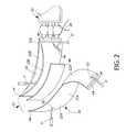
- FIG. 2is an enlarged exploded isometric view of a portion of the cumberbund of this invention shown in FIG. 1 ;
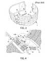
- Fig. 3is an isometric view of the prior-art cumberbund shown in FIG. 1 and for which the cumberbund of this invention is substituted;
- FIG. 4is an isometric view of an inside portion of the cumberbund of this invention showing its hidden layers for routing electrical cables therethrough;
- FIG. 5is an isometric view of one end of the cumberbund of this invention showing one exit aperture through which an internally routed cable may exit for interconnection to an externally mounted peripheral.
- FIG. 1a cumberbund constructed in accordance with one exemplary embodiment of this invention.
- the cumberbund 20(hereinafter referred to as a wired cumberbund”) is arranged to be releasably coupled to a vest 10 (or some other body-worn item, e.g., an armor carrier).
- the wired cumberbund 20is arranged to used alone or to be substituted for a conventional prior-art cumberbund 2 (like shown in FIG. 3 ), whenever desired.
- the vest 10is for illustrative purposes and is representative of various types of vests with which the subject invention can be used.
- the cumberbundcan be used by itself, for some applications, if desired.
- the vest 10includes a Pouch Attachment Ladder System (“PALS”) system for mounting Modular Lightweight Load-carrying Equipment (“MOLLE”) components thereon.
- PALSPouch Attachment Ladder System
- MOLLEModular Lightweight Load-carrying Equipment
- the vest 10includes a MOLLE enabled front pocket 12 for carrying a ruggedized computer display panel (not shown) of a computer system (not shown).
- the vest 10 and cumberbund 20together form a support system for supporting the entire computer system on the wearer.
- the front pocket 12 holding the displayis mounted on the vest 10 in a conventional manner, e.g., via the PALS system.
- the rear of the vest 10includes an internal pocket 14 in which the processor unit of the computer system is located.
- a slot 14 Ais provided for enable an electrical cable to be extended therethrough for connection to the processor unit.
- the rear of the vest 10also includes an openable/closable passageway 16 formed by a pair of VELCRO equipped flaps 16 A and 16 B to form a cumberbund support for accommodating a portion, e.g., the central rear portion 28 of the wired cumberbund 20 , to releasably secure the cumberbund and the vest to each other.
- the wired cumberbund 20is preferably fully adjustable for height and girth and is constructed somewhat similarly to a conventional PALS type cumberbund 2 , like shown in FIG. 2 , except that the wired cumberbund 20 includes layers forming internal passageways (to be described later) through which various electrical cables 4 / 4 ′/ 4 ′′ can be threaded for interconnecting various components of the computer system and/or peripherals (e.g., communication devices) to one another without such cables becoming entangled.
- peripheralse.g., communication devices
- the wired cumberbund 20basically comprises two sections 22 and 24 , which are interconnected by elastic lacing 26 at the rear 28 of the cumberbund.
- Each of the sections 22 and 24basically comprises a pair of web-like members. Only two of those members, namely, 22 A and 22 B, forming the section 22 , are shown in FIG. 2 .
- section 24also includes a similar pair of web-like members to the members 22 A and 22 B, but such members are not shown in the interest of drawing simplicity.
- the front end portion of each of the web-like sections 22 and 24 of the cumberbundincludes respective VELCRO fasteners 30 to enable the cumberbund to be releasably secured to the vest 10 or some other item.
- Each of the cumberbund sections 22 and 24comprises a pair of web-like members of similar size and shape and which are secured together.
- the member 22 Ais itself made up of a pair of fabric, e.g., nylon, layers 22 A′ and 22 A′′.
- the layer 22 A′ and the layer 22 A′′are sewn together along their respective top, bottom and side edges to form a hollow interior compartment or passageway 32 between those layers.
- the entrance to the interior compartment 32 in member 22 Ais provided by an eyelet or button-hole opening 34 ( FIGS. 2 and 4 ) on the inner layer 22 A′′ of the member 22 A.
- the exit to the interior compartment 32is in the form of an eyelet or button-hole opening 36 in the outer layer 22 A′ of that member.
- One or more electrical cablese.g., the exemplary cable designated as 4 ′, can be extended through the button-holes 34 and 36 and the interior compartment 32 to facilitate connection between any electrical components carried by the cumberbund 20 and/or vest 10 .
- the web-like member 22 Balso comprises a pair of web-like layers 22 B′ and 22 B′′ which are of similar size and shape, except that the inner layer 22 B′′ is cut away at its lower corner 40 .
- the layers 22 B′ and 22 B′′are secured together by stitching along their side and lower edges to form a hollow interior compartment or passageway 42 between those layers.
- the cut-away lower corner of the inner layer 22 B′serves as an entrance to the compartment 42 through which another cable or plural cables, e.g., exemplary cable 4 ′′ extends.
- the upper edge of the compartment 42is open along its entire length so that the other end of the cable 4 ′′ can exit from the compartment at any point along the member 22 B to facilitate connection between any electrical components carried by the cumberbund 20 and/or vest 10 .
- the two web-like members 22 A and 22 B of cumberbund section 22are secured together, e.g., sewn, other along their top and bottom edges to form a space or compartment therebetween.
- the side edges of those membersare arranged to be releasably secured together by use of cooperating VELCRO® strips 44 to seal the compartment therebetween.
- a web of soft armor 46may be disposed in the compartment between the members 22 A and 22 B, such as shown in FIG. 2 .
- the inner surface of the layer 22 B′′may be covered by an optional sheet of nylon webbing 48 as best seen in FIGS. 3 and 4 .
- Each of the layers making up the members 22 A and 22 Bis preferably formed of nylon fabric, but other materials may be used if desired. Moreover, various thicknesses and densities of the fabric materials may employed to obtain desired durability versus weight of the wired cumberbund 20 .
- the wired cumberbund 20includes PALS webbing 50 , i.e., rows of heavy-duty nylon, that are stitched onto the outer surface, e.g., fabric layer 22 A′, of the wired cumberbund 20 to allow for attachment of various MOLLE-compatible pouches and accessories.
- PALS webbing 50i.e., rows of heavy-duty nylon, that are stitched onto the outer surface, e.g., fabric layer 22 A′, of the wired cumberbund 20 to allow for attachment of various MOLLE-compatible pouches and accessories.
- the wired cumberbund 20is arranged to be interchangeable with any tactical vest (e.g., vest 10 ) or any plate carrier that employs an existing cumberbund used to secure the garment around the user's torso.
- This featureallows the user to exchange his/her existing cumberbund 2 with an electrical wired cumberbund 20 , thereby provides the wearer with the capability to instantly integrate electrical components, computers, or other peripherals on his/her body as a wearable system using his/her existing tactical vest/armor plate carrier.
- the wired cumberbund 20To install the wired cumberbund 20 on a tactical vest 10 , it is first populated with the necessary cables, e.g., cables 4 / 4 ′/ 4 ′′, and other electronic hardware (not shown) used for the intended application. Next, the existing (prior-art) cumberbund 2 is removed from the tactical vest 10 and replaced with the electronics wired cumberbund 20 . The operation may be repeated in reverse (switching back to original cumberbund 2 ) to rapidly reconfigure the user's tactical vest for multiple missions or purposes.
- cables 4 / 4 ′/ 4 ′′e.g., cables 4 / 4 ′/ 4 ′′
- other electronic hardwarenot shown
- the wired cumberbund of this inventionhas hidden layers of flat, segregated compartments or passageways sewn into the fabric that extend the length of the device. These layers allow electrical cables or other electronics to be routed through the fabric of the cumberbund and to be completely hidden. Button holes and fabric slots or “mouths” are strategically placed for the cables to exit the cumberbund. These passageways or compartments are designed to integrate cables and other electronic components, which can be configured based upon the end user's preference. By hiding (covering) the cables and electronics within the cumberbund, the total electronics system reliability is greatly increased by reducing wear and snag-hazards.
- the wired cumberbundallows the user to connect essential electronic equipment or computer peripherals to a cumberbund that is connected to a wearable tactical vest containing a computer, e.g., a mobile ultra-rugged personal computer, for ease of motion in the field.
- a wearable tactical vest containing a computere.g., a mobile ultra-rugged personal computer
- Multiple configurationsmay be exchanged rapidly by a user in such fields as public safety or military when the mission profile requires different objectives and thus a different configuration of electronic equipment or computer peripherals.
Landscapes
- Engineering & Computer Science (AREA)
- Theoretical Computer Science (AREA)
- Computer Hardware Design (AREA)
- Textile Engineering (AREA)
- Physics & Mathematics (AREA)
- General Physics & Mathematics (AREA)
- General Engineering & Computer Science (AREA)
- Health & Medical Sciences (AREA)
- General Health & Medical Sciences (AREA)
- Physical Education & Sports Medicine (AREA)
- Human Computer Interaction (AREA)
- Outer Garments And Coats (AREA)
- Professional, Industrial, Or Sporting Protective Garments (AREA)
Abstract
Description
Claims (11)
Priority Applications (3)
| Application Number | Priority Date | Filing Date | Title |
|---|---|---|---|
| US13/190,588US8814019B2 (en) | 2010-08-17 | 2011-07-26 | Reconfigurable electrical wired cumberbund |
| PCT/US2011/047326WO2012024139A1 (en) | 2010-08-17 | 2011-08-11 | Cummerbund and garment with reconfigurable electrical wired communication |
| US14/332,835US20140325737A1 (en) | 2010-08-17 | 2014-07-16 | Reconfigurable electrical wired cumberbund |
Applications Claiming Priority (2)
| Application Number | Priority Date | Filing Date | Title |
|---|---|---|---|
| US37436710P | 2010-08-17 | 2010-08-17 | |
| US13/190,588US8814019B2 (en) | 2010-08-17 | 2011-07-26 | Reconfigurable electrical wired cumberbund |
Related Child Applications (1)
| Application Number | Title | Priority Date | Filing Date |
|---|---|---|---|
| US14/332,835ContinuationUS20140325737A1 (en) | 2010-08-17 | 2014-07-16 | Reconfigurable electrical wired cumberbund |
Publications (2)
| Publication Number | Publication Date |
|---|---|
| US20120042439A1 US20120042439A1 (en) | 2012-02-23 |
| US8814019B2true US8814019B2 (en) | 2014-08-26 |
Family
ID=44584642
Family Applications (2)
| Application Number | Title | Priority Date | Filing Date |
|---|---|---|---|
| US13/190,588Active2032-08-29US8814019B2 (en) | 2010-08-17 | 2011-07-26 | Reconfigurable electrical wired cumberbund |
| US14/332,835AbandonedUS20140325737A1 (en) | 2010-08-17 | 2014-07-16 | Reconfigurable electrical wired cumberbund |
Family Applications After (1)
| Application Number | Title | Priority Date | Filing Date |
|---|---|---|---|
| US14/332,835AbandonedUS20140325737A1 (en) | 2010-08-17 | 2014-07-16 | Reconfigurable electrical wired cumberbund |
Country Status (2)
| Country | Link |
|---|---|
| US (2) | US8814019B2 (en) |
| WO (1) | WO2012024139A1 (en) |
Cited By (28)
| Publication number | Priority date | Publication date | Assignee | Title |
|---|---|---|---|---|
| US20140191706A1 (en)* | 2013-01-08 | 2014-07-10 | Mario Maese | Article of Clothing and Related Methods |
| US20160040958A1 (en)* | 2014-08-07 | 2016-02-11 | 5.11, Inc. | Hexagonal attachment system |
| USD768024S1 (en) | 2014-09-22 | 2016-10-04 | Toyota Motor Engineering & Manufacturing North America, Inc. | Necklace with a built in guidance device |
| US9578307B2 (en) | 2014-01-14 | 2017-02-21 | Toyota Motor Engineering & Manufacturing North America, Inc. | Smart necklace with stereo vision and onboard processing |
| US9576460B2 (en) | 2015-01-21 | 2017-02-21 | Toyota Motor Engineering & Manufacturing North America, Inc. | Wearable smart device for hazard detection and warning based on image and audio data |
| US9586318B2 (en) | 2015-02-27 | 2017-03-07 | Toyota Motor Engineering & Manufacturing North America, Inc. | Modular robot with smart device |
| US9629774B2 (en) | 2014-01-14 | 2017-04-25 | Toyota Motor Engineering & Manufacturing North America, Inc. | Smart necklace with stereo vision and onboard processing |
| US9677901B2 (en) | 2015-03-10 | 2017-06-13 | Toyota Motor Engineering & Manufacturing North America, Inc. | System and method for providing navigation instructions at optimal times |
| US9811752B2 (en) | 2015-03-10 | 2017-11-07 | Toyota Motor Engineering & Manufacturing North America, Inc. | Wearable smart device and method for redundant object identification |
| US9898039B2 (en) | 2015-08-03 | 2018-02-20 | Toyota Motor Engineering & Manufacturing North America, Inc. | Modular smart necklace |
| US9915545B2 (en) | 2014-01-14 | 2018-03-13 | Toyota Motor Engineering & Manufacturing North America, Inc. | Smart necklace with stereo vision and onboard processing |
| US9922236B2 (en) | 2014-09-17 | 2018-03-20 | Toyota Motor Engineering & Manufacturing North America, Inc. | Wearable eyeglasses for providing social and environmental awareness |
| US9958275B2 (en) | 2016-05-31 | 2018-05-01 | Toyota Motor Engineering & Manufacturing North America, Inc. | System and method for wearable smart device communications |
| US9972216B2 (en) | 2015-03-20 | 2018-05-15 | Toyota Motor Engineering & Manufacturing North America, Inc. | System and method for storing and playback of information for blind users |
| US10012505B2 (en) | 2016-11-11 | 2018-07-03 | Toyota Motor Engineering & Manufacturing North America, Inc. | Wearable system for providing walking directions |
| US10024678B2 (en) | 2014-09-17 | 2018-07-17 | Toyota Motor Engineering & Manufacturing North America, Inc. | Wearable clip for providing social and environmental awareness |
| US10024679B2 (en) | 2014-01-14 | 2018-07-17 | Toyota Motor Engineering & Manufacturing North America, Inc. | Smart necklace with stereo vision and onboard processing |
| US10024667B2 (en) | 2014-08-01 | 2018-07-17 | Toyota Motor Engineering & Manufacturing North America, Inc. | Wearable earpiece for providing social and environmental awareness |
| US10024680B2 (en) | 2016-03-11 | 2018-07-17 | Toyota Motor Engineering & Manufacturing North America, Inc. | Step based guidance system |
| US10172760B2 (en) | 2017-01-19 | 2019-01-08 | Jennifer Hendrix | Responsive route guidance and identification system |
| US20190029402A1 (en)* | 2017-07-31 | 2019-01-31 | Mica Manson White | Modular pack |
| US10248856B2 (en) | 2014-01-14 | 2019-04-02 | Toyota Motor Engineering & Manufacturing North America, Inc. | Smart necklace with stereo vision and onboard processing |
| US10360907B2 (en) | 2014-01-14 | 2019-07-23 | Toyota Motor Engineering & Manufacturing North America, Inc. | Smart necklace with stereo vision and onboard processing |
| US10432851B2 (en) | 2016-10-28 | 2019-10-01 | Toyota Motor Engineering & Manufacturing North America, Inc. | Wearable computing device for detecting photography |
| US10490102B2 (en) | 2015-02-10 | 2019-11-26 | Toyota Motor Engineering & Manufacturing North America, Inc. | System and method for braille assistance |
| US10521669B2 (en) | 2016-11-14 | 2019-12-31 | Toyota Motor Engineering & Manufacturing North America, Inc. | System and method for providing guidance or feedback to a user |
| US10561519B2 (en) | 2016-07-20 | 2020-02-18 | Toyota Motor Engineering & Manufacturing North America, Inc. | Wearable computing device having a curved back to reduce pressure on vertebrae |
| US20200154862A1 (en)* | 2017-07-20 | 2020-05-21 | Hewlett-Packard Development Company, L.P. | Retaining apparatuses comprising connectors |
Families Citing this family (10)
| Publication number | Priority date | Publication date | Assignee | Title |
|---|---|---|---|---|
| US9055773B2 (en)* | 2011-01-13 | 2015-06-16 | Lineweight Llc | Lightweight equipment carrying garment |
| USD717545S1 (en)* | 2013-10-24 | 2014-11-18 | James Chuang | Modular attachment adapter |
| US20150113701A1 (en)* | 2013-10-29 | 2015-04-30 | Edward E. Rice | Medical Gown with Locations for Securing Medical Tubing |
| GB2530064B (en)* | 2014-09-11 | 2016-08-24 | Thales Holdings Uk Plc | A harness |
| WO2016081765A1 (en) | 2014-11-19 | 2016-05-26 | Nike Innovate C.V. | Athletic band with removable module |
| US11666105B2 (en) | 2017-04-12 | 2023-06-06 | Nike, Inc. | Wearable article with removable module |
| EP3609587B1 (en)* | 2017-04-12 | 2023-08-02 | Nike Innovate C.V. | Wearable article with removable module |
| US10605574B2 (en)* | 2017-08-01 | 2020-03-31 | S&S Precision, Llc | Load bearing harness |
| US10993481B2 (en)* | 2018-02-13 | 2021-05-04 | Siiri Stinson | One-piece garment |
| US11779064B2 (en)* | 2019-08-16 | 2023-10-10 | Safariland, Llc | Adapter system for vest closure mechanisms |
Citations (12)
| Publication number | Priority date | Publication date | Assignee | Title |
|---|---|---|---|---|
| US1486470A (en)* | 1922-04-18 | 1924-03-11 | Welch Roy Winslow | Fisherman's belt |
| US3274476A (en)* | 1963-10-30 | 1966-09-20 | Wildum Paul | Article carrying belt |
| US4523703A (en)* | 1984-01-09 | 1985-06-18 | Mckenna George T | Coat pack |
| US4569465A (en)* | 1984-11-07 | 1986-02-11 | Farrell George T O | Stereo sport belt |
| US5211321A (en)* | 1991-11-25 | 1993-05-18 | Norton Rodriguez | Battery and equipment vest |
| US5724707A (en) | 1996-06-17 | 1998-03-10 | The United States Of America As Represented By The Secretary Of The Army | Interlock attaching strap system |
| JP2000357025A (en) | 1999-06-16 | 2000-12-26 | Shimadzu Corp | Base for wearable computer |
| US6243870B1 (en) | 2000-03-14 | 2001-06-12 | Pod Development, Inc. | Personal computer network infrastructure of an article of clothing |
| US6443347B1 (en)* | 2000-10-19 | 2002-09-03 | International Business Machines Corporation | Streamlined personal harness for supporting a wearable computer and associated equipment on the body of a user |
| WO2005031684A1 (en) | 2003-10-01 | 2005-04-07 | Adwalker Plc | An apparatus for supporting a mobile electronic display system |
| DE202007016525U1 (en) | 2007-11-23 | 2008-02-21 | Carl Zeiss Mobile Optics Gmbh | Vest for audiovisual system |
| US8079503B1 (en)* | 2006-02-08 | 2011-12-20 | Blackhawk Industries Product Group Unlimited Llc | Modular equipment coupler |
- 2011
- 2011-07-26USUS13/190,588patent/US8814019B2/enactiveActive
- 2011-08-11WOPCT/US2011/047326patent/WO2012024139A1/enactiveApplication Filing
- 2014
- 2014-07-16USUS14/332,835patent/US20140325737A1/ennot_activeAbandoned
Patent Citations (12)
| Publication number | Priority date | Publication date | Assignee | Title |
|---|---|---|---|---|
| US1486470A (en)* | 1922-04-18 | 1924-03-11 | Welch Roy Winslow | Fisherman's belt |
| US3274476A (en)* | 1963-10-30 | 1966-09-20 | Wildum Paul | Article carrying belt |
| US4523703A (en)* | 1984-01-09 | 1985-06-18 | Mckenna George T | Coat pack |
| US4569465A (en)* | 1984-11-07 | 1986-02-11 | Farrell George T O | Stereo sport belt |
| US5211321A (en)* | 1991-11-25 | 1993-05-18 | Norton Rodriguez | Battery and equipment vest |
| US5724707A (en) | 1996-06-17 | 1998-03-10 | The United States Of America As Represented By The Secretary Of The Army | Interlock attaching strap system |
| JP2000357025A (en) | 1999-06-16 | 2000-12-26 | Shimadzu Corp | Base for wearable computer |
| US6243870B1 (en) | 2000-03-14 | 2001-06-12 | Pod Development, Inc. | Personal computer network infrastructure of an article of clothing |
| US6443347B1 (en)* | 2000-10-19 | 2002-09-03 | International Business Machines Corporation | Streamlined personal harness for supporting a wearable computer and associated equipment on the body of a user |
| WO2005031684A1 (en) | 2003-10-01 | 2005-04-07 | Adwalker Plc | An apparatus for supporting a mobile electronic display system |
| US8079503B1 (en)* | 2006-02-08 | 2011-12-20 | Blackhawk Industries Product Group Unlimited Llc | Modular equipment coupler |
| DE202007016525U1 (en) | 2007-11-23 | 2008-02-21 | Carl Zeiss Mobile Optics Gmbh | Vest for audiovisual system |
Non-Patent Citations (1)
| Title |
|---|
| International Search Report for PCT/US2011/047326 mailed Nov. 11, 2011. |
Cited By (33)
| Publication number | Priority date | Publication date | Assignee | Title |
|---|---|---|---|---|
| US20140191706A1 (en)* | 2013-01-08 | 2014-07-10 | Mario Maese | Article of Clothing and Related Methods |
| US9915545B2 (en) | 2014-01-14 | 2018-03-13 | Toyota Motor Engineering & Manufacturing North America, Inc. | Smart necklace with stereo vision and onboard processing |
| US10024679B2 (en) | 2014-01-14 | 2018-07-17 | Toyota Motor Engineering & Manufacturing North America, Inc. | Smart necklace with stereo vision and onboard processing |
| US9578307B2 (en) | 2014-01-14 | 2017-02-21 | Toyota Motor Engineering & Manufacturing North America, Inc. | Smart necklace with stereo vision and onboard processing |
| US10248856B2 (en) | 2014-01-14 | 2019-04-02 | Toyota Motor Engineering & Manufacturing North America, Inc. | Smart necklace with stereo vision and onboard processing |
| US10360907B2 (en) | 2014-01-14 | 2019-07-23 | Toyota Motor Engineering & Manufacturing North America, Inc. | Smart necklace with stereo vision and onboard processing |
| US9629774B2 (en) | 2014-01-14 | 2017-04-25 | Toyota Motor Engineering & Manufacturing North America, Inc. | Smart necklace with stereo vision and onboard processing |
| US10024667B2 (en) | 2014-08-01 | 2018-07-17 | Toyota Motor Engineering & Manufacturing North America, Inc. | Wearable earpiece for providing social and environmental awareness |
| US9723909B2 (en) | 2014-08-07 | 2017-08-08 | 5.11, Inc. | Hexagonal attachment system |
| US20160040958A1 (en)* | 2014-08-07 | 2016-02-11 | 5.11, Inc. | Hexagonal attachment system |
| US9664481B2 (en)* | 2014-08-07 | 2017-05-30 | 5.11, Inc. | Hexagonal attachment system |
| US10070714B2 (en) | 2014-08-07 | 2018-09-11 | 5.11, Inc. | Hexagonal attachment system |
| USD822288S1 (en) | 2014-08-07 | 2018-07-03 | 5.11, Inc. | Attachment platform |
| US9922236B2 (en) | 2014-09-17 | 2018-03-20 | Toyota Motor Engineering & Manufacturing North America, Inc. | Wearable eyeglasses for providing social and environmental awareness |
| US10024678B2 (en) | 2014-09-17 | 2018-07-17 | Toyota Motor Engineering & Manufacturing North America, Inc. | Wearable clip for providing social and environmental awareness |
| USD768024S1 (en) | 2014-09-22 | 2016-10-04 | Toyota Motor Engineering & Manufacturing North America, Inc. | Necklace with a built in guidance device |
| US9576460B2 (en) | 2015-01-21 | 2017-02-21 | Toyota Motor Engineering & Manufacturing North America, Inc. | Wearable smart device for hazard detection and warning based on image and audio data |
| US10490102B2 (en) | 2015-02-10 | 2019-11-26 | Toyota Motor Engineering & Manufacturing North America, Inc. | System and method for braille assistance |
| US10391631B2 (en) | 2015-02-27 | 2019-08-27 | Toyota Motor Engineering & Manufacturing North America, Inc. | Modular robot with smart device |
| US9586318B2 (en) | 2015-02-27 | 2017-03-07 | Toyota Motor Engineering & Manufacturing North America, Inc. | Modular robot with smart device |
| US9677901B2 (en) | 2015-03-10 | 2017-06-13 | Toyota Motor Engineering & Manufacturing North America, Inc. | System and method for providing navigation instructions at optimal times |
| US9811752B2 (en) | 2015-03-10 | 2017-11-07 | Toyota Motor Engineering & Manufacturing North America, Inc. | Wearable smart device and method for redundant object identification |
| US9972216B2 (en) | 2015-03-20 | 2018-05-15 | Toyota Motor Engineering & Manufacturing North America, Inc. | System and method for storing and playback of information for blind users |
| US9898039B2 (en) | 2015-08-03 | 2018-02-20 | Toyota Motor Engineering & Manufacturing North America, Inc. | Modular smart necklace |
| US10024680B2 (en) | 2016-03-11 | 2018-07-17 | Toyota Motor Engineering & Manufacturing North America, Inc. | Step based guidance system |
| US9958275B2 (en) | 2016-05-31 | 2018-05-01 | Toyota Motor Engineering & Manufacturing North America, Inc. | System and method for wearable smart device communications |
| US10561519B2 (en) | 2016-07-20 | 2020-02-18 | Toyota Motor Engineering & Manufacturing North America, Inc. | Wearable computing device having a curved back to reduce pressure on vertebrae |
| US10432851B2 (en) | 2016-10-28 | 2019-10-01 | Toyota Motor Engineering & Manufacturing North America, Inc. | Wearable computing device for detecting photography |
| US10012505B2 (en) | 2016-11-11 | 2018-07-03 | Toyota Motor Engineering & Manufacturing North America, Inc. | Wearable system for providing walking directions |
| US10521669B2 (en) | 2016-11-14 | 2019-12-31 | Toyota Motor Engineering & Manufacturing North America, Inc. | System and method for providing guidance or feedback to a user |
| US10172760B2 (en) | 2017-01-19 | 2019-01-08 | Jennifer Hendrix | Responsive route guidance and identification system |
| US20200154862A1 (en)* | 2017-07-20 | 2020-05-21 | Hewlett-Packard Development Company, L.P. | Retaining apparatuses comprising connectors |
| US20190029402A1 (en)* | 2017-07-31 | 2019-01-31 | Mica Manson White | Modular pack |
Also Published As
| Publication number | Publication date |
|---|---|
| WO2012024139A1 (en) | 2012-02-23 |
| US20140325737A1 (en) | 2014-11-06 |
| US20120042439A1 (en) | 2012-02-23 |
Similar Documents
| Publication | Publication Date | Title |
|---|---|---|
| US8814019B2 (en) | Reconfigurable electrical wired cumberbund | |
| US12425549B2 (en) | Personal tactical system including garment, camera, and power distribution and data hub | |
| US11974654B2 (en) | Wearable and replaceable pouch or skin for holding a portable battery pack | |
| US11955779B2 (en) | Portable battery pack | |
| US20230309682A1 (en) | Attachment system | |
| US12082364B2 (en) | System for supplying power to at least one power distribution and data hub using a portable battery pack | |
| US9737100B2 (en) | Concealable body armor and combination bag/vest | |
| US5240156A (en) | Modular component system | |
| US20090094725A1 (en) | Clothing for Use With Personal Electronic Listening Devices | |
| US12138213B2 (en) | Tactile stimulus providing apparatus | |
| US20140259249A1 (en) | Armor Plate Carrier | |
| US20120280009A1 (en) | Hands-free wearable computer tablet holder | |
| US20120017347A1 (en) | Auxiliary Gear Attachment System and Method | |
| WO2020036643A2 (en) | Personal tactical system and network | |
| US20180368560A1 (en) | Attachment apparatus for modular load-carrying devices | |
| US9161581B2 (en) | Configurable pocket | |
| US20200288849A1 (en) | Modular back support system for backpacks other apparatus | |
| CN210353667U (en) | modular backpack | |
| WO2014083464A1 (en) | Holster harness for wearable computing |
Legal Events
| Date | Code | Title | Description |
|---|---|---|---|
| AS | Assignment | Owner name:RMT, INC., ARIZONA Free format text:ASSIGNMENT OF ASSIGNORS INTEREST;ASSIGNORS:DYSTER, JUSTIN;STIMPSON, MICHAEL;PATULSKI, NATE;AND OTHERS;SIGNING DATES FROM 20110718 TO 20110720;REEL/FRAME:026684/0306 | |
| AS | Assignment | Owner name:BLACK DIAMOND ADVANCED TECHNOLOGY, LLC, ARIZONA Free format text:ASSIGNMENT OF ASSIGNORS INTEREST;ASSIGNOR:RMT, INC.;REEL/FRAME:029746/0803 Effective date:20130124 | |
| STCF | Information on status: patent grant | Free format text:PATENTED CASE | |
| MAFP | Maintenance fee payment | Free format text:PAYMENT OF MAINTENANCE FEE, 4TH YEAR, LARGE ENTITY (ORIGINAL EVENT CODE: M1551) Year of fee payment:4 | |
| AS | Assignment | Owner name:BDATECH ACQUISITION LLC, ARIZONA Free format text:ASSIGNMENT OF ASSIGNORS INTEREST;ASSIGNOR:BLACK DIAMOND ADVANCED TECHNOLOGY, LLC;REEL/FRAME:051942/0419 Effective date:20200203 | |
| AS | Assignment | Owner name:BLACK DIAMOND ADVANCED TECHNOLOGY, LLC, ARIZONA Free format text:CHANGE OF NAME;ASSIGNOR:BDATECH ACQUISITION LLC;REEL/FRAME:052050/0719 Effective date:20200203 | |
| AS | Assignment | Owner name:FIFTH THIRD BANK, NATIONAL ASSOCIATION, ILLINOIS Free format text:SECURITY AGREEMENT;ASSIGNOR:BLACK DIAMOND ADVANCED TECHNOLOGY, LLC;REEL/FRAME:052317/0909 Effective date:20200207 | |
| MAFP | Maintenance fee payment | Free format text:PAYMENT OF MAINTENANCE FEE, 8TH YEAR, LARGE ENTITY (ORIGINAL EVENT CODE: M1552); ENTITY STATUS OF PATENT OWNER: LARGE ENTITY Year of fee payment:8 |