US8814003B2 - Beverage dispensing apparatus - Google Patents
Beverage dispensing apparatusDownload PDFInfo
- Publication number
- US8814003B2 US8814003B2US12/806,800US80680010AUS8814003B2US 8814003 B2US8814003 B2US 8814003B2US 80680010 AUS80680010 AUS 80680010AUS 8814003 B2US8814003 B2US 8814003B2
- Authority
- US
- United States
- Prior art keywords
- valve
- beverage dispensing
- manifold assembly
- assembly
- bar gun
- Prior art date
- Legal status (The legal status is an assumption and is not a legal conclusion. Google has not performed a legal analysis and makes no representation as to the accuracy of the status listed.)
- Active, expires
Links
Images


Classifications
- B—PERFORMING OPERATIONS; TRANSPORTING
- B67—OPENING, CLOSING OR CLEANING BOTTLES, JARS OR SIMILAR CONTAINERS; LIQUID HANDLING
- B67D—DISPENSING, DELIVERING OR TRANSFERRING LIQUIDS, NOT OTHERWISE PROVIDED FOR
- B67D1/00—Apparatus or devices for dispensing beverages on draught
- B67D1/0042—Details of specific parts of the dispensers
- B67D1/0081—Dispensing valves
- B67D1/0085—Dispensing valves electro-mechanical
- B67D1/0086—Hand-held gun type valves
- B—PERFORMING OPERATIONS; TRANSPORTING
- B67—OPENING, CLOSING OR CLEANING BOTTLES, JARS OR SIMILAR CONTAINERS; LIQUID HANDLING
- B67D—DISPENSING, DELIVERING OR TRANSFERRING LIQUIDS, NOT OTHERWISE PROVIDED FOR
- B67D1/00—Apparatus or devices for dispensing beverages on draught
- B67D1/0015—Apparatus or devices for dispensing beverages on draught the beverage being prepared by mixing at least two liquid components
- B67D1/0021—Apparatus or devices for dispensing beverages on draught the beverage being prepared by mixing at least two liquid components the components being mixed at the time of dispensing, i.e. post-mix dispensers
- B—PERFORMING OPERATIONS; TRANSPORTING
- B67—OPENING, CLOSING OR CLEANING BOTTLES, JARS OR SIMILAR CONTAINERS; LIQUID HANDLING
- B67D—DISPENSING, DELIVERING OR TRANSFERRING LIQUIDS, NOT OTHERWISE PROVIDED FOR
- B67D1/00—Apparatus or devices for dispensing beverages on draught
- B67D1/0042—Details of specific parts of the dispensers
- B67D1/0081—Dispensing valves
- B—PERFORMING OPERATIONS; TRANSPORTING
- B67—OPENING, CLOSING OR CLEANING BOTTLES, JARS OR SIMILAR CONTAINERS; LIQUID HANDLING
- B67D—DISPENSING, DELIVERING OR TRANSFERRING LIQUIDS, NOT OTHERWISE PROVIDED FOR
- B67D1/00—Apparatus or devices for dispensing beverages on draught
- B67D1/08—Details
- B67D1/0857—Cooling arrangements
- B67D1/0858—Cooling arrangements using compression systems
- B67D1/0861—Cooling arrangements using compression systems the evaporator acting through an intermediate heat transfer means
- B67D1/0865—Cooling arrangements using compression systems the evaporator acting through an intermediate heat transfer means by circulating a cooling fluid along beverage supply lines, e.g. pythons
- B67D1/0867—Cooling arrangements using compression systems the evaporator acting through an intermediate heat transfer means by circulating a cooling fluid along beverage supply lines, e.g. pythons the cooling fluid being a liquid
- B—PERFORMING OPERATIONS; TRANSPORTING
- B67—OPENING, CLOSING OR CLEANING BOTTLES, JARS OR SIMILAR CONTAINERS; LIQUID HANDLING
- B67D—DISPENSING, DELIVERING OR TRANSFERRING LIQUIDS, NOT OTHERWISE PROVIDED FOR
- B67D7/00—Apparatus or devices for transferring liquids from bulk storage containers or reservoirs into vehicles or into portable containers, e.g. for retail sale purposes
- B67D7/06—Details or accessories
- B67D7/80—Arrangements of heating or cooling devices for liquids to be transferred
- B—PERFORMING OPERATIONS; TRANSPORTING
- B67—OPENING, CLOSING OR CLEANING BOTTLES, JARS OR SIMILAR CONTAINERS; LIQUID HANDLING
- B67D—DISPENSING, DELIVERING OR TRANSFERRING LIQUIDS, NOT OTHERWISE PROVIDED FOR
- B67D1/00—Apparatus or devices for dispensing beverages on draught
- B67D1/0042—Details of specific parts of the dispensers
- B67D1/0081—Dispensing valves
- B67D2001/0087—Dispensing valves being mounted on the dispenser housing
Definitions
- Beverage dispensing systemshaving bar guns, more particularly, a beverage dispensing system for dispensing multiple beverages therefrom, which contains a bar gun, which bar gun has a recirculation loop for substantially continuous recirculation of cool liquids.
- Dispensing systemsincluding beverage dispensing systems having bar guns that are well-known in the art. Bar guns are designed to dispense multiple beverages therefrom, typically receiving a number of different types of syrup from a number of separate sources, as well as carbonated water. Typically, pressing a button for the desired beverage on the bar gun will valve both the carbonated water (soda) and the syrup for post-mixing and dispensing into a cup as known in the art.
- Typical beverage dispensing systems of the bar gun post-mix typetypically include remote vessels for the soda, which vessel is typically maintained at a cooled temperature. Trunk lines are provided from the main remote carbonated soda (out) and/or beverage syrup vessels (out), which trunk lines provide fluid under pressure to, typically, a multiplicity of remote bar guns. As is known in the art, the trunk lines carrying cooled fluid, typically soda water, carry fluid to the bar guns through a valve and manifold assembly. One of the functions of the manifold and valve assembly is to provide individual on/off valves to each of the multiplicity of lines (soda and syrup) entering the valve and manifold assembly, as well as providing individual valved channels, which valved (flow controlled) channels have valves engaged therewith.
- the valvesmay be flow control valves or mechanically set adjustable orifice valves, but in either case, they are designed to control the flow rate of the fluid (syrup or soda) flowing therethrough so as to properly mix the soda/syrup at the bar gun nozzle, so that it will be neither too strong nor too weak. All of the foregoing describes structures and functions well-known in the art.
- a beverage dispensing apparatuscomprising a bar gun assembly; a valve and manifold assembly; a trunk line carrying a cool fluid and circulating through a cooler; a multiplicity of concentrate bearing lines engaging a multiplicity of concentrated sources to the upstream side of the valve and manifold assembly; a python for carrying a plurality of python fluid lines engaging the valve and manifold assembly and located between the downstream side of the valve and manifold assembly and the bar gun assembly, the python fluid lines including a multiplicity of concentrate carrying lines engaging the bar gun assembly and also including at least a valve and manifold assembly out line and a valve and manifold assembly return coolant line; an inline for carrying the cool fluid from the trunk line to the upstream side of the valve and manifold assembly and an outline carrying the cool fluid from the upstream side of the valve and manifold assembly to the trunk line; and a recirculation loop downstream of the valve and manifold assembly for engaging the out and return coolant lines of the valve and manifold assembly
- a beverage dispensing apparatuswherein the recirculation loop is located in the bar gun assembly.
- a beverage dispensing apparatuswherein the recirculation loop is located in the python near the bar gun assembly.
- a beverage dispensing apparatuswherein the bar gun assembly includes a heel and a handle.
- a beverage dispensing apparatuswherein the recirculation loop is located in the heel of the bar gun assembly.
- a beverage dispensing apparatuswherein the recirculation loop is located in the handle of the bar gun assembly.
- a beverage dispensing apparatuswherein the recirculation loop includes a substantially hollow “U”-shaped member.
- a beverage dispensing apparatuswherein the recirculation loop includes a substantially hollow “U”-shaped member, wherein the “U”-shaped member includes a pair of legs and a cross-piece joining the pair of legs.
- a beverage dispensing apparatuswherein a first leg of the pair of legs fluidly joins the python out line and the second leg of the pair of legs joins the python inline
- a beverage dispensing apparatusfurther including means to assist in fluidly engaging the pair of legs to the two python lines.
- a beverage dispensing apparatusfurther including a bypass line for carrying cool fluid past the valve and manifold assembly without engaging the same.
- a beverage dispensing apparatuswherein the recirculation loop is located in the bar gun assembly.
- a beverage dispensing apparatuswherein the recirculation loop is located in the python near the bar gun assembly.
- a beverage dispensing apparatuswherein the bar gun assembly includes a heel and a handle.
- a beverage dispensing apparatuswherein the recirculation loop is located in the heel of the bar gun assembly.
- a beverage dispensing apparatuswherein the recirculation loop is located in the handle of the bar gun assembly.
- a beverage dispensing apparatuswherein the python includes insulation near the recirculation loop.
- a beverage dispensing apparatuswherein the bar gun assembly includes insulation near the recirculation loop.
- a beverage dispensing apparatuscomprising a bar gun assembly; a valve and manifold assembly; a trunk line carrying a cool fluid and circulating through a cooler; a multiplicity of concentrate bearing lines engaging a multiplicity of concentrated sources to the upstream side of the valve and manifold assembly; a python for carrying a plurality of fluid lines engaging the valve and manifold assembly and located between the downstream side of the valve and manifold assembly and the bar gun assembly, including a multiplicity of concentrate carrying lines engaging the bar gun assembly and also including at least a valve and manifold assembly out line and a valve and manifold assembly return coolant line; an inline for carrying the cool fluid from the trunk line to the upstream side of the valve and manifold assembly and an outline carrying the cool fluid from the upstream side of the valve and manifold assembly to the trunk line; a recirculation loop downstream of the valve and manifold assembly for engaging the out and return coolant lines of the valve and manifold assembly; and further including a bypass line for carrying cool fluid past the
- a beverage dispensing apparatuswherein the bar gun assembly includes insulation near the recirculation loop.
- a beverage dispensing apparatuswherein the bar gun assembly includes a heel and a handle.
- a beverage dispensing apparatuswherein the recirculation loop is located in the heel of the bar gun assembly.
- a beverage dispensing apparatuswherein the recirculation loop is located in the handle of the bar gun assembly.
- a beverage dispensing apparatusfurther including insulation adjacent the recirculation loop.
- a beverage dispensing apparatusfurther including insulation adjacent the recirculation loop.
- a beverage dispensing apparatuscomprising a bar gun assembly; a valve and manifold assembly; a trunk line carrying a cool fluid and circulating through a cooler; a multiplicity of concentrate bearing lines engaging a multiplicity of concentrated sources to the upstream side of the valve and manifold assembly; a python for carrying a plurality of python fluid lines engaging the valve and manifold assembly and located between the downstream side of the valve and manifold assembly and the bar gun assembly, the python fluid lines including a multiplicity of concentrate carrying lines engaging the bar gun assembly and also including at least a valve and manifold assembly out line and a valve and manifold assembly return coolant line; an inline for carrying the cool fluid from the trunk line to the upstream side of the valve and manifold assembly and an outline carrying the cool fluid from the upstream side of the valve and manifold assembly to the trunk line; and a recirculation loop downstream of the valve and manifold assembly for engaging the out and return coolant lines of the valve and manifold assembly
- a beverage dispensing apparatuswherein the bar gun assembly includes a heel and a handle.
- a beverage dispensing apparatuswherein the recirculation loop is located in the heel of the bar gun assembly.
- a beverage dispensing systemcomprising a multiplicity of assemblies, each of the multiplicity of assembles engaging a trunk line carrying a cool fluid and circulating through a cooler, each assembly of the multiplicity of assemblies including; a bar gun assembly; a valve and manifold assembly; a multiplicity of concentrate bearing lines engaging a multiplicity of concentrated sources to the upstream side of the valve and manifold assembly; a python for carrying a plurality of python fluid lines engaging the valve and manifold assembly and located between the downstream side of the valve and manifold assembly and the bar gun assembly, the python fluid lines including a multiplicity of concentrate carrying lines engaging the bar gun assembly and also including at least a valve and manifold assembly out line and a valve and manifold assembly return coolant line; an inline for carrying the cool fluid from the trunk line to the upstream side of the valve and manifold assembly and an outline carrying the cool fluid from the upstream side of the valve and manifold assembly to the trunk line; and recirculation loop downstream
- a beverage dispensing system of claim 1further including a splitter for carrying the coolant therethrough, and wherein one of the python lines is adapted to engage, via the valve and manifold assembly, the splitter, for carrying cooling fluid therein to the bar gun assembly for dispensing therefrom.
- a beverage dispensing system of claim 18further including a splitter for carrying the coolant therethrough, and wherein one of the python lines is adapted to engage, via the valve and manifold assembly, the splitter, for carrying cooling fluid to the bar gun assembly for dispensing therefrom.
- a beverage dispensing system of claim 27further including a splitter for carrying the coolant therethrough, and wherein one of the python lines is adapted to engage, via the valve and manifold assembly, the splitter, for carrying cooling fluid to the bar gun assembly for dispensing therefrom.
- a beverage dispensing system of claim 30further including a splitter for carrying coolant therethrough, and wherein one of the python lines is adapted to engage, via the valve and manifold assembly, the splitter, for dispensing cooling fluid therefrom.
- One featureis a recirculation loop, which recirculates coolant (typically carbonated water or water), from the cool trunk line carrying the coolant through the valve and manifold assembly, then through the python and into the bar gun, returning (undispensed) back through the python and through the valve and manifold assembly into the trunk line.
- This recirculation loopis operational even when the bar gun is not in use. That is to say, the recirculation loop will recirculate coolant from the trunk line through the python and valve assembly into the coolant trunk line.
- This recirculation loopis valved for flow even when the bar gun is not in use (that is to say, when none of the buttons on the bar gun are actively dispensing fluid therefrom).
- the recirculation loopmay be situated in the bar gun handle, in the heel or in the python, where it would typically be situated proximate the bar gun handle.
- the structure providing recirculationwill direct fluid from a direction towards the dispensing nozzle to a direction away from a dispensing nozzle and back towards the valve and manifold assembly.
- this structure that will redirect the cooling fluidit may be located in the bar gun handle itself, in one embodiment, and in a second embodiment, may be located in the heel of the apparatus, or it may be located in the python.
- the structure of the recirculation loopis downstream of the valve and manifold assembly. This is unlike the prior art in which it is known to deliver cooling fluid up to, but not into, the valve and manifold assembly.
- the recirculation loopmay be open or closed.
- the cool fluidmay be drawn off and mixed with syrup and dispensed as product into a cup for a consumer.
- the cooling fluidis compatible with the beverage and may be drunk by the consumer.
- an open systemwould use cooled soda water.
- a closed systemthere is no structure or function providing for the drawing off of cooling fluid to dispense into a container.
- fluidssuch as glycol or the like may be used. There is no need to worry, in a closed system, about the compatibility of the cooled fluid for human consumption.
- a third featurewhich may be used alone or in combination with the recirculation loop, is the providing of insulation in various parts of the valve and manifold assembly and/or the python or the bar gun of the bar gun assembly.
- This insulationwill help prevent heat loss by radiation, conduction and/or convection from the fluid in the valve and manifold assembly and/or the sheath and may assist in the transfer of heat between the coolant fluid and the uncooled fluids carried by respective conduits in the python.
- Insulationin one example a pocket of air adjacent the recirculation loop, may help avoid the excessive cooling of the exterior of the bar gun body. Excessive cooling of a bar gun resting unused over a period of time, while good for the first dispensing of a cool drink, may cause the bar gun surface to form condensation thereon, as “sweat.”
- the position of the recirculation loop in the apparatuswill help prevent “sweating” of the bar gun body.
- the use of insulationwill also help prevent “sweating” of the bar gun body.
- the recirculation loopis used in conjunction with the insulation to provide for effective prevention of heat loss from the liquids of the bar gun assembly and/or sweating of the bar gun body.
- FIG. 1Ais a schematic illustration of the elements of a recirculation loop of the bar gun system.
- FIG. 1Bis a top elevational view of the elements of the recirculation loop as they apply to the trunk line, valve and manifold assembly, and python.
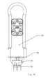
- FIG. 1Cis a top elevational view of the bar gun illustrating the recirculation channel therein.
- FIG. 1Dis an alternate configuration of lines carrying fluid to the valve and manifold assembly.
- FIG. 1Eillustrates a closed system
- FIG. 1Fis a schematic illustration of a beverage dispensing system comprising multiple beverage dispensing apparatus operating off a common coolant line.
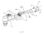
- FIG. 2Ais a perspective view of the manner in which the python joins the bar gun illustrating details of the insulation used as well as the arrangement of the lines incorporating the recirculation loop.
- FIG. 2Bis a cross-section elevational view of some of the elements illustrated in FIG. 2A .
- FIG. 2Cis a cross-section elevational view of the elements illustrated in FIG. 2A where a recirculation channel is situated in the python proximate the heel of the bar gun assembly.
- FIG. 3is an exploded perspective view of the manifold portion of the valve and manifold assembly illustrating the manner in which insulation is used therewith and the manner in which it joins the python.
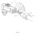
- FIGS. 4A , 4 B, and 4 Care illustrations of an alternate preferred embodiment of Applicant's recirculation loop.
- FIGS. 4A and 4Bshow the U-shape fitting exploded away from lines 50 and 52
- FIG. 4Cshows the fitting as it is used, attached to the removed ends of lines 50 and 52 .
- FIGS. 1A , 1 B, and 1 Cillustrate various elements, structurally and functionally, of beverage dispensing apparatus that may comprise Applicants' recirculation loop 10 .
- the recirculation loop 10is designed to help prevent heat loss in the valve and manifold assembly and the elements downstream thereof, including the python and bar gun assembly 13 .
- recirculating cool fluidis a fluid that may be dispensed through the bar gun.
- Suitable fluidsinclude, but are not limited to: soda water, carbonated water, water, consumable liquefied gases, or consumable gaseous fluids such as carbon dioxide, which when mixed with the other liquids in the bar gun carbonates the dispensed beverage.
- consumable liquefied gases and consumable gaseous fluidsthe Applicant is referring to such gases and fluids which are known to be consumable in certain proportions by human beings without harm.
- recirculation fluid Riinto a splitter 26 having branch 26 a and branch 26 b .
- Recirculation fluid Riwill pass through V 1 and as dispensed coolant; typically carbonated water through V 2 , which are two of a multiplicity of valves 18 .
- Valves 18may be of the flow control type or adjustable/fixed orifice type, but in any case are valves known in the art to control the flow of fluids therethrough. In conjunction with a multiplicity of valves 18 (engaged with channels therethrough) may be shutoff or ball valves 20 as known in the art.
- a bypass line 46may extend between the in line 42 and the out line 44 . Hence, whilst some of the coolant passes through the recirculation channel 30 , some of the coolant passes directly into the out line, without passing through the recirculation channel 30 .
- the relative proportion of coolant passing through the recirculation channel 30 and the bypass line 46maybe influenced by the setting of valves V 1 and V 3 , the relative sizes of the in line 42 , out line 44 and bypass line 46 for example.
- recirculation fluid (coolant) passing through branch 26 awill be destined to return through V 3 and out line 44 as Ro (recirculation of the fluid out).
- Rorecirculation of the fluid out.
- the bar gunis not being used, that is, none of the beverages are being dispensed, then it may be seen that substantially no flow will occur through branch 26 b , valve V 2 , and the line marked “carb” (for carbonated water or soda water). That is to say, the recirculation loop operates primarily in a mode in which none of the buttons (actuating valves as known in the art) of the bar gun are being depressed and no beverage is being dispensed.
- recirculating fluid Riwill circulate in the channels and lines as illustrated up to recirculation channel 30 where it will perform a substantial “U-turn” and return as recirculation out or Ro through line 44 and into the trunk return line 40 a .
- the trunk linetypically carries chilled carbonated fluid and thus has an out line 40 which services a number of bar gun assemblies 13 (see FIG. 1F ) and a return line 40 a engaging a source 1 of carbonated water or soda cooled by a chiller 1 as known in the art and including a recirculation pump 3 as known in the art.
- Valves V 1 and/or V 3may be adjusted to control the flow rate of recirculation fluid therethrough.
- a splitteris not necessary to the recirculation loop, line 42 may go directly into the fitting that, in illustration FIG. 1A , engages branch 26 a and the fitting engaging branch 26 b will receive the product from the trunk line as known in the art.
- Such an arrangementalso provides for a closed system where the coolant fluid is not used in the mixing of beverages.
- coolant fluidcould be ethylene glycol or another known refrigerant.
- FIG. 1Fillustrates multiple (four) flow control/python/bar gun assembly systems 60 A/ 60 B/ 60 C/ 60 D. Each is comprised of at least elements 12 / 13 / 28 / 42 / 44 / 46 /V 1 /V 3 . That is to say, coming off the trunk line or coolant main line, the system 60 A/ 60 B/ 60 C/ 60 D comprising a flow control/python/bar gun assembly is typically provided at multiple places.
- V 1 or V 3 at 60 Awill affect the crossover or bypass coolant fluid going through 46 and back into the main coolant line. Specifically, either V 1 or V 3 may be adjusted to choke down or reduce the flow of coolant therethrough and therefore to the recirculation loop of the python and/or bar gun assemblies. Then, more of that fluid will go through line 46 and be available as fluid typically a little bit cooler than the fluid that went through the python 28 of 60 A. Increasing the flow of fluid through python 28 of 60 A will provide a cooler temperature at the elements downstream of 46 on 60 A, but will provide a slightly higher temperature to downstream elements 60 B/ 60 C/ 60 D.
- valves V 1 or V 3at each of the stations, the amount of cool fluid going into the recirculation loops at each station can be controlled and the flow to the recirculation loop can be increased for more coolant or decreased.
- increased flow at any recirculation loopwill slightly decrease the ability for downstream stations (for example, station 60 B/ 60 C/ 60 D which are downstream from 60 A) to cool themselves.
- FIGS. 1A-1CA number of the other elements illustrated in FIGS. 1A-1C are known in the art. Locking slides 22 and fittings 24 removably engage a number of typically flexible fluid lines to the valve and manifold assembly 12 .
- Pythons 28are known in the art and include outer sheath 34 and carry a number of fluid bearing lines therethrough, here four syrup lines and a carb line.
- the python of the present inventionis also carrying a line for recirculation fluid Ri designated 50 and a line for Ro designated 52 as illustrated. Lines 50 and 52 originate at the manifold assembly, run through the python, and in one embodiment engage recirculation channel 30 , and in a second embodiment ( FIGS.
- Both a “U” shaped fitting 54 and the recirculation channel 30will signify a structural member or element adapted to reverse the flow of coolant from towards the dispensing nozzle to away from the dispensing nozzle.
- Additional features of Applicants' present deviceare also provided in an effort to achieve a reduction of heat loss to the environment from the fluids in the lines and valves and other elements of the valve and manifold assembly, python and/or bar gun assembly.
- An additional featureincludes the use of insulation including, typically, tubular insulation at least partially within python 28 as illustrated in FIGS. 2A and 2B . That is to say, python 28 may, in addition to having outer sheath 34 , carry insulation 36 , which may be tubular and which may be located within or on the outside of outer sheath 34 (illustrated is an inner python sheath insulation 36 ). In the manner illustrated, insulation preferably wraps or at least partially wraps the multiplicity of lines within the python, including Ri and Ro, those lines carrying the recirculated fluid (coolant). The sheath 34 may be combined with sheath insulation 36 as a single unit combining flexibility, insulation and an annulus or channel therethrough.
- python insulation sheath 30may extend slightly beyond outer sheath 34 (upstream end) and may be wrapped with an insulated tape 38 to help protect and further insulate the lines within the python and extending past the python into body 13 A of the bar gun.
- Tape 38may be an insulation type tape (preferably adhesive bearing) and may help prevent chafing of the lines.
- the insulation 36may in addition to preventing heat loss may also increase heat transfer between conduits carrying cooled fluid and those carrying uncooled fluid by bringing them into closer proximity.
- the fluid carrying lines and the insulation 36 , 38may be so shaped and dimensioned as to squeeze together (but not crush) fluid carrying conduits so that heat exchange between adjacent conduits is at least partially by conduction.
- FIG. 2Cthe parts illustrated are essentially the same as shown in FIG. 2 b , except that the recirculation channel 30 is situated in the python proximate the heel 32 of the bar gun assembly.
- manifold insulation 48may be used in conjunction with any of the other elements of Applicants' design. More particularly, FIG. 3 . illustrates the use of manifold insulation at least partially within manifold covers 14 a / 14 b , which covers comprise a manifold housing. Manifold insulation 48 may be internal, that is to say, within the housing and may at least partially rest adjacent the multiplicity of lines passing through the manifold from the valve assembly 16 to manifold 14 into python 28 .
- FIG. 1Dillustrates alternative embodiments for bringing cool recirculation fluid and product (or multiple products) to the valve and manifold assembly from a source.
- the recirculation fluid usedwill be chilled, before entering the recirculation loop, product dispensed may or may not be.
- Types of insulationthat may be used include, but are not limited to, foam, armaflex, fiberglass, flat, tubular tape, etc. Where the product dispensed for example syrup is not cooled, this product may be delivered via a fluid line other than trunk line 40 in ways known in the art.
- FIG. 1Eillustrates an alternative embodiment where a separate supply of product 2 ′ is delivered to the bar gun assembly 13 by a pump 3 ′ from a chiller 1 ′.
- a separate supply of product 2 ′is delivered to the bar gun assembly 13 by a pump 3 ′ from a chiller 1 ′.
- Recirculation fluid passing through branch 26 a and V 1 as Riwill be destined to return through V 3 and out line 44 as Ro (recirculation of the fluid out).
- the recirculation loopoperates in the same manner whether buttons to dispense beverage are actuated or not, i.e. whether product flows through branch 26 b or not.
- Recirculating fluid Riwill circulate in the channels and lines as illustrated up to recirculation channel 30 where it will perform a substantial “U-turn” and return as recirculation out or Ro through line 44 and into the trunk return line 40 a .
- the trunk linetypically carries glycol or the like and has an out line 40 which services a number of bar gun assemblies 13 and a return line 40 a engaging a source of glycol 2 cooled by a chiller 1 as known in the art and including a recirculation pump 3 as known in the art.
- Valves V 1 and/or V 3may be adjusted to control the flow rate of recirculation fluid therethrough. Indeed, valves V 1 and V 3 may be used, but are not necessary—the recirculation fluid may flow unvalved. Valve V 2 may be adjusted to control flow of the product flowing therethrough.
- FIGS. 4A , 4 B, and 4 Cillustrate an alternate preferred embodiment from that described above and as set forth in the previous Figures.
- the rerouting or reversal of the incoming fluid Ri to the outgoing fluid Rooccurs not in bar gun body 13 A, like described above.
- U-shape fitting 54typically engages the removed ends of lines 50 and 52 between the heel 32 of the bar gun assembly and the removed end of the sheath. That is to say, U-shape fitting 54 engages the removed ends 50 a / 52 a in a fluid sealing fashion and when heel 32 is attached, through fasteners to the rear of body 13 A of the bar gun assembly, U-shape fitting 54 is typically located substantially in the space just beyond the end of python 28 and the mounting plate 58 .
- FIG. 4Cshows the fitting attached, as in use (but for clarity deletes heel, insulation, and python). With the U-shape fitting 54 mounted as illustrated in FIGS. 4A-4C , when assembled the U-shape fitting is covered by heel 32 .
- U-shape fitting 54is substantially hollow and incoming fluid from line 50 enters the leg attached to line 50 and passes through body 54 c , and into line 52 .
- U-shape fitting 54recirculates incoming fluid from line 50 to line 52 as outgoing fluid Ro.
- this recirculationoccurs without the recirculation fluid (typically cool fluid recirculating at times when the bar gun is not in use) entering body 13 A of the bar gun assembly.
- the insulationtapee, foam or other suitable insulation
- the sheathcan be used to at least partially cover U-shape fitting 54 . In this fashion, with the coolant fluid avoiding contact with the bar gun body itself, the problem of bar gun “sweating” is avoided.
- U-shape fitting 54having hollow legs 54 a with barbs 54 b at the removed end thereof and having hollow body 54 c would provide for snug fit of ends 50 a and 52 a over barbs 54 b .
- slidable, flexible collars 56may, after the ends of lines 50 and 52 are engaged to legs 54 a , be moved up and to partially engage the outside of ends 50 a and 52 a and, optionally, part of legs 54 a to provide a snug, slip-resistant fitting of lines 50 and 52 to U-shape fitting 54 .
- the u-shape fitting 54may be situated within the sheath 34 , preferably proximate the end thereof which attaches to the bar gun assembly.
Landscapes
- Physics & Mathematics (AREA)
- Thermal Sciences (AREA)
- Engineering & Computer Science (AREA)
- Mechanical Engineering (AREA)
- Devices For Dispensing Beverages (AREA)
Abstract
Description
Claims (51)
Priority Applications (3)
| Application Number | Priority Date | Filing Date | Title |
|---|---|---|---|
| US12/806,800US8814003B2 (en) | 2009-08-21 | 2010-08-20 | Beverage dispensing apparatus |
| AU2010235929AAU2010235929A1 (en) | 2009-12-16 | 2010-10-21 | Beverage dispensing apparatus |
| US14/461,917US9840406B2 (en) | 2009-08-21 | 2014-08-18 | Beverage dispensing apparatus |
Applications Claiming Priority (3)
| Application Number | Priority Date | Filing Date | Title |
|---|---|---|---|
| US23587209P | 2009-08-21 | 2009-08-21 | |
| US28704309P | 2009-12-16 | 2009-12-16 | |
| US12/806,800US8814003B2 (en) | 2009-08-21 | 2010-08-20 | Beverage dispensing apparatus |
Related Child Applications (1)
| Application Number | Title | Priority Date | Filing Date |
|---|---|---|---|
| US14/461,917ContinuationUS9840406B2 (en) | 2009-08-21 | 2014-08-18 | Beverage dispensing apparatus |
Publications (2)
| Publication Number | Publication Date |
|---|---|
| US20110042415A1 US20110042415A1 (en) | 2011-02-24 |
| US8814003B2true US8814003B2 (en) | 2014-08-26 |
Family
ID=42984345
Family Applications (2)
| Application Number | Title | Priority Date | Filing Date |
|---|---|---|---|
| US12/806,800Active2030-10-11US8814003B2 (en) | 2009-08-21 | 2010-08-20 | Beverage dispensing apparatus |
| US14/461,917Active2031-11-04US9840406B2 (en) | 2009-08-21 | 2014-08-18 | Beverage dispensing apparatus |
Family Applications After (1)
| Application Number | Title | Priority Date | Filing Date |
|---|---|---|---|
| US14/461,917Active2031-11-04US9840406B2 (en) | 2009-08-21 | 2014-08-18 | Beverage dispensing apparatus |
Country Status (2)
| Country | Link |
|---|---|
| US (2) | US8814003B2 (en) |
| GB (1) | GB2474741B (en) |
Cited By (11)
| Publication number | Priority date | Publication date | Assignee | Title |
|---|---|---|---|---|
| US20160106136A1 (en)* | 2014-10-20 | 2016-04-21 | Keurig Green Mountain, Inc. | Flow circuit for carbonated beverage machine |
| US20160153708A1 (en)* | 2011-11-16 | 2016-06-02 | Automatic Bar Controls, Inc. | Beverage dispensing apparatus with a refrigerated dispensing tube bundle and a method of cooling beverage fluids |
| US9417652B2 (en)* | 2014-07-14 | 2016-08-16 | Automatic Bar Controls, Inc. | Beverage dispensing apparatus with lever assembly |
| USD786616S1 (en)* | 2012-07-02 | 2017-05-16 | Sam Brown | Bar gun |
| US11345584B2 (en) | 2020-06-04 | 2022-05-31 | Lancer Corporation | Hand-held dispenser and related methods |
| USD957187S1 (en) | 2020-12-11 | 2022-07-12 | Lancer Corporation | Bar gun |
| USD987367S1 (en) | 2021-10-20 | 2023-05-30 | Lancer Corporation | Bar gun |
| USD987370S1 (en) | 2021-10-20 | 2023-05-30 | Lancer Corporation | Bar gun |
| USD987368S1 (en) | 2021-10-20 | 2023-05-30 | Lancer Corporation | Bar gun |
| USD987369S1 (en) | 2021-10-20 | 2023-05-30 | Lancer Corporation | Bar gun |
| WO2023250049A1 (en)* | 2022-06-21 | 2023-12-28 | Lancer Corporation | Fluid line connector arrangements for hand-held beverage dispensers and related methods for use |
Families Citing this family (11)
| Publication number | Priority date | Publication date | Assignee | Title |
|---|---|---|---|---|
| US10906794B2 (en)* | 2006-10-20 | 2021-02-02 | Bevrage Group U.S.A Llc | Beverage dispensing cooler |
| USD658486S1 (en)* | 2010-12-02 | 2012-05-01 | Hecht Thomas R | Mounting plate |
| US9010579B2 (en)* | 2011-08-23 | 2015-04-21 | Automatic Bar Controls, Inc. | Manifold module for beverage dispensing system |
| US20140203039A1 (en)* | 2011-09-26 | 2014-07-24 | Dispensing Technologies B.V. | SYSTEMS AND METHODS FOR DISPENSING ONE OR MORE LIQUIDS FROM A PORTABLE SELF-CONTAINED APPARATUS ("Industrial Flair") |
| IN2014CN02500A (en) | 2011-10-11 | 2015-06-26 | Flow Control LLC | |
| WO2013112895A1 (en)* | 2012-01-25 | 2013-08-01 | Schroeder Industries, Inc. D/B/A Schroeder America | A modular beverage dispenser having a built-in cold plate and carbonator |
| EP3183205A4 (en)* | 2014-08-29 | 2018-03-21 | Automatic Bar Controls, Inc. | Beverage dispensing apparatus with sensor assembly for sensing dispensing of beverage |
| CA3069297C (en) | 2017-07-10 | 2021-06-01 | Flow Control Llc. | Dispense tap with integral infusion |
| USD907957S1 (en)* | 2018-10-12 | 2021-01-19 | Rich Products Corporation | Dispensing fitment |
| USD941088S1 (en)* | 2019-03-26 | 2022-01-18 | Rich Products Corporation | Dispensing fitment |
| US11339045B2 (en) | 2020-10-20 | 2022-05-24 | Elkay Manufacturing Company | Flavor and additive delivery systems and methods for beverage dispensers |
Citations (116)
| Publication number | Priority date | Publication date | Assignee | Title |
|---|---|---|---|---|
| US1627147A (en) | 1926-03-09 | 1927-05-03 | Dolph M Clark | Coffee-urn attachment to automatically measure more than one substance simultaneously to deliver a combined uniform volume |
| US1947329A (en) | 1930-10-16 | 1934-02-13 | Bastian Blessing Co | Faucet |
| US2478586A (en) | 1946-12-12 | 1949-08-09 | John T Krapp | Coupling |
| US2682386A (en) | 1948-12-13 | 1954-06-29 | Lindsay Company | Valve mechanism |
| US2887250A (en) | 1958-09-16 | 1959-05-19 | Carl S Zilk | Dispensing apapratus |
| US2937792A (en) | 1958-03-10 | 1960-05-24 | Clarence D Firstenberg | Soda dispensing device |
| US3009653A (en) | 1960-05-06 | 1961-11-21 | Robert M Hedeman | Multi-flavor drink dispenser |
| US3013701A (en) | 1958-05-29 | 1961-12-19 | Vendomatic Sales Inc | Apparatus for mixing powdered base and liquid to produce a beverage |
| US3108779A (en) | 1959-11-12 | 1963-10-29 | Acf Ind Inc | Valve having a valve seat of very thin material |
| US3326520A (en) | 1964-03-25 | 1967-06-20 | Rubber Electronic Ind | Resilient needle valve element |
| US3619668A (en) | 1970-08-27 | 1971-11-09 | Honeywell Inc | Minimum off-time circuit |
| US3643754A (en) | 1969-02-21 | 1972-02-22 | Stal Refrigeration Ab | Apparatus for cooling a liquid |
| GB1300072A (en) | 1969-12-10 | 1972-12-20 | Kuroda Gauge Mfg | Improvements in and relating to fluid logic circuit elements |
| US3867962A (en) | 1973-04-24 | 1975-02-25 | Bruce Gerrard | Beverage dispensing valve |
| US3963317A (en) | 1975-04-03 | 1976-06-15 | E. I. Du Pont De Nemours And Company | Zero force edge connector block |
| US4094445A (en) | 1973-03-29 | 1978-06-13 | Elliott-Lewis Corporation | High speed beer dispensing method |
| US4098295A (en) | 1976-12-27 | 1978-07-04 | Pneutek, Inc. | Control valves |
| US4196886A (en) | 1975-07-21 | 1980-04-08 | Industrial Electronic Rubber Co. | Fluid control valve |
| US4219046A (en) | 1978-07-17 | 1980-08-26 | The Dow Chemical Company | Plug valve and method |
| US4390224A (en) | 1981-05-14 | 1983-06-28 | Amp Incorporated | Two piece zero insertion force connector |
| GB2042354B (en) | 1979-02-21 | 1983-08-17 | Cornelius Co | Multiple flavour post-mix dispensing head |
| US4433795A (en) | 1981-07-31 | 1984-02-28 | Romaine R. Maiefski | Liquid metering and dispensing system |
| US4469389A (en) | 1982-07-06 | 1984-09-04 | Amp Incorporated | Rotatable cam actuated connector for circuit board edge |
| US4497421A (en) | 1982-06-18 | 1985-02-05 | Alco Foodservice Equipment Company | Mechanical post mix beverage dispensing system |
| US4519635A (en) | 1982-09-29 | 1985-05-28 | Dover Corporation | Quick connect-disconnect coupling |
| US4619378A (en) | 1984-11-08 | 1986-10-28 | Man Heiko T De | Beverage dispensing apparatus |
| US4635824A (en) | 1985-09-13 | 1987-01-13 | The Coca-Cola Company | Low-cost post-mix beverage dispenser and syrup supply system therefor |
| US4637527A (en) | 1983-02-08 | 1987-01-20 | Giordano Arrigoni | Apparatus for dispensing pigments |
| US4676400A (en) | 1985-06-27 | 1987-06-30 | Lamont Charles E | Liquid dispensing system |
| US4730463A (en) | 1986-05-05 | 1988-03-15 | Stanfill Ted M | Beverage dispenser cooling system |
| US4821921A (en) | 1983-08-01 | 1989-04-18 | Cartwright Garry E | Liquid dispensing apparatus |
| GB2213246A (en) | 1987-12-03 | 1989-08-09 | Imi Cornelius | Beverage cooler |
| US4921140A (en) | 1987-09-05 | 1990-05-01 | Imi Cornelius (Uk) Limited | Bar gun with selectable outlets |
| USD309232S (en) | 1986-10-20 | 1990-07-17 | Automatic Bar Controls, Inc. | Beverage dispensing head |
| US4986449A (en) | 1988-08-12 | 1991-01-22 | Automatic Bar Controls, Inc. | Beverage dispensing apparatus |
| US5033648A (en) | 1989-11-14 | 1991-07-23 | Sanden Corporation | Mixing apparatus in which mixing is effectively carried out about various beverages supplied from beverage paths into a mixing space |
| GB2241054A (en) | 1990-02-16 | 1991-08-21 | Whitbread & Co Plc | Cooled beer engine |
| US5042692A (en) | 1988-08-12 | 1991-08-27 | Automatic Bar Controls, Inc. | Beverage dispensing apparatus |
| US5094088A (en) | 1988-03-02 | 1992-03-10 | Brian Davis | Beverage storage and cooling system |
| US5190188A (en) | 1987-12-04 | 1993-03-02 | The Coca-Cola Company | Convertible beverage dispenser |
| US5230443A (en)* | 1990-06-13 | 1993-07-27 | Du Benjamin R | Condiment dispensing device |
| US5279446A (en)* | 1991-01-11 | 1994-01-18 | The Cornelius Company | Beverage cooling system |
| US5305924A (en) | 1993-05-12 | 1994-04-26 | The Coca-Cola Company | Beverage dispenser |
| US5314091A (en)* | 1987-12-04 | 1994-05-24 | The Coca-Cola Company | Convertible beverage dispenser |
| US5524452A (en) | 1992-07-02 | 1996-06-11 | Imi Cornelius Inc. | Beverage dispenser having an L-shaped cold plate with integral carbonator |
| US5649431A (en) | 1994-11-15 | 1997-07-22 | Tdindustries, Inc. | Thermal storage cooling system |
| GB2327748A (en) | 1997-07-25 | 1999-02-03 | Scottish & Newcastle Plc | Cooling apparatus |
| US5873259A (en) | 1997-08-14 | 1999-02-23 | Utah Milk Technologies, L.C. | System for cooling head of fluid dispensing apparatus |
| US6112946A (en) | 1999-01-19 | 2000-09-05 | Automatic Bar Controls, Inc. | Autofill system for frozen beverages |
| US6196422B1 (en) | 1998-10-09 | 2001-03-06 | Automatic Bar Controls | Hot beverage dispensing system |
| EP1084989A1 (en) | 1999-09-14 | 2001-03-21 | Cool Flow Limited | Beverage cooling system |
| US6260477B1 (en) | 1999-10-25 | 2001-07-17 | Automatic Bar Controls, Inc. | Autofill system with improved automixing |
| US20010010318A1 (en)* | 1999-11-10 | 2001-08-02 | Shurflo Pump Manufacturing Company, Inc. | Apparatus and method for sterilizing a fluid dispensing device |
| US6269973B1 (en) | 1999-10-13 | 2001-08-07 | Automatic Bar Controls, Inc. | Beverage mixing system |
| US6283155B1 (en) | 1999-12-06 | 2001-09-04 | Insync Systems, Inc. | System of modular substrates for enabling the distribution of process fluids through removable components |
| US20010030308A1 (en) | 2000-04-18 | 2001-10-18 | Lancer Partnership Ltd. | Enhanced flow controller for a beverage dispenser |
| US6322051B1 (en) | 2000-01-03 | 2001-11-27 | Automatic Bar Controls, Inc. | Elastomeric molded valve stem and spring hat |
| US6328181B1 (en) | 2000-02-02 | 2001-12-11 | Lancer Partnership, Ltd. | Enhanced flow controller for a beverage dispenser |
| US6357250B1 (en) | 1999-04-22 | 2002-03-19 | Neil Eric Paxman | Trim cooler |
| US6405897B1 (en) | 2000-10-03 | 2002-06-18 | Automatic Bar Controls, Inc. | Hand-operated syringe pumping system |
| US6463753B1 (en) | 2001-05-07 | 2002-10-15 | Lancer Partnership L.L.P. | Arrangement for beverage dispenser carbonation |
| US20030071060A1 (en) | 2001-09-20 | 2003-04-17 | Paul Haskayne | Beverage dispenser |
| US6626005B2 (en) | 2001-09-24 | 2003-09-30 | Lancer Partnership, Ltd. | Beverage dispensing with cold carbonation |
| US6672849B1 (en) | 2001-11-29 | 2004-01-06 | Automatic Bar Controls, Inc. | Quick connect/disconnect coupling apparatus |
| US6698229B2 (en) | 2001-09-06 | 2004-03-02 | Manitowoc Foodservice Companies, Inc. | Low volume beverage dispenser |
| US6722527B1 (en) | 2001-10-03 | 2004-04-20 | Automatic Bar Controls, Inc. | Irrigation fluid dispenser |
| US6725687B2 (en) | 2002-05-16 | 2004-04-27 | Mccann's Engineering & Mfg. Co. | Drink dispensing system |
| US6761036B2 (en) | 2001-10-19 | 2004-07-13 | Manitowoc Foodservice Companies, Inc. | Beverage dispenser with integral ice maker |
| US20040217131A1 (en) | 2003-04-30 | 2004-11-04 | Mccann's Engineering & Mfg.Co. | Bar gun |
| US6832487B1 (en) | 2003-03-14 | 2004-12-21 | Automatic Bar Controls, Inc. | Refrigerated product dispenser |
| US6945070B1 (en) | 2004-04-15 | 2005-09-20 | Imi Cornelius Inc. | Ice cooled cold plate and carbonator |
| US20060032545A1 (en)* | 2004-08-14 | 2006-02-16 | Beckett Robert P | Pythons |
| EP1627849A1 (en) | 2004-08-17 | 2006-02-22 | Imi Cornelius (Uk) Limited | Beverage dispense system |
| US7025230B1 (en) | 2003-08-15 | 2006-04-11 | Automatic Bar Controls, Inc. | Heated fluid dispenser |
| US7048148B2 (en) | 2003-02-21 | 2006-05-23 | The Coca-Cola Company | Liquid dispensing device |
| US7080525B2 (en)* | 2002-09-06 | 2006-07-25 | Mccann's Engineering & Mfg. Co. | Drink dispensing system |
| US7080937B1 (en) | 2003-11-13 | 2006-07-25 | Automatic Bar Controls, Inc. | Nonclogging static mixer |
| US20060162370A1 (en) | 2005-01-21 | 2006-07-27 | Lancer Partnership Ltd. | Methods and apparatus for beer dispensing systems |
| US7232044B1 (en) | 2003-11-13 | 2007-06-19 | Automatic Bar Controls, Inc. | Disposable pierce fitting |
| USD549021S1 (en) | 2005-01-12 | 2007-08-21 | Automatic Bar Controls, Inc. | Support for container top dispenser |
| WO2007107704A1 (en) | 2006-03-21 | 2007-09-27 | Fortune Products Ltd | Beverage dispenser |
| US7278454B2 (en)* | 2003-03-13 | 2007-10-09 | Laminar Technologies, Llc | Beverage dispensing apparatus |
| US7305847B2 (en) | 2004-04-03 | 2007-12-11 | Wolski Peter F | Cold carbonation system for beverage dispenser with remote tower |
| US7384073B1 (en) | 2004-04-30 | 2008-06-10 | Automatic Bar Controls, Inc. | Disposable nonremovable tube fitting |
| US20080135426A1 (en) | 2006-11-29 | 2008-06-12 | Automatic Bar Controls, Inc. | Dispensing Apparatus Component System |
| US20080217357A1 (en) | 2007-03-06 | 2008-09-11 | Automatic Bar Controls, Inc. | Sanitary collection device for use with a beverage dispenser |
| US20080264093A1 (en)* | 2007-04-27 | 2008-10-30 | Coors Brewing Company | Insulated and Refrigerated Beverage Transport Line |
| US7448418B1 (en) | 2004-04-02 | 2008-11-11 | Automatic Bar Controls, Inc. | Food product bag-to-pump connector |
| US20090078722A1 (en) | 2007-09-24 | 2009-03-26 | Automatic Bar Controls, Inc. | Sliding and Tilting Heated Fluid Dispenser Having an Insulated Product Package Roller and Holder |
| US20090090747A1 (en) | 2007-10-05 | 2009-04-09 | Automatic Bar Controls, Inc. | Pump Dispenser with Bypass Back Flow |
| US20090114680A1 (en)* | 2007-01-11 | 2009-05-07 | Imi Cornelius Inc. | Beverage dispense |
| US20090120960A1 (en)* | 2008-05-15 | 2009-05-14 | Schroeder Industries, Inc. D/B/A Schroeder America | System for identifying fluid pathways through a fluid carrying device |
| US20090145927A1 (en) | 2007-11-21 | 2009-06-11 | Automatic Bar Controls, Inc. | Beverage Dispensing Apparatus with Butterfly Plates and Molded Cluster Bearings |
| US20090230148A1 (en) | 2007-11-21 | 2009-09-17 | Automatic Bar Controls, Inc. | Beverage Dispensing Apparatus with Butterfly Plates and a Molded O-Ring Retainer |
| US20090238938A1 (en)* | 2004-08-05 | 2009-09-24 | Margret Spiegel | Method and apparatus for carbonizing a liquid |
| US20100097881A1 (en) | 2008-10-16 | 2010-04-22 | Automatic Bar Controls | Apparatus and Method for Mixing and Distributing a Food Product |
| US20100116842A1 (en) | 2008-11-10 | 2010-05-13 | Automatic Bar Controls, Inc. | Reconfigurable control panel for a beverage dispenser |
| US20100147886A1 (en) | 2008-12-17 | 2010-06-17 | Automatic Bar Controls, Inc. | Beverage Dispensing Apparatus with Protective Cladding |
| US7757498B2 (en) | 2004-04-03 | 2010-07-20 | Wolski Peter F | Cold carbonation and cold syrup system for beverage dispenser with remote tower |
| USD626375S1 (en) | 2009-10-30 | 2010-11-02 | Automatic Bar Controls, Inc. | Split heel set for a bar gun handle assembly |
| USD626374S1 (en) | 2009-10-30 | 2010-11-02 | Automatic Bar Controls, Inc. | Split heel set for a bar gun handle assembly |
| USD626373S1 (en) | 2009-10-30 | 2010-11-02 | Automatic Bar Controls, Inc. | Split heel set for a bar gun handle assembly |
| USD628014S1 (en) | 2008-12-17 | 2010-11-30 | Automatic Bar Controls, Inc. | Cladded bar gun |
| US20100314411A1 (en) | 2009-06-12 | 2010-12-16 | Automatic Bar Controls, Inc. | Environmentally friendly fluid dispensing system |
| US20110057134A1 (en) | 2009-08-28 | 2011-03-10 | Automatic Bar Controls, Inc. | Elastomeric flow control device for a bar gun manifold |
| US20110073617A1 (en) | 2009-08-28 | 2011-03-31 | Automatic Bar Controls, Inc. | Locking access plug for a bar gun |
| US7931382B2 (en) | 2007-03-23 | 2011-04-26 | Automatic Bar Controls, Inc. | Illuminated beverage dispensing devices |
| USD638659S1 (en) | 2010-05-05 | 2011-05-31 | Automatic Bar Controls, Inc. | Illuminated bar gun |
| USD643708S1 (en) | 2010-12-02 | 2011-08-23 | Automatic Bar Controls, Inc. | Clip |
| USD647785S1 (en) | 2010-12-02 | 2011-11-01 | Automatic Bar Controls, Inc. | Flow regulator frame |
| USD648421S1 (en) | 2010-12-02 | 2011-11-08 | Automatic Bar Controls, Inc. | Flow regulator module |
| USD648420S1 (en) | 2010-12-02 | 2011-11-08 | Automatic Bar Controls, Inc. | Flow regulator module |
| USD648826S1 (en) | 2010-12-02 | 2011-11-15 | Automatic Bar Controls, Inc. | Flow setting module |
| USD648617S1 (en) | 2010-12-02 | 2011-11-15 | Automatic Bar Controls, Inc. | Flow setting frame |
| US20110286883A1 (en) | 2010-05-20 | 2011-11-24 | Automatic Bar Controls, Inc. | Ultraviolet disinfecting device for food and beverage dispensers |
| US20110315711A1 (en) | 2008-11-10 | 2011-12-29 | Automatic Bar Controls, Inc. | Touch Screen Interface for a Beverage Dispensing Machine |
Family Cites Families (9)
| Publication number | Priority date | Publication date | Assignee | Title |
|---|---|---|---|---|
| GB1417406A (en) | 1972-12-18 | 1975-12-10 | Marston Paxman Ltd | Cooling apparatus for beverages |
| US4967932A (en)* | 1989-02-27 | 1990-11-06 | The Coca-Cola Company | Postmix beverage dispensing system with warm water purging and method |
| US5743107A (en)* | 1995-09-13 | 1998-04-28 | Kyees; Melvin | Apparatus for cooling fluids |
| US6823487B1 (en)* | 2001-11-15 | 2004-11-23 | Lsi Logic Corporation | Method and apparatus for enhancing correction power of reverse order error correction codes |
| DE202005007014U1 (en)* | 2005-04-28 | 2006-08-31 | Friedhelm Selbach Gmbh | Beverage e.g. beer, dispensing pump, has beer and cooling medium pipelines molded-in by heat conducting material e.g. aluminum, and grouting material accommodated together with pipelines in tray that provides molding for conducting material |
| US7762421B2 (en)* | 2005-08-09 | 2010-07-27 | Fujimura Kogyo Co., Ltd. | Easy-open sealed container |
| CA2516148A1 (en)* | 2005-08-17 | 2007-02-17 | Icefloe Technologies Inc. | Method and apparatus for chilling beverages with phase change materials |
| US7658006B2 (en)* | 2007-02-01 | 2010-02-09 | Schroeder Industries Inc. | Method of manufacturing a handle for a beverage dispensing head |
| DE102008012486B4 (en)* | 2008-03-04 | 2017-11-30 | Carbotek Holding Gmbh | Impregnation method and dispensing system with impregnation device |
- 2010
- 2010-08-19GBGB1013883.2Apatent/GB2474741B/enactiveActive
- 2010-08-20USUS12/806,800patent/US8814003B2/enactiveActive
- 2014
- 2014-08-18USUS14/461,917patent/US9840406B2/enactiveActive
Patent Citations (122)
| Publication number | Priority date | Publication date | Assignee | Title |
|---|---|---|---|---|
| US1627147A (en) | 1926-03-09 | 1927-05-03 | Dolph M Clark | Coffee-urn attachment to automatically measure more than one substance simultaneously to deliver a combined uniform volume |
| US1947329A (en) | 1930-10-16 | 1934-02-13 | Bastian Blessing Co | Faucet |
| US2478586A (en) | 1946-12-12 | 1949-08-09 | John T Krapp | Coupling |
| US2682386A (en) | 1948-12-13 | 1954-06-29 | Lindsay Company | Valve mechanism |
| US2937792A (en) | 1958-03-10 | 1960-05-24 | Clarence D Firstenberg | Soda dispensing device |
| US3013701A (en) | 1958-05-29 | 1961-12-19 | Vendomatic Sales Inc | Apparatus for mixing powdered base and liquid to produce a beverage |
| US2887250A (en) | 1958-09-16 | 1959-05-19 | Carl S Zilk | Dispensing apapratus |
| US3108779A (en) | 1959-11-12 | 1963-10-29 | Acf Ind Inc | Valve having a valve seat of very thin material |
| US3009653A (en) | 1960-05-06 | 1961-11-21 | Robert M Hedeman | Multi-flavor drink dispenser |
| US3326520A (en) | 1964-03-25 | 1967-06-20 | Rubber Electronic Ind | Resilient needle valve element |
| US3643754A (en) | 1969-02-21 | 1972-02-22 | Stal Refrigeration Ab | Apparatus for cooling a liquid |
| GB1300072A (en) | 1969-12-10 | 1972-12-20 | Kuroda Gauge Mfg | Improvements in and relating to fluid logic circuit elements |
| US3619668A (en) | 1970-08-27 | 1971-11-09 | Honeywell Inc | Minimum off-time circuit |
| US4094445A (en) | 1973-03-29 | 1978-06-13 | Elliott-Lewis Corporation | High speed beer dispensing method |
| US3867962A (en) | 1973-04-24 | 1975-02-25 | Bruce Gerrard | Beverage dispensing valve |
| US3963317A (en) | 1975-04-03 | 1976-06-15 | E. I. Du Pont De Nemours And Company | Zero force edge connector block |
| US4196886A (en) | 1975-07-21 | 1980-04-08 | Industrial Electronic Rubber Co. | Fluid control valve |
| US4098295A (en) | 1976-12-27 | 1978-07-04 | Pneutek, Inc. | Control valves |
| US4219046A (en) | 1978-07-17 | 1980-08-26 | The Dow Chemical Company | Plug valve and method |
| GB2042354B (en) | 1979-02-21 | 1983-08-17 | Cornelius Co | Multiple flavour post-mix dispensing head |
| US4390224A (en) | 1981-05-14 | 1983-06-28 | Amp Incorporated | Two piece zero insertion force connector |
| US4433795A (en) | 1981-07-31 | 1984-02-28 | Romaine R. Maiefski | Liquid metering and dispensing system |
| US4497421A (en) | 1982-06-18 | 1985-02-05 | Alco Foodservice Equipment Company | Mechanical post mix beverage dispensing system |
| US4469389A (en) | 1982-07-06 | 1984-09-04 | Amp Incorporated | Rotatable cam actuated connector for circuit board edge |
| US4519635A (en) | 1982-09-29 | 1985-05-28 | Dover Corporation | Quick connect-disconnect coupling |
| US4637527A (en) | 1983-02-08 | 1987-01-20 | Giordano Arrigoni | Apparatus for dispensing pigments |
| US4821921A (en) | 1983-08-01 | 1989-04-18 | Cartwright Garry E | Liquid dispensing apparatus |
| US4619378A (en) | 1984-11-08 | 1986-10-28 | Man Heiko T De | Beverage dispensing apparatus |
| US4676400A (en) | 1985-06-27 | 1987-06-30 | Lamont Charles E | Liquid dispensing system |
| US4635824A (en) | 1985-09-13 | 1987-01-13 | The Coca-Cola Company | Low-cost post-mix beverage dispenser and syrup supply system therefor |
| US4730463A (en) | 1986-05-05 | 1988-03-15 | Stanfill Ted M | Beverage dispenser cooling system |
| USD309232S (en) | 1986-10-20 | 1990-07-17 | Automatic Bar Controls, Inc. | Beverage dispensing head |
| US4921140A (en) | 1987-09-05 | 1990-05-01 | Imi Cornelius (Uk) Limited | Bar gun with selectable outlets |
| GB2213246A (en) | 1987-12-03 | 1989-08-09 | Imi Cornelius | Beverage cooler |
| US5314091A (en)* | 1987-12-04 | 1994-05-24 | The Coca-Cola Company | Convertible beverage dispenser |
| US5190188A (en) | 1987-12-04 | 1993-03-02 | The Coca-Cola Company | Convertible beverage dispenser |
| US5094088A (en) | 1988-03-02 | 1992-03-10 | Brian Davis | Beverage storage and cooling system |
| US5042692A (en) | 1988-08-12 | 1991-08-27 | Automatic Bar Controls, Inc. | Beverage dispensing apparatus |
| US4986449A (en) | 1988-08-12 | 1991-01-22 | Automatic Bar Controls, Inc. | Beverage dispensing apparatus |
| US5033648A (en) | 1989-11-14 | 1991-07-23 | Sanden Corporation | Mixing apparatus in which mixing is effectively carried out about various beverages supplied from beverage paths into a mixing space |
| GB2241054A (en) | 1990-02-16 | 1991-08-21 | Whitbread & Co Plc | Cooled beer engine |
| US5230443A (en)* | 1990-06-13 | 1993-07-27 | Du Benjamin R | Condiment dispensing device |
| US5279446A (en)* | 1991-01-11 | 1994-01-18 | The Cornelius Company | Beverage cooling system |
| US5524452A (en) | 1992-07-02 | 1996-06-11 | Imi Cornelius Inc. | Beverage dispenser having an L-shaped cold plate with integral carbonator |
| US5305924A (en) | 1993-05-12 | 1994-04-26 | The Coca-Cola Company | Beverage dispenser |
| US5649431A (en) | 1994-11-15 | 1997-07-22 | Tdindustries, Inc. | Thermal storage cooling system |
| GB2327748A (en) | 1997-07-25 | 1999-02-03 | Scottish & Newcastle Plc | Cooling apparatus |
| US5873259A (en) | 1997-08-14 | 1999-02-23 | Utah Milk Technologies, L.C. | System for cooling head of fluid dispensing apparatus |
| US6196422B1 (en) | 1998-10-09 | 2001-03-06 | Automatic Bar Controls | Hot beverage dispensing system |
| US6112946A (en) | 1999-01-19 | 2000-09-05 | Automatic Bar Controls, Inc. | Autofill system for frozen beverages |
| US6357250B1 (en) | 1999-04-22 | 2002-03-19 | Neil Eric Paxman | Trim cooler |
| US6341500B1 (en) | 1999-09-14 | 2002-01-29 | Coolflow Ltd | Beverage cooling system |
| EP1084989A1 (en) | 1999-09-14 | 2001-03-21 | Cool Flow Limited | Beverage cooling system |
| US6269973B1 (en) | 1999-10-13 | 2001-08-07 | Automatic Bar Controls, Inc. | Beverage mixing system |
| US6260477B1 (en) | 1999-10-25 | 2001-07-17 | Automatic Bar Controls, Inc. | Autofill system with improved automixing |
| US20010010318A1 (en)* | 1999-11-10 | 2001-08-02 | Shurflo Pump Manufacturing Company, Inc. | Apparatus and method for sterilizing a fluid dispensing device |
| US6283155B1 (en) | 1999-12-06 | 2001-09-04 | Insync Systems, Inc. | System of modular substrates for enabling the distribution of process fluids through removable components |
| US6322051B1 (en) | 2000-01-03 | 2001-11-27 | Automatic Bar Controls, Inc. | Elastomeric molded valve stem and spring hat |
| US6328181B1 (en) | 2000-02-02 | 2001-12-11 | Lancer Partnership, Ltd. | Enhanced flow controller for a beverage dispenser |
| US20010030308A1 (en) | 2000-04-18 | 2001-10-18 | Lancer Partnership Ltd. | Enhanced flow controller for a beverage dispenser |
| US6405897B1 (en) | 2000-10-03 | 2002-06-18 | Automatic Bar Controls, Inc. | Hand-operated syringe pumping system |
| US6463753B1 (en) | 2001-05-07 | 2002-10-15 | Lancer Partnership L.L.P. | Arrangement for beverage dispenser carbonation |
| US6698229B2 (en) | 2001-09-06 | 2004-03-02 | Manitowoc Foodservice Companies, Inc. | Low volume beverage dispenser |
| US20030071060A1 (en) | 2001-09-20 | 2003-04-17 | Paul Haskayne | Beverage dispenser |
| US6644508B2 (en) | 2001-09-20 | 2003-11-11 | Lancer Partnership, Ltd. | Beverage dispenser |
| US7266974B2 (en) | 2001-09-24 | 2007-09-11 | Lancer Partnership, Ltd. | Beverage dispensing with cold carbonation |
| US6626005B2 (en) | 2001-09-24 | 2003-09-30 | Lancer Partnership, Ltd. | Beverage dispensing with cold carbonation |
| US6722527B1 (en) | 2001-10-03 | 2004-04-20 | Automatic Bar Controls, Inc. | Irrigation fluid dispenser |
| US6761036B2 (en) | 2001-10-19 | 2004-07-13 | Manitowoc Foodservice Companies, Inc. | Beverage dispenser with integral ice maker |
| US6672849B1 (en) | 2001-11-29 | 2004-01-06 | Automatic Bar Controls, Inc. | Quick connect/disconnect coupling apparatus |
| US6725687B2 (en) | 2002-05-16 | 2004-04-27 | Mccann's Engineering & Mfg. Co. | Drink dispensing system |
| US7080525B2 (en)* | 2002-09-06 | 2006-07-25 | Mccann's Engineering & Mfg. Co. | Drink dispensing system |
| US7048148B2 (en) | 2003-02-21 | 2006-05-23 | The Coca-Cola Company | Liquid dispensing device |
| US7278454B2 (en)* | 2003-03-13 | 2007-10-09 | Laminar Technologies, Llc | Beverage dispensing apparatus |
| US6832487B1 (en) | 2003-03-14 | 2004-12-21 | Automatic Bar Controls, Inc. | Refrigerated product dispenser |
| US20040217131A1 (en) | 2003-04-30 | 2004-11-04 | Mccann's Engineering & Mfg.Co. | Bar gun |
| US7025230B1 (en) | 2003-08-15 | 2006-04-11 | Automatic Bar Controls, Inc. | Heated fluid dispenser |
| US7232044B1 (en) | 2003-11-13 | 2007-06-19 | Automatic Bar Controls, Inc. | Disposable pierce fitting |
| US7080937B1 (en) | 2003-11-13 | 2006-07-25 | Automatic Bar Controls, Inc. | Nonclogging static mixer |
| US7448418B1 (en) | 2004-04-02 | 2008-11-11 | Automatic Bar Controls, Inc. | Food product bag-to-pump connector |
| US7337618B2 (en) | 2004-04-03 | 2008-03-04 | Wolski Peter F | Cold carbonation system for beverage dispenser with remote tower |
| US7305847B2 (en) | 2004-04-03 | 2007-12-11 | Wolski Peter F | Cold carbonation system for beverage dispenser with remote tower |
| US7337627B2 (en) | 2004-04-03 | 2008-03-04 | Wolski Peter F | Cold carbonation system for beverage dispenser with remote tower |
| US7757498B2 (en) | 2004-04-03 | 2010-07-20 | Wolski Peter F | Cold carbonation and cold syrup system for beverage dispenser with remote tower |
| US6945070B1 (en) | 2004-04-15 | 2005-09-20 | Imi Cornelius Inc. | Ice cooled cold plate and carbonator |
| US7384073B1 (en) | 2004-04-30 | 2008-06-10 | Automatic Bar Controls, Inc. | Disposable nonremovable tube fitting |
| US20090238938A1 (en)* | 2004-08-05 | 2009-09-24 | Margret Spiegel | Method and apparatus for carbonizing a liquid |
| US20060032545A1 (en)* | 2004-08-14 | 2006-02-16 | Beckett Robert P | Pythons |
| EP1627849A1 (en) | 2004-08-17 | 2006-02-22 | Imi Cornelius (Uk) Limited | Beverage dispense system |
| USD549021S1 (en) | 2005-01-12 | 2007-08-21 | Automatic Bar Controls, Inc. | Support for container top dispenser |
| US20060162370A1 (en) | 2005-01-21 | 2006-07-27 | Lancer Partnership Ltd. | Methods and apparatus for beer dispensing systems |
| US7373784B2 (en)* | 2005-01-21 | 2008-05-20 | Lancer Partnership Ltd. | Methods and apparatus for beer dispensing systems |
| WO2007107704A1 (en) | 2006-03-21 | 2007-09-27 | Fortune Products Ltd | Beverage dispenser |
| US20080135426A1 (en) | 2006-11-29 | 2008-06-12 | Automatic Bar Controls, Inc. | Dispensing Apparatus Component System |
| US20090114680A1 (en)* | 2007-01-11 | 2009-05-07 | Imi Cornelius Inc. | Beverage dispense |
| US20080217357A1 (en) | 2007-03-06 | 2008-09-11 | Automatic Bar Controls, Inc. | Sanitary collection device for use with a beverage dispenser |
| US7931382B2 (en) | 2007-03-23 | 2011-04-26 | Automatic Bar Controls, Inc. | Illuminated beverage dispensing devices |
| US20080264093A1 (en)* | 2007-04-27 | 2008-10-30 | Coors Brewing Company | Insulated and Refrigerated Beverage Transport Line |
| US20090078722A1 (en) | 2007-09-24 | 2009-03-26 | Automatic Bar Controls, Inc. | Sliding and Tilting Heated Fluid Dispenser Having an Insulated Product Package Roller and Holder |
| US20090090747A1 (en) | 2007-10-05 | 2009-04-09 | Automatic Bar Controls, Inc. | Pump Dispenser with Bypass Back Flow |
| US20090145927A1 (en) | 2007-11-21 | 2009-06-11 | Automatic Bar Controls, Inc. | Beverage Dispensing Apparatus with Butterfly Plates and Molded Cluster Bearings |
| US20090230148A1 (en) | 2007-11-21 | 2009-09-17 | Automatic Bar Controls, Inc. | Beverage Dispensing Apparatus with Butterfly Plates and a Molded O-Ring Retainer |
| US20090120960A1 (en)* | 2008-05-15 | 2009-05-14 | Schroeder Industries, Inc. D/B/A Schroeder America | System for identifying fluid pathways through a fluid carrying device |
| US20100097881A1 (en) | 2008-10-16 | 2010-04-22 | Automatic Bar Controls | Apparatus and Method for Mixing and Distributing a Food Product |
| US20100116842A1 (en) | 2008-11-10 | 2010-05-13 | Automatic Bar Controls, Inc. | Reconfigurable control panel for a beverage dispenser |
| US20110315711A1 (en) | 2008-11-10 | 2011-12-29 | Automatic Bar Controls, Inc. | Touch Screen Interface for a Beverage Dispensing Machine |
| USD628014S1 (en) | 2008-12-17 | 2010-11-30 | Automatic Bar Controls, Inc. | Cladded bar gun |
| US20100147886A1 (en) | 2008-12-17 | 2010-06-17 | Automatic Bar Controls, Inc. | Beverage Dispensing Apparatus with Protective Cladding |
| US20100314411A1 (en) | 2009-06-12 | 2010-12-16 | Automatic Bar Controls, Inc. | Environmentally friendly fluid dispensing system |
| US20110057134A1 (en) | 2009-08-28 | 2011-03-10 | Automatic Bar Controls, Inc. | Elastomeric flow control device for a bar gun manifold |
| US20110073617A1 (en) | 2009-08-28 | 2011-03-31 | Automatic Bar Controls, Inc. | Locking access plug for a bar gun |
| USD626374S1 (en) | 2009-10-30 | 2010-11-02 | Automatic Bar Controls, Inc. | Split heel set for a bar gun handle assembly |
| USD626375S1 (en) | 2009-10-30 | 2010-11-02 | Automatic Bar Controls, Inc. | Split heel set for a bar gun handle assembly |
| USD626373S1 (en) | 2009-10-30 | 2010-11-02 | Automatic Bar Controls, Inc. | Split heel set for a bar gun handle assembly |
| USD638659S1 (en) | 2010-05-05 | 2011-05-31 | Automatic Bar Controls, Inc. | Illuminated bar gun |
| US20110286883A1 (en) | 2010-05-20 | 2011-11-24 | Automatic Bar Controls, Inc. | Ultraviolet disinfecting device for food and beverage dispensers |
| USD647785S1 (en) | 2010-12-02 | 2011-11-01 | Automatic Bar Controls, Inc. | Flow regulator frame |
| USD648421S1 (en) | 2010-12-02 | 2011-11-08 | Automatic Bar Controls, Inc. | Flow regulator module |
| USD648420S1 (en) | 2010-12-02 | 2011-11-08 | Automatic Bar Controls, Inc. | Flow regulator module |
| USD648826S1 (en) | 2010-12-02 | 2011-11-15 | Automatic Bar Controls, Inc. | Flow setting module |
| USD648617S1 (en) | 2010-12-02 | 2011-11-15 | Automatic Bar Controls, Inc. | Flow setting frame |
| USD643708S1 (en) | 2010-12-02 | 2011-08-23 | Automatic Bar Controls, Inc. | Clip |
Non-Patent Citations (3)
| Title |
|---|
| European Search Report, Nov. 14, 2000, EP 00 30 7972. |
| Extended European Search Report, Dec. 22, 2011, EP 10 27 5122. |
| Wunder-Bar Food & Beverage Dispensing Systems, Post-Mix Beverage Dispenser, Automatic Bar Controls, Inc., Rev. 120508. |
Cited By (15)
| Publication number | Priority date | Publication date | Assignee | Title |
|---|---|---|---|---|
| US10053353B2 (en) | 2011-11-16 | 2018-08-21 | Automatic Bar Controls, Inc. | Beverage dispensing apparatus with a refrigerated dispensing tube bundle and adjustable bypass manifold |
| US20160153708A1 (en)* | 2011-11-16 | 2016-06-02 | Automatic Bar Controls, Inc. | Beverage dispensing apparatus with a refrigerated dispensing tube bundle and a method of cooling beverage fluids |
| US10183854B2 (en) | 2011-11-16 | 2019-01-22 | Automatic Bar Controls, Inc. | Beverage dispensing apparatus with a refrigerated dispensing tube bundle |
| US10065847B2 (en)* | 2011-11-16 | 2018-09-04 | Automatic Bar Controls, Inc. | Beverage dispensing apparatus with a refrigerated dispensing tube bundle and a method of cooling beverage fluids |
| USD786616S1 (en)* | 2012-07-02 | 2017-05-16 | Sam Brown | Bar gun |
| US9417652B2 (en)* | 2014-07-14 | 2016-08-16 | Automatic Bar Controls, Inc. | Beverage dispensing apparatus with lever assembly |
| US20160106136A1 (en)* | 2014-10-20 | 2016-04-21 | Keurig Green Mountain, Inc. | Flow circuit for carbonated beverage machine |
| US10201171B2 (en)* | 2014-10-20 | 2019-02-12 | Bedford Systems Llc | Flow circuit for carbonated beverage machine |
| US11345584B2 (en) | 2020-06-04 | 2022-05-31 | Lancer Corporation | Hand-held dispenser and related methods |
| USD957187S1 (en) | 2020-12-11 | 2022-07-12 | Lancer Corporation | Bar gun |
| USD987367S1 (en) | 2021-10-20 | 2023-05-30 | Lancer Corporation | Bar gun |
| USD987370S1 (en) | 2021-10-20 | 2023-05-30 | Lancer Corporation | Bar gun |
| USD987368S1 (en) | 2021-10-20 | 2023-05-30 | Lancer Corporation | Bar gun |
| USD987369S1 (en) | 2021-10-20 | 2023-05-30 | Lancer Corporation | Bar gun |
| WO2023250049A1 (en)* | 2022-06-21 | 2023-12-28 | Lancer Corporation | Fluid line connector arrangements for hand-held beverage dispensers and related methods for use |
Also Published As
| Publication number | Publication date |
|---|---|
| US20110042415A1 (en) | 2011-02-24 |
| US20140346192A1 (en) | 2014-11-27 |
| GB2474741A (en) | 2011-04-27 |
| US9840406B2 (en) | 2017-12-12 |
| GB201013883D0 (en) | 2010-10-06 |
| GB2474741B (en) | 2012-03-07 |
Similar Documents
| Publication | Publication Date | Title |
|---|---|---|
| US8814003B2 (en) | Beverage dispensing apparatus | |
| US10053353B2 (en) | Beverage dispensing apparatus with a refrigerated dispensing tube bundle and adjustable bypass manifold | |
| CA2252313C (en) | System for cooling head of fluid dispensing apparatus | |
| EP1380536B1 (en) | Improvements in or relating to beverage dispense | |
| US20110042414A1 (en) | Beverage dispenser | |
| US8944290B2 (en) | Beverage dispensing system having a cold plate and recirculating pump | |
| US6598417B1 (en) | Multi-channel local beverage cooler | |
| EP1084989B1 (en) | Beverage cooling system | |
| WO2008120076A3 (en) | Cool drink dispenser for home use, and refrigerator equipped with such a dispenser | |
| US20070114243A1 (en) | Beverage dispense | |
| US20140190991A1 (en) | Front Room Beverage Dispense Apparatus | |
| US20250042710A1 (en) | Tube collector | |
| US5984142A (en) | Diffuser set chilled drinks dispensers fitted with post-mix valves | |
| EP2336076B1 (en) | Beverage dispensing apparatus | |
| US20110220681A1 (en) | Apparatus and method for recirculating stillwater and/or semi-carbonated water | |
| GB2368897A (en) | Beverage dispense system | |
| IE20070723A1 (en) | A beverage dispensing system | |
| KR100324171B1 (en) | System for cooling head of fluid dispening apparatus | |
| AU750493B2 (en) | System for cooling head of fluid dispensing apparatus | |
| WO2025165227A1 (en) | Recirculation cooling of beverage | |
| CA2527520A1 (en) | Beverage dispense | |
| MXPA99000835A (en) | System for cooling the head of a flu distributing apparatus |
Legal Events
| Date | Code | Title | Description |
|---|---|---|---|
| AS | Assignment | Owner name:SCHROEDER INDUSTRIES, INC. D/B/A SCHROEDER AMERICA Free format text:ASSIGNMENT OF ASSIGNORS INTEREST;ASSIGNORS:SANTY, DAVID;SCHROEDER, A.A. JUD;REEL/FRAME:025011/0742 Effective date:20100901 | |
| STCF | Information on status: patent grant | Free format text:PATENTED CASE | |
| FEPP | Fee payment procedure | Free format text:ENTITY STATUS SET TO UNDISCOUNTED (ORIGINAL EVENT CODE: BIG.) | |
| MAFP | Maintenance fee payment | Free format text:PAYMENT OF MAINTENANCE FEE, 4TH YEAR, LARGE ENTITY (ORIGINAL EVENT CODE: M1551) Year of fee payment:4 | |
| AS | Assignment | Owner name:TAPRITE-FASSCO MFG., INC., TEXAS Free format text:MERGER;ASSIGNOR:SCHROEDER INDUSTRIES, INC. D/B/A SCHROEDER AMERICA;REEL/FRAME:048496/0019 Effective date:20181231 | |
| AS | Assignment | Owner name:TAPRITE, INC., TEXAS Free format text:CHANGE OF NAME;ASSIGNOR:TAPRITE-FASSCO MFG., INC.;REEL/FRAME:056267/0077 Effective date:20191216 | |
| MAFP | Maintenance fee payment | Free format text:PAYMENT OF MAINTENANCE FEE, 8TH YEAR, LARGE ENTITY (ORIGINAL EVENT CODE: M1552); ENTITY STATUS OF PATENT OWNER: LARGE ENTITY Year of fee payment:8 | |
| AS | Assignment | Owner name:TAPRITE MICRO MATIC, INC., TEXAS Free format text:CHANGE OF NAME;ASSIGNOR:TAPRITE, INC.;REEL/FRAME:067378/0589 Effective date:20240415 |