US8813279B2 - Mattresses and mattress foundations - Google Patents
Mattresses and mattress foundationsDownload PDFInfo
- Publication number
- US8813279B2 US8813279B2US13/649,441US201213649441AUS8813279B2US 8813279 B2US8813279 B2US 8813279B2US 201213649441 AUS201213649441 AUS 201213649441AUS 8813279 B2US8813279 B2US 8813279B2
- Authority
- US
- United States
- Prior art keywords
- mattress
- foundation
- carriers
- layers
- suspension
- Prior art date
- Legal status (The legal status is an assumption and is not a legal conclusion. Google has not performed a legal analysis and makes no representation as to the accuracy of the status listed.)
- Active, expires
Links
- 239000000725suspensionSubstances0.000claimsabstractdescription65
- 239000000969carrierSubstances0.000claimsabstractdescription34
- 239000006260foamSubstances0.000claimsdescription41
- 239000000463materialSubstances0.000claimsdescription18
- 229920005830Polyurethane FoamPolymers0.000claimsdescription10
- 239000011496polyurethane foamSubstances0.000claimsdescription10
- 229920001821foam rubberPolymers0.000claimsdescription5
- -1polyethylenePolymers0.000claimsdescription5
- 229920001971elastomerPolymers0.000claimsdescription4
- 239000000806elastomerSubstances0.000claimsdescription4
- 239000004743PolypropyleneSubstances0.000claimsdescription3
- 229920001155polypropylenePolymers0.000claimsdescription3
- 239000004698PolyethyleneSubstances0.000claimsdescription2
- 229920000573polyethylenePolymers0.000claimsdescription2
- 229920006327polystyrene foamPolymers0.000claimsdescription2
- 238000000429assemblyMethods0.000abstractdescription5
- 230000000712assemblyEffects0.000abstractdescription4
- 230000009977dual effectEffects0.000description13
- 239000002184metalSubstances0.000description8
- 239000004033plasticSubstances0.000description7
- 229920003023plasticPolymers0.000description7
- 239000003190viscoelastic substanceSubstances0.000description6
- 239000004744fabricSubstances0.000description5
- 210000004027cellAnatomy0.000description4
- 239000000499gelSubstances0.000description3
- 229910000831SteelInorganic materials0.000description2
- 230000008859changeEffects0.000description2
- 238000005187foamingMethods0.000description2
- 239000011159matrix materialSubstances0.000description2
- 238000000034methodMethods0.000description2
- 239000000203mixtureSubstances0.000description2
- 239000012782phase change materialSubstances0.000description2
- 239000010959steelSubstances0.000description2
- 239000004604Blowing AgentSubstances0.000description1
- 238000005452bendingMethods0.000description1
- 230000008901benefitEffects0.000description1
- 239000003054catalystSubstances0.000description1
- 210000000170cell membraneAnatomy0.000description1
- 230000001413cellular effectEffects0.000description1
- 238000010276constructionMethods0.000description1
- 230000000694effectsEffects0.000description1
- 239000013013elastic materialSubstances0.000description1
- 239000000835fiberSubstances0.000description1
- 239000006261foam materialSubstances0.000description1
- 239000004872foam stabilizing agentSubstances0.000description1
- 238000005259measurementMethods0.000description1
- 229920001228polyisocyanatePolymers0.000description1
- 239000005056polyisocyanateSubstances0.000description1
- 238000006116polymerization reactionMethods0.000description1
- 229920005862polyolPolymers0.000description1
- 150000003077polyolsChemical class0.000description1
- 239000011148porous materialSubstances0.000description1
- 230000008569processEffects0.000description1
- 239000011541reaction mixtureSubstances0.000description1
- 230000004044responseEffects0.000description1
- 230000002441reversible effectEffects0.000description1
- 230000000153supplemental effectEffects0.000description1
- 239000004094surface-active agentSubstances0.000description1
- 239000002023woodSubstances0.000description1
Images


Classifications
- A—HUMAN NECESSITIES
- A47—FURNITURE; DOMESTIC ARTICLES OR APPLIANCES; COFFEE MILLS; SPICE MILLS; SUCTION CLEANERS IN GENERAL
- A47C—CHAIRS; SOFAS; BEDS
- A47C19/00—Bedsteads
- A47C19/02—Parts or details of bedsteads not fully covered in a single one of the following subgroups, e.g. bed rails, post rails
- A47C19/021—Bedstead frames
- A47C19/025—Direct mattress support frames, Cross-bars
- A—HUMAN NECESSITIES
- A47—FURNITURE; DOMESTIC ARTICLES OR APPLIANCES; COFFEE MILLS; SPICE MILLS; SUCTION CLEANERS IN GENERAL
- A47C—CHAIRS; SOFAS; BEDS
- A47C27/00—Spring, stuffed or fluid mattresses or cushions specially adapted for chairs, beds or sofas
- A47C27/14—Spring, stuffed or fluid mattresses or cushions specially adapted for chairs, beds or sofas with foamed material inlays
- A47C27/15—Spring, stuffed or fluid mattresses or cushions specially adapted for chairs, beds or sofas with foamed material inlays consisting of two or more layers
Definitions
- the present disclosuregenerally relates to support foundations for mattresses, and more particularly, to mattress assemblies including dual supporting layers for independent suspension.
- Standard mattress designshave evolved very little in the past fifty years.
- a standard mattressgenerally includes a set of metal springs or coils mounted either on a base under a pad, or sandwiched in the center of a pair of pads. The metal springs and pad or pads are then covered with a strapping material. The entire structure is then sewn into a cloth cover and the edges are wrapped and sewn. Thus, once the mattress is fabricated, the components are not replaceable.
- the limitations of metal spring mattresses combined with improved quality and durability of foam productshas lead to the relatively recent development of a foam core mattress as a viable alternative to metal spring mattress.
- a foam core mattresscan provide significant improvements in comfort and support compared to conventional spring-based mattresses. For example, spring-based mattresses inherently have varying properties over their surface, and the variations of properties relating to zone and surface areas are improved only with great difficulty.
- a basic foam mattressmay include one or more layers of foam having desirable properties assembled into a fabric cover so as to appear identical in appearance to a standard metal spring mattress.
- a foam mattressmay include a center core of relatively high resilience foam sandwiched between two layers of lower resilience foam encased in a fabric shell. This construction allows for a reversible mattress.
- Mattress foundationssuch as box springs have also evolved relatively slowly.
- Foundationsare often typically constructed of a combination of materials, including wood, metal, and fiber and may include support sub-assemblies such as edge-reinforcing springs.
- conventional box springsinclude a wooden frame that supports an array of steel wire springs that elevate a grid or deck above the frame to provide a flexible support surface.
- the grid or deckcan be formed of steel wire that is welded or clipped together.
- a cloth outer coveris typically disposed about the frame.
- the conventional box springsare generally large, heavy, and provide minimal flexibility.
- a mattress and foundation assemblycomprises a mattress; and a mattress foundation for supporting the mattress, the mattress foundation comprising a frame configured to elevate the mattress relative to ground; and upper and lower flexible mesh suspension layers spaced apart from one another, each independently supported by a plurality of carriers at discrete points about the surface of the suspension layers, wherein the carriers are pivotably coupled to the frame.
- a mattress foundation for supporting the mattresscomprises a frame configured to elevate the mattress relative to ground; and upper and lower flexible mesh suspension layers spaced apart from one another, each independently supported by a plurality of carriers at discrete points about the surface of the suspension layers, wherein the carriers are pivotably coupled to the frame.
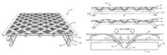
- FIG. 1is a perspective view of a mattress and foundation assembly in accordance with the present disclosure
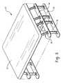
- FIG. 2is a perspective view of a mattress foundation in accordance with the present disclosure
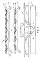
- FIG. 3provides side elevation views of the mattress foundation including the dual suspension layers with and without an applied load in accordance with the present disclosure
- FIG. 4is a top down plan view of the mattress foundation in accordance with the present disclosure.
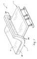
- FIG. 5is a silhouetted perspective view of the mattress foundation including a foam pad layer disposed on the upper suspension layer in accordance with the present disclosure
- FIG. 6is an exploded perspective view of the dual suspension layers including the foam pad layer of FIG. 5 ;
- FIG. 7is a perspective view of the mattress foundation assembly including the mattress having a recessed portion for placement onto the mattress foundation in accordance with the present disclosure.
- the mattress and foundation assembly 10generally includes a mattress 12 and a mattress foundation 14 including dual suspension layers.
- dual suspension layersboth soft support and firm support can be provided.
- the dual suspension layersconform to the user and reduce the various pressure points associated with the user while dissipating heat.
- the mattress foundation 14generally includes two spaced apart and rectangularly shaped mesh suspension layers 16 , 18 that are flexible and independently supported by frame 20 .
- the flexible mesh dual suspension layers 16 , 18are each supported at various contact points by numerous u-shaped carriers 22 , 24 , respectively, that are pivotably mounted to the frame 20 and define the relative height of each layer.
- U-shaped carriers 24support the upper suspension layer 18 at a defined height and u-shaped carriers 22 support the lower suspension layer 16 at a defined height that is less than that of the upper suspension layer 18 .
- the u-shaped carriers 22 , 24can pivotably move and effect a local or global change in the relative position of one or both of the dual suspension layers 16 , 18 in response to an applied force, e. g., the applied weight and/or pressure related to an individual and his movement on the mattress overlying the dual suspension layer.
- an applied forcee. g., the applied weight and/or pressure related to an individual and his movement on the mattress overlying the dual suspension layer.
- the dual suspension layer(s) at that particular mattress locationwould generally not flex.
- the distance between the suspension layers 16 , 18is generally configured to be in an amount effective to provide flexure to both layers should a predefined load be applied unequally across a u-shaped carrier when in use. In some embodiments, it may be desired to provide greater flexure to the upper suspension layer 18 than the lower suspension layer 16 so as to provide a soft upper suspension layer 18 and a firm lower suspension layer 16 .
- the amount of flexurecan generally be controlled by the choice of materials for the mesh suspension layers 16 , 18 as well as the degrees of rotational freedom permitted by the u-shaped carriers 22 , 24 .
- the mattress foundation 14 with the lower and upper mesh dual suspensions layers 16 , 18 , respectivelyprovides the mattress and foundation assembly 10 with improved airflow, optimal temperature management, counterbalanced comfort, and can be configured for any sized mattress.
- the assembly 10provides independent and individualized support of a body thereon at any pressure point regardless of body size, shape, and body movement.
- the mattress foundation assembly 10permits easy access to and provides storage underneath the foundation 14 .
- the mattress 12 of the mattress and foundation assembly 10can be configured to be removable as will be described below and may also be configured to provide an appearance approximating that of a conventional mattress of the type typically disposed on a conventional box spring, for example. In this manner, the user can utilize traditional sheeting and supplemental bedding products such as a mattress topper pad as may be desired.
- the mattress foundation frame 20generally includes a head end 26 , a foot end 28 , and at least one transverse support member 30 there between, two of which are depicted.
- the transverse members extending between the head and foot ends 26 , 28respectively, that generally correspond to the head and foot ends of a traditional mattress disposed thereon, it should be readily apparent that the frame could be oriented from side to side as opposed to from the depicted head end to foot end. However, maximum ease of underneath access is provided when the frame including the transverse members extends between the head and foot ends as is generally shown.
- Each head and foot end 26 , 28generally includes an optional base 32 for contacting the ground, a top support 34 spaced apart from the base 32 , and one or more vertical members 36 extending between the base 32 and the top support. 34 .
- the vertical memberscontact the ground directly and generally serve as leg supports for the top support 34 .
- the height of the top support 34can be configured to define the height at which the bottommost surface of the mattress 12 employed in the mattress foundation assembly 10 thereon is relative to ground.
- the transverse support members 30are attached to and extend between the top supports 34 of the head and foot ends 26 , 28 .
- the transverse support member 30includes a vertically oriented portion 38 extending from the top support 34 and a substantially horizontal portion 40 extending there between such that the substantially horizontal portion is at a height greater than the top support (see FIG. 3 ).
- the substantially horizontal portion 40 of the transverse member 30includes a plurality of spaced apart openings 42 , wherein the openings are configured to receive a rod inserted therein.
- the openings of the multiple transverse support members 30are coaxially aligned so as to permit a rod 44 to be inserted therein.
- the openings 42are spaced part about the horizontal portion of each transverse support members 30 at equal distances. In other embodiments, the openings 42 are spaced apart at unequal distances.
- the particular number and size of the openingsare in amount and of a dimension that are effective to provide structural rigidity upon assembly of the mattress foundation assembly and provide sufficient support when used in combination with the u-shaped carriers 22 , 24 and rods 44 .
- Each rod 44can be rotatably disposed within the coaxially aligned openings 42 between the transverse support members 30 , wherein the u-shaped carriers 22 , 24 are fixedly attached to the rods.
- the u-shaped carrierscan be rotatably attached to the rods, wherein the rods are non-rotatably attached to the transverse support members 30 .
- the number and location of the u-shaped carriers disposed on the rodcan vary but should be provide sufficient support to both suspension layers 16 , 18 and the mattress 12 of the mattress foundation assembly 10 when in use.
- the frame 20may further include additional bracing materials and the like as may be desired for different applications.
- the lower suspension layer 16includes a rigid frame 46 and a mesh 48 coextensive with the frame 46 defined by matrix having a plurality of openings.
- the mesh 48is flexible as well as elastic and is held relatively taut within the frame 46 .
- the particular pattern in the mesh 48is generally not intended to be limited provided at least some of the openings 48 in the lower suspension layer 16 are of a dimension and at a location effective to permit a portion of the u-shaped carrier 24 to extend through the openings so as to contact and support the upper suspension layer 18 .
- the lower suspension layer 16is attached to and supported by the u-shaped carriers 22 .
- the upper suspension layer 18includes a frame 50 and a mesh 52 coextensive with the frame 50 defined by matrix having a plurality of openings.
- the mesh 52is flexible as well as elastic and is held relatively taut within the frame 50 .
- the upper suspension layerdoes not require openings to accommodate the u-shaped carriers and in some embodiments, it may be desirable to have a continuous sheet without any openings. However, it is generally desirable to have at least some openings to enable and control airflow and to provide temperature management.
- the upper suspension layer 16is attached to and supported by the u-shaped carrier 24 .
- the terms “mesh”generally refers to a mesh material that is a continuous sheet in that it is essentially consistent in its composition of strands and intervening openings (although it may have a pattern therein) and essentially covers the entirety of the layer.
- the mesh material and framemay be of the same material or may be of a different material and is generally formed of a flexible and elastic material that readily deflects under the weight of a user upon pivot rotation of the u-shaped carrier and returns to its previous position after unloading (as opposed to an embossed metal or rigid screen, for example).
- the mesh materialcan be formed of an elastomer in whole or in part.
- the meshmay further include gels and phase change materials.
- the mesh materialcan include a polypropylene mesh fabric or the like.
- the meshcan be a woven mesh or a knitted mesh.
- the openings in the meshwhich may have the same or different sizes based on the pattern of the weave, can have substantially the same size, dimension or width of the strands, or be on the same order provided that in the lower suspension layer 16 there are at least some openings of a size and dimension effective to permit the u-shaped carriers 24 to contact the upper suspension layer 18 .
- Other types of mesh or compositions of strands with less or more elastomercan be used.
- the meshcan be woven or knitted.
- the meshcan be formed of flexible and elastic patterned open texture plastic.
- sheet of patterned open texture plasticis used herein to refer to a plastic material that has a series or arrangement of openings across the sheet and that is continuous within the frame.
- the sheet of plasticis flexible and elastic in that it readily deflects under the weight of a user and returns to its previous position after unloading (as opposed to an embossed metal or rigid screen).
- the sheet of plastic and the material of the sheet of plasticcan be selected so that the sheet of plastic can deflect or bend.
- the openingscan be sized and patterned to facilitate deflection or bending, and to eliminate pressure points.
- the openings and the material between the openingscan be substantially the same size, dimension or width, or on the same order as was previously described for the elastomeric materials.
- the mattress 12 for the mattress foundation assembly, 10is formed of at least one layer of a foam material and generally includes a planar top surface 60 , a bottom surface 62 , and sidewalls 64 extending between the top and bottom surfaces.
- the bottom surface 62includes a recessed portion 66 dimensioned to snugly fit about the perimeters of the optional foam padding layer 45 and mesh dual suspension layers 16 , 18 as shown.
- the depicted mattressmay be covered with a casing of upholstery for providing a proper aesthetic appearance. By configuring the mattress with a recessed portion, weight is minimized, thereby reducing transportation costs.
- the mattress 12can be removable and replaceable as can be optional foam padding layer 45 .
- Suitable foamsinclude, but are not limited to, polyurethane foams including synthetic, blended and natural polyurethane foams, latex foams including natural, blended and synthetic latex foams; polystyrene foams, polyethylene foams, polypropylene foam, polyether-polyurethane foams, and the like.
- the foamcan be selected to be viscoelastic or non-viscoelastic foams. Some viscoelastic materials are also temperature sensitive, thereby also enabling the convoluted foam layer to change shape based in part upon the temperature of the supported part. Any of these foams may be open celled or closed cell or a hybrid structure of open cell and closed cell.
- the foamscan be reticulated or partially reticulated or non-reticulated.
- the term reticulationgenerally refers to removal of cell membranes to create an open cell structure that is open to air and moisture flow.
- the foamsmay be gel infused in some embodiments, wherein gel is infused into at least some of the pores within the foam.
- the foamscan include phase change materials that are embedded or applied thereto.
- the different layerscan be formed of the same material configured with different properties or be formed of different materials.
- foams suitable for use in the mattress foundation assembly 10may be produced according to methods known to persons ordinarily skilled in the art.
- polyurethane foamsare typically prepared by reacting a polyol with a polyisocyanate in the presence of a catalyst, a blowing agent, one or more foam stabilizers or surfactants and other foaming aids.
- the gas generated during polymerizationcauses foaming of the reaction mixture to form a cellular or foam structure.
- Latex foamsare typically manufactured by the well known Dunlap or Talalay processes.
- the properties for the at least one foam layer defining the mattress 12are not intended to be limited.
- the hardness properties of foamare also referred to as the indention load deflection (ILD) or indention force deflection (IFD) and are measured in accordance with ASTM D-3574 and ASTM D-3575.
- the hardness of the foamcan have an indention load deflection (ILD) of about 7 to about 16 pounds force for viscoelastic foams and an ILD of about 7 to about 55 pounds force for non-viscoelastic foams.
- the density propertiesare a measurement of the mass per unit volume and can generally range from about 0.7 to about 2.5 pounds per cubic foot for non viscoelastic foams and about 1.5 to about 6 pounds per cubic foot for viscoelastic foams.
Landscapes
- Mattresses And Other Support Structures For Chairs And Beds (AREA)
Abstract
Description
Claims (22)
Priority Applications (1)
| Application Number | Priority Date | Filing Date | Title |
|---|---|---|---|
| US13/649,441US8813279B2 (en) | 2011-10-11 | 2012-10-11 | Mattresses and mattress foundations |
Applications Claiming Priority (2)
| Application Number | Priority Date | Filing Date | Title |
|---|---|---|---|
| US201161545795P | 2011-10-11 | 2011-10-11 | |
| US13/649,441US8813279B2 (en) | 2011-10-11 | 2012-10-11 | Mattresses and mattress foundations |
Publications (2)
| Publication Number | Publication Date |
|---|---|
| US20130086743A1 US20130086743A1 (en) | 2013-04-11 |
| US8813279B2true US8813279B2 (en) | 2014-08-26 |
Family
ID=48041096
Family Applications (1)
| Application Number | Title | Priority Date | Filing Date |
|---|---|---|---|
| US13/649,441Active2032-11-08US8813279B2 (en) | 2011-10-11 | 2012-10-11 | Mattresses and mattress foundations |
Country Status (1)
| Country | Link |
|---|---|
| US (1) | US8813279B2 (en) |
Cited By (5)
| Publication number | Priority date | Publication date | Assignee | Title |
|---|---|---|---|---|
| US20150216317A1 (en)* | 2014-01-31 | 2015-08-06 | Dreamwell, Ltd. | Mattress including flat springs |
| US9888782B1 (en)* | 2017-01-27 | 2018-02-13 | Eastern Sleep Products Company | Temperature controlled mattress system |
| US10989240B2 (en) | 2018-07-31 | 2021-04-27 | Larry Self | Bed frame designed for quick assembly |
| US20230309704A1 (en)* | 2022-03-31 | 2023-10-05 | Dreamwell, Ltd. | Adjustable firmness mattress assemblies |
| USD1024619S1 (en)* | 2020-10-07 | 2024-04-30 | Dreamwell, Ltd. | Mattress including mattress handles |
Families Citing this family (4)
| Publication number | Priority date | Publication date | Assignee | Title |
|---|---|---|---|---|
| WO2014194224A2 (en)* | 2013-05-30 | 2014-12-04 | Prime Medical, LLC | Operating room table pad |
| USD753935S1 (en)* | 2013-06-18 | 2016-04-19 | Marshall Ventilated Mattress Company Limited | Bed foundation |
| DE202013103212U1 (en)* | 2013-07-17 | 2013-09-18 | Lorenz Kunststofftechnik Gmbh | Spring strip bearing body of a slatted frame |
| US9474383B1 (en)* | 2014-09-12 | 2016-10-25 | Oddello Industries, Llc | Deck panel with airflow stimulation and moisture release elements |
Citations (15)
| Publication number | Priority date | Publication date | Assignee | Title |
|---|---|---|---|---|
| US134430A (en)* | 1872-12-31 | Improvement | ||
| US464604A (en)* | 1891-12-08 | Ozello k | ||
| US537847A (en)* | 1895-04-23 | Spring bed-bottom | ||
| US763442A (en)* | 1903-02-14 | 1904-06-28 | Frederick J Van Cise | Mattress-frame. |
| US795223A (en)* | 1904-10-11 | 1905-07-18 | Nathan P Rathbun | Bed-bottom. |
| US3119126A (en)* | 1962-03-06 | 1964-01-28 | Goodman Robert | Box spring assembly |
| US4112529A (en)* | 1977-06-20 | 1978-09-12 | The United States Bedding Company | Foundation unit for bedding |
| US4567615A (en)* | 1983-01-13 | 1986-02-04 | Matra Ag | Spring-slat arrangement for a bedstead |
| US4703526A (en)* | 1985-09-03 | 1987-11-03 | Marpal Ag | Undermattress using paired slats and an elastic supporting member |
| US5924149A (en)* | 1994-11-22 | 1999-07-20 | Weber; Erhard | Three-point bridge suspension end bearing triflex for transverse slats in bed underframes and uses thereof |
| US20020178498A1 (en)* | 2000-04-03 | 2002-12-05 | Florin Baeriswyl | Slatted frame for reclining furniture |
| US6584627B1 (en)* | 2002-01-16 | 2003-07-01 | Chen-Yen Yang | Webbed frame for furniture |
| US7003822B1 (en) | 2000-10-16 | 2006-02-28 | Extrutech Plastics, Inc. | Extruded knock-down plastic bed frame assembly |
| US7832040B2 (en) | 2007-01-24 | 2010-11-16 | Sealy Technology Llc | Suspended flexible matrix support system |
| US8191186B2 (en)* | 2005-04-27 | 2012-06-05 | Tournadre Sa Standard Gum | Device for the suspension of slats for a bed |
- 2012
- 2012-10-11USUS13/649,441patent/US8813279B2/enactiveActive
Patent Citations (16)
| Publication number | Priority date | Publication date | Assignee | Title |
|---|---|---|---|---|
| US134430A (en)* | 1872-12-31 | Improvement | ||
| US464604A (en)* | 1891-12-08 | Ozello k | ||
| US537847A (en)* | 1895-04-23 | Spring bed-bottom | ||
| US763442A (en)* | 1903-02-14 | 1904-06-28 | Frederick J Van Cise | Mattress-frame. |
| US795223A (en)* | 1904-10-11 | 1905-07-18 | Nathan P Rathbun | Bed-bottom. |
| US3119126A (en)* | 1962-03-06 | 1964-01-28 | Goodman Robert | Box spring assembly |
| US4112529A (en)* | 1977-06-20 | 1978-09-12 | The United States Bedding Company | Foundation unit for bedding |
| US4567615A (en)* | 1983-01-13 | 1986-02-04 | Matra Ag | Spring-slat arrangement for a bedstead |
| US4703526A (en)* | 1985-09-03 | 1987-11-03 | Marpal Ag | Undermattress using paired slats and an elastic supporting member |
| US5924149A (en)* | 1994-11-22 | 1999-07-20 | Weber; Erhard | Three-point bridge suspension end bearing triflex for transverse slats in bed underframes and uses thereof |
| US20020178498A1 (en)* | 2000-04-03 | 2002-12-05 | Florin Baeriswyl | Slatted frame for reclining furniture |
| US7003822B1 (en) | 2000-10-16 | 2006-02-28 | Extrutech Plastics, Inc. | Extruded knock-down plastic bed frame assembly |
| US6584627B1 (en)* | 2002-01-16 | 2003-07-01 | Chen-Yen Yang | Webbed frame for furniture |
| US20030131410A1 (en)* | 2002-01-16 | 2003-07-17 | Chen-Yen Yang | Webbed frame for furniture |
| US8191186B2 (en)* | 2005-04-27 | 2012-06-05 | Tournadre Sa Standard Gum | Device for the suspension of slats for a bed |
| US7832040B2 (en) | 2007-01-24 | 2010-11-16 | Sealy Technology Llc | Suspended flexible matrix support system |
Cited By (7)
| Publication number | Priority date | Publication date | Assignee | Title |
|---|---|---|---|---|
| US20150216317A1 (en)* | 2014-01-31 | 2015-08-06 | Dreamwell, Ltd. | Mattress including flat springs |
| US9901185B2 (en)* | 2014-01-31 | 2018-02-27 | Dreamwell, Ltd. | Mattress including flat springs |
| US9888782B1 (en)* | 2017-01-27 | 2018-02-13 | Eastern Sleep Products Company | Temperature controlled mattress system |
| US10989240B2 (en) | 2018-07-31 | 2021-04-27 | Larry Self | Bed frame designed for quick assembly |
| USD1024619S1 (en)* | 2020-10-07 | 2024-04-30 | Dreamwell, Ltd. | Mattress including mattress handles |
| US20230309704A1 (en)* | 2022-03-31 | 2023-10-05 | Dreamwell, Ltd. | Adjustable firmness mattress assemblies |
| US12239230B2 (en)* | 2022-03-31 | 2025-03-04 | Dreamwell, Ltd. | Adjustable firmness mattress assemblies |
Also Published As
| Publication number | Publication date |
|---|---|
| US20130086743A1 (en) | 2013-04-11 |
Similar Documents
| Publication | Publication Date | Title |
|---|---|---|
| US8813279B2 (en) | Mattresses and mattress foundations | |
| US11602227B2 (en) | Mattresses including spacer fabric and related methods | |
| US20210282571A1 (en) | Pocketed foam systems and methods | |
| US9119478B2 (en) | Dual-spring plunger for a plunger matrix mattress | |
| US8356372B2 (en) | Systems and methods for hinged bedding assemblies | |
| JP4912553B2 (en) | Bed structure with reduced deflection | |
| EP2185038B1 (en) | Improved cushioning apparatus | |
| US11825952B2 (en) | Ventilated comfort layer | |
| KR20250057141A (en) | Composite mattresses with air chambers | |
| US20190038043A1 (en) | Dual density systems and methods for bedding applications | |
| EP1670339A2 (en) | Mattress center ridge compensator | |
| EP4358800A1 (en) | Two-sided hybrid mattress topper | |
| US20110283461A1 (en) | Body support with non-planar top surface | |
| US20240251964A1 (en) | Elastomeric grid including discrete cushioning elements | |
| US20240130538A1 (en) | Cover for a body support cushion | |
| US20230210272A1 (en) | Removable mattress topper with vibrating units | |
| MXPA97000595A (en) | Mixed mattress and cover for mattress that has a foam unnucleo |
Legal Events
| Date | Code | Title | Description |
|---|---|---|---|
| AS | Assignment | Owner name:DREAMWELL, LTD., NEVADA Free format text:ASSIGNMENT OF ASSIGNORS INTEREST;ASSIGNORS:SAUNDERS, CRAIG;SPIRK, J. EVAN;TUFTS, LINDSEY;AND OTHERS;SIGNING DATES FROM 20121112 TO 20121114;REEL/FRAME:029378/0840 | |
| STCF | Information on status: patent grant | Free format text:PATENTED CASE | |
| AS | Assignment | Owner name:UBS AG, STAMFORD BRANCH, AS ADMINISTRATIVE AGENT, CONNECTICUT Free format text:FIRST LIEN TERM LOAN INTELLECTUAL PROPERTY SECURITY AGREEMENT;ASSIGNOR:DREAMWELL, LTD.;REEL/FRAME:040813/0136 Effective date:20161108 Owner name:GOLDMAN SACHS BANK USA, AS ADMINISTRATIVE AGENT, NEW YORK Free format text:SECOND LIEN TERM LOAN INTELLECTUAL PROPERTY SECURITY AGREEMENT;ASSIGNOR:DREAMWELL, LTD.;REEL/FRAME:040813/0175 Effective date:20161108 Owner name:UBS AG, STAMFORD BRANCH, AS ADMINISTRATIVE AGENT, CONNECTICUT Free format text:ABL INTELLECTUAL PROPERTY SECURITY AGREEMENT;ASSIGNOR:DREAMWELL, LTD.;REEL/FRAME:040813/0213 Effective date:20161108 Owner name:UBS AG, STAMFORD BRANCH, AS ADMINISTRATIVE AGENT, Free format text:FIRST LIEN TERM LOAN INTELLECTUAL PROPERTY SECURITY AGREEMENT;ASSIGNOR:DREAMWELL, LTD.;REEL/FRAME:040813/0136 Effective date:20161108 Owner name:GOLDMAN SACHS BANK USA, AS ADMINISTRATIVE AGENT, N Free format text:SECOND LIEN TERM LOAN INTELLECTUAL PROPERTY SECURITY AGREEMENT;ASSIGNOR:DREAMWELL, LTD.;REEL/FRAME:040813/0175 Effective date:20161108 Owner name:UBS AG, STAMFORD BRANCH, AS ADMINISTRATIVE AGENT, Free format text:ABL INTELLECTUAL PROPERTY SECURITY AGREEMENT;ASSIGNOR:DREAMWELL, LTD.;REEL/FRAME:040813/0213 Effective date:20161108 | |
| MAFP | Maintenance fee payment | Free format text:PAYMENT OF MAINTENANCE FEE, 4TH YEAR, LARGE ENTITY (ORIGINAL EVENT CODE: M1551) Year of fee payment:4 | |
| AS | Assignment | Owner name:UBS AG, STAMFORD BRANCH, AS ADMINISTRATIVE AGENT, CONNECTICUT Free format text:SUPER-PRIORITY TERM LOAN INTELLECTUAL PROPERTY SECURITY AGREEMENT;ASSIGNOR:DREAMWELL, LTD.;REEL/FRAME:053022/0029 Effective date:20200622 | |
| MAFP | Maintenance fee payment | Free format text:PAYMENT OF MAINTENANCE FEE, 8TH YEAR, LARGE ENTITY (ORIGINAL EVENT CODE: M1552); ENTITY STATUS OF PATENT OWNER: LARGE ENTITY Year of fee payment:8 | |
| AS | Assignment | Owner name:DREAMWELL, LTD., GEORGIA Free format text:RELEASE OF SECOND LIEN SECURITY INTEREST IN INTELLECTUAL PROPERTY RECORDED AT R/F 040813/1075;ASSIGNOR:GOLDMAN SACHS BANK USA, AS ADMINISTRATIVE AGENT;REEL/FRAME:059925/0322 Effective date:20220506 | |
| AS | Assignment | Owner name:ECLIPSE BUSINESS CAPITAL LLC, ILLINOIS Free format text:SECURITY INTEREST;ASSIGNORS:DREAMWELL, LTD.;SSB MANUFACTURING;NATIONAL BEDDING;AND OTHERS;REEL/FRAME:062525/0458 Effective date:20230125 | |
| AS | Assignment | Owner name:ECLIPSE BUSINESS CAPITAL LLC, ILLINOIS Free format text:SECURITY INTEREST;ASSIGNORS:DREAMWELL, LTD.;SSB MANUFACTURING;NATIONAL BEDDING;AND OTHERS;REEL/FRAME:062571/0391 Effective date:20230126 | |
| AS | Assignment | Owner name:WILMINGTON SAVINGS FUND SOCIETY, FSB, AS SUCCESSOR ADMINISTRATIVE AGENT, DELAWARE Free format text:NOTICE OF AGENCY RESIGNATION AND ASSIGNMENT OF SUPER-PRIORITY TERM LOAN INTELLECTUAL PROPERTY SECURITY AGREEMENT;ASSIGNOR:UBS AG, STAMFORD BRANCH, AS THE RESIGNING ADMINISTRATIVE AGENT;REEL/FRAME:063272/0391 Effective date:20230206 | |
| AS | Assignment | Owner name:TOMORROW SLEEP LLC, GEORGIA Free format text:RELEASE OF SUPER-PRIORITY SECURITY INTEREST IN INTELLECTUAL PROPERTY;ASSIGNOR:WILMINGTON SAVINGS FUND SOCIETY, FSB, AS ADMINISTRATIVE AGENT;REEL/FRAME:064185/0479 Effective date:20230629 Owner name:TUFT & NEEDLE, LLC, GEORGIA Free format text:RELEASE OF SUPER-PRIORITY SECURITY INTEREST IN INTELLECTUAL PROPERTY;ASSIGNOR:WILMINGTON SAVINGS FUND SOCIETY, FSB, AS ADMINISTRATIVE AGENT;REEL/FRAME:064185/0479 Effective date:20230629 Owner name:SERTA SIMMONS BEDDING, LLC, GEORGIA Free format text:RELEASE OF SUPER-PRIORITY SECURITY INTEREST IN INTELLECTUAL PROPERTY;ASSIGNOR:WILMINGTON SAVINGS FUND SOCIETY, FSB, AS ADMINISTRATIVE AGENT;REEL/FRAME:064185/0479 Effective date:20230629 Owner name:NATIONAL BEDDING COMPANY, L.L.C., GEORGIA Free format text:RELEASE OF SUPER-PRIORITY SECURITY INTEREST IN INTELLECTUAL PROPERTY;ASSIGNOR:WILMINGTON SAVINGS FUND SOCIETY, FSB, AS ADMINISTRATIVE AGENT;REEL/FRAME:064185/0479 Effective date:20230629 Owner name:SSB MANUFACTURING COMPANY, GEORGIA Free format text:RELEASE OF SUPER-PRIORITY SECURITY INTEREST IN INTELLECTUAL PROPERTY;ASSIGNOR:WILMINGTON SAVINGS FUND SOCIETY, FSB, AS ADMINISTRATIVE AGENT;REEL/FRAME:064185/0479 Effective date:20230629 Owner name:DREAMWELL, LTD., GEORGIA Free format text:RELEASE OF SUPER-PRIORITY SECURITY INTEREST IN INTELLECTUAL PROPERTY;ASSIGNOR:WILMINGTON SAVINGS FUND SOCIETY, FSB, AS ADMINISTRATIVE AGENT;REEL/FRAME:064185/0479 Effective date:20230629 Owner name:WILMINGTON SAVINGS FUND SOCIETY, FSB, AS ADMINISTRATIVE AGENT, DELAWARE Free format text:TERM LOAN INTELLECTUAL PROPERTY SECURITY AGREEMENT;ASSIGNORS:DREAMWELL, LTD.;TUFT & NEEDLE, LLC;SERTA SIMMONS BEDDING, LLC;AND OTHERS;REEL/FRAME:064185/0583 Effective date:20230629 Owner name:NATIONAL BEDDING COMPANY, L.L.C., GEORGIA Free format text:RELEASE OF FIRST LIEN SECURITY INTEREST IN INTELLECTUAL PROPERTY;ASSIGNOR:UBS AG, STAMFORD BRANCH, AS ADMINISTRATIVE AGENT;REEL/FRAME:064185/0293 Effective date:20230629 Owner name:SSB MANUFACTURING COMPANY, GEORGIA Free format text:RELEASE OF FIRST LIEN SECURITY INTEREST IN INTELLECTUAL PROPERTY;ASSIGNOR:UBS AG, STAMFORD BRANCH, AS ADMINISTRATIVE AGENT;REEL/FRAME:064185/0293 Effective date:20230629 Owner name:DREAMWELL, LTD., GEORGIA Free format text:RELEASE OF FIRST LIEN SECURITY INTEREST IN INTELLECTUAL PROPERTY;ASSIGNOR:UBS AG, STAMFORD BRANCH, AS ADMINISTRATIVE AGENT;REEL/FRAME:064185/0293 Effective date:20230629 Owner name:TOMORROW SLEEP LLC, GEORGIA Free format text:RELEASE OF FIRST LIEN SECURITY INTEREST IN INTELLECTUAL PROPERTY;ASSIGNOR:ECLIPSE BUSINESS CAPITAL LLC, AS ADMINISTRATIVE AGENT;REEL/FRAME:064185/0236 Effective date:20230629 Owner name:TUFT & NEEDLE, LLC, GEORGIA Free format text:RELEASE OF FIRST LIEN SECURITY INTEREST IN INTELLECTUAL PROPERTY;ASSIGNOR:ECLIPSE BUSINESS CAPITAL LLC, AS ADMINISTRATIVE AGENT;REEL/FRAME:064185/0236 Effective date:20230629 Owner name:SERTA SIMMONS BEDDING, LLC, GEORGIA Free format text:RELEASE OF FIRST LIEN SECURITY INTEREST IN INTELLECTUAL PROPERTY;ASSIGNOR:ECLIPSE BUSINESS CAPITAL LLC, AS ADMINISTRATIVE AGENT;REEL/FRAME:064185/0236 Effective date:20230629 Owner name:NATIONAL BEDDING COMPANY L.L.C., GEORGIA Free format text:RELEASE OF FIRST LIEN SECURITY INTEREST IN INTELLECTUAL PROPERTY;ASSIGNOR:ECLIPSE BUSINESS CAPITAL LLC, AS ADMINISTRATIVE AGENT;REEL/FRAME:064185/0236 Effective date:20230629 Owner name:SSB MANUFACTURING COMPANY, GEORGIA Free format text:RELEASE OF FIRST LIEN SECURITY INTEREST IN INTELLECTUAL PROPERTY;ASSIGNOR:ECLIPSE BUSINESS CAPITAL LLC, AS ADMINISTRATIVE AGENT;REEL/FRAME:064185/0236 Effective date:20230629 Owner name:DREAMWELL, LTD., GEORGIA Free format text:RELEASE OF FIRST LIEN SECURITY INTEREST IN INTELLECTUAL PROPERTY;ASSIGNOR:ECLIPSE BUSINESS CAPITAL LLC, AS ADMINISTRATIVE AGENT;REEL/FRAME:064185/0236 Effective date:20230629 | |
| AS | Assignment | Owner name:WELLS FARGO BANK, NATIONAL ASSOCIATION, NEW YORK Free format text:SECURITY AGREEMENT;ASSIGNORS:DREAMWELL, LTD.;TUFT & NEEDLE, LLC;SERTA SIMMONS BEDDING, LLC;AND OTHERS;REEL/FRAME:064193/0668 Effective date:20230629 | |
| AS | Assignment | Owner name:WILMINGTON SAVINGS FUND SOCIETY, FSB, DELAWARE Free format text:TERM LOAN INTELLECTUAL PROPERTY SECURITY AGREEMENT;ASSIGNORS:DREAMWELL, LTD.;NATIONAL BEDDING COMPANY, L.L.C.;SERTA SIMMONS BEDDING, LLC;AND OTHERS;REEL/FRAME:067379/0782 Effective date:20240419 | |
| AS | Assignment | Owner name:ECLIPSE BUSINESS CAPITAL LLC, AS ADMINISTRATIVE AGENT, ILLINOIS Free format text:SECURITY INTEREST;ASSIGNORS:WELLS FARGO BANK, NATIONAL ASSOCIATION;NATIONAL BEDDING COMPANY, L.L.C.;SERTA SIMMONS BEDDING, LLC;AND OTHERS;REEL/FRAME:068325/0886 Effective date:20240724 |