US8812987B2 - Virtual multiple sided virtual rotatable user interface icon queue - Google Patents
Virtual multiple sided virtual rotatable user interface icon queueDownload PDFInfo
- Publication number
- US8812987B2 US8812987B2US13/681,011US201213681011AUS8812987B2US 8812987 B2US8812987 B2US 8812987B2US 201213681011 AUS201213681011 AUS 201213681011AUS 8812987 B2US8812987 B2US 8812987B2
- Authority
- US
- United States
- Prior art keywords
- warp
- widget
- tablet computer
- sides
- user
- Prior art date
- Legal status (The legal status is an assumption and is not a legal conclusion. Google has not performed a legal analysis and makes no representation as to the accuracy of the status listed.)
- Expired - Fee Related
Links
Images


Classifications
- A—HUMAN NECESSITIES
- A63—SPORTS; GAMES; AMUSEMENTS
- A63F—CARD, BOARD, OR ROULETTE GAMES; INDOOR GAMES USING SMALL MOVING PLAYING BODIES; VIDEO GAMES; GAMES NOT OTHERWISE PROVIDED FOR
- A63F13/00—Video games, i.e. games using an electronically generated display having two or more dimensions
- A63F13/20—Input arrangements for video game devices
- A63F13/21—Input arrangements for video game devices characterised by their sensors, purposes or types
- A63F13/214—Input arrangements for video game devices characterised by their sensors, purposes or types for locating contacts on a surface, e.g. floor mats or touch pads
- A63F13/2145—Input arrangements for video game devices characterised by their sensors, purposes or types for locating contacts on a surface, e.g. floor mats or touch pads the surface being also a display device, e.g. touch screens
- A—HUMAN NECESSITIES
- A63—SPORTS; GAMES; AMUSEMENTS
- A63F—CARD, BOARD, OR ROULETTE GAMES; INDOOR GAMES USING SMALL MOVING PLAYING BODIES; VIDEO GAMES; GAMES NOT OTHERWISE PROVIDED FOR
- A63F13/00—Video games, i.e. games using an electronically generated display having two or more dimensions
- A63F13/20—Input arrangements for video game devices
- A63F13/23—Input arrangements for video game devices for interfacing with the game device, e.g. specific interfaces between game controller and console
- A—HUMAN NECESSITIES
- A63—SPORTS; GAMES; AMUSEMENTS
- A63F—CARD, BOARD, OR ROULETTE GAMES; INDOOR GAMES USING SMALL MOVING PLAYING BODIES; VIDEO GAMES; GAMES NOT OTHERWISE PROVIDED FOR
- A63F13/00—Video games, i.e. games using an electronically generated display having two or more dimensions
- A63F13/20—Input arrangements for video game devices
- A63F13/24—Constructional details thereof, e.g. game controllers with detachable joystick handles
- A—HUMAN NECESSITIES
- A63—SPORTS; GAMES; AMUSEMENTS
- A63F—CARD, BOARD, OR ROULETTE GAMES; INDOOR GAMES USING SMALL MOVING PLAYING BODIES; VIDEO GAMES; GAMES NOT OTHERWISE PROVIDED FOR
- A63F13/00—Video games, i.e. games using an electronically generated display having two or more dimensions
- A63F13/30—Interconnection arrangements between game servers and game devices; Interconnection arrangements between game devices; Interconnection arrangements between game servers
- A63F13/31—Communication aspects specific to video games, e.g. between several handheld game devices at close range
- A—HUMAN NECESSITIES
- A63—SPORTS; GAMES; AMUSEMENTS
- A63F—CARD, BOARD, OR ROULETTE GAMES; INDOOR GAMES USING SMALL MOVING PLAYING BODIES; VIDEO GAMES; GAMES NOT OTHERWISE PROVIDED FOR
- A63F13/00—Video games, i.e. games using an electronically generated display having two or more dimensions
- A63F13/40—Processing input control signals of video game devices, e.g. signals generated by the player or derived from the environment
- A63F13/42—Processing input control signals of video game devices, e.g. signals generated by the player or derived from the environment by mapping the input signals into game commands, e.g. mapping the displacement of a stylus on a touch screen to the steering angle of a virtual vehicle
- A63F13/426—Processing input control signals of video game devices, e.g. signals generated by the player or derived from the environment by mapping the input signals into game commands, e.g. mapping the displacement of a stylus on a touch screen to the steering angle of a virtual vehicle involving on-screen location information, e.g. screen coordinates of an area at which the player is aiming with a light gun
- A—HUMAN NECESSITIES
- A63—SPORTS; GAMES; AMUSEMENTS
- A63F—CARD, BOARD, OR ROULETTE GAMES; INDOOR GAMES USING SMALL MOVING PLAYING BODIES; VIDEO GAMES; GAMES NOT OTHERWISE PROVIDED FOR
- A63F13/00—Video games, i.e. games using an electronically generated display having two or more dimensions
- A63F13/50—Controlling the output signals based on the game progress
- A63F13/53—Controlling the output signals based on the game progress involving additional visual information provided to the game scene, e.g. by overlay to simulate a head-up display [HUD] or displaying a laser sight in a shooting game
- A63F13/533—Controlling the output signals based on the game progress involving additional visual information provided to the game scene, e.g. by overlay to simulate a head-up display [HUD] or displaying a laser sight in a shooting game for prompting the player, e.g. by displaying a game menu
- A—HUMAN NECESSITIES
- A63—SPORTS; GAMES; AMUSEMENTS
- A63F—CARD, BOARD, OR ROULETTE GAMES; INDOOR GAMES USING SMALL MOVING PLAYING BODIES; VIDEO GAMES; GAMES NOT OTHERWISE PROVIDED FOR
- A63F13/00—Video games, i.e. games using an electronically generated display having two or more dimensions
- A63F13/90—Constructional details or arrangements of video game devices not provided for in groups A63F13/20 or A63F13/25, e.g. housing, wiring, connections or cabinets
- A63F13/92—Video game devices specially adapted to be hand-held while playing
- G—PHYSICS
- G06—COMPUTING OR CALCULATING; COUNTING
- G06F—ELECTRIC DIGITAL DATA PROCESSING
- G06F3/00—Input arrangements for transferring data to be processed into a form capable of being handled by the computer; Output arrangements for transferring data from processing unit to output unit, e.g. interface arrangements
- G06F3/01—Input arrangements or combined input and output arrangements for interaction between user and computer
- G06F3/048—Interaction techniques based on graphical user interfaces [GUI]
- G06F3/0481—Interaction techniques based on graphical user interfaces [GUI] based on specific properties of the displayed interaction object or a metaphor-based environment, e.g. interaction with desktop elements like windows or icons, or assisted by a cursor's changing behaviour or appearance
- G06F3/04817—Interaction techniques based on graphical user interfaces [GUI] based on specific properties of the displayed interaction object or a metaphor-based environment, e.g. interaction with desktop elements like windows or icons, or assisted by a cursor's changing behaviour or appearance using icons
- A—HUMAN NECESSITIES
- A63—SPORTS; GAMES; AMUSEMENTS
- A63F—CARD, BOARD, OR ROULETTE GAMES; INDOOR GAMES USING SMALL MOVING PLAYING BODIES; VIDEO GAMES; GAMES NOT OTHERWISE PROVIDED FOR
- A63F2300/00—Features of games using an electronically generated display having two or more dimensions, e.g. on a television screen, showing representations related to the game
- A63F2300/10—Features of games using an electronically generated display having two or more dimensions, e.g. on a television screen, showing representations related to the game characterized by input arrangements for converting player-generated signals into game device control signals
- A63F2300/1025—Features of games using an electronically generated display having two or more dimensions, e.g. on a television screen, showing representations related to the game characterized by input arrangements for converting player-generated signals into game device control signals details of the interface with the game device, e.g. USB version detection
- A—HUMAN NECESSITIES
- A63—SPORTS; GAMES; AMUSEMENTS
- A63F—CARD, BOARD, OR ROULETTE GAMES; INDOOR GAMES USING SMALL MOVING PLAYING BODIES; VIDEO GAMES; GAMES NOT OTHERWISE PROVIDED FOR
- A63F2300/00—Features of games using an electronically generated display having two or more dimensions, e.g. on a television screen, showing representations related to the game
- A63F2300/10—Features of games using an electronically generated display having two or more dimensions, e.g. on a television screen, showing representations related to the game characterized by input arrangements for converting player-generated signals into game device control signals
- A63F2300/1043—Features of games using an electronically generated display having two or more dimensions, e.g. on a television screen, showing representations related to the game characterized by input arrangements for converting player-generated signals into game device control signals being characterized by constructional details
- A—HUMAN NECESSITIES
- A63—SPORTS; GAMES; AMUSEMENTS
- A63F—CARD, BOARD, OR ROULETTE GAMES; INDOOR GAMES USING SMALL MOVING PLAYING BODIES; VIDEO GAMES; GAMES NOT OTHERWISE PROVIDED FOR
- A63F2300/00—Features of games using an electronically generated display having two or more dimensions, e.g. on a television screen, showing representations related to the game
- A63F2300/10—Features of games using an electronically generated display having two or more dimensions, e.g. on a television screen, showing representations related to the game characterized by input arrangements for converting player-generated signals into game device control signals
- A63F2300/1068—Features of games using an electronically generated display having two or more dimensions, e.g. on a television screen, showing representations related to the game characterized by input arrangements for converting player-generated signals into game device control signals being specially adapted to detect the point of contact of the player on a surface, e.g. floor mat, touch pad
- A63F2300/1075—Features of games using an electronically generated display having two or more dimensions, e.g. on a television screen, showing representations related to the game characterized by input arrangements for converting player-generated signals into game device control signals being specially adapted to detect the point of contact of the player on a surface, e.g. floor mat, touch pad using a touch screen
- A—HUMAN NECESSITIES
- A63—SPORTS; GAMES; AMUSEMENTS
- A63F—CARD, BOARD, OR ROULETTE GAMES; INDOOR GAMES USING SMALL MOVING PLAYING BODIES; VIDEO GAMES; GAMES NOT OTHERWISE PROVIDED FOR
- A63F2300/00—Features of games using an electronically generated display having two or more dimensions, e.g. on a television screen, showing representations related to the game
- A63F2300/20—Features of games using an electronically generated display having two or more dimensions, e.g. on a television screen, showing representations related to the game characterised by details of the game platform
- A63F2300/204—Features of games using an electronically generated display having two or more dimensions, e.g. on a television screen, showing representations related to the game characterised by details of the game platform the platform being a handheld device
- A—HUMAN NECESSITIES
- A63—SPORTS; GAMES; AMUSEMENTS
- A63F—CARD, BOARD, OR ROULETTE GAMES; INDOOR GAMES USING SMALL MOVING PLAYING BODIES; VIDEO GAMES; GAMES NOT OTHERWISE PROVIDED FOR
- A63F2300/00—Features of games using an electronically generated display having two or more dimensions, e.g. on a television screen, showing representations related to the game
- A63F2300/30—Features of games using an electronically generated display having two or more dimensions, e.g. on a television screen, showing representations related to the game characterized by output arrangements for receiving control signals generated by the game device
- A63F2300/308—Details of the user interface
- A—HUMAN NECESSITIES
- A63—SPORTS; GAMES; AMUSEMENTS
- A63F—CARD, BOARD, OR ROULETTE GAMES; INDOOR GAMES USING SMALL MOVING PLAYING BODIES; VIDEO GAMES; GAMES NOT OTHERWISE PROVIDED FOR
- A63F2300/00—Features of games using an electronically generated display having two or more dimensions, e.g. on a television screen, showing representations related to the game
- A63F2300/40—Features of games using an electronically generated display having two or more dimensions, e.g. on a television screen, showing representations related to the game characterised by details of platform network
- A63F2300/402—Communication between platforms, i.e. physical link to protocol
Definitions
- an apparatusin a preferred embodiment includes a tablet computer, the tablet computer preferably providing a plurality of sides, each of the plurality of sides are disposed between an electronic display screen and a back of the tablet computer, and an electronic game communicating with the tablet computer.
- the electronic gamepreferably provides an object displayed on the electronic display screen of the tablet computer, and movement of the object is controlled by an input device.
- the input deviceincludes at least a pair of side structures, one of the pair of side structures is adjacent to and confines the tablet computer on a first side of the plurality of sides of the tablet computer, the second side structure of the pair of side structures is adjacent to and confines the tablet computer on a second side of the plurality of sides of the tablet computer, wherein the first and second sides of the plurality of sides of the tablet computer are opposing sides of the plurality of sides of the tablet computer.
- the input devicefurther preferably includes a plurality of input switches, wherein the input switches are adjacent each of the at least two opposing sides of the plurality of sides of the tablet computer, and a bridge structure disposed between the pair of side structures and adjacent a third side of the plurality of sides of the tablet computer.
- the bridge structure in combination with the pair side structuresform a three sided structure in which the tablet computer nests such that the tablet computer is confined by the three sided structure, and the three sided structure mitigates inadvertent removal of the tablet computer from the three sided structure when the tablet computer is fully nested within the three sided structure.
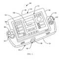
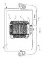
- FIG. 1is a front perspective view, with partial cutaway, of an embodiment an electronic game control apparatus constructed and operated in accordance with various embodiments disclosed and claimed herein.
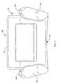
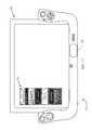
- FIG. 2shows a back plan view of the apparatus of FIG. 1 .
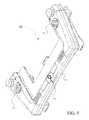
- FIG. 3displays a right side plan view, with partial cutaway, of the apparatus of FIG. 1 , constructed in accordance with various embodiments disclosed and claimed herein.
- FIG. 4depicts a right side plan view of the apparatus of FIG. 1 , constructed in accordance with various embodiments disclosed and claimed herein.
- FIG. 5illustrates a top perspective view of an embodiment of an input device of FIG. 1 , constructed in accordance with various embodiments disclosed and claimed herein.
- FIG. 6is a block diagram of an embodiment of the apparatus of FIG. 1 .
- FIG. 7is a block diagram of an alternate embodiment of the apparatus of FIG. 1 .
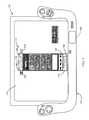
- FIG. 8shows an embodiment of a virtual multiple sided virtual rotatable user interface icon queue computer application (“warp widget”) displayed on an electronic display screen of the apparatus of FIG. 1 .
- warp widgetvirtual multiple sided virtual rotatable user interface icon queue computer application
- FIG. 9depicts the warp widget of FIG. 8 in an expanded, populated maintenance mode.
- FIG. 10shows the warp widget of FIG. 9 in a more detailed expanded, populated maintenance mode.
- FIG. 11shows the warp widget of FIG. 8 in an expanded, non-populated, operating mode.
- FIG. 12illustrates the warp widget of FIG. 10 in an expanded, populated, operating mode.
- FIG. 13displays an alternate, populated warp widget.
- FIG. 14shows the warp widget of FIG. 13 in an expanded, populated, operating mode.
- FIG. 15presents the warp widget of FIG. 14 in virtual rotation.
- FIG. 16shows the warp widget of FIG. 12 in a maintenance mode, and the tablet computer in a phone interactive mode.
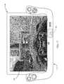
- FIG. 17illustrates the warp widget of FIG. 12 in a video game playing mode.
- FIG. 18displays the warp widget of FIG. 17 in an alternate video game mode the response of the system to an incoming phone call during game play.
- FIG. 19shows an alternate presentation of a virtual multiple sided virtual rotatable user interface icon queue computer application, wherein the presentation of the application takes the form of a four dimensional figure made up of eight 3-dimensional cubes and depicted in two dimensions.
- FIG. 20presents the warp widget of FIG. 8 with an auxiliary display module presenting a selection of operating modes to the user.
- FIG. 21presents the warp widget of FIG. 20 with an auxiliary display module presenting the TV control mode selected by the user.
- FIG. 22presents the warp widget of FIG. 21 with an auxiliary display module presenting the audio controls based on a selection by the user of the volume mode of FIG. 21 selected by the user.
- FIG. 23presents the warp widget of FIG. 21 with an auxiliary display module presenting the channel controls based on a selection by the user of the channel mode of FIG. 21 selected by the user.
- the present disclosuregenerally relates to an apparatus directed to controlling electronic games, also referred to herein as video games, or computer games.
- the apparatuspreferably includes a tablet computer, an electronic game communicating with the tablet computer, and an input device for controlling movement of a virtual object provided by the electronic game.
- the input deviceincludes a pair of opposing side structures adjacent opposing sides of plurality of sides of the tablet computer.
- the input devicefurther preferably includes a plurality of input switches, wherein said input switches are adjacent each of the at least two opposing sides of the plurality of sides of the tablet computer, and a bridge structure disposed between the pair of sides to form a three sided structure.
- the third structuremitigates inadvertent removal of the tablet computer from the three sided structure when the tablet computer is fully nested within the three sided structure.
- FIG. 1provides an exemplary game controller 100 capable of being used in accordance with various embodiments of the present invention.
- the exemplary game controller 100has at least a tablet computer 102 that providing a plurality of sides, such as 104 , 106 , 108 , and 126 . Each of the plurality of sides 104 , 106 , and 108 are disposed between an electronic display screen 110 , of the tablet computer 102 , and a back 112 (shown by FIG. 2 ) of the tablet computer 102 operates.
- the exemplary game controller 100further preferably includes an input device 114 .
- the input device 114provides a pair of side structures, 116 and 118 .
- One of the pair of side structures, for example 116is adjacent to and confines the tablet computer 102 on a first side, such as 104 of the plurality of sides 104 , 106 , 108 , and 126 of the tablet computer 102 .
- the second side structure of the pair of side structuresis adjacent to and confines the tablet computer 102 on a second side, such as 108 , of the plurality of sides 104 , 106 , 108 , and 126 of the tablet computer 102 , wherein the first and second sides, such as 104 and 108 , of the plurality of sides 104 , 106 , 108 , and 126 of the tablet computer 102 are opposing sides of the plurality of sides 104 , 106 , 108 , and 126 , of the tablet computer 102 .
- the input device 114further provides a plurality of input switches 120 and 122 , wherein the input switches 120 and 122 are adjacent each of the at least two opposing sides 104 and 108 , of the plurality of sides 104 , 106 , 108 , and 126 , of the tablet computer 102 , and a bridge structure 124 , disposed between the pair of side structures 116 and 118 , and adjacent the third side 126 , of the plurality of sides 104 , 106 , 108 , and 126 , of the tablet computer 102 .
- the bridge structure 124in combination with the pair of side structures 116 and 118 form a three sided structure 128 (of FIG.
- a u-shaped structure 128 of the input device 114(also referred to herein as a u-shaped structure 128 of the input device 114 ), in which the tablet computer 102 nests, such that the tablet computer 102 is confined by the u-shaped structure 128 , and the u-shaped structure 128 mitigates inadvertent removal of the tablet computer 102 from the u-shaped structure 128 when the tablet computer 102 is fully nested within the three sided structure 128 .
- the exemplary game controller 100 of FIG. 1further preferably includes a video game 130 .
- the video game 130provides a virtual object 132 displayed by the electronic display screen 110 , the virtual object 132 is responsive to input from the input device 114 .
- An example of a response of the virtual object 132would be movement of the virtual object 132 , or the loading of an alternate computer game, based on a predetermined signal provided by the input device 114 , or an appearance of a character.
- FIG. 1displays the housings of the plurality of switches, whereas at least some of the plurality of switches are shown in the partial cutaway of FIG. 3 .
- FIG. 2depicts the, and reveals the back 112 of the tablet computer 102 . Further shown by FIG. 2 , is the input device 114 , which provides a pair of trigger switches 136 and 138 , supported by their corresponding side structures 116 and 118 respectively.
- FIG. 3shows that a predetermined number of the plurality of switches 140 , collaborate with each other to form an input apparatus 142 , the input apparatus 142 controls display of virtual objects displayed on the electronic display screen 110 of the tablet computer 102 .
- the input apparatus 142is a joystick 142 .
- FIG. 3further shows that the input device 114 provides a plurality of buttons 144 and 120 which activate corresponding switches 145 and 121 .
- the main function of the trigger 138 , the joystick 142 , and the buttons 144 and 120is to govern the movement/actions of a playable body/object or otherwise influence events in a video game 130 (of FIG. 1 ) or an alternate computer game.
- FIG. 4shows the exemplary game controller 100 , further includes a second joystick 146 , and a second button 148 , which are provided on the side structure 116 , adjacent trigger 136 .
- FIG. 5shows the central processing unit (CPU) 150 , of the input device 114 .
- CPUcentral processing unit
- FIG. 6shows the input device 114 includes the CPU 150 , interacting with the plurality of switches 152 , which preferably include at least switches 120 , 122 , 136 , 138 , 142 , 144 , 146 , and 148 .
- FIG. 6further shows the input device 114 further includes a communications protocol 154 providing the communication link between the tablet computer 102 , and the input device 114 .
- a Universal Serial Bus (USB) communications protocolis utilized.
- the communications protocol 154is not limited to a USB protocol.
- the input device 114further incorporates Bluetooth Protocol Stack communications implementation, for enhanced device communications.
- FIG. 6further shows that the tablet computer 102 preferably includes at least a CPU 156 , interacting with the electronic display screen 110 , the video game 130 , a device driver 158 , which facilitates the interaction between the tablet computer 102 and the input device 114 , and a communications protocol 160 providing the communication link between the tablet computer 102 , and the input device 114 .
- a Universal Serial Bus (USB) communications protocolis utilized.
- USBUniversal Serial Bus
- the communications protocol 160is not limited to a USB protocol.
- the tablet computer 102further incorporates Bluetooth Protocol Stack communications implementation, for enhanced device communications.
- FIG. 7shows an alternative embodiment of an exemplary game controller 162 , in which the device driver 158 and the video game 130 are located in the input device 114 .
- FIG. 8shows an embodiment of a virtual multiple sided virtual rotatable user interface icon queue computer application 170 , also referred to herein as a warp widget 170 .
- the warp widget 170is configured for display on the electronic display screen 110 , or portion thereof, of the tablet computer 102 .
- the warp widget 170as shown by FIG. 8 , is presented in a non-active, unpopulated, retracted mode, and displays a side 172 of the virtual multiple sides of the plurality of sides.
- Each side 172 of the virtual multiple sidespresents a plurality of cells 174 , and a maintenance button 176 .
- each cell 174provides a portal that displays a predetermined application icon, such as 178 of FIG. 12 .
- Each cell 174further responds, to an activation request of the user, by activating a computer application associated with the predetermined application icon 178 presented by a cell 174 of a front facing side 172 , when said warp widget 170 is displayed in an expanded, populated, active mode as shown by FIG. 12 .
- the warp widget 170appears, during virtual rotation, to have six sides.
- the warp widget 170is configured to sequentially display as many sides 172 as needed to accommodate as many cells 174 as needed to house individual application icons 178 of the warp widget 170 .
- six cells 174are provided per side 172 , but the number of sides 172 presented could be more or fewer than six cells 174 presented pre side 172 as shown in FIGS. 10 and 11 .
- the warp widget 170is displayed in a home position 180 , on the electronic display screen 110 .
- the home position 180may be relocated to any area of the electronic display screen 110 by dragging and dropping the warp widget 170 .
- the response of the warp widget 170 to activation by a userdepends on where on the displayed side 172 the user interacts with the warp widget 170 .
- such an activationoccurs with a tap on the electronic display screen 110 (when the electronic display screen 110 is a touch screen), but may occur by clicking a mouse button, or tapping an auxiliary display module 182 (ADM 182 ), which when selected to function as a mouse touch pad, controls a pointer tool displayed on the electronic display screen 110 .
- ADM 182auxiliary display module 182
- the ADM 182is an auxiliary electronic display screen with at least the functionality of the electronic display screen 110 .
- the simultaneous activation of the trigger switches 136 and 138 of FIG. 4serve to turn on the ADM 182 .
- the useris presented with at least the options of selecting the ADM 182 to serve as a mouse pad in the foreground, and a data presentation display in the background; an interactive television volume and channel selection control in the background, and a mouse pad in the foreground; or as a text messaging window in the background and a mouse pad in the foreground, as shown by FIG. 20 .
- the ADM 182when selecting the mouse mode, is configured to control the response of a pointer tool on the electronic display screen 110 , and to interact with any paired Bluetooth device, such as a cell phone, by presenting information provided by the paired device such as, but not limited to, notification of a pending incoming call, the receipt of a text message, voice mail, or a tweet, while the user is occupied playing a video game, such as that shown by FIG. 17 , or downloading a new application, video game, media content link, or recording an event.
- a paired Bluetooth devicesuch as a cell phone
- the ADM 182is configured to control the response of a pointer tool on a screen of the TV, and to interact with the TV by providing at least a volume control feature 173 and channel selection navigation tool 175 , as shown by FIG. 21 .
- each the volume control feature 173 and channel selection navigation tool 175includes activation buttons 177 and 179 respectfully.
- the mouse pad featuresare suspended, a volume control screen appears, as shown by FIG. 22 , and the user can adjust the audio output of the TV.
- the audio output of the TVis at a desired level, the user taps the done button of the volume control feature 173 , and the mouse pad function is re-activated and the volume control feature 173 is deactivated.
- the mouse pad featuresare suspended and the user can select an alternate channel of the TV by interacting with the channel selection screen 169 shown by FIG. 23 .
- a channel display 167shows the channel selected by the user, if the channel is not the channel desired by the user, the user may tap the cancel button 165 . If however the channel display 167 displays the desired channel, the user may tap the enter button 163 , and when the TV is at a desired channel, the user taps the done button 161 , and the mouse pad function is re-activated and the channel selection navigation tool 175 is deactivated.
- volume control feature 173 and channel selection navigation tool 175are deactivated, they continue to appear in the background of the activated mouse pad. In a preferred embodiment, when the mouse pad is active in the foreground, the mouse pad is fully functional.
- the caller identification information(when available) is displayed, as shown by FIG. 18 .
- the userelects to answer the incoming call, by tapping the ADM 182 of FIG. 18 , the activity engaged in by the user (in this example; playing a video game) is suspended, and a microphone 181 , and a speaker 183 of FIG. 16 , are activated, unless the user has a headset or ear piece microphone and speaker device interacting with the tablet computer 102 , or the input device 114 , in which case the user utilizes the headset or ear piece microphone and speaker device to interact with the caller.
- the caller informationwill remain on the ADM 182 after the caller has ended the call on their end, and remain available to the user.
- the systemresponds by reverting to a maintenance mode presentation of the warp widget 170 and a presentation of a dialing pad 185 , a contacts navigation feature 187 , and a contacts list 189 , as shown by FIG. 16 .
- the contacts list 189has highlighted the source of the last incoming call (which in this example is Jean Johnson). With the source of the last incoming call highlighted, the user need only tap the enter key of the dialing pad 185 to return the call.
- the contacts navigation tool 187is useful in navigating to alphabetized contact lists 189 , which can be displayed by scrolling to a desired letter of the alphabet.
- the contacts list 189is useful in selecting a particular contact of interest by scrolling to the desired contact within the contact list 189 . By tapping on a selected contact of interest, that selected contact is highlighted in the contact list 189 , and by tapping, or clicking on the enter key of the dialing pad 185 , a call will be placed to the selected contact within the contact list.
- the paired devicewhen a cell phone is paired to either the tablet computer 102 , or the input device 114 , the paired device is automatically placed into the warp widget 170 and an application icon, as shown by sign number 191 .
- the paired phone application icon 191is activated, by tapping or clicking on the application icon 191 , the dialing pad 185 , the contacts navigation feature 187 , and a contacts list 189 , appear on the electronic display screen 110 , as shown by FIG. 16 , which function as described hereinabove.
- maneuvering of the joystick 142 and an activation of either predetermined trigger switch 136 or 138 of FIG. 4functions as an activation technique for activating the warp widget 170 .
- the joystick 142serves to maneuver a pointer tool displayed on the electronic display screen 110
- the trigger switch 138serves as the right mouse button while the trigger switch 136 serves as the right mouse button.
- the warp widget 170responds by shifting to an expanded, unpopulated, active mode, as shown by FIG. 11 , or to an expanded, populated, active mode, as shown by FIG. 12 .
- the expanded, unpopulated, active mode, of the warp widget 170 as shown by FIG. 11is the result of an activation of a retracted, unpopulated, inactive warp widget 170 as shown by FIG. 8 .
- the expanded, populated, active mode, of the warp widget 170 as shown by FIG. 12is the result of an activation of a retracted, populated, inactive warp widget 170 as shown by FIG. 12 .
- the maintenance button 176when the warp widget 170 is in the expanded, (either populated or unpopulated), active mode as shown by FIGS. 11 and 12 , the maintenance button 176 , of FIGS. 8 and 13 , is unavailable to the user.
- the warp widgetwhen the warp widget is in the expanded, (either populated or unpopulated), active mode as shown by FIGS. 11 and 12 , the maintenance button 176 , of FIGS. 8 and 13 , is made available to the user.
- the warp widget 170moves to an alternate position on the electronic display screen 110 ; presents a navigation window 184 ; activates a warp widget spawning button 186 (also referred to herein as the WW button 186 ) of the maintenance button 176 ; populates a status window 188 of the maintenance button 176 ; presents a population button 190 that includes an internet connection condition indicator 192 ; and displays warp widget type indicators 194 and 196 , all shown by FIG. 9 .
- the userwhen the status window 188 is populated, the user is informed of two things. First, which side 172 of the plurality of sides is being presented, and second that maintenance tasks may be performed on the warp widget 170 . Additionally in the preferred embodiment, when the internet connection condition indicator 192 is present, the user is being informed that the warp widget 170 has established access to the internet.
- the warp widget type indicator 194is in force (which identifies the warp widget as an infinity sided warp widget 170 ), or the warp widget type indicator 196 is in force (which identifies the warp widget as a six sided warp widget 170 ).
- the warp widget typeis the infinity sided warp widget 170
- the warp widget 170upon populating the initially available thirty six cells 174 of the warp widget 170 , the warp widget 170 generates an additional side with, preferably, six additional cells 174 and updates the status window 188 showing the total number of sides of the warp widget 170 .
- application iconmeans at least a graphical representation of a launcher, which upon activation launches whatever application, device, media source (TV, radio, videos, etc.), content, cloud, or communication port associated with the application icon 178 .
- the warp widget 170When the warp widget type is the six sided warp widget 170 , and upon populating thirty five of the initially available thirty six cells 174 of the warp widget 170 , the warp widget 170 generates an additional, or child warp widget 170 with, preferably, six additional sides 172 , with each side providing six cells 174 .
- the warp widget 170further preferably populates the last cell 174 of the last side 172 of the parent warp widget with the newly generated child warp widget 170 , and identifies the presence of two warp widgets associated with the parent warp widget 170 by updating the number of warp widgets associated with the parent warp widget, and displaying total number of warp widgets in the WW button 186 .
- This procedurecontinues for as many application icons 178 the user chooses to place within the warp widget 170 .
- the userhas the option of adding an additional warp widget by tapping the WW button 186 .
- the warp widget 170is a six sided warp widget type, or an infinity type warp widget
- the usercan select, at any time, which type they prefer.
- the defaultis a six sided, warp widget type, but may be switched to an infinity type warp widget by pressing the warp widget type indicator 194 .
- the warp widget 170is in the infinity type warp widget mode, the user may switch it to a six sided warp widget type by pressing the warp widget type indicator 196 . In either case, when switching from one warp type to another, the warp widget 170 will align the application icons 178 within the warp widget in accordance with the warp widget type selected and the procedure of icon arrangement for each type described above.
- the applicanthas selected an appearance of a six sided, three dimensional, virtual rotatable user interface icon queue computer application.
- the appearance of a six sided, three dimensional, virtual rotatable user interface icon queue computer applicationdoes not impose a limitation on the present invention, nor does the appearance of a three dimensional object impose a limitation on the present invention.
- an tesseracta four dimensional figure made up of eight 3-dimensional cubes and depicted in two dimensions, as shown by FIG.
- 19would be an alternate presentation of the warp widget 170 , or a virtual cube having six virtual sides and six axis of rotation (i.e., a vertical axis, a horizontal axis, and four additional axis of rotation, one each through opposing diagonal corners).
- six virtual sides and six axis of rotationi.e., a vertical axis, a horizontal axis, and four additional axis of rotation, one each through opposing diagonal corners.
- at least three sidesare simultaneously presented to a user from which an application icon may be selected and accessed for execution of the application associated with the selected application icon.
- FIG. 10shows a further preferred result of the users interaction with the maintenance button 176 , when the warp widget 170 is in the default mode, that is the six sided warp type indicator 196 is highlighted, a pick list 198 of all the warp widgets associated with the parent warp widget 170 (and available for selection) appears on the electronic display screen 110 , which warp widget member of the family of warp widgets is being presented for maintenance is disclosed by the warp widget member window 200 , and which side of the six sides of the warp member is being shown is indicated by the status window 188 .
- the warp widget member of the family of warp widgets that is being presented for maintenanceis highlighted in the pick list 198 , and that the last warp widget member 202 of the family of warp widgets is the 50 th member of the family, and has not been specifically identified, or named.
- the useractively selects the warp widget of interest from the pick list 198 , by tapping the selection, or clicking on the selection.
- the first side of the selected warp widgetis displayed on the electronic display screen 110 (not depicted), and a dialog box 204 appears on the electronic display screen 110 .
- the text that appears in the dialog box 204may be edited to reflect what the user desires the selected warp widget to be identified as, for example “50 Enterprise Applications”, and upon entering the desired identification, the title shown by the pick list 198 will be updated, unless that desired identification is already in use by an alternate warp widget member. If an identification conflict occurs, the user will be presented with a choice of keeping the desired identification, or selecting an alternate identification for the selected warp widget. Preferably, if the user selects to keep the desired identification, the warp widget 170 will update the title shown in the pick list 198 , present the first side of the alternate warp widget with the same identification, and open the dialog box 204 to accept an alternate title for the alternate warp widget with the conflicting identification.
- the usermay drag any of the application icons 178 from its associated cell 174 , and drop the selected application icon 178 on the electronic display screen 110 .
- the visual information depicted by the selected application icon 178may be edited to reflect what the user desires the selected application icon 178 to be identified as.
- the userhas the option of re-inserting the selected application icon 178 into any cell 174 , of any side 172 , of any member of the family of warp widgets on the system.
- the warp widgetresponds by incrementing up one cell the application icon of the selected re-insertion cell, along with each of the application icons between the original cell associated with the application icon 178 that was dragged from and dropped on the electronic display screen 110 and the selected re-insertion cell, to fill the cell associated with the application icon 178 that was dragged from and dropped on the electronic display screen 110 .
- the warp widgetresponds by decrementing down one cell the application icon of the selected re-insertion cell, along with each of the application icons between the original cell associated with the application icon 178 that was dragged from and dropped on the electronic display screen 110 , and the selected re-insertion cell up one cell to fill the cell associated with the application icon 178 that was dragged from and dropped on the electronic display screen 110 .
- the useris aided with navigation of the family of warp widgets by the navigation window 184 , which in addition to the warp widget member window 200 that identifies which warp widget of the family of warp widgets is being presented, provides: an increment button 206 , which when activated with a single tapper or click, increments the selected warp widget to the next available side, and when activated with a double tap or click, increments to the next available warp widget of the family of warp widgets.
- the preferred embodimentfurther provides a decrement button 208 , which when activated with a single tap or click, decrements the selected warp widget to the previously available side, and when activated with a double tap or click, decrements to the previously available warp widget of the family of warp widgets. Still further the preferred embodiment provides a downstream availability button 210 , which when activated with a single tap or click, advances the selected warp widget to the last available side of the selected warp widget, and when activated with a double tap or click, advances to the next available warp widget of the family of warp widgets.
- the preferred embodimentprovides an upstream availability button 212 , which when activated with a single tap or click, advances the selected warp widget to the first available side of the selected warp widget, and when activated with a double tap or click, advances to the first previous available warp widget of the family of warp widgets.
- warp widget member window 200 of the preferred embodimentpermits users to jump to any warp widget of the family of warp widgets by allowing the user to enter the warp widget number associated with the desired warp widget of the warp widget window.
- any icon on the desk top of the electronic display screen 110may be placed under the control of the warp widget 170 by dragging and dropping the selected icon into an open cell 174 , and once under the control of the warp widget 170 , when that icon is dragged back to the desk top, that selected icon may be edited as described hereinabove.
- the internet connection condition indicator 192 of the population button 190is eliminated, the user may access the internet by tapping or clicking on the population button 190 .
- any purchases, downloads, or links made by the user on the internetwill be managed by the warp widget 170 .
- the warp widget 170automatically handles all the interaction with the supplier of the game and allows the supplier of the game to access the tablet computer 102 and the input device 114 .
- the supplierpushes the content onto the tablet computer 102 or the input device 114 , establishes all required links for access to the game, places an icon associated with the game into an available cell 174 of the warp widget 170 , and opens the warp widget of the family of warp widgets that contains the game icon, and highlights the game icon. When the game icon is highlighted, the user has access to the game. After first use of the game, the highlight feature is discontinued.
- the warp widget 170will advise the user of the amount of storage space available, the amount of storage space needed, and present a warp widget populated with application icons 178 that if removed from the system would provide the amount of storage space needed by the selected for purchase game, and one cell 174 populated with the message “TERMINATE PURCHASE?”. If the user selects, by tapping on or clicking on any of the application icons, that application will be removed from the system and the commercial transaction will continue. If the user selects, by tapping on or clicking on the TERMINATE PURCHASE icon, the commercial transaction will be discontinued.
- FIG. 11demonstrates a front view of a preferred embodiment of the novel virtual rotatable user interface icon queue 170 [warp widget 170 ] for the electronic display screen 110 or portion thereof showing the warp widget 170 as it appears in the expanded, unpopulated, active mode.
- the warp widget 170preferably responds to a user's manual contact scroll across the face of the warp widget 170 by providing an appearance of rotation, and presenting different sides 172 , and icon presentation cells 174 to the user.
- the direction, speed, and duration of the apparent rotationis directly proportional to the direction and speed of the users contacting scroll.
- Each side 172 , of the warp widget 170presents a plurality of fully functional user interface icon cells 174 , responsive to activation by a user, when the application icons are presented on the front face, and on either side of the front face. That is, when the warp widget 170 appears as shown by FIG. 12 , any of the application icons 178 , of any of the three sides 172 of the warp widget 170 depicted on the electronic display screen 110 , may be activated to launch the application associated with the activated application icon 174 . As shown by FIGS. 11 and 12 , when in the active mode, the warp widget 170 provides a navigation window 184 , which operates the navigation of the warp widget substantially in the manner as described hereinabove. FIG. 15 depicts a warp widget 170 in rotation.
- the virtual rotation of the warp widget 170occurs about an imaginary axis 193 , and in a preferred embodiment, activation of the selected application icon 178 is attained by tapping or clicked on the selected application icon 178 .
- activation of the selected application icon 178is attained by tapping or clicked on the selected application icon 178 .
- skilled artisanswill understand there are other forms of activating the desired application icon 178 , for example, but not limited to, the use of voice commands, audio signal, or other biological input commands, such as eye movement.
- FIG. 12shows that in a preferred embodiment, and not by way of limitation, the warp widget 170 includes a warp widget music icon 214 , which when activated launches a warp widget that houses music videos and mp3 recordings.
- the warp widget music icon 214is configured to facilitate an association of a pick list with the application icons presented in the cells of the faces of the warp widget music icon 214 .
- a select iconis an icon dedicated to mp3 recordings of the band Foofighters
- selection of the application iconwill pull up a pick list of the Foofighters' mp3 recordings available to the user, and through use of the population button of FIG.
- the newly acquired songwill be automatically placed in the Foofighters pick list.
- the same scenarioholds with the inclusion of a music video warp widget, or a book warp widget, or a photo warp widget, or an internet purchases warp widget, or for that matter any commercial transactions warp widget.
Landscapes
- Engineering & Computer Science (AREA)
- Multimedia (AREA)
- Human Computer Interaction (AREA)
- Physics & Mathematics (AREA)
- General Engineering & Computer Science (AREA)
- Theoretical Computer Science (AREA)
- Optics & Photonics (AREA)
- General Physics & Mathematics (AREA)
- User Interface Of Digital Computer (AREA)
Abstract
Description
Claims (20)
Priority Applications (16)
| Application Number | Priority Date | Filing Date | Title |
|---|---|---|---|
| US13/681,011US8812987B2 (en) | 2011-12-20 | 2012-11-19 | Virtual multiple sided virtual rotatable user interface icon queue |
| KR1020157016525AKR20150086367A (en) | 2012-11-19 | 2012-11-19 | Virtual multiple sided virtual rotatable user interface icon queue |
| AU2013201478AAU2013201478A1 (en) | 2012-11-19 | 2013-03-13 | Virtual multiple sided virtual rotatable user interface icon queue |
| NZ608195ANZ608195A (en) | 2012-11-19 | 2013-03-13 | Virtual multiple sided virtual rotatable user interface icon queue |
| BRBR102013007275-3ABR102013007275A2 (en) | 2012-11-19 | 2013-03-27 | Queue of virtual rotary user interface icon with multiple virtual sides |
| TW102111801ATW201420159A (en) | 2012-11-19 | 2013-04-02 | Virtual multiple sided virtual rotatable user interface icon queue |
| CN201310127279.5ACN103816659A (en) | 2012-11-19 | 2013-04-12 | Virtual multiple sided virtual rotatable use interface icon queue |
| CA2816211ACA2816211A1 (en) | 2012-11-19 | 2013-05-17 | Virtual multiple sided virtual rotatable user interface icon queue |
| RU2013125983/08ARU2013125983A (en) | 2012-11-19 | 2013-06-05 | VIRTUAL QUEUE OF VIRTUAL MULTILATERAL TURN-BASED USER INTERFACE ICONS |
| JP2013122471AJP2014102812A (en) | 2012-11-19 | 2013-06-11 | Virtual multiple sided virtual rotatable user interface icon queue |
| MX2013007160AMX352238B (en) | 2012-11-19 | 2013-06-20 | Virtual multiple sided virtual rotatable user interface icon queue. |
| EP14167515.7AEP2772288A1 (en) | 2012-11-19 | 2013-07-25 | Multiple sided rotatable control element |
| EP13177974.6AEP2745890A1 (en) | 2012-11-19 | 2013-07-25 | Multiple sided rotatable control element |
| HK14112013.2AHK1198524A1 (en) | 2012-11-19 | 2014-11-28 | Virtual multiple sided virtual rotatable user interface icon queue |
| NO20150672ANO20150672A1 (en) | 2012-11-19 | 2015-05-27 | Virtual multiple sided virtual rotatable user interface icon queue |
| AU2016206303AAU2016206303A1 (en) | 2012-11-19 | 2016-07-20 | Virtual multiple sided virtual rotatable user interface icon queue |
Applications Claiming Priority (3)
| Application Number | Priority Date | Filing Date | Title |
|---|---|---|---|
| US201161577709P | 2011-12-20 | 2011-12-20 | |
| US13/494,801US9005026B2 (en) | 2011-12-20 | 2012-06-12 | Game controller for tablet computer |
| US13/681,011US8812987B2 (en) | 2011-12-20 | 2012-11-19 | Virtual multiple sided virtual rotatable user interface icon queue |
Related Parent Applications (1)
| Application Number | Title | Priority Date | Filing Date |
|---|---|---|---|
| US13/494,801Continuation-In-PartUS9005026B2 (en) | 2011-12-20 | 2012-06-12 | Game controller for tablet computer |
Publications (2)
| Publication Number | Publication Date |
|---|---|
| US20130159928A1 US20130159928A1 (en) | 2013-06-20 |
| US8812987B2true US8812987B2 (en) | 2014-08-19 |
Family
ID=48611578
Family Applications (1)
| Application Number | Title | Priority Date | Filing Date |
|---|---|---|---|
| US13/681,011Expired - Fee RelatedUS8812987B2 (en) | 2011-12-20 | 2012-11-19 | Virtual multiple sided virtual rotatable user interface icon queue |
Country Status (1)
| Country | Link |
|---|---|
| US (1) | US8812987B2 (en) |
Cited By (8)
| Publication number | Priority date | Publication date | Assignee | Title |
|---|---|---|---|---|
| US20140267241A1 (en)* | 2013-03-15 | 2014-09-18 | Inspace Technologies Limited | Three-dimensional space for navigating objects connected in hierarchy |
| US20140304612A1 (en)* | 2011-12-28 | 2014-10-09 | Nokia Corporation | Application switcher |
| US20160161989A1 (en)* | 2013-07-31 | 2016-06-09 | Väderstad-Verken Ab | Holder for a tablet computer |
| US9983771B2 (en) | 2011-12-28 | 2018-05-29 | Nokia Technologies Oy | Provision of an open instance of an application |
| US10171720B2 (en) | 2011-12-28 | 2019-01-01 | Nokia Technologies Oy | Camera control application |
| US11045723B1 (en) | 2014-11-18 | 2021-06-29 | Razer (Asia-Pacific) Pte. Ltd. | Gaming controller for mobile device and method of operating a gaming controller |
| US12017139B2 (en) | 2021-09-03 | 2024-06-25 | Skillz Platform Inc. | Mobile device controller systems and methods for interacting with client applications |
| US12303775B2 (en)* | 2022-03-11 | 2025-05-20 | Razer (Asia-Pacific) Pte. Ltd. | Extendable controller |
Families Citing this family (28)
| Publication number | Priority date | Publication date | Assignee | Title |
|---|---|---|---|---|
| US9789390B1 (en)* | 2012-03-20 | 2017-10-17 | Performance Designed Products Llc | Video game control attachment |
| US9174085B2 (en) | 2012-07-31 | 2015-11-03 | John Paul Foley | Exercise system and method |
| US11610664B2 (en) | 2012-07-31 | 2023-03-21 | Peloton Interactive, Inc. | Exercise system and method |
| USD745036S1 (en)* | 2012-10-05 | 2015-12-08 | Wikipad, Inc. | Display screen or portion thereof with virtual multiple sided graphical user interface icon queue |
| USD761802S1 (en)* | 2013-01-04 | 2016-07-19 | Samsung Electronics Co., Ltd. | Display screen or portion thereof with animated graphical user interface |
| US11113022B2 (en) | 2015-05-12 | 2021-09-07 | D&M Holdings, Inc. | Method, system and interface for controlling a subwoofer in a networked audio system |
| US11209972B2 (en)* | 2015-09-02 | 2021-12-28 | D&M Holdings, Inc. | Combined tablet screen drag-and-drop interface |
| CN110114123A (en)* | 2016-08-27 | 2019-08-09 | 珀洛顿互动公司 | Fitness system and method |
| USD934266S1 (en) | 2017-11-12 | 2021-10-26 | Peloton Interactive, Inc. | Display screen having a graphical user interface or portion thereof |
| AU2018203549A1 (en) | 2018-05-21 | 2019-12-05 | Aristocrat Technologies Australia Pty Limited | A gaming system |
| USD881223S1 (en) | 2018-08-31 | 2020-04-14 | Aristocrat Technologies Australia Pty Limited | Display screen or portion thereof with graphical user interface |
| USD925552S1 (en) | 2018-08-31 | 2021-07-20 | Aristocrat Technologies Australia Pty Limited | Display screen or portion thereof with graphical user interface |
| US11315384B2 (en) | 2018-08-31 | 2022-04-26 | Aristocrat Technologies Australia Pty Limited | Interactive electronic reel gaming machine providing cumulative free games and a spinning wheel feature |
| US11069199B2 (en) | 2018-09-04 | 2021-07-20 | Aristocrat Technologies, Inc. | System and method of providing a hold and spin feature game with progressive play meters |
| KR102509159B1 (en)* | 2018-09-07 | 2023-03-14 | 삼성전자 주식회사 | Control apparatus of portable teminal |
| US10997823B2 (en) | 2018-09-14 | 2021-05-04 | Aristocrat Technologies Australia Pty Limited | System and method of providing a hold and spin feature game with reel specific multipliers |
| JP7219142B2 (en)* | 2019-04-03 | 2023-02-07 | 株式会社ソニー・インタラクティブエンタテインメント | Information processing device and installation method |
| USD941834S1 (en)* | 2019-10-11 | 2022-01-25 | Bublup, Inc. | Display screen with a graphical user interface element |
| US12148120B2 (en)* | 2019-12-18 | 2024-11-19 | Ati Technologies Ulc | Frame reprojection for virtual reality and augmented reality |
| US11341473B2 (en) | 2020-09-30 | 2022-05-24 | Block, Inc. | Context-based communication requests |
| US11803829B2 (en) | 2020-09-30 | 2023-10-31 | Block, Inc. | Device-aware communication requests |
| US12008665B2 (en) | 2020-09-30 | 2024-06-11 | Block, Inc. | Methods and system for sensor-based layout generation |
| US20230059744A1 (en)* | 2021-08-18 | 2023-02-23 | David Petrosian Mkervali | Exoskeleton for mobile devices |
| USD1056922S1 (en) | 2021-08-19 | 2025-01-07 | Aristocrat Technologies, Inc. | Display screen or portion thereof with graphical user interface |
| USD1083949S1 (en)* | 2021-10-15 | 2025-07-15 | Lightlab Imaging, Inc. | Display screen or portion thereof with graphical user interface |
| USD1016849S1 (en) | 2021-12-06 | 2024-03-05 | Pied Parker, Inc. | Display screen with graphical user interface |
| USD1021943S1 (en)* | 2021-12-15 | 2024-04-09 | Block, Inc. | Display screen or portion thereof with a graphical user interface |
| USD1095568S1 (en)* | 2024-06-09 | 2025-09-30 | Apple Inc. | Display screen or portion thereof with animated graphical user interface having a three-dimensional appearance |
Citations (43)
| Publication number | Priority date | Publication date | Assignee | Title |
|---|---|---|---|---|
| US5967898A (en) | 1996-03-29 | 1999-10-19 | Sega Enterprises, Ltd. | Tablet unit |
| US5976018A (en) | 1997-02-05 | 1999-11-02 | Tiger Electronics, Ltd. | Joystick adapter |
| US6290565B1 (en) | 1999-07-21 | 2001-09-18 | Nearlife, Inc. | Interactive game apparatus with game play controlled by user-modifiable toy |
| US20030147008A1 (en) | 2002-02-07 | 2003-08-07 | Jefferson Liu | Tablet personal computer capable of switching devices for displaying output and receving input |
| US20030231189A1 (en) | 2002-05-31 | 2003-12-18 | Microsoft Corporation | Altering a display on a viewing device based upon a user controlled orientation of the viewing device |
| US6710764B1 (en) | 2000-05-09 | 2004-03-23 | Logitech Europe S.A. | Method and system for processing force feedback effects generated at a host for playback at a physical interaction device |
| US20050255915A1 (en)* | 2004-05-11 | 2005-11-17 | Riggs Andrew J | Game controller with interchangeable controls |
| US20050272471A1 (en) | 2004-06-04 | 2005-12-08 | Bellsouth Intellectual Property Corporation | Base unit with interchangeable interface for remote unit |
| US20060224987A1 (en)* | 2005-03-31 | 2006-10-05 | Tvblob S.R.L. | Graphical user interface for accessing data |
| US20060291156A1 (en) | 2004-05-10 | 2006-12-28 | Peter Allen | Security clamp lock for notebook computer or other personal electronic device |
| US7200702B2 (en) | 2005-02-18 | 2007-04-03 | Microsoft Corporation | Mobile device expansion system |
| US7298613B2 (en) | 2004-09-23 | 2007-11-20 | Hewlett-Packard Development Company, L.P. | Portable computer docking station |
| US20070268247A1 (en) | 2006-05-22 | 2007-11-22 | Cary Quatro | Mobile tablet computer |
| US20090187862A1 (en)* | 2008-01-22 | 2009-07-23 | Sony Corporation | Method and apparatus for the intuitive browsing of content |
| US20090209288A1 (en) | 2008-02-06 | 2009-08-20 | Broadcom Corporation | Handheld computing unit of a computing device with an extended computing unit |
| US20090291760A1 (en) | 2008-05-22 | 2009-11-26 | Bennett Hepburn | Video Gaming Controller Bay for Mobile Devices |
| US7653771B2 (en) | 2005-09-22 | 2010-01-26 | Sony Computer Entertainment America Inc. | Control docking unit |
| US20100081505A1 (en)* | 2008-09-30 | 2010-04-01 | Apple Inc. | Accessory for playing games with a portable electronic device |
| US20100115471A1 (en)* | 2008-11-04 | 2010-05-06 | Apple Inc. | Multidimensional widgets |
| US7733637B1 (en)* | 2001-04-27 | 2010-06-08 | Palm, Inc. | Keyboard sled with rotating screen |
| US7746629B2 (en) | 2006-11-01 | 2010-06-29 | Simon Assouad | Method and system for coupling a laptop or other portable or hand-held device to a docking system using an Ethernet interface |
| US7774155B2 (en) | 2006-03-10 | 2010-08-10 | Nintendo Co., Ltd. | Accelerometer-based controller |
| US7818668B2 (en) | 2005-04-19 | 2010-10-19 | Microsoft Corporation | Determining fields for presentable files |
| US20100279740A1 (en)* | 2009-04-30 | 2010-11-04 | Lee Yun Sung | Mobile terminal and controlling method thereof |
| US7933118B2 (en) | 2008-03-13 | 2011-04-26 | Compal Electronics Inc. | Expansion unit for an electronic device |
| US7942745B2 (en) | 2005-08-22 | 2011-05-17 | Nintendo Co., Ltd. | Game operating device |
| US20110118022A1 (en) | 2009-11-16 | 2011-05-19 | Steelseries Hq | Apparatus and method for managing peripheral device communications |
| US20110176395A1 (en)* | 2008-01-31 | 2011-07-21 | WIMM Labs Inc. | Modular movement that is fully functional standalone and interchangeable in other portable devices |
| US8018098B2 (en) | 2006-01-12 | 2011-09-13 | Solar Focus Technology Co., Ltd. | Portable solar power supply system and its applying device |
| US20110260969A1 (en) | 2010-04-21 | 2011-10-27 | Brandon Workman | Removably attachable controller for portable electronic devices |
| US20110276911A1 (en)* | 2010-05-06 | 2011-11-10 | Lg Electronics Inc. | Mobile terminal and method of controlling the same |
| US20110296357A1 (en)* | 2008-10-13 | 2011-12-01 | Lg Electronics Inc. | Method For Providing A User Interface Using Three-Dimensional Gestures And An Apparatus Using The Same |
| US20120017147A1 (en)* | 2010-07-16 | 2012-01-19 | John Liam Mark | Methods and systems for interacting with projected user interface |
| US8100770B2 (en) | 2007-04-20 | 2012-01-24 | Nintendo Co., Ltd. | Game controller, storage medium storing game program, and game apparatus |
| US8100769B2 (en) | 2007-05-09 | 2012-01-24 | Nintendo Co., Ltd. | System and method for using accelerometer outputs to control an object rotating on a display |
| US20120108335A1 (en) | 2011-03-02 | 2012-05-03 | Tyson Liotta | Arcade-style game controller for a tablet computing device |
| US8180295B2 (en) | 2007-07-19 | 2012-05-15 | Sony Computer Entertainment Inc. | Bluetooth enabled computing system and associated methods |
| US8188977B2 (en) | 2008-08-19 | 2012-05-29 | Sony Computer Entertainment Inc. | Operation input device and character input device |
| US8192285B2 (en) | 2008-02-11 | 2012-06-05 | Nintendo Co., Ltd | Method and apparatus for simulating games involving a ball |
| US20120169597A1 (en) | 2011-01-03 | 2012-07-05 | ThinkGeek, Inc. | Physical joystick for electronic tablet devices |
| US20130104079A1 (en)* | 2011-10-21 | 2013-04-25 | Nozomu Yasui | Radial graphical user interface |
| US20130106914A1 (en)* | 2011-11-02 | 2013-05-02 | Microsoft Corporation | Virtualized data presentation in a carousel panel |
| US20130326583A1 (en)* | 2010-07-02 | 2013-12-05 | Vodafone Ip Lecensing Limited | Mobile computing device |
- 2012
- 2012-11-19USUS13/681,011patent/US8812987B2/ennot_activeExpired - Fee Related
Patent Citations (44)
| Publication number | Priority date | Publication date | Assignee | Title |
|---|---|---|---|---|
| US5967898A (en) | 1996-03-29 | 1999-10-19 | Sega Enterprises, Ltd. | Tablet unit |
| US5976018A (en) | 1997-02-05 | 1999-11-02 | Tiger Electronics, Ltd. | Joystick adapter |
| US6290565B1 (en) | 1999-07-21 | 2001-09-18 | Nearlife, Inc. | Interactive game apparatus with game play controlled by user-modifiable toy |
| US6710764B1 (en) | 2000-05-09 | 2004-03-23 | Logitech Europe S.A. | Method and system for processing force feedback effects generated at a host for playback at a physical interaction device |
| US7733637B1 (en)* | 2001-04-27 | 2010-06-08 | Palm, Inc. | Keyboard sled with rotating screen |
| US20030147008A1 (en) | 2002-02-07 | 2003-08-07 | Jefferson Liu | Tablet personal computer capable of switching devices for displaying output and receving input |
| US20030231189A1 (en) | 2002-05-31 | 2003-12-18 | Microsoft Corporation | Altering a display on a viewing device based upon a user controlled orientation of the viewing device |
| US20060291156A1 (en) | 2004-05-10 | 2006-12-28 | Peter Allen | Security clamp lock for notebook computer or other personal electronic device |
| US20050255915A1 (en)* | 2004-05-11 | 2005-11-17 | Riggs Andrew J | Game controller with interchangeable controls |
| US7758424B2 (en) | 2004-05-11 | 2010-07-20 | Mattel, Inc. | Game controller with interchangeable controls |
| US20050272471A1 (en) | 2004-06-04 | 2005-12-08 | Bellsouth Intellectual Property Corporation | Base unit with interchangeable interface for remote unit |
| US7298613B2 (en) | 2004-09-23 | 2007-11-20 | Hewlett-Packard Development Company, L.P. | Portable computer docking station |
| US7200702B2 (en) | 2005-02-18 | 2007-04-03 | Microsoft Corporation | Mobile device expansion system |
| US20060224987A1 (en)* | 2005-03-31 | 2006-10-05 | Tvblob S.R.L. | Graphical user interface for accessing data |
| US7818668B2 (en) | 2005-04-19 | 2010-10-19 | Microsoft Corporation | Determining fields for presentable files |
| US7942745B2 (en) | 2005-08-22 | 2011-05-17 | Nintendo Co., Ltd. | Game operating device |
| US7653771B2 (en) | 2005-09-22 | 2010-01-26 | Sony Computer Entertainment America Inc. | Control docking unit |
| US8018098B2 (en) | 2006-01-12 | 2011-09-13 | Solar Focus Technology Co., Ltd. | Portable solar power supply system and its applying device |
| US7774155B2 (en) | 2006-03-10 | 2010-08-10 | Nintendo Co., Ltd. | Accelerometer-based controller |
| US20070268247A1 (en) | 2006-05-22 | 2007-11-22 | Cary Quatro | Mobile tablet computer |
| US7746629B2 (en) | 2006-11-01 | 2010-06-29 | Simon Assouad | Method and system for coupling a laptop or other portable or hand-held device to a docking system using an Ethernet interface |
| US8100770B2 (en) | 2007-04-20 | 2012-01-24 | Nintendo Co., Ltd. | Game controller, storage medium storing game program, and game apparatus |
| US8100769B2 (en) | 2007-05-09 | 2012-01-24 | Nintendo Co., Ltd. | System and method for using accelerometer outputs to control an object rotating on a display |
| US8180295B2 (en) | 2007-07-19 | 2012-05-15 | Sony Computer Entertainment Inc. | Bluetooth enabled computing system and associated methods |
| US20090187862A1 (en)* | 2008-01-22 | 2009-07-23 | Sony Corporation | Method and apparatus for the intuitive browsing of content |
| US20110176395A1 (en)* | 2008-01-31 | 2011-07-21 | WIMM Labs Inc. | Modular movement that is fully functional standalone and interchangeable in other portable devices |
| US20090209288A1 (en) | 2008-02-06 | 2009-08-20 | Broadcom Corporation | Handheld computing unit of a computing device with an extended computing unit |
| US8192285B2 (en) | 2008-02-11 | 2012-06-05 | Nintendo Co., Ltd | Method and apparatus for simulating games involving a ball |
| US7933118B2 (en) | 2008-03-13 | 2011-04-26 | Compal Electronics Inc. | Expansion unit for an electronic device |
| US20090291760A1 (en) | 2008-05-22 | 2009-11-26 | Bennett Hepburn | Video Gaming Controller Bay for Mobile Devices |
| US8188977B2 (en) | 2008-08-19 | 2012-05-29 | Sony Computer Entertainment Inc. | Operation input device and character input device |
| US20100081505A1 (en)* | 2008-09-30 | 2010-04-01 | Apple Inc. | Accessory for playing games with a portable electronic device |
| US20110296357A1 (en)* | 2008-10-13 | 2011-12-01 | Lg Electronics Inc. | Method For Providing A User Interface Using Three-Dimensional Gestures And An Apparatus Using The Same |
| US20100115471A1 (en)* | 2008-11-04 | 2010-05-06 | Apple Inc. | Multidimensional widgets |
| US20100279740A1 (en)* | 2009-04-30 | 2010-11-04 | Lee Yun Sung | Mobile terminal and controlling method thereof |
| US20110118022A1 (en) | 2009-11-16 | 2011-05-19 | Steelseries Hq | Apparatus and method for managing peripheral device communications |
| US20110260969A1 (en) | 2010-04-21 | 2011-10-27 | Brandon Workman | Removably attachable controller for portable electronic devices |
| US20110276911A1 (en)* | 2010-05-06 | 2011-11-10 | Lg Electronics Inc. | Mobile terminal and method of controlling the same |
| US20130326583A1 (en)* | 2010-07-02 | 2013-12-05 | Vodafone Ip Lecensing Limited | Mobile computing device |
| US20120017147A1 (en)* | 2010-07-16 | 2012-01-19 | John Liam Mark | Methods and systems for interacting with projected user interface |
| US20120169597A1 (en) | 2011-01-03 | 2012-07-05 | ThinkGeek, Inc. | Physical joystick for electronic tablet devices |
| US20120108335A1 (en) | 2011-03-02 | 2012-05-03 | Tyson Liotta | Arcade-style game controller for a tablet computing device |
| US20130104079A1 (en)* | 2011-10-21 | 2013-04-25 | Nozomu Yasui | Radial graphical user interface |
| US20130106914A1 (en)* | 2011-11-02 | 2013-05-02 | Microsoft Corporation | Virtualized data presentation in a carousel panel |
Non-Patent Citations (4)
| Title |
|---|
| Atari Arcade; Website Printout; http://atari.com/buy-games/arcade/atari-arcade-ipad; Nov. 30, 2011; pp. 1-3. |
| Chartier; "Preorders begin for iPhone, iPod touch game controller." Published Feb. 8, 2011; in Macworld website (online); http://www.macworld.com/article/1157741/icontrolpad.html; entire document especially p. 1. |
| Ion iCade Arcade Cabinet; Website Printout; http://www.ionaudio.com/products/details/icade; 2012; pp. 1-6. |
| Wattanajantra; "iControlPad unofficial iPhone gamepad coming soon." In c/net UK website (online); Published Aug. 27, 2010; http://crave.cnet.co.uk/mobiles/icontrolpad-unofficial-iphone-gamepad-coming-soon-50000514; entire document, especially pp. 3, 4. |
Cited By (15)
| Publication number | Priority date | Publication date | Assignee | Title |
|---|---|---|---|---|
| US9983771B2 (en) | 2011-12-28 | 2018-05-29 | Nokia Technologies Oy | Provision of an open instance of an application |
| US20140304612A1 (en)* | 2011-12-28 | 2014-10-09 | Nokia Corporation | Application switcher |
| US9479568B2 (en)* | 2011-12-28 | 2016-10-25 | Nokia Technologies Oy | Application switcher |
| US10171720B2 (en) | 2011-12-28 | 2019-01-01 | Nokia Technologies Oy | Camera control application |
| US9164653B2 (en)* | 2013-03-15 | 2015-10-20 | Inspace Technologies Limited | Three-dimensional space for navigating objects connected in hierarchy |
| US20140267241A1 (en)* | 2013-03-15 | 2014-09-18 | Inspace Technologies Limited | Three-dimensional space for navigating objects connected in hierarchy |
| US20160161989A1 (en)* | 2013-07-31 | 2016-06-09 | Väderstad-Verken Ab | Holder for a tablet computer |
| US9753493B2 (en)* | 2013-07-31 | 2017-09-05 | Väderstad-Verken Ab | Holder for a tablet computer |
| US11045723B1 (en) | 2014-11-18 | 2021-06-29 | Razer (Asia-Pacific) Pte. Ltd. | Gaming controller for mobile device and method of operating a gaming controller |
| US11607608B2 (en) | 2014-11-18 | 2023-03-21 | Razer (Asia-Pacific) Pte. Ltd. | Gaming controller for mobile device and method of operating a gaming controller |
| US12201895B2 (en) | 2014-11-18 | 2025-01-21 | Razer (Asia-Pacific) Pte. Ltd. | Gaming controller for mobile device and method of operating a gaming controller |
| US12017139B2 (en) | 2021-09-03 | 2024-06-25 | Skillz Platform Inc. | Mobile device controller systems and methods for interacting with client applications |
| US12324985B2 (en) | 2021-09-03 | 2025-06-10 | Skillz Platform Inc. | Mobile device controller systems and methods for interacting with client applications |
| US12303775B2 (en)* | 2022-03-11 | 2025-05-20 | Razer (Asia-Pacific) Pte. Ltd. | Extendable controller |
| US12420178B2 (en) | 2022-03-11 | 2025-09-23 | Razer (Asia-Pacific) Pte. Ltd. | Extendable controller |
Also Published As
| Publication number | Publication date |
|---|---|
| US20130159928A1 (en) | 2013-06-20 |
Similar Documents
| Publication | Publication Date | Title |
|---|---|---|
| US8812987B2 (en) | Virtual multiple sided virtual rotatable user interface icon queue | |
| WO2013095845A1 (en) | Virtual multiple sided virtual rotatable user interface icon queue | |
| EP2745890A1 (en) | Multiple sided rotatable control element | |
| US11449188B1 (en) | Shared-content session user interfaces | |
| JP6967057B2 (en) | Game control system, method and graphical user interface | |
| US20200167061A1 (en) | Display device and method of controlling the same | |
| KR102113697B1 (en) | User interface for a computing device | |
| CN113924544B (en) | Share UI customization across apps | |
| EP2972764B1 (en) | Managing audio at the tab level for user notification and control | |
| CN102981714B (en) | Navigation bar is dynamically minimized for extended communication service | |
| US8719729B2 (en) | User interface for a computing device | |
| KR102131646B1 (en) | Display apparatus and control method thereof | |
| US20140237378A1 (en) | Systems and method for implementing multiple personas on mobile technology platforms | |
| AU2014312481B2 (en) | Display apparatus, portable device and screen display methods thereof | |
| CN105052131A (en) | Information processing apparatus and information processing method | |
| US20140006949A1 (en) | Enhanced user interface to transfer media content | |
| EP2667289B1 (en) | Method and apparatus for converting and displaying execution screens of a plurality of applications executed in device | |
| US20130222273A1 (en) | Systems and Methods For Presenting Visual Interface Content | |
| KR20130006494A (en) | Methods and systems for providing a game center having player specific options and statistics | |
| KR20060099394A (en) | System and method for providing a system level user interface in a multimedia console | |
| EP2214174A2 (en) | Apparatus and method for playing of multimedia item | |
| EP4130956B1 (en) | Multimedia playback method and device | |
| KR20130046839A (en) | Controlling method for background contents and portable device supporting the same | |
| CN113286278A (en) | Audio output control method and device | |
| WO2025130167A1 (en) | Virtual home asset acquisition method and apparatus, device, and storage medium |
Legal Events
| Date | Code | Title | Description |
|---|---|---|---|
| AS | Assignment | Owner name:WIKIPAD, INC., CALIFORNIA Free format text:ASSIGNMENT OF ASSIGNORS INTEREST;ASSIGNORS:JOYNES, MATTHEW R.;BOWER, JAMES;DOOLEY, DANIEL P.;SIGNING DATES FROM 20130404 TO 20130708;REEL/FRAME:030757/0845 | |
| STCF | Information on status: patent grant | Free format text:PATENTED CASE | |
| AS | Assignment | Owner name:STRUCTURAL CAPITAL INVESTMENTS II, L.P., CALIFORNI Free format text:SECURITY INTEREST;ASSIGNOR:WIKIPAD INC.;REEL/FRAME:041316/0643 Effective date:20170217 | |
| MAFP | Maintenance fee payment | Free format text:PAYMENT OF MAINTENANCE FEE, 4TH YR, SMALL ENTITY (ORIGINAL EVENT CODE: M2551) Year of fee payment:4 | |
| AS | Assignment | Owner name:GAMEVICE, INC. (FORMERLY KNOWN AS WIKIPAD, INC.), Free format text:RELEASE BY SECURED PARTY;ASSIGNOR:STRUCTURAL CAPITAL INVESTMENTS II, LP;REEL/FRAME:045481/0240 Effective date:20180406 | |
| FEPP | Fee payment procedure | Free format text:MAINTENANCE FEE REMINDER MAILED (ORIGINAL EVENT CODE: REM.); ENTITY STATUS OF PATENT OWNER: SMALL ENTITY | |
| LAPS | Lapse for failure to pay maintenance fees | Free format text:PATENT EXPIRED FOR FAILURE TO PAY MAINTENANCE FEES (ORIGINAL EVENT CODE: EXP.); ENTITY STATUS OF PATENT OWNER: SMALL ENTITY | |
| STCH | Information on status: patent discontinuation | Free format text:PATENT EXPIRED DUE TO NONPAYMENT OF MAINTENANCE FEES UNDER 37 CFR 1.362 | |
| FP | Lapsed due to failure to pay maintenance fee | Effective date:20220819 |