US8812850B2 - Secure multimedia transfer system - Google Patents
Secure multimedia transfer systemDownload PDFInfo
- Publication number
- US8812850B2 US8812850B2US10/741,596US74159603AUS8812850B2US 8812850 B2US8812850 B2US 8812850B2US 74159603 AUS74159603 AUS 74159603AUS 8812850 B2US8812850 B2US 8812850B2
- Authority
- US
- United States
- Prior art keywords
- client system
- key
- digital certificate
- server
- client
- Prior art date
- Legal status (The legal status is an assumption and is not a legal conclusion. Google has not performed a legal analysis and makes no representation as to the accuracy of the status listed.)
- Expired - Lifetime, expires
Links
Images


Classifications
- H—ELECTRICITY
- H04—ELECTRIC COMMUNICATION TECHNIQUE
- H04L—TRANSMISSION OF DIGITAL INFORMATION, e.g. TELEGRAPHIC COMMUNICATION
- H04L63/00—Network architectures or network communication protocols for network security
- H04L63/08—Network architectures or network communication protocols for network security for authentication of entities
- H04L63/0823—Network architectures or network communication protocols for network security for authentication of entities using certificates
- H—ELECTRICITY
- H04—ELECTRIC COMMUNICATION TECHNIQUE
- H04N—PICTORIAL COMMUNICATION, e.g. TELEVISION
- H04N21/00—Selective content distribution, e.g. interactive television or video on demand [VOD]
- H04N21/20—Servers specifically adapted for the distribution of content, e.g. VOD servers; Operations thereof
- H04N21/25—Management operations performed by the server for facilitating the content distribution or administrating data related to end-users or client devices, e.g. end-user or client device authentication, learning user preferences for recommending movies
- H04N21/266—Channel or content management, e.g. generation and management of keys and entitlement messages in a conditional access system, merging a VOD unicast channel into a multicast channel
- H04N21/26613—Channel or content management, e.g. generation and management of keys and entitlement messages in a conditional access system, merging a VOD unicast channel into a multicast channel for generating or managing keys in general
- G—PHYSICS
- G06—COMPUTING OR CALCULATING; COUNTING
- G06F—ELECTRIC DIGITAL DATA PROCESSING
- G06F21/00—Security arrangements for protecting computers, components thereof, programs or data against unauthorised activity
- G06F21/30—Authentication, i.e. establishing the identity or authorisation of security principals
- G06F21/31—User authentication
- G06F21/33—User authentication using certificates
- H—ELECTRICITY
- H04—ELECTRIC COMMUNICATION TECHNIQUE
- H04L—TRANSMISSION OF DIGITAL INFORMATION, e.g. TELEGRAPHIC COMMUNICATION
- H04L63/00—Network architectures or network communication protocols for network security
- H04L63/12—Applying verification of the received information
- H04L63/123—Applying verification of the received information received data contents, e.g. message integrity
- H—ELECTRICITY
- H04—ELECTRIC COMMUNICATION TECHNIQUE
- H04L—TRANSMISSION OF DIGITAL INFORMATION, e.g. TELEGRAPHIC COMMUNICATION
- H04L9/00—Cryptographic mechanisms or cryptographic arrangements for secret or secure communications; Network security protocols
- H04L9/08—Key distribution or management, e.g. generation, sharing or updating, of cryptographic keys or passwords
- H04L9/0894—Escrow, recovery or storing of secret information, e.g. secret key escrow or cryptographic key storage
- H04L9/0897—Escrow, recovery or storing of secret information, e.g. secret key escrow or cryptographic key storage involving additional devices, e.g. trusted platform module [TPM], smartcard or USB
- H—ELECTRICITY
- H04—ELECTRIC COMMUNICATION TECHNIQUE
- H04L—TRANSMISSION OF DIGITAL INFORMATION, e.g. TELEGRAPHIC COMMUNICATION
- H04L9/00—Cryptographic mechanisms or cryptographic arrangements for secret or secure communications; Network security protocols
- H04L9/32—Cryptographic mechanisms or cryptographic arrangements for secret or secure communications; Network security protocols including means for verifying the identity or authority of a user of the system or for message authentication, e.g. authorization, entity authentication, data integrity or data verification, non-repudiation, key authentication or verification of credentials
- H04L9/3247—Cryptographic mechanisms or cryptographic arrangements for secret or secure communications; Network security protocols including means for verifying the identity or authority of a user of the system or for message authentication, e.g. authorization, entity authentication, data integrity or data verification, non-repudiation, key authentication or verification of credentials involving digital signatures
- H—ELECTRICITY
- H04—ELECTRIC COMMUNICATION TECHNIQUE
- H04L—TRANSMISSION OF DIGITAL INFORMATION, e.g. TELEGRAPHIC COMMUNICATION
- H04L9/00—Cryptographic mechanisms or cryptographic arrangements for secret or secure communications; Network security protocols
- H04L9/32—Cryptographic mechanisms or cryptographic arrangements for secret or secure communications; Network security protocols including means for verifying the identity or authority of a user of the system or for message authentication, e.g. authorization, entity authentication, data integrity or data verification, non-repudiation, key authentication or verification of credentials
- H04L9/3263—Cryptographic mechanisms or cryptographic arrangements for secret or secure communications; Network security protocols including means for verifying the identity or authority of a user of the system or for message authentication, e.g. authorization, entity authentication, data integrity or data verification, non-repudiation, key authentication or verification of credentials involving certificates, e.g. public key certificate [PKC] or attribute certificate [AC]; Public key infrastructure [PKI] arrangements
- H—ELECTRICITY
- H04—ELECTRIC COMMUNICATION TECHNIQUE
- H04N—PICTORIAL COMMUNICATION, e.g. TELEVISION
- H04N21/00—Selective content distribution, e.g. interactive television or video on demand [VOD]
- H04N21/20—Servers specifically adapted for the distribution of content, e.g. VOD servers; Operations thereof
- H04N21/23—Processing of content or additional data; Elementary server operations; Server middleware
- H04N21/234—Processing of video elementary streams, e.g. splicing of video streams or manipulating encoded video stream scene graphs
- H04N21/2347—Processing of video elementary streams, e.g. splicing of video streams or manipulating encoded video stream scene graphs involving video stream encryption
- H—ELECTRICITY
- H04—ELECTRIC COMMUNICATION TECHNIQUE
- H04N—PICTORIAL COMMUNICATION, e.g. TELEVISION
- H04N21/00—Selective content distribution, e.g. interactive television or video on demand [VOD]
- H04N21/20—Servers specifically adapted for the distribution of content, e.g. VOD servers; Operations thereof
- H04N21/25—Management operations performed by the server for facilitating the content distribution or administrating data related to end-users or client devices, e.g. end-user or client device authentication, learning user preferences for recommending movies
- H04N21/258—Client or end-user data management, e.g. managing client capabilities, user preferences or demographics, processing of multiple end-users preferences to derive collaborative data
- H04N21/25808—Management of client data
- H04N21/25816—Management of client data involving client authentication
- H—ELECTRICITY
- H04—ELECTRIC COMMUNICATION TECHNIQUE
- H04N—PICTORIAL COMMUNICATION, e.g. TELEVISION
- H04N21/00—Selective content distribution, e.g. interactive television or video on demand [VOD]
- H04N21/40—Client devices specifically adapted for the reception of or interaction with content, e.g. set-top-box [STB]; Operations thereof
- H04N21/43—Processing of content or additional data, e.g. demultiplexing additional data from a digital video stream; Elementary client operations, e.g. monitoring of home network or synchronising decoder's clock; Client middleware
- H04N21/44—Processing of video elementary streams, e.g. splicing a video clip retrieved from local storage with an incoming video stream or rendering scenes according to encoded video stream scene graphs
- H04N21/4405—Processing of video elementary streams, e.g. splicing a video clip retrieved from local storage with an incoming video stream or rendering scenes according to encoded video stream scene graphs involving video stream decryption
- H—ELECTRICITY
- H04—ELECTRIC COMMUNICATION TECHNIQUE
- H04L—TRANSMISSION OF DIGITAL INFORMATION, e.g. TELEGRAPHIC COMMUNICATION
- H04L2209/00—Additional information or applications relating to cryptographic mechanisms or cryptographic arrangements for secret or secure communication H04L9/00
- H04L2209/60—Digital content management, e.g. content distribution
- H—ELECTRICITY
- H04—ELECTRIC COMMUNICATION TECHNIQUE
- H04L—TRANSMISSION OF DIGITAL INFORMATION, e.g. TELEGRAPHIC COMMUNICATION
- H04L2463/00—Additional details relating to network architectures or network communication protocols for network security covered by H04L63/00
- H04L2463/062—Additional details relating to network architectures or network communication protocols for network security covered by H04L63/00 applying encryption of the keys
Definitions
- the inventionrelates to personal multimedia service. More particularly, the invention relates to a method and apparatus for securely transferring multimedia content between multimedia systems.
- VCRsvideocassette recorders
- TV viewersare able to record TV program events that are broadcasted in a given time slot and playback the recorded program content later.
- a VCRchanges the electrical signals of a program content into magnetic signals and stores the magnetic signals on magnetic tape.
- the VCRchanges magnetic signals into electrical signals and the attached TV set displays the program content of the signals on its screen.
- DVRsdigital video recorders
- the functionality of a DVRis to record broadcasted program events for later playback.
- a DVRchanges the electrical signals of broadcast program content into digital information, such as MPEG data streams, and stores the digital information in a memory device or directly stores the pre-digitized TV signals in the memory.
- the DVRconverts the digital information back to analog signals.
- An attached TV setdisplays the program content of the signals on its screen.
- a userTo record TV program events using a VCR, a user must manually select a channel and control the VCR or have someone else perform the operation. By using a DVR, however, the user may establish a program recording sequence by programming the DVR according to a TV program guide and have the recording performed automatically.
- the DVRenables users to specify the recording time, channel, and duration for a plurality of events, it cannot meet the increasing needs in defining and capturing the program events in a more intelligent way. For instance, in situations where a user is far away from his DVR and TV set, he will be unable to program his DVR and record the program events that he likes.
- What is desiredis to establish a communication system through which a user may access to a centralized TV program guide database and program his DVR anywhere.
- Such a systemwould provide a user with the ability to transfer recorded program material from one DVR to another DVR, or a server to a DVR, in a secure manner that preserves the program material provider's copyrights.
- FIG. 1is a block diagram illustrating a communication system for remote access to a centralized personal television service
- FIG. 2is a data flow diagram showing the operational processes of the system shown in FIG. 1 ;
- FIG. 3is a table diagram illustrating the structures of a user database and an event database shown in FIG. 2 ;
- FIG. 4is a flow chart showing a process used by a personal TV service's Web server to obtain remote programming directives from a user;
- FIG. 5is a pictorial representation of a graphical user interface for program selection
- FIG. 6is a screen capture of a Now Showing Web page that appears in a user's web browser or television screen;
- FIG. 7is a block diagram illustrating the interactions among the personal TV service center, the DVR, and the external content server over Internet;
- FIG. 8is a screen capture of a replay bar indicating that the content is downloading faster than playback speed
- FIG. 9is a diagram illustrating a digital certificate containing DVR information
- FIG. 10is a block diagram illustrating a media server in a local network connected to DVRs within a home;
- FIG. 11is a block diagram illustrating a communication exchange between two DVRs to create a strong encrypted connection
- FIG. 12is a diagram illustrating a digital certificate containing DVR and content server information
- FIG. 13is a block diagram illustrating a server recording DVR access information for billing purposes
- FIG. 14is a block diagram illustrating a domain name redirector that redirects a DVR request to a third party server
- FIG. 15is a block diagram illustrating a DVR being used as an encryption pipeline for a third party content server
- FIG. 16is a screen capture of a Now Playing screen showing an accessible media server
- FIG. 17is a screen capture of a content screen showing accessible content for a media server
- FIG. 18is a screen capture of a transfer options screen showing for content from a media server
- FIG. 19is a screen capture of a program status screen showing a program being transferred from media server
- FIG. 20is a screen capture of a music screen showing accessible music from a media server
- FIG. 21is a screen capture of a photo screen showing accessible photos from a media server
- FIG. 22is a block diagram illustrating a media server in a local network connected to a DVR within a home with the media server having Internet access;
- FIG. 23is a block diagram illustrating a media server in a local network connected to a DVR within a home with both the media server and DVR having Internet access.
- a communication system for remote access to a personal TV serviceis shown, generally designated as 100 .
- a digital video recorder (DVR) 110installed in a household communicates with a personal TV service center (hereinafter referred to as service center) 130 , which provides program guide data, graphical resources (such as fonts, pictures, etc.), service information, and other forms of data that enable the DVR 110 to operate independently of the service center 130 to satisfy viewer interests.
- the functionality of a DVRis typified in U.S. Pat. No. 6,233,389 which is owned by the Applicant and is hereby incorporated by reference.
- the communication systemuses a secure distribution architecture to transfer data between the DVR 110 and the service center 130 such that both the service data and the user's privacy are protected.
- the DVR 110receives broadcast signals from an antenna 115 or receives television signals from a cable TV system.
- the DVR 110generally comprises: a plurality of components that are necessary to digitize an analog television signal and convert it into a digital data stream; a plurality of components that are designed to record segments of said data stream; a plurality of storage facilities that are designed to retain segments of said data stream; a plurality of components that are designed to retrieve segments of said data stream, convert said data stream into an analog signal, and then modulate the signal onto a RF carrier, through which the signal is delivered to a standard TV set 120 ; and an interface 125 , through which the DVR 110 communicates with a network 140 .
- the DVR 110contains a local secure crypto chip that that contains a non-alterable private key.
- the DVR 110 secure functionalityis further described in U.S. Pat. No. 6,385,739 which is owned by the Applicant and is hereby incorporated by reference.
- the DVR 110may be directly connected to the service center 130 by using its internal telephone modem to dial into an incoming call modem bank 145 .
- the incoming callis first routed to the service center 130 for identification verification. Upon verification, the incoming call is authorized.
- the private modem bank 145answers the call and the DVR 110 is granted access to the databases in the service center 130 .
- the DVR 110may be indirectly connected to the service center 130 via the network 140 .
- the interface 125 between the DVR 110 and the network 140may be the internal telephone modem of the DVR 110 , or a dedicated network interface such as a cable modem.
- the computer network 140can be either a private network or the Internet.
- the DVR 110initiates a connection to the computer network 140 by calling a local access telephone number for an Internet service provider (ISP).
- ISPInternet service provider
- the ISPdirects the network connection request to the service center 130 for identification verification. Upon verification, the network connection is authorized and the DVR 110 is granted access to the databases in the service center 130 .
- the service center 130receives program schedule information 150 from external sources.
- the program schedule information 150forms the basis of a program guide that TV viewers can use to select TV programs to be recorded.
- the service center 130communicates with the computer network 140 through an interface 135 .
- TV viewerscan use a remote computer 155 or personal digital assistants 160 to remotely access the program database in the service center 130 by establishing a communication channel with the service center 130 via the computer network 140 .
- the service center 130includes a Web server 200 , which collects, organizes, and provides program schedule information; a program database 210 , which stores program schedule information; a user database 220 , which stores information about users and digital video recorders; an event database 230 , which stores an event list for each user, and a dispatch process 240 , which traverses the user database and retrieves the event list from the event database. It may also include a network interface over which the Web server and the digital video recorder communicate.
- the DVR 110includes a micro-server 250 , which controls the communication between the DVR 110 and the service center 130 ; a local program storage guide 260 , which records the program guide provided by the service center 130 and is updated whenever the DVR 110 accesses the service center 130 ; an event queue 270 , which is a data structure used to initiate recording sessions that capture selected TV programs; a pseudo-random-number-generator (PRNG) 280 , which generates an authorization key for remote access; as well as a network interface 125 , which connects the DVR 110 to the computer network 140 .
- the event queue 270is coupled to a recording device integral to the DVR 110 .
- Both the remote computer 155 and the personal digital assistants (PDA) 160comprise a Web browser 290 , which may be a generic Web browser that enables the user to view Web pages.
- FIG. 3is a table diagram illustrating the structures of a user database 220 and an event database 230 .
- the user database 220includes a plurality of user records 300 .
- Each user record 300comprises a plurality of fields, among which are a user identification 310 , a crypto-key 320 , a DVR identification 330 , and an event list pointer 340 .
- the user identification field 310is used as a key into the user database 220 .
- the crypto-key field 320is used to store the authorization key received from a user who is attempting to program his DVR 110 remotely.
- the DVR identification 330is used to store the network address and connection details which are needed to establish a communication channel with the DVR 110 .
- Each event list 350includes a plurality of event records 360 .
- Each event recordincludes a plurality of fields among which are a time field 370 , a channel field 380 , and a duration field 390 .
- the time field 370is used to indicate a start time for recording and is comprised of the date and time of the program event.
- the channel field 380specifies which channel the DVR should record.
- the duration field 390is used to specify how long the DVR should record the content for that program event.
- An event recordcan also contain an ID of a record (or object) in the program guide database. The DVR retrieves necessary information from the program guide database.
- FIG. 2together with FIG. 1 , shows various processes that collectively enable the functionality of the techniques described herein.
- the service center 130receives program schedule information 150 from external sources on a periodic basis. Once the program schedule information 150 arrives, the program database 210 is updated accordingly.
- the DVR 110updates its local program guide 260 on a periodic basis by reading a Web page from the Web server 200 or via cable, satellite, or telephone.
- the Web server 200first consults the program database 210 for updated program information and then dynamically creates a Web page containing updated program schedule information.
- the TV viewercan indirectly program the DVR 110 by using a Web browser 290 on either a remote computer 155 or a personal digital assistant 160 .
- the Web browser 290is used to access a special Web site hosted by the Web server 200 .
- the Web server 200presents to a TV viewer a program guide using a graphical user interface as shown in FIG. 5 .
- the TV viewerselects TV programs by program title and time slot to indicate what programs should be recorded by the DVR 110 .
- the service center 130executes a dispatch process 240 on a periodic basis.
- the dispatch process 240traverses the user database 220 . Whenever the dispatch process 240 encounters a user who has specified program events, the dispatch process 240 retrieves the event list 350 from the event database 230 .
- the dispatch process 240then establishes a communication channel with the micro-server 250 that resides in the DVR 110 . This communication channel is designed to allow the dispatch process 240 to retrieve a special event-dispatch Web page from the micro-server 250 .
- the micro-server 250presents the event-dispatch Web page to the dispatch process 240 .
- the dispatch process 240then completes the event-dispatch Web page and submits it back to the micro-server 250 .
- the micro-server 250can also cause the dispatch process 240 to start the event transfer by polling the dispatch process 240 for events.
- the micro-server 250uses event directives found in the event-dispatch Web page to update the event queue 270 integral to the DVR 110 .
- the event queue 270is a data structure used by the DVR 110 to initiate recording sessions that capture TV program events.
- the Web server 200includes one or more authorization codes for the user affiliated with the DVR 110 to be programmed.
- the DVR 110compares the authorization code against a private copy maintained in the DVR's non-volatile memory.
- the authorization codesare time sensitive and can be set to expire as system security requirements dictate.
- a userTo use the direct remote access feature, a user must first obtain an authorization key from the DVR 110 , which is generated by the pseudo-random-number-generator (PRNG) 280 .
- the usercommunicates directly with DVR 110 via his television at the DVR's location.
- the DVR 110presents the authorization key to the user.
- the userlater accesses the DVR 110 through the Internet using his computer 155 or his PDA 160 .
- the userpresents the authorization key and programs the DVR 110 through a graphical user interface that is managed by the micro server 250 . Also, once the user has access in direct mode, the user can download a program to the DVR 110 .
- FIG. 4is a flow chart showing a process used by the Web server 200 and micro server 250 to obtain remote programming directives from a user. Both are presented in parallel, but in normal use are separate processes. The process includes the steps of:
- Step 440the Web server 200 or micro server 250 follows a script integral to the first Web site presented to the user and searches for a valid cookie on the remote computer 155 or the personal digital assistant 160 . Once a valid cookie is discovered, steps 400 through 430 are excluded from the process flow.
- FIG. 5is a pictorial representation of an exemplary graphical user interface (GUI) 500 for program selection.
- GUIgraphical user interface
- the GUI 500is used both on the DVR front panel and is incorporated into the Web pages presented to remote users by the Web server 200 .
- the GUI 500is manipulated directly by the control process integral to the DVR 110 .
- the GUI 500is presented to the remote users via a computer network, it embodies as an active server Web page.
- FIG. 6is a screen capture of the Now Showing Web page that appears in a user's web browser.
- the GUI 500comprises a table 505 that contains a plurality of columns 510 and a plurality of rows 515 .
- the columns 510correspond to the days of the week (and a specific calendar date).
- the rows 515correspond to the hours of a given day.
- the columns 510 and rows 515 of the table 505are actually made up of data selection controls where the caption of the control is set to indicate the title of a TV program that is scheduled in the time slot according to the position of that control in the table 505 .
- the GUIalso comprises a mechanism for scrolling up 520 and scrolling down 525 , a mechanism for turning forward 530 and turning backward 535 ; a mechanism for selecting a specific TV program; a mechanism for creating a program event list 350 which contains selected TV programs; and a mechanism for editing said event list 350 .
- itmay also include a mechanism for commanding download, a mechanism for indicating the download is in progress, and a mechanism for canceling the ongoing download.
- the position of the controlcorresponds to the day and hour of the TV program event.
- the usercan toggle the selection controls that are presented in the GUI 500 .
- the identifiers of the selected controlsare used in conjunction with the program guide 260 to create an event list 350 for the user.
- the event list 350is then stored in the event database 230 in the case of remote programming.
- the event list 350is stored directly in the event queue 270 that controls the DVR recording sequence.
- FIG. 7is a block diagram of a general scheme 700 illustrating the interactions among the service center 130 , the DVR 110 , and the external content server 720 over the Internet, wherein a particular style of the Internet access is integrated into the DVR 110 to enable it to fetch certain types of content over an Internet connection 140 and make them available for viewing in the Now Showing page as shown in FIG. 6 .
- FIG. 7 and the description hereinrefers to specific elements and protocols that may be used in an implementation, such as the Internet, Linux, DHCP, etc. However, other functionally similar elements or protocols may be used in alternative implementations. For example, downloading may occur through any public, private, or dedicated network rather than the Internet. Other operating systems and dynamic addressing protocols may be used.
- a listing of the content namei.e., the title of TV program
- the viewermay pick the content (i.e., the TV program) and play it at any time.
- FIG. 8is a screen capture of the Web page showing a replay bar 801 that, by growing the green region 802 to match, indicates that the content is downloading faster than playback speed 803 .
- Other mechanisms than such a replay bar 801may be used to indicate that content is downloading faster than playback speed. In any case, the viewer is able to use all trick-play actions on whatever amount of content has been downloaded to that point.
- Pointers to downloaded contentare stored in a local content database 740 on the DVR 110 hard drive in an analogous manner to how broadcast programs are stored, such that all forms of searching and presentation properly display those programs and provide for their manipulation.
- channel or network oriented contextsdownloadable programs are presented in a manner analogous to broadcast programming. These contexts may have to be modified such that the channel or network “lineup” is presented in a sensible manner, since time and location are irrelevant for such programs.
- the number of content items available in the Now Showing context as shown in FIG. 6may make navigation unwieldy. Although not required for the initial implementation, this context may be modified to make navigation of many items simpler.
- the entity providing the content from some serversmay be viewed as a television network.
- Each unique server nameindicates a channel.
- a “server”is just a name on the network; it might map into any physical server anywhere in the world.
- the DVR 110requests the media content according to the program identification given. This is mapped by the Web server 200 into a particular piece of content, which is then sent down the connection. Either the content server or the DVR may throttle the download speed.
- the DVR 110may choose several different ways to get the content; it may initiate multiple connections with a maximum limitation, or queue requests, or both.
- elements of FIG. 7address security of the DVR 110 . Opening up a network port leads to a large number of possible security breaches, revolving around the security of copyrighted content and protection of a customer's private data.
- standard Linux firewall supportis used to manage this protection by automatically blocking access to all but a few, well-known ports (such as Web (HTTP) or discovery) in both directions of communication.
- the well-known portsare used by the application software of the DVR to contact the external content server 720 for downloading media content.
- a dynamic addressing client software elementsuch as the Linux DHCP client, is provided in the DVR 110 .
- the DHCP clientuses the well-known port to obtain a network address for the DVR from a source of dynamic addresses.
- the DHCP client of DVR 110uses the DHCP protocol to poll for an external DHCP server 750 . If no server is found, networking will be disabled. Otherwise, the DVR 110 will initialize its network parameters from the DHCP response.
- the external DHCP server 750is required to configure the Internet access information. It is well known that there are a large number of methods for reading data or redirecting the data flow on an Internet connection between two devices. One possibility is aliasing, in which a malicious DHCP server configures Internet access information in a way that enables a malicious host to enter and attack the DVR by using an alias server address.
- all communication with the content server 720is authenticated and encrypted.
- the content server 720has access to the public key of the DVR 110 , and the DVR has a copy of the public key of the content server 720 .
- the DVR 110has metadata content information about the content server 720 downloaded by the service center 130 .
- the DVR 110stores the metadata in its database 740 and relies on the data in the database 740 to operate.
- the DVR 110 and the content server 720generate a one-time session key, and all further communication are encrypted using the session key.
- the Blowfish algorithmis used for encrypted session communication.
- the public key of the content server 720is distributed from the service center 130 , which has also provided appropriate program guide references to the content server 720 .
- the service center 130accepts descriptions of the content server 720 .
- descriptionsconsist of server URLs, content descriptions, content identifications, “channel” descriptions, “network” descriptions, etc. These data are imported into a content servers description (CSD) database 710 .
- a set of public keys for access to the content server 720are also provided.
- the content server 720In order for the content server 720 to accept a connection from the DVR 110 , it must have access to the public key for a particular DVR. This key distribution may be performed on-the-fly, or through a pre-shared key distribution approach. In on-the-fly key distribution, the content server 720 establishes an authenticated connection to the service center 130 , provides a DVR serial number, and requests the service center 130 to provide the associated public key. Given a DVR serial number, the service center 130 returns an associated public key. The content server 720 may cache this public key. Each key has an expiration date that indicates when the content server 720 must delete the key. The service center 130 may maintain a log of all distributed public keys, for example, for the purpose of auditing key distribution.
- the service center 130may refuse to provide the public key of an inactive DVR. Additionally, the content server 720 may respond to key invalidation requests from the service center 130 , for instance, if a particular DVR becomes inactive.
- a media recorder 730is a subsystem of the personal TV service application software of DVR 110 .
- Media recorder 730allows for simultaneous record and playback of the downloading content.
- the recorded contentis stored in the content database 740 of DVR 110 .
- the media recorder 730will not be started if no permanent network connection is available.
- media recorder 730comprises a number of different threads.
- Recording Queue ThreadThis thread manages a queue of network download requests and implements the download policy. Initially, this may be a simple FIFO queue maintained in the database. A recording queue policy object is maintained once the download policy is implemented.
- Fetch Recording ThreadThis thread is responsible for managing a connection with the content server 720 .
- the Fetch Recording Threadcontacts the server, implements the authentication protocol, requests the desired content, and manages download of the content.
- a program object within the personal TV service application or media recorder 730may indicate multiple servers to be polled for the media content.
- the serversare polled in order by the Fetch Recording Thread; the first to accept a request for download is used. This provides for load-balancing content requests across a plurality of content servers organized in a server farm or data center.
- the Fetch Recording Threadperiodically stores or checkpoints its state to an database in DVR 110 . Such checkpointing allows restart of a download after a power failure or system error at the same point in the multimedia content at which download was occurring when the failure or error happened.
- the Fetch Recording Threadalso manages the state of database objects that are used for presentation and navigation of the content being downloaded. For example, the Fetch Recording Thread manages the state of the recording object for proper display in the Now Showing context as shown in FIG. 6 . There may be one or more such threads active at any point in time.
- a mechanism for transferring media and database elements between two DVRsis provided.
- a transferis shown using a smaller amount of disk storage as provided in a portable DVR 760 , for example.
- a usermay transfer desirable media and the invisible associated service data to the portable DVR 760 and take the portable DVR 760 along such that the media may be used when desired.
- Another example of a transferis shown using two DVRs, DVR 110 and DVR 770 , that are slaved together such that two media streams are played with precise synchronization to achieve identical operation.
- the output of the source DVR 110is coupled into the input of the destination DVR 770 . While this method is functional, this method fails to transfer metadata information about the media stream, which is essential to viewer satisfaction in managing and using the media stream.
- the media stream stored in the DVR 110consists of the media content itself, and a database object which provides descriptive information about the media content. If a data transfer method is used, such as a network (e.g., IEEE 802.3) or a direct connection (e.g., IEEE 1394), then both the media content and the descriptive information can be transferred, such that the integrity of the viewer experience is preserved.
- a data transfer methodsuch as a network (e.g., IEEE 802.3) or a direct connection (e.g., IEEE 1394)
- a further approachencrypts the data transfer between the DVRs 110 and 770 . This can be done in a number of standard and custom ways. For instance, the Diffie-Hellman secure connection protocol may be used to generate a one-time key that is then used to encrypt the transfer.
- an integrated security systemmay be used.
- the public key of each DVRis known to the other, either through pre-sharing keys or a dynamic exchange of keys.
- the DVRsexchange signed certificates that are encrypted based on the public key of the other DVR. If both DVRs can decrypt and verify the signature of the other, then each DVR has authenticated the other's identity and can proceed to establish a one-time session key that is then used to encrypt the data during the transfer.
- Key distribution in such a casemay be handled through the service center 130 .
- a viewermay contact the service center 130 , and request that two DVRs 110 and 770 he owns be authorized for data transfer between each other.
- the service center 130sends an authorization object containing each DVR's public key to the other DVR through an appropriate download mechanism.
- the service center 130maintains a record of this operation for later auditing purposes, which includes identifying information for each DVR. For instance, should the security system be defeated in one DVR and the public key of the other be exposed, it is possible to modify other DVRs such that they appear authorized to the source DVR 110 .
- Each DVRkeeps a record of the transfers. This record is uploaded to the service center 130 . Later, this information could be processed to look for copy protection violations, copies to unauthorized DVRs, etc.
- the destination DVR 770marks the media stream as “partial” in the descriptive object. Later, the transfer may be restarted. Since the design of the database system guarantees the media stream can be uniquely identified on the destination DVR 770 , the partial stream is found, and the transfer begins from its end, thus avoiding re-transfer of media that has already been stored. Once the entire media stream is stored, the descriptive object is updated to show a complete media stream.
- Transferring digital data between the DVRsmay take place at whatever speed is appropriate. For instance, it may be the case that the network between the DVRs is slow, in which case the transfer duration will be longer than the playback duration of the content. Alternatively, the network may be fast, in which case multiple media streams might be transferred in much less time than taken for playback of one content item. The viewer on the destination DVR may start viewing the media stream as soon as the first portions are available, in parallel with the ongoing download of the stream.
- the source or destination DVRbe a complete digital video DVR.
- the media streams stored on a server in a cable head endmay be transferred reliably to the destination DVR 770 .
- the media stream stored in the source DVR 110may be transferred to a head-end server.
- a PCcan use a USB dongle containing the crypto chip from the DVR.
- the PCestablish a secure mechanism for transferring content to and from the PC.
- the PCwould appear to be a DVR to other DVRs, because it would use the USB dongle to authenticate and generate encryption keys.
- Contentcan then be stored on the PC in encrypted form.
- the contentcan be emailed to other PCs or DVRs.
- the other PCsmust have a USB dongle to decrypt the content. Certificates that are passed from the service center 130 to the PC are stored in NVRAM on the USB dongle so the certificate moves with the dongle and is not stored on the PC's hard drive.
- Certain media distribution architecturessuch as digital satellite systems, broadcast most media content in an encrypted state.
- the media contentis decrypted only if it is viewed, thus protecting the content from theft.
- the DVRmay save these encrypted media streams to disk, and to initiate decryption upon playback.
- This methodmay be used to transfer media streams between two DVRs.
- the DVRmaintains with the database object describing the media stream the copy protection information associated with the media stream (including whether the stream is stored encrypted).
- the content protection rules associated with the media streammay be transferred to the destination DVR 770 as well.
- the DVR 110may have stored a movie from the content server 720 that will not be decrypted until it is viewed. If the viewer wishes to have this media stream transferred, it is copied into the media region of the destination DVR 770 , and the descriptive object is transferred as well. In this approach, the original information in the media stream is faithfully duplicated to the destination DVR 770 .
- the smart-cardmight be pulled from the source DVR 110 and installed in the destination DVR 770 .
- the vieweris properly charged and all copy protection rules followed.
- the original media content and descriptive informationmight, or might not, be removed. For instance, in a “view-once” scheme, the originals are destroyed, whereas in a “charge-per-view” scheme, they are not.
- a secure, or authenticated and secure, connectionmay be established between two or more DVRs using a network or modem connection. Establishing such a connection enables control interactions to take place.
- Synchronized playbackA viewer may control trick-play features on a particular media stream. Each key event is also passed to the destination DVR 770 , which automatically performs the same action. For example, a presenter may give a live presentation using the source DVR 10 as a multimedia playback device, and an audience at a remote location can watch the same presentation given in the same way at the same time. Alternatively, two viewers communicating through some other means, such as a telephone, may interact, while one or the other controls the playback on both DVRs of the same program. This alternative approach allows precise discussion of the program of interest. The means of communication may be a simple chat program overlaid on the display in which the participants type comments. Such an approach may be used for business presentations as well as for entertainment purposes.
- a viewer of the source DVR 110may indicate that a particular program shall be linked to the destination DVR 770 .
- the source DVR 110sends a message to the destination DVR 770 which causes the destination DVR to schedule recording of the linked program.
- the programmay be unlinked as well.
- a message for linking or unlinkingmay contain only the program identification, assuming both DVRs 110 and 770 are in service. If the destination DVR 770 is not in service, then the message for linking may contain additional metadata.
- the source DVR 110may play a sound or present a graphic.
- the source DVR 110also may pass that event to the destination DVR 770 which reproduces that same sound or graphic, or a different sound or graphic associated at the destination DVR 770 with the action that was taken. For instance, a child may add sounds to a program this way, which may be replicated for his friend on a remote destination DVR 770 .
- Such communicationmay be multi-way.
- DVRsmay transfer other types of data as well.
- Datasuch as software, graphical elements, program guide data, etc.
- the portable DVR 760may be updated or data synched by the home DVR 110 every time the two DVRs are connected.
- the updatemay include transferring and installing a software update, synchronizing program information, synchronizing recording schedules, etc.
- the synchis much like a PDA where the portable DVR 760 may tell the home DVR 110 to delete a program because the user has already viewed it.
- the portable DVR 760transfers any operational information to the home DVR 110 whenever two DVRs are connected, and the home DVR 110 then sends the operational information to the service center 130 whenever the home DVR 110 accesses to the service center 130 .
- the updatemay be done automatically.
- a set of pre-configured actionsare performed, such as updating program guide or software, and then media streams may be transferred as well.
- the destination DVR 760is a smaller portable unit, then not all media streams would fit.
- the viewermay explicitly choose which media streams to transfer.
- application software in the source DVRmay use preference information to select a subset of the available media of most interest to the viewer and transfer only those streams.
- media streamsare transferred going from newest to oldest, stopping when no more will fit, or oldest to newest.
- a season pass(where all showings of a program on a channel are recorded) may include a marker that DVR to “always transfer” or “never transfer”.
- Another criteriamay be whether the program was explicitly picked or chosen based on viewer preferences. Any program information stored in the descriptive object for the content may be used in the selection criteria, such as length, actors, rating, etc. The criteria can trigger actions such as “always transfer”.
- one approach hereinprovides a secure encrypted data transfer between DVRs 110 , 760 , 770 or a content server 720 and a DVR 110 , 760 , 770 .
- the approachallows users to record a program on one DVR 110 , and then watch the program on another DVR 770 .
- the encrypted data transfer system described hereinmakes it very difficult to transfer videos from a DVR to any incompatible system, or to a system outside the location of the first DVR. Accordingly, users may exercise reasonable Fair Use rights to the recordings that they have made, but the approach makes it difficult for users to ‘pirate’ videos, or send premium content to their friends in violation of Fair Use principles.
- Recordingsare encrypted. Many recordings are encrypted when they are initially recorded. Those recordings that are not encrypted may be encrypted before being transferred from one DVR to another. This makes it difficult for anyone to “sniff” the recording data as it travels through a home's network and to make a copy of the data.
- the receiving systemWhen an encrypted recording is transferred from one DVR to another, the receiving system cannot use the recording unless the sending system also transfers the encryption/decryption key associated with that one recording.
- a DVRmay discover other systems from which it might transfer recordings via an IP broadcast mechanism or other network discovery protocol.
- discovery packetstypically do not leave the local IP subnet.
- a local IP subnetcomprises a home's LAN.
- application software of the DVRprovides no mechanism which would allow the system's owner to type in or otherwise manually specify the IP address of a system located elsewhere on the Internet.
- a DVRmay only send a recording encryption key to another DVR, if the receiving system is “authorized” to view that recording.
- “authorized”may mean that the destination DVR is in the same household or is registered by the owner as authorized.
- the key transferis performed using a robust public/private key system—in which each key transferred is intelligible only to the one system to which it was sent.
- the authorizationis done via a digital certificate, which lists the specific systems known to be part of one household or owned by a single user.
- the certificateincludes the public keys of the systems, and is “signed” by the service provider. Each system verifies the signature on the certificate it is using, and also verifies its own identity against that contained in the certificate, before transferring any data or keys to any other system.
- the certificate systemcan be based on the ElGamal public/private key system and on the Blowfish symmetric block cipher, which includes self-checking that would block attacks such as “change a system's serial number” or “copy a certificate to a different system” or “alter a certificate”.
- a userlogs onto the service center 130 to create a record of the DVRs that he wants to share content between.
- the userenters the serial numbers of the DVRs that he wants included, which the service center 130 verifies through its database, or the service center 130 finds the serial numbers that the user has previously registered.
- the service center 130can also restrict the user to only the DVRs that he is a registered owner of by displaying only those DVRs for selection.
- the usercan associate a name with each unit, e.g., living room DVR, bedroom, etc., to allow the user to easily identify a unit.
- the userselects the units that he wants to share or transfer media with.
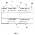
- the service center 130creates a digital certificate 901 that identifies the user's units that he has selected.
- the certificate 901includes each unit's serial number 903 , 905 , and the corresponding public key 904 , 905 .
- the name that the user has assigned to each unitis also cross referenced, as indicated by name 902 in the certificate 901 .
- the certificatecan contain any number of units that the user identifies, including PCs with USB dongles as described above.
- an expiration date 907is included in the certificate 901 .
- a digital signature 908is used so that units that receive the certificate can verify that the certificate actually originated from the service center 130 .
- the service center 130sends the certificate to each DVR 110 , 770 , listed in the certificate 901 over the network 140 (which may comprise the internet, a LAN, or other public or private network), phone line, or satellite connection.
- the certificate 901may be encrypted using the public key of each destination DVR 110 , 760 , 770 .
- a portable DVR 760can connect to the service center 130 via a network connection or phone line to receive its certificate. Alternatively, the portable DVR 760 can receive its certificate from a DVR 110 that it connects to.
- Each DVR 110 , 760 , 770verifies the certificate by decrypting the certificate and verifying the digital signature 908 in the certificate 901 . Once the DVR has verified that the digital signature 908 is from the service center 130 , the DVR finds the network locations of all peers that are listed in the certificate 901 , using a peer discovery protocol, such as Rendezvous from Apple Computer Inc. of Cupertino, Calif.
- a DVR 110Once a DVR 110 has discovered a peer 770 in the network, it sets up an encrypted connection with the peer 770 using the peer's public key from the certificate 901 .
- the encrypted connectionmay be “weakly” encrypted in that it is a function of two public keys, one from each peer. Each peer sends a message using the other's public key.
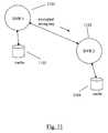
- a unitis designated as the content server, in this example, the content server 720 is provided by the service provider and is remotely located.
- the content server 720creates a more strongly encrypted connection with the DVR 110 by creating a random strong connection key and encrypts the strong key using the DVR's public key. The content server 720 then sends the encrypted strong key to the DVR 110 . The DVR 110 decrypts the strong key. In one approach, decryption may use hardware decryption elements. The two systems now share a secure key.
- the usercan request sending certain recorded content to the DVR 110 .
- the content server 720sends a previously encrypted recording to the DVR 110 , it loads a recording key that was used to encrypt the recording from its database and encrypts the recording key using the strong key.
- the content server 720sends the encrypted recording key to the DVR 110 .
- the DVR 110decrypts the recording key using the strong key that it shares with the content server 720 and stores the recording key.
- the content server 720sends the recorded content that it has stored locally to the DVR 110 .
- the recorded contenthas already been encrypted when it was originally stored locally by the content server 720 .
- the content server 720sends the recorded content without decrypting the content.
- the DVR 110writes the recorded content directly to its storage device without decoding it.
- the DVRplays the recorded content, it decodes the content on the fly.
- the approach described hereinpreserves the integrity of the recorded content because the content is in an encrypted state during transmission and is stored encrypted on the DVR, thereby preventing any unauthorized copying of the content.
- the content server 720sends an unencrypted recording to the DVR 110 , it creates a random recording key that will be used to encrypt the recording and encrypts the recording key using the strong key.
- the content server 720sends the encrypted recording key to the DVR 110 .
- the DVR 110decrypts the recording key using the strong key that it shares with the content server 720 and stores the recording key.
- the content server 720sends the recorded content that it has stored locally to the DVR 110 .
- the recorded contentwas not encrypted when it was originally stored locally by the content server 720 .
- the content server 720sends the recorded content, encrypting the content as it sends the content.
- the DVR 110writes the recorded content directly to its storage device without decoding it.
- the DVRplays the recorded content, it decodes the content on the fly.
- the approachstill preserves the integrity of the recorded content because the content is in an encrypted state during transmission and is stored encrypted on the DVR, thereby preventing any unauthorized copying of the content.
- FIG. 10shows a media server 1002 in a locally networked DVR setup in a house 1001 .
- DVR 1003is located in Bedroom 1
- DVR 1004is located in Bedroom 2
- DVR 1005is located in the Entertainment room.
- the media server 1002resides in the Living room.
- the usersends information instructing the service center 1006 that DVRs 1003 , 1004 , 1005 , and media server 1002 are authorized to share content and associates each unit by the room in which it resides.
- the service center 1006creates a certificate 901 that contains the media server's 1002 and each DVR's 1003 , 1004 , 1005 , serial number and public key along with an expiration date and the service center's digital signature.
- the media server 1002can be a PC, DVR, or other type of content server.
- the userdesignates the media server 1002 as the main source of multimedia content in the local network.
- the service center 1006sends the certificate to the media server 1002 and the DVRs 1003 , 1004 , 1005 , via the Internet 1007 .
- the media server 1002 and the DVRs 1003 , 1004 , 1005use the information in the certificate to discover their peers.
- the DVRs 1103 , 1004 , 1005discover that the media server 1002 is the only system that is serving content.
- Once the media server 1002 has established a weakly encrypted connection with each DVR 1003 , 1004 , 1005it creates a random strong connection key for each DVR 1003 , 1004 , 1005 .
- the media server 1002encrypts each strong key using the particular DVR's public key and sends the encrypted strong key to each DVR 1003 , 1004 , 1005 .
- the DVRuses its local crypto chip to decrypt the strong key.
- the media server 1002now shares a secure key with each DVR 1003 , 1004 , 1005 .
- each DVRhas access to the media server's contents.
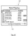
- the usergoes to the Now Playing screen 1601 (which is the similar in format and content to the Now Showing screen in FIG. 6 ) and sees all media servers that the user can access.
- a media server label 1602indicates that the user can access the DVR named “Bedroom.”
- the userselects the desired server using label 1602 and a content screen 1701 ( FIG. 17 ) is displayed that lists what content the media server has available.
- the usercan request that certain recorded content (music, photos, video, etc.) be sent to a particular DVR 1003 via the content screen 1701 .
- the usercan do this remotely as described above, or through the DVR 1003 itself.
- the userselects the options for transferring the selected content using a transfer options screen 1801 ( FIG. 18 ).
- the usercan select where to start the transfer from using a Start From option 1802 .
- the transfercan start from the beginning of the program, from where the user last paused, or at a certain time into the program.
- the usercan view and transfer music content and photo content in the same manner, as indicated by screen capture 2001 of FIG. 20 and screen capture 2101 of FIG. 21 .
- the media server 1002can send a previously encrypted recording to the DVR 1003 .
- the media server 1002loads a recording key that was used to encrypt the recording from its database and encrypts the recording key using the strong key.
- the media server 1002can optionally encrypt the recording key for storage in its database using a local encryption key. It is normally not desirable to store any of the encryption keys in cleartext, so simple encryption with a local key is best. It sends the encrypted recording key to the DVR 1003 .
- the DVR 1003decrypts the recording key using the strong key that it shares with the media server 1002 and stores the recording key.
- the DVR 1003can optionally encrypt the recording key using a local key before storage.
- the media server 1002sends the recorded content that it has stored locally to the DVR 1003 .
- the recorded contenthas already been encrypted when it was originally stored locally by the media server 1002 .
- the media server 1002sends the recorded content without decrypting the content.
- the DVR 1003writes the recorded content directly to its storage device without decoding it.
- the DVR 1003plays the recorded content, it decodes the content on the fly using the recording key.
- the usercan select the program information screen 1901 to see if the program is still transferring.
- the usercan play the program by selecting Play option 1902 while the transfer is in progress (as described above) or stop the transfer using Stop transfer option 1903 .
- the media server 1002sends an unencrypted recording to the DVR 1003 , it creates a random recording key that will be used to encrypt the recording and encrypts the recording key using the strong key.
- the media server 1002sends the encrypted recording key to the DVR 1003 .
- the DVR 1003decrypts the recording key using the strong key that it shares with the media server 1002 and stores the recording key.
- the DVR 1003can optionally encrypt the recording key using a local key before storage.
- the media server 1002sends the recorded content that it has stored locally to the DVR 1003 .
- the recorded contentwas not encrypted when it was originally stored locally by the media server 1002 .
- the media server 1002sends the recorded content, encrypting the content as it sends the content.
- the DVR 1003writes the recorded content directly to its storage device without decoding it.
- the DVR 1003plays the recorded content, it decodes the content on the fly using the recording key.
- the DVR 1003does not need to store the content on its storage device. It simply plays or displays the content immediately. If the content is encrypted, the DVR 1003 decrypts the content on the fly.
- DVR 1101may be required to create and store a plurality of strong keys for future use at the time that it is designated as the media server. Further, the receiving DVR requires many CPU cycles to decrypt the strong key upon receipt. This significantly slows down the DVR's overall performance.
- the techniques hereinsave the DVR 1101 the added burden of creating a new strong key whenever a DVR 1102 reboots or is restarted. It also saves DVR 1102 the burden of decrypting the strong key after reboot or restart.
- the DVR 1101originally creates a strong connection key, stores it in its local cache 1103 , and encrypts the key using the public key of the other DVR 1102 .
- the DVR 1101sends the encrypted strong key to the DVR 1102 .
- the DVR 1102decrypts the strong key and stores the key in its local cache 1104 along with the encrypted strong key and the machine serial number of DVR 1101 .
- the DVR 1102If the DVR 1102 reboots or is restarted, it does not know what its status is in the network. It may have been down for a few seconds or it may have been transplanted from another network.
- the DVR 1102requests the strong key from the DVR 1101 designated as the media server.
- the DVR 1101sends the strong key that it has stored in its local cache 1103 , or if the DVR 1102 has not had a strong connection established with the DVR 1101 , creates a new strong key.
- the strong keyis encrypted using the public key of the DVR 1102 and is sent to the DVR 1102 .
- the DVR 1102When the DVR 1102 receives the encrypted strong key, it checks the local cache 1104 for an entry from the DVR 1101 and, if it finds one, it does a bitwise comparison with the encrypted key in the local cache 1104 . If the two keys are the same, then the DVR 1102 uses the previously decrypted key stored in the local cache 1104 . Otherwise the DVR 1102 decrypts the newly sent key and stores the encrypted key, decrypted key, and DVR 1101 machine serial number in a new entry in the local cache 1104 . This way the long decryption step is avoided except when absolutely necessary.
- FIG. 12shows a modification of the digital certificate shown in FIG. 9 .
- the service center 130creates the certificate 901 which is distributed to DVRs 110 , 770 .
- the DVR 110 , 770will recognize a service entry using a specially-prefixed serial number in the service's serial number field 903 , for example: FFFxxxxxxxxxxxx, where the “xxxxxxxxxxxx” is used to provide additional information, such as version numbers, service provider, etc.
- the display name 902is set to something indicative of the service, such as “Special Videos”.
- the key field 1204 , 1206is filled in with a fully qualified domain name of the access point for the server.
- the certificate 901can contain a mix of service server information and peer unit information.
- the expiration date 907 and digital signature 908remain the same.
- the service center 130can place information in the fields in all, or a group, of certificates to name the same or different servers, etc.
- a DVR 110recognizes the service serial number in the certificate and sends a ping to the server using the domain name in the key field, for example, the key field 1204 , to see if it is reachable.
- the serverlooks up the DVR's public key and uses that to generate any other needed keys.
- the DVRdoes not need to possess a key for the server; the server generates the strong key for the session and encrypts the strong key with the DVR's public key. It then passes the encrypted strong key to the DVR.
- the DVR 110can then query the server for content.
- the serversynthesizes the appropriate metadata to describe what it has available and sends it to the DVR 110 . Since the metadata is synthesized, it can be uniquely created on a per-DVR basis. For example, a DVR owner may sign up for different kinds of services, such as history, drama, comedy, etc.
- the servercan instruct the DVR 110 to send its preference vector to the server, which the server uses to synthesize the appropriate metadata.
- the DVR's preference vectorcontains the user's viewing habits, e.g., what the user has indicated that he does and does not like, what he has consistently recorded using options such as a season pass subscription.
- the serverdoes not store the preference vector information; it simply discards the information after use. This preserves the user's privacy and makes sure the preferences are always kept on the DVR 110 .
- FIG. 16shows a Now Playing screen 1601 where available content from the DVR itself and other accessible servers and DVRs are displayed 1602 .
- An entry for content from a servicehas its associated name from the certificate listed.
- content from another DVRis listed using the name 1602 that the user has associated with it, if any exists. This way, the user knows the source of the content.
- FIG. 17shows the content screen 1701 displaying the name of the content source 1702 .
- FIGS. 20 and 21show a music content screen 2001 and photo content screen 2101 .
- DVRsthat are interested in downloading content from a server 1301 , ping the server 1301 .
- the server 1301runs the ping service, responding to requests from DVRs as they come in. This allows the server 1301 to maintain a record 1302 of all DVRs that are “signed up” to download video.
- the record 1302can later be audited to ensure, for example, that there are no clones of DVRs accessing the downloadable video from another IP address.
- the record 1302can also be used for billing purposes to track the length of time a user has his DVR 1303 signed up to download video.
- the DVR 1303contacts the server 1301 and requests the appropriate media object.
- the server 1301can record 1302 that the program is being downloaded, which may also include an entry into a billing system, etc.
- the recordscan be queried on the service center's Web site by a user 1304 so he can easily check his bill.
- a domain-name redirector 1402can be used that redirects a connection from a DVR 1401 to one of a group of third party servers 1403 , 1404 , 1405 . Redirection may occur based on load, the domain-name prefix used, etc. This allows the service center to redirect a request to another company's server. Redirection may involve a fee or revenue share in various embodiments.
- a domain name redirector 1402can reside on each third party server 1403 , 1404 , 1405 , so a request from a DVR 1401 can be redirected by the third party server itself.
- the DVR 1401requests a connection with third party server 1403 .
- Third party server 1403“delegates” its responsibilities to third party server 1404 by redirecting the request from the DVR 1401 to third party server 1404 .
- DVR 1401then contacts third party server 1404 for its content requests. This allows a third party server to judge by itself if is overloaded or cannot handle a request for any reason.
- content to be provided to a DVR 1503 , 1504 , 1505can initially be produced by a content server 1501 , such as a third party content server.
- the content server 1501does not have access to any information about the DVR's encryption techniques or architecture.
- a DVR 1502is used to encode and encrypt the content.
- the DVR 1502has a fast network engine and functions as an “encryption pipeline”. Data is sent from the content server 1501 to the DVR 1502 .
- the DVR 1502encodes (if needed) and encrypts the data while writing the data to its local storage device.
- the DVR 1502then reads the data from the local storage device without decrypting, and sends the data over the network to a target DVR selected from among DVR 1503 , 1504 , 1505 .
- Another approachprovides the third party content server with secure transmission of its content.
- Datais sent from the content server 1501 to the DVR 1502 using the content server's encryption technique.
- the DVR 1502decrypts the data using the content server's decryption technique.
- the DVR 1502then encodes (if needed) and encrypts (using the DVR's encryption technique) the data while writing the data to its local storage device.
- the DVR 1502then reads the data from the local storage device without decrypting, and sends the data over the network to a target DVR selected from among DVR 1503 , 1504 , 1505 .
- the media server in any of the foregoing embodimentscan be a PC, DVR, or any other mechanism that can serve content.
- the approaches described hereinallow the DVRs, as clients of the media server, to access multimedia content such as music, video, and photo content stored on media servers.
- multimedia contentsuch as music, video, and photo content stored on media servers.
- the DVRs and media serversmay have access to the Internet, the content need not originate nor be physically housed on any given media server.
- contentcan be made available to DVR users by arranging for a server to process a special file containing:
- Actual contentin the form of JPEG, MP3, or MPEG files, for example.
- DVR configuration settingsfor example, recording schedules, database modifications, content preferences, etc.
- Such filescan be provided to the DVR users via email or Internet download. Two example scenarios are described below that demonstrate how content can be sent via email to a DVR.
- a typical household DVR setup 2201is shown. Assume only the media server 2202 has access to the Internet 2205 .
- An email author 2204creates a content file with authoring software.
- the filefor example, contains the actual binary data for several images in JPEG format (it can contain any type of content).
- the content fileis emailed as an attachment to a user who accesses email from the same computer running the media server 2202 .
- Message communication mechanisms other than emailmay be used in alternative embodiments.
- the userreads the email and, if he is interested in the content, the user selects the attached content file, invoking the media server 2202 to process the content file.
- the media server 2202adds information about the images to an internal database from which container (metadata) information and JPEG data can be later generated.
- the usergoes to his DVR 2203 and accesses the “Music & Photos” feature via his television set, causing the DVR 2203 to request container information from the media server 2202 .
- the DVR 2203makes a request to the media server 2202 , which consults its internal database to render the appropriate JPEG data and pass the data to the DVR 2203 .
- the DVR 2203displays the image to the user and does not store the image on its local storage device.
- the usercan use trickplay functions on the multiple photo files such as fast forward, pause, reverse, play (slideshow), etc.
- a household DVR setup 2301is shown where both the DVR 2303 and media server 2302 have access to the Internet 2305 .
- An author 2304creates a content file with authoring software.
- the filelinks to one or more content files, such as MP3 music files, housed on the content server 2306 and served via HTTP.
- the content fileis emailed as an attachment to a user who (ideally) accesses email from the same computer running the media server 2302 .
- the userreads the email and, if he is interested in the content, the user selects the attached content file, invoking the media server 2302 to process the content file.
- the media server 2302adds information about the content files to an internal database from which container information can be later generated.
- the customergoes to his DVR 2303 and accesses the “Music & Photos” feature, causing the DVR 2203 to request container information from the media server 2302 .
- the customercan now access one with music served by the content server 2306 .
- the DVR 2303accesses the content server 2306 directly over the Internet 2305 to retrieve the appropriate data.
- the usercan use trickplay functions on the music files such as fast forward, pause, reverse, play, etc.
- the progress of through the musicis displayed to the user through a connected television set using a replay bar as shown in FIG. 8 .
- the DVR 2303does not store the music on its storage device for copyright protection.
- the two preceding examplescan be used for any type of content that a DVR can use or display. If configuration information is received, the DVR 2303 will store the configuration information on its local storage device and use the configuration information to configure itself. If video is received, the DVR 2303 can store the video content on its local storage device for later playback by the user. The user can use trickplay functions on the video content such as fast forward, pause, reverse, play, slow play, frame step, etc.
- DVR userscould use the approach to share content with each other via email. For example, one user could send to another user a content file with links to personal photos housed on the first customer's PC.
- a record labelcould promote a new album by sending a content file with links to MP3 files containing sample songs.
- Third party partnerscan use the approach herein to deliver product to DVR users via email.
- a film processing labcould email a content file containing digitized photos purchased online by a DVR user.
Landscapes
- Engineering & Computer Science (AREA)
- Computer Security & Cryptography (AREA)
- Signal Processing (AREA)
- Computer Networks & Wireless Communication (AREA)
- Computer Hardware Design (AREA)
- General Engineering & Computer Science (AREA)
- Multimedia (AREA)
- Computing Systems (AREA)
- Databases & Information Systems (AREA)
- Theoretical Computer Science (AREA)
- Computer Graphics (AREA)
- Software Systems (AREA)
- Physics & Mathematics (AREA)
- General Physics & Mathematics (AREA)
- Television Signal Processing For Recording (AREA)
- Two-Way Televisions, Distribution Of Moving Picture Or The Like (AREA)
- Storage Device Security (AREA)
Abstract
Description
- Step400: The
Web server 200 ormicro server 250 presents an authorization request form in the first Web page to the user who accesses a special Web site that is managed by theWeb server 200 or themicro server 250; - Step410: The
Web server 200 receives an authorization password entered by the user; themicro server 250 receives an authorization key from the user; - Step420: The
Web server 200 validates the authorization password using theuser database 220; themicro server 250 validates the authorization key with the key that it has stored. - Step430: Once the
Web server 200 has validated the authorization password in theuser database 220, it writes a cookie in the non-volatile memory of theremote computer 155 or personaldigital assistant 160; once themicro server 250 has validated the authorization key, it writes a cookie in the non-volatile memory of theremote computer 155 or personaldigital assistant 160; - Step440: The
Web server 200 ormicro server 250 presents a program guide to the user after the user is identified and authenticated; - Step450: The
Web server 200 receives the user selections and creates an event list350 specific to the user. The event list350 is stored in theevent database 230. Themicro server 200 receives the user selections and places them on theevent queue 270.
- Step400: The
Claims (60)
Priority Applications (7)
| Application Number | Priority Date | Filing Date | Title |
|---|---|---|---|
| US10/741,596US8812850B2 (en) | 2000-03-02 | 2003-12-18 | Secure multimedia transfer system |
| HK09106874.9AHK1127728B (en) | 2003-12-18 | 2004-12-16 | Secure multimedia transfer system |
| CN2004800414603ACN101421974B (en) | 2003-12-18 | 2004-12-16 | Secure multimedia transfer system |
| JP2006545414AJP4884978B2 (en) | 2003-12-18 | 2004-12-16 | Secure multimedia transfer system |
| PCT/US2004/042211WO2005060659A2 (en) | 2003-12-18 | 2004-12-16 | Secure multimedia transfer system |
| EP04814400.0AEP1702455B1 (en) | 2003-12-18 | 2004-12-16 | Secure multimedia transfer system |
| US14/460,993US9854289B2 (en) | 2000-03-02 | 2014-08-15 | Secure multimedia transfer system |
Applications Claiming Priority (5)
| Application Number | Priority Date | Filing Date | Title |
|---|---|---|---|
| US18655100P | 2000-03-02 | 2000-03-02 | |
| PCT/US2001/006313WO2001065862A2 (en) | 2000-03-02 | 2001-02-27 | System and method for internet access to personal television service |
| US10/220,558US7908635B2 (en) | 2000-03-02 | 2001-02-27 | System and method for internet access to a personal television service |
| US43476702P | 2002-12-18 | 2002-12-18 | |
| US10/741,596US8812850B2 (en) | 2000-03-02 | 2003-12-18 | Secure multimedia transfer system |
Related Parent Applications (3)
| Application Number | Title | Priority Date | Filing Date |
|---|---|---|---|
| PCT/US2001/006313Continuation-In-PartWO2001065862A2 (en) | 2000-03-02 | 2001-02-27 | System and method for internet access to personal television service |
| US10220558Continuation-In-Part | 2001-02-27 | ||
| US10/220,558Continuation-In-PartUS7908635B2 (en) | 2000-03-02 | 2001-02-27 | System and method for internet access to a personal television service |
Related Child Applications (1)
| Application Number | Title | Priority Date | Filing Date |
|---|---|---|---|
| US14/460,993ContinuationUS9854289B2 (en) | 2000-03-02 | 2014-08-15 | Secure multimedia transfer system |
Publications (2)
| Publication Number | Publication Date |
|---|---|
| US20050108519A1 US20050108519A1 (en) | 2005-05-19 |
| US8812850B2true US8812850B2 (en) | 2014-08-19 |
Family
ID=34710530
Family Applications (2)
| Application Number | Title | Priority Date | Filing Date |
|---|---|---|---|
| US10/741,596Expired - LifetimeUS8812850B2 (en) | 2000-03-02 | 2003-12-18 | Secure multimedia transfer system |
| US14/460,993Expired - Fee RelatedUS9854289B2 (en) | 2000-03-02 | 2014-08-15 | Secure multimedia transfer system |
Family Applications After (1)
| Application Number | Title | Priority Date | Filing Date |
|---|---|---|---|
| US14/460,993Expired - Fee RelatedUS9854289B2 (en) | 2000-03-02 | 2014-08-15 | Secure multimedia transfer system |
Country Status (5)
| Country | Link |
|---|---|
| US (2) | US8812850B2 (en) |
| EP (1) | EP1702455B1 (en) |
| JP (1) | JP4884978B2 (en) |
| CN (1) | CN101421974B (en) |
| WO (1) | WO2005060659A2 (en) |
Cited By (4)
| Publication number | Priority date | Publication date | Assignee | Title |
|---|---|---|---|---|
| US20080212779A1 (en)* | 2005-01-21 | 2008-09-04 | Koninklijke Philips Electronics, N.V. | Ordering Content by Mobile Phone to be Played on Consumer Devices |
| US20150325271A1 (en)* | 2014-05-09 | 2015-11-12 | Lg Electronics Inc. | Terminal and operating method thereof |
| US9600640B2 (en) | 2004-05-19 | 2017-03-21 | Digital Media Technologies, Inc. | Multimedia network system with content importation, content exportation, and integrated content management |
| US20220329572A1 (en)* | 2017-07-18 | 2022-10-13 | Google Llc | Methods, systems, and media for protecting and verifying video files |
Families Citing this family (74)
| Publication number | Priority date | Publication date | Assignee | Title |
|---|---|---|---|---|
| CN1867068A (en) | 1998-07-14 | 2006-11-22 | 联合视频制品公司 | Client-server based interactive television program guide system with remote server recording |
| US7558472B2 (en) | 2000-08-22 | 2009-07-07 | Tivo Inc. | Multimedia signal processing system |
| US6233389B1 (en) | 1998-07-30 | 2001-05-15 | Tivo, Inc. | Multimedia time warping system |
| CN100379273C (en) | 1999-09-20 | 2008-04-02 | 提维股份有限公司 | Closed caption tagging system |
| US7908635B2 (en) | 2000-03-02 | 2011-03-15 | Tivo Inc. | System and method for internet access to a personal television service |
| US8261315B2 (en)* | 2000-03-02 | 2012-09-04 | Tivo Inc. | Multicasting multimedia content distribution system |
| AU2001241972A1 (en) | 2000-03-02 | 2001-09-12 | Tivo, Inc. | Conditional access system and method for prevention of replay attacks |
| US8171520B2 (en)* | 2000-03-02 | 2012-05-01 | Tivo Inc. | Method of sharing personal media using a digital recorder |
| US8812850B2 (en) | 2000-03-02 | 2014-08-19 | Tivo Inc. | Secure multimedia transfer system |
| US7951002B1 (en) | 2000-06-16 | 2011-05-31 | Igt | Using a gaming machine as a server |
| US7457414B1 (en)* | 2000-07-21 | 2008-11-25 | The Directv Group, Inc. | Super encrypted storage and retrieval of media programs with smartcard generated keys |
| US7203311B1 (en) | 2000-07-21 | 2007-04-10 | The Directv Group, Inc. | Super encrypted storage and retrieval of media programs in a hard-paired receiver and storage device |
| US7203314B1 (en) | 2000-07-21 | 2007-04-10 | The Directv Group, Inc. | Super encrypted storage and retrieval of media programs with modified conditional access functionality |
| US8140859B1 (en) | 2000-07-21 | 2012-03-20 | The Directv Group, Inc. | Secure storage and replay of media programs using a hard-paired receiver and storage device |
| US7972214B2 (en) | 2000-12-07 | 2011-07-05 | Igt | Methods and devices for downloading games of chance |
| US7409562B2 (en) | 2001-09-21 | 2008-08-05 | The Directv Group, Inc. | Method and apparatus for encrypting media programs for later purchase and viewing |
| US7797552B2 (en) | 2001-09-21 | 2010-09-14 | The Directv Group, Inc. | Method and apparatus for controlling paired operation of a conditional access module and an integrated receiver and decoder |
| US8597116B2 (en) | 2002-03-12 | 2013-12-03 | Igt | Virtual player tracking and related services |
| US6997803B2 (en) | 2002-03-12 | 2006-02-14 | Igt | Virtual gaming peripherals for a gaming machine |
| US7787749B2 (en)* | 2003-03-07 | 2010-08-31 | Siemens Enterprise Communications, Inc. | System and method for voice portal control of an integrated communications center |
| CN1610396A (en)* | 2003-10-20 | 2005-04-27 | 松下电器产业株式会社 | Video recorder and video server system |
| US20050188224A1 (en)* | 2004-01-05 | 2005-08-25 | Betts-Lacroix Jonathan | Connector including electronic device |
| US7590243B2 (en)* | 2004-05-04 | 2009-09-15 | The Directv Group, Inc. | Digital media conditional access system for handling digital media content |
| JP4250564B2 (en)* | 2004-06-08 | 2009-04-08 | 株式会社東芝 | Method for processing simultaneous recording of copy-restricted content and video equipment thereof |
| CN102665112B (en) | 2004-11-19 | 2015-08-19 | Tivo股份有限公司 | For the safe transmission of content of multimedia and the method and apparatus of playback |
| SG158079A1 (en)* | 2004-11-19 | 2010-01-29 | Tivo Inc | Method and apparatus for secure transfer and playback of multimedia content |
| US9325944B2 (en) | 2005-08-11 | 2016-04-26 | The Directv Group, Inc. | Secure delivery of program content via a removable storage medium |
| US20070053379A1 (en)* | 2005-09-06 | 2007-03-08 | Mark Hershey | Streaming media encoder with confidence monitor |
| US7818442B2 (en)* | 2005-09-06 | 2010-10-19 | Viewcast.Com, Inc. | Streaming media encoder with front panel control interface |
| US7887420B2 (en)* | 2005-09-12 | 2011-02-15 | Igt | Method and system for instant-on game download |
| US8287379B2 (en) | 2005-09-12 | 2012-10-16 | Igt | Distributed game services |
| US7275196B2 (en)* | 2005-11-23 | 2007-09-25 | M2000 S.A. | Runtime reconfiguration of reconfigurable circuits |
| CN101009551B (en)* | 2006-01-24 | 2010-12-08 | 华为技术有限公司 | Key management system and method for media stream based on IP multimedia subsystem |
| US20070180062A1 (en)* | 2006-01-31 | 2007-08-02 | Viewcast.Com, Inc. D/B/A Viewcast Corporation | Portable media encoder with remote setup management interface |
| US7747798B2 (en)* | 2006-01-31 | 2010-06-29 | Viewcast.Com, Inc. | Portable media encoder |
| US20070189411A1 (en)* | 2006-02-14 | 2007-08-16 | Viewcast.Com, Inc. | Audio encoding and transmission method |
| US8095466B2 (en) | 2006-05-15 | 2012-01-10 | The Directv Group, Inc. | Methods and apparatus to conditionally authorize content delivery at content servers in pay delivery systems |
| US8996421B2 (en) | 2006-05-15 | 2015-03-31 | The Directv Group, Inc. | Methods and apparatus to conditionally authorize content delivery at broadcast headends in pay delivery systems |
| US7992175B2 (en) | 2006-05-15 | 2011-08-02 | The Directv Group, Inc. | Methods and apparatus to provide content on demand in content broadcast systems |
| US8001565B2 (en) | 2006-05-15 | 2011-08-16 | The Directv Group, Inc. | Methods and apparatus to conditionally authorize content delivery at receivers in pay delivery systems |
| US8775319B2 (en) | 2006-05-15 | 2014-07-08 | The Directv Group, Inc. | Secure content transfer systems and methods to operate the same |
| US9178693B2 (en) | 2006-08-04 | 2015-11-03 | The Directv Group, Inc. | Distributed media-protection systems and methods to operate the same |
| US9225761B2 (en) | 2006-08-04 | 2015-12-29 | The Directv Group, Inc. | Distributed media-aggregation systems and methods to operate the same |
| US8520850B2 (en) | 2006-10-20 | 2013-08-27 | Time Warner Cable Enterprises Llc | Downloadable security and protection methods and apparatus |
| US8225096B2 (en)* | 2006-10-27 | 2012-07-17 | International Business Machines Corporation | System, apparatus, method, and program product for authenticating communication partner using electronic certificate containing personal information |
| US20080271095A1 (en)* | 2007-04-24 | 2008-10-30 | Yahoo! Inc. | Method and system for previewing media over a network |
| JP5253850B2 (en)* | 2008-03-14 | 2013-07-31 | ソニー株式会社 | Portable information terminal, viewing device, information providing device, device control device, cooperative processing system, and program |
| US8559637B2 (en)* | 2008-09-10 | 2013-10-15 | Verizon Patent And Licensing Inc. | Securing information exchanged via a network |
| US10235832B2 (en) | 2008-10-17 | 2019-03-19 | Igt | Post certification metering for diverse game machines |
| CN101763469B (en)* | 2008-12-24 | 2014-06-25 | 上海盛轩网络科技有限公司 | Digital copyright management system and implementation method thereof |
| JP2011008701A (en)* | 2009-06-29 | 2011-01-13 | Sony Corp | Information processing server, information processing apparatus, and information processing method |
| US8761392B2 (en)* | 2009-09-29 | 2014-06-24 | Motorola Mobility Llc | Digital rights management protection for content identified using a social TV service |
| US8335819B2 (en)* | 2009-12-31 | 2012-12-18 | Nokia Corporation | Method and apparatus for providing client-side caching |
| US8843736B2 (en) | 2010-05-04 | 2014-09-23 | Sony Corporation | Authentication and authorization for internet video client |
| CA2740111C (en) | 2010-05-10 | 2019-01-15 | Encore Interactive Inc. | Realtime broadcast stream and control data conversion system and method |
| US8458741B2 (en)* | 2010-05-27 | 2013-06-04 | Sony Corporation | Provision of TV ID to non-TV device to enable access to TV services |
| US8407755B2 (en) | 2010-07-27 | 2013-03-26 | Sony Corporation | Control of IPTV using second device |
| US9281999B2 (en) | 2010-09-30 | 2016-03-08 | American Megatrends, Inc. | Apparatus for remotely configuring network interfaces in a remote management system |
| US8843607B2 (en)* | 2010-09-30 | 2014-09-23 | American Megatrends, Inc. | System and method for managing computer network interfaces |
| US8742717B2 (en) | 2011-04-27 | 2014-06-03 | American Megatrends, Inc. | Method and apparatus to harness keyboard strokes and mouse movement to charge an electrical storage device |
| US9414109B2 (en)* | 2011-08-31 | 2016-08-09 | Tivo Inc. | Multimedia program recording schedule manager |
| US9792451B2 (en)* | 2011-12-09 | 2017-10-17 | Echarge2 Corporation | System and methods for using cipher objects to protect data |
| US9241355B2 (en) | 2013-09-30 | 2016-01-19 | Sonos, Inc. | Media system access via cellular network |
| JP6269209B2 (en)* | 2014-03-18 | 2018-01-31 | 富士通株式会社 | Information processing apparatus, method, and program |
| FR3019418A1 (en)* | 2014-03-31 | 2015-10-02 | Orange | DEVICE AND METHOD FOR DEPORTING THE RESTITUTION OF MULTIMEDIA CONTENT |
| US9621940B2 (en)* | 2014-05-29 | 2017-04-11 | Time Warner Cable Enterprises Llc | Apparatus and methods for recording, accessing, and delivering packetized content |
| US10034027B2 (en) | 2016-03-10 | 2018-07-24 | Sony Corporation | Automatic MSO-based transfer of DVR content to new location of customer |
| PL3220629T3 (en)* | 2016-03-17 | 2019-04-30 | HD PLUS GmbH | Method and system for generating a media channel access list |
| CN106131008B (en)* | 2016-07-07 | 2020-05-05 | 北京仁信证科技有限公司 | Video and audio monitoring equipment, security authentication method thereof and video and audio display equipment |
| US11063748B2 (en) | 2017-06-04 | 2021-07-13 | Apple Inc. | Synchronizing content |
| US11182349B2 (en) | 2017-06-04 | 2021-11-23 | Apple Inc. | Synchronizing content |
| US10719722B2 (en)* | 2017-11-12 | 2020-07-21 | Bendix Commercial Vehicle Systems Llc | Driving oriented digital video recorder system |
| US11681781B2 (en)* | 2018-02-21 | 2023-06-20 | Comcast Cable Communications, Llc | Systems and methods for content security |
| US12225111B2 (en)* | 2022-03-08 | 2025-02-11 | SanDisk Technologies, Inc. | Authorization requests from a data storage device to multiple manager devices |
Citations (109)
| Publication number | Priority date | Publication date | Assignee | Title |
|---|---|---|---|---|
| US5371794A (en)* | 1993-11-02 | 1994-12-06 | Sun Microsystems, Inc. | Method and apparatus for privacy and authentication in wireless networks |
| WO1997013368A1 (en) | 1995-10-02 | 1997-04-10 | Starsight Telecast, Incorporated | Systems and methods for providing television schedule information |
| US5721827A (en) | 1996-10-02 | 1998-02-24 | James Logan | System for electrically distributing personalized information |
| EP0854645A2 (en) | 1997-01-03 | 1998-07-22 | Texas Instruments Incorporated | Electronic television program guide system and method |
| US5883901A (en) | 1995-09-22 | 1999-03-16 | Hewlett-Packard Company | Communications system including synchronization information for timing upstream transmission of data and ability to vary slot duration |
| DE19740079A1 (en) | 1997-09-12 | 1999-03-18 | Ciburski Guido | Video recorder remote control method |
| EP0909094A1 (en) | 1997-10-07 | 1999-04-14 | CANAL+ Société Anonyme | Multithread data processor |
| US5896566A (en) | 1995-07-28 | 1999-04-20 | Motorola, Inc. | Method for indicating availability of updated software to portable wireless communication units |
| JPH11110401A (en) | 1997-09-30 | 1999-04-23 | Nippon Telegr & Teleph Corp <Ntt> | Broadcast-type distribution filtering method and system, and storage medium storing broadcast-type distribution filtering program |
| US5963909A (en) | 1995-12-06 | 1999-10-05 | Solana Technology Development Corporation | Multi-media copy management system |
| WO1999052278A1 (en) | 1998-04-03 | 1999-10-14 | Matsushita Electric Industrial Co., Ltd. | Portable viewing system |
| US5990884A (en)* | 1997-05-02 | 1999-11-23 | Sony Corporation | Control of multimedia information with interface specification stored on multimedia component |
| WO1999065237A1 (en) | 1998-06-12 | 1999-12-16 | Metabyte, Inc. | Television program recording with user preference determination |
| WO2000001149A1 (en) | 1998-06-29 | 2000-01-06 | Nds Limited | Advanced television system |
| WO2000004549A2 (en) | 1998-07-14 | 2000-01-27 | Koninklijke Philips Electronics N.V. | Copy protection by ticket encryption |
| EP0977200A1 (en) | 1998-02-19 | 2000-02-02 | Sony Corporation | Recorder / reproducer, recording / reproducing method, and data processor |
| WO2000007368A1 (en) | 1998-07-30 | 2000-02-10 | Tivo, Inc. | Multimedia time warping system |
| US6025868A (en) | 1995-02-24 | 2000-02-15 | Smart Vcr Limited Partnership | Stored program pay-per-play |
| US6025686A (en) | 1997-07-23 | 2000-02-15 | Harnischfeger Corporation | Method and system for controlling movement of a digging dipper |
| US6040851A (en) | 1998-01-20 | 2000-03-21 | Conexant Systems, Inc. | Small-format subsystem for broadband communication services |
| US6065050A (en) | 1996-06-05 | 2000-05-16 | Sun Microsystems, Inc. | System and method for indexing between trick play and normal play video streams in a video delivery system |
| US6092201A (en)* | 1997-10-24 | 2000-07-18 | Entrust Technologies | Method and apparatus for extending secure communication operations via a shared list |
| WO2000076217A1 (en) | 1999-06-03 | 2000-12-14 | Opentv, Inc. | Home digital assistant |
| WO2000075925A1 (en) | 1999-06-08 | 2000-12-14 | Intertrust Technologies Corp. | Method and systems for protecting data using digital signature and watermark |
| WO2001010127A1 (en) | 1999-08-03 | 2001-02-08 | Videoshare, Inc. | Method and system for sharing video over a network |
| EP1079628A2 (en) | 1999-08-23 | 2001-02-28 | Victor Company Of Japan, Limited | Copyrighted digital data management method and system |
| US6219839B1 (en) | 1998-05-12 | 2001-04-17 | Sharp Laboratories Of America, Inc. | On-screen electronic resources guide |
| WO2001033427A2 (en) | 1999-10-25 | 2001-05-10 | Oracle Corporation | Storing multidimensional data in a relational database |
| EP1102481A1 (en) | 1999-11-19 | 2001-05-23 | Pace Micro Technology Ltd | Improvements to data receiving apparatus |
| US6247176B1 (en) | 1996-06-14 | 2001-06-12 | Starsight Telecast, Inc. | Television schedule system and method of operation for multiple program occurrences |
| US6260142B1 (en)* | 1998-10-08 | 2001-07-10 | Entrust Technologies Limited | Access and storage of secure group communication cryptographic keys |
| US6269099B1 (en)* | 1998-07-01 | 2001-07-31 | 3Com Corporation | Protocol and method for peer network device discovery |
| US6275850B1 (en) | 1998-07-24 | 2001-08-14 | Siemens Information And Communication Networks, Inc. | Method and system for management of message attachments |
| WO2001065862A2 (en) | 2000-03-02 | 2001-09-07 | Tivo, Inc. | System and method for internet access to personal television service |
| US6289169B1 (en) | 1998-05-07 | 2001-09-11 | Kabushiki Kaisha Toshiba | Apparatus and method of displaying recording |
| WO2001067756A2 (en) | 2000-03-08 | 2001-09-13 | General Instrument Corporation | Personal versatile recorder and method of implementing and using same |
| US20010051996A1 (en) | 2000-02-18 | 2001-12-13 | Cooper Robin Ross | Network-based content distribution system |
| US6351538B1 (en)* | 1998-10-06 | 2002-02-26 | Lsi Logic Corporation | Conditional access and copy protection scheme for MPEG encoded video data |
| US20020044656A1 (en) | 1999-10-13 | 2002-04-18 | Brant L. Candelore | Interfacing a conditional access circuit to a digital device using input and output stream switching |
| US6385728B1 (en) | 1997-11-26 | 2002-05-07 | International Business Machines Corporation | System, method, and program for providing will-call certificates for guaranteeing authorization for a printer to retrieve a file directly from a file server upon request from a client in a network computer system environment |
| US6385596B1 (en) | 1998-02-06 | 2002-05-07 | Liquid Audio, Inc. | Secure online music distribution system |
| US20020054752A1 (en) | 1998-08-07 | 2002-05-09 | Anthony Wood | Video data recorder with personal channels |
| US20020059363A1 (en)* | 1996-09-12 | 2002-05-16 | Donald R. Katz | Digital information library and delivery system with logic for generating files targeting a playback device |
| US20020057893A1 (en) | 1998-08-11 | 2002-05-16 | Anthony Wood | Digital recording and playback |
| WO2002043353A2 (en) | 2000-11-16 | 2002-05-30 | Mydtv, Inc. | System and methods for determining the desirability of video programming events |
| US20020100052A1 (en) | 1999-01-06 | 2002-07-25 | Daniels John J. | Methods for enabling near video-on-demand and video-on-request services using digital video recorders |
| JP2002222138A (en) | 2000-11-24 | 2002-08-09 | Matsushita Electric Ind Co Ltd | Content transmission method, content reception method, and content distribution system |
| US20020144262A1 (en) | 2001-04-03 | 2002-10-03 | Plotnick Michael A. | Alternative advertising in prerecorded media |
| US6463444B1 (en) | 1997-08-14 | 2002-10-08 | Virage, Inc. | Video cataloger system with extensibility |
| US20020147686A1 (en) | 2001-04-06 | 2002-10-10 | General Instrument Corporation | Method and apparatus for a playback area network |
| US20020164156A1 (en) | 2001-05-02 | 2002-11-07 | Brett Bilbrey | Portable player for personal video recorders |
| US20030033606A1 (en) | 2001-08-07 | 2003-02-13 | Puente David S. | Streaming media publishing system and method |
| US6522342B1 (en) | 1999-01-27 | 2003-02-18 | Hughes Electronics Corporation | Graphical tuning bar for a multi-program data stream |
| JP2003108371A (en) | 2001-09-27 | 2003-04-11 | Rainbow Partner Inc | Organization of program for server built in equipment |
| US20030076955A1 (en) | 2001-10-18 | 2003-04-24 | Jukka Alve | System and method for controlled copying and moving of content between devices and domains based on conditional encryption of content key depending on usage state |
| US20030093790A1 (en) | 2000-03-28 | 2003-05-15 | Logan James D. | Audio and video program recording, editing and playback systems using metadata |
| JP2003141031A (en) | 2001-11-05 | 2003-05-16 | Ick Solutions Corp | Album generating program and method |
| US20030097338A1 (en)* | 2000-02-03 | 2003-05-22 | Piotrowski Tony E. | Method and system for purchasing content related material |
| US20030106072A1 (en) | 2001-12-05 | 2003-06-05 | Koninklijke Philips Electronics N.V. | Multimedia storage and control system |
| US20030110503A1 (en) | 2001-10-25 | 2003-06-12 | Perkes Ronald M. | System, method and computer program product for presenting media to a user in a media on demand framework |
| US20030118014A1 (en) | 2001-12-21 | 2003-06-26 | Iyer Ravishankar R. | Method and system for customized television viewing using a peer-to-peer network |
| US20030122922A1 (en) | 2001-11-26 | 2003-07-03 | Saffer Kevin D. | Video e-mail system and associated method |
| US20030145323A1 (en) | 1992-12-09 | 2003-07-31 | Hendricks John S. | Targeted advertisement using television viewer information |
| US20030149988A1 (en) | 1998-07-14 | 2003-08-07 | United Video Properties, Inc. | Client server based interactive television program guide system with remote server recording |
| US20030158958A1 (en) | 2002-02-20 | 2003-08-21 | Koninklijke Philips Electronics N.V. | Distributed storage network architecture using user devices |
| JP2003259333A (en) | 2002-03-04 | 2003-09-12 | Toshiba Corp | A digital signal transmitting device, a digital signal receiving device, and a digital signal transmitting / receiving method. |
| US20030188153A1 (en) | 2002-04-02 | 2003-10-02 | Demoff Jeff S. | System and method for mirroring data using a server |
| US20030204613A1 (en) | 2002-04-26 | 2003-10-30 | Hudson Michael D. | System and methods of streaming media files from a dispersed peer network to maintain quality of service |
| US20030204856A1 (en) | 2002-04-30 | 2003-10-30 | Buxton Mark J. | Distributed server video-on-demand system |
| US20030217328A1 (en) | 2002-05-17 | 2003-11-20 | Shai Agassi | Rich media information portals |
| US20030215211A1 (en) | 2002-05-20 | 2003-11-20 | Coffin Louis F. | PC-based personal video recorder |
| JP2003333574A (en) | 2002-05-16 | 2003-11-21 | Bb Cable Corp | Vod contents distribution system, vod contents distribution method, vod contents distribution and program broadcast system, vod contents distribution and program broadcast method, multicast distribution system for vod contents distribution and program contents, multicast distribution method for vod contents distribution and program contents, and program allowing computer to execute the method |
| US20030233663A1 (en) | 2002-06-14 | 2003-12-18 | Rao Ram R. | Transcoding media content from a personal video recorder for a portable device |
| WO2004001614A1 (en) | 2002-06-21 | 2003-12-31 | Thomson Licensing S.A. | Streaming media delivery on multicast networks for network and server bandwidth minimization and enhanced personalization |
| US20040003398A1 (en) | 2002-06-27 | 2004-01-01 | Donian Philip M. | Method and apparatus for the free licensing of digital media content |
| US20040008289A1 (en) | 2002-07-12 | 2004-01-15 | Samsung Electronics Co., Ltd. | Apparatus and method for correcting CRT focusing |
| US20040086263A1 (en) | 2002-10-31 | 2004-05-06 | Jitesh Arora | System for maintaining history of multimedia content and method thereof |
| US20040109675A1 (en) | 1998-03-03 | 2004-06-10 | Matsushita Electric Industrial Co., Ltd. | Terminal device for recording broadcast information and/or playing video and/audio data |
| US6751321B1 (en)* | 1997-04-24 | 2004-06-15 | Kabushiki Kaisha Toshiba | Digital data reproduction device |
| US20040117483A1 (en) | 2002-12-17 | 2004-06-17 | Singer Mitch Fredrick | License management in a media network environment |
| US6754885B1 (en) | 1999-05-17 | 2004-06-22 | Invensys Systems, Inc. | Methods and apparatus for controlling object appearance in a process control configuration system |
| JP2004193920A (en) | 2002-12-11 | 2004-07-08 | Toshiba Corp | Program distribution system and receiving device |
| US20040163130A1 (en) | 2002-03-27 | 2004-08-19 | Gray James H. | Method to enable cooperative processing and resource sharing between set-top boxes, personal computers, and local devices |
| US20040237100A1 (en) | 2002-05-24 | 2004-11-25 | Pinder Howard G. | Validating client-receivers |
| US20040243815A1 (en) | 2003-05-28 | 2004-12-02 | Yoshihiro Tsukamura | System and method of distributing and controlling rights of digital content |
| US20040261093A1 (en) | 2003-02-24 | 2004-12-23 | Rebaud Sylvain P. | Media service delivery system providing conditional access to media content from various client devices |
| US20040268386A1 (en) | 2002-06-08 | 2004-12-30 | Gotuit Video, Inc. | Virtual DVD library |
| US6851063B1 (en) | 2000-09-30 | 2005-02-01 | Keen Personal Technologies, Inc. | Digital video recorder employing a file system encrypted using a pseudo-random sequence generated from a unique ID |
| US20050028208A1 (en) | 1998-07-17 | 2005-02-03 | United Video Properties, Inc. | Interactive television program guide with remote access |
| US20050076359A1 (en) | 1999-12-21 | 2005-04-07 | Andrew Pierson | Modifying commercials for multi-speed playback |
| US20050108769A1 (en) | 2000-03-02 | 2005-05-19 | Tivo Inc. | Method of sharing personal media using a digital recorder |
| US6917610B1 (en) | 1999-12-30 | 2005-07-12 | At&T Corp. | Activity log for improved call efficiency |
| US20050166258A1 (en) | 2002-02-08 | 2005-07-28 | Alexander Vasilevsky | Centralized digital video recording system with bookmarking and playback from multiple locations |
| US6941387B1 (en) | 1997-02-17 | 2005-09-06 | Sony Corporation | Electronic equipment controlling apparatus and method, electronic equipment controlling system and electronic equipment |
| US20050216942A1 (en) | 2000-03-02 | 2005-09-29 | Tivo Inc. | Multicasting multimedia content distribution system |
| US6972786B1 (en) | 1994-12-30 | 2005-12-06 | Collaboration Properties, Inc. | Multimedia services using central office |
| US6981147B1 (en)* | 1999-01-29 | 2005-12-27 | International Business Machines Corporation | Certification of multiple keys with new base and supplementary certificate types |
| US7006881B1 (en) | 1991-12-23 | 2006-02-28 | Steven Hoffberg | Media recording device with remote graphic user interface |
| US7065778B1 (en) | 2001-05-25 | 2006-06-20 | Enreach Technologies, Inc. | Method and system for providing media from remote locations to a viewer |
| US7080400B1 (en) | 2001-08-06 | 2006-07-18 | Navar Murgesh S | System and method for distributed storage and presentation of multimedia in a cable network environment |
| US7113994B1 (en) | 2000-01-24 | 2006-09-26 | Microsoft Corporation | System and method of proxy authentication in a secured network |
| US7260715B1 (en)* | 1999-12-09 | 2007-08-21 | Koninklijke Philips Electronics N.V. | Method and apparatus for revocation list management |
| US20080104202A1 (en) | 2006-10-25 | 2008-05-01 | Microsoft Corporation | Multi-DVR Media Content Arbitration |
| US7870584B2 (en) | 2002-08-02 | 2011-01-11 | Russ Samuel H | Interactive program guide with selectable updating |
| US20110061071A1 (en) | 2000-03-02 | 2011-03-10 | Barton James M | System and method for internet access to a personal television service |
| US7929560B2 (en) | 2005-07-15 | 2011-04-19 | Panasonic Corporation | Packet transmitting apparatus |
| US8214422B1 (en) | 2001-08-19 | 2012-07-03 | The Directv Group, Inc. | Methods and apparatus for sending content between client devices |
| US8601507B2 (en) | 2002-03-12 | 2013-12-03 | Arris Enterprises, Inc. | System and method for focused navigation in a media center/extension device architecture |
| US8627385B2 (en) | 2002-10-04 | 2014-01-07 | David B. Davies | Systems and methods for operating a peripheral record playback device in a networked multimedia system |
Family Cites Families (64)
| Publication number | Priority date | Publication date | Assignee | Title |
|---|---|---|---|---|
| JPH0787082A (en) | 1993-09-14 | 1995-03-31 | N T T Data Tsushin Kk | Information reproduction system |
| US5638200A (en) | 1995-02-03 | 1997-06-10 | Ois Optical Imaging Systems, Inc. | Liquid crystal display with tilted retardation film |
| FR2736783B1 (en) | 1995-07-13 | 1997-08-14 | Thomson Multimedia Sa | METHOD AND APPARATUS FOR RECORDING AND PLAYBACK WITH LARGE CAPACITY RECORDING MEDIUM |
| JPH09102827A (en) | 1995-10-05 | 1997-04-15 | Sony Corp | Remote controller and communication equipment |
| JPH09121335A (en) | 1995-10-26 | 1997-05-06 | Matsushita Electric Ind Co Ltd | Home media storage and delivery system |
| US5808662A (en) | 1995-11-08 | 1998-09-15 | Silicon Graphics, Inc. | Synchronized, interactive playback of digital movies across a network |
| US6216231B1 (en)* | 1996-04-30 | 2001-04-10 | At & T Corp. | Specifying security protocols and policy constraints in distributed systems |
| AU4175797A (en) | 1996-09-03 | 1998-03-26 | Starsight Telecast Incorporated | Schedule system with enhanced recording capability |
| US6166730A (en) | 1997-12-03 | 2000-12-26 | Diva Systems Corporation | System for interactively distributing information services |
| US5949877A (en)* | 1997-01-30 | 1999-09-07 | Intel Corporation | Content protection for transmission systems |
| US6351467B1 (en) | 1997-10-27 | 2002-02-26 | Hughes Electronics Corporation | System and method for multicasting multimedia content |
| JPH11136658A (en) | 1997-10-27 | 1999-05-21 | Sanyo Electric Co Ltd | Two-way tv receiver with transfer function and terminal equipment therefor |
| JP4570701B2 (en) | 1998-02-26 | 2010-10-27 | ソニー株式会社 | Information distribution system, terminal device, and file processing method |
| CN1119763C (en) | 1998-03-13 | 2003-08-27 | 西门子共同研究公司 | Apparatus and method for collaborative dynamic video annotation |
| JPH11328851A (en) | 1998-05-19 | 1999-11-30 | Sony Corp | Terminal device and reproduction method |
| JP2000013697A (en) | 1998-06-23 | 2000-01-14 | Toshiba Corp | TV program reservation device and reception device with program reservation function |
| US6251034B1 (en) | 1998-07-01 | 2001-06-26 | Wilson Sporting Goods Co. | Ball bat |
| CA2337061C (en) | 1998-07-17 | 2005-04-05 | United Video Properties, Inc. | Interactive television program guide with remote access |
| CN101383948B (en) | 1998-07-17 | 2013-07-17 | 联合视频制品公司 | System for remote access and related method |
| US6505348B1 (en) | 1998-07-29 | 2003-01-07 | Starsight Telecast, Inc. | Multiple interactive electronic program guide system and methods |
| US20010043795A1 (en) | 1998-08-07 | 2001-11-22 | Anthony Wood | Video data recorder for recording predefined format shows |
| US6931531B1 (en)* | 1998-09-02 | 2005-08-16 | Matsushita Electric Industrial Co., Ltd. | Image object recording, compression, and encryption method and system |
| US6957344B1 (en) | 1999-07-09 | 2005-10-18 | Digital Video Express, L.P. | Manufacturing trusted devices |
| US6526581B1 (en) | 1999-08-03 | 2003-02-25 | Ucentric Holdings, Llc | Multi-service in-home network with an open interface |
| JP4325102B2 (en) | 1999-11-12 | 2009-09-02 | ソニー株式会社 | Information processing apparatus and method, and program storage medium |
| AUPQ469399A0 (en) | 1999-12-17 | 2000-01-20 | Right Hemisphere Pty Limited | Video recorder scheduling |
| US8812850B2 (en) | 2000-03-02 | 2014-08-19 | Tivo Inc. | Secure multimedia transfer system |
| US20010039660A1 (en) | 2000-03-31 | 2001-11-08 | Ucentric Holdings, Inc. | Home area network including arrangement for distributing television programming over local cable |
| US7188087B1 (en) | 2000-05-15 | 2007-03-06 | Hewlett-Packard Development Company, L.P. | Devices, systems and methods for restricting use of digital content |
| US6442328B1 (en) | 2000-05-31 | 2002-08-27 | Keen Personal Media, Inc. | Digital video recorder connectable to an auxiliary interface of a set-top box that provides video data stream to a display device based on selection between recorded video signal received from the dig |
| WO2002031701A2 (en) | 2000-10-11 | 2002-04-18 | United Video Properties, Inc. | Systems and methods for providing storage of data on servers in an on-demand media delivery system |
| JP4225681B2 (en) | 2000-12-06 | 2009-02-18 | 富士通株式会社 | Virtual closed network construction method and apparatus, and relay apparatus |
| US7174568B2 (en)* | 2001-01-31 | 2007-02-06 | Sony Computer Entertainment America Inc. | Method and system for securely distributing computer software products |
| CA3011846C (en) | 2001-02-21 | 2021-02-16 | Rovi Guides, Inc. | Systems and methods for interactive program guides with personal video recording features |
| JP2004523182A (en) | 2001-03-22 | 2004-07-29 | ユナイテッド ビデオ プロパティーズ, インコーポレイテッド | Personal video recorder system and method |
| US20020146237A1 (en) | 2001-04-06 | 2002-10-10 | General Instrument Corporation | Portable content by way of a set-top device/home-gateway |
| US20020157002A1 (en)* | 2001-04-18 | 2002-10-24 | Messerges Thomas S. | System and method for secure and convenient management of digital electronic content |
| JP4174191B2 (en)* | 2001-04-19 | 2008-10-29 | 日本電気株式会社 | Copyright protection system and method |
| US20030066093A1 (en) | 2001-05-11 | 2003-04-03 | Cruz-Rivera Jose I. | Methods and apparatus for circular broadcasting an audio and video signal |
| KR20020023100A (en) | 2001-05-28 | 2002-03-28 | 박현제 | System for virtual multicast network depolyment |
| EP1436687A4 (en) | 2001-09-20 | 2005-09-14 | Ucentric Holdings Inc | CENTRALIZED RESOURCE MANAGER WITH POWER SWITCHING SYSTEM |
| US20040237104A1 (en) | 2001-11-10 | 2004-11-25 | Cooper Jeffery Allen | System and method for recording and displaying video programs and mobile hand held devices |
| JP3796459B2 (en) | 2001-11-30 | 2006-07-12 | パナソニック コミュニケーションズ株式会社 | Information distribution system, program table server, and distribution data selection table server |
| JP4443833B2 (en) | 2002-02-27 | 2010-03-31 | パナソニック株式会社 | Information reproducing method, transmitting apparatus and receiving apparatus |
| US7231516B1 (en) | 2002-04-11 | 2007-06-12 | General Instrument Corporation | Networked digital video recording system with copy protection and random access playback |
| JP2003323342A (en)* | 2002-04-30 | 2003-11-14 | Matsushita Electric Ind Co Ltd | Digital content distribution system, digital video distribution system, content storage system, encryption device, and program |
| JP3652670B2 (en) | 2002-05-08 | 2005-05-25 | 株式会社エヌ・ティ・ティ・データ | Multicast video distribution system and request reception processing program in the same system |
| AU2003239385A1 (en) | 2002-05-10 | 2003-11-11 | Richard R. Reisman | Method and apparatus for browsing using multiple coordinated device |
| CN1656803B (en)* | 2002-05-22 | 2012-06-13 | 皇家飞利浦电子股份有限公司 | Digital rights management method and system |
| JP3708905B2 (en) | 2002-05-31 | 2005-10-19 | 株式会社東芝 | Broadcast receiver, broadcast reception system, and information distribution method |
| WO2004008289A2 (en) | 2002-07-17 | 2004-01-22 | William Hayhurst | Decentralized media delivery |
| US20070086724A1 (en) | 2002-07-17 | 2007-04-19 | Jeff Grady | Interface systems for portable digital media storage and playback devices |
| JP2004078424A (en) | 2002-08-13 | 2004-03-11 | Nippon Telegr & Teleph Corp <Ntt> | Content distribution system, content distribution method, home gateway, and authentication / billing gateway |
| US20040086120A1 (en) | 2002-11-06 | 2004-05-06 | Akins Glendon L. | Selecting and downloading content to a portable player |
| US8225194B2 (en) | 2003-01-09 | 2012-07-17 | Kaleidescape, Inc. | Bookmarks and watchpoints for selection and presentation of media streams |
| US8196168B1 (en) | 2003-12-10 | 2012-06-05 | Time Warner, Inc. | Method and apparatus for exchanging preferences for replaying a program on a personal video recorder |
| US20050132401A1 (en) | 2003-12-10 | 2005-06-16 | Gilles Boccon-Gibod | Method and apparatus for exchanging preferences for replaying a program on a personal video recorder |
| EP2180706B1 (en) | 2003-12-18 | 2017-03-15 | TiVo Solutions Inc. | Method of sharing personal media using a digital recorder |
| US20050289591A1 (en) | 2004-06-28 | 2005-12-29 | Larri Vermola | System and method for program guides |
| CN102665112B (en) | 2004-11-19 | 2015-08-19 | Tivo股份有限公司 | For the safe transmission of content of multimedia and the method and apparatus of playback |
| US20060123455A1 (en) | 2004-12-02 | 2006-06-08 | Microsoft Corporation | Personal media channel |
| US20070250445A1 (en) | 2006-04-19 | 2007-10-25 | Napster Llc | Real time, on the fly, distribution of pre-selected electronic content |
| JP4799505B2 (en) | 2007-08-03 | 2011-10-26 | 株式会社 日立ディスプレイズ | Liquid crystal display |
| US8793753B2 (en) | 2010-11-22 | 2014-07-29 | International Business Machines Corporation | Transferring a broadcast transmission to a remote device |
- 2003
- 2003-12-18USUS10/741,596patent/US8812850B2/ennot_activeExpired - Lifetime
- 2004
- 2004-12-16WOPCT/US2004/042211patent/WO2005060659A2/enactiveApplication Filing
- 2004-12-16JPJP2006545414Apatent/JP4884978B2/ennot_activeExpired - Lifetime
- 2004-12-16EPEP04814400.0Apatent/EP1702455B1/ennot_activeExpired - Lifetime
- 2004-12-16CNCN2004800414603Apatent/CN101421974B/ennot_activeExpired - Lifetime
- 2014
- 2014-08-15USUS14/460,993patent/US9854289B2/ennot_activeExpired - Fee Related
Patent Citations (117)
| Publication number | Priority date | Publication date | Assignee | Title |
|---|---|---|---|---|
| US7006881B1 (en) | 1991-12-23 | 2006-02-28 | Steven Hoffberg | Media recording device with remote graphic user interface |
| US20030145323A1 (en) | 1992-12-09 | 2003-07-31 | Hendricks John S. | Targeted advertisement using television viewer information |
| US5371794A (en)* | 1993-11-02 | 1994-12-06 | Sun Microsystems, Inc. | Method and apparatus for privacy and authentication in wireless networks |
| US6972786B1 (en) | 1994-12-30 | 2005-12-06 | Collaboration Properties, Inc. | Multimedia services using central office |
| US6025868A (en) | 1995-02-24 | 2000-02-15 | Smart Vcr Limited Partnership | Stored program pay-per-play |
| US5896566A (en) | 1995-07-28 | 1999-04-20 | Motorola, Inc. | Method for indicating availability of updated software to portable wireless communication units |
| US5883901A (en) | 1995-09-22 | 1999-03-16 | Hewlett-Packard Company | Communications system including synchronization information for timing upstream transmission of data and ability to vary slot duration |
| WO1997013368A1 (en) | 1995-10-02 | 1997-04-10 | Starsight Telecast, Incorporated | Systems and methods for providing television schedule information |
| US5963909A (en) | 1995-12-06 | 1999-10-05 | Solana Technology Development Corporation | Multi-media copy management system |
| US6065050A (en) | 1996-06-05 | 2000-05-16 | Sun Microsystems, Inc. | System and method for indexing between trick play and normal play video streams in a video delivery system |
| US6247176B1 (en) | 1996-06-14 | 2001-06-12 | Starsight Telecast, Inc. | Television schedule system and method of operation for multiple program occurrences |
| US20020059363A1 (en)* | 1996-09-12 | 2002-05-16 | Donald R. Katz | Digital information library and delivery system with logic for generating files targeting a playback device |
| US5721827A (en) | 1996-10-02 | 1998-02-24 | James Logan | System for electrically distributing personalized information |
| EP0854645A2 (en) | 1997-01-03 | 1998-07-22 | Texas Instruments Incorporated | Electronic television program guide system and method |
| US6941387B1 (en) | 1997-02-17 | 2005-09-06 | Sony Corporation | Electronic equipment controlling apparatus and method, electronic equipment controlling system and electronic equipment |
| US6751321B1 (en)* | 1997-04-24 | 2004-06-15 | Kabushiki Kaisha Toshiba | Digital data reproduction device |
| US5990884A (en)* | 1997-05-02 | 1999-11-23 | Sony Corporation | Control of multimedia information with interface specification stored on multimedia component |
| US6025686A (en) | 1997-07-23 | 2000-02-15 | Harnischfeger Corporation | Method and system for controlling movement of a digging dipper |
| US6463444B1 (en) | 1997-08-14 | 2002-10-08 | Virage, Inc. | Video cataloger system with extensibility |
| DE19740079A1 (en) | 1997-09-12 | 1999-03-18 | Ciburski Guido | Video recorder remote control method |
| JPH11110401A (en) | 1997-09-30 | 1999-04-23 | Nippon Telegr & Teleph Corp <Ntt> | Broadcast-type distribution filtering method and system, and storage medium storing broadcast-type distribution filtering program |
| EP0909094A1 (en) | 1997-10-07 | 1999-04-14 | CANAL+ Société Anonyme | Multithread data processor |
| US6092201A (en)* | 1997-10-24 | 2000-07-18 | Entrust Technologies | Method and apparatus for extending secure communication operations via a shared list |
| US6385728B1 (en) | 1997-11-26 | 2002-05-07 | International Business Machines Corporation | System, method, and program for providing will-call certificates for guaranteeing authorization for a printer to retrieve a file directly from a file server upon request from a client in a network computer system environment |
| US6040851A (en) | 1998-01-20 | 2000-03-21 | Conexant Systems, Inc. | Small-format subsystem for broadband communication services |
| US6385596B1 (en) | 1998-02-06 | 2002-05-07 | Liquid Audio, Inc. | Secure online music distribution system |
| EP0977200A1 (en) | 1998-02-19 | 2000-02-02 | Sony Corporation | Recorder / reproducer, recording / reproducing method, and data processor |
| US20040109675A1 (en) | 1998-03-03 | 2004-06-10 | Matsushita Electric Industrial Co., Ltd. | Terminal device for recording broadcast information and/or playing video and/audio data |
| EP0987888A1 (en) | 1998-04-03 | 2000-03-22 | Matsushita Electric Industrial Co., Ltd. | Portable viewing system |
| WO1999052278A1 (en) | 1998-04-03 | 1999-10-14 | Matsushita Electric Industrial Co., Ltd. | Portable viewing system |
| US6289169B1 (en) | 1998-05-07 | 2001-09-11 | Kabushiki Kaisha Toshiba | Apparatus and method of displaying recording |
| US6219839B1 (en) | 1998-05-12 | 2001-04-17 | Sharp Laboratories Of America, Inc. | On-screen electronic resources guide |
| WO1999065237A1 (en) | 1998-06-12 | 1999-12-16 | Metabyte, Inc. | Television program recording with user preference determination |
| WO2000001149A1 (en) | 1998-06-29 | 2000-01-06 | Nds Limited | Advanced television system |
| US6269099B1 (en)* | 1998-07-01 | 2001-07-31 | 3Com Corporation | Protocol and method for peer network device discovery |
| US20030149988A1 (en) | 1998-07-14 | 2003-08-07 | United Video Properties, Inc. | Client server based interactive television program guide system with remote server recording |
| US8528032B2 (en) | 1998-07-14 | 2013-09-03 | United Video Properties, Inc. | Client-server based interactive television program guide system with remote server recording |
| WO2000004549A2 (en) | 1998-07-14 | 2000-01-27 | Koninklijke Philips Electronics N.V. | Copy protection by ticket encryption |
| US20130315569A1 (en) | 1998-07-17 | 2013-11-28 | United Video Properties, Inc. | Interactive television program guide with remote access |
| US20050028208A1 (en) | 1998-07-17 | 2005-02-03 | United Video Properties, Inc. | Interactive television program guide with remote access |
| US6275850B1 (en) | 1998-07-24 | 2001-08-14 | Siemens Information And Communication Networks, Inc. | Method and system for management of message attachments |
| WO2000007368A1 (en) | 1998-07-30 | 2000-02-10 | Tivo, Inc. | Multimedia time warping system |
| US20020054752A1 (en) | 1998-08-07 | 2002-05-09 | Anthony Wood | Video data recorder with personal channels |
| US20020057893A1 (en) | 1998-08-11 | 2002-05-16 | Anthony Wood | Digital recording and playback |
| US6351538B1 (en)* | 1998-10-06 | 2002-02-26 | Lsi Logic Corporation | Conditional access and copy protection scheme for MPEG encoded video data |
| US6260142B1 (en)* | 1998-10-08 | 2001-07-10 | Entrust Technologies Limited | Access and storage of secure group communication cryptographic keys |
| US20050055730A1 (en) | 1999-01-06 | 2005-03-10 | Microsoft Corporation | Methods for enabling near video-on-demand and video-on-request services using digital video recorders |
| US20020100052A1 (en) | 1999-01-06 | 2002-07-25 | Daniels John J. | Methods for enabling near video-on-demand and video-on-request services using digital video recorders |
| US6522342B1 (en) | 1999-01-27 | 2003-02-18 | Hughes Electronics Corporation | Graphical tuning bar for a multi-program data stream |
| US6981147B1 (en)* | 1999-01-29 | 2005-12-27 | International Business Machines Corporation | Certification of multiple keys with new base and supplementary certificate types |
| US6754885B1 (en) | 1999-05-17 | 2004-06-22 | Invensys Systems, Inc. | Methods and apparatus for controlling object appearance in a process control configuration system |
| WO2000076217A1 (en) | 1999-06-03 | 2000-12-14 | Opentv, Inc. | Home digital assistant |
| WO2000075925A1 (en) | 1999-06-08 | 2000-12-14 | Intertrust Technologies Corp. | Method and systems for protecting data using digital signature and watermark |
| WO2001010127A1 (en) | 1999-08-03 | 2001-02-08 | Videoshare, Inc. | Method and system for sharing video over a network |
| US20050246752A1 (en) | 1999-08-03 | 2005-11-03 | Gad Liwerant | Method and system for sharing video over a network |
| EP1079628A2 (en) | 1999-08-23 | 2001-02-28 | Victor Company Of Japan, Limited | Copyrighted digital data management method and system |
| US20020044656A1 (en) | 1999-10-13 | 2002-04-18 | Brant L. Candelore | Interfacing a conditional access circuit to a digital device using input and output stream switching |
| WO2001033427A2 (en) | 1999-10-25 | 2001-05-10 | Oracle Corporation | Storing multidimensional data in a relational database |
| EP1102481A1 (en) | 1999-11-19 | 2001-05-23 | Pace Micro Technology Ltd | Improvements to data receiving apparatus |
| US7260715B1 (en)* | 1999-12-09 | 2007-08-21 | Koninklijke Philips Electronics N.V. | Method and apparatus for revocation list management |
| US20050076359A1 (en) | 1999-12-21 | 2005-04-07 | Andrew Pierson | Modifying commercials for multi-speed playback |
| US6917610B1 (en) | 1999-12-30 | 2005-07-12 | At&T Corp. | Activity log for improved call efficiency |
| US7113994B1 (en) | 2000-01-24 | 2006-09-26 | Microsoft Corporation | System and method of proxy authentication in a secured network |
| US20030097338A1 (en)* | 2000-02-03 | 2003-05-22 | Piotrowski Tony E. | Method and system for purchasing content related material |
| US20010051996A1 (en) | 2000-02-18 | 2001-12-13 | Cooper Robin Ross | Network-based content distribution system |
| US20050216942A1 (en) | 2000-03-02 | 2005-09-29 | Tivo Inc. | Multicasting multimedia content distribution system |
| US20050108769A1 (en) | 2000-03-02 | 2005-05-19 | Tivo Inc. | Method of sharing personal media using a digital recorder |
| US20110061071A1 (en) | 2000-03-02 | 2011-03-10 | Barton James M | System and method for internet access to a personal television service |
| JP2003525550A (en) | 2000-03-02 | 2003-08-26 | ティーアイヴィオー インコーポレイテッド | System and method for Internet access to personal TV services |
| WO2001065862A2 (en) | 2000-03-02 | 2001-09-07 | Tivo, Inc. | System and method for internet access to personal television service |
| JP2003526291A (en) | 2000-03-08 | 2003-09-02 | ゼネラル インスツルメント コーポレーション | Personal multifunction recorder and method of implementing and using it |
| WO2001067756A2 (en) | 2000-03-08 | 2001-09-13 | General Instrument Corporation | Personal versatile recorder and method of implementing and using same |
| US20030093790A1 (en) | 2000-03-28 | 2003-05-15 | Logan James D. | Audio and video program recording, editing and playback systems using metadata |
| US6851063B1 (en) | 2000-09-30 | 2005-02-01 | Keen Personal Technologies, Inc. | Digital video recorder employing a file system encrypted using a pseudo-random sequence generated from a unique ID |
| WO2002043353A2 (en) | 2000-11-16 | 2002-05-30 | Mydtv, Inc. | System and methods for determining the desirability of video programming events |
| JP2002222138A (en) | 2000-11-24 | 2002-08-09 | Matsushita Electric Ind Co Ltd | Content transmission method, content reception method, and content distribution system |
| US20020144262A1 (en) | 2001-04-03 | 2002-10-03 | Plotnick Michael A. | Alternative advertising in prerecorded media |
| US20020147686A1 (en) | 2001-04-06 | 2002-10-10 | General Instrument Corporation | Method and apparatus for a playback area network |
| US20020164156A1 (en) | 2001-05-02 | 2002-11-07 | Brett Bilbrey | Portable player for personal video recorders |
| US7065778B1 (en) | 2001-05-25 | 2006-06-20 | Enreach Technologies, Inc. | Method and system for providing media from remote locations to a viewer |
| US7080400B1 (en) | 2001-08-06 | 2006-07-18 | Navar Murgesh S | System and method for distributed storage and presentation of multimedia in a cable network environment |
| US20030033606A1 (en) | 2001-08-07 | 2003-02-13 | Puente David S. | Streaming media publishing system and method |
| US8214422B1 (en) | 2001-08-19 | 2012-07-03 | The Directv Group, Inc. | Methods and apparatus for sending content between client devices |
| JP2003108371A (en) | 2001-09-27 | 2003-04-11 | Rainbow Partner Inc | Organization of program for server built in equipment |
| US20030076955A1 (en) | 2001-10-18 | 2003-04-24 | Jukka Alve | System and method for controlled copying and moving of content between devices and domains based on conditional encryption of content key depending on usage state |
| US20030110503A1 (en) | 2001-10-25 | 2003-06-12 | Perkes Ronald M. | System, method and computer program product for presenting media to a user in a media on demand framework |
| JP2003141031A (en) | 2001-11-05 | 2003-05-16 | Ick Solutions Corp | Album generating program and method |
| US20030122922A1 (en) | 2001-11-26 | 2003-07-03 | Saffer Kevin D. | Video e-mail system and associated method |
| US20030106072A1 (en) | 2001-12-05 | 2003-06-05 | Koninklijke Philips Electronics N.V. | Multimedia storage and control system |
| US20030118014A1 (en) | 2001-12-21 | 2003-06-26 | Iyer Ravishankar R. | Method and system for customized television viewing using a peer-to-peer network |
| US20050166258A1 (en) | 2002-02-08 | 2005-07-28 | Alexander Vasilevsky | Centralized digital video recording system with bookmarking and playback from multiple locations |
| US20030158958A1 (en) | 2002-02-20 | 2003-08-21 | Koninklijke Philips Electronics N.V. | Distributed storage network architecture using user devices |
| JP2003259333A (en) | 2002-03-04 | 2003-09-12 | Toshiba Corp | A digital signal transmitting device, a digital signal receiving device, and a digital signal transmitting / receiving method. |
| US8601507B2 (en) | 2002-03-12 | 2013-12-03 | Arris Enterprises, Inc. | System and method for focused navigation in a media center/extension device architecture |
| US20040163130A1 (en) | 2002-03-27 | 2004-08-19 | Gray James H. | Method to enable cooperative processing and resource sharing between set-top boxes, personal computers, and local devices |
| US20030188153A1 (en) | 2002-04-02 | 2003-10-02 | Demoff Jeff S. | System and method for mirroring data using a server |
| US20030204613A1 (en) | 2002-04-26 | 2003-10-30 | Hudson Michael D. | System and methods of streaming media files from a dispersed peer network to maintain quality of service |
| US20030204856A1 (en) | 2002-04-30 | 2003-10-30 | Buxton Mark J. | Distributed server video-on-demand system |
| JP2003333574A (en) | 2002-05-16 | 2003-11-21 | Bb Cable Corp | Vod contents distribution system, vod contents distribution method, vod contents distribution and program broadcast system, vod contents distribution and program broadcast method, multicast distribution system for vod contents distribution and program contents, multicast distribution method for vod contents distribution and program contents, and program allowing computer to execute the method |
| US20030217328A1 (en) | 2002-05-17 | 2003-11-20 | Shai Agassi | Rich media information portals |
| US20030215211A1 (en) | 2002-05-20 | 2003-11-20 | Coffin Louis F. | PC-based personal video recorder |
| US20040237100A1 (en) | 2002-05-24 | 2004-11-25 | Pinder Howard G. | Validating client-receivers |
| US20040268386A1 (en) | 2002-06-08 | 2004-12-30 | Gotuit Video, Inc. | Virtual DVD library |
| US20030233663A1 (en) | 2002-06-14 | 2003-12-18 | Rao Ram R. | Transcoding media content from a personal video recorder for a portable device |
| WO2004001614A1 (en) | 2002-06-21 | 2003-12-31 | Thomson Licensing S.A. | Streaming media delivery on multicast networks for network and server bandwidth minimization and enhanced personalization |
| US20040003398A1 (en) | 2002-06-27 | 2004-01-01 | Donian Philip M. | Method and apparatus for the free licensing of digital media content |
| US20040008289A1 (en) | 2002-07-12 | 2004-01-15 | Samsung Electronics Co., Ltd. | Apparatus and method for correcting CRT focusing |
| US7870584B2 (en) | 2002-08-02 | 2011-01-11 | Russ Samuel H | Interactive program guide with selectable updating |
| US8627385B2 (en) | 2002-10-04 | 2014-01-07 | David B. Davies | Systems and methods for operating a peripheral record playback device in a networked multimedia system |
| US20040086263A1 (en) | 2002-10-31 | 2004-05-06 | Jitesh Arora | System for maintaining history of multimedia content and method thereof |
| JP2004193920A (en) | 2002-12-11 | 2004-07-08 | Toshiba Corp | Program distribution system and receiving device |
| US20040117483A1 (en) | 2002-12-17 | 2004-06-17 | Singer Mitch Fredrick | License management in a media network environment |
| US20040261093A1 (en) | 2003-02-24 | 2004-12-23 | Rebaud Sylvain P. | Media service delivery system providing conditional access to media content from various client devices |
| US20040243815A1 (en) | 2003-05-28 | 2004-12-02 | Yoshihiro Tsukamura | System and method of distributing and controlling rights of digital content |
| JP2007525742A (en) | 2003-12-18 | 2007-09-06 | ティヴォ インク | How to share personal media using a digital recorder |
| US7929560B2 (en) | 2005-07-15 | 2011-04-19 | Panasonic Corporation | Packet transmitting apparatus |
| US20080104202A1 (en) | 2006-10-25 | 2008-05-01 | Microsoft Corporation | Multi-DVR Media Content Arbitration |
Non-Patent Citations (94)
| Title |
|---|
| AU International Search Report, Appl. No. SG 200604127-1 (4 pgs), Oct. 3, 2007, Tivo Inc. |
| AU Written Opinion, Appl. No. SG 200604127-1 (5 pgs), Oct. 8, 2007, TiVo Inc. |
| Australian Government, "Patent Examination Report No. 1", in application No. 20100202449, dated Jun. 28, 2012, 3 pages. |
| Australian Patent Office, "Examination Report", application No. 2005306361, dated Apr. 22, 2009. |
| Australian Patent Office, "Examination Report", Application No. SG 200604127-1, dated Jun. 2, 2008, 4 pages. |
| Australian Patent Office, "Written Opinion", application No. SG 200603866-5, received Mar. 16, 2009, 5 pages. |
| Chinese Office Action received in Application No. 200580041645.9 dated Nov. 24, 2011 (9 pages). |
| Claims as of Apr. 16, 2012 in Chinese Patent Application No. 200580015814.1, 4 pages. |
| Claims as of Sep. 24, 2012 in Chinese patent application No. 200580039507.7, 4 pages. |
| Claims, Application No. 01913128-3-1241, 5 pages. |
| Claims, Application No. 200480038102.7, 6 pages. |
| Claims, Application No. 2005306361, as of Apr. 22, 2009. |
| Claims, Application No. 200580039507.7 as of Mar. 27, 2009. |
| Claims, application No. SG 200603866-5, 6 pages. |
| Claims, Application No. SG 200604127-1, dated Jun. 2, 2008, 9 pages. |
| Claims, Foreign application No. PCT/US04/42211, 12 pages. |
| Current Claims application No. 20100202449, dated Jun. 2012, 3 pages. |
| Current Claims in application No. 04 814 400.0, dated Aug. 2011, 5 pages. |
| Current Claims in application No. 04 814 400.0-1903, dated Sep. 2013, 4 pages. |
| Current Claims in Application No. 05 851 948.9-1905, dated Feb. 2013, 4 pages. |
| Current Claims in application No. 05 851 949.7-1241, dated Jul. 2012, 3 pages. |
| Current Claims in application No. 09 702 115.8-2224, dated Jun. 2013, 4 pages. |
| Current Claims in application No. 10 180 631.3-1905, dated Jun. 2013, 2 pages. |
| Current Claims in application No. 10153517.7-1241, dated Feb. 12, 2010, 4 pages. |
| Current Claims in application No. 10180631.3-1241, dated Sep. 2010, 2 pages. |
| Current Claims in application No. 2007-508490, dated 2012, 4 pages. |
| Current Claims in application No. 2007-508490, dated Jul. 2013, 4 pages. |
| Current Claims in application No. 2010-239085 dated Jul. 2012, 2 pages. |
| Current Claims in application No. 2010-239085, dated Dec. 2013, 2 pages. |
| Current Claims in application No. 2012-052320, dated Mar. 8, 2012, 3 pages. |
| Current Claims in Japanese Application No. 2007-543364 dated Nov. 2011 (9 pages). |
| Current Claims of Chinese Application No. 200580041645.9 dated Nov. 2011 (11 pages). |
| Current Claims of European application No. 11182065.0 dated Dec. 2011 (3 pages). |
| Current Claims, application No. 2006-545415, 7 pages. |
| EPO International Search Report, Application No. 04814401.8 (3 pgs), Mar. 9, 2007. |
| European Patent Office Supplementary European Search Report for European Patent Application No. EP 04814400.0 mailed Sep. 16, 2010, 5 pages. |
| European Patent Office, "Communication Pursuant to Article 94(3) EPC", Application No. 01913128-3-1241, dated Oct. 7, 2009, 7 pages. |
| European Patent Office, "Office Action" in application No. 04 814 400.0, applicant Tivo, Inc., dated Aug. 9, 2011, 7 pages. |
| European Patent Office, "Office Action" in application No. 09 702 115.8-2224, dated Jun. 2, 2013, 8 pages. |
| European Patent Office, "Office Action" in application No. 10 180 631.3-1905, dated Jun. 19, 2013, 7 pages. |
| European Patent Office, "Office Action", application No. 10180631.3-1241, dated Aug. 31, 2012, 8 pages. |
| European Patent Office, "Office Action", in application No. 04 814 400.0-1903, dated Sep. 6, 2013, 5 pages. |
| European Patent Office, "Office Action", in application No. 10153517.7-1241, dated Aug. 31, 2012, 9 pages. |
| European Patent Office, Office Action, in application No. 05 851 948.9-1905, dated Feb. 21, 2013, 8 pages. |
| European Patent Office, Office Action, in application No. 05 851 949.7-1241, dated Jul. 9, 2012, 6 pages. |
| Intellectual Property Office of the People's Republic of China "Notification of Re-examination" received in Chinese patent application No. 200580039507.7, dated Sep. 24, 2012, 11 pages. |
| International Searching Authority, "Notification of Transmittal of the Internatinoal Search Report and the Written Opinion of the International Searching Authority, or the Declaration", Foreign application No. PCT/US04/42211, received Dec. 21, 2007, 13 pages. |
| Interview agenda for the instant application, sent to the Examiner on Apr. 26, 2010, pp. 1-2.* |
| Japan Patent Office, "Interrogation" in application No. 2007-508490, dated Aug. 7, 2012, 3 pages. |
| Japan Patent Office, "Notification of Reason for Rejection", in application No. 2010-239085, dated Jul. 7, 2012, 4 pages. |
| Japan Patent Office, "Notification of Reasons For Rejection", in application No. 2007-508490, dated Jul. 9, 2013, 2 pages. |
| Japan Patent Office, "Notification of Reasons For Rejection", in application No. 2012-052320, dated Jul. 9, 2013, 3 pages. |
| Japanese Action received in Application No. 2007-543364 dated Nov. 15, 2011 (4 pages). |
| JPO, Official Notice for Preliminary Rejection (translation), application No. 2006-545415, dated Apr. 23, 2010, 4 pages. |
| Office Action received in European application No. 11182065.0 dated Dec. 16, 2011 (9 pages). |
| Pending claims as of Mar. 8, 2011 for Chinese Patent Application No. 200480041460.3, 9 pages. |
| Pending claims as of May 11, 2010 for Chinese Patent Application No. 200480041460.3, 13 pages. |
| Pending claims of European Patent Application No. EP 04814400.0 as of Sep. 16, 2010, 5 pages. |
| State Intellectual Property Office of P.R.C., "Notification of the First Office Action", Application No. 200480038102.7, received Mar. 18, 2009, 8 pages. |
| State Intellectual Property Office of P.R.C., "Notification of the First Office Action", Application No. 200580039507.7, dated Mar. 27, 2009, 8 pages. |
| State Intellectual Property Office, People's Republic of China Notification of the First Office Action mailed May 11, 2010 for Chinese Patent Application No. 200480041460.3, Eng. Translation. 23 pages. |
| State Intellectual Property Office, People's Republic of China Notification of the Second Office Action mailed Mar. 8, 2011 for Chinese Patent Application No. 200480041460.3, Eng. Translation. 6 pages. |
| The Japan Patent Office, "Notification of Reasons for Rejection" in application No. 2010-239085, dated Dec. 24, 2013, 3 pages. |
| The State Intellectual Property Office of the People's Republic of China "Notification of the Third Office Action" received in Chinese Patent Application No. 200580015814.1, mail date Apr. 16, 2012, 6 pages. |
| U.S. Appl. No. 10/220,558, filed Aug. 29, 2002, Final Office Action, Jul. 1, 2010. |
| U.S. Appl. No. 10/220,558, filed Aug. 29, 2002, Notice of Allowance, Nov. 8, 2010. |
| U.S. Appl. No. 10/220,558, filed Aug. 29, 2002, Office Action Mailing Date Mar. 9, 2007. |
| U.S. Appl. No. 10/220,558, filed Aug. 29, 2002, Office Action, Jul. 1, 2010. |
| U.S. Appl. No. 10/220,558, filed Aug. 29, 2002, Office Action, Sep. 30, 2010. |
| U.S. Appl. No. 10/339,699, filed Jan. 8, 2003. |
| U.S. Appl. No. 10/742,581, filed Dec. 18, 2003, Office Action, Jun. 2, 2010. |
| U.S. Appl. No. 10/742,581, filed Dec. 18, 2003. |
| U.S. Appl. No. 11/105,032, filed Apr. 12, 2005, Non-Final Office Action, Mar. 23, 2011. |
| U.S. Appl. No. 11/105,032, filed Apr. 12, 2005, Notice of Allowance, Apr. 9, 2012. |
| U.S. Appl. No. 11/105,032, filed Apr. 12, 2005. |
| U.S. Appl. No. 11/285,411, filed Nov. 21, 2005, Final Office Action, Jan. 22, 2013. |
| U.S. Appl. No. 11/285,411, filed Nov. 21, 2005, Non-Final Office Action, Mar. 29, 2011. |
| U.S. Appl. No. 11/285,411, filed Nov. 21, 2005, Non-Final Office Action, Oct. 1, 2008. |
| U.S. Appl. No. 11/285,411, filed Nov. 21, 2005, Non-Final Office Action, Oct. 27, 2009. |
| U.S. Appl. No. 11/285,411, filed Nov. 21, 2005, Office Action, Aug. 2, 2013. |
| U.S. Appl. No. 11/285,411, filed Nov. 21, 2005, Office Action, Jul. 16, 2010. |
| U.S. Appl. No. 11/285,411, filed Nov. 21, 2005, Office Action, Jul. 2, 2012. |
| U.S. Appl. No. 11/285,411, filed Nov. 21, 2005. |
| U.S. Appl. No. 12/651,339, filed Dec. 31, 2009, Final Office Action, Aug. 10, 2012. |
| U.S. Appl. No. 12/651,339, filed Dec. 31, 2009, Office Action, Apr. 5, 2013. |
| U.S. Appl. No. 12/704,245, filed Feb. 11, 2012, Final Office Action, Aug. 17, 2012. |
| U.S. Appl. No. 12/910,741, filed Oct. 22, 2010, Final Office Action, Aug. 2, 2012. |
| U.S. Appl. No. 12/910,741, filed Oct. 22, 2010, Final Office Action, Jun. 3, 2013. |
| U.S. Appl. No. 12/910,741, filed Oct. 22, 2010, Office Action, Dec. 21, 2011. |
| U.S. Appl. No. 12/910,741, filed Oct. 22, 2010, Office Action, Jan. 2, 2013. |
| U.S. Appl. No. 12/945,753, filed Nov. 12, 2010, Final Office Action, May 1, 2013. |
| U.S. Appl. No. 12/945,753, filed Nov. 12, 2010, Final Office Action, Oct. 26, 2012. |
| U.S. Appl. No. 12/945,753, filed Nov. 12, 2010, Office Action, Jul. 17, 2012. |
| U.S. Appl. No. 12/945,753, filed Nov. 12, 2010. |
Cited By (13)
| Publication number | Priority date | Publication date | Assignee | Title |
|---|---|---|---|---|
| US9805174B2 (en) | 2004-05-19 | 2017-10-31 | Digital Media Technologies, Inc. | Multimedia network system with content importation, content exportation, and integrated content management |
| US10528706B2 (en) | 2004-05-19 | 2020-01-07 | Philip Drope | Multimedia network system with content importation, content exportation, and integrated content management |
| US10127363B2 (en) | 2004-05-19 | 2018-11-13 | Digital Media Technologies, Inc. | Multimedia network system with content importation, content exportation, and integrated content management |
| US9600640B2 (en) | 2004-05-19 | 2017-03-21 | Digital Media Technologies, Inc. | Multimedia network system with content importation, content exportation, and integrated content management |
| US10445748B2 (en)* | 2005-01-21 | 2019-10-15 | Koninklijke Philips N.V. | Ordering content by mobile phone to be played on consumer devices |
| US20080212779A1 (en)* | 2005-01-21 | 2008-09-04 | Koninklijke Philips Electronics, N.V. | Ordering Content by Mobile Phone to be Played on Consumer Devices |
| US11354681B2 (en) | 2005-01-21 | 2022-06-07 | Koninklijke Philips N.V. | Ordering content by mobile phone to be played on consumer devices |
| US9514784B2 (en)* | 2014-05-09 | 2016-12-06 | Lg Electronics Inc. | Terminal and operating method thereof |
| US20150325271A1 (en)* | 2014-05-09 | 2015-11-12 | Lg Electronics Inc. | Terminal and operating method thereof |
| US20220329572A1 (en)* | 2017-07-18 | 2022-10-13 | Google Llc | Methods, systems, and media for protecting and verifying video files |
| US11750577B2 (en)* | 2017-07-18 | 2023-09-05 | Google Llc | Methods, systems, and media for protecting and verifying video files |
| US20230412573A1 (en)* | 2017-07-18 | 2023-12-21 | Google Llc | Methods, systems, and media for protecting and verifying video files |
| US12218920B2 (en)* | 2017-07-18 | 2025-02-04 | Google Llc | Methods, systems, and media for protecting and verifying video files |
Also Published As
| Publication number | Publication date |
|---|---|
| JP2007525109A (en) | 2007-08-30 |
| CN101421974B (en) | 2012-08-08 |
| US20140380353A1 (en) | 2014-12-25 |
| JP4884978B2 (en) | 2012-02-29 |
| EP1702455A2 (en) | 2006-09-20 |
| EP1702455B1 (en) | 2017-01-18 |
| US9854289B2 (en) | 2017-12-26 |
| CN101421974A (en) | 2009-04-29 |
| HK1127728A1 (en) | 2009-10-02 |
| WO2005060659A2 (en) | 2005-07-07 |
| US20050108519A1 (en) | 2005-05-19 |
| EP1702455A4 (en) | 2010-10-20 |
| WO2005060659A3 (en) | 2009-04-02 |
Similar Documents
| Publication | Publication Date | Title |
|---|---|---|
| US9854289B2 (en) | Secure multimedia transfer system | |
| US20190124410A1 (en) | Method of sharing personal media using a digital recorder | |
| US9055273B2 (en) | System and method for internet access to a personal television service | |
| US8261315B2 (en) | Multicasting multimedia content distribution system | |
| EP1269760B1 (en) | System and method for internet access to personal television service | |
| EP2490369B1 (en) | Multicasting multimedia content distribution system | |
| EP2180706B1 (en) | Method of sharing personal media using a digital recorder | |
| HK1127728B (en) | Secure multimedia transfer system | |
| HK1105149B (en) | Method of sharing personal media using a digital recorder |
Legal Events
| Date | Code | Title | Description |
|---|---|---|---|
| AS | Assignment | Owner name:TIVO INC., CALIFORNIA Free format text:ASSIGNMENT OF ASSIGNORS INTEREST;ASSIGNORS:BARTON, JAMES M.;PLATT, DAVID C.;REEL/FRAME:014485/0612;SIGNING DATES FROM 20040317 TO 20040319 Owner name:TIVO INC., CALIFORNIA Free format text:ASSIGNMENT OF ASSIGNORS INTEREST;ASSIGNORS:BARTON, JAMES M.;PLATT, DAVID C.;SIGNING DATES FROM 20040317 TO 20040319;REEL/FRAME:014485/0612 | |
| AS | Assignment | Owner name:CITYGROUP GLOBAL MARKETS REALTY CORP.,NEW YORK Free format text:SECURITY AGREEMENT;ASSIGNOR:TIVO INC.;REEL/FRAME:018866/0510 Effective date:20070125 Owner name:CITYGROUP GLOBAL MARKETS REALTY CORP., NEW YORK Free format text:SECURITY AGREEMENT;ASSIGNOR:TIVO INC.;REEL/FRAME:018866/0510 Effective date:20070125 | |
| AS | Assignment | Owner name:CITIGROUP GLOBAL MARKETS REALTY CORP., NEW YORK Free format text:CORRECTIVE ASSIGNMENT TO CORRECT THE NAME OF RECEIVING PARTY PREVIOUSLY RECORDED ON REEL 018866 FRAME 0510;ASSIGNOR:TIVO INC.;REEL/FRAME:018875/0933 Effective date:20070125 Owner name:CITIGROUP GLOBAL MARKETS REALTY CORP.,NEW YORK Free format text:CORRECTIVE ASSIGNMENT TO CORRECT THE NAME OF RECEIVING PARTY PREVIOUSLY RECORDED ON REEL 018866 FRAME 0510. ASSIGNOR(S) HEREBY CONFIRMS THE SECURITY AGREEMENT;ASSIGNOR:TIVO INC.;REEL/FRAME:018875/0933 Effective date:20070125 Owner name:CITIGROUP GLOBAL MARKETS REALTY CORP., NEW YORK Free format text:CORRECTIVE ASSIGNMENT TO CORRECT THE NAME OF RECEIVING PARTY PREVIOUSLY RECORDED ON REEL 018866 FRAME 0510. ASSIGNOR(S) HEREBY CONFIRMS THE SECURITY AGREEMENT;ASSIGNOR:TIVO INC.;REEL/FRAME:018875/0933 Effective date:20070125 | |
| AS | Assignment | Owner name:TIVO INC., CALIFORNIA Free format text:RELEASE BY SECURED PARTY;ASSIGNOR:CITIGROUP GLOBAL MARKETS REALTY CORP., AS ADMINISTRATIVE AGENT;REEL/FRAME:026250/0086 Effective date:20110429 | |
| STCF | Information on status: patent grant | Free format text:PATENTED CASE | |
| AS | Assignment | Owner name:MORGAN STANLEY SENIOR FUNDING, INC., AS COLLATERAL AGENT, MARYLAND Free format text:SECURITY INTEREST;ASSIGNOR:TIVO SOLUTIONS INC.;REEL/FRAME:041076/0051 Effective date:20160915 Owner name:MORGAN STANLEY SENIOR FUNDING, INC., AS COLLATERAL Free format text:SECURITY INTEREST;ASSIGNOR:TIVO SOLUTIONS INC.;REEL/FRAME:041076/0051 Effective date:20160915 | |
| AS | Assignment | Owner name:TIVO SOLUTIONS INC., CALIFORNIA Free format text:CHANGE OF NAME;ASSIGNOR:TIVO INC.;REEL/FRAME:041714/0500 Effective date:20160908 | |
| MAFP | Maintenance fee payment | Free format text:PAYMENT OF MAINTENANCE FEE, 4TH YEAR, LARGE ENTITY (ORIGINAL EVENT CODE: M1551) Year of fee payment:4 | |
| AS | Assignment | Owner name:HPS INVESTMENT PARTNERS, LLC, AS COLLATERAL AGENT, Free format text:SECURITY INTEREST;ASSIGNORS:ROVI SOLUTIONS CORPORATION;ROVI TECHNOLOGIES CORPORATION;ROVI GUIDES, INC.;AND OTHERS;REEL/FRAME:051143/0468 Effective date:20191122 Owner name:HPS INVESTMENT PARTNERS, LLC, AS COLLATERAL AGENT, NEW YORK Free format text:SECURITY INTEREST;ASSIGNORS:ROVI SOLUTIONS CORPORATION;ROVI TECHNOLOGIES CORPORATION;ROVI GUIDES, INC.;AND OTHERS;REEL/FRAME:051143/0468 Effective date:20191122 | |
| AS | Assignment | Owner name:TIVO SOLUTIONS INC., CALIFORNIA Free format text:RELEASE OF SECURITY INTEREST IN PATENT RIGHTS;ASSIGNOR:MORGAN STANLEY SENIOR FUNDING, INC., AS COLLATERAL AGENT;REEL/FRAME:051109/0969 Effective date:20191122 Owner name:MORGAN STANLEY SENIOR FUNDING, INC., AS COLLATERAL Free format text:PATENT SECURITY AGREEMENT;ASSIGNORS:ROVI SOLUTIONS CORPORATION;ROVI TECHNOLOGIES CORPORATION;ROVI GUIDES, INC.;AND OTHERS;REEL/FRAME:051110/0006 Effective date:20191122 Owner name:MORGAN STANLEY SENIOR FUNDING, INC., AS COLLATERAL AGENT, MARYLAND Free format text:PATENT SECURITY AGREEMENT;ASSIGNORS:ROVI SOLUTIONS CORPORATION;ROVI TECHNOLOGIES CORPORATION;ROVI GUIDES, INC.;AND OTHERS;REEL/FRAME:051110/0006 Effective date:20191122 | |
| AS | Assignment | Owner name:BANK OF AMERICA, N.A., NORTH CAROLINA Free format text:SECURITY INTEREST;ASSIGNORS:ROVI SOLUTIONS CORPORATION;ROVI TECHNOLOGIES CORPORATION;ROVI GUIDES, INC.;AND OTHERS;REEL/FRAME:053468/0001 Effective date:20200601 | |
| AS | Assignment | Owner name:TIVO SOLUTIONS, INC., CALIFORNIA Free format text:RELEASE BY SECURED PARTY;ASSIGNOR:HPS INVESTMENT PARTNERS, LLC;REEL/FRAME:053458/0749 Effective date:20200601 Owner name:ROVI GUIDES, INC., CALIFORNIA Free format text:RELEASE BY SECURED PARTY;ASSIGNOR:HPS INVESTMENT PARTNERS, LLC;REEL/FRAME:053458/0749 Effective date:20200601 Owner name:ROVI TECHNOLOGIES CORPORATION, CALIFORNIA Free format text:RELEASE BY SECURED PARTY;ASSIGNOR:HPS INVESTMENT PARTNERS, LLC;REEL/FRAME:053458/0749 Effective date:20200601 Owner name:ROVI SOLUTIONS CORPORATION, CALIFORNIA Free format text:RELEASE BY SECURED PARTY;ASSIGNOR:HPS INVESTMENT PARTNERS, LLC;REEL/FRAME:053458/0749 Effective date:20200601 Owner name:VEVEO, INC., CALIFORNIA Free format text:RELEASE BY SECURED PARTY;ASSIGNOR:HPS INVESTMENT PARTNERS, LLC;REEL/FRAME:053458/0749 Effective date:20200601 Owner name:ROVI TECHNOLOGIES CORPORATION, CALIFORNIA Free format text:RELEASE BY SECURED PARTY;ASSIGNOR:MORGAN STANLEY SENIOR FUNDING, INC.;REEL/FRAME:053481/0790 Effective date:20200601 Owner name:VEVEO, INC., CALIFORNIA Free format text:RELEASE BY SECURED PARTY;ASSIGNOR:MORGAN STANLEY SENIOR FUNDING, INC.;REEL/FRAME:053481/0790 Effective date:20200601 Owner name:ROVI GUIDES, INC., CALIFORNIA Free format text:RELEASE BY SECURED PARTY;ASSIGNOR:MORGAN STANLEY SENIOR FUNDING, INC.;REEL/FRAME:053481/0790 Effective date:20200601 Owner name:ROVI SOLUTIONS CORPORATION, CALIFORNIA Free format text:RELEASE BY SECURED PARTY;ASSIGNOR:MORGAN STANLEY SENIOR FUNDING, INC.;REEL/FRAME:053481/0790 Effective date:20200601 Owner name:TIVO SOLUTIONS, INC., CALIFORNIA Free format text:RELEASE BY SECURED PARTY;ASSIGNOR:MORGAN STANLEY SENIOR FUNDING, INC.;REEL/FRAME:053481/0790 Effective date:20200601 | |
| MAFP | Maintenance fee payment | Free format text:PAYMENT OF MAINTENANCE FEE, 8TH YEAR, LARGE ENTITY (ORIGINAL EVENT CODE: M1552); ENTITY STATUS OF PATENT OWNER: LARGE ENTITY Year of fee payment:8 | |
| AS | Assignment | Owner name:ADEIA MEDIA SOLUTIONS INC., CALIFORNIA Free format text:CHANGE OF NAME;ASSIGNOR:TIVO SOLUTIONS INC.;REEL/FRAME:069067/0504 Effective date:20220815 |