US8812542B1 - On-the-fly determining of alert relationships in a distributed system - Google Patents
On-the-fly determining of alert relationships in a distributed systemDownload PDFInfo
- Publication number
- US8812542B1 US8812542B1US13/435,183US201213435183AUS8812542B1US 8812542 B1US8812542 B1US 8812542B1US 201213435183 AUS201213435183 AUS 201213435183AUS 8812542 B1US8812542 B1US 8812542B1
- Authority
- US
- United States
- Prior art keywords
- alert
- relationship
- received
- path
- query
- Prior art date
- Legal status (The legal status is an assumption and is not a legal conclusion. Google has not performed a legal analysis and makes no representation as to the accuracy of the status listed.)
- Active
Links
Images


Classifications
- G—PHYSICS
- G06—COMPUTING OR CALCULATING; COUNTING
- G06F—ELECTRIC DIGITAL DATA PROCESSING
- G06F16/00—Information retrieval; Database structures therefor; File system structures therefor
- G06F16/10—File systems; File servers
- G06F16/18—File system types
- G06F16/182—Distributed file systems
- G06F16/1824—Distributed file systems implemented using Network-attached Storage [NAS] architecture
- G06F16/1827—Management specifically adapted to NAS
Definitions
- This applicationrelates to storage area networks and, more particularly, to the field of on-the-fly determining of alert relationships in a distributed system, such as a storage area network.
- Host processor systemsmay store and retrieve data using storage devices (also referred to as storage arrays) containing a plurality of host interface units (host adapters), disk drives, and disk interface units (disk adapters).
- storage devicesalso referred to as storage arrays
- host adaptershost interface units
- disk drivesdisk drives
- disk adaptersdisk interface units
- Such storage devicesare provided, for example, by EMC Corporation of Hopkinton, Mass. and disclosed in U.S. Pat. No. 5,206,939 to Yanai et al., U.S. Pat. No. 5,778,394 to Galtzur et al., U.S. Pat. No. 5,845,147 to Vishlitzky et al., and U.S. Pat. No. 5,857,208 to Ofek, which are incorporated herein by reference.
- the host systemsaccess the storage device through a plurality of channels provided therewith.
- Host systemsprovide data and access control information through the channels of the storage device and the storage device provides data to the host systems also through the channels.
- the host systemsdo not address the disk drives of the storage device directly, but rather, access what appears to the host systems as a plurality of logical volumes. Different sections of the logical volumes may or may not correspond to the actual disk drives.
- the hosts, storage devices and/or other elements, such as switches and/or array components,may be provided as part of a storage area network (SAN).
- SANstorage area network
- Performance characteristics of the storage devices and/or other elements of the SANmay be monitored according to different performance statistics and measures.
- Performance characteristicsmay include, for example, performance data, capacity data, and/or discovery data, including configuration data and/or topology data, among other characteristics.
- performance characteristics of input/output (I/O) data paths among storage devices and componentsmay be measured and may include I/O operations (e.g., measured in I/Os per second and Mbs per second) initiated by a host that will result in corresponding activity in SAN fabric links, storage array ports and adapters, and storage volumes. Other characteristics may similarly be measured.
- I/Oinput/output
- Such characteristicsmay be significant factors in managing storage system performance, for example, in analyzing use of lowering access performance versus more expensive higher performance disk drives in a SAN, or by expanding number of SAN channels or channel capacity. Users may balance performance, capacity and costs when considering how and whether to replace and/or modify one or more storage devices or components.
- Known techniques and systems for performing root cause and impact analysis of events occurring in a systemmay provide automated processes for correlating the events with their root causes.
- Such automation techniquesaddress issues of an outage causing a flood of alarms in a complex distributed system comprised of many (e.g., thousands) of interconnected devices.
- U.S. Pat. No. 7,529,181 to Yardeni et al.entitled “Method and Apparatus for Adaptive Monitoring and Management of Distributed Systems,” that discloses a system for providing adaptive monitoring of detected events in a distributed system; U.S. Pat. No.
- a method for determining alert relationships in a distributed systemincludes receiving an alert for the distributed system. It is determined whether alert relationship information is requested in a query concerning the received alert. An alert relationship path is determined for traversal based on the received alert and responsive to the query. The alert relationship path is traversed to obtain alert relationship information responsive to the query, wherein the traversing of the alert relationship path is performed on-the-fly. The alert relationship information responsive to the query is displayed.
- the distributed systemmay include a storage area network.
- the methodmay be performed using a controller having a console providing a user interface.
- the consolemay include a RESTful interface.
- the alert relationship informationmay include at least one root cause of the received alert and/or at least one impact caused by the received alert.
- the alert relationship pathmay include at least alert beyond immediate preceding or subsequent relationship alerts of the received alert.
- a non-transitory computer readable mediumstores software for determining alert relationships in a distributed system.
- the softwareincludes executable code that receives an alert for the distributed system. Executable code may be provided that determines whether alert relationship information is requested in a query concerning the received alert. Executable code may be provided that determines an alert relationship path for traversal based on the received alert and responsive to the query. Executable code may be provided that traverses the alert relationship path to obtain alert relationship information responsive to the query, wherein the traversing of the alert relationship path is performed on-the-fly. Executable code may be provided that displays the alert relationship information responsive to the query.
- the distributed systemmay include a storage area network.
- the softwaremay be executed using a controller having a console providing a user interface.
- the consolemay include a RESTful interface.
- the alert relationship informationmay include at least one root cause of the received alert and/or at least one impact caused by the received alert.
- the alert relationship pathmay include at least alert beyond immediate preceding or subsequent relationship alerts of the received
- a system for determining alert relationships in a distributed systemincludes a controller providing a console with a user interface, wherein the controller includes at least one processor that executes software stored on a computer readable medium
- the softwareincludes executable code that receives an alert for the distributed system.
- Executable codemay be provided that determines whether alert relationship information is requested in a query concerning the received alert.
- Executable codemay be provided that determines an alert relationship path for traversal based on the received alert and responsive to the query.
- Executable codemay be provided that traverses the alert relationship path to obtain alert relationship information responsive to the query, wherein the traversing of the alert relationship path is performed on-the-fly.
- Executable codemay be provided that displays the alert relationship information responsive to the query.
- the distributed systemmay include a storage area network.
- the consolemay include a RESTful interface.
- the alert relationship informationmay include at least one root cause of the received alert and/or at least one impact caused by the received alert.
- the alert relationship pathmay include at least alert beyond immediate preceding or subsequent relationship alerts of the received alert.
- FIG. 1is a schematic diagram showing a plurality of hosts and a data storage device that may be used in connection with the system described herein.
- FIG. 2is a schematic diagram showing a storage device, memory, a plurality of directors, and a communication module that may be used in connection with the system described herein.
- FIG. 3is a schematic diagram showing a plurality of hosts coupled to a plurality of storage devices via a storage array network (SAN).
- SANstorage array network
- FIG. 4is a schematic illustration of an embodiment of the SAN shown in FIG. 3 including multiple switches providing an I/O path between a host and a storage device in connection with an embodiment of the system described herein.
- FIG. 5is a schematic illustration showing a controller according to an embodiment of the system described herein that may include an interface component or console that enables feature control and display.
- FIG. 6is a schematic illustration showing another console screen of the controller in which alert relationships for the SAN are illustrated according to an embodiment of the system described herein
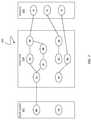
- FIG. 7is a schematic illustration showing an example alert relationship tree with paths that may be traversed according to processing by the controller to determine alert relationships on-the-fly between root causes, symptoms and impacts according to an embodiment of the system described herein.
- FIG. 8is a schematic illustration showing a causality map that may be displayed for the user in response to a query submitted to the controller according to an embodiment of the system described herein.
- FIG. 9is a flow diagram showing processing for on-the-fly alert relationship determinations according to an embodiment of the system described herein.
- FIG. 1is a schematic diagram 20 showing a plurality of hosts 22 a - 22 c coupled to a data storage device 24 that may be used in connection with an embodiment of the system described herein.
- the data storage device 24includes a memory 26 that facilitates operation of the storage device 24 , as further described elsewhere herein.
- the data storage devicealso includes a plurality of host adapters (HA's) 28 a - 28 c that handle reading and writing of data between the hosts 22 a - 22 c and the storage device 24 .
- HA'shost adapters
- the diagram 20shows each of the hosts 22 a - 22 c coupled to each of the HA's 28 a - 28 c , it will be appreciated by one of ordinary skill in the art that one or more of the HA's 28 a - 28 c may be coupled to other hosts.
- the storage device 24may be a Symmetrix storage device and/or a CLARiiON storage device produced by EMC Corporation of Hopkinton, Mass.
- the storage device 24may include one or more Remote Data Facility (RDF) adapter units (RA's) 32 a - 32 c .
- RDFRemote Data Facility
- An RDF product produced by EMC Corporationmay be used to copy data from one storage device to another. For example, if a host writes data to a first storage device (e.g., a local storage device), it may be desirable to copy that data to a second storage device provided in a different location (e.g., a remote storage device).
- the RA's 32 a - 32 care coupled to an RDF link 40 and are similar to the HA's 28 a - 28 c , but are used to transfer data between the storage device 24 and other storage devices that are also coupled to the RDF link 40 .
- the storage device 24may be coupled to additional RDF links (not shown) in addition to the RDF link 40 .
- RDFand the use thereof in data recovery and storage techniques, see, for example, U.S. Pat. No. 5,742,792 to Yanai, et al., entitled “Remote Data Mirroring” and U.S. Pat. No. 7,779,291 to Yoder et al., entitled “Four Site Triangular Asynchronous Replication,” which are incorporated herein by reference.
- the storage device 24may also include one or more disks 36 a - 36 c , each containing a different portion of data stored on the storage device 24 .
- Each of the disks 36 a - 36 cmay be coupled to a corresponding one of a plurality of disk adapter units (DA) 38 a - 38 c that provides data to a corresponding one of the disks 36 a - 36 c and receives data from a corresponding one of the disks 36 a - 36 c .
- the disks 36 a - 36 cmay include any appropriate storage medium or mechanism, including hard disks, solid-state storage (flash memory), etc.
- datamay be appropriately understood, in various embodiments, to refer to data files, extents, blocks, chunks and/or other designations that indicate a unit, segment or collection of data.
- the logical storage space in the storage device 24 that corresponds to the disks 36 a - 36 cmay be subdivided into a plurality of volumes or logical devices.
- the logical devicesmay or may not correspond to the physical storage space of the disks 36 a - 36 c .
- the disk 36 amay contain a plurality of logical devices or, alternatively, a single logical device could span both of the disks 36 a , 36 b .
- the hosts 22 a - 22 emay be configured to access any combination of logical devices independent of the location of the logical devices on the disks 36 a - 36 c .
- a device, such as a logical device described above,has a size or capacity that may be expressed in terms of device geometry.
- the device geometrymay include device geometry parameters regarding the number of cylinders in the device, the number of heads or tracks per cylinder, and the number of blocks per track, and these parameters may be used to identify locations on a disk. Other embodiments may use different
- One or more internal logical data path(s)exist between the DA's 38 a - 38 c , the HA's 28 a - 28 c , the RA's 32 a - 32 c , and the memory 26 .
- one or more internal buses and/or communication modulesmay be used.
- the memory 26may be used to facilitate data transferred between the DA's 38 a - 38 c , the HA's 28 a - 28 c and the RA's 32 a - 32 c .
- the memory 26may contain tasks that are to be performed by one or more of the DA's 38 a - 38 c , the HA's 28 a - 28 c and the RA's 32 a - 32 c and a cache for data fetched from one or more of the disks 36 a - 36 c . Use of the memory 26 is further described elsewhere herein in more detail.
- the storage device 24may be provided as a stand-alone device coupled to the hosts 22 a - 22 c as shown in FIG. 1 or, alternatively, the storage device 24 may be part of, and/or otherwise coupled to, a storage area network (SAN) that may include a plurality of other storage devices as well as switches, routers, network connections, etc., as further discussed elsewhere herein.
- SANstorage area network
- FIG. 2is a schematic diagram 50 illustrating an embodiment of the storage device 24 where each of a plurality of directors 52 a - 52 c are coupled to the memory 26 .
- Each of the directors 52 a - 52 cmay represent one of the HA's 28 a - 28 c , RA's 32 a - 32 c , and/or DA's 38 a - 38 c .
- the diagram 50also shows an optional communication module (CM) 54 that provides an alternative communication path between the directors 52 a - 52 c .
- CMcommunication module
- Each of the directors 52 a - 52 cmay be coupled to the CM 54 so that any one of the directors 52 a - 52 c may send a message and/or data to any other one of the directors 52 a - 52 c without needing to go through the memory 26 .
- the CM 54may be implemented using conventional MUX/router technology where a sending one of the directors 52 a - 52 c provides an appropriate address to cause a message and/or data to be received by an intended receiving one of the directors 52 a - 52 c .
- CM 54may be implemented using one or more of the directors 52 a - 52 c so that, for example, the directors 52 a - 52 c may be interconnected directly with the interconnection functionality being provided on each of the directors 52 a - 52 c .
- a sending one of the directors 52 a - 52 cmay be able to broadcast a message to all of the other directors 52 a - 52 c at the same time.
- one or more of the directors 52 a - 52 cmay have multiple processor systems thereon and thus may be able to perform functions for multiple directors. In some instances, at least one of the directors 52 a - 52 c having multiple processor systems thereon may simultaneously perform the functions of at least two different types of directors (e.g., an HA and a DA). Furthermore, in some embodiments, at least one of the directors 52 a - 52 c having multiple processor systems thereon may simultaneously perform the functions of at least one type of director and perform other processing with the other processing system.
- the memory 26may be a global memory in which all or at least part of the global memory may be provided on one or more of the directors 52 a - 52 c and shared with other ones of the directors 52 a - 52 c .
- the memory 26may be part of a global memory distributed across the processor systems of more than one storage device and accessible by each of the storage devices.
- a storage area networkmay be used to couple one or more host devices with one or more storage devices in a manner that allows reconfiguring connections without having to physically disconnect and reconnect cables from and to ports of the devices.
- a storage area networkmay be implemented using one or more switches to which the storage devices and the host devices are coupled. The switches may be programmed to allow connections between specific ports of devices coupled to the switches. A port that can initiate a data-path connection may be called an “initiator” port while the other port may be deemed a “target” port.
- FIG. 3is a schematic illustration 80 showing a storage area network (SAN) 60 providing a SAN fabric coupling a plurality of host devices (H 1 -HN) 22 a - c to a plurality of storage devices (SD 1 -SDN) 24 a - c .
- Each of the devices 22 a - c , 24 a - cmay have a corresponding port that is physically coupled to switches of the SAN fabric used to implement the storage area network 60 .
- the switchesmay be separately programmed by one of the devices 22 a - c , 24 a - c or by a different device (not shown).
- Programming the switchesmay include setting up specific zones that describe allowable data-path connections (which ports may form a data-path connection) and possible allowable initiator ports of those configurations. For example, there may be a zone for connecting the port of the host 22 a with the port of the storage device 24 a . Upon becoming activated (e.g., powering up), the host 22 a and the storage device 24 a may send appropriate signals to the switch(es) of the storage area network 60 , and each other, which then allows the host 22 a to initiate a data-path connection between the port of the host 22 a and the port of the storage device 24 a . Zones may be defined in terms of a unique identifier associated with each of the ports, such as such as a 64-bit world-wide port name (WWPN).
- WWPNworld-wide port name
- the system described hereinmay be used in connection with performance data collection for data migration and/or data mirroring techniques using a SAN.
- Data transfer among storage devicesmay involve various data synchronization processing and techniques to provide reliable protection copies of data among a source site and a destination site.
- synchronous transfersdata may be transmitted to a remote site and an acknowledgement of a successful write is transmitted synchronously with the completion thereof.
- a data transfer processmay be initiated and a data write may be acknowledged before the data is actually transferred to directors at the remote site.
- Asynchronous transfersmay occur in connection with sites located geographically distant from each other. Asynchronous distances may be distances in which asynchronous transfers are used because synchronous transfers would take more time than is preferable or desired. Examples of data migration and mirroring products includes Symmetrix Remote Data Facility (SRDF) products from EMC Corporation.
- SRDFSymmetrix Remote Data Facility
- FIG. 4is a schematic illustration 82 showing multiple SAN switches of a SAN, like that of FIG. 3 , that may be used in connection with an embodiment of the system described herein.
- the SANis shown with two switches, switch 61 (SW 1 ) and switch 62 (SW 2 ), that are used in connection with an I/O data path 70 from the host 22 a to the storage device 24 a .
- the switches 61 , 62may include physical and/or logical devices.
- switchesare shown, more than two switches and/or other appropriate elements of a SAN fabric may be used in connection with the providing of I/O data paths from one or more of the hosts 22 a - c to one or more of the storages devices 24 a - c in connection with path performance data collection according to the system described herein.
- the selection and/or identification of the I/O path 70may be performed according to multiple selection factors and using known path selection techniques.
- Suitable data storage system simulation toolsthat may be used in connection with the system described herein may include systems and methods like that disclosed in U.S. Pat. No. 7,392,360 to Aharoni et al., entitled “Method and System for Capacity Planning and Configuring One or More Data Storage Systems,” U.S. Pat. No. 7,292,969 to Aharoni et al., entitled “Method and System for Simulating Performance on One or More Storage Systems,” and U.S. patent application Ser. No. 13/065,806 to Smirnov et al., filed Mar. 30, 2011, entitled “Write Pacing Simulation Tool,” which are all assigned to EMC Corporation and which are all incorporated herein by reference.
- FIG. 5is a schematic illustration showing a controller 100 according to an embodiment of the system described herein that may include a console 101 that enables feature control and display.
- the controller 100may provide for user interface control and/or display of aspects of the SAN and components thereof, including performance characteristics and alert relationship analyses, according to various embodiments of the system described herein.
- the controller 100enables determinations of alert relationships “on-the-fly” for alerts affecting multiple causes, symptoms and impacts and including on-the-fly determinations of root causes.
- the on-the-fly determinations of the controller 100provide that the alert relationships may be determined in response to a query or request by the user without requiring the maintaining of a large stored hierarchical relationship structure of alerts.
- the console 101 of the controller 100is shown displaying SAN topology corresponding to one or more I/O data paths for a HOST N of the SAN.
- the console 101may be a RESTful (representational state transfer) interface accessible via the Internet.
- the console 101may include a graphical section 110 that shows a visual topology representation of the SAN and components thereof.
- the section 110graphical displays the host 112 (HOST N), coupled via SAN switches 114 , to one or more storage devices/arrays 116 .
- Section 120may display map details of the SAN elements, for example, performance measures for particular elements of I/O data paths in graph form 122 , 124 , 126 as well as in text or tabulated form 128 .
- the performance measures displayedmay include those discussed elsewhere herein, including workload and performance characteristics such as CPU utilization, memory utilization for the host and IOps (I/O in Mb per sec), response time in ms, throughput in KBps, and queue length for host devices, switches, arrays etc., among other appropriate measures.
- Section 130indicates that multiple types of detail and performance measures may be displayed in various forms for the application host, including features corresponding to the I/O data path attributes, performance, capacity, alerts, connectivity, path details, virtual machine (VM) information, data stores, configuration changes, discovery details and group details.
- a link button 132may be provided to view/edit performance collection settings.
- portion 134indicates that historical or past performance data collection may be maintained by the system. For example, a user may view past performance data collection from the prior day, prior week, prior month and/or any other customizable date range.
- the controller 100may provide for analysis and display of alerts for root causes, symptoms and impacts via a single application control.
- the controller 100may be part of a data collection tool that may provide for collection various types of data concerning performance characteristics of the storage devices and/or other elements of a storage area network (SAN), including I/O data paths, that may be monitored according to various statistics and measures.
- Performance characteristicsmay include, for example, performance data, capacity data, discovery data, including configuration data and/or topology data, among other characteristics.
- Examples of various performance characteristicsmay include CPU utilization, memory utilization for the host and IOps (I/O in Mb per sec), response time in ms, throughput in KBps, discovered hosts of an I/O data path, queue length for host devices, whether the hosts are virtual (e.g., running as guest operating system or a virtual machine (VM)) or not, the hosts' IP addresses, operating systems and versions thereof, whether the host is in a group or cluster, and/or other appropriate performance characteristics.
- IOpsI/O in Mb per sec
- response time in msresponse time in ms
- throughput in KBpsthroughput in KBps
- discovered hosts of an I/O data pathmay include CPU utilization, memory utilization for the host and IOps (I/O in Mb per sec), response time in ms, throughput in KBps, discovered hosts of an I/O data path, queue length for host devices, whether the hosts are virtual (e.g., running as guest operating system or a virtual machine (VM
- the component 100may be an application installed on an application host or other computer providing SAN administration and/or management functionality and/or may be installed on one or more of the hosts 22 a - c coupled to the SAN.
- the component 100may be used in connection with EMC Ionix products, including the EMC Ionix Unified Infrastructure Manager (UIM) and/or EMC Ionix Storage Insight for Availability, produced by EMC Corporation of Hopkinton, Mass.
- EMC Ionix Unified Infrastructure ManagerUAM
- EMC Ionix Storage Insight for Availabilityproduced by EMC Corporation of Hopkinton, Mass.
- Other storage management productsthat may be used in connection with the system described herein may include, for example, EMC's ProSphere product and a Vblock platform product produced by VCE Company, LLC.
- the statistics used by the component 100 according to the system described hereinmay be gathered by the component according to the data collection techniques discussed elsewhere herein.
- the performance data collectionmay be turned on or off from the application host running the tool via a user interface.
- Lim's toolmay automatically (e.g., without user intervention) update performance data collection characteristics as the application host I/O data path changes according to user controlled settings but without requiring further user intervention during the updating.
- Turning on path performance data collection on the application host via the user interfacemay automatically set up synchronized performance data collection for all managed objects within an I/O data path.
- data used in connection with the system described hereinmay obtained using other data collection devices and mechanisms, including products produced by EMC Corporation such as the EMC Workload Analyzer (WLA), the Symmetrix Performance Analyzer (SPA)®, the Symmetrix CLI statistics collection daemon (STP), the Storage Configuration Advisor (SCA) and/or the ProSphere Discovery Engine, among other possible collection devices, applications and/or appliances.
- WLAEMC Workload Analyzer
- SPASymmetrix Performance Analyzer
- STPSymmetrix CLI statistics collection daemon
- SCAStorage Configuration Advisor
- ProSphere Discovery EngineProSphere Discovery Engine
- FIG. 6is a schematic illustration showing another console screen (console 102 ) of the controller 102 , having a similar topology display as that of the console 101 but in which alert relationships for the SAN are illustrated in section 200 of the console 102 according to an embodiment of the system described herein.
- the section 200shows alert relationship information determined on-the-fly according to the system described herein and including symptom information 202 , impact information 204 and causation information 206 , including root causes, in connection with one or more alerts.
- alert attributes informationFor a given alert, according to the system described herein, only immediate relationships may be maintained as alert attributes information. For example, for the case where an alert “A” is a root cause, alerts “B” and “C” are intermediate symptoms and alerts “I 1 ” and “I 2 ” are impacts, a user who receives alert C will have the following information:
- the usermay request further information, for example, using one or more query buttons 210 and/or other appropriate query mechanism submitted via the controller 100 .
- the usermay query the controller 100 to determine the “RootCausedBy” information for the alert C and determine, by traversal of an alert relationship path as further discussed elsewhere herein, that alert A is the root cause of alert C and obtain alert A's properties.
- alert Cis caused by multiple alerts, in which case the controller 100 may traverse all possible alert relationship paths, as further discussed elsewhere herein, and determine all root cause alerts of C.
- a similar algorithmmay be applied in a different direction, for example, to determine impact alerts caused by alert C.
- TABLE 1shows alert relationship information that may be obtained by the controller 100 based on processing according to the system described herein for a use case example in which: A causes B. B causes C. C impacts I 1 and A impacts I 2 .
- FIG. 7is a schematic illustration showing an example alert relationship tree 300 with paths that may be traversed according to processing by the controller 100 to determine alert relationships on-the-fly between root causes 302 , symptoms 304 and impacts 306 according to an embodiment of the system described herein.
- a usermay receive and view alert S 3 of the tree 300 and desire to know the Root Cause alert of the alert S 3 .
- the controller 100determines that S 3 is caused by alerts S 9 and S 2 .
- Processing of the controller 100may then include pushing S 2 onto a stack and/or other appropriate software structure and traversing the tree beginning from node S 9 : specifically, S 9 , S 7 , S 1 and R 1 .
- the controller 100may determine from each alert reached the immediate relationships of that alert in order to continue traversing a particular path of the tree 300 .
- the traversing of paths in the tree 300may be automatic and provide for automated root cause and impact analyses in accordance with the features of the system discussed herein.
- the controller 100determines that R 1 is a root cause alert of alert S 3 and may store this information, e.g., in a RootCauseList. The controller may then pop alert S 2 from the stack, and traverse a path through tree 300 beginning with node S 2 . In this example, the controller 100 will traverse S 2 back through S 1 to R 1 to determine that R 1 is the root cause via the S 2 path. The controller 100 may determine from the RootCauseList that R 1 has already been determined as a root cause for the alert S 3 .
- the controller 100may then return to the requesting user the RootCauseList alerts for S 3 ; specifically, return that R 1 is the root cause alert for alert S 3 . It is noted that a similar algorithm as that noted above may be applied in reverse to determine impact alerts caused by a particular alert.
- the controller 100may traverse the tree 300 in a manner similar to that noted discussed above but in a different direction (e.g., paths beginning with alerts S 5 and S 8 , respectively) to determine that impact alerts 12 and 13 (e.g., which may be stored in a ImpactCausedList) are caused by the alert S 4 .
- FIG. 8is a schematic illustration showing a causality map 400 that may be displayed for the user in response to a query submitted to the controller 100 according to an embodiment of the system described herein.
- the causality map 400may be a display screen of the controller 400 showing determinations of alerts 410 as queried by a user.
- the alerts 410may be shown in a topology view in connection with SAN alert information corresponding to one of more hosts (e.g., HOST N 420 ).
- a map overview section 430 of the causality map 400may provide a visual topology of root cause(s), symptom causality and impact(s) for the one or more hosts, as determined according to processing like that discussed elsewhere herein.
- FIG. 9is a flow diagram 500 showing processing for on-the-fly alert relationship determinations according to an embodiment of the system described herein.
- an alertis received that may, for example, alert a user to the occurrence of a particular error symptom occurring on the SAN.
- processingproceeds to a step 504 where the alert is displayed on an interface of a controller.
- processingproceeds to a test step 506 where it is determined whether a user has requested alert relationship information corresponding to the received alert, for example, the user by activating a query using the interface.
- the alert relationship information queriesmay include requests for one or more root causes of the alert and/or impacts of the alert.
- processingis complete. If, at the test step 506 , it is determined that the user has made no query request for further alert relationship information, then processing is complete. If, at the test step 506 , it is determined that the user has requested alert relationship information then processing proceeds to a step 508 where immediate relationships of the alert are determined.
- the immediate relationshipsmay be include the directly preceding cause of the alert and/or the directly subsequent cause/impact of the alert.
- processingproceeds to a step 510 where an alert relationship path is determined for traversal. For example, to determine a root cause of a received alert, the beginning of the traversal path will be an immediately preceding cause of the received alert. In the case where there are more than one preceding causes, all but one of the causes will be temporarily suspended (e.g., pushed onto a stack and/or other software structure for later retrieval) and the remaining cause will indicate the beginning of the path for traversal. A similar but reverse process may be used for obtaining a desired impact of a received alert.
- processingproceeds to a step 512 where the selected alert relationship path is traversed.
- processingproceeds to a step 514 where desired alert relationship information (e.g., root cause or impact) is obtained and stored.
- desired alert relationship informatione.g., root cause or impact
- processingproceeds to a test step 516 where it is determined if another path exists for received alert. For example, if the received alert was caused by two different alerts, and a first one of the causality alerts was initially used to establish the path for traversal, then the second of the causality alerts may be used to establish another path. Accordingly, if, at the test step 516 , it is determined that another path exists then processing proceeds back to the step 510 to determine the (next) alert relationship path for traversal. For example, the next causality alert may be popped from the software stack where it has been temporarily stored.
- processingproceeds to a step 518 where the obtained and stored alert relationship information is displayed using a console of a controller, for example, responsive to a user's query. After the step 518 , processing is complete.
- the computer readable mediummay include a computer hard drive, ROM, RAM, flash memory, portable computer storage media such as a CD-ROM, a DVD-ROM, a flash drive and/or other drive with, for example, a universal serial bus (USB) interface, and/or any other appropriate tangible or non-transitory computer readable medium or computer memory on which executable code may be stored and executed by a processor.
- a computer hard driveROM
- RAMrandom access memory
- portable computer storage mediasuch as a CD-ROM, a DVD-ROM, a flash drive and/or other drive with, for example, a universal serial bus (USB) interface, and/or any other appropriate tangible or non-transitory computer readable medium or computer memory on which executable code may be stored and executed by a processor.
- USBuniversal serial bus
Landscapes
- Engineering & Computer Science (AREA)
- Theoretical Computer Science (AREA)
- Data Mining & Analysis (AREA)
- Databases & Information Systems (AREA)
- Physics & Mathematics (AREA)
- General Engineering & Computer Science (AREA)
- General Physics & Mathematics (AREA)
- Debugging And Monitoring (AREA)
Abstract
Description
| TABLE 1 |
| Alert Relationship Information |
| A:: | Causes B, I2 | ||
| A:: | CausedBy <Empty> | ||
| A:: | RootCaused by <Empty> | ||
| A:: | Impacts I1, I2 | ||
| B:: | Causes C | ||
| B:: | CausedBy A | ||
| B:: | RootCausedBy A | ||
| B:: | Impacts I1 | ||
| C:: | Causes I1 | ||
| C:: | CausedBy B | ||
| C:: | RootCausedBy A | ||
| C:: | Impacts I1 | ||
| I1:: | Causes <Empty> | ||
| I1:: | CausedBy C | ||
| I1:: | RootCausedBy A | ||
| I1:: | Impacts <Empty> | ||
| I2:: | Causes <Empty> | ||
| I2:: | CausedBy A | ||
| I2:: | RootCausedBy A | ||
| I2:: | Impacts <Empty> | ||
Claims (20)
Priority Applications (1)
| Application Number | Priority Date | Filing Date | Title |
|---|---|---|---|
| US13/435,183US8812542B1 (en) | 2012-03-30 | 2012-03-30 | On-the-fly determining of alert relationships in a distributed system |
Applications Claiming Priority (1)
| Application Number | Priority Date | Filing Date | Title |
|---|---|---|---|
| US13/435,183US8812542B1 (en) | 2012-03-30 | 2012-03-30 | On-the-fly determining of alert relationships in a distributed system |
Publications (1)
| Publication Number | Publication Date |
|---|---|
| US8812542B1true US8812542B1 (en) | 2014-08-19 |
Family
ID=51301814
Family Applications (1)
| Application Number | Title | Priority Date | Filing Date |
|---|---|---|---|
| US13/435,183ActiveUS8812542B1 (en) | 2012-03-30 | 2012-03-30 | On-the-fly determining of alert relationships in a distributed system |
Country Status (1)
| Country | Link |
|---|---|
| US (1) | US8812542B1 (en) |
Cited By (4)
| Publication number | Priority date | Publication date | Assignee | Title |
|---|---|---|---|---|
| US20160249240A1 (en)* | 2015-02-24 | 2016-08-25 | CENX, Inc. | Systems and methods for providing visualization of a telecommunications network topology |
| US9959159B2 (en) | 2016-04-04 | 2018-05-01 | International Business Machines Corporation | Dynamic monitoring and problem resolution |
| US20190004884A1 (en)* | 2017-06-28 | 2019-01-03 | Microsoft Technology Licensing, Llc | Modularized Collaborative Performance Issue Diagnostic System |
| US20190370101A1 (en)* | 2018-06-04 | 2019-12-05 | International Business Machines Corporation | Automated cognitive problem management |
Citations (41)
| Publication number | Priority date | Publication date | Assignee | Title |
|---|---|---|---|---|
| US5206939A (en) | 1990-09-24 | 1993-04-27 | Emc Corporation | System and method for disk mapping and data retrieval |
| US5381470A (en)* | 1991-05-28 | 1995-01-10 | Davox Corporation | Supervisory management center with parameter testing and alerts |
| US5742792A (en) | 1993-04-23 | 1998-04-21 | Emc Corporation | Remote data mirroring |
| US5778394A (en) | 1996-12-23 | 1998-07-07 | Emc Corporation | Space reclamation system and method for use in connection with tape logging system |
| US5845147A (en) | 1996-03-19 | 1998-12-01 | Emc Corporation | Single lock command for an I/O storage system that performs both locking and I/O data operation |
| US5857208A (en) | 1996-05-31 | 1999-01-05 | Emc Corporation | Method and apparatus for performing point in time backup operation in a computer system |
| US20020010765A1 (en)* | 2000-07-21 | 2002-01-24 | John Border | Method and system for prioritizing traffic in a network |
| US6434637B1 (en) | 1998-12-31 | 2002-08-13 | Emc Corporation | Method and apparatus for balancing workloads among paths in a multi-path computer system based on the state of previous I/O operations |
| US20030065986A1 (en)* | 2001-05-09 | 2003-04-03 | Fraenkel Noam A. | Root cause analysis of server system performance degradations |
| US20030065659A1 (en)* | 2001-09-28 | 2003-04-03 | Oracle Corporation | Providing a consistent hierarchical abstraction of relational data |
| US20030093514A1 (en)* | 2001-09-13 | 2003-05-15 | Alfonso De Jesus Valdes | Prioritizing bayes network alerts |
| US6622221B1 (en) | 2000-08-17 | 2003-09-16 | Emc Corporation | Workload analyzer and optimizer integration |
| US20040081310A1 (en)* | 2002-10-25 | 2004-04-29 | Hermann Lueckhoff | Alert modeling |
| US6799199B1 (en)* | 2000-01-11 | 2004-09-28 | The Relegence Corporation | Media monitor system |
| US20050216781A1 (en)* | 2003-04-04 | 2005-09-29 | Computer Associates Think, Inc. | Method and system of alert notification |
| US20050251371A1 (en)* | 2004-05-06 | 2005-11-10 | International Business Machines Corporation | Method and apparatus for visualizing results of root cause analysis on transaction performance data |
| US6965845B2 (en) | 2003-03-31 | 2005-11-15 | Emc Corporation | Method and apparatus for system management using codebook correlation with symptom exclusion |
| US20050283753A1 (en)* | 2003-08-07 | 2005-12-22 | Denise Ho | Alert triggers and event management in a relationship system |
| US20060010119A1 (en)* | 2001-12-28 | 2006-01-12 | International Business Machines Corporation | Real time data warehousing |
| US7003433B2 (en) | 1994-05-25 | 2006-02-21 | Emc Corporation | Apparatus and method for event correlation and problem reporting |
| US7292969B1 (en) | 2002-09-27 | 2007-11-06 | Emc Corporation | Method and system for simulating performance on one or more data storage systems |
| US20070276780A1 (en)* | 2006-05-08 | 2007-11-29 | Fujitsu Limited | Monitoring system |
| US20080133552A1 (en)* | 2004-09-24 | 2008-06-05 | Advanced Forensic Solutions Limited | Information Processor Arrangement |
| US20080147646A1 (en)* | 2002-02-07 | 2008-06-19 | The Relegence Corporation | Method for real time relevancy determination of terms |
| US7392360B1 (en) | 2002-09-27 | 2008-06-24 | Emc Corporation | Method and system for capacity planning and configuring one or more data storage systems |
| US20080208953A1 (en)* | 2005-10-26 | 2008-08-28 | Huawei Technologies Co., Ltd. | Method for notifying presence information, a presence server, a client and a system |
| US7441023B2 (en) | 2003-09-25 | 2008-10-21 | Emc Corporation | Method and apparatus for modeling and analyzing MPLS and virtual private networks |
| US20080263009A1 (en)* | 2007-04-19 | 2008-10-23 | Buettner Raymond R | System and method for sharing of search query information across organizational boundaries |
| US20080270380A1 (en)* | 2005-05-06 | 2008-10-30 | Aleksander Ohrn | Method for Determining Contextual Summary Information Across Documents |
| US7529181B2 (en) | 2004-12-07 | 2009-05-05 | Emc Corporation | Method and apparatus for adaptive monitoring and management of distributed systems |
| US7680951B1 (en)* | 2004-06-01 | 2010-03-16 | Massachusetts Institute Of Technology | High speed subscribe-and-alert service using content graphs |
| US7688753B1 (en) | 2007-12-28 | 2010-03-30 | Emc Corporation | Selection of a data path based on one or more performance characteristics of a computer system |
| US7720003B2 (en) | 2003-09-25 | 2010-05-18 | Emc Corporation | Model-based method and apparatus for determining MPLS network properties |
| US7779291B2 (en) | 2006-12-29 | 2010-08-17 | Emc Corporation | Four site triangular asynchronous replication |
| US20110016114A1 (en)* | 2009-07-17 | 2011-01-20 | Thomas Bradley Allen | Probabilistic link strength reduction |
| US20110029882A1 (en)* | 2009-07-31 | 2011-02-03 | Devendra Rajkumar Jaisinghani | Cloud computing: unified management console for services and resources in a data center |
| US20110115649A1 (en)* | 2009-11-18 | 2011-05-19 | Honeywell International Inc. | Intelligent crew alerting system and method for aircraft and other vehicle applications |
| US8028062B1 (en) | 2007-12-26 | 2011-09-27 | Emc Corporation | Non-disruptive data mobility using virtual storage area networks with split-path virtualization |
| US8032621B1 (en)* | 2006-01-03 | 2011-10-04 | Emc Corporation | Methods and apparatus providing root cause analysis on alerts |
| US20120124503A1 (en)* | 2010-11-11 | 2012-05-17 | Sap Ag | Method and system for easy correlation between monitored metrics and alerts |
| US20120304022A1 (en)* | 2011-05-24 | 2012-11-29 | International Business Machines Corporation | Configurable Alert Delivery In A Distributed Processing System |
- 2012
- 2012-03-30USUS13/435,183patent/US8812542B1/enactiveActive
Patent Citations (42)
| Publication number | Priority date | Publication date | Assignee | Title |
|---|---|---|---|---|
| US5206939A (en) | 1990-09-24 | 1993-04-27 | Emc Corporation | System and method for disk mapping and data retrieval |
| US5381470A (en)* | 1991-05-28 | 1995-01-10 | Davox Corporation | Supervisory management center with parameter testing and alerts |
| US5742792A (en) | 1993-04-23 | 1998-04-21 | Emc Corporation | Remote data mirroring |
| US7003433B2 (en) | 1994-05-25 | 2006-02-21 | Emc Corporation | Apparatus and method for event correlation and problem reporting |
| US5845147A (en) | 1996-03-19 | 1998-12-01 | Emc Corporation | Single lock command for an I/O storage system that performs both locking and I/O data operation |
| US5857208A (en) | 1996-05-31 | 1999-01-05 | Emc Corporation | Method and apparatus for performing point in time backup operation in a computer system |
| US5778394A (en) | 1996-12-23 | 1998-07-07 | Emc Corporation | Space reclamation system and method for use in connection with tape logging system |
| US6434637B1 (en) | 1998-12-31 | 2002-08-13 | Emc Corporation | Method and apparatus for balancing workloads among paths in a multi-path computer system based on the state of previous I/O operations |
| US6799199B1 (en)* | 2000-01-11 | 2004-09-28 | The Relegence Corporation | Media monitor system |
| US20020010765A1 (en)* | 2000-07-21 | 2002-01-24 | John Border | Method and system for prioritizing traffic in a network |
| US6622221B1 (en) | 2000-08-17 | 2003-09-16 | Emc Corporation | Workload analyzer and optimizer integration |
| US20030065986A1 (en)* | 2001-05-09 | 2003-04-03 | Fraenkel Noam A. | Root cause analysis of server system performance degradations |
| US20030093514A1 (en)* | 2001-09-13 | 2003-05-15 | Alfonso De Jesus Valdes | Prioritizing bayes network alerts |
| US20030065659A1 (en)* | 2001-09-28 | 2003-04-03 | Oracle Corporation | Providing a consistent hierarchical abstraction of relational data |
| US20060010119A1 (en)* | 2001-12-28 | 2006-01-12 | International Business Machines Corporation | Real time data warehousing |
| US20080147646A1 (en)* | 2002-02-07 | 2008-06-19 | The Relegence Corporation | Method for real time relevancy determination of terms |
| US7292969B1 (en) | 2002-09-27 | 2007-11-06 | Emc Corporation | Method and system for simulating performance on one or more data storage systems |
| US7392360B1 (en) | 2002-09-27 | 2008-06-24 | Emc Corporation | Method and system for capacity planning and configuring one or more data storage systems |
| US20040081310A1 (en)* | 2002-10-25 | 2004-04-29 | Hermann Lueckhoff | Alert modeling |
| US6965845B2 (en) | 2003-03-31 | 2005-11-15 | Emc Corporation | Method and apparatus for system management using codebook correlation with symptom exclusion |
| US20050216781A1 (en)* | 2003-04-04 | 2005-09-29 | Computer Associates Think, Inc. | Method and system of alert notification |
| US20050283753A1 (en)* | 2003-08-07 | 2005-12-22 | Denise Ho | Alert triggers and event management in a relationship system |
| US7783778B2 (en) | 2003-09-25 | 2010-08-24 | Emc Corporation | Model-based method and apparatus for determining virtual private network topologies |
| US7720003B2 (en) | 2003-09-25 | 2010-05-18 | Emc Corporation | Model-based method and apparatus for determining MPLS network properties |
| US7441023B2 (en) | 2003-09-25 | 2008-10-21 | Emc Corporation | Method and apparatus for modeling and analyzing MPLS and virtual private networks |
| US20050251371A1 (en)* | 2004-05-06 | 2005-11-10 | International Business Machines Corporation | Method and apparatus for visualizing results of root cause analysis on transaction performance data |
| US7680951B1 (en)* | 2004-06-01 | 2010-03-16 | Massachusetts Institute Of Technology | High speed subscribe-and-alert service using content graphs |
| US20080133552A1 (en)* | 2004-09-24 | 2008-06-05 | Advanced Forensic Solutions Limited | Information Processor Arrangement |
| US7529181B2 (en) | 2004-12-07 | 2009-05-05 | Emc Corporation | Method and apparatus for adaptive monitoring and management of distributed systems |
| US20080270380A1 (en)* | 2005-05-06 | 2008-10-30 | Aleksander Ohrn | Method for Determining Contextual Summary Information Across Documents |
| US20080208953A1 (en)* | 2005-10-26 | 2008-08-28 | Huawei Technologies Co., Ltd. | Method for notifying presence information, a presence server, a client and a system |
| US8032621B1 (en)* | 2006-01-03 | 2011-10-04 | Emc Corporation | Methods and apparatus providing root cause analysis on alerts |
| US20070276780A1 (en)* | 2006-05-08 | 2007-11-29 | Fujitsu Limited | Monitoring system |
| US7779291B2 (en) | 2006-12-29 | 2010-08-17 | Emc Corporation | Four site triangular asynchronous replication |
| US20080263009A1 (en)* | 2007-04-19 | 2008-10-23 | Buettner Raymond R | System and method for sharing of search query information across organizational boundaries |
| US8028062B1 (en) | 2007-12-26 | 2011-09-27 | Emc Corporation | Non-disruptive data mobility using virtual storage area networks with split-path virtualization |
| US7688753B1 (en) | 2007-12-28 | 2010-03-30 | Emc Corporation | Selection of a data path based on one or more performance characteristics of a computer system |
| US20110016114A1 (en)* | 2009-07-17 | 2011-01-20 | Thomas Bradley Allen | Probabilistic link strength reduction |
| US20110029882A1 (en)* | 2009-07-31 | 2011-02-03 | Devendra Rajkumar Jaisinghani | Cloud computing: unified management console for services and resources in a data center |
| US20110115649A1 (en)* | 2009-11-18 | 2011-05-19 | Honeywell International Inc. | Intelligent crew alerting system and method for aircraft and other vehicle applications |
| US20120124503A1 (en)* | 2010-11-11 | 2012-05-17 | Sap Ag | Method and system for easy correlation between monitored metrics and alerts |
| US20120304022A1 (en)* | 2011-05-24 | 2012-11-29 | International Business Machines Corporation | Configurable Alert Delivery In A Distributed Processing System |
Non-Patent Citations (23)
| Title |
|---|
| Alert Correlation in a Cooperative Intrusion Detection Frramework, Cuppens et al, Proceedings of the 2002 IEEE Symposium on Security and Privacy (S&P'02), 2002.* |
| An IDS Alert Fusion Approach Based on Happened Before Relation, Xu et al., IEEE, 2008.* |
| Building network attack graph for alert casual correlation, Zhang et al., Computer & Security, 27, pp. 188-196, 2008.* |
| Clustering Intrusion Detection Alarms to Support Root Cause Analysis, Julisch et al, ACM Transaction on Information and System Security, 6(4), pp. 443-471, Nov. 2003.* |
| Construct Efficient Hyper-Alert Correlation for Defense-in-Depth Network Security System, Huang et al, LNCS 3090, pp. 886-894, 2004.* |
| EMC Corporation, "Diagnosing Performance Issues With ProSphere: An Introduction to Use Cases and Architecture," White Paper H8935, Sep. 2011, 14 pp. |
| EMC Corporation, "EMC Ionix ControlCenter (formerly EMC ControlCenter) 6.0 StorageScope: Best Practices Planning," White Paper H4154, Jun. 2009, 43 pp. |
| EMC Corporation, "EMC Ionix Storage Insight for Availability," Data Sheet S0059.2, May 2009, 4 pp. |
| EMC Corporation, "EMC Ionix Unified Infrastructure Manager/Operations: Centralized visibility into VCE Vblock Infrastructure Platforms and Their Availability," Data Sheet H8713.2, Nov. 2011, 2 pp. |
| EMC Corporation, "EMC Smarts IP Availibility Manager: Technology for IP Network Management, Including Network-Attached Storage," White Paper S0051, Nov. 2005, 9 pp. |
| EMC Corporation, "EMC Symmetrix Storage Management Solution," Data Sheet H6194.2, Nov. 2010, 5 pp. |
| EMC Corporation, "ProSphere Discovery and Monitoring for the Modern Data Center," White Paper H8890, Aug. 2011, 17 pp. |
| EMC Corporation, "ProSphere: Next Generation Storage Resource Management," White Paper H8886, Aug. 2011, 13 pp. |
| Information Alert in Distributed Digital Libraries: The Models, Languages, and Architecture of DIAS, Koubarakis et al EECDL, LNCS 2458, pp. 527-542, 2002.* |
| Keeping Track of 70,000+ Servers, The Akamai Query System, Cohen et al., Proceedings of the 24th international conference on Large installation system administration (LISA), 2010.* |
| Problem Determination Using Dependency Graphs Run-Time Behavior Models, Agarwal et al., DSOM, International Federation for Information Processing, LNCS 3278, pp. 171-182, 2004.* |
| U.S. Appl. No. 12/807,943, filed Sep. 17, 2010, Colon et al. |
| U.S. Appl. No. 13/065,806, filed Mar. 30, 2011, Smirnov et al. |
| U.S. Appl. No. 13/335,316, filed Dec. 22, 2011, Lim et al. |
| VCE Company, "Automated Monitoring and Event Recovery of Vblock(TM) Infrastructure Platforms with IPSoft Managed Service," White Paper, May 2011, 20 pp. |
| VCE Company, "Automated Monitoring and Event Recovery of Vblock™ Infrastructure Platforms with IPSoft Managed Service," White Paper, May 2011, 20 pp. |
| VCE Company, "Simplifying Incident and Problem Management with Vblock(TM) Infrastructure Platforms," White Paper, Feb. 2011, 18 pp. |
| VCE Company, "Simplifying Incident and Problem Management with Vblock™ Infrastructure Platforms," White Paper, Feb. 2011, 18 pp. |
Cited By (8)
| Publication number | Priority date | Publication date | Assignee | Title |
|---|---|---|---|---|
| US20160249240A1 (en)* | 2015-02-24 | 2016-08-25 | CENX, Inc. | Systems and methods for providing visualization of a telecommunications network topology |
| US10200893B2 (en)* | 2015-02-24 | 2019-02-05 | CENX, Inc. | Systems and methods for providing visualization of a telecommunications network topology |
| US9959159B2 (en) | 2016-04-04 | 2018-05-01 | International Business Machines Corporation | Dynamic monitoring and problem resolution |
| US10169136B2 (en) | 2016-04-04 | 2019-01-01 | International Business Machines Corporation | Dynamic monitoring and problem resolution |
| US20190004884A1 (en)* | 2017-06-28 | 2019-01-03 | Microsoft Technology Licensing, Llc | Modularized Collaborative Performance Issue Diagnostic System |
| US10565045B2 (en)* | 2017-06-28 | 2020-02-18 | Microsoft Technology Licensing, Llc | Modularized collaborative performance issue diagnostic system |
| US20190370101A1 (en)* | 2018-06-04 | 2019-12-05 | International Business Machines Corporation | Automated cognitive problem management |
| US11086708B2 (en)* | 2018-06-04 | 2021-08-10 | International Business Machines Corporation | Automated cognitive multi-component problem management |
Similar Documents
| Publication | Publication Date | Title |
|---|---|---|
| US8825919B1 (en) | Path performance data collection | |
| US8832498B1 (en) | Scalable codebook correlation for cloud scale topology | |
| US10320604B1 (en) | Sending alerts from cloud computing systems | |
| US9736046B1 (en) | Path analytics using codebook correlation | |
| US9495409B1 (en) | Techniques for performing data validation | |
| JP6734866B2 (en) | Resynchronization to the first storage system after failover to the second storage system that mirrors the first storage system | |
| US9460136B1 (en) | Managing databases in data storage systems | |
| JP4391265B2 (en) | Storage subsystem and performance tuning method | |
| EP3385833B1 (en) | Data path monitoring within a distributed storage network | |
| US8117387B2 (en) | Storage system and method of managing a storage system using a management apparatus | |
| US8261125B2 (en) | Global write-log device for managing write logs of nodes of a cluster storage system | |
| US6598174B1 (en) | Method and apparatus for storage unit replacement in non-redundant array | |
| US7558916B2 (en) | Storage system, data processing method and storage apparatus | |
| US9927980B1 (en) | Accessing point in time versions of a logical device in connection with I/O operations | |
| US8856079B1 (en) | Application programming interface for efficient object information gathering and listing | |
| US9779120B1 (en) | Native storage data collection using plug-ins that are independent from data sources | |
| US8046446B1 (en) | System and method for providing availability using volume server sets in a storage environment employing distributed block virtualization | |
| US8346788B1 (en) | Techniques for mapping data models using an intermediate processing layer | |
| US8601025B1 (en) | Techniques using a bidirectional graph for reporting to clients | |
| JP4744955B2 (en) | Data management system | |
| CN104838367A (en) | Method and apparatus of disaster recovery virtualization | |
| JP5000234B2 (en) | Control device | |
| JP2006268398A (en) | Computer system, data management method and program | |
| US8812542B1 (en) | On-the-fly determining of alert relationships in a distributed system | |
| US9417817B2 (en) | Management apparatus and management method |
Legal Events
| Date | Code | Title | Description |
|---|---|---|---|
| AS | Assignment | Owner name:EMC CORPORATION, MASSACHUSETTS Free format text:ASSIGNMENT OF ASSIGNORS INTEREST;ASSIGNORS:SARING, ALIK;LAM, CHEUK;SIGNING DATES FROM 20120328 TO 20120329;REEL/FRAME:027964/0619 | |
| STCF | Information on status: patent grant | Free format text:PATENTED CASE | |
| AS | Assignment | Owner name:CREDIT SUISSE AG, CAYMAN ISLANDS BRANCH, AS COLLATERAL AGENT, NORTH CAROLINA Free format text:SECURITY AGREEMENT;ASSIGNORS:ASAP SOFTWARE EXPRESS, INC.;AVENTAIL LLC;CREDANT TECHNOLOGIES, INC.;AND OTHERS;REEL/FRAME:040134/0001 Effective date:20160907 Owner name:THE BANK OF NEW YORK MELLON TRUST COMPANY, N.A., AS NOTES COLLATERAL AGENT, TEXAS Free format text:SECURITY AGREEMENT;ASSIGNORS:ASAP SOFTWARE EXPRESS, INC.;AVENTAIL LLC;CREDANT TECHNOLOGIES, INC.;AND OTHERS;REEL/FRAME:040136/0001 Effective date:20160907 Owner name:CREDIT SUISSE AG, CAYMAN ISLANDS BRANCH, AS COLLAT Free format text:SECURITY AGREEMENT;ASSIGNORS:ASAP SOFTWARE EXPRESS, INC.;AVENTAIL LLC;CREDANT TECHNOLOGIES, INC.;AND OTHERS;REEL/FRAME:040134/0001 Effective date:20160907 Owner name:THE BANK OF NEW YORK MELLON TRUST COMPANY, N.A., A Free format text:SECURITY AGREEMENT;ASSIGNORS:ASAP SOFTWARE EXPRESS, INC.;AVENTAIL LLC;CREDANT TECHNOLOGIES, INC.;AND OTHERS;REEL/FRAME:040136/0001 Effective date:20160907 | |
| AS | Assignment | Owner name:EMC IP HOLDING COMPANY LLC, MASSACHUSETTS Free format text:ASSIGNMENT OF ASSIGNORS INTEREST;ASSIGNOR:EMC CORPORATION;REEL/FRAME:040203/0001 Effective date:20160906 | |
| MAFP | Maintenance fee payment | Free format text:PAYMENT OF MAINTENANCE FEE, 4TH YEAR, LARGE ENTITY (ORIGINAL EVENT CODE: M1551) Year of fee payment:4 | |
| AS | Assignment | Owner name:THE BANK OF NEW YORK MELLON TRUST COMPANY, N.A., T Free format text:SECURITY AGREEMENT;ASSIGNORS:CREDANT TECHNOLOGIES, INC.;DELL INTERNATIONAL L.L.C.;DELL MARKETING L.P.;AND OTHERS;REEL/FRAME:049452/0223 Effective date:20190320 Owner name:THE BANK OF NEW YORK MELLON TRUST COMPANY, N.A., TEXAS Free format text:SECURITY AGREEMENT;ASSIGNORS:CREDANT TECHNOLOGIES, INC.;DELL INTERNATIONAL L.L.C.;DELL MARKETING L.P.;AND OTHERS;REEL/FRAME:049452/0223 Effective date:20190320 | |
| AS | Assignment | Owner name:THE BANK OF NEW YORK MELLON TRUST COMPANY, N.A., TEXAS Free format text:SECURITY AGREEMENT;ASSIGNORS:CREDANT TECHNOLOGIES INC.;DELL INTERNATIONAL L.L.C.;DELL MARKETING L.P.;AND OTHERS;REEL/FRAME:053546/0001 Effective date:20200409 | |
| AS | Assignment | Owner name:WYSE TECHNOLOGY L.L.C., CALIFORNIA Free format text:RELEASE BY SECURED PARTY;ASSIGNOR:CREDIT SUISSE AG, CAYMAN ISLANDS BRANCH;REEL/FRAME:058216/0001 Effective date:20211101 Owner name:SCALEIO LLC, MASSACHUSETTS Free format text:RELEASE BY SECURED PARTY;ASSIGNOR:CREDIT SUISSE AG, CAYMAN ISLANDS BRANCH;REEL/FRAME:058216/0001 Effective date:20211101 Owner name:MOZY, INC., WASHINGTON Free format text:RELEASE BY SECURED PARTY;ASSIGNOR:CREDIT SUISSE AG, CAYMAN ISLANDS BRANCH;REEL/FRAME:058216/0001 Effective date:20211101 Owner name:MAGINATICS LLC, CALIFORNIA Free format text:RELEASE BY SECURED PARTY;ASSIGNOR:CREDIT SUISSE AG, CAYMAN ISLANDS BRANCH;REEL/FRAME:058216/0001 Effective date:20211101 Owner name:FORCE10 NETWORKS, INC., CALIFORNIA Free format text:RELEASE BY SECURED PARTY;ASSIGNOR:CREDIT SUISSE AG, CAYMAN ISLANDS BRANCH;REEL/FRAME:058216/0001 Effective date:20211101 Owner name:EMC IP HOLDING COMPANY LLC, TEXAS Free format text:RELEASE BY SECURED PARTY;ASSIGNOR:CREDIT SUISSE AG, CAYMAN ISLANDS BRANCH;REEL/FRAME:058216/0001 Effective date:20211101 Owner name:EMC CORPORATION, MASSACHUSETTS Free format text:RELEASE BY SECURED PARTY;ASSIGNOR:CREDIT SUISSE AG, CAYMAN ISLANDS BRANCH;REEL/FRAME:058216/0001 Effective date:20211101 Owner name:DELL SYSTEMS CORPORATION, TEXAS Free format text:RELEASE BY SECURED PARTY;ASSIGNOR:CREDIT SUISSE AG, CAYMAN ISLANDS BRANCH;REEL/FRAME:058216/0001 Effective date:20211101 Owner name:DELL SOFTWARE INC., CALIFORNIA Free format text:RELEASE BY SECURED PARTY;ASSIGNOR:CREDIT SUISSE AG, CAYMAN ISLANDS BRANCH;REEL/FRAME:058216/0001 Effective date:20211101 Owner name:DELL PRODUCTS L.P., TEXAS Free format text:RELEASE BY SECURED PARTY;ASSIGNOR:CREDIT SUISSE AG, CAYMAN ISLANDS BRANCH;REEL/FRAME:058216/0001 Effective date:20211101 Owner name:DELL MARKETING L.P., TEXAS Free format text:RELEASE BY SECURED PARTY;ASSIGNOR:CREDIT SUISSE AG, CAYMAN ISLANDS BRANCH;REEL/FRAME:058216/0001 Effective date:20211101 Owner name:DELL INTERNATIONAL, L.L.C., TEXAS Free format text:RELEASE BY SECURED PARTY;ASSIGNOR:CREDIT SUISSE AG, CAYMAN ISLANDS BRANCH;REEL/FRAME:058216/0001 Effective date:20211101 Owner name:DELL USA L.P., TEXAS Free format text:RELEASE BY SECURED PARTY;ASSIGNOR:CREDIT SUISSE AG, CAYMAN ISLANDS BRANCH;REEL/FRAME:058216/0001 Effective date:20211101 Owner name:CREDANT TECHNOLOGIES, INC., TEXAS Free format text:RELEASE BY SECURED PARTY;ASSIGNOR:CREDIT SUISSE AG, CAYMAN ISLANDS BRANCH;REEL/FRAME:058216/0001 Effective date:20211101 Owner name:AVENTAIL LLC, CALIFORNIA Free format text:RELEASE BY SECURED PARTY;ASSIGNOR:CREDIT SUISSE AG, CAYMAN ISLANDS BRANCH;REEL/FRAME:058216/0001 Effective date:20211101 Owner name:ASAP SOFTWARE EXPRESS, INC., ILLINOIS Free format text:RELEASE BY SECURED PARTY;ASSIGNOR:CREDIT SUISSE AG, CAYMAN ISLANDS BRANCH;REEL/FRAME:058216/0001 Effective date:20211101 | |
| MAFP | Maintenance fee payment | Free format text:PAYMENT OF MAINTENANCE FEE, 8TH YEAR, LARGE ENTITY (ORIGINAL EVENT CODE: M1552); ENTITY STATUS OF PATENT OWNER: LARGE ENTITY Year of fee payment:8 | |
| AS | Assignment | Owner name:SCALEIO LLC, MASSACHUSETTS Free format text:RELEASE OF SECURITY INTEREST IN PATENTS PREVIOUSLY RECORDED AT REEL/FRAME (040136/0001);ASSIGNOR:THE BANK OF NEW YORK MELLON TRUST COMPANY, N.A., AS NOTES COLLATERAL AGENT;REEL/FRAME:061324/0001 Effective date:20220329 Owner name:EMC IP HOLDING COMPANY LLC (ON BEHALF OF ITSELF AND AS SUCCESSOR-IN-INTEREST TO MOZY, INC.), TEXAS Free format text:RELEASE OF SECURITY INTEREST IN PATENTS PREVIOUSLY RECORDED AT REEL/FRAME (040136/0001);ASSIGNOR:THE BANK OF NEW YORK MELLON TRUST COMPANY, N.A., AS NOTES COLLATERAL AGENT;REEL/FRAME:061324/0001 Effective date:20220329 Owner name:EMC CORPORATION (ON BEHALF OF ITSELF AND AS SUCCESSOR-IN-INTEREST TO MAGINATICS LLC), MASSACHUSETTS Free format text:RELEASE OF SECURITY INTEREST IN PATENTS PREVIOUSLY RECORDED AT REEL/FRAME (040136/0001);ASSIGNOR:THE BANK OF NEW YORK MELLON TRUST COMPANY, N.A., AS NOTES COLLATERAL AGENT;REEL/FRAME:061324/0001 Effective date:20220329 Owner name:DELL MARKETING CORPORATION (SUCCESSOR-IN-INTEREST TO FORCE10 NETWORKS, INC. AND WYSE TECHNOLOGY L.L.C.), TEXAS Free format text:RELEASE OF SECURITY INTEREST IN PATENTS PREVIOUSLY RECORDED AT REEL/FRAME (040136/0001);ASSIGNOR:THE BANK OF NEW YORK MELLON TRUST COMPANY, N.A., AS NOTES COLLATERAL AGENT;REEL/FRAME:061324/0001 Effective date:20220329 Owner name:DELL PRODUCTS L.P., TEXAS Free format text:RELEASE OF SECURITY INTEREST IN PATENTS PREVIOUSLY RECORDED AT REEL/FRAME (040136/0001);ASSIGNOR:THE BANK OF NEW YORK MELLON TRUST COMPANY, N.A., AS NOTES COLLATERAL AGENT;REEL/FRAME:061324/0001 Effective date:20220329 Owner name:DELL INTERNATIONAL L.L.C., TEXAS Free format text:RELEASE OF SECURITY INTEREST IN PATENTS PREVIOUSLY RECORDED AT REEL/FRAME (040136/0001);ASSIGNOR:THE BANK OF NEW YORK MELLON TRUST COMPANY, N.A., AS NOTES COLLATERAL AGENT;REEL/FRAME:061324/0001 Effective date:20220329 Owner name:DELL USA L.P., TEXAS Free format text:RELEASE OF SECURITY INTEREST IN PATENTS PREVIOUSLY RECORDED AT REEL/FRAME (040136/0001);ASSIGNOR:THE BANK OF NEW YORK MELLON TRUST COMPANY, N.A., AS NOTES COLLATERAL AGENT;REEL/FRAME:061324/0001 Effective date:20220329 Owner name:DELL MARKETING L.P. (ON BEHALF OF ITSELF AND AS SUCCESSOR-IN-INTEREST TO CREDANT TECHNOLOGIES, INC.), TEXAS Free format text:RELEASE OF SECURITY INTEREST IN PATENTS PREVIOUSLY RECORDED AT REEL/FRAME (040136/0001);ASSIGNOR:THE BANK OF NEW YORK MELLON TRUST COMPANY, N.A., AS NOTES COLLATERAL AGENT;REEL/FRAME:061324/0001 Effective date:20220329 Owner name:DELL MARKETING CORPORATION (SUCCESSOR-IN-INTEREST TO ASAP SOFTWARE EXPRESS, INC.), TEXAS Free format text:RELEASE OF SECURITY INTEREST IN PATENTS PREVIOUSLY RECORDED AT REEL/FRAME (040136/0001);ASSIGNOR:THE BANK OF NEW YORK MELLON TRUST COMPANY, N.A., AS NOTES COLLATERAL AGENT;REEL/FRAME:061324/0001 Effective date:20220329 | |
| AS | Assignment | Owner name:SCALEIO LLC, MASSACHUSETTS Free format text:RELEASE OF SECURITY INTEREST IN PATENTS PREVIOUSLY RECORDED AT REEL/FRAME (045455/0001);ASSIGNOR:THE BANK OF NEW YORK MELLON TRUST COMPANY, N.A., AS NOTES COLLATERAL AGENT;REEL/FRAME:061753/0001 Effective date:20220329 Owner name:EMC IP HOLDING COMPANY LLC (ON BEHALF OF ITSELF AND AS SUCCESSOR-IN-INTEREST TO MOZY, INC.), TEXAS Free format text:RELEASE OF SECURITY INTEREST IN PATENTS PREVIOUSLY RECORDED AT REEL/FRAME (045455/0001);ASSIGNOR:THE BANK OF NEW YORK MELLON TRUST COMPANY, N.A., AS NOTES COLLATERAL AGENT;REEL/FRAME:061753/0001 Effective date:20220329 Owner name:EMC CORPORATION (ON BEHALF OF ITSELF AND AS SUCCESSOR-IN-INTEREST TO MAGINATICS LLC), MASSACHUSETTS Free format text:RELEASE OF SECURITY INTEREST IN PATENTS PREVIOUSLY RECORDED AT REEL/FRAME (045455/0001);ASSIGNOR:THE BANK OF NEW YORK MELLON TRUST COMPANY, N.A., AS NOTES COLLATERAL AGENT;REEL/FRAME:061753/0001 Effective date:20220329 Owner name:DELL MARKETING CORPORATION (SUCCESSOR-IN-INTEREST TO FORCE10 NETWORKS, INC. AND WYSE TECHNOLOGY L.L.C.), TEXAS Free format text:RELEASE OF SECURITY INTEREST IN PATENTS PREVIOUSLY RECORDED AT REEL/FRAME (045455/0001);ASSIGNOR:THE BANK OF NEW YORK MELLON TRUST COMPANY, N.A., AS NOTES COLLATERAL AGENT;REEL/FRAME:061753/0001 Effective date:20220329 Owner name:DELL PRODUCTS L.P., TEXAS Free format text:RELEASE OF SECURITY INTEREST IN PATENTS PREVIOUSLY RECORDED AT REEL/FRAME (045455/0001);ASSIGNOR:THE BANK OF NEW YORK MELLON TRUST COMPANY, N.A., AS NOTES COLLATERAL AGENT;REEL/FRAME:061753/0001 Effective date:20220329 Owner name:DELL INTERNATIONAL L.L.C., TEXAS Free format text:RELEASE OF SECURITY INTEREST IN PATENTS PREVIOUSLY RECORDED AT REEL/FRAME (045455/0001);ASSIGNOR:THE BANK OF NEW YORK MELLON TRUST COMPANY, N.A., AS NOTES COLLATERAL AGENT;REEL/FRAME:061753/0001 Effective date:20220329 Owner name:DELL USA L.P., TEXAS Free format text:RELEASE OF SECURITY INTEREST IN PATENTS PREVIOUSLY RECORDED AT REEL/FRAME (045455/0001);ASSIGNOR:THE BANK OF NEW YORK MELLON TRUST COMPANY, N.A., AS NOTES COLLATERAL AGENT;REEL/FRAME:061753/0001 Effective date:20220329 Owner name:DELL MARKETING L.P. (ON BEHALF OF ITSELF AND AS SUCCESSOR-IN-INTEREST TO CREDANT TECHNOLOGIES, INC.), TEXAS Free format text:RELEASE OF SECURITY INTEREST IN PATENTS PREVIOUSLY RECORDED AT REEL/FRAME (045455/0001);ASSIGNOR:THE BANK OF NEW YORK MELLON TRUST COMPANY, N.A., AS NOTES COLLATERAL AGENT;REEL/FRAME:061753/0001 Effective date:20220329 Owner name:DELL MARKETING CORPORATION (SUCCESSOR-IN-INTEREST TO ASAP SOFTWARE EXPRESS, INC.), TEXAS Free format text:RELEASE OF SECURITY INTEREST IN PATENTS PREVIOUSLY RECORDED AT REEL/FRAME (045455/0001);ASSIGNOR:THE BANK OF NEW YORK MELLON TRUST COMPANY, N.A., AS NOTES COLLATERAL AGENT;REEL/FRAME:061753/0001 Effective date:20220329 | |
| AS | Assignment | Owner name:DELL MARKETING L.P. (ON BEHALF OF ITSELF AND AS SUCCESSOR-IN-INTEREST TO CREDANT TECHNOLOGIES, INC.), TEXAS Free format text:RELEASE OF SECURITY INTEREST IN PATENTS PREVIOUSLY RECORDED AT REEL/FRAME (053546/0001);ASSIGNOR:THE BANK OF NEW YORK MELLON TRUST COMPANY, N.A., AS NOTES COLLATERAL AGENT;REEL/FRAME:071642/0001 Effective date:20220329 Owner name:DELL INTERNATIONAL L.L.C., TEXAS Free format text:RELEASE OF SECURITY INTEREST IN PATENTS PREVIOUSLY RECORDED AT REEL/FRAME (053546/0001);ASSIGNOR:THE BANK OF NEW YORK MELLON TRUST COMPANY, N.A., AS NOTES COLLATERAL AGENT;REEL/FRAME:071642/0001 Effective date:20220329 Owner name:DELL PRODUCTS L.P., TEXAS Free format text:RELEASE OF SECURITY INTEREST IN PATENTS PREVIOUSLY RECORDED AT REEL/FRAME (053546/0001);ASSIGNOR:THE BANK OF NEW YORK MELLON TRUST COMPANY, N.A., AS NOTES COLLATERAL AGENT;REEL/FRAME:071642/0001 Effective date:20220329 Owner name:DELL USA L.P., TEXAS Free format text:RELEASE OF SECURITY INTEREST IN PATENTS PREVIOUSLY RECORDED AT REEL/FRAME (053546/0001);ASSIGNOR:THE BANK OF NEW YORK MELLON TRUST COMPANY, N.A., AS NOTES COLLATERAL AGENT;REEL/FRAME:071642/0001 Effective date:20220329 Owner name:EMC CORPORATION, MASSACHUSETTS Free format text:RELEASE OF SECURITY INTEREST IN PATENTS PREVIOUSLY RECORDED AT REEL/FRAME (053546/0001);ASSIGNOR:THE BANK OF NEW YORK MELLON TRUST COMPANY, N.A., AS NOTES COLLATERAL AGENT;REEL/FRAME:071642/0001 Effective date:20220329 Owner name:DELL MARKETING CORPORATION (SUCCESSOR-IN-INTEREST TO FORCE10 NETWORKS, INC. AND WYSE TECHNOLOGY L.L.C.), TEXAS Free format text:RELEASE OF SECURITY INTEREST IN PATENTS PREVIOUSLY RECORDED AT REEL/FRAME (053546/0001);ASSIGNOR:THE BANK OF NEW YORK MELLON TRUST COMPANY, N.A., AS NOTES COLLATERAL AGENT;REEL/FRAME:071642/0001 Effective date:20220329 Owner name:EMC IP HOLDING COMPANY LLC, TEXAS Free format text:RELEASE OF SECURITY INTEREST IN PATENTS PREVIOUSLY RECORDED AT REEL/FRAME (053546/0001);ASSIGNOR:THE BANK OF NEW YORK MELLON TRUST COMPANY, N.A., AS NOTES COLLATERAL AGENT;REEL/FRAME:071642/0001 Effective date:20220329 |