US8812438B2 - System, method and computer program product for synchronizing data using data identifying messages - Google Patents
System, method and computer program product for synchronizing data using data identifying messagesDownload PDFInfo
- Publication number
- US8812438B2 US8812438B2US13/653,337US201213653337AUS8812438B2US 8812438 B2US8812438 B2US 8812438B2US 201213653337 AUS201213653337 AUS 201213653337AUS 8812438 B2US8812438 B2US 8812438B2
- Authority
- US
- United States
- Prior art keywords
- data
- instance
- data set
- message
- data stored
- Prior art date
- Legal status (The legal status is an assumption and is not a legal conclusion. Google has not performed a legal analysis and makes no representation as to the accuracy of the status listed.)
- Active, expires
Links
Images


Classifications
- G06F17/30578—
- G—PHYSICS
- G06—COMPUTING OR CALCULATING; COUNTING
- G06F—ELECTRIC DIGITAL DATA PROCESSING
- G06F16/00—Information retrieval; Database structures therefor; File system structures therefor
- G06F16/20—Information retrieval; Database structures therefor; File system structures therefor of structured data, e.g. relational data
- G06F16/27—Replication, distribution or synchronisation of data between databases or within a distributed database system; Distributed database system architectures therefor
- G06F16/273—Asynchronous replication or reconciliation
- H04L29/0854—
- H—ELECTRICITY
- H04—ELECTRIC COMMUNICATION TECHNIQUE
- H04L—TRANSMISSION OF DIGITAL INFORMATION, e.g. TELEGRAPHIC COMMUNICATION
- H04L67/00—Network arrangements or protocols for supporting network services or applications
- H04L67/01—Protocols
- H04L67/10—Protocols in which an application is distributed across nodes in the network
- H04L67/1095—Replication or mirroring of data, e.g. scheduling or transport for data synchronisation between network nodes
Definitions
- One or more implementationsrelate generally to data synchronization.
- data synchronizationhas allowed multiple instances (e.g. copies) of data to be separately maintained, while ensuring that the separate instances are up-to-date with respect to each other.
- the data synchronizationmay result in a similar update being made to the other instance of the data.
- convention techniques for performing data synchronizationhave exhibited various limitations.
- each change made to another instance of the datacan result in cumbersome use of system resources, particularly when multiple changes to data are regularly being made.
- any delay in receiving the communication by the one instance of data regarding the change made to the other instance of the datamay allow an additional change to be made to the one instance of the data before the other instance of the data is updated in accordance with the first change.
- the communicationtypically does not result in the instances of the data being synchronized.
- mechanisms and methods for synchronizing data using data identifying messagescan enable embodiments to provide notification of a need to synchronize one instance of data with changes made to another instance of data, without necessarily communicating the changes to be made to the other instance of the data.
- the ability of embodiments to provide synchronization based on such a notificationcan allow more efficient data synchronization while ensuring that synchronizations are based on up-to-date information.
- a method for synchronizing data using data identifying messagesis provided.
- an update made to a first instance of data stored in a first data setis identified.
- a message having an identifier of the first instance of the data to which the update was madeis generated.
- a state of the first instance of the data stored in the first data setis identified using the identifier included in the message.
- the state of the first instance of the data stored in the first data setis compared to a state of a second instance of the data stored in a second data set.
- the second instance of the data stored in the second data set and the first instance of the data stored in the first data setare synchronized, based on the comparison.
- While one or more implementations and techniquesare described with reference to an embodiment in which synchronizing data using data identifying messages is implemented in a system having an application server providing a front end for an on-demand database service capable of supporting multiple tenants, the one or more implementations and techniques are not limited to multi-tenant databases nor deployment on application servers. Embodiments may be practiced using other database architectures, i.e., ORACLE®, DB2® by IBM and the like without departing from the scope of the embodiments claimed.
- any of the above embodimentsmay be used alone or together with one another in any combination.
- the one or more implementations encompassed within this specificationmay also include embodiments that are only partially mentioned or alluded to or are not mentioned or alluded to at all in this brief summary or in the abstract.
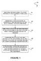
- FIG. 1illustrates a method for synchronizing data using data identifying messages in accordance with an embodiment
- FIG. 2illustrates a system for synchronizing data in a forecasting environment using data identifying messages in accordance with an embodiment
- FIGS. 3A-3Billustrate a method for conditionally synchronizing source and target data using a single identifier of the data in accordance with an embodiment
- FIG. 4illustrates a block diagram of an example of an environment wherein an on-demand database service might be used.
- FIG. 5illustrates a block diagram of an embodiment of elements of FIG. 4 and various possible interconnections between these elements.
- multi-tenant database systemrefers to those systems in which various elements of hardware and software of the database system may be shared by one or more customers. For example, a given application server may simultaneously process requests for a great number of customers, and a given database table may store rows for a potentially much greater number of customers.
- query planrefers to a set of steps used to access information in a database system.
- FIG. 1illustrates a method 100 for synchronizing data using data identifying messages in accordance with an embodiment.
- an update made to a first instance of data stored in a first data setis identified.
- the first data setincludes any data set that is separate from a second set data, such that the first instance of the data stored in the first data set is separate from a second instance of the data stored in the second data set, as described in more detail below.
- separationmay be a physical separation (e.g. by the data sets being stored on different servers, etc.) or a logical separation (e.g. by the data sets being stored in separate portions of the same memory).
- the first data setmay be source data, such that the first instance of the data is a portion of the source data.
- source datamay be accessible to a user for making the update to the first instance of the data.
- the updatemay be manually made to the first instance of the data, in one embodiment, by the user accessing the first instance of the data.
- the updatemay be automatically made to the first instance of the data, for example, by an application, code, etc. being executed to make the update to the first instance of the data.
- the second data set mentioned abovemay be target data, such that the second instance of the data is a portion of the target data.
- target datamay not necessarily be accessible to a user/application for updating the same, with the exception of updates made to the target data in accordance with the synchronization described with respect to the present method 100 .
- the second data setmay replicate the first data set by synchronizing the second data set with the first data set in the manner described below.
- the second data setmay store a processed version of the first data set.
- the processingmay include changing a granularity of the first data set.
- the first data setmay store the data in terms of that are more granular or less granular than the terms by which the data is stored in the second data set.
- the processingmay include normalizing a plurality of different types of data included in the first data set into a common format. In this way, the second data set may store all data in the common format.
- the processingmay include removing a portion of the first data set. Accordingly, the second data set may not necessarily be an exact copy of the first data set, but may be representation of the first data set that is formed in accordance with predefined configurations.
- the second data setmay be utilized for any desired purpose.
- the second data setmay be utilized for generating reports, such as forecasts. Accordingly, the aforementioned processing of the data prior to storing the same in the second data set may be performed to allow for more efficient generation of reports using the second data set.
- the second data setmay store the data with a granularity that is utilized by a report generator, such that generation of a report does not necessarily require on-the-fly processing of the data to ensure that it is of the granularity required by the report.
- the second data setmay store the data in a common format, regardless of a type of the data, such that generation of a report does not necessarily require on-the-fly processing of the data to ensure that it is of the format required by the report. More information regarding the exemplary embodiment where the second data set is utilized for generating forecasts is described in U.S. Patent Publication No. 2011/0231848, entitled “FORECASTING SYSTEMS AND METHODS,” by Long et al., filed Mar. 16, 2011, the entire contents of which are incorporated herein by reference.
- both a first instance of the data and a second instance of the dataare stored in separate data sets.
- a message having an identifier of the first instance of the data to which the update was madeis generated. Such message may optionally be automatically generated in response to the update being made to the first instance of the data.
- the messagemay include only the identifier of the first instance of the data to which the update was made.
- identifiermay uniquely identify at least the first instance of the data.
- the identifiermay uniquely identify the data, including the first instance of the data and the second instance of the data.
- the identifiermay be stored (e.g. as a key, etc.) in association with the first instance of the data and optionally the second instance of the data.
- the identifiermay be automatically generated and stored in association with the first instance of the data upon a first creation, saving, etc. of the first instance of the data.
- the identifiermay be included in a record storing the first instance of the data.
- the identifiermay be determined from the first instance of the data that has been updated.
- the messagemay be of any desired format capable of communicating the identifier of the first instance of the data to which the update was made.
- the message formatmay be predetermined for use with an application utilized for synchronizing the second data set with the first data set.
- the format of the messagemay be such that the application is capable of parsing, reading, etc. the identifier of the first instance of the data included therein, the reasons for which are set forth below in more detail.
- the messageupon generation of the message, may be stored in a message queue.
- the message queuemay store all messages generated in response to an update to the first data set. Synchronization between the first data set and the second data set may then only be initiated upon retrieval of the message from the message queue. In this way, there may optionally be delay between the update made to the first instance of the data stored in the first data set and a processing of the message for conditionally initiating the synchronization of the second data set with the first data set.
- the messagemay be communicated directly to the application for use in conditionally initiating the synchronization of the second data set with the first data set.
- a state of the first instance of the data stored in the first data setis identified using the identifier included in the message.
- the state of the first instance of the datamay be identified in response to retrieving the message from the message queue.
- the identifier of the first instance of the datamay be retrieved from the message (e.g. obtained from the message queue) for use in identifying the state of the first instance of the data stored in the first data set.
- Such messagemay be parsed, or processed in any other manner for retrieving the identifier of the first instance of the data included therein.
- the identifier included in the messagemay be used to identify the state of the first instance of the data by locating the first instance of the data within the first data set using the identifier included in the message. The state of the located first instance of the data may then be identified. The first instance of the data may be located within the first data set by querying the first data set using the identifier included in the message, just by way of example.
- the state of the first instance of the datamay be any status, version, etc. of the first instance of the data stored in the first data set.
- the state of the first instance of the datamay be data values included in the first instance of the data. It should be noted that since the state of the first instance of the data is identified after the update has been made to the first instance of the data, and is specifically identified using the identifier of the first instance of the data included in the message generated in response to the update made to the first instance of the data, the identified state of the first instance of the data may reflect the update made to the first instance of the data.
- the identified state of the first instance of the datamay be a current state of the first instance of the data stored in the first data set. For example, if any other updates are made to the first instance of the data during the time period between the generation of the message and the identification of the state of the first instance of the data, the identified state of the first instance of the data may reflect those other updates.
- the state of the first instance of the data stored in the first data setis compared to a state of the second instance of the data stored in the second data set, as shown in operation 108 .
- the state of a second instance of the data stored in the second data setmay be any status, version, etc. of the second instance of the data stored in the second data set.
- the state of the second instance of the datamay be data values included in the second instance of the data.
- the state of the second instance of the data stored in the second data setmay be identified using the identifier included in the message.
- the second instance of the datamay optionally be stored in the second data set in association with the same identifier stored in the first data set in association with the first instance of the data.
- the identifier included in the messagemay be used to identify the state of the second instance of the data by locating the second instance of the data within the second data set using the identifier included in the message and identifying the state of the located second instance of the data.
- the state of the second instance of the data stored in the second data setmay be identified in any manner that is associated with the identification of the state of the first instance of the data in the first data set.
- the identified state of the second instance of the datamay not necessarily reflect the update made to the first instance of the data.
- the second instance of the datamay not have been synchronized with the first instance of the data to allow the second instance of the data to reflect the update made to the first instance of the data.
- the identified state of the second instance of the datamay be a current state of the second instance of the data stored in the second data set.
- the state of the second instance of the data that is identifiedmay reflect any previous synchronizations performed between the second instance of the data and the first instance of the data. This may even include the state of the second instance of the data already reflecting the update made to the first instance of the data in operation 102 , such as for example when a previous synchronization between the first instance of the data already having the update and the second instance of the data is performed per a message previously generated in response to a previous update to the first instance of the data.
- the second instance of the data stored in the second data set and the first instance of the data stored in the first data setare synchronized, based on the comparison.
- synchronizing the second instance of the data stored in the second data set and the first instance of the data stored in the first data setmay be include updating the second instance of the data stored in the second data set to replicate the first instance of the data stored in the first data set.
- update to the second instance of the datamay be processed, as described above, such that the updated second instance of the data is in a preconfigured format (e.g. granularity, etc.).
- the second instance of the data stored in the second data setmay be synchronized with the first instance of the data stored in the first data set in response to a result of the comparison indicating that the first instance of the data is different than the second instance of the data.
- the second instance of the data stored in the second data setmay be prevented from being synchronized with the first instance of the data stored in the first data set in response to a result of the comparison indicating that the first instance of the data is the same as the second instance of the data.
- a notification of a possible need to synchronize the second instance of the data with changes made to the first instance of the datamay be provided, without necessarily communicating the actual changes that are potentially to be made to the second instance of the data.
- Thismay allow more efficient data synchronization (e.g. with one message per update to the first instance of the data, etc.) while ensuring that synchronizations are conditionally performed based on up-to-date information (e.g. current states of the first instance of the data and the second instance of the data).
- FIG. 2illustrates a system 200 for synchronizing data in a forecasting environment using data identifying messages in accordance with an embodiment.
- the present system 200may be implemented to carry out the method 100 of FIG. 1 .
- the system 200may be implemented in any desired environment. It should also be noted that the aforementioned definitions may apply during the present description.
- the system 200stores both source data 202 and target data 206 , where the target data 206 replicates the source data 202 for use in generating a forecast.
- the system 200may be any computer system capable of storing and synchronizing the source data 202 and the target data 206 , for use in generating forecasts.
- the system 200may be a multi-tenant on-demand database system storing the source data 202 and the target data 206 for tenants of the system 200 . It should be noted that while forecasts are described with respect to the present system 200 , the system 200 may store the source data 202 and the target data 206 for any desired purpose (e.g. reporting, etc.).
- a first instance of data included in the source data 202is updated (e.g. by a user).
- the first instance of the datamay be stored in a record included in the source data 202 , for example.
- the first instance of the dataincludes an identifier of the first instance of the data (SOURCE_ 01 ), an identifier of an owner (OWNER) of the first instance of the data (e.g. a tenant on behalf of which the first instance of the data is stored), a date (DATE) associated with the first instance of the data, an identifier of a category (CATEGORY) of the first instance of the data, and the actual data (DATA) comprising the first instance of the data.
- a messageis generated that includes the identifier of the first instance of the data (SOURCE_ 01 ).
- the generated messageis communicated to and stored in a message queue 204 . Subsequently, the message is retrieved from the message queue 204 . The retrieval may occur in accordance with a periodic process, available processing resources, etc.
- a second instance of the data stored in the target data 206is conditionally synchronized with the first instance of the data stored in the source data 202 .
- the second instance of the datamay be stored in a record included in the target data 206 , for example.
- the second instance of the datamay be a processed version of the first instance of the data, as an option.
- the second instance of the datamay only be a reflection of a state of the first instance of the data, in accordance with a preconfigured format.
- the second instance of the dataincludes the identifier of the first instance of the data (SOURCE_ 01 ), a key (KEY) to an aggregate (or other report, etc.) that has been formed based on the second instance of the data, a an identifier of a category (CATEGORY) of the second instance of the data, and the actual data (DATA) comprising the second instance of the data.
- the identifier (SOURCE_ 01 ) included in the messageis retrieved from the message and used to locate the first instance of the data with which the identifier is associated in the source data 202 . A state of the located first instance of the data is then identified. Additionally, the identifier (SOURCE_ 01 ) retrieved from the message is used to locate the second instance of the data with which the identifier is associated in the target data 206 , such that a state of the located second instance of the data is then identified. The state of the first instance of the data is compared with the state of the second instance of the data, and the second instance of the data is conditionally synchronized based on the comparison. For example, if it is determined that the first instance of the data and the second instance of the data match, the synchronization of the second instance of the data with the first instance of the data is avoided.
- the second instance of the datais synchronized with the first instance of the data.
- the second instance of the datamay be updated to reflect the update made to the first instance of the data.
- the synchronizationmay include processing the state of the first instance of the data and storing a result of the processing as the second instance of the data.
- the second instance of the datamay reflect the current state of the first instance of the data, in accordance with a preconfigured format.
- the system 208relates to a forecasting system in which a forecasting item 208 is stored having the key (KEY) to the second instance of the data and stores an identifier of a category (CATEGORY).
- the forecasting item 208represents an aggregate of the target data 206 that is generated in accordance with a forecasting key 210 stored by the system 200 .
- the forecasting key 210includes the key (KEY), owner (OWNER), and time period (PERIOD) forming the basis for the aggregation represented by the forecasting item 208 .
- the aggregatemay combine portions of the target data 206 based on the time period (PERIOD), such that the portions of the target data 206 included in the aggregate defined may only be associated with a date (DATE) included in the specified period (PERIOD).
- the aggregatemay be updated to reflect the new data value.
- the aggregatemay be updated to either (1) include the data value in the aggregate when the new date falls within the time period (PERIOD) specific to the aggregate, or (2) remove the data value from the aggregate when the new date falls outside of the time period (PERIOD) specific to the aggregate.
- PERIODtime period
- Various examples of updating forecasts (e.g. aggregates) in response to an update to target data 206is described in U.S. Patent Publication No. 2011/0231848, entitled “FORECASTING SYSTEMS AND METHODS.” by Long et al., filed Mar. 16, 2011, the entire contents of which are incorporated herein by reference.
- a usermay update the first instance of the data stored in the source data 202 to specifically update a data value (DATA) of the first instance of the data from $1,000 to $1,500.
- the second instance of the data stored in the target data 206may include the original $1.000 data value, per a previous synchronization of the second instance of the data with the first instance of the data prior to the update being made to the first instance of the data.
- a messageis generated in response to the update, where the message is generated to include the identifier of the first instance of the data.
- the messageis then stored in the message queue 204 .
- the messageis retrieved from the message queue 204 , and the identifier therein is used to identify (i.e. read) a state of the first instance of the data and a state of the second instance of the data.
- locksmay be used to avoid race conditions.
- the locksmay be used since it is unknown which data is to be locked at the time the message is being retrieved from the message queue 204 .
- the first instance of the data stored in the source data 202may be read tentatively (e.g. unsafely) to identify the state thereof, then the state of the second instance of the data may be determined and compared to the state of the first instance of the data. If the states do not match, the forecasting item 208 and the second instance of the data stored in the target data 206 are locked, and once those locks are in place the first instance of the data stored in the source data 202 is again read (e.g. safely) to determine whether the states still do not match.
- the second instance of the datais updated accordingly to reflect the first instance of the data, and furthermore, the forecasting item 208 is updated to reflect the change made to the target data 206 .
- the locksare removed.
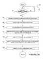
- FIGS. 3A-3Billustrate a method 300 for conditionally synchronizing source and target data using a single identifier of the data in accordance with an embodiment.
- the method 300may be carried out in the context of FIGS. 1-2 .
- the method 300may be carried out in any desired environment. It should also be noted that the aforementioned definitions may apply during the present description.
- decision 302it is determined whether a change to source data has been made. If it is determined that a change to source data has not been made, the method 300 continues to wait for such a change to be made. Once it is determined that a change to source data has been made, a message having an identifier of the source data is generated. Note operation 304 .
- the messageis enqueued in a message queue, as shown in operation 306 .
- the messageis dequeued from the message queue (operation 308 ), and the source data is identified using the identifier of the source data included in the message (operation 310 ).
- a state of the source datais identified, in response to the identification of the source data.
- Corresponding target datais then identified using the identifier of the source data included in the message (operation 314 ), and a state of the target data is then identified (operation 316 ).
- the state of the source data and the state of the target dataare compared, as shown in operation 318 . Based on the comparison, it is determined whether the source data and the target data match, as shown in decision 320 . If it is determined that the source data and the target data match, the method 300 terminates. If, however, it is determined that the source data and the target data do not match, the target data is locked (operation 322 ) and synchronized with the source data (operation 324 ). Once the synchronization is complete, the target data is unlocked, as shown in operation 326 , and the method 300 terminates.
- FIG. 4illustrates a block diagram of an environment 410 wherein an on-demand database service might be used.
- Environment 410may include user systems 412 , network 414 , system 416 , processor system 417 , application platform 418 , network interface 420 , tenant data storage 422 , system data storage 424 , program code 426 , and process space 428 .
- environment 410may not have all of the components listed and/or may have other elements instead of, or in addition to, those listed above.
- Environment 410is an environment in which an on-demand database service exists.
- User system 412may be any machine or system that is used by a user to access a database user system.
- any of user systems 412can be a handheld computing device, a mobile phone, a laptop computer, a work station, and/or a network of computing devices.
- user systems 412might interact via a network 414 with an on-demand database service, which is system 416 .
- An on-demand database servicesuch as system 416
- system 416is a database system that is made available to outside users that do not need to necessarily be concerned with building and/or maintaining the database system, but instead may be available for their use when the users need the database system (e.g., on the demand of the users).
- Some on-demand database servicesmay store information from one or more tenants stored into tables of a common database image to form a multi-tenant database system (MTS).
- MTSmulti-tenant database system
- “on-demand database service 416 ” and “system 416 ”will be used interchangeably herein.
- a database imagemay include one or more database objects.
- Application platform 418may be a framework that allows the applications of system 416 to run, such as the hardware and/or software, e.g., the operating system.
- on-demand database service 416may include an application platform 418 that enables creation, managing and executing one or more applications developed by the provider of the on-demand database service, users accessing the on-demand database service via user systems 412 , or third party application developers accessing the on-demand database service via user systems 412 .
- the users of user systems 412may differ in their respective capacities, and the capacity of a particular user system 412 might be entirely determined by permissions (permission levels) for the current user. For example, where a salesperson is using a particular user system 412 to interact with system 416 , that user system has the capacities allotted to that salesperson. However, while an administrator is using that user system to interact with system 416 , that user system has the capacities allotted to that administrator.
- users at one permission levelmay have access to applications, data, and database information accessible by a lower permission level user, but may not have access to certain applications, database information, and data accessible by a user at a higher permission level. Thus, different users will have different capabilities with regard to accessing and modifying application and database information, depending on a user's security or permission level.
- Network 414is any network or combination of networks of devices that communicate with one another.
- network 414can be any one or any combination of a LAN (local area network), WAN (wide area network), telephone network, wireless network, point-to-point network, star network, token ring network, hub network, or other appropriate configuration.
- LANlocal area network
- WANwide area network
- telephone networkwireless network
- point-to-point networkstar network
- token ring networktoken ring network
- hub networkor other appropriate configuration.
- TCP/IPTransfer Control Protocol and Internet Protocol
- User systems 412might communicate with system 416 using TCP/IP and, at a higher network level, use other common Internet protocols to communicate, such as HTTP, FTP, AFS, WAP, etc.
- HTTPHyperText Transfer Protocol
- user system 412might include an HTTP client commonly referred to as a “browser” for sending and receiving HTTP messages to and from an HTTP server at system 416 .
- HTTP servermight be implemented as the sole network interface between system 416 and network 414 , but other techniques might be used as well or instead.
- the interface between system 416 and network 414includes load sharing functionality, such as round-robin HTTP request distributors to balance loads and distribute incoming HTTP requests evenly over a plurality of servers. At least as for the users that are accessing that server, each of the plurality of servers has access to the MTS' data; however, other alternative configurations may be used instead.
- system 416implements a web-based customer relationship management (CRM) system.
- system 416includes application servers configured to implement and execute CRM software applications as well as provide related data, code, forms, webpages and other information to and from user systems 412 and to store to, and retrieve from, a database system related data, objects, and Webpage content.
- CRMcustomer relationship management
- data for multiple tenantsmay be stored in the same physical database object, however, tenant data typically is arranged so that data of one tenant is kept logically separate from that of other tenants so that one tenant does not have access to another tenant's data, unless such data is expressly shared.
- system 416implements applications other than, or in addition to, a CRM application.
- system 416may provide tenant access to multiple hosted (standard and custom) applications, including a CRM application.
- User (or third party developer) applicationswhich may or may not include CRM, may be supported by the application platform 418 , which manages creation, storage of the applications into one or more database objects and executing of the applications in a virtual machine in the process space of the system 416 .
- FIG. 4One arrangement for elements of system 416 is shown in FIG. 4 , including a network interface 420 , application platform 418 , tenant data storage 422 for tenant data 423 , system data storage 424 for system data 425 accessible to system 416 and possibly multiple tenants, program code 426 for implementing various functions of system 416 , and a process space 428 for executing MTS system processes and tenant-specific processes, such as running applications as part of an application hosting service. Additional processes that may execute on system 416 include database indexing processes.
- each user system 412could include a desktop personal computer, workstation, laptop, PDA, cell phone, or any wireless access protocol (WAP) enabled device or any other computing device capable of interfacing directly or indirectly to the Internet or other network connection.
- WAPwireless access protocol
- User system 412typically runs an HTTP client, e.g., a browsing program, such as Microsoft's Internet Explorer browser, Netscape's Navigator browser, Opera's browser, or a WAP-enabled browser in the case of a cell phone, PDA or other wireless device, or the like, allowing a user (e.g., subscriber of the multi-tenant database system) of user system 412 to access, process and view information, pages and applications available to it from system 416 over network 414 .
- HTTP cliente.g., a browsing program, such as Microsoft's Internet Explorer browser, Netscape's Navigator browser, Opera's browser, or a WAP-enabled browser in the case of a cell phone, PDA or other wireless device, or the like.
- Each user system 412also typically includes one or more user interface devices, such as a keyboard, a mouse, trackball, touch pad, touch screen, pen or the like, for interacting with a graphical user interface (GUI) provided by the browser on a display a monitor screen, LCD display, etc.) in conjunction with pages, forms, applications and other information provided by system 416 or other systems or servers.
- GUIgraphical user interface
- the user interface devicecan be used to access data and applications hosted by system 416 , and to perform searches on stored data, and otherwise allow a user to interact with various GUI pages that may be presented to a user.
- embodimentsare suitable for use with the Internet, which refers to a specific global internetwork of networks. However, it should be understood that other networks can be used instead of the Internet, such as an intranet, an extranet, a virtual private network (VPN), a non-TCP/IP based network, any LAN or WAN or the like.
- VPNvirtual private network
- each user system 412 and all of its componentsare operator configurable using applications, such as a browser, including computer code run using a central processing unit such as an Intel Pentium® processor or the like.
- system 416 (and additional instances of an MTS, where more than one is present) and all of their componentsmight be operator configurable using application(s) including computer code to run using a central processing unit such as processor system 417 , which may include an Pentium® processor or the like, and/or multiple processor units.
- a computer program product embodimentincludes a machine-readable storage medium (media) having instructions stored thereon/in which can be used to program a computer to perform any of the processes of the embodiments described herein.
- Computer code for operating and configuring system 416 to intercommunicate and to process webpages, applications and other data and media content as described hereinare preferably downloaded and stored on a hard disk, but the entire program code, or portions thereof, may also be stored in any other volatile or non-volatile memory medium or device as is well known, such as a ROM or RAM, or provided on any media capable of storing program code, such as any type of rotating media including floppy disks, optical discs, digital versatile disk (DVD), compact disk (CD), microdrive, and magneto-optical disks, and magnetic or optical cards, nanosystems (including molecular memory ICs), or any type of media or device suitable for storing instructions and/or data.
- any type of rotating mediaincluding floppy disks, optical discs, digital versatile disk (DVD), compact disk (CD), microdrive, and magneto-optical disks, and magnetic or optical cards, nanosystems (including molecular memory ICs), or any type of media or device suitable for storing instructions and/or data.
- the entire program code, or portions thereofmay be transmitted and downloaded from a software source over a transmission medium, e.g., over the Internet, or from another server, as is well known, or transmitted over any other conventional network connection as is well known (e.g., extranet, VPN, LAN, etc.) using any communication medium and protocols (e.g., TCP/IP, HTTP, HTTPS, Ethernet, etc.) as are well known.
- a transmission mediume.g., over the Internet
- any other conventional network connectione.g., extranet, VPN, LAN, etc.
- any communication medium and protocolse.g., TCP/IP, HTTP, HTTPS, Ethernet, etc.
- computer code for implementing embodimentscan be implemented in any programming language that can be executed on a client system and/or server or server system such as, for example, C, C++, HTML, any other markup language, JavaTM, JavaScript, ActiveX, any other scripting language, such as VBScript, and many other programming languages as are well known may be used.
- JavaTMis a trademark of Sun Microsystems, Inc.
- each system 416is configured to provide webpages, forms, applications, data and media content to user (client) systems 412 to support the access by user systems 412 as tenants of system 416 .
- system 416provides security mechanisms to keep each tenant's data separate unless the data is shared.
- MTSMobility Management Entity
- theymay be located in close proximity to one another (e.g., in a server farm located in a single building or campus), or they may be distributed at locations remote from one another (e.g., one or more servers located in city A and one or more servers located in city B).
- each MTScould include one or more logically and/or physically connected servers distributed locally or across one or more geographic locations.
- serveris meant to include a computer system, including processing hardware and process space(s), and an associated storage system and database application (e.g., OODBMS or RDBMS) as is well known in the art. It should also be understood that “server system” and “server” are often used interchangeably herein.
- database object described hereincan be implemented as single databases, a distributed database, a collection of distributed databases, a database with redundant online or offline backups or other redundancies, etc., and might include a distributed database or storage network and associated processing intelligence.
- FIG. 5also illustrates environment 410 . However, in FIG. 5 elements of system 416 and various interconnections in an embodiment are further illustrated.
- user system 412may include processor system 412 A, memory system 412 B, input system 412 C, and output system 412 D.
- FIG. 5shows network 414 and system 416 .
- system 416may include tenant data storage 422 , tenant data 423 , system data storage 424 , system data 425 , User Interface (UI) 530 , Application Program Interface (API) 532 , PL/SOQL 534 , save routines 536 , application setup mechanism 538 , applications servers 500 1 - 500 N , system process space 502 , tenant process spaces 504 , tenant management process space 510 , tenant storage area 512 , user storage 514 , and application metadata 516 .
- environment 410may not have the same elements as those listed above and/or may have other elements instead of, or in addition to, those listed above.
- processor system 412 Amay be any combination of one or more processors.
- Memory system 412 Bmay be any combination of one or more memory devices, short term, and/or long term memory.
- Input system 412 Cmay be any combination of input devices, such as one or more keyboards, mice, trackballs, scanners, cameras, and/or interfaces to networks.
- Output system 412 Dmay be any combination of output devices, such as one or more monitors, printers, and/or interfaces to networks.
- system 416may include a network interface 420 (of FIG.
- Each application server 500may be configured to tenant data storage 422 and the tenant data 423 therein, and system data storage 424 and the system data 425 therein to serve requests of user systems 412 .
- the tenant data 423might be divided into individual tenant storage areas 512 , which can be either a physical arrangement and/or a logical arrangement of data.
- user storage 514 and application metadata 516might be similarly allocated for each user.
- a UI 530provides a user interface and an API 532 provides an application programmer interface to system 416 resident processes to users and/or developers at user systems 412 .
- the tenant data and the system datamay be stored in various databases, such as one or more OracleTM databases.
- Application platform 418includes an application setup mechanism 538 that supports application developers' creation and management of applications, which may be saved as metadata into tenant data storage 422 by save routines 536 for execution by subscribers as one or more tenant process spaces 504 managed by tenant management process 510 for example. Invocations to such applications may be coded using PL/SOQL 534 that provides a programming language style interface extension to API 532 .
- PL/SOQL 534provides a programming language style interface extension to API 532 .
- a detailed description of some PL/SOQL language embodimentsis discussed in commonly owned U.S. Pat. No. 7,730,478, entitled “METHOD AND SYSTEM FOR ALLOWING ACCESS TO DEVELOPED APPLICATIONS VIA A MULTI-TENANT ON-DEMAND DATABASE SERVICE,” issued Jun.
- Invocations to applicationsmay be detected by one or more system processes, which manages retrieving application metadata 516 for the subscriber making the invocation and executing the metadata as an application in a virtual machine.
- Each application server 500may be communicably coupled to database systems, e.g., having access to system data 425 and tenant data 423 , via a different network connection.
- one application server 500 1might be coupled via the network 414 (e.g., the Internet)
- another application server 500 N-1might be coupled via a direct network link
- another application server 500 Nmight be coupled by yet a different, network connection.
- Transfer Control Protocol and Internet ProtocolTCP/IP
- TCP/IPTransfer Control Protocol and Internet Protocol
- each application server 500is configured to handle requests for any user associated with any organization that is a tenant. Because it is desirable to be able to add and remove application servers from the server pool at any time for any reason, there is preferably no server affinity for a user and/or organization to a specific application server 500 .
- an interface system implementing a load balancing functione.g., an F5 Big-IP load balancer
- the load balanceruses a least connections algorithm to route user requests to the application servers 500 .
- Other examples of load balancing algorithmssuch as round robin and observed response time, also can be used.
- system 416is multi-tenant, wherein system 416 handles storage of, and access to, different objects, data and applications across disparate users and organizations.
- one tenantmight be a company that employs a sales force where each salesperson uses system 416 to manage their sales process.
- a usermight maintain contact data, leads data, customer follow-up data, performance data, goals and progress data, etc., all applicable to that user's personal sales process (e.g., in tenant data storage 422 ).
- tenant data storage 422e.g., in tenant data storage 422 .
- the usercan manage his or her sales efforts and cycles from any of many different user systems. For example, if a salesperson is visiting a customer and the customer has Internet access in their lobby, the salesperson can obtain critical updates as to that customer while waiting for the customer to arrive in the lobby.
- user systems 412(which may be client systems) communicate with application servers 500 to request and update system-level and tenant-level data from system 416 that may require sending one or more queries to tenant data storage 422 and/or system data storage 424 .
- System 416e.g., an application server 500 in system 416
- System data storage 424may generate query plans to access the requested data from the database.
- Each databasecan generally be viewed as a collection of objects, such as a set of logical tables, containing data fitted into predefined categories.
- a “table”is one representation of a data object, and may be used herein to simplify the conceptual description of objects and custom objects. It should be understood that “table” and “object” may be used interchangeably herein.
- Each tablegenerally contains one or more data categories logically arranged as columns or fields in a viewable schema. Each row or record of a table contains an instance of data for each category defined by the fields.
- a CRM databasemay include a table that describes a customer with fields for basic contact information such as name, address, phone number, fax number, etc.
- Another tablemight describe a purchase order, including fields for information such as customer, product, sale price, date, etc.
- standard entity tablesmight be provided for use by all tenants.
- such standard entitiesmight include tables for Account, Contact, Lead, and Opportunity data, each containing pre-defined fields. It should be understood that the word “entity” may also be used interchangeably herein with “object” and “table”.
- tenantsmay be allowed to create and store custom objects, or they may be allowed to customize standard entities or objects, for example by creating custom fields for standard objects, including custom index fields.
- U.S. Pat. No. 7,779,039entitled “CUSTOM ENTITIES AND FIELDS IN A MULTI-TENANT DATABASE SYSTEM”, issued Aug. 27, 2010 to Craig Weissman, and hereby incorporated herein by reference, teaches systems and methods for creating custom objects as well as customizing standard objects in a multi-tenant database system.
- all custom entity data rowsare stored in a single multi-tenant physical table, which may contain multiple logical tables per organization. It is transparent to customers that their multiple “tables” are in fact stored in one large table or that their data may be stored in the same table as the data of other customers.
Landscapes
- Engineering & Computer Science (AREA)
- Databases & Information Systems (AREA)
- Theoretical Computer Science (AREA)
- Computing Systems (AREA)
- Data Mining & Analysis (AREA)
- Physics & Mathematics (AREA)
- General Engineering & Computer Science (AREA)
- General Physics & Mathematics (AREA)
- Information Retrieval, Db Structures And Fs Structures Therefor (AREA)
Abstract
Description
Claims (15)
Priority Applications (1)
| Application Number | Priority Date | Filing Date | Title |
|---|---|---|---|
| US13/653,337US8812438B2 (en) | 2012-01-20 | 2012-10-16 | System, method and computer program product for synchronizing data using data identifying messages |
Applications Claiming Priority (2)
| Application Number | Priority Date | Filing Date | Title |
|---|---|---|---|
| US201261589161P | 2012-01-20 | 2012-01-20 | |
| US13/653,337US8812438B2 (en) | 2012-01-20 | 2012-10-16 | System, method and computer program product for synchronizing data using data identifying messages |
Publications (2)
| Publication Number | Publication Date |
|---|---|
| US20130191333A1 US20130191333A1 (en) | 2013-07-25 |
| US8812438B2true US8812438B2 (en) | 2014-08-19 |
Family
ID=48798069
Family Applications (1)
| Application Number | Title | Priority Date | Filing Date |
|---|---|---|---|
| US13/653,337Active2032-11-02US8812438B2 (en) | 2012-01-20 | 2012-10-16 | System, method and computer program product for synchronizing data using data identifying messages |
Country Status (1)
| Country | Link |
|---|---|
| US (1) | US8812438B2 (en) |
Cited By (3)
| Publication number | Priority date | Publication date | Assignee | Title |
|---|---|---|---|---|
| US11372889B2 (en)* | 2015-04-22 | 2022-06-28 | The Bank Of New York Mellon | Multi-modal-based generation of data synchronization instructions |
| US11743329B1 (en)* | 2017-07-28 | 2023-08-29 | Zero Cognitive Systems, Inc. | Automatically synchronizing data across applications installed on multiple devices via mail server |
| US12326876B1 (en) | 2024-08-28 | 2025-06-10 | StoreConnect International Pty Ltd | Systems and methods for managing web, mobile, and point-of-sale servers with a customer relations management system |
Families Citing this family (3)
| Publication number | Priority date | Publication date | Assignee | Title |
|---|---|---|---|---|
| US8812438B2 (en)* | 2012-01-20 | 2014-08-19 | Salesforce.Com, Inc. | System, method and computer program product for synchronizing data using data identifying messages |
| US20160100004A1 (en) | 2014-10-06 | 2016-04-07 | International Business Machines Corporation | Data replication across servers |
| US12360827B1 (en)* | 2018-11-27 | 2025-07-15 | Marvell Israel (M.I.S.L) Ltd. | Event message buffer and method of effective guaranteed event message buffering |
Citations (134)
| Publication number | Priority date | Publication date | Assignee | Title |
|---|---|---|---|---|
| US5577188A (en) | 1994-05-31 | 1996-11-19 | Future Labs, Inc. | Method to provide for virtual screen overlay |
| US5608872A (en) | 1993-03-19 | 1997-03-04 | Ncr Corporation | System for allowing all remote computers to perform annotation on an image and replicating the annotated image on the respective displays of other comuters |
| US5649104A (en) | 1993-03-19 | 1997-07-15 | Ncr Corporation | System for allowing user of any computer to draw image over that generated by the host computer and replicating the drawn image to other computers |
| US5715450A (en) | 1995-09-27 | 1998-02-03 | Siebel Systems, Inc. | Method of selecting and presenting data from a database using a query language to a user of a computer system |
| US5821937A (en) | 1996-02-23 | 1998-10-13 | Netsuite Development, L.P. | Computer method for updating a network design |
| US5831610A (en) | 1996-02-23 | 1998-11-03 | Netsuite Development L.P. | Designing networks |
| US5873096A (en) | 1997-10-08 | 1999-02-16 | Siebel Systems, Inc. | Method of maintaining a network of partially replicated database system |
| US5918159A (en) | 1997-08-04 | 1999-06-29 | Fomukong; Mundi | Location reporting satellite paging system with optional blocking of location reporting |
| US5963953A (en) | 1998-03-30 | 1999-10-05 | Siebel Systems, Inc. | Method, and system for product configuration |
| US6092083A (en) | 1997-02-26 | 2000-07-18 | Siebel Systems, Inc. | Database management system which synchronizes an enterprise server and a workgroup user client using a docking agent |
| US6161149A (en) | 1998-03-13 | 2000-12-12 | Groupserve, Inc. | Centrifugal communication and collaboration method |
| US6169534B1 (en) | 1997-06-26 | 2001-01-02 | Upshot.Com | Graphical user interface for customer information management |
| US6178425B1 (en) | 1997-02-26 | 2001-01-23 | Siebel Systems, Inc. | Method of determining the visibility to a remote database client of a plurality of database transactions using simplified visibility rules |
| US6216135B1 (en) | 1997-02-26 | 2001-04-10 | Siebel Systems, Inc. | Method of determining visibility to a remote database client of a plurality of database transactions having variable visibility strengths |
| US6233617B1 (en) | 1997-02-26 | 2001-05-15 | Siebel Systems, Inc. | Determining the visibility to a remote database client |
| US6266669B1 (en) | 1997-02-28 | 2001-07-24 | Siebel Systems, Inc. | Partially replicated distributed database with multiple levels of remote clients |
| US6295530B1 (en) | 1995-05-15 | 2001-09-25 | Andrew M. Ritchie | Internet service of differently formatted viewable data signals including commands for browser execution |
| US20010044791A1 (en) | 2000-04-14 | 2001-11-22 | Richter James Neal | Automated adaptive classification system for bayesian knowledge networks |
| US6324693B1 (en) | 1997-03-12 | 2001-11-27 | Siebel Systems, Inc. | Method of synchronizing independently distributed software and database schema |
| US6324568B1 (en) | 1999-11-30 | 2001-11-27 | Siebel Systems, Inc. | Method and system for distributing objects over a network |
| US6336137B1 (en) | 2000-03-31 | 2002-01-01 | Siebel Systems, Inc. | Web client-server system and method for incompatible page markup and presentation languages |
| US20020022986A1 (en) | 1998-11-30 | 2002-02-21 | Coker John L. | Smart scripting call centers |
| USD454139S1 (en) | 2001-02-20 | 2002-03-05 | Rightnow Technologies | Display screen for a computer |
| US20020029376A1 (en) | 1998-11-30 | 2002-03-07 | Jesse Ambrose | Development tool, method, and system for client server applications |
| US20020029161A1 (en) | 1998-11-30 | 2002-03-07 | Brodersen Robert A. | Assignment manager |
| US6367077B1 (en) | 1997-02-27 | 2002-04-02 | Siebel Systems, Inc. | Method of upgrading a software application in the presence of user modifications |
| US20020042264A1 (en) | 2000-10-11 | 2002-04-11 | Lg Electronics Inc. | Data communication method using mobile terminal |
| US6393605B1 (en) | 1998-11-18 | 2002-05-21 | Siebel Systems, Inc. | Apparatus and system for efficient delivery and deployment of an application |
| US20020072951A1 (en) | 1999-03-03 | 2002-06-13 | Michael Lee | Marketing support database management method, system and program product |
| US20020082892A1 (en) | 1998-08-27 | 2002-06-27 | Keith Raffel | Method and apparatus for network-based sales force management |
| US6434550B1 (en) | 2000-04-14 | 2002-08-13 | Rightnow Technologies, Inc. | Temporal updates of relevancy rating of retrieved information in an information search system |
| US6446089B1 (en) | 1997-02-26 | 2002-09-03 | Siebel Systems, Inc. | Method of using a cache to determine the visibility to a remote database client of a plurality of database transactions |
| US20020143997A1 (en) | 2001-03-28 | 2002-10-03 | Xiaofei Huang | Method and system for direct server synchronization with a computing device |
| US20020140731A1 (en) | 2001-03-28 | 2002-10-03 | Pavitra Subramaniam | Engine to present a user interface based on a logical structure, such as one for a customer relationship management system, across a web site |
| US20020162090A1 (en) | 2001-04-30 | 2002-10-31 | Parnell Karen P. | Polylingual simultaneous shipping of software |
| US20020165742A1 (en) | 2000-03-31 | 2002-11-07 | Mark Robins | Feature centric release manager method and system |
| US20030004971A1 (en) | 2001-06-29 | 2003-01-02 | Gong Wen G. | Automatic generation of data models and accompanying user interfaces |
| US20030018705A1 (en) | 2001-03-31 | 2003-01-23 | Mingte Chen | Media-independent communication server |
| US20030018830A1 (en) | 2001-02-06 | 2003-01-23 | Mingte Chen | Adaptive communication application programming interface |
| US6535909B1 (en) | 1999-11-18 | 2003-03-18 | Contigo Software, Inc. | System and method for record and playback of collaborative Web browsing session |
| US20030066031A1 (en) | 2001-09-28 | 2003-04-03 | Siebel Systems, Inc. | Method and system for supporting user navigation in a browser environment |
| US20030066032A1 (en) | 2001-09-28 | 2003-04-03 | Siebel Systems,Inc. | System and method for facilitating user interaction in a browser environment |
| US20030070005A1 (en) | 2001-09-29 | 2003-04-10 | Anil Mukundan | Method, apparatus, and system for implementing view caching in a framework to support web-based applications |
| US20030070004A1 (en) | 2001-09-29 | 2003-04-10 | Anil Mukundan | Method, apparatus, and system for implementing a framework to support a web-based application |
| US20030070000A1 (en) | 2001-09-29 | 2003-04-10 | John Coker | Computing system and method to implicitly commit unsaved data for a World Wide Web application |
| US20030069936A1 (en) | 2001-10-09 | 2003-04-10 | Warner Douglas K. | Method for routing electronic correspondence based on the level and type of emotion contained therein |
| US20030074418A1 (en) | 2001-09-29 | 2003-04-17 | John Coker | Method, apparatus and system for a mobile web client |
| US6560461B1 (en) | 1997-08-04 | 2003-05-06 | Mundi Fomukong | Authorized location reporting paging system |
| US6574635B2 (en) | 1999-03-03 | 2003-06-03 | Siebel Systems, Inc. | Application instantiation based upon attributes and values stored in a meta data repository, including tiering of application layers objects and components |
| US6577726B1 (en) | 2000-03-31 | 2003-06-10 | Siebel Systems, Inc. | Computer telephony integration hotelling method and system |
| US6601087B1 (en) | 1998-11-18 | 2003-07-29 | Webex Communications, Inc. | Instant document sharing |
| US6604117B2 (en) | 1996-03-19 | 2003-08-05 | Siebel Systems, Inc. | Method of maintaining a network of partially replicated database system |
| US20030151633A1 (en) | 2002-02-13 | 2003-08-14 | David George | Method and system for enabling connectivity to a data system |
| US20030159136A1 (en) | 2001-09-28 | 2003-08-21 | Huang Xiao Fei | Method and system for server synchronization with a computing device |
| US6621834B1 (en) | 1999-11-05 | 2003-09-16 | Raindance Communications, Inc. | System and method for voice transmission over network protocols |
| US20030189600A1 (en) | 2002-03-29 | 2003-10-09 | Prasad Gune | Defining an approval process for requests for approval |
| US20030204427A1 (en) | 2002-03-29 | 2003-10-30 | Prasad Gune | User interface for processing requests for approval |
| US20030206192A1 (en) | 2001-03-31 | 2003-11-06 | Mingte Chen | Asynchronous message push to web browser |
| US6654032B1 (en) | 1999-12-23 | 2003-11-25 | Webex Communications, Inc. | Instant sharing of documents on a remote server |
| US20030225730A1 (en) | 2002-06-03 | 2003-12-04 | Rightnow Technologies, Inc. | System and method for generating a dynamic interface via a communications network |
| US6665655B1 (en) | 2000-04-14 | 2003-12-16 | Rightnow Technologies, Inc. | Implicit rating of retrieved information in an information search system |
| US6665648B2 (en) | 1998-11-30 | 2003-12-16 | Siebel Systems, Inc. | State models for monitoring process |
| US20040001092A1 (en) | 2002-06-27 | 2004-01-01 | Rothwein Thomas M. | Prototyping graphical user interfaces |
| US20040010489A1 (en) | 2002-07-12 | 2004-01-15 | Rightnow Technologies, Inc. | Method for providing search-specific web pages in a network computing environment |
| US20040015981A1 (en) | 2002-06-27 | 2004-01-22 | Coker John L. | Efficient high-interactivity user interface for client-server applications |
| US20040027388A1 (en) | 2002-06-27 | 2004-02-12 | Eric Berg | Method and apparatus to facilitate development of a customer-specific business process model |
| US6711565B1 (en) | 2001-06-18 | 2004-03-23 | Siebel Systems, Inc. | Method, apparatus, and system for previewing search results |
| US6724399B1 (en) | 2001-09-28 | 2004-04-20 | Siebel Systems, Inc. | Methods and apparatus for enabling keyboard accelerators in applications implemented via a browser |
| US6728702B1 (en) | 2001-06-18 | 2004-04-27 | Siebel Systems, Inc. | System and method to implement an integrated search center supporting a full-text search and query on a database |
| US6728960B1 (en) | 1998-11-18 | 2004-04-27 | Siebel Systems, Inc. | Techniques for managing multiple threads in a browser environment |
| US6732100B1 (en) | 2000-03-31 | 2004-05-04 | Siebel Systems, Inc. | Database access method and system for user role defined access |
| US6732111B2 (en) | 1998-03-03 | 2004-05-04 | Siebel Systems, Inc. | Method, apparatus, system, and program product for attaching files and other objects to a partially replicated database |
| US6732095B1 (en) | 2001-04-13 | 2004-05-04 | Siebel Systems, Inc. | Method and apparatus for mapping between XML and relational representations |
| US20040128001A1 (en) | 2002-08-28 | 2004-07-01 | Levin Issac Stephen | Method and apparatus for an integrated process modeller |
| US6763501B1 (en) | 2000-06-09 | 2004-07-13 | Webex Communications, Inc. | Remote document serving |
| US6763351B1 (en) | 2001-06-18 | 2004-07-13 | Siebel Systems, Inc. | Method, apparatus, and system for attaching search results |
| US6772229B1 (en) | 2000-11-13 | 2004-08-03 | Groupserve, Inc. | Centrifugal communication and collaboration method |
| US6782383B2 (en) | 2001-06-18 | 2004-08-24 | Siebel Systems, Inc. | System and method to implement a persistent and dismissible search center frame |
| US20040186860A1 (en) | 2003-03-21 | 2004-09-23 | Wen-Hsin Lee | Method and architecture for providing data-change alerts to external applications via a push service |
| US20040193510A1 (en) | 2003-03-25 | 2004-09-30 | Catahan Nardo B. | Modeling of order data |
| US20040199543A1 (en) | 2003-04-04 | 2004-10-07 | Braud Luke A. | Facilitating data manipulation in a browser-based user interface of an enterprise business application |
| US20040199489A1 (en) | 2003-03-24 | 2004-10-07 | Barnes-Leon Maria Theresa | Custom common object |
| US20040199536A1 (en) | 2003-03-24 | 2004-10-07 | Barnes Leon Maria Theresa | Product common object |
| US6804330B1 (en) | 2002-01-04 | 2004-10-12 | Siebel Systems, Inc. | Method and system for accessing CRM data via voice |
| US6826582B1 (en) | 2001-09-28 | 2004-11-30 | Emc Corporation | Method and system for using file systems for content management |
| US6829655B1 (en) | 2001-03-28 | 2004-12-07 | Siebel Systems, Inc. | Method and system for server synchronization with a computing device via a companion device |
| US20040249854A1 (en) | 2003-03-24 | 2004-12-09 | Barnes-Leon Maria Theresa | Common common object |
| US20040260534A1 (en) | 2003-06-19 | 2004-12-23 | Pak Wai H. | Intelligent data search |
| US20040260659A1 (en) | 2003-06-23 | 2004-12-23 | Len Chan | Function space reservation system |
| US20040268299A1 (en) | 2003-06-30 | 2004-12-30 | Shu Lei | Application user interface template with free-form layout |
| US6842748B1 (en) | 2000-04-14 | 2005-01-11 | Rightnow Technologies, Inc. | Usage based strength between related information in an information retrieval system |
| US20050050555A1 (en) | 2003-08-28 | 2005-03-03 | Exley Richard Mark | Universal application network architecture |
| US6952741B1 (en)* | 1999-06-30 | 2005-10-04 | Computer Sciences Corporation | System and method for synchronizing copies of data in a computer system |
| US20060021019A1 (en) | 2004-07-21 | 2006-01-26 | International Business Machines Corporation | Method and system for federated provisioning |
| US7062502B1 (en) | 2001-12-28 | 2006-06-13 | Kesler John N | Automated generation of dynamic data entry user interface for relational database management systems |
| US20070038642A1 (en)* | 2004-09-15 | 2007-02-15 | Scott Durgin | Method for providing extensible software components within a distributed synchronization system |
| US7181758B1 (en) | 1994-07-25 | 2007-02-20 | Data Innovation, L.L.C. | Information distribution and processing system |
| US20070088707A1 (en)* | 2004-09-15 | 2007-04-19 | Scott Durgin | Method for providing extensible software components within a distributed synchronization system |
| US20070169081A1 (en)* | 2005-12-06 | 2007-07-19 | Dell Products L.P. | Method of defining packaging applicability |
| US7302466B1 (en)* | 2001-11-02 | 2007-11-27 | Sprint Communications Company L.P. | Autonomous eclone |
| US20080010243A1 (en)* | 2006-06-02 | 2008-01-10 | Salesforce.Com, Inc. | Method and system for pushing data to a plurality of devices in an on-demand service environment |
| US7340411B2 (en) | 1998-02-26 | 2008-03-04 | Cook Rachael L | System and method for generating, capturing, and managing customer lead information over a computer network |
| US20080082586A1 (en)* | 2006-10-02 | 2008-04-03 | Salesforce.Com, Inc | Method and system for selecting amongst a plurality of processes to send a message |
| US7356482B2 (en) | 1998-12-18 | 2008-04-08 | Alternative Systems, Inc. | Integrated change management unit |
| US7412455B2 (en) | 2003-04-30 | 2008-08-12 | Dillon David M | Software framework that facilitates design and implementation of database applications |
| US20090063415A1 (en) | 2007-08-31 | 2009-03-05 | Business Objects, S.A. | Apparatus and method for dynamically selecting componentized executable instructions at run time |
| US20090064147A1 (en)* | 2007-08-30 | 2009-03-05 | International Business Machines Corporation | Transaction aggregation to increase transaction processing throughout |
| US7508789B2 (en) | 1994-04-07 | 2009-03-24 | Data Innovation Llc | Information distribution and processing system |
| US7620655B2 (en) | 2003-05-07 | 2009-11-17 | Enecto Ab | Method, device and computer program product for identifying visitors of websites |
| US20100063959A1 (en)* | 2008-09-11 | 2010-03-11 | salesforce.com, Inc., | Automating sharing data between users of a multi-tenant database service |
| US20100088316A1 (en)* | 2008-05-02 | 2010-04-08 | Salesforce.Com, Inc. | Method and system for managing recent data in a mobile device linked to an on-demand service |
| US7698160B2 (en) | 1999-05-07 | 2010-04-13 | Virtualagility, Inc | System for performing collaborative tasks |
| US20100095064A1 (en)* | 2008-10-14 | 2010-04-15 | Aviles Joaquin J | Pattern Matching Technique |
| US20100100526A1 (en)* | 2005-11-03 | 2010-04-22 | Kt Corporation | Business logic device and processing method |
| US7730478B2 (en) | 2006-10-04 | 2010-06-01 | Salesforce.Com, Inc. | Method and system for allowing access to developed applications via a multi-tenant on-demand database service |
| US7779039B2 (en) | 2004-04-02 | 2010-08-17 | Salesforce.Com, Inc. | Custom entities and fields in a multi-tenant database system |
| US7783610B2 (en)* | 2004-11-01 | 2010-08-24 | Sybase, Inc. | Distributed database system providing data and space management methodology |
| US7788399B2 (en)* | 2001-03-26 | 2010-08-31 | Salesforce.Com, Inc. | System and method for mapping of services |
| US20100235322A1 (en)* | 2009-01-23 | 2010-09-16 | Salesforce.Com, Inc. | Methods and Systems for Sharing Information in a Supply Chain |
| US20100306536A1 (en)* | 2001-03-26 | 2010-12-02 | Salesforce.Com, Inc. | System and method for routing messages between applications |
| US20110231848A1 (en) | 2010-03-16 | 2011-09-22 | Salesforce.Com, Inc. | Forecasting systems and methods |
| US20110246503A1 (en)* | 2010-04-06 | 2011-10-06 | Bender Michael A | High-Performance Streaming Dictionary |
| US8082301B2 (en) | 2006-11-10 | 2011-12-20 | Virtual Agility, Inc. | System for supporting collaborative activity |
| US8095413B1 (en) | 1999-05-07 | 2012-01-10 | VirtualAgility, Inc. | Processing management information |
| US20120089783A1 (en)* | 2010-10-06 | 2012-04-12 | Red Hat Israel, Ltd. | Opcode length caching |
| US20120150829A1 (en)* | 2010-12-10 | 2012-06-14 | International Business Machines Corporation | Asynchronous Deletion of a Range of Messages Processed by a Parallel Database Replication Apply Process |
| US20120214521A1 (en)* | 2004-02-13 | 2012-08-23 | Envisionit, Llc | System and method for verifying message delivery integrity in a wireless mobile message broadcasting system |
| US8375081B2 (en)* | 2009-12-28 | 2013-02-12 | Microsoft Corporation | Calendar repair assistant |
| US20130041888A1 (en)* | 2005-12-01 | 2013-02-14 | Firestar Software, Inc. | System and method for exchanging information among exchange applications |
| US20130055263A1 (en)* | 2008-12-30 | 2013-02-28 | Steven King | Message communication techniques |
| US20130066832A1 (en)* | 2011-09-12 | 2013-03-14 | Microsoft Corporation | Application state synchronization |
| US8406633B1 (en)* | 2006-11-10 | 2013-03-26 | Marvell International Ltd. | Method and apparatus for data frame synchronization and delineation |
| US20130191333A1 (en)* | 2012-01-20 | 2013-07-25 | Salesforce.Com, Inc | System, method and computer program product for synchronizing data using data identifying messages |
| US20130346364A1 (en)* | 2009-09-16 | 2013-12-26 | Madhu Ahluwalia | Method and system for capturing change of data |
- 2012
- 2012-10-16USUS13/653,337patent/US8812438B2/enactiveActive
Patent Citations (163)
| Publication number | Priority date | Publication date | Assignee | Title |
|---|---|---|---|---|
| US5608872A (en) | 1993-03-19 | 1997-03-04 | Ncr Corporation | System for allowing all remote computers to perform annotation on an image and replicating the annotated image on the respective displays of other comuters |
| US5649104A (en) | 1993-03-19 | 1997-07-15 | Ncr Corporation | System for allowing user of any computer to draw image over that generated by the host computer and replicating the drawn image to other computers |
| US5761419A (en) | 1993-03-19 | 1998-06-02 | Ncr Corporation | Remote collaboration system including first program means translating user inputs into annotations and running on all computers while second program means runs on one computer |
| US5819038A (en) | 1993-03-19 | 1998-10-06 | Ncr Corporation | Collaboration system for producing copies of image generated by first program on first computer on other computers and annotating the image by second program |
| US7508789B2 (en) | 1994-04-07 | 2009-03-24 | Data Innovation Llc | Information distribution and processing system |
| US8457545B2 (en) | 1994-04-07 | 2013-06-04 | Online News Link Llc | Information distribution and processing system |
| US5577188A (en) | 1994-05-31 | 1996-11-19 | Future Labs, Inc. | Method to provide for virtual screen overlay |
| US7181758B1 (en) | 1994-07-25 | 2007-02-20 | Data Innovation, L.L.C. | Information distribution and processing system |
| US6295530B1 (en) | 1995-05-15 | 2001-09-25 | Andrew M. Ritchie | Internet service of differently formatted viewable data signals including commands for browser execution |
| US6826565B2 (en) | 1995-05-15 | 2004-11-30 | Ablaise Limited | Method and apparatus for serving files to browsing clients |
| US5715450A (en) | 1995-09-27 | 1998-02-03 | Siebel Systems, Inc. | Method of selecting and presenting data from a database using a query language to a user of a computer system |
| US5831610A (en) | 1996-02-23 | 1998-11-03 | Netsuite Development L.P. | Designing networks |
| US5821937A (en) | 1996-02-23 | 1998-10-13 | Netsuite Development, L.P. | Computer method for updating a network design |
| US6604117B2 (en) | 1996-03-19 | 2003-08-05 | Siebel Systems, Inc. | Method of maintaining a network of partially replicated database system |
| US6189011B1 (en) | 1996-03-19 | 2001-02-13 | Siebel Systems, Inc. | Method of maintaining a network of partially replicated database system |
| US6178425B1 (en) | 1997-02-26 | 2001-01-23 | Siebel Systems, Inc. | Method of determining the visibility to a remote database client of a plurality of database transactions using simplified visibility rules |
| US6092083A (en) | 1997-02-26 | 2000-07-18 | Siebel Systems, Inc. | Database management system which synchronizes an enterprise server and a workgroup user client using a docking agent |
| US6233617B1 (en) | 1997-02-26 | 2001-05-15 | Siebel Systems, Inc. | Determining the visibility to a remote database client |
| US6446089B1 (en) | 1997-02-26 | 2002-09-03 | Siebel Systems, Inc. | Method of using a cache to determine the visibility to a remote database client of a plurality of database transactions |
| US6216135B1 (en) | 1997-02-26 | 2001-04-10 | Siebel Systems, Inc. | Method of determining visibility to a remote database client of a plurality of database transactions having variable visibility strengths |
| US6684438B2 (en) | 1997-02-26 | 2004-02-03 | Siebel Systems, Inc. | Method of using cache to determine the visibility to a remote database client of a plurality of database transactions |
| US6367077B1 (en) | 1997-02-27 | 2002-04-02 | Siebel Systems, Inc. | Method of upgrading a software application in the presence of user modifications |
| US20020129352A1 (en) | 1997-02-27 | 2002-09-12 | Brodersen Robert A. | Method and apparatus for upgrading a software application in the presence of user modifications |
| US6754681B2 (en) | 1997-02-28 | 2004-06-22 | Siebel Systems, Inc. | Partially replicated distributed database with multiple levels of remote clients |
| US6405220B1 (en) | 1997-02-28 | 2002-06-11 | Siebel Systems, Inc. | Partially replicated distributed database with multiple levels of remote clients |
| US6266669B1 (en) | 1997-02-28 | 2001-07-24 | Siebel Systems, Inc. | Partially replicated distributed database with multiple levels of remote clients |
| US20020035577A1 (en) | 1997-02-28 | 2002-03-21 | Brodersen Robert A. | Partially replicated distributed database with multiple levels of remote clients |
| US6324693B1 (en) | 1997-03-12 | 2001-11-27 | Siebel Systems, Inc. | Method of synchronizing independently distributed software and database schema |
| US6169534B1 (en) | 1997-06-26 | 2001-01-02 | Upshot.Com | Graphical user interface for customer information management |
| US5918159A (en) | 1997-08-04 | 1999-06-29 | Fomukong; Mundi | Location reporting satellite paging system with optional blocking of location reporting |
| US6560461B1 (en) | 1997-08-04 | 2003-05-06 | Mundi Fomukong | Authorized location reporting paging system |
| US5873096A (en) | 1997-10-08 | 1999-02-16 | Siebel Systems, Inc. | Method of maintaining a network of partially replicated database system |
| US7340411B2 (en) | 1998-02-26 | 2008-03-04 | Cook Rachael L | System and method for generating, capturing, and managing customer lead information over a computer network |
| US6732111B2 (en) | 1998-03-03 | 2004-05-04 | Siebel Systems, Inc. | Method, apparatus, system, and program product for attaching files and other objects to a partially replicated database |
| US8015495B2 (en) | 1998-03-13 | 2011-09-06 | Groupserve It Trust Llc | Centrifugal communication and collaboration method |
| US6161149A (en) | 1998-03-13 | 2000-12-12 | Groupserve, Inc. | Centrifugal communication and collaboration method |
| US5963953A (en) | 1998-03-30 | 1999-10-05 | Siebel Systems, Inc. | Method, and system for product configuration |
| US20020082892A1 (en) | 1998-08-27 | 2002-06-27 | Keith Raffel | Method and apparatus for network-based sales force management |
| US6728960B1 (en) | 1998-11-18 | 2004-04-27 | Siebel Systems, Inc. | Techniques for managing multiple threads in a browser environment |
| US6393605B1 (en) | 1998-11-18 | 2002-05-21 | Siebel Systems, Inc. | Apparatus and system for efficient delivery and deployment of an application |
| US6549908B1 (en) | 1998-11-18 | 2003-04-15 | Siebel Systems, Inc. | Methods and apparatus for interpreting user selections in the context of a relation distributed as a set of orthogonalized sub-relations |
| US6601087B1 (en) | 1998-11-18 | 2003-07-29 | Webex Communications, Inc. | Instant document sharing |
| US6850895B2 (en) | 1998-11-30 | 2005-02-01 | Siebel Systems, Inc. | Assignment manager |
| US6826745B2 (en) | 1998-11-30 | 2004-11-30 | Siebel Systems, Inc. | System and method for smart scripting call centers and configuration thereof |
| US6665648B2 (en) | 1998-11-30 | 2003-12-16 | Siebel Systems, Inc. | State models for monitoring process |
| US20050091098A1 (en) | 1998-11-30 | 2005-04-28 | Siebel Systems, Inc. | Assignment manager |
| US20020022986A1 (en) | 1998-11-30 | 2002-02-21 | Coker John L. | Smart scripting call centers |
| US6553563B2 (en) | 1998-11-30 | 2003-04-22 | Siebel Systems, Inc. | Development tool, method, and system for client server applications |
| US20020029161A1 (en) | 1998-11-30 | 2002-03-07 | Brodersen Robert A. | Assignment manager |
| US20020029376A1 (en) | 1998-11-30 | 2002-03-07 | Jesse Ambrose | Development tool, method, and system for client server applications |
| US8484111B2 (en) | 1998-12-18 | 2013-07-09 | Applications In Internet Time, Llc | Integrated change management unit |
| US7356482B2 (en) | 1998-12-18 | 2008-04-08 | Alternative Systems, Inc. | Integrated change management unit |
| US20030120675A1 (en) | 1999-03-03 | 2003-06-26 | Siebel Systems, Inc. | Application instantiation based upon attributes and values stored in a meta data repository, including tiering of application layers, objects, and components |
| US6574635B2 (en) | 1999-03-03 | 2003-06-03 | Siebel Systems, Inc. | Application instantiation based upon attributes and values stored in a meta data repository, including tiering of application layers objects and components |
| US20020072951A1 (en) | 1999-03-03 | 2002-06-13 | Michael Lee | Marketing support database management method, system and program product |
| US8095413B1 (en) | 1999-05-07 | 2012-01-10 | VirtualAgility, Inc. | Processing management information |
| US8095594B2 (en) | 1999-05-07 | 2012-01-10 | VirtualAgility, Inc. | System for performing collaborative tasks |
| US8275836B2 (en) | 1999-05-07 | 2012-09-25 | Virtualagility Inc. | System and method for supporting collaborative activity |
| US7698160B2 (en) | 1999-05-07 | 2010-04-13 | Virtualagility, Inc | System for performing collaborative tasks |
| US6952741B1 (en)* | 1999-06-30 | 2005-10-04 | Computer Sciences Corporation | System and method for synchronizing copies of data in a computer system |
| US6621834B1 (en) | 1999-11-05 | 2003-09-16 | Raindance Communications, Inc. | System and method for voice transmission over network protocols |
| US6535909B1 (en) | 1999-11-18 | 2003-03-18 | Contigo Software, Inc. | System and method for record and playback of collaborative Web browsing session |
| US20020042843A1 (en) | 1999-11-30 | 2002-04-11 | Thanh Diec | Method and system for distributing objects over a network |
| US6604128B2 (en) | 1999-11-30 | 2003-08-05 | Siebel Systems, Inc. | Method and system for distributing objects over a network |
| US6324568B1 (en) | 1999-11-30 | 2001-11-27 | Siebel Systems, Inc. | Method and system for distributing objects over a network |
| US20030187921A1 (en) | 1999-11-30 | 2003-10-02 | Siebel Systems, Inc. | Method and system for distributing objects over a network |
| US6654032B1 (en) | 1999-12-23 | 2003-11-25 | Webex Communications, Inc. | Instant sharing of documents on a remote server |
| US20020165742A1 (en) | 2000-03-31 | 2002-11-07 | Mark Robins | Feature centric release manager method and system |
| US6609150B2 (en) | 2000-03-31 | 2003-08-19 | Siebel Systems, Inc. | Web client-server system and method for incompatible page markup and presentation languages |
| US6577726B1 (en) | 2000-03-31 | 2003-06-10 | Siebel Systems, Inc. | Computer telephony integration hotelling method and system |
| US6336137B1 (en) | 2000-03-31 | 2002-01-01 | Siebel Systems, Inc. | Web client-server system and method for incompatible page markup and presentation languages |
| US6732100B1 (en) | 2000-03-31 | 2004-05-04 | Siebel Systems, Inc. | Database access method and system for user role defined access |
| US6842748B1 (en) | 2000-04-14 | 2005-01-11 | Rightnow Technologies, Inc. | Usage based strength between related information in an information retrieval system |
| US20010044791A1 (en) | 2000-04-14 | 2001-11-22 | Richter James Neal | Automated adaptive classification system for bayesian knowledge networks |
| US6665655B1 (en) | 2000-04-14 | 2003-12-16 | Rightnow Technologies, Inc. | Implicit rating of retrieved information in an information search system |
| US6434550B1 (en) | 2000-04-14 | 2002-08-13 | Rightnow Technologies, Inc. | Temporal updates of relevancy rating of retrieved information in an information search system |
| US6763501B1 (en) | 2000-06-09 | 2004-07-13 | Webex Communications, Inc. | Remote document serving |
| US20020042264A1 (en) | 2000-10-11 | 2002-04-11 | Lg Electronics Inc. | Data communication method using mobile terminal |
| US6768904B2 (en) | 2000-10-11 | 2004-07-27 | Lg Electronics Inc. | Data communication method using mobile terminal |
| US6772229B1 (en) | 2000-11-13 | 2004-08-03 | Groupserve, Inc. | Centrifugal communication and collaboration method |
| US20030018830A1 (en) | 2001-02-06 | 2003-01-23 | Mingte Chen | Adaptive communication application programming interface |
| USD454139S1 (en) | 2001-02-20 | 2002-03-05 | Rightnow Technologies | Display screen for a computer |
| US7788399B2 (en)* | 2001-03-26 | 2010-08-31 | Salesforce.Com, Inc. | System and method for mapping of services |
| US20100306536A1 (en)* | 2001-03-26 | 2010-12-02 | Salesforce.Com, Inc. | System and method for routing messages between applications |
| US20020140731A1 (en) | 2001-03-28 | 2002-10-03 | Pavitra Subramaniam | Engine to present a user interface based on a logical structure, such as one for a customer relationship management system, across a web site |
| US6829655B1 (en) | 2001-03-28 | 2004-12-07 | Siebel Systems, Inc. | Method and system for server synchronization with a computing device via a companion device |
| US20020143997A1 (en) | 2001-03-28 | 2002-10-03 | Xiaofei Huang | Method and system for direct server synchronization with a computing device |
| US20030018705A1 (en) | 2001-03-31 | 2003-01-23 | Mingte Chen | Media-independent communication server |
| US20030206192A1 (en) | 2001-03-31 | 2003-11-06 | Mingte Chen | Asynchronous message push to web browser |
| US6732095B1 (en) | 2001-04-13 | 2004-05-04 | Siebel Systems, Inc. | Method and apparatus for mapping between XML and relational representations |
| US20020162090A1 (en) | 2001-04-30 | 2002-10-31 | Parnell Karen P. | Polylingual simultaneous shipping of software |
| US6763351B1 (en) | 2001-06-18 | 2004-07-13 | Siebel Systems, Inc. | Method, apparatus, and system for attaching search results |
| US6782383B2 (en) | 2001-06-18 | 2004-08-24 | Siebel Systems, Inc. | System and method to implement a persistent and dismissible search center frame |
| US6728702B1 (en) | 2001-06-18 | 2004-04-27 | Siebel Systems, Inc. | System and method to implement an integrated search center supporting a full-text search and query on a database |
| US6711565B1 (en) | 2001-06-18 | 2004-03-23 | Siebel Systems, Inc. | Method, apparatus, and system for previewing search results |
| US20030004971A1 (en) | 2001-06-29 | 2003-01-02 | Gong Wen G. | Automatic generation of data models and accompanying user interfaces |
| US6724399B1 (en) | 2001-09-28 | 2004-04-20 | Siebel Systems, Inc. | Methods and apparatus for enabling keyboard accelerators in applications implemented via a browser |
| US6826582B1 (en) | 2001-09-28 | 2004-11-30 | Emc Corporation | Method and system for using file systems for content management |
| US20030066031A1 (en) | 2001-09-28 | 2003-04-03 | Siebel Systems, Inc. | Method and system for supporting user navigation in a browser environment |
| US20030066032A1 (en) | 2001-09-28 | 2003-04-03 | Siebel Systems,Inc. | System and method for facilitating user interaction in a browser environment |
| US20030159136A1 (en) | 2001-09-28 | 2003-08-21 | Huang Xiao Fei | Method and system for server synchronization with a computing device |
| US20030074418A1 (en) | 2001-09-29 | 2003-04-17 | John Coker | Method, apparatus and system for a mobile web client |
| US20030070005A1 (en) | 2001-09-29 | 2003-04-10 | Anil Mukundan | Method, apparatus, and system for implementing view caching in a framework to support web-based applications |
| US20030070004A1 (en) | 2001-09-29 | 2003-04-10 | Anil Mukundan | Method, apparatus, and system for implementing a framework to support a web-based application |
| US20030070000A1 (en) | 2001-09-29 | 2003-04-10 | John Coker | Computing system and method to implicitly commit unsaved data for a World Wide Web application |
| US20030069936A1 (en) | 2001-10-09 | 2003-04-10 | Warner Douglas K. | Method for routing electronic correspondence based on the level and type of emotion contained therein |
| US7302466B1 (en)* | 2001-11-02 | 2007-11-27 | Sprint Communications Company L.P. | Autonomous eclone |
| US7062502B1 (en) | 2001-12-28 | 2006-06-13 | Kesler John N | Automated generation of dynamic data entry user interface for relational database management systems |
| US7401094B1 (en) | 2001-12-28 | 2008-07-15 | Kesler John N | Automated generation of dynamic data entry user interface for relational database management systems |
| US6804330B1 (en) | 2002-01-04 | 2004-10-12 | Siebel Systems, Inc. | Method and system for accessing CRM data via voice |
| US20030151633A1 (en) | 2002-02-13 | 2003-08-14 | David George | Method and system for enabling connectivity to a data system |
| US20030189600A1 (en) | 2002-03-29 | 2003-10-09 | Prasad Gune | Defining an approval process for requests for approval |
| US20030204427A1 (en) | 2002-03-29 | 2003-10-30 | Prasad Gune | User interface for processing requests for approval |
| US20030225730A1 (en) | 2002-06-03 | 2003-12-04 | Rightnow Technologies, Inc. | System and method for generating a dynamic interface via a communications network |
| US6850949B2 (en) | 2002-06-03 | 2005-02-01 | Right Now Technologies, Inc. | System and method for generating a dynamic interface via a communications network |
| US20040027388A1 (en) | 2002-06-27 | 2004-02-12 | Eric Berg | Method and apparatus to facilitate development of a customer-specific business process model |
| US20040001092A1 (en) | 2002-06-27 | 2004-01-01 | Rothwein Thomas M. | Prototyping graphical user interfaces |
| US20040015981A1 (en) | 2002-06-27 | 2004-01-22 | Coker John L. | Efficient high-interactivity user interface for client-server applications |
| US20040010489A1 (en) | 2002-07-12 | 2004-01-15 | Rightnow Technologies, Inc. | Method for providing search-specific web pages in a network computing environment |
| US20040128001A1 (en) | 2002-08-28 | 2004-07-01 | Levin Issac Stephen | Method and apparatus for an integrated process modeller |
| US20040186860A1 (en) | 2003-03-21 | 2004-09-23 | Wen-Hsin Lee | Method and architecture for providing data-change alerts to external applications via a push service |
| US20040199536A1 (en) | 2003-03-24 | 2004-10-07 | Barnes Leon Maria Theresa | Product common object |
| US20040199489A1 (en) | 2003-03-24 | 2004-10-07 | Barnes-Leon Maria Theresa | Custom common object |
| US20040249854A1 (en) | 2003-03-24 | 2004-12-09 | Barnes-Leon Maria Theresa | Common common object |
| US20040193510A1 (en) | 2003-03-25 | 2004-09-30 | Catahan Nardo B. | Modeling of order data |
| US20040199543A1 (en) | 2003-04-04 | 2004-10-07 | Braud Luke A. | Facilitating data manipulation in a browser-based user interface of an enterprise business application |
| US7412455B2 (en) | 2003-04-30 | 2008-08-12 | Dillon David M | Software framework that facilitates design and implementation of database applications |
| US20080249972A1 (en) | 2003-04-30 | 2008-10-09 | Dillon David M | Software framework that facilitates design and implementation of database applications |
| US7620655B2 (en) | 2003-05-07 | 2009-11-17 | Enecto Ab | Method, device and computer program product for identifying visitors of websites |
| US20040260534A1 (en) | 2003-06-19 | 2004-12-23 | Pak Wai H. | Intelligent data search |
| US20040260659A1 (en) | 2003-06-23 | 2004-12-23 | Len Chan | Function space reservation system |
| US20040268299A1 (en) | 2003-06-30 | 2004-12-30 | Shu Lei | Application user interface template with free-form layout |
| US20050050555A1 (en) | 2003-08-28 | 2005-03-03 | Exley Richard Mark | Universal application network architecture |
| US20120214521A1 (en)* | 2004-02-13 | 2012-08-23 | Envisionit, Llc | System and method for verifying message delivery integrity in a wireless mobile message broadcasting system |
| US7779039B2 (en) | 2004-04-02 | 2010-08-17 | Salesforce.Com, Inc. | Custom entities and fields in a multi-tenant database system |
| US20060021019A1 (en) | 2004-07-21 | 2006-01-26 | International Business Machines Corporation | Method and system for federated provisioning |
| US20070038642A1 (en)* | 2004-09-15 | 2007-02-15 | Scott Durgin | Method for providing extensible software components within a distributed synchronization system |
| US20070088707A1 (en)* | 2004-09-15 | 2007-04-19 | Scott Durgin | Method for providing extensible software components within a distributed synchronization system |
| US7783610B2 (en)* | 2004-11-01 | 2010-08-24 | Sybase, Inc. | Distributed database system providing data and space management methodology |
| US20100100526A1 (en)* | 2005-11-03 | 2010-04-22 | Kt Corporation | Business logic device and processing method |
| US20130041888A1 (en)* | 2005-12-01 | 2013-02-14 | Firestar Software, Inc. | System and method for exchanging information among exchange applications |
| US20070169081A1 (en)* | 2005-12-06 | 2007-07-19 | Dell Products L.P. | Method of defining packaging applicability |
| US20080010243A1 (en)* | 2006-06-02 | 2008-01-10 | Salesforce.Com, Inc. | Method and system for pushing data to a plurality of devices in an on-demand service environment |
| US20080082586A1 (en)* | 2006-10-02 | 2008-04-03 | Salesforce.Com, Inc | Method and system for selecting amongst a plurality of processes to send a message |
| US7730478B2 (en) | 2006-10-04 | 2010-06-01 | Salesforce.Com, Inc. | Method and system for allowing access to developed applications via a multi-tenant on-demand database service |
| US8406633B1 (en)* | 2006-11-10 | 2013-03-26 | Marvell International Ltd. | Method and apparatus for data frame synchronization and delineation |
| US8082301B2 (en) | 2006-11-10 | 2011-12-20 | Virtual Agility, Inc. | System for supporting collaborative activity |
| US20090064147A1 (en)* | 2007-08-30 | 2009-03-05 | International Business Machines Corporation | Transaction aggregation to increase transaction processing throughout |
| US20090063415A1 (en) | 2007-08-31 | 2009-03-05 | Business Objects, S.A. | Apparatus and method for dynamically selecting componentized executable instructions at run time |
| US20100088316A1 (en)* | 2008-05-02 | 2010-04-08 | Salesforce.Com, Inc. | Method and system for managing recent data in a mobile device linked to an on-demand service |
| US20100063959A1 (en)* | 2008-09-11 | 2010-03-11 | salesforce.com, Inc., | Automating sharing data between users of a multi-tenant database service |
| US20100095064A1 (en)* | 2008-10-14 | 2010-04-15 | Aviles Joaquin J | Pattern Matching Technique |
| US20130055263A1 (en)* | 2008-12-30 | 2013-02-28 | Steven King | Message communication techniques |
| US20100235322A1 (en)* | 2009-01-23 | 2010-09-16 | Salesforce.Com, Inc. | Methods and Systems for Sharing Information in a Supply Chain |
| US20130346364A1 (en)* | 2009-09-16 | 2013-12-26 | Madhu Ahluwalia | Method and system for capturing change of data |
| US8375081B2 (en)* | 2009-12-28 | 2013-02-12 | Microsoft Corporation | Calendar repair assistant |
| US20110231848A1 (en) | 2010-03-16 | 2011-09-22 | Salesforce.Com, Inc. | Forecasting systems and methods |
| US20110246503A1 (en)* | 2010-04-06 | 2011-10-06 | Bender Michael A | High-Performance Streaming Dictionary |
| US20120089783A1 (en)* | 2010-10-06 | 2012-04-12 | Red Hat Israel, Ltd. | Opcode length caching |
| US20120191680A1 (en)* | 2010-12-10 | 2012-07-26 | International Business Machines Corporation | Asynchronous Deletion of a Range of Messages Processed by a Parallel Database Replication Apply Process |
| US20120150829A1 (en)* | 2010-12-10 | 2012-06-14 | International Business Machines Corporation | Asynchronous Deletion of a Range of Messages Processed by a Parallel Database Replication Apply Process |
| US20130066832A1 (en)* | 2011-09-12 | 2013-03-14 | Microsoft Corporation | Application state synchronization |
| US20130191333A1 (en)* | 2012-01-20 | 2013-07-25 | Salesforce.Com, Inc | System, method and computer program product for synchronizing data using data identifying messages |
Non-Patent Citations (2)
| Title |
|---|
| David A. Nichols, Pavel Curtis, Michael Dixon and John Lamping-"High-latency, low-bandwidth windowing in the Jupiter collaboration system"-Proceeding UIST '95 Proceedings of the 8th annual ACM symposium on User interface and software technology-Nov. 14-17, 1995, pp. 111-120.* |
| Elena García, Sara Rodríguez, Beatriz Martín, Carolina Zato, and Belén Pérez-"MISIA: Middleware Infrastructure to Simulate Intelligent Agents"-International Symposium on Distributed Computing and Artificial Intelligence Advances in Intelligent and Soft Computing vol. 91, 2011, pp. 107-116.* |
Cited By (7)
| Publication number | Priority date | Publication date | Assignee | Title |
|---|---|---|---|---|
| US11372889B2 (en)* | 2015-04-22 | 2022-06-28 | The Bank Of New York Mellon | Multi-modal-based generation of data synchronization instructions |
| US11893040B2 (en)* | 2015-04-22 | 2024-02-06 | The Bank Of New York Mellon | Multi-modal-based generation of data synchronization instructions |
| US12259908B2 (en) | 2015-04-22 | 2025-03-25 | The Bank Of New York Mellon | Multi-modal-based generation of data synchronization instructions |
| US11743329B1 (en)* | 2017-07-28 | 2023-08-29 | Zero Cognitive Systems, Inc. | Automatically synchronizing data across applications installed on multiple devices via mail server |
| US20230412678A1 (en)* | 2017-07-28 | 2023-12-21 | Zero Cognitive Systems, Inc. | Synchronizing Data Across Applications Installed on Multiple Devices via Email System |
| US12069131B2 (en)* | 2017-07-28 | 2024-08-20 | Zero Cognitive Systems, Inc. | Synchronizing data across applications installed on multiple devices via email system |
| US12326876B1 (en) | 2024-08-28 | 2025-06-10 | StoreConnect International Pty Ltd | Systems and methods for managing web, mobile, and point-of-sale servers with a customer relations management system |
Also Published As
| Publication number | Publication date |
|---|---|
| US20130191333A1 (en) | 2013-07-25 |
Similar Documents
| Publication | Publication Date | Title |
|---|---|---|
| US11010405B2 (en) | System, method and computer program product for performing a synchronization of data | |
| US9244995B2 (en) | Method and system for synchronizing a server and an on-demand database service | |
| US8745625B2 (en) | System, method and computer program product for conditionally executing related reports in parallel based on an estimated execution time | |
| US8818938B2 (en) | System, method and computer program product for synchronizing entities within a system | |
| US9038074B2 (en) | System, method and computer program product for recursively executing a process control operation to use an ordered list of tags to initiate corresponding functional operations | |
| US8688640B2 (en) | System, method and computer program product for distributed execution of related reports | |
| US20190073612A1 (en) | System, method and computer program product for progressive rendering of report results | |
| US8589348B2 (en) | System, method and computer program product for converting a format of report results | |
| US8666937B2 (en) | System, method and computer program product for versioning content in a database system using content type specific objects | |
| US9189532B2 (en) | System, method and computer program product for locally defining related reports using a global definition | |
| US9715555B2 (en) | System, method and computer program product for user registration with a multi-tenant on-demand database system | |
| US9535941B2 (en) | Systems and methods for data object change history | |
| US8548940B1 (en) | System, method and computer program product for executing recall actions with respect to an approval process in a multi-tenant an on-demand database service | |
| US8812438B2 (en) | System, method and computer program product for synchronizing data using data identifying messages | |
| US20130232165A1 (en) | Methods and Systems for Shared Data Sets in an On-Line Services Environment | |
| US9495430B2 (en) | Systems and methods for batch processing of data records in an on-demand system | |
| US8612999B2 (en) | System, method and computer program product for publishing an application-independent format event | |
| US20140114939A1 (en) | System, method and computer program product for determining issues between rules | |
| US20140173033A1 (en) | System, method and computer program product for processing data in a dynamic and generic manner | |
| US20130117224A1 (en) | System, method and computer program product for cloning a child object with a parent object |
Legal Events
| Date | Code | Title | Description |
|---|---|---|---|
| AS | Assignment | Owner name:SALESFORCE.COM, INC., CALIFORNIA Free format text:ASSIGNMENT OF ASSIGNORS INTEREST;ASSIGNOR:LONG, MARTIN;REEL/FRAME:029213/0983 Effective date:20121026 | |
| FEPP | Fee payment procedure | Free format text:PAYOR NUMBER ASSIGNED (ORIGINAL EVENT CODE: ASPN); ENTITY STATUS OF PATENT OWNER: LARGE ENTITY | |
| STCF | Information on status: patent grant | Free format text:PATENTED CASE | |
| FEPP | Fee payment procedure | Free format text:MAINTENANCE FEE REMINDER MAILED (ORIGINAL EVENT CODE: REM.) | |
| FEPP | Fee payment procedure | Free format text:SURCHARGE FOR LATE PAYMENT, LARGE ENTITY (ORIGINAL EVENT CODE: M1554); ENTITY STATUS OF PATENT OWNER: LARGE ENTITY | |
| MAFP | Maintenance fee payment | Free format text:PAYMENT OF MAINTENANCE FEE, 4TH YEAR, LARGE ENTITY (ORIGINAL EVENT CODE: M1551); ENTITY STATUS OF PATENT OWNER: LARGE ENTITY Year of fee payment:4 | |
| MAFP | Maintenance fee payment | Free format text:PAYMENT OF MAINTENANCE FEE, 8TH YEAR, LARGE ENTITY (ORIGINAL EVENT CODE: M1552); ENTITY STATUS OF PATENT OWNER: LARGE ENTITY Year of fee payment:8 | |
| AS | Assignment | Owner name:SALESFORCE, INC., CALIFORNIA Free format text:CHANGE OF NAME;ASSIGNOR:SALESFORCE.COM, INC.;REEL/FRAME:069268/0001 Effective date:20220325 |