US8811538B1 - IQ error correction - Google Patents
IQ error correctionDownload PDFInfo
- Publication number
- US8811538B1 US8811538B1US13/832,432US201313832432AUS8811538B1US 8811538 B1US8811538 B1US 8811538B1US 201313832432 AUS201313832432 AUS 201313832432AUS 8811538 B1US8811538 B1US 8811538B1
- Authority
- US
- United States
- Prior art keywords
- gain
- phase shift
- shift correction
- correction values
- signals
- Prior art date
- Legal status (The legal status is an assumption and is not a legal conclusion. Google has not performed a legal analysis and makes no representation as to the accuracy of the status listed.)
- Active
Links
- 238000012937correctionMethods0.000titleclaimsabstractdescription75
- 230000010363phase shiftEffects0.000claimsabstractdescription93
- 238000012360testing methodMethods0.000claimsabstractdescription53
- 238000004891communicationMethods0.000claimsabstractdescription11
- 239000011159matrix materialSubstances0.000claimsdescription39
- 238000000034methodMethods0.000claimsdescription25
- 238000012545processingMethods0.000description9
- 238000010586diagramMethods0.000description8
- 230000006870functionEffects0.000description6
- 230000008569processEffects0.000description6
- 238000006243chemical reactionMethods0.000description3
- 230000000694effectsEffects0.000description3
- 238000004590computer programMethods0.000description2
- 238000007796conventional methodMethods0.000description2
- 238000013500data storageMethods0.000description2
- 238000005516engineering processMethods0.000description2
- 238000011156evaluationMethods0.000description2
- 230000006872improvementEffects0.000description2
- 238000004519manufacturing processMethods0.000description2
- 238000005259measurementMethods0.000description2
- 238000012986modificationMethods0.000description2
- 230000004048modificationEffects0.000description2
- 230000003287optical effectEffects0.000description2
- 238000012546transferMethods0.000description2
- 230000004075alterationEffects0.000description1
- 238000013459approachMethods0.000description1
- 230000005540biological transmissionEffects0.000description1
- 238000004364calculation methodMethods0.000description1
- 230000002596correlated effectEffects0.000description1
- 230000000875corresponding effectEffects0.000description1
- 238000001914filtrationMethods0.000description1
- 230000000737periodic effectEffects0.000description1
- 230000001902propagating effectEffects0.000description1
- 239000007787solidSubstances0.000description1
Images


Classifications
- H—ELECTRICITY
- H03—ELECTRONIC CIRCUITRY
- H03D—DEMODULATION OR TRANSFERENCE OF MODULATION FROM ONE CARRIER TO ANOTHER
- H03D3/00—Demodulation of angle-, frequency- or phase- modulated oscillations
- H03D3/007—Demodulation of angle-, frequency- or phase- modulated oscillations by converting the oscillations into two quadrature related signals
- H03D3/009—Compensating quadrature phase or amplitude imbalances
Definitions
- IQ errorscan cause the radio to exhibit a poor signal-to-noise ratio or exhibit errors.
- modulation schemesbecome more complex utilizing larger numbers of constellation symbols, the radios become less tolerant of IQ errors.
- conventional techniques that set the radio's operational parameters at the time of manufacture or at the time of power upare inadequate to achieve adequate signal-to-noise ratio (SNR) in more complex modulation schemes.
- FIG. 1is block diagram of an example radio transceiver consistent with certain embodiments.
- FIG. 2is block diagram of an example of a portion of the radio receiver of radio 104 .
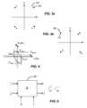
- FIG. 3which is made up of FIG. 3 a and FIG. 3 b depicts phase and gain distortion in the I/Q space.
- FIG. 4is a depiction of gain and phase error in I/Q space from which symmetry calculations can be derived.
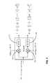
- FIG. 5is an example block diagram depicting a mixer model consistent with the present discussion.
- FIG. 6is an example block diagram depicting an I/Q correction matrix.
- FIG. 7is block diagram of a mixer correction implemented in a radio device in a manner consistent with the present discussion.
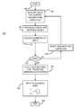
- FIG. 8is a flow chart of an example process consistent with the present teachings.
- the terms “a” or “an”, as used herein,are defined as one or more than one.
- the term “plurality”, as used herein,is defined as two or more than two.
- the term “another”, as used herein,is defined as at least a second or more.
- the terms “including” and/or “having”, as used herein,are defined as comprising (i.e., open language).
- the term “coupled”, as used herein,is defined as connected, although not necessarily directly, and not necessarily mechanically.
- programor “computer program” or “application” or similar terms, as used herein, is defined as a sequence of instructions designed for execution on a computer system.
- a “program”, or “computer program”,may include a subroutine, a function, a procedure, an object method, an object implementation, in an executable application, an applet, a servlet, a source code, an object code, a shared library/dynamic load library and/or other sequence of instructions designed for execution on a computer system.
- the term “processor”, “controller”, “CPU”, “Computer” and the like as used hereinencompasses both hard programmed, special purpose, general purpose and programmable devices and may encompass a plurality of such devices or a single device in either a distributed or centralized configuration without limitation.
- the subsetis measured for the level of radio performance in real time.
- the radio's performancecan be a measure of the symmetry of the IQ plot. It should be noted that ideally all IQ plots are symmetrical about the I and Q-axis. The level of radio performance can thus be measured in of IQ symmetry.
- a radio receiverhaving first and second mixers that mix a received communication signal to produce quadrature I and Q signals, measuring an output value of the I and Q signals
- a programmed processoris configured to carry out: evaluating symmetry in the I and Q signals by calculating a symmetry test value; iteratively testing gain and phase shift correction values by applying the gain and phase shift correction values to the I and Q signals to identify a pair of gain and phase shift correction values of the gain and phase shift correction values that produces an improved symmetry test value; selecting the pair of gain and phase shift correction values; and applying the pair of gain and phase shift correction values to the I and Q signals from the first and second mixers to generate a reduced amplitude and phase error in the output I and Q signals.
- the symmetry test valueis equal to or proportional to:
- Symmetry_test ⁇ _valueabs ⁇ ( ⁇ II ⁇ - ⁇ QQ ⁇ ) + abs ⁇ ( ⁇ IQ ⁇ ) ( ⁇ II ⁇ + ⁇ QQ ⁇ ) , where ⁇ > means average values.
- the gain and phase shift valuesare stored state variables that are tested to identify a pair of selected gain and phase shift correction values of the gain and phase shift correction values.
- the gain and phase shift valuesare applied to signals from the first and second mixers by processing with a matrix multiplication with the selected pair of gain and phase shift correction values.
- a radio receiverhaving first and second mixers that mix a received communication signal to produce quadrature I and Q signals, measuring an output value of the I and Q signals.
- a programmed processoris configured to carry out evaluating symmetry in the I and Q signals by calculating a symmetry test value, where the symmetry test value is equal to or proportional to:
- Symmetry_test ⁇ _valueabs ⁇ ( ⁇ II ⁇ - ⁇ QQ ⁇ ) + abs ⁇ ( ⁇ IQ ⁇ ) ( ⁇ II ⁇ + ⁇ QQ ⁇ ) , where ⁇ > means average values; iteratively testing gain and phase shift correction values by applying the gain and phase shift values to the I and Q signals to identify a pair of gain and phase shift correction values of the gain and phase shift correction values that produces an improved symmetry test value; selecting the pair of gain and phase shift correction values, where the gain and phase shift values are stored state variables that are tested to identify the selected pair of gain and phase shift correction values; and applying the selected pair of gain and phase shift correction values to the I and Q signals from the first and second mixers.
- the gain and phase shift correction valuesare applied to signals from the first and second mixers by processing with a matrix multiplication with the gain and phase shift errors (pair of selected gain and phase shift correction values).
- An example radio devicehas a radio receiver having first and second mixers that mix a received communication signal to produce quadrature I and Q signals, measuring an output value of the I and Q signals.
- a programmed processoris programmed to: evaluate symmetry in the I and Q signals by calculating a symmetry test value; iteratively test gain and phase shift correction values by applying the gain and phase shift values to the I and Q signals to identify a pair of gain and phase shift correction values of the gain and phase shift correction values that produces an improved symmetry test value; select the pair of gain and phase shift correction values; and apply the selected pair of gain and phase shift correction values to the I and Q signals from the first and second mixers to generate a reduced amplitude and phase error in the output value of the I and Q signals.
- the symmetry test valueis equal to or proportional to:
- Symmetry_test ⁇ _valueabs ⁇ ( ⁇ II ⁇ - ⁇ QQ ⁇ ) + abs ⁇ ( ⁇ IQ ⁇ ) ( ⁇ II ⁇ + ⁇ QQ ⁇ ) , where ⁇ > means average values.
- the gain and phase shift valuesare stored state variables that are tested to identify the selected gain and phase shift correction values.
- the gain and phase shift valuesare applied to signals from the first and second mixers by processing with a matrix multiplication with the identified and selected gain and phase shift errors.
- the gain and phase shift valuesare stored state variables that are tested to identify selected gain and phase shift values.
- the gain and phase shift valuesare applied to signals from the first and second mixers by processing with a matrix multiplication with the identified and selected gain and phase shift errors.
- the gain and phase shift valuesare stored state variables that are tested to identify the selected gain and phase shift values.
- the gain and phase shift valuesare applied to signals from the first and second mixers by processing with a matrix multiplication with the identified and selected gain and phase shift errors.
- the gain and phase shift valuesare stored state variables that are tested to identify the selected gain and phase shift correction values.
- the gain and phase shift valuesare applied to signals from the first and second mixers by processing with a matrix multiplication with the identified and selected gain and phase shift errors.
- FIG. 1is an illustration of an example block diagram of a radio transceiver 104 example. This block diagram is simplified for clarity.
- radio transceiver 104has a transmitter 150 and a receiver 154 that are operatively coupled to an antenna 158 for transmission and reception.
- Transmitter 150 and receiver 154are controlled by one or more processors 170 that control operation of the radio and selection of the various state variables used to define operation of the various circuit elements making up transmitter 150 and receiver 154 .
- Processor 170utilizes memory 174 of any suitable type that stores state variable data 178 as well as various sets of instructions for control of the transceiver.
- One example set of instructions 184implements functions that adjust the state variables used by the radio in the manner discussed herein in order to improve IQ symmetry.
- the radio receiver 154has a pair of mixers 210 and 214 that produce outputs by mixing their input signal 218 with local oscillator signals 222 and 226 (which are 90 degrees out of phase) in order to produce quadrature I and Q output signals coming from the pair of mixers.
- These I and Q output signalsare a product of mixing local oscillator signals with the input signal at 218 at mixers 210 and 214 to translate the I and Q signals down to baseband in a single conversion and are the signals that are decoded after filtering at low pass filters 238 and 242 .
- the output quadrature signalsare designated ⁇ and ⁇ tilde over (Q) ⁇ in order to indicate that this signal has magnitude and/or phase errors. While this discussion presumes a single conversion radio receiver, the present techniques are equally applicable to multiple conversion receivers.
- the mixers 210 and 214may have controllable parameters that can be adjusted directly or indirectly by a processor 170 .
- Such controllable parameterscan have an effect on the amount of errors in I and Q produced at the output of the mixers and hence at the output of the filters.
- Processor 170operates based on instructions stored in a memory 174 that includes instructions 184 that estimate the I and Q errors and helps to minimize such errors.
- a methodcan be provided to estimate/measure the I and Q errors in the presence of a wanted signal during operation of the transceiver in the field. By taking this measurement, the IQ signal errors as measured by asymmetry of the IQ signals can be minimized using a closed loop approach.
- the ⁇ signal 230 and the ⁇ tilde over (Q) ⁇ signal 234would be desirable for the ⁇ signal 230 and the ⁇ tilde over (Q) ⁇ signal 234 to be processed in the radio transceiver in order to carry out reception of a transmitted communication.
- Distortions created within the mixers and filterscan cause the magnitude and phase of the ⁇ and ⁇ tilde over (Q) ⁇ signals to deviate from ideal thus reducing the SNR (signal to noise ratio).
- SNRsignal to noise ratio
- the I and Q signalsare symmetrical. This is illustrated in FIG. 3 a and FIG. 3 b by an ideal IQ plot for a four symbol system in which the solid dots such as 250 represent ideal locations of the four symbols in IQ space lying in a perfect circle.
- the magnitude of the symbolsis shifted horizontally or vertically or both. In this case, this is represented by open dots such as 260 in which the gain in the Q direction is too large in magnitude and the gain in the I direction is too small in magnitude.
- the phase error effectsresult in a shifting out of some symbols relative to the origin and shifting in of others. This causes the constellation to again be asymmetrical.
- Symmetryis as follows, making reference to FIG. 4 :
- Q aaverage(Q); % effectively the DC offset of the Q-data over a number of samples;
- I aaverage(I); % effectively the DC offset of the I-data over a number of samples;
- I maxQ+maxQ+(I) ⁇ I a /2;
- I maxQ ⁇maxQ ⁇ (I) ⁇ I a /2; %;
- I minQ ⁇minQ ⁇ (I) ⁇ I a /2;%;
- Symmetry_test(
- the I and Q datawill have an average value (i.e. the DC offset) and a spread.
- Symmetry_testabs ⁇ ( ⁇ II ⁇ - ⁇ QQ ⁇ ) + abs ⁇ ( ⁇ IQ ⁇ ) ( ⁇ II ⁇ + ⁇ QQ ⁇ ) / 2 ⁇ 100
- any of EQUATIONS 1, 2 or 3can be utilized as a test for symmetry which can be minimized by variation of state variables to achieve improvement in IQ error distortion, with EQUATION 3 being the most comprehensive of the three tests.
- the IQ imbalancecan be modeled as a gain error ⁇ and a phase error ⁇ that is induced by mismatches in the I and Q paths of the receiver.
- the mixers 210 and 214are modeled by ideal mixers with gain stages 212 and 216 having gains 2(1 ⁇ /2) and 2(1 ⁇ /2) respectively.
- the phase shiftis modeled in the oscillators as:
- a signal processing arrangement 290in which the error containing ⁇ and ⁇ tilde over (Q) ⁇ signals in the receiver can be corrected.
- the ⁇ and ⁇ tilde over (Q) ⁇ signalsare processed by the processor 170 to implement a signal processor with transfer function in the form of a matrix multiplication ⁇ ⁇ 1 which is derived from:
- This set of state variables ⁇ and ⁇are then established for use in processing the ⁇ and ⁇ tilde over (Q) ⁇ signals in processor 170 to implement a signal processor with transfer function in the form of a matrix multiplication ⁇ ⁇ 1 so as to correct the ⁇ and ⁇ tilde over (Q) ⁇ signals to be closer to I and Q.
- ⁇ and ⁇are incremented by processor 170 , the value of a symmetry_value is evaluated to determine a minimum value or a value that is adequately low.
- the same real time communication signals ⁇ and ⁇ tilde over (Q) ⁇ signalscan be used repeatedly by processor 170 in doing this evaluation if desired, or different real time communication signals can be used for each iteration.
- the example process just describedcan be expressed in an example flow chart of a process consistent with certain implementations shown as process 300 of FIG. 8 .
- the I and Q valuesare evaluated using the currently installed gain and phase shift parameters for the radio at 306 .
- a selection of gain and phase valuese.g., all of the stored possible values, or a subset thereof surrounding the current values
- a recursive process of evaluation of the symmetry of the I and Q data at 314is carried out followed by modification of the gain and phase again at 318 until the selection of various gain and phase values is completed at 322 .
- the same set of I and Q datacan be used in each set of tests if desired when optimizing the symmetry.
- the gain and phase valuesare selected for improvement in IQ distortion at 326 .
- Correctionis then applied at 330 using the signal processing of 290 as discussed previously. The process ends at 334 , but can be repeated at a later time or at periodic intervals to assure that IQ error remains acceptable.
- any module or component disclosed herein that executes instructionsmay include or otherwise have access to non-transitory and tangible computer readable media such as storage media, computer storage media, or data storage devices (removable or non-removable) such as, for example, magnetic disks, optical disks, or tape data storage, where the term “non-transitory” is intended only to exclude propagating waves and signals and does not exclude volatile memory or memory that can be rewritten.
- Computer storage mediamay include volatile and non-volatile, removable and non-removable media implemented in any method or technology for storage of information, such as computer readable instructions, data structures, program modules, or other data.
- Examples of computer storage mediainclude RAM, ROM, EEPROM, flash memory or other memory technology, CD-ROM, digital versatile disks (DVD) or other optical storage, magnetic cassettes, magnetic tape, magnetic disk storage or other magnetic storage devices, or any other medium which can be used to store the desired information and which can be accessed by an application, module, or both. Any such computer storage media may be part of the server, any component of or related to the network, backend, etc., or accessible or connectable thereto. Any application or module herein described may be implemented using computer readable/executable instructions that may be stored or otherwise held by such computer readable media.
Landscapes
- Engineering & Computer Science (AREA)
- Power Engineering (AREA)
- Digital Transmission Methods That Use Modulated Carrier Waves (AREA)
Abstract
Description
where < > means average values. In certain implementations, the symmetry test value is equal to or proportional to: Symmetry_test_value=<I>2-<Q>2, where < > means average values. In certain implementations, the symmetry test value is equal to or proportional to: Symmetry_phase=<I*Q> where < > means average values. In certain implementations, the gain and phase shift values are stored state variables that are tested to identify a pair of selected gain and phase shift correction values of the gain and phase shift correction values. In certain implementations, the gain and phase shift values are applied to signals from the first and second mixers by processing with a matrix multiplication with the selected pair of gain and phase shift correction values.
where < > means average values; iteratively testing gain and phase shift correction values by applying the gain and phase shift values to the I and Q signals to identify a pair of gain and phase shift correction values of the gain and phase shift correction values that produces an improved symmetry test value; selecting the pair of gain and phase shift correction values, where the gain and phase shift values are stored state variables that are tested to identify the selected pair of gain and phase shift correction values; and applying the selected pair of gain and phase shift correction values to the I and Q signals from the first and second mixers.
where < > means average values. In certain implementations, the symmetry test value is equal to or proportional to: Symmetry_test_value=<I>2-<Q>2, where < > means average values. In certain implementations, the symmetry test value is equal to or proportional to: Symmetry_phase=<I*Q>, where < > means average values. In certain implementations, the gain and phase shift values are stored state variables that are tested to identify the selected gain and phase shift correction values. In certain implementations, the gain and phase shift values are applied to signals from the first and second mixers by processing with a matrix multiplication with the identified and selected gain and phase shift errors. In certain implementations, the gain and phase shift values are stored state variables that are tested to identify selected gain and phase shift values. In certain implementations, the gain and phase shift values are applied to signals from the first and second mixers by processing with a matrix multiplication with the identified and selected gain and phase shift errors. In certain implementations, the gain and phase shift values are stored state variables that are tested to identify the selected gain and phase shift values. In certain implementations, the gain and phase shift values are applied to signals from the first and second mixers by processing with a matrix multiplication with the identified and selected gain and phase shift errors. In certain implementations, the gain and phase shift values are stored state variables that are tested to identify the selected gain and phase shift correction values. In certain implementations, the gain and phase shift values are applied to signals from the first and second mixers by processing with a matrix multiplication with the identified and selected gain and phase shift errors.
Symmetry_gain=(σI)2−(σQ)2=<II>−<QQ>
=<I>2−<Q>2.
Symmetry_phase=<I*Q>.
RX=I(t)cos ωRFt+Q(t)sin ωRFt
Claims (20)
Symmetry_test_value=<I>2−<Q>2
Symmetry_phase=<I*Q>
Symmetry_test_value=<I>2−<Q>2
Symmetry_phase=<I*Q>
Priority Applications (2)
| Application Number | Priority Date | Filing Date | Title |
|---|---|---|---|
| US13/832,432US8811538B1 (en) | 2013-03-15 | 2013-03-15 | IQ error correction |
| CA2844218ACA2844218C (en) | 2013-03-15 | 2014-02-27 | Iq error correction |
Applications Claiming Priority (1)
| Application Number | Priority Date | Filing Date | Title |
|---|---|---|---|
| US13/832,432US8811538B1 (en) | 2013-03-15 | 2013-03-15 | IQ error correction |
Publications (1)
| Publication Number | Publication Date |
|---|---|
| US8811538B1true US8811538B1 (en) | 2014-08-19 |
Family
ID=51301749
Family Applications (1)
| Application Number | Title | Priority Date | Filing Date |
|---|---|---|---|
| US13/832,432ActiveUS8811538B1 (en) | 2013-03-15 | 2013-03-15 | IQ error correction |
Country Status (1)
| Country | Link |
|---|---|
| US (1) | US8811538B1 (en) |
Cited By (6)
| Publication number | Priority date | Publication date | Assignee | Title |
|---|---|---|---|---|
| CN104485893A (en)* | 2014-12-23 | 2015-04-01 | 武汉邮电科学研究院 | Broadband electric signal mixer and method |
| CN109314683A (en)* | 2016-08-29 | 2019-02-05 | Ntt 电子株式会社 | Optical transport device for compensation of distortion, optical transport distortion compensating method and communication device |
| US10447523B2 (en) | 2016-07-06 | 2019-10-15 | Nxp B.V. | IQ mismatch correction module |
| EP3579433A4 (en)* | 2017-02-03 | 2019-12-25 | JVC Kenwood Corporation | RECEPTION APPARATUS, RECEPTION METHOD AND PROGRAM |
| US10601630B1 (en) | 2019-06-10 | 2020-03-24 | Robert Dickerman | Quadrature signal imbalance estimation |
| US20230421426A1 (en)* | 2022-06-24 | 2023-12-28 | Kapsch Trafficcom Ag | Method for Calibrating an SSB Receiver |
Citations (80)
| Publication number | Priority date | Publication date | Assignee | Title |
|---|---|---|---|---|
| US5726597A (en) | 1996-08-30 | 1998-03-10 | Motorola, Inc. | Method and circuit for reducing offset voltages for a differential input stage |
| US5749051A (en) | 1996-07-18 | 1998-05-05 | Ericsson Inc. | Compensation for second order intermodulation in a homodyne receiver |
| US6242963B1 (en) | 1999-09-09 | 2001-06-05 | Atheros Communications, Inc. | Differential mixer with improved linearity |
| US20020197975A1 (en) | 2001-05-18 | 2002-12-26 | Resonext Communications, Inc. | Method for calibrating a DC offset cancellation level for direct conversion receivers |
| US6590438B1 (en) | 2002-03-08 | 2003-07-08 | Sirific Wireless Corporation | Integrated circuit adjustable RF mixer |
| US20030143967A1 (en)* | 2002-01-25 | 2003-07-31 | Ciccarelli Steven C. | AMPS receiver system using a zero-IF architecture |
| US6639446B2 (en) | 2001-09-05 | 2003-10-28 | Mitsubishi Denki Kabushiki Kaisha | High linearity, high gain mixer circuit |
| US20030206603A1 (en) | 2002-05-03 | 2003-11-06 | Husted Paul J. | Systems and methods to provide wideband magnitude and phase imbalance calibration and compensation in quadrature receivers |
| US20040152435A1 (en) | 2002-11-26 | 2004-08-05 | Stmicroelectronics Sa | Process for reducing the second-order nonlinearity of a frequency transposition device and corresponding device |
| US20040259519A1 (en) | 2003-06-22 | 2004-12-23 | Tung-Ming Su | Passive harmonic switch mixer |
| US6859085B2 (en) | 2002-09-27 | 2005-02-22 | Matsushita Electric Industrial Co., Ltd. | Mixer circuit and differential amplifier circuit |
| US20050110567A1 (en)* | 2003-11-25 | 2005-05-26 | Powerwave Technologies, Inc. | System and method of pilot tone reuse in a feedforward amplifier |
| US20050130619A1 (en) | 2003-11-05 | 2005-06-16 | Andre Hanke | Radio-frequency mixer arrangement |
| US20050135521A1 (en) | 2003-12-23 | 2005-06-23 | Elias Nemer | Method and apparatus for compensating I/Q imbalance in receivers |
| US20050143044A1 (en) | 2003-12-30 | 2005-06-30 | Samsung Electronics Co., Ltd. | Circuit for reducing second order intermodulation |
| US20050232377A1 (en) | 2002-02-27 | 2005-10-20 | Gideon Kutz | Channel estimation in a radio receiver |
| US20050239430A1 (en) | 2004-03-12 | 2005-10-27 | Rf Magic, Inc. | Harmonic suppression mixer and tuner |
| US20060014515A1 (en) | 2004-07-14 | 2006-01-19 | Ruelke Charles R | Dynamically matched mixer system with improved in-phase and quadrature (I/Q) balance and second order intercept point (IP2) performance |
| US20060039506A1 (en) | 2002-12-09 | 2006-02-23 | D Alessandro Pierluigi | Phase/gain imbalance estimation or compensation |
| US7006447B1 (en) | 2000-04-27 | 2006-02-28 | Nokia Mobile Phones Ltd. | Apparatus, and associated method, for measuring radio operating characteristics of a radio device |
| US20060094361A1 (en) | 2004-10-29 | 2006-05-04 | Hooman Darabi | Method and system for process, voltage, and temperature (PVT) measurement and calibration |
| US7164901B2 (en) | 2003-12-24 | 2007-01-16 | Agency For Science, Technology And Research | DC offset-free RF front-end circuits and systems for direct conversion receivers |
| US7171185B2 (en) | 2002-01-29 | 2007-01-30 | Matsushita Electric Industrial Co., Ltd. | Direct conversion receiver and DC offset reducing method |
| US7203476B2 (en) | 2004-01-09 | 2007-04-10 | Motorola, Inc. | Method and apparatus for minimizing baseband offset error in a receiver |
| US20070126491A1 (en) | 2005-12-06 | 2007-06-07 | Samsung Electronics Co., Ltd. | CMOS mixer for use in direct conversion receiver |
| US7242910B2 (en) | 2003-02-03 | 2007-07-10 | M/A-Com, Inc. | Self-calibrating radio |
| US7259569B2 (en) | 2005-01-05 | 2007-08-21 | Samsung Electronics Co., Ltd. | Calibration circuit and method thereof |
| US7292836B2 (en) | 2002-12-30 | 2007-11-06 | Evolium S.A.S. | Direct conversion receiver |
| US7346134B2 (en) | 2001-05-15 | 2008-03-18 | Finesse Wireless, Inc. | Radio receiver |
| US7346313B2 (en) | 2002-03-04 | 2008-03-18 | Cafarella John H | Calibration of I-Q balance in transceivers |
| US7369837B2 (en) | 2004-08-17 | 2008-05-06 | Samsung Electronics, Co., Ltd. | Frequency-mixing method and frequency-mixing device using the same |
| US20080116902A1 (en) | 2006-11-22 | 2008-05-22 | Kim Hyun-Seok | Second intercept point (ip2) calibrator and method for calibrating ip2 |
| US7415253B2 (en) | 2004-06-28 | 2008-08-19 | Broadcom Corporation | Temperature compensation of transmit power of a wireless communication device |
| US7440742B1 (en) | 2002-11-11 | 2008-10-21 | Marvell International Ltd. | Mixer gain calibration method and apparatus |
| US7447490B2 (en) | 2005-05-18 | 2008-11-04 | Nvidia Corporation | In-situ gain calibration of radio frequency devices using thermal noise |
| US7450918B2 (en) | 2004-10-11 | 2008-11-11 | Samsung Electronics Co., Ltd. | Apparatus and method for controlling gain of a transceiving device in a wireless terminal for a communication system |
| US7457606B2 (en) | 2004-01-30 | 2008-11-25 | Samsung Electronics Co., Ltd. | Mixer circuit for direct conversion transceiver with improved IP2 |
| US7477888B2 (en) | 2002-01-07 | 2009-01-13 | Broadcom Corporation | Low noise and low voltage mixer and intermediate frequency module application thereof |
| US7496340B1 (en) | 2005-06-02 | 2009-02-24 | Rf Micro Devices, Inc. | I/Q mismatch calibration of direct conversion receivers using radio frequency noise |
| US7496343B2 (en) | 2002-02-15 | 2009-02-24 | Broadcom Corporation | Programmable mixer for reducing local oscillator feedthrough and radio applications thereof |
| US20090068974A1 (en) | 2007-09-06 | 2009-03-12 | Smith Francis J | Multi-mode - multi-band direct conversion receiver with complex i and q channel interference mitigation processing for cancellation of intermodulation products |
| US7509112B2 (en) | 2004-11-16 | 2009-03-24 | Avago Technologies Wireless Ip (Singapore) Pte. Ltd. | Wideband image rejection mixer |
| US7522899B1 (en) | 2004-07-15 | 2009-04-21 | Marvell International Ltd. | Image rejection scheme for receivers |
| US7532874B2 (en) | 2005-11-09 | 2009-05-12 | Texas Instruments Incorporated | Offset balancer, method of balancing an offset and a wireless receiver employing the balancer and the method |
| US7532563B1 (en) | 2003-11-25 | 2009-05-12 | Marvell International Ltd. | Mechanism to improve quality of channel estimates in OFDM transmissions |
| US7542100B2 (en) | 2004-04-30 | 2009-06-02 | Telegent Systems, Inc. | Video receiver with adaptive image rejection |
| US7542751B2 (en) | 2005-12-12 | 2009-06-02 | Mediatek Inc. | Down-converter and calibration method thereof |
| US20090143031A1 (en) | 2005-03-11 | 2009-06-04 | Peter Shah | Harmonic suppression mixer and tuner |
| US7554380B2 (en) | 2005-12-12 | 2009-06-30 | Icera Canada ULC | System for reducing second order intermodulation products from differential circuits |
| US7567611B2 (en) | 2002-09-05 | 2009-07-28 | Silicon Storage Technology, Inc. | Compensation of I-Q imbalance in digital transceivers |
| US7570965B2 (en) | 2006-09-29 | 2009-08-04 | Broadcom Corporation | Method and system for compensating for using a transmitter to calibrate a receiver for channel equalization |
| US20090202022A1 (en) | 2008-02-08 | 2009-08-13 | Kaczman Daniel L | Split channel receiver with very low second order intermodulation |
| US20090239495A1 (en) | 2008-03-19 | 2009-09-24 | Skyworks Solutions, Inc. | Dc-compensated ip2 calibration for wcdma receiver |
| US20090280767A1 (en) | 2008-05-09 | 2009-11-12 | Fredrik Tillman | Time-multiplexed common mode feedback for passive quadrature rf mixers |
| US20090325529A1 (en) | 2008-06-26 | 2009-12-31 | Xuebin Yang | Calibrating receive chain to reduce second order intermodulation distortion |
| US20100067622A1 (en) | 2008-09-15 | 2010-03-18 | Skyworks Solutions, Inc. | Circuit, Controller and Methods for Dynamic Estimation and Cancellation of Phase and Gain Imbalances in Quadrature Signal Paths of a Receiver |
| US20100093298A1 (en) | 2008-10-09 | 2010-04-15 | Freescale Semiconductor, Inc. | Adaptive iip2 calibration |
| US20100120369A1 (en) | 2008-11-13 | 2010-05-13 | Qualcomm Incorporated | Rf transceiver ic having internal loopback conductor for ip2 self test |
| US20100167683A1 (en) | 2003-08-28 | 2010-07-01 | Broadcom Corporation | Apparatus and Method for Local Oscillator Calibration in Mixer Circuits |
| US7787853B2 (en) | 2006-07-07 | 2010-08-31 | Stmicroelectronics Sa | Method and device for the reduction of the DC component of a signal transposed into baseband, in particular in a receiver of the direct conversion type |
| US7890078B2 (en) | 2004-12-27 | 2011-02-15 | Advanced Micro Devices, Inc. | Dual band WLAN communication frequency synthesizer technique |
| US20110065412A1 (en) | 2009-09-16 | 2011-03-17 | Federico Alessandro Fabrizio Beffa | Mixer circuit, integrated circuit device and radio frequency communication unit |
| US20110092178A1 (en) | 2009-10-16 | 2011-04-21 | Qualcomm Incorporated | Doubled balanced mixer with improved component matching |
| US7949313B2 (en) | 2004-12-16 | 2011-05-24 | St-Ericsson Sa | Direct conversion device with compensation means for a transmission path of a wireless communication equipment |
| US20110128992A1 (en) | 2009-11-30 | 2011-06-02 | Renesas Electronics Corporation | Semiconductor integrated communication circuit and operation method thereof |
| US20110151792A1 (en) | 2009-12-18 | 2011-06-23 | Lee & Hayes, PLLC | Method for second intercept point calibration based on opportunistic reception |
| US20110201296A1 (en) | 2008-02-08 | 2011-08-18 | Freescale Semiconductor, Inc. | Mixer circuits for second order intercept point calibration |
| US8010077B2 (en) | 2008-04-21 | 2011-08-30 | Freescale Semiconductor, Inc. | DC offset calibration in a direct conversion receiver |
| US20110230157A1 (en) | 2008-11-27 | 2011-09-22 | Huawei Technologies Co., Ltd. | Equivalent radio frequency notch filter, radio frequency chip, and receiver |
| US8045943B2 (en) | 2008-01-29 | 2011-10-25 | Freescale Semiconductor, Inc. | High performance CMOS radio frequency receiver |
| US20110299575A1 (en) | 2008-12-12 | 2011-12-08 | St-Ericsson Sa | Method and system of calibration of a second order intermodulation intercept point of a radio transceiver |
| US20120002770A1 (en) | 2009-04-03 | 2012-01-05 | Panasonic Corporation | Second-order distortion correcting receiver and second-order distortion correcting method |
| US8107368B2 (en) | 2006-10-03 | 2012-01-31 | Viasat, Inc. | Large packet concatenation in satellite communication system |
| US8149902B1 (en) | 2007-09-13 | 2012-04-03 | Maxim Integrated Products, Inc. | Methods to relax the second order intercept point of transceivers |
| US8149955B2 (en) | 2008-06-30 | 2012-04-03 | Telefonaktiebolaget L M Ericsson (Publ) | Single ended multiband feedback linearized RF amplifier and mixer with DC-offset and IM2 suppression feedback loop |
| US20120088532A1 (en) | 2010-10-11 | 2012-04-12 | Motorola, Inc. | Method and apparatus for radio frequency fingerprint distribution |
| US20120238232A1 (en) | 2011-03-17 | 2012-09-20 | David Murphy | Method and system for low-noise, highly-linear receiver front-end |
| US20120252374A1 (en) | 2009-10-23 | 2012-10-04 | Sven Mattisson | Passive Mixer with Reduced Second Order Intermodulation |
| US20130029626A1 (en) | 2011-07-26 | 2013-01-31 | Mstar Semiconductor, Inc. | Direct Conversion Receiver and Calibration Method Thereof |
| US20130231124A1 (en) | 2011-08-31 | 2013-09-05 | Research In Motion Limited | Method and system for spectrum sensing and low overhead feedback |
- 2013
- 2013-03-15USUS13/832,432patent/US8811538B1/enactiveActive
Patent Citations (101)
| Publication number | Priority date | Publication date | Assignee | Title |
|---|---|---|---|---|
| US5749051A (en) | 1996-07-18 | 1998-05-05 | Ericsson Inc. | Compensation for second order intermodulation in a homodyne receiver |
| US5726597A (en) | 1996-08-30 | 1998-03-10 | Motorola, Inc. | Method and circuit for reducing offset voltages for a differential input stage |
| US6242963B1 (en) | 1999-09-09 | 2001-06-05 | Atheros Communications, Inc. | Differential mixer with improved linearity |
| US7006447B1 (en) | 2000-04-27 | 2006-02-28 | Nokia Mobile Phones Ltd. | Apparatus, and associated method, for measuring radio operating characteristics of a radio device |
| US7346134B2 (en) | 2001-05-15 | 2008-03-18 | Finesse Wireless, Inc. | Radio receiver |
| US20020197975A1 (en) | 2001-05-18 | 2002-12-26 | Resonext Communications, Inc. | Method for calibrating a DC offset cancellation level for direct conversion receivers |
| US6941121B2 (en) | 2001-05-18 | 2005-09-06 | Rf Micro Devices, Inc. | Method for calibrating a DC offset cancellation level for direct conversion receivers |
| US6639446B2 (en) | 2001-09-05 | 2003-10-28 | Mitsubishi Denki Kabushiki Kaisha | High linearity, high gain mixer circuit |
| US7477888B2 (en) | 2002-01-07 | 2009-01-13 | Broadcom Corporation | Low noise and low voltage mixer and intermediate frequency module application thereof |
| US20030143967A1 (en)* | 2002-01-25 | 2003-07-31 | Ciccarelli Steven C. | AMPS receiver system using a zero-IF architecture |
| US7171185B2 (en) | 2002-01-29 | 2007-01-30 | Matsushita Electric Industrial Co., Ltd. | Direct conversion receiver and DC offset reducing method |
| US7496343B2 (en) | 2002-02-15 | 2009-02-24 | Broadcom Corporation | Programmable mixer for reducing local oscillator feedthrough and radio applications thereof |
| US20050232377A1 (en) | 2002-02-27 | 2005-10-20 | Gideon Kutz | Channel estimation in a radio receiver |
| US7965796B2 (en) | 2002-02-27 | 2011-06-21 | Freescale Semiconductor, Inc. | Channel estimation in a radio receiver |
| US7346313B2 (en) | 2002-03-04 | 2008-03-18 | Cafarella John H | Calibration of I-Q balance in transceivers |
| US6590438B1 (en) | 2002-03-08 | 2003-07-08 | Sirific Wireless Corporation | Integrated circuit adjustable RF mixer |
| US20030206603A1 (en) | 2002-05-03 | 2003-11-06 | Husted Paul J. | Systems and methods to provide wideband magnitude and phase imbalance calibration and compensation in quadrature receivers |
| US7567611B2 (en) | 2002-09-05 | 2009-07-28 | Silicon Storage Technology, Inc. | Compensation of I-Q imbalance in digital transceivers |
| US6859085B2 (en) | 2002-09-27 | 2005-02-22 | Matsushita Electric Industrial Co., Ltd. | Mixer circuit and differential amplifier circuit |
| US7440742B1 (en) | 2002-11-11 | 2008-10-21 | Marvell International Ltd. | Mixer gain calibration method and apparatus |
| US20040152435A1 (en) | 2002-11-26 | 2004-08-05 | Stmicroelectronics Sa | Process for reducing the second-order nonlinearity of a frequency transposition device and corresponding device |
| US20060039506A1 (en) | 2002-12-09 | 2006-02-23 | D Alessandro Pierluigi | Phase/gain imbalance estimation or compensation |
| US7292836B2 (en) | 2002-12-30 | 2007-11-06 | Evolium S.A.S. | Direct conversion receiver |
| US7242910B2 (en) | 2003-02-03 | 2007-07-10 | M/A-Com, Inc. | Self-calibrating radio |
| US20040259519A1 (en) | 2003-06-22 | 2004-12-23 | Tung-Ming Su | Passive harmonic switch mixer |
| US20100167683A1 (en) | 2003-08-28 | 2010-07-01 | Broadcom Corporation | Apparatus and Method for Local Oscillator Calibration in Mixer Circuits |
| US7218163B2 (en) | 2003-11-05 | 2007-05-15 | Infineon Technologies Ag | Radio-frequency mixer arrangement |
| US20050130619A1 (en) | 2003-11-05 | 2005-06-16 | Andre Hanke | Radio-frequency mixer arrangement |
| US7532563B1 (en) | 2003-11-25 | 2009-05-12 | Marvell International Ltd. | Mechanism to improve quality of channel estimates in OFDM transmissions |
| US20050110567A1 (en)* | 2003-11-25 | 2005-05-26 | Powerwave Technologies, Inc. | System and method of pilot tone reuse in a feedforward amplifier |
| US20050135521A1 (en) | 2003-12-23 | 2005-06-23 | Elias Nemer | Method and apparatus for compensating I/Q imbalance in receivers |
| US7164901B2 (en) | 2003-12-24 | 2007-01-16 | Agency For Science, Technology And Research | DC offset-free RF front-end circuits and systems for direct conversion receivers |
| US20050143044A1 (en) | 2003-12-30 | 2005-06-30 | Samsung Electronics Co., Ltd. | Circuit for reducing second order intermodulation |
| US7421263B2 (en) | 2003-12-30 | 2008-09-02 | Samsung Electronics Co., Ltd. | Circuit for reducing second order intermodulation |
| US7203476B2 (en) | 2004-01-09 | 2007-04-10 | Motorola, Inc. | Method and apparatus for minimizing baseband offset error in a receiver |
| US7457606B2 (en) | 2004-01-30 | 2008-11-25 | Samsung Electronics Co., Ltd. | Mixer circuit for direct conversion transceiver with improved IP2 |
| US20050239430A1 (en) | 2004-03-12 | 2005-10-27 | Rf Magic, Inc. | Harmonic suppression mixer and tuner |
| US7519348B2 (en) | 2004-03-12 | 2009-04-14 | Rf Magic, Inc. | Harmonic suppression mixer and tuner |
| US7542100B2 (en) | 2004-04-30 | 2009-06-02 | Telegent Systems, Inc. | Video receiver with adaptive image rejection |
| US7415253B2 (en) | 2004-06-28 | 2008-08-19 | Broadcom Corporation | Temperature compensation of transmit power of a wireless communication device |
| US7251468B2 (en) | 2004-07-14 | 2007-07-31 | Motorola, Inc. | Dynamically matched mixer system with improved in-phase and quadrature (I/Q) balance and second order intercept point (IP2) performance |
| US20060014515A1 (en) | 2004-07-14 | 2006-01-19 | Ruelke Charles R | Dynamically matched mixer system with improved in-phase and quadrature (I/Q) balance and second order intercept point (IP2) performance |
| US7522899B1 (en) | 2004-07-15 | 2009-04-21 | Marvell International Ltd. | Image rejection scheme for receivers |
| US7369837B2 (en) | 2004-08-17 | 2008-05-06 | Samsung Electronics, Co., Ltd. | Frequency-mixing method and frequency-mixing device using the same |
| US7450918B2 (en) | 2004-10-11 | 2008-11-11 | Samsung Electronics Co., Ltd. | Apparatus and method for controlling gain of a transceiving device in a wireless terminal for a communication system |
| US20090004983A1 (en) | 2004-10-29 | 2009-01-01 | Broadcom Corporation | Method and system for a second order input intercept point (iip2) correction |
| US20060094361A1 (en) | 2004-10-29 | 2006-05-04 | Hooman Darabi | Method and system for process, voltage, and temperature (PVT) measurement and calibration |
| US7421260B2 (en) | 2004-10-29 | 2008-09-02 | Broadcom Corporation | Method and system for a second order input intercept point (IIP2) correction |
| US7869777B2 (en) | 2004-10-29 | 2011-01-11 | Broadcom Corporation | Method and system for a second order input intercept point (IIP2) correction |
| US7509112B2 (en) | 2004-11-16 | 2009-03-24 | Avago Technologies Wireless Ip (Singapore) Pte. Ltd. | Wideband image rejection mixer |
| US7949313B2 (en) | 2004-12-16 | 2011-05-24 | St-Ericsson Sa | Direct conversion device with compensation means for a transmission path of a wireless communication equipment |
| US7890078B2 (en) | 2004-12-27 | 2011-02-15 | Advanced Micro Devices, Inc. | Dual band WLAN communication frequency synthesizer technique |
| US7259569B2 (en) | 2005-01-05 | 2007-08-21 | Samsung Electronics Co., Ltd. | Calibration circuit and method thereof |
| US20090143031A1 (en) | 2005-03-11 | 2009-06-04 | Peter Shah | Harmonic suppression mixer and tuner |
| US7447490B2 (en) | 2005-05-18 | 2008-11-04 | Nvidia Corporation | In-situ gain calibration of radio frequency devices using thermal noise |
| US7496340B1 (en) | 2005-06-02 | 2009-02-24 | Rf Micro Devices, Inc. | I/Q mismatch calibration of direct conversion receivers using radio frequency noise |
| US7532874B2 (en) | 2005-11-09 | 2009-05-12 | Texas Instruments Incorporated | Offset balancer, method of balancing an offset and a wireless receiver employing the balancer and the method |
| US20070126491A1 (en) | 2005-12-06 | 2007-06-07 | Samsung Electronics Co., Ltd. | CMOS mixer for use in direct conversion receiver |
| US7542751B2 (en) | 2005-12-12 | 2009-06-02 | Mediatek Inc. | Down-converter and calibration method thereof |
| US7554380B2 (en) | 2005-12-12 | 2009-06-30 | Icera Canada ULC | System for reducing second order intermodulation products from differential circuits |
| US7787853B2 (en) | 2006-07-07 | 2010-08-31 | Stmicroelectronics Sa | Method and device for the reduction of the DC component of a signal transposed into baseband, in particular in a receiver of the direct conversion type |
| US7570965B2 (en) | 2006-09-29 | 2009-08-04 | Broadcom Corporation | Method and system for compensating for using a transmitter to calibrate a receiver for channel equalization |
| US8107368B2 (en) | 2006-10-03 | 2012-01-31 | Viasat, Inc. | Large packet concatenation in satellite communication system |
| US8000676B2 (en) | 2006-11-22 | 2011-08-16 | Samsung Electronics Co., Ltd. | Second intercept point (IP2) calibrator and method for calibrating IP2 |
| US20080116902A1 (en) | 2006-11-22 | 2008-05-22 | Kim Hyun-Seok | Second intercept point (ip2) calibrator and method for calibrating ip2 |
| US20090068974A1 (en) | 2007-09-06 | 2009-03-12 | Smith Francis J | Multi-mode - multi-band direct conversion receiver with complex i and q channel interference mitigation processing for cancellation of intermodulation products |
| US7773967B2 (en) | 2007-09-06 | 2010-08-10 | Francis J. Smith | Multi-mode—multi-band direct conversion receiver with complex I and Q channel interference mitigation processing for cancellation of intermodulation products |
| US8149902B1 (en) | 2007-09-13 | 2012-04-03 | Maxim Integrated Products, Inc. | Methods to relax the second order intercept point of transceivers |
| US8045943B2 (en) | 2008-01-29 | 2011-10-25 | Freescale Semiconductor, Inc. | High performance CMOS radio frequency receiver |
| US8073078B2 (en) | 2008-02-08 | 2011-12-06 | Freescale Semiconductor, Inc. | Split channel receiver with very low second order intermodulation |
| US20090202022A1 (en) | 2008-02-08 | 2009-08-13 | Kaczman Daniel L | Split channel receiver with very low second order intermodulation |
| US20110201296A1 (en) | 2008-02-08 | 2011-08-18 | Freescale Semiconductor, Inc. | Mixer circuits for second order intercept point calibration |
| US7929938B2 (en) | 2008-03-19 | 2011-04-19 | Skyworks Solutions, Inc. | DC-compensated IP2 calibration for WCDMA receiver |
| US20090239495A1 (en) | 2008-03-19 | 2009-09-24 | Skyworks Solutions, Inc. | Dc-compensated ip2 calibration for wcdma receiver |
| US8010077B2 (en) | 2008-04-21 | 2011-08-30 | Freescale Semiconductor, Inc. | DC offset calibration in a direct conversion receiver |
| US8150360B2 (en) | 2008-04-21 | 2012-04-03 | Freescale Semiconductor, Inc. | DC offset calibration in a direct conversion receiver |
| US7945230B2 (en) | 2008-05-09 | 2011-05-17 | Telefonaktiebolaget Lm Ericsson (Publ) | Time-multiplexed common mode feedback for passive quadrature RF mixers |
| US20090280767A1 (en) | 2008-05-09 | 2009-11-12 | Fredrik Tillman | Time-multiplexed common mode feedback for passive quadrature rf mixers |
| US8112055B2 (en) | 2008-06-26 | 2012-02-07 | Intel Corporation | Calibrating receive chain to reduce second order intermodulation distortion |
| US20090325529A1 (en) | 2008-06-26 | 2009-12-31 | Xuebin Yang | Calibrating receive chain to reduce second order intermodulation distortion |
| US8149955B2 (en) | 2008-06-30 | 2012-04-03 | Telefonaktiebolaget L M Ericsson (Publ) | Single ended multiband feedback linearized RF amplifier and mixer with DC-offset and IM2 suppression feedback loop |
| US20100067622A1 (en) | 2008-09-15 | 2010-03-18 | Skyworks Solutions, Inc. | Circuit, Controller and Methods for Dynamic Estimation and Cancellation of Phase and Gain Imbalances in Quadrature Signal Paths of a Receiver |
| US8150350B2 (en) | 2008-10-09 | 2012-04-03 | Freescale Semiconductor, Inc. | Adaptive IIP2 calibration |
| US8060043B2 (en) | 2008-10-09 | 2011-11-15 | Freescale Semiconductor | Adaptive IIP2 calibration |
| US20100093298A1 (en) | 2008-10-09 | 2010-04-15 | Freescale Semiconductor, Inc. | Adaptive iip2 calibration |
| US20120015616A1 (en) | 2008-10-09 | 2012-01-19 | Freescale Semiconductor, Inc. | Adaptive iip2 calibration |
| US20100120369A1 (en) | 2008-11-13 | 2010-05-13 | Qualcomm Incorporated | Rf transceiver ic having internal loopback conductor for ip2 self test |
| US20110230157A1 (en) | 2008-11-27 | 2011-09-22 | Huawei Technologies Co., Ltd. | Equivalent radio frequency notch filter, radio frequency chip, and receiver |
| US20110299575A1 (en) | 2008-12-12 | 2011-12-08 | St-Ericsson Sa | Method and system of calibration of a second order intermodulation intercept point of a radio transceiver |
| US20120002770A1 (en) | 2009-04-03 | 2012-01-05 | Panasonic Corporation | Second-order distortion correcting receiver and second-order distortion correcting method |
| US8112059B2 (en) | 2009-09-16 | 2012-02-07 | Mediatek Singapore Pte. Ltd. | Mixer circuit, integrated circuit device and radio frequency communication unit |
| US20110065412A1 (en) | 2009-09-16 | 2011-03-17 | Federico Alessandro Fabrizio Beffa | Mixer circuit, integrated circuit device and radio frequency communication unit |
| US20110092178A1 (en) | 2009-10-16 | 2011-04-21 | Qualcomm Incorporated | Doubled balanced mixer with improved component matching |
| US20120252374A1 (en) | 2009-10-23 | 2012-10-04 | Sven Mattisson | Passive Mixer with Reduced Second Order Intermodulation |
| US20110128992A1 (en) | 2009-11-30 | 2011-06-02 | Renesas Electronics Corporation | Semiconductor integrated communication circuit and operation method thereof |
| US8121571B2 (en) | 2009-12-18 | 2012-02-21 | Igal Kushnir | Method for second intercept point calibration based on opportunistic reception |
| US20110151792A1 (en) | 2009-12-18 | 2011-06-23 | Lee & Hayes, PLLC | Method for second intercept point calibration based on opportunistic reception |
| US20120088532A1 (en) | 2010-10-11 | 2012-04-12 | Motorola, Inc. | Method and apparatus for radio frequency fingerprint distribution |
| US20120238232A1 (en) | 2011-03-17 | 2012-09-20 | David Murphy | Method and system for low-noise, highly-linear receiver front-end |
| US20130029626A1 (en) | 2011-07-26 | 2013-01-31 | Mstar Semiconductor, Inc. | Direct Conversion Receiver and Calibration Method Thereof |
| US20130231124A1 (en) | 2011-08-31 | 2013-09-05 | Research In Motion Limited | Method and system for spectrum sensing and low overhead feedback |
Non-Patent Citations (5)
| Title |
|---|
| European Search Report, EP13159314.7, Jul. 22, 2013. |
| European Search Report, EP13159316.2, Jul. 24, 2013. |
| Giugno et al., "Efficient compensation of I/Q phase imbalance for digital receivers", 2005 IEEE International Conference on Communications, vol. 4, May 16, 2005, pp. 2462-2466. |
| IQ Imbalance Compensation in OFDMA based WiMAX Digital Receivers Wang Lilei; Xu Huimin, Computer Science and Information Technology, 2008. ICCSIT apos;08. International Conference on Volume , Issue , Aug. 29, 2008-Sep. 2, 2008 pp. 388-392. |
| P. Rykaczewski, "Non-data-aided IQ imbalance compensation using measured receiver front-end signals", the 17th Annual IEEE Int. Sym on Personal, Indoor and Mobile Radio Com., 2006. |
Cited By (9)
| Publication number | Priority date | Publication date | Assignee | Title |
|---|---|---|---|---|
| CN104485893A (en)* | 2014-12-23 | 2015-04-01 | 武汉邮电科学研究院 | Broadband electric signal mixer and method |
| CN104485893B (en)* | 2014-12-23 | 2017-10-10 | 武汉邮电科学研究院 | Wideband electrical signal frequency mixer and method |
| US10447523B2 (en) | 2016-07-06 | 2019-10-15 | Nxp B.V. | IQ mismatch correction module |
| CN109314683A (en)* | 2016-08-29 | 2019-02-05 | Ntt 电子株式会社 | Optical transport device for compensation of distortion, optical transport distortion compensating method and communication device |
| US10374718B2 (en)* | 2016-08-29 | 2019-08-06 | Ntt Electronics Corporation | Optical transmission distortion compensation device, optical transmission distortion compensation method, and communication device |
| EP3579433A4 (en)* | 2017-02-03 | 2019-12-25 | JVC Kenwood Corporation | RECEPTION APPARATUS, RECEPTION METHOD AND PROGRAM |
| US10601630B1 (en) | 2019-06-10 | 2020-03-24 | Robert Dickerman | Quadrature signal imbalance estimation |
| US20230421426A1 (en)* | 2022-06-24 | 2023-12-28 | Kapsch Trafficcom Ag | Method for Calibrating an SSB Receiver |
| US12323280B2 (en)* | 2022-06-24 | 2025-06-03 | Kapsch Trafficcom Ag | Method for calibrating an SSB receiver |
Similar Documents
| Publication | Publication Date | Title |
|---|---|---|
| US8811538B1 (en) | IQ error correction | |
| US9998242B2 (en) | Second order intercept point (IP2) calibration for wireless receivers | |
| KR101196519B1 (en) | Transmitter, wireless communication element, and method for spurious emission cancellation | |
| CN101815056B (en) | IQ unbalanced calibration method and equipment of baseband signals in wireless communication receiving machine | |
| US7010278B2 (en) | Sideband suppression method and apparatus for quadrature modulator using magnitude measurements | |
| US8000382B2 (en) | I/Q imbalance estimation and correction in a communication system | |
| US20170176507A1 (en) | Active antenna system and methods of determining intermodulation distortion performance | |
| US20150350000A1 (en) | Calibration method and calibration apparatus for calibrating mismatch between first signal path and second signal path of transmitter/receiver | |
| US8953711B2 (en) | Configurable pre-emphasis component for transmission circuitry | |
| EP3167553A1 (en) | Cancelling intermodulation interference | |
| TWI487296B (en) | Fast lo leakage calibration of direct up-conversion transmitters using three measurements | |
| CN105264813A (en) | Quadrature error detection and correction | |
| CN105656834A (en) | Digital correction method for IQ channel mismatch of novel broadband receiver | |
| US20230370172A1 (en) | Correcting error vector magnitude measurements | |
| JP2022524455A (en) | Sideband suppression methods, devices, computer equipment and computer programs | |
| US20180083661A1 (en) | Wideband Residual Sideband Calibration | |
| US20140010271A1 (en) | Signal processing for diversity combining radio receiver | |
| US9698840B2 (en) | Receiver and a method for reducing a distortion component related to a baseband transmit signal in a baseband receive signal | |
| TW200901691A (en) | Channel estimation using frequency smoothing | |
| US8942656B2 (en) | Reduction of second order distortion in real time | |
| CA2844218C (en) | Iq error correction | |
| Lira de Queiroz et al. | Signal-to-noise ratio estimation for M-QAM signals in η− μ and κ− μ fading channels | |
| EP2779563A1 (en) | Iq error correction | |
| Rodriguez-Avila et al. | A frequency-selective I/Q imbalance analysis technique | |
| Hudlička et al. | Characterization of a 300-GHz transmission system for digital communications |
Legal Events
| Date | Code | Title | Description |
|---|---|---|---|
| AS | Assignment | Owner name:RESEARCH IN MOTION LIMITED, CANADA Free format text:ASSIGNMENT OF ASSIGNORS INTEREST;ASSIGNOR:MANKU, TAJINDER;REEL/FRAME:030560/0275 Effective date:20130530 | |
| AS | Assignment | Owner name:BLACKBERRY LIMITED, ONTARIO Free format text:CHANGE OF NAME;ASSIGNOR:RESEARCH IN MOTION LIMITED;REEL/FRAME:033134/0228 Effective date:20130709 | |
| STCF | Information on status: patent grant | Free format text:PATENTED CASE | |
| MAFP | Maintenance fee payment | Free format text:PAYMENT OF MAINTENANCE FEE, 4TH YEAR, LARGE ENTITY (ORIGINAL EVENT CODE: M1551) Year of fee payment:4 | |
| MAFP | Maintenance fee payment | Free format text:PAYMENT OF MAINTENANCE FEE, 8TH YEAR, LARGE ENTITY (ORIGINAL EVENT CODE: M1552); ENTITY STATUS OF PATENT OWNER: LARGE ENTITY Year of fee payment:8 | |
| AS | Assignment | Owner name:MALIKIE INNOVATIONS LIMITED, IRELAND Free format text:ASSIGNMENT OF ASSIGNORS INTEREST;ASSIGNOR:BLACKBERRY LIMITED;REEL/FRAME:064104/0103 Effective date:20230511 | |
| AS | Assignment | Owner name:MALIKIE INNOVATIONS LIMITED, IRELAND Free format text:NUNC PRO TUNC ASSIGNMENT;ASSIGNOR:BLACKBERRY LIMITED;REEL/FRAME:064270/0001 Effective date:20230511 |