US8811356B2 - Communications in a wireless network - Google Patents
Communications in a wireless networkDownload PDFInfo
- Publication number
- US8811356B2 US8811356B2US13/176,298US201113176298AUS8811356B2US 8811356 B2US8811356 B2US 8811356B2US 201113176298 AUS201113176298 AUS 201113176298AUS 8811356 B2US8811356 B2US 8811356B2
- Authority
- US
- United States
- Prior art keywords
- physical
- control channel
- uplink
- channel
- shared channel
- Prior art date
- Legal status (The legal status is an assumption and is not a legal conclusion. Google has not performed a legal analysis and makes no representation as to the accuracy of the status listed.)
- Active, expires
Links
- 238000004891communicationMethods0.000titledescription19
- 238000013468resource allocationMethods0.000claimsabstract18
- 238000000034methodMethods0.000claimsdescription32
- 238000005194fractionationMethods0.000description13
- 230000005540biological transmissionEffects0.000description8
- 230000006870functionEffects0.000description8
- 230000008901benefitEffects0.000description7
- 238000004590computer programMethods0.000description5
- 238000012546transferMethods0.000description5
- 230000001965increasing effectEffects0.000description4
- 238000000926separation methodMethods0.000description4
- 238000001228spectrumMethods0.000description4
- 230000006978adaptationEffects0.000description3
- 230000003287optical effectEffects0.000description3
- 230000008569processEffects0.000description3
- 230000004044responseEffects0.000description3
- 230000000903blocking effectEffects0.000description2
- 230000010267cellular communicationEffects0.000description2
- 230000000694effectsEffects0.000description2
- 238000005516engineering processMethods0.000description2
- 238000012986modificationMethods0.000description2
- 230000004048modificationEffects0.000description2
- 238000012545processingMethods0.000description2
- 230000003068static effectEffects0.000description2
- 230000001360synchronised effectEffects0.000description2
- 230000001413cellular effectEffects0.000description1
- 239000012141concentrateSubstances0.000description1
- 230000001276controlling effectEffects0.000description1
- 238000007796conventional methodMethods0.000description1
- 230000003247decreasing effectEffects0.000description1
- 238000013461designMethods0.000description1
- 238000001514detection methodMethods0.000description1
- 230000002708enhancing effectEffects0.000description1
- 238000005562fadingMethods0.000description1
- 239000000835fiberSubstances0.000description1
- 230000007246mechanismEffects0.000description1
- 230000008520organizationEffects0.000description1
- 230000001105regulatory effectEffects0.000description1
Images


Classifications
- H—ELECTRICITY
- H04—ELECTRIC COMMUNICATION TECHNIQUE
- H04W—WIRELESS COMMUNICATION NETWORKS
- H04W72/00—Local resource management
- H04W72/04—Wireless resource allocation
- H04W72/044—Wireless resource allocation based on the type of the allocated resource
- H04W72/0446—Resources in time domain, e.g. slots or frames
- H—ELECTRICITY
- H04—ELECTRIC COMMUNICATION TECHNIQUE
- H04B—TRANSMISSION
- H04B7/00—Radio transmission systems, i.e. using radiation field
- H04B7/24—Radio transmission systems, i.e. using radiation field for communication between two or more posts
- H04B7/26—Radio transmission systems, i.e. using radiation field for communication between two or more posts at least one of which is mobile
- H04B7/2643—Radio transmission systems, i.e. using radiation field for communication between two or more posts at least one of which is mobile using time-division multiple access [TDMA]
- H—ELECTRICITY
- H04—ELECTRIC COMMUNICATION TECHNIQUE
- H04W—WIRELESS COMMUNICATION NETWORKS
- H04W72/00—Local resource management
- H04W72/20—Control channels or signalling for resource management
- H—ELECTRICITY
- H04—ELECTRIC COMMUNICATION TECHNIQUE
- H04J—MULTIPLEX COMMUNICATION
- H04J3/00—Time-division multiplex systems
- H04J3/16—Time-division multiplex systems in which the time allocation to individual channels within a transmission cycle is variable, e.g. to accommodate varying complexity of signals, to vary number of channels transmitted
- H04J3/1694—Allocation of channels in TDM/TDMA networks, e.g. distributed multiplexers
- H—ELECTRICITY
- H04—ELECTRIC COMMUNICATION TECHNIQUE
- H04L—TRANSMISSION OF DIGITAL INFORMATION, e.g. TELEGRAPHIC COMMUNICATION
- H04L5/00—Arrangements affording multiple use of the transmission path
- H04L5/003—Arrangements for allocating sub-channels of the transmission path
- H04L5/0053—Allocation of signalling, i.e. of overhead other than pilot signals
- H—ELECTRICITY
- H04—ELECTRIC COMMUNICATION TECHNIQUE
- H04L—TRANSMISSION OF DIGITAL INFORMATION, e.g. TELEGRAPHIC COMMUNICATION
- H04L5/00—Arrangements affording multiple use of the transmission path
- H04L5/14—Two-way operation using the same type of signal, i.e. duplex
- H—ELECTRICITY
- H04—ELECTRIC COMMUNICATION TECHNIQUE
- H04W—WIRELESS COMMUNICATION NETWORKS
- H04W52/00—Power management, e.g. Transmission Power Control [TPC] or power classes
- H04W52/04—Transmission power control [TPC]
- H04W52/06—TPC algorithms
- H04W52/14—Separate analysis of uplink or downlink
- H04W52/146—Uplink power control
- H—ELECTRICITY
- H04—ELECTRIC COMMUNICATION TECHNIQUE
- H04W—WIRELESS COMMUNICATION NETWORKS
- H04W72/00—Local resource management
- H04W72/12—Wireless traffic scheduling
- H04W72/121—Wireless traffic scheduling for groups of terminals or users
- H—ELECTRICITY
- H04—ELECTRIC COMMUNICATION TECHNIQUE
- H04W—WIRELESS COMMUNICATION NETWORKS
- H04W72/00—Local resource management
- H04W72/20—Control channels or signalling for resource management
- H04W72/23—Control channels or signalling for resource management in the downlink direction of a wireless link, i.e. towards a terminal
- H—ELECTRICITY
- H04—ELECTRIC COMMUNICATION TECHNIQUE
- H04W—WIRELESS COMMUNICATION NETWORKS
- H04W52/00—Power management, e.g. Transmission Power Control [TPC] or power classes
- H04W52/04—Transmission power control [TPC]
- H04W52/54—Signalisation aspects of the TPC commands, e.g. frame structure
Definitions
- Time division-code division multiple accessis an air interface technology that combines the benefits of the three elemental concepts in a universal mobile telecommunication system (UMTS): time division multiple access (TDMA); code division multiple access (CDMA); and time division duplex (TDD).
- TDMAtime division multiple access
- CDMAcode division multiple access
- TDDtime division duplex
- TDDuses the same radio channel for both uplink and downlink communications, and discriminates between signals by separating the transmissions in time.
- One of the benefits obtained by operating both links on the same frequencyis the ability to exploit channel reciprocity.
- Channel reciprocitygives equipment the ability to derive information about uplink channel conditions from downlink channel conditions based upon signals received by the user equipment (UE).
- Pathlossis one example of channel information that can be obtained from channel reciprocity.
- Knowledge of the uplink pathlossenables open-loop power control to be employed for uplink transmissions.
- uplink power controlis important for the operation of the CDMA element of TD-CDMA as it counteracts the near-far effect that would otherwise be encountered if all UEs transmitted at a fixed power regardless of the uplink pathloss.
- the open-loop uplink power control featureprovides a significant advantage when coupled with a multiple access data transmission system that is used for packet-based communication and/or shared channels.
- a multiple access data transmission systemthat is used for packet-based communication and/or shared channels.
- a data terminal that can derive information needed to access uplink channels from the downlink transmissions (beacon signals)has a significant advantage over a terminal that relies on the (lengthy) configuration of a dedicated channel in order to establish a feedback channel.
- channel reciprocitycannot always be guaranteed.
- TDD transmissionsmay not be permitted in certain frequency spectrum allocations; this is a regulatory issue and may be used to protect other wireless equipment in the same or adjacent frequency bands.
- the correlation between uplink and downlink channelsis lost because the channels are transported on carrier frequencies that are separated in frequency by an amount that is greater than the coherence bandwidth of the channel (usually, only a few MHz separation is sufficient to cause the uplink and downlink fading profiles to be independent).
- the time delay between downlink and uplink transmissionsmay exceed the coherence time of the channel.
- the maximum time delay that can be toleratedis a function of the mobile speed and the RF carrier frequency used, with the coherence time reducing with increasing speed and RF carrier frequency.
- the use of multiple transmit and/or receive antennas at the network and/or the mobile terminalcan introduce unintentional decorrelation between the uplink and downlink channels.
- the TD-CDMA air interfaceis to be used in applications where the correlation between the uplink and downlink path loss is not guaranteed, then it would be advantageous to find a substitute for channel reciprocity.
- Embodiments of the present inventionenable active feedback control between a base station and user equipment (UE).
- UEuser equipment
- the operation of a system designed for TDD, or unpaired operationis expanded to operate in FDD, or paired, mode.
- an uplink beacon functionfor power control
- a modified random access processsubstitute for the information lost due to the lack of channel reciprocity in paired operation.
- Embodiments of the inventionallow a terminal to transmit the uplink physical channel control signal (UL_Beacon) independently from the uplink physical channel. Therefore, the implementation of closed loop feedback may operate in the absence of an uplink physical channel.
- a UEallocates a time slot for a beacon signal separated from the time slots for data in a frame. A second time slot is allocated within the frame for the base station to transmit a control signal in response to the beacon signal. The control signal instructs the UE to adjust a transmission parameter.
- a UL_Beacon signalmay be combined with a physical layer common control channel (PLCCH) to form a feedback system.
- PLCCHphysical layer common control channel
- a dedicated timeslotgroups all of the UL_Beacon signals from multiple UEs in a specific uplink timeslot. By grouping the UL_Beacon signals together, embodiments obtain separation between the UL_Beacon signals and the standard uplink physical channels. Additionally, in a synchronous system embodiments of the invention detect and cancel the UL_Beacon signals from other cell sites (inter-cell interference).
- the PLCCHcarries feedback information to the UEs that are transmitting UL_Beacon signals.
- the PLCCHcan share a timeslot with other physical channels by exploiting the CDMA aspect of the system.
- the number of supported UEscan be increased by fractionating the use of the UL_Beacon and PLCCH across a multiframe period. Fractionation may also prevent timeslot blocking where half duplex UEs have a long UL/DL switching time. Additionally, support for half duplex terminals is implicit due to the nature of the TDMA frame structure. The system may manage the allocation of resource across the population of terminals such that the full capacity of the base station can be utilized even when only half-duplex terminals are deployed. In embodiments of the invention, full-duplex terminals can be still be supported along with half duplex UEs.
- a radio resource control (RRC) connected statecovers the subset of terminals that are in cell forward access channel (Cell_FACH), which are also transmitting UL_Beacon and receiving PLCCH, thus creating an active control feedback channel.
- RRCradio resource control
- Management of the UEs that are in Cell_Active statemay remove users that are less active, and may add users that are newly active while retaining users that may have on-going data transfer requirements.
- FIG. 1illustrates a cellular communication system according to embodiments of the invention
- FIG. 2illustrates a timeslot arrangement for uplink and downlink messages supporting the UL_Beacon and its corresponding PLCCH within a TD-CDMA frame structure modified to support FDD according to embodiments of the invention
- FIG. 3illustrates fractionation in different frames at the base station according to embodiments of the invention
- FIG. 4illustrates UTRA RRC connected modes according to embodiments of the invention
- FIG. 5illustrates a computer system that may be employed to implement embodiments of the invention.
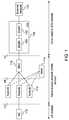
- FIG. 1illustrates an example of a cellular communication system according to embodiments of the invention.
- the networkincludes a user equipment (UE) domain, a radio access network (RAN) domain, and a core network domain.
- the UE domainincludes user equipment 110 that communicate with at least one base station 112 in the RAN domain via a wireless interface.
- the RAN domainmay also include a network controller (RNC) 118 (e.g., radio network controller), such as that used in UMTS systems. Alternatively, such functionality may be distributed between the Node Bs and an access gateway (AGW) (not shown) or other controller in the core network.
- RRCradio resource manager
- FIG. 1also illustrates an optional radio resource manager (RRM) 114 .
- the RRMmay perform functions otherwise performed by the Node Bs or an AGW in some embodiments.
- the core network (CN) 116includes, in this example, a serving GPRS support node (SGSN) 120 , and a gateway GPRS support node (GGSN) 122 .
- the core networkis coupled to an external network 124 .
- the SGSN 120is responsible for session control, including keeping track of the location of the UEs.
- the GGSN 122concentrates and tunnels user data within the core network 116 to the ultimate destination (e.g., an Internet service provider) in the external network 124 .
- 3GPP UMTS technical specificationssuch as TS23.246 v6.4.0 “3rd Generation Partnership Project; Technical Specification Group Services and System Aspects; Multimedia Broadcast/Multicast Service (MBMS); Architecture and Functional Description (Release 6),” published by the 3GPP Support Office, 650 Route des Lucioles—Sophia Antipolis, Valbonne—FRANCE, which are incorporated by reference herein.
- a system designed for operation in Time Division Duplex (TDD) modehas base stations and terminals that transmit and receive at orthogonal points in time.
- terminalsare in receive mode when the base station is transmitting, and base stations are in receive mode when terminals are transmitting.
- base stations nor the terminalsare able to transmit and receive at the same points in time because the same frequency is used for uplink and downlink communication.
- Such a systemcan be adjusted to operate in Frequency Division Duplex (FDD) mode, where the uplink and downlink communications occur on different frequencies.
- FDDFrequency Division Duplex
- the base stationsare adapted to transmit and receive at the same time. This is possible since the uplink and downlink communications now occur on different frequencies.
- the terminalsretain the restriction of transmitting and receiving at orthogonal points in time to retain the simplicity of not having to transmit and receive at the same time (e.g., no duplexer required).
- the full use of the frequency spectrumis then obtained by allocating the resource across a plurality of terminals.
- Additional measuresmay be needed if there are aspects of the air interface that rely on the channel reciprocity that can be assumed for TDD systems.
- modificationsmay be made for the correct operation of uplink power control and rate adaptation. This can be achieved by defining an uplink physical control channel used for estimating the uplink channel conditions and a downlink channel used to feed back control information to the terminal. These channels may not need an associated data physical channel to be operational.
- Modificationsmay be made to the random access channel. This may be achieved by introducing an additional indicator step at the start of any physical random access.
- a new uplink physical channelcarries the random access indicators.
- a new downlink physical channelcarries the response to received uplink indicators.
- the uplink physical control signalis referred to herein as an “Uplink Beacon” (UL_Beacon).
- a system that supports shared channelsmay also support shared access to a large number of terminals.
- shared channelscan be quickly and efficiently re-allocated between the population of UEs.
- terminalscan transmit at the correct power with their first transmission so that latency can be kept to a minimum.
- the RNC or other controller(e.g., other controller having its functionality in the core network) allocates resources so that the physical channel control signal is separate from the uplink (shared) physical channel.
- terminalsare able to transmit an UL_Beacon independently of their access to the uplink shared channel.
- the systemmay implement a closed loop control system, in which the base station detects the received power and/or other channel information from the UL_Beacon, and sends controlling commands back to each terminal to keep the terminal informed of the channel conditions observed at the base station.
- the closed loop control systemis simply based on the UL_Beacon power received at the base station.
- the base stationmay send power control commands on a shared downlink channel to each terminal based on the power received from the UL_Beacon signal.
- Each power control commandmay, for example, indicate whether terminal power should be increased or decreased by a predetermined amount.
- This downlink channelis referred to as the “Physical Layer Control Channel” (PLCCH).
- PLCCHPhysical Layer Control Channel
- the capacity of the PLCCHmay be matched to the number of bits required in the feedback field and the number of UL_Beacon signals that can be simultaneously supported. That is, each UL_Beacon may correspond to one bit of the PLLCH. All terminals transmitting UL_Beacon signals may receive this channel and extract the relevant feedback field.
- control loopit is possible to extend the complexity of the control loop by sending control commands based on other aspects of the UL_Beacon signal as received by the base station, such as time-of-arrival, and channel impulse response.
- the amount of resource that is required for the feedback channelincreases with the size (in bits) of the feedback information to each UE.
- the TDMA frame structurefor air interface technologies with a TDMA element, it is possible to adapt the TDMA frame structure to provide separation between the UL_Beacon and the normal physical channels by dedicating at least one uplink time slot per frame (or at least one time slot per multi-frame) to carrying UL_Beacon signals.
- a dedicated detection schemeBy placing UL_Beacon signals in a dedicated timeslot, a dedicated detection scheme can be applied which may include performance enhancing features such as intra-cell cancelling (for alleviating the effects of cross-correlation interference between UL_Beacon signals transmitted by multiple terminals in the same cell), or inter-cell cancelling (for reducing the interference from neighboring cells in the case where the UL_Beacon timeslots are time synchronized). Cross-interference between UL_Beacon and normal uplink bursts is avoided by the separation obtained from the use of separate time slots.
- performance enhancing featuressuch as intra-cell cancelling (for alleviating the effects of cross-correlation interference between UL_Beacon signals transmitted by multiple terminals in the same cell), or inter-cell cancelling (for reducing the interference from neighboring cells in the case where the UL_Beacon timeslots are time synchronized).
- Cross-interference between UL_Beacon and normal uplink burstsis avoided by the separation obtained from the use of
- the RNC or other controllermay allocate the UL_Beacon timeslot in a given frame to a group of terminals depending on the current fractionation phase, thus increasing the number of terminals that can be supported with active physical channel feedback control.
- the maximum fractionation cycle lengthmay be determined by the feedback update rate that the system requires in order to meet its performance targets.
- FIG. 2illustrates an example of a timeslot arrangement supporting the UL_Beacon and its corresponding PLCCH within a TD-CDMA frame structure modified to support FDD.
- the PLCCH 212shares a timeslot with another downlink shared channel. This is possible since normal downlink physical channels are used to transmit the PLCCH.
- the downlink framealso comprises a downlink beacon timeslot 206 , an access control timeslot 208 , and normal traffic carrying timeslots 210 .
- the uplink framecomprises a UL_Beacon control timeslot 216 , an access control timeslot 218 , and normal traffic carrying timeslots 214 .
- FIG. 3illustrates an example where fractionation is employed.
- the UL-Beacon and PLCCH timeslotsare active in every frame at the base station 302 .
- terminal 304 , terminal 306 , and terminal 308have been assigned a different fractionation phase.
- FIG. 3illustrates the case where the fractionation phase is 3.
- the fractionation phase of terminal 304occurs in frame #O 310
- the fractionation phase of terminal 306occurs in frame # 1 312
- the fractionation phase of terminal 308occurs in frame # 2 314 . Since the fractionation phase is 3, the phase for terminal 304 occurs again in frame # 3 316 .
- Embodiments of the inventionenable terminals to operate in half duplex or full duplex mode.
- base stations and terminalsdo not transmit and receive simultaneously.
- half duplex terminalsmay be operated with a fractionation cycle of greater than one. In particular, this may also apply for the case where there are more than one UL_Beacon timeslot per, frame. There is a time delay for half duplex terminals to switch between transmit and receive functions. In some cases this delay exceeds the guard period inserted between consecutive timeslots. In the half duplex terminal case, the terminal is unable to transmit and receive on adjacent timeslots. This will affect the locations of the UL_Beacon, PLCCH, and other common channels. Accordingly, the timeslot arrangement may be adjusted when the system is configured.
- Embodiments of this inventionseparate uplink control from the uplink physical traffic. This allows the control feedback to operate even when the terminal does not have data to send, with the consequence that uplink shared channels can be used with maximum efficiency.
- the network resources required to support the control feedback channels for these terminalsneed to be minimized.
- the number of users that can be supported with active control feedback channelsis smaller than the typical number of users per cell. Therefore, the terminals in this active state may be managed.
- UTRA RRC-ControlUniversal Terrestrial Radio Access-Radio Resource Control-Connected sub-state into the system.
- UTRA systemsalready support the idea of different RRC-Connected states (see, TS25.331 Radio Resource Control (RRC) Protocol Specification, which is incorporated herein by reference), e.g., CELL_DCH, CELL_FACH etc.
- RRCRadio Resource Control
- This sub-stateis referred to as the CELL_ACTIVE state.
- FIG. 4illustrates this sub-state in context with other UTRA RRC-connected states.
- a UE in a Cell_Active sub-statetransmits the physical channel control part of the uplink physical channel only, and nothing else (i.e., no data).
- CELL_ACTIVE sub-stateis a sub-state of CELL_FACH state 404 .
- UEs in CELL_FACH statehave an RRC connection, but they may not be actively transferring data.
- Out of the population of UEs in CELL_FACH state 404a smaller number of UEs, determined by the network to be the most-active UEs, are supported in a CELL_ACTIVE state 406 .
- the UEstransmit the physical channel control signal and listen to the associated feedback channel from the network. Because the UE is aware of the uplink pathloss conditions from the feedback channel, it can have instant access to the uplink shared channels, and the resource allocator (controller) in the network can treat the UE accordingly.
- the rules governing which UEs are maintained in CELL_ACTIVE stateare decided by the network (e.g., through the RNC) and may be based on factors such as the volume of data transfer required by the UE, the data transfer rate required by a UE, the frequency of short bursts of data transfer, the total number of UEs in CELL_FACH state, the time since the last data transfer, the UE power saving requirements, etc.
- UEs in CELL_ACTIVE statehave their transmitters active, therefore it is necessary for these UEs to monitor the status of the downlink and automatically come out of CELL_ACTIVE state if the downlink is deemed to be out-of-synchronization (for example, very high downlink errors or low received signal strength). This feature prevents UEs continuing to transmit in a state where the feedback channel may be unreliable and thus causing interference.
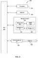
- FIG. 5illustrates a typical computing system 500 that may be employed to implement processing functionality in embodiments of the invention.
- Computing systems of this typemay be used in the radio controllers, the base stations, and the UEs, for example.
- Computing system 500may represent, for example, a desktop, laptop, or notebook computer, hand-held computing device (PDA, cell phone, palmtop, etc.), mainframe, server, client, or any other type of special or general purpose computing device as may be desirable or appropriate for a given application or environment.
- Computing system 500can include one or more processors, such as a processor 504 .
- Processor 504can be implemented using a general or special purpose processing engine such as, for example, a microprocessor, microcontroller or other control logic.
- processor 504is connected to a bus 502 or other communications medium.
- Computing system 500can also include a main memory 508 , such as random access memory (RAM) or other dynamic memory, for storing information and instructions to be executed by processor 504 .
- Main memory 508also may be used for storing temporary variables or other intermediate information during execution of instructions to be executed by processor 504 .
- Computing system 500may likewise include a read only memory (“ROM”) or other static storage device coupled to bus 502 for storing static information and instructions for processor 504 .
- ROMread only memory
- the computing system 500may also include information storage system 510 , which may include, for example, a media drive 512 and a removable storage interface 520 .
- the media drive 512may include a drive or other mechanism to support fixed or removable storage media, such as a hard disk drive, a floppy disk drive, a magnetic tape drive, an optical disk drive, a CD or DVD drive (R or RW), or other removable or fixed media drive.
- Storage media 518may include, for example, a hard disk, floppy disk, magnetic tape, optical disk, CD or DVD, or other fixed or removable medium that is read by and written to by media drive 512 .
- the storage media 518may include a computer-readable storage medium having stored therein particular computer software or data.
- information storage system 510may include other similar components for allowing computer programs or other instructions or data to be loaded into computing system 500 .
- Such componentsmay include, for example, a removable storage unit 522 and an interface 520 , such as a program cartridge and cartridge interface, a removable memory (for example, a flash memory or other removable memory module) and memory slot, and other removable storage units 522 and interfaces 520 that u allow software and data to be transferred from the removable storage unit 522 to computing system 500 .
- Computing system 500can also include a communications interface 524 .
- Communications interface 524can be used to allow software and data to be transferred between computing system 500 and external devices.
- Examples of communications interface 524can include a modem, a network interface (such as an Ethernet or other NIC card), a communications port (such as for example, a USB port), a PCMCIA slot and card, etc.
- Software and data transferred via communications interface 524are in the form of signals which can be electronic, electromagnetic, optical or other signals capable of being received by communications interface 524 . These signals are provided to communications interface 524 via a channel 528 .
- This channel 528may carry signals and may be implemented using a wireless medium, wire or cable, fiber optics, or other communications medium.
- Some examples of a channelinclude a phone line, a cellular phone link, an RF link, a network interface, a local or wide area network, and other communications channels.
- computer program productmay be used generally to refer to media such as, for example, memory 508 , storage device 518 , or storage unit 522 .
- These and other forms of computer-readable mediamay store one or more instructions for use by processor 504 , to cause the processor to perform specified operations.
- Such instructionsgenerally referred to as “computer program code” (which may be grouped in the form of computer programs or other groupings), when executed, enable the computing system 500 to perform functions of embodiments of the present invention.
- the codemay directly cause the processor to perform specified operations, be compiled to do so, and/or be combined with other software, hardware, and/or firmware elements (e.g., libraries for performing standard functions) to do so.
- the softwaremay be stored in a computer-readable medium and loaded into computing system 500 using, for example, removable storage drive 522 , drive 512 or communications interface 524 .
- the control logicin this example, software instructions or computer program code, when executed by the processor 504 , causes the processor 504 to perform the functions of the invention as described herein.
Landscapes
- Engineering & Computer Science (AREA)
- Signal Processing (AREA)
- Computer Networks & Wireless Communication (AREA)
- Mobile Radio Communication Systems (AREA)
- Bidirectional Digital Transmission (AREA)
- Time-Division Multiplex Systems (AREA)
Abstract
Description
Claims (46)
Priority Applications (9)
| Application Number | Priority Date | Filing Date | Title |
|---|---|---|---|
| US13/176,298US8811356B2 (en) | 2006-12-27 | 2011-07-05 | Communications in a wireless network |
| US14/458,693US11044010B2 (en) | 2006-12-27 | 2014-08-13 | Communications in a wireless network |
| US16/682,854US11032000B2 (en) | 2006-12-27 | 2019-11-13 | Communications in a wireless network |
| US17/339,550US11239908B2 (en) | 2006-12-27 | 2021-06-04 | Communications in a wireless network |
| US17/583,369US11411642B2 (en) | 2006-12-27 | 2022-01-25 | Communications in a wireless network |
| US17/870,425US11664889B2 (en) | 2006-12-27 | 2022-07-21 | Communications in a wireless network |
| US18/202,100US11870545B2 (en) | 2006-12-27 | 2023-05-25 | Communications in a wireless network |
| US18/400,711US12149334B2 (en) | 2006-12-27 | 2023-12-29 | Communications in a wireless network |
| US18/951,141US20250080217A1 (en) | 2006-12-27 | 2024-11-18 | Communications in a wireless network |
Applications Claiming Priority (2)
| Application Number | Priority Date | Filing Date | Title |
|---|---|---|---|
| US11/646,692US8009639B2 (en) | 2006-12-27 | 2006-12-27 | Feedback control in an FDD TDD-CDMA system |
| US13/176,298US8811356B2 (en) | 2006-12-27 | 2011-07-05 | Communications in a wireless network |
Related Parent Applications (1)
| Application Number | Title | Priority Date | Filing Date |
|---|---|---|---|
| US11/646,692ContinuationUS8009639B2 (en) | 2006-12-27 | 2006-12-27 | Feedback control in an FDD TDD-CDMA system |
Related Child Applications (1)
| Application Number | Title | Priority Date | Filing Date |
|---|---|---|---|
| US14/458,693ContinuationUS11044010B2 (en) | 2006-12-27 | 2014-08-13 | Communications in a wireless network |
Publications (2)
| Publication Number | Publication Date |
|---|---|
| US20110280165A1 US20110280165A1 (en) | 2011-11-17 |
| US8811356B2true US8811356B2 (en) | 2014-08-19 |
Family
ID=39370998
Family Applications (10)
| Application Number | Title | Priority Date | Filing Date |
|---|---|---|---|
| US11/646,692Active2028-01-29US8009639B2 (en) | 2006-12-27 | 2006-12-27 | Feedback control in an FDD TDD-CDMA system |
| US13/176,298Active2027-06-17US8811356B2 (en) | 2006-12-27 | 2011-07-05 | Communications in a wireless network |
| US14/458,693Active2028-04-02US11044010B2 (en) | 2006-12-27 | 2014-08-13 | Communications in a wireless network |
| US16/682,854ActiveUS11032000B2 (en) | 2006-12-27 | 2019-11-13 | Communications in a wireless network |
| US17/339,550ActiveUS11239908B2 (en) | 2006-12-27 | 2021-06-04 | Communications in a wireless network |
| US17/583,369ActiveUS11411642B2 (en) | 2006-12-27 | 2022-01-25 | Communications in a wireless network |
| US17/870,425ActiveUS11664889B2 (en) | 2006-12-27 | 2022-07-21 | Communications in a wireless network |
| US18/202,100ActiveUS11870545B2 (en) | 2006-12-27 | 2023-05-25 | Communications in a wireless network |
| US18/400,711ActiveUS12149334B2 (en) | 2006-12-27 | 2023-12-29 | Communications in a wireless network |
| US18/951,141PendingUS20250080217A1 (en) | 2006-12-27 | 2024-11-18 | Communications in a wireless network |
Family Applications Before (1)
| Application Number | Title | Priority Date | Filing Date |
|---|---|---|---|
| US11/646,692Active2028-01-29US8009639B2 (en) | 2006-12-27 | 2006-12-27 | Feedback control in an FDD TDD-CDMA system |
Family Applications After (8)
| Application Number | Title | Priority Date | Filing Date |
|---|---|---|---|
| US14/458,693Active2028-04-02US11044010B2 (en) | 2006-12-27 | 2014-08-13 | Communications in a wireless network |
| US16/682,854ActiveUS11032000B2 (en) | 2006-12-27 | 2019-11-13 | Communications in a wireless network |
| US17/339,550ActiveUS11239908B2 (en) | 2006-12-27 | 2021-06-04 | Communications in a wireless network |
| US17/583,369ActiveUS11411642B2 (en) | 2006-12-27 | 2022-01-25 | Communications in a wireless network |
| US17/870,425ActiveUS11664889B2 (en) | 2006-12-27 | 2022-07-21 | Communications in a wireless network |
| US18/202,100ActiveUS11870545B2 (en) | 2006-12-27 | 2023-05-25 | Communications in a wireless network |
| US18/400,711ActiveUS12149334B2 (en) | 2006-12-27 | 2023-12-29 | Communications in a wireless network |
| US18/951,141PendingUS20250080217A1 (en) | 2006-12-27 | 2024-11-18 | Communications in a wireless network |
Country Status (6)
| Country | Link |
|---|---|
| US (10) | US8009639B2 (en) |
| EP (2) | EP3541134B1 (en) |
| JP (1) | JP5393477B2 (en) |
| KR (1) | KR101379101B1 (en) |
| CN (1) | CN101595760B (en) |
| WO (1) | WO2008077951A1 (en) |
Cited By (1)
| Publication number | Priority date | Publication date | Assignee | Title |
|---|---|---|---|---|
| US12402231B1 (en) | 2025-01-29 | 2025-08-26 | Visionary Technologies Limited | Systems and methods for creating device networks |
Families Citing this family (12)
| Publication number | Priority date | Publication date | Assignee | Title |
|---|---|---|---|---|
| US8009639B2 (en) | 2006-12-27 | 2011-08-30 | Wireless Technology Solutions Llc | Feedback control in an FDD TDD-CDMA system |
| US20090203323A1 (en)* | 2008-02-13 | 2009-08-13 | Motorola, Inc. | Uplink control signaling in a communication system |
| KR101467782B1 (en)* | 2008-02-25 | 2014-12-03 | 엘지전자 주식회사 | Coexistence support method in mobile terminal |
| KR101490245B1 (en) | 2008-02-25 | 2015-02-05 | 엘지전자 주식회사 | Coexistence Support Method Considering Subchannel Allocation of Broadband Wireless Access System |
| KR101467783B1 (en)* | 2008-02-25 | 2014-12-03 | 엘지전자 주식회사 | How to Support Coexistence with Wireless Personal Area Network |
| US8861443B2 (en)* | 2012-09-20 | 2014-10-14 | Intel Corporation | Method and apparatus for power control in full-duplex wireless systems with simultaneous transmission reception |
| CN105981463B (en) | 2014-02-16 | 2019-12-10 | Lg电子株式会社 | Resource allocation method and device in wireless access system supporting FDR transmission |
| US10367633B2 (en)* | 2015-04-15 | 2019-07-30 | Nokia Technologies Oy | Wireless communication |
| CN107231680B (en)* | 2016-03-23 | 2021-04-30 | 中兴通讯股份有限公司 | Method and device for open-loop power control |
| CN106535342B (en)* | 2016-11-30 | 2019-04-02 | 北京大学 | Resource allocation methods for Full-duplex cellular network safety of physical layer scene |
| WO2018177548A1 (en)* | 2017-03-31 | 2018-10-04 | Huawei Technologies Co., Ltd. | Radio system with uplink beacon transmission |
| US11659531B2 (en)* | 2020-04-22 | 2023-05-23 | Qualcomm Incorporated | Signaling to adjust slot format in a wireless communication system |
Citations (31)
| Publication number | Priority date | Publication date | Assignee | Title |
|---|---|---|---|---|
| US5056109A (en) | 1989-11-07 | 1991-10-08 | Qualcomm, Inc. | Method and apparatus for controlling transmission power in a cdma cellular mobile telephone system |
| US5265119A (en) | 1989-11-07 | 1993-11-23 | Qualcomm Incorporated | Method and apparatus for controlling transmission power in a CDMA cellular mobile telephone system |
| US5485486A (en) | 1989-11-07 | 1996-01-16 | Qualcomm Incorporated | Method and apparatus for controlling transmission power in a CDMA cellular mobile telephone system |
| JPH11261544A (en) | 1998-03-10 | 1999-09-24 | Matsushita Electric Ind Co Ltd | Time division duplex CDMA mobile communication system and method |
| US6061784A (en) | 1996-12-26 | 2000-05-09 | Nortel Networks Corporation | Method and device for transferring data frames within a serial stream |
| US20020061005A1 (en) | 2000-10-05 | 2002-05-23 | Samsung Electronics Co., Ltd. | TSTD apparatus and method for a TDD CDMA mobile communication system |
| US20020077151A1 (en)* | 2000-12-18 | 2002-06-20 | Gary Matthews | Polymorphic cellular network architecture |
| US20020075891A1 (en) | 2000-12-16 | 2002-06-20 | Slim Souissi | Network assisted random access method |
| DE10201270A1 (en) | 2001-01-15 | 2002-08-08 | Samsung Electronics Co Ltd | Method and device for controlling the transmission power in an NB-TDD CDMA communication system |
| US20020119798A1 (en) | 2001-02-28 | 2002-08-29 | Nec Corporation | Mobile communication system, transmission power control method therefor, and base station used therefor |
| US20020150058A1 (en)* | 2000-11-02 | 2002-10-17 | Samsung Electronics Co., Ltd. | Apparatus and method for randomly controlling time slot of sub-frame in an NB-TDD CDMA system |
| US20020168993A1 (en) | 2001-05-10 | 2002-11-14 | Koninklijke Philips Electronics N.V. | Updating path loss estimation for power control and link adaptation in IEEE 802.11h WLAN |
| US20030022683A1 (en)* | 2001-07-04 | 2003-01-30 | Mark Beckmann | Method for transmitting multicast messages in a radio system, and correspondingly designed radio system, transmitter and receiver |
| US20030069020A1 (en)* | 2001-07-06 | 2003-04-10 | Ipwireless, Inc. | System and method for physical shared channel allocation in a wireless communication system |
| US6567459B1 (en) | 1997-05-16 | 2003-05-20 | Nokia Corporation | Power control in mobile communications system |
| US20040152473A1 (en) | 2003-01-10 | 2004-08-05 | Nec Corporation | Mobile communication system, radio network controller, radio terminal, data delivering method, and program for the method |
| EP1467582A1 (en) | 2003-04-11 | 2004-10-13 | Telefonaktiebolaget LM Ericsson (publ) | Method for synchronization in a mobile radio terminal |
| US20040203419A1 (en) | 2002-04-08 | 2004-10-14 | Crocker Ronald T. | System and method for predictive transmit power control for mobile stations in a multiple access wireless communication system |
| EP1615384A1 (en) | 2002-10-25 | 2006-01-11 | QUALCOMM Incorporated | Mimo wlan system |
| WO2006019263A2 (en) | 2004-08-17 | 2006-02-23 | Lg Electronics Inc. | A method for establishing fast feedback channel and transmitting information in a wireless communication system |
| US20060093026A1 (en) | 2004-09-24 | 2006-05-04 | Juan Montojo | Method and system for power control in a communication system |
| WO2006063138A2 (en) | 2004-12-07 | 2006-06-15 | Adaptix, Inc. | Cooperative mimo in multicell wireless networks |
| EP1681780A1 (en) | 2005-01-14 | 2006-07-19 | Fujitsu Limited | Mobile wireless communication system and wireless communication apparatus |
| US20060211417A1 (en) | 2003-05-08 | 2006-09-21 | Pedlar David W | Apparatus and method of uplink data during cell update in universal mobile telecommunications system user equipment |
| US7120134B2 (en) | 2001-02-15 | 2006-10-10 | Qualcomm, Incorporated | Reverse link channel architecture for a wireless communication system |
| US7215657B2 (en) | 2000-04-21 | 2007-05-08 | Kabushiki Kaisha Toshiba | Radio base station and frame configuration method using TDMA scheme and SDMA scheme |
| US20070173256A1 (en) | 2003-12-05 | 2007-07-26 | Rajiv Laroia | Methods and apparatus for performing handoffs in a multi-carrier wireless communications system |
| US20070265017A1 (en)* | 2005-11-30 | 2007-11-15 | Ntt Docomo, Inc. | Call admission control device and call admission control method |
| US20080090528A1 (en)* | 2006-07-07 | 2008-04-17 | Malladi Durga P | Method and apparatus for sending data and control information in a wireless communication system |
| US20080144600A1 (en)* | 2004-08-13 | 2008-06-19 | Ipwireless, Inc. | Apparatus and Method for Communicating User Equipment Specific Information in Cellular Communication System |
| US8009639B2 (en) | 2006-12-27 | 2011-08-30 | Wireless Technology Solutions Llc | Feedback control in an FDD TDD-CDMA system |
Family Cites Families (27)
| Publication number | Priority date | Publication date | Assignee | Title |
|---|---|---|---|---|
| JPH10173594A (en)* | 1996-12-06 | 1998-06-26 | Hitachi Ltd | Code division multiple access communication system and transmission power control method |
| DE69935715T2 (en)* | 1999-01-16 | 2007-12-27 | Koninklijke Philips Electronics N.V. | RADIO COMMUNICATION SYSTEM |
| CN1132391C (en)* | 1999-08-09 | 2003-12-24 | 华为技术有限公司 | Pilot-type synchronous channel structure for mobile communication system |
| DE19956492A1 (en)* | 1999-11-24 | 2001-05-31 | Siemens Ag | Format identification (TFCI) bits display method for compressed mode frame transmission esp. in UMTS mobile radio standard |
| AU760513B2 (en) | 2000-02-16 | 2003-05-15 | Samsung Electronics Co., Ltd. | Apparatus and method for assigning a common packet channel in a CDMA communication system |
| SG96568A1 (en)* | 2000-09-21 | 2003-06-16 | Univ Singapore | Beam synthesis method for downlink beamforming in fdd wireless communication system. |
| CN1964229B (en)* | 2000-10-24 | 2012-09-26 | 北方电讯网络有限公司 | Shared channel structure, systems and methods |
| DE10056258B4 (en)* | 2000-11-14 | 2004-02-26 | Rohde & Schwarz Gmbh & Co. Kg | Method for determining and displaying the power components of the codes of a CDMA signal |
| US7010318B2 (en)* | 2001-01-13 | 2006-03-07 | Samsung Electronics Co., Ltd. | Power control apparatus and method for a W-CDMA communication system employing a high-speed downlink packet access scheme |
| TW520587B (en) | 2001-01-13 | 2003-02-11 | Koninkl Philips Electronics Nv | Radio communication system |
| US20020114311A1 (en)* | 2001-02-16 | 2002-08-22 | Sara Mazur | Continuous allocation of real-time traffic in a telecommunication system |
| US7310336B2 (en)* | 2001-05-18 | 2007-12-18 | Esa Malkamaki | Hybrid automatic repeat request (HARQ) scheme with in-sequence delivery of packets |
| EP1274178A1 (en)* | 2001-06-28 | 2003-01-08 | Siemens Information and Communication Networks S.p.A. | Downlink power control in packet switching cellular systems with dynamic channel allocation |
| CA2354196A1 (en)* | 2001-07-26 | 2003-01-26 | Shiquan Wu | Method of and apparatus for communication via multiplexed links |
| CN1476716A (en)* | 2001-10-03 | 2004-02-18 | ��ʽ����Ntt����Ħ | Relay terminal, base station, billing server, communication system, billing method, program, computer data signal, and storage medium |
| US7453847B2 (en)* | 2001-10-19 | 2008-11-18 | Telefonaktiebolaget L M Ericsson (Publ) | Method and arrangement for channel type switching |
| US6901063B2 (en)* | 2002-05-13 | 2005-05-31 | Qualcomm, Incorporated | Data delivery in conjunction with a hybrid automatic retransmission mechanism in CDMA communication systems |
| KR20030092894A (en) | 2002-05-31 | 2003-12-06 | 삼성전자주식회사 | Apparatus for determining report period of channel quality in communication system using high speed data packet access scheme and method thereof |
| US7986742B2 (en)* | 2002-10-25 | 2011-07-26 | Qualcomm Incorporated | Pilots for MIMO communication system |
| US7372898B2 (en) | 2002-12-11 | 2008-05-13 | Interdigital Technology Corporation | Path loss measurements in wireless communications |
| EP1496622B1 (en) | 2003-07-07 | 2007-11-14 | Samsung Electronics Co., Ltd. | Method and apparatus for detecting active downlink channelization codes in a TD-CDMA mobile communication system |
| CN1926778A (en)* | 2004-02-27 | 2007-03-07 | 日本电气株式会社 | CDMA receiving apparatus and method |
| KR101071816B1 (en)* | 2004-04-02 | 2011-10-11 | 엘지전자 주식회사 | Method of scheduling of uplink packet in mobile packet communication system |
| JP2005346319A (en)* | 2004-06-02 | 2005-12-15 | Hitachi Ltd | Design development / procurement instruction management system and management method |
| US7821913B2 (en)* | 2005-03-29 | 2010-10-26 | Qualcomm Incorporated | Method and apparatus for data and pilot structures supporting equalization |
| US20070058595A1 (en) | 2005-03-30 | 2007-03-15 | Motorola, Inc. | Method and apparatus for reducing round trip latency and overhead within a communication system |
| JP4567628B2 (en)* | 2005-06-14 | 2010-10-20 | 株式会社エヌ・ティ・ティ・ドコモ | Mobile station, transmission method and communication system |
- 2006
- 2006-12-27USUS11/646,692patent/US8009639B2/enactiveActive
- 2007
- 2007-12-21WOPCT/EP2007/064483patent/WO2008077951A1/enactiveApplication Filing
- 2007-12-21KRKR1020097015635Apatent/KR101379101B1/enactiveActive
- 2007-12-21JPJP2009543459Apatent/JP5393477B2/enactiveActive
- 2007-12-21CNCN2007800506399Apatent/CN101595760B/enactiveActive
- 2007-12-21EPEP19151934.7Apatent/EP3541134B1/enactiveActive
- 2007-12-21EPEP07858094.1Apatent/EP2103157B1/enactiveActive
- 2011
- 2011-07-05USUS13/176,298patent/US8811356B2/enactiveActive
- 2014
- 2014-08-13USUS14/458,693patent/US11044010B2/enactiveActive
- 2019
- 2019-11-13USUS16/682,854patent/US11032000B2/enactiveActive
- 2021
- 2021-06-04USUS17/339,550patent/US11239908B2/enactiveActive
- 2022
- 2022-01-25USUS17/583,369patent/US11411642B2/enactiveActive
- 2022-07-21USUS17/870,425patent/US11664889B2/enactiveActive
- 2023
- 2023-05-25USUS18/202,100patent/US11870545B2/enactiveActive
- 2023-12-29USUS18/400,711patent/US12149334B2/enactiveActive
- 2024
- 2024-11-18USUS18/951,141patent/US20250080217A1/enactivePending
Patent Citations (36)
| Publication number | Priority date | Publication date | Assignee | Title |
|---|---|---|---|---|
| US5265119A (en) | 1989-11-07 | 1993-11-23 | Qualcomm Incorporated | Method and apparatus for controlling transmission power in a CDMA cellular mobile telephone system |
| US5485486A (en) | 1989-11-07 | 1996-01-16 | Qualcomm Incorporated | Method and apparatus for controlling transmission power in a CDMA cellular mobile telephone system |
| US5056109A (en) | 1989-11-07 | 1991-10-08 | Qualcomm, Inc. | Method and apparatus for controlling transmission power in a cdma cellular mobile telephone system |
| US6061784A (en) | 1996-12-26 | 2000-05-09 | Nortel Networks Corporation | Method and device for transferring data frames within a serial stream |
| US6567459B1 (en) | 1997-05-16 | 2003-05-20 | Nokia Corporation | Power control in mobile communications system |
| JPH11261544A (en) | 1998-03-10 | 1999-09-24 | Matsushita Electric Ind Co Ltd | Time division duplex CDMA mobile communication system and method |
| US6611509B1 (en) | 1998-03-10 | 2003-08-26 | Matsushita Electric Industrial Co., Ltd. | CDMA/TDD mobile communication system and method |
| US7215657B2 (en) | 2000-04-21 | 2007-05-08 | Kabushiki Kaisha Toshiba | Radio base station and frame configuration method using TDMA scheme and SDMA scheme |
| US20020061005A1 (en) | 2000-10-05 | 2002-05-23 | Samsung Electronics Co., Ltd. | TSTD apparatus and method for a TDD CDMA mobile communication system |
| US20020150058A1 (en)* | 2000-11-02 | 2002-10-17 | Samsung Electronics Co., Ltd. | Apparatus and method for randomly controlling time slot of sub-frame in an NB-TDD CDMA system |
| US20020075891A1 (en) | 2000-12-16 | 2002-06-20 | Slim Souissi | Network assisted random access method |
| US20020077151A1 (en)* | 2000-12-18 | 2002-06-20 | Gary Matthews | Polymorphic cellular network architecture |
| US20020196766A1 (en) | 2001-01-15 | 2002-12-26 | Samsung Electronics Co., Ltd. | Apparatus and method for controlling transmission power in an NB-TDD CDMA communication system |
| DE10201270A1 (en) | 2001-01-15 | 2002-08-08 | Samsung Electronics Co Ltd | Method and device for controlling the transmission power in an NB-TDD CDMA communication system |
| US7120134B2 (en) | 2001-02-15 | 2006-10-10 | Qualcomm, Incorporated | Reverse link channel architecture for a wireless communication system |
| US20020119798A1 (en) | 2001-02-28 | 2002-08-29 | Nec Corporation | Mobile communication system, transmission power control method therefor, and base station used therefor |
| US20020168993A1 (en) | 2001-05-10 | 2002-11-14 | Koninklijke Philips Electronics N.V. | Updating path loss estimation for power control and link adaptation in IEEE 802.11h WLAN |
| US6978151B2 (en) | 2001-05-10 | 2005-12-20 | Koninklijke Philips Electronics N.V. | Updating path loss estimation for power control and link adaptation in IEEE 802.11h WLAN |
| US20030022683A1 (en)* | 2001-07-04 | 2003-01-30 | Mark Beckmann | Method for transmitting multicast messages in a radio system, and correspondingly designed radio system, transmitter and receiver |
| US20030069020A1 (en)* | 2001-07-06 | 2003-04-10 | Ipwireless, Inc. | System and method for physical shared channel allocation in a wireless communication system |
| US20040203419A1 (en) | 2002-04-08 | 2004-10-14 | Crocker Ronald T. | System and method for predictive transmit power control for mobile stations in a multiple access wireless communication system |
| EP1615384A1 (en) | 2002-10-25 | 2006-01-11 | QUALCOMM Incorporated | Mimo wlan system |
| US20040152473A1 (en) | 2003-01-10 | 2004-08-05 | Nec Corporation | Mobile communication system, radio network controller, radio terminal, data delivering method, and program for the method |
| EP1467582A1 (en) | 2003-04-11 | 2004-10-13 | Telefonaktiebolaget LM Ericsson (publ) | Method for synchronization in a mobile radio terminal |
| US20060211417A1 (en) | 2003-05-08 | 2006-09-21 | Pedlar David W | Apparatus and method of uplink data during cell update in universal mobile telecommunications system user equipment |
| US20070173256A1 (en) | 2003-12-05 | 2007-07-26 | Rajiv Laroia | Methods and apparatus for performing handoffs in a multi-carrier wireless communications system |
| US20080144600A1 (en)* | 2004-08-13 | 2008-06-19 | Ipwireless, Inc. | Apparatus and Method for Communicating User Equipment Specific Information in Cellular Communication System |
| WO2006019263A2 (en) | 2004-08-17 | 2006-02-23 | Lg Electronics Inc. | A method for establishing fast feedback channel and transmitting information in a wireless communication system |
| US20060093026A1 (en) | 2004-09-24 | 2006-05-04 | Juan Montojo | Method and system for power control in a communication system |
| WO2006063138A2 (en) | 2004-12-07 | 2006-06-15 | Adaptix, Inc. | Cooperative mimo in multicell wireless networks |
| EP1681780A1 (en) | 2005-01-14 | 2006-07-19 | Fujitsu Limited | Mobile wireless communication system and wireless communication apparatus |
| JP2006197318A (en) | 2005-01-14 | 2006-07-27 | Fujitsu Ltd | Mobile radio communication system and radio communication apparatus |
| US8072916B2 (en) | 2005-01-14 | 2011-12-06 | Fujitsu Limited | Mobile wireless communication system and wireless communication apparatus using transmission power control information |
| US20070265017A1 (en)* | 2005-11-30 | 2007-11-15 | Ntt Docomo, Inc. | Call admission control device and call admission control method |
| US20080090528A1 (en)* | 2006-07-07 | 2008-04-17 | Malladi Durga P | Method and apparatus for sending data and control information in a wireless communication system |
| US8009639B2 (en) | 2006-12-27 | 2011-08-30 | Wireless Technology Solutions Llc | Feedback control in an FDD TDD-CDMA system |
Non-Patent Citations (20)
| Title |
|---|
| "3 UMTS Interfaces," UMTS Protocols and Protocol Testing, pp. 9-14, located at . |
| "3 UMTS Interfaces," UMTS Protocols and Protocol Testing, pp. 9-14, located at <http://www.tek.com/Measurement/App.sub.--Notes/2F.sub.--14251/eng/int- erfaces.pdf>. |
| "3rd Generation Partnership Project; Technical Specification Group Radio Access Network; Feasibility Study for Evolved UTRA and UTRAN (Release 7)," (Mar. 2006). 3GPP:Valbonne, France, TS 25.912 v0.0.4:1-13. |
| "3rd Generation Partnership Project; Technical Specification Group Services and System Aspects; 3GPP System Architecture Evolution: Report on Technical Options and Conclusions (Release 7)," (Jul. 2005). 3GPP:Valbonne, France, TS 23.882 v0.3.0:1-13. |
| "3rd Generation Partnership Project; Technical Specification Group Services and System Aspects; General UMTS Architecture (3G TS23.101 version 3.0.1)," (Apr. 1999). 3GPP:Valbonne, France, TS 23.101 v3.0.1:1-13. |
| "UMTS Protocols and Protocol Testing," Tektronix, The International Engineering Consortium, pp. 1-45, located at . |
| "UMTS Protocols and Protocol Testing," Tektronix, The International Engineering Consortium, pp. 1-45, located at <http://www.rfpeople.com/docs/umts.pdf>. |
| 3rd Generation Partnership Project, "Technical Specification Group Radio Access Network; Radio Resource Control (RRC); Protocol Specification (Release 7)," 3GPP TS 25.331 V7.3.0, Dec. 2006. |
| 3rd Generation Partnership Project; Technical Specification Group Services and System Aspects; Multimedia Broadcast/Multicast Service (MBMS); Architecture and Functional Description (Release 6); 3GPP: Valbonne, France; 3GPP TS 23.246 v.6.4.0 (Sep. 2004). |
| Final Rejection issued by USPTO, dated Nov. 19, 2009 for U.S. Appl. No. 11/646,692. |
| Ghadialy, Z. "Tutorial: Medium Access Control (MAC) in 3G/UMTS Protocol Stack," located at <http://www.3g4g.co.uk/Tutorial/ZG/zg.sub.--mac.html> visited on Jun. 20, 2007. (9 pages). |
| Ghadialy, Z. "Tutorial: Medium Access Control (MAC) in 3G/UMTS Protocol Stack," located at visited on Jun. 20, 2007. (9 pages). |
| International Engineering Consortium. "Universal Mobile Telecommunications System (UMTS) Protocols and Protocol Testing," located at <http://www.iec.org/online/tutorials/umts/topic02.html> visited on Jun. 20, 2007. (7 pages). |
| International Engineering Consortium. "Universal Mobile Telecommunications System (UMTS) Protocols and Protocol Testing," located at visited on Jun. 20, 2007. (7 pages). |
| International Preliminary Report on Patentability issued on Jun. 30, 2009 from PCT Application No. PCT/EP20071064483. |
| Non-Final Rejection issued by USPTO, dated May 14, 2009 for U.S. Appl. No. 11/646,692. |
| Non-Final Rejection issued by USPTO, dated May 28, 2010 for U.S. Appl. No. 11/646,692. |
| Notice of Allowance issued by USPTO, dated Feb. 2, 2011 for U.S. Appl. No. 11/646,692. |
| Notice of Allowance issued by USPTO, dated May 17, 2011 for U.S. Appl. No. 11/646,692. |
| Office Action, Japanese Patent Application No. 2009-543459, dated Dec. 18, 2012. |
Cited By (1)
| Publication number | Priority date | Publication date | Assignee | Title |
|---|---|---|---|---|
| US12402231B1 (en) | 2025-01-29 | 2025-08-26 | Visionary Technologies Limited | Systems and methods for creating device networks |
Also Published As
| Publication number | Publication date |
|---|---|
| US20110280165A1 (en) | 2011-11-17 |
| US8009639B2 (en) | 2011-08-30 |
| KR101379101B1 (en) | 2014-03-31 |
| US20140348041A1 (en) | 2014-11-27 |
| JP2010515323A (en) | 2010-05-06 |
| US20240137116A1 (en) | 2024-04-25 |
| CN101595760A (en) | 2009-12-02 |
| EP3541134A1 (en) | 2019-09-18 |
| US11032000B2 (en) | 2021-06-08 |
| US20210298003A1 (en) | 2021-09-23 |
| US12149334B2 (en) | 2024-11-19 |
| US20200083952A1 (en) | 2020-03-12 |
| US11239908B2 (en) | 2022-02-01 |
| EP2103157A1 (en) | 2009-09-23 |
| JP5393477B2 (en) | 2014-01-22 |
| US20230299846A1 (en) | 2023-09-21 |
| KR20090106552A (en) | 2009-10-09 |
| US20080159185A1 (en) | 2008-07-03 |
| US20220150840A1 (en) | 2022-05-12 |
| EP2103157B1 (en) | 2019-01-16 |
| US11870545B2 (en) | 2024-01-09 |
| EP3541134B1 (en) | 2023-06-07 |
| CN101595760B (en) | 2013-01-23 |
| US11664889B2 (en) | 2023-05-30 |
| US11044010B2 (en) | 2021-06-22 |
| WO2008077951A1 (en) | 2008-07-03 |
| US20220360325A1 (en) | 2022-11-10 |
| US11411642B2 (en) | 2022-08-09 |
| US20250080217A1 (en) | 2025-03-06 |
Similar Documents
| Publication | Publication Date | Title |
|---|---|---|
| US12149334B2 (en) | Communications in a wireless network | |
| JP7227679B2 (en) | Time division duplex wireless communication system | |
| CN100469168C (en) | assigning time slots during transmission gaps of first protocol communications to second protocol communications | |
| CN100551150C (en) | Adaptive control method for manipulating communication environment | |
| JP4843692B2 (en) | Power control apparatus for mobile radio communication system | |
| EP2842350A1 (en) | Switching between downlink and uplink | |
| KR20190039553A (en) | Device, base station and method for communicating a scheduling request over an underlay control channel in a wireless communication system | |
| EP3430844B1 (en) | Telegram splitting for slotted aloha | |
| WO2013014856A1 (en) | Mobile communication system, wireless base station, mobile station, data transmission method, data reception method, and computer-readable medium | |
| EP1192764B1 (en) | Method and means for transmitting and receiving packet data units in a cellular radio communication system | |
| EP4459914A1 (en) | Method and apparatus for uplink transmission in wireless communication system | |
| HK40003473B (en) | Telegram splitting for slotted aloha | |
| HK40003473A (en) | Telegram splitting for slotted aloha |
Legal Events
| Date | Code | Title | Description |
|---|---|---|---|
| AS | Assignment | Owner name:IPWIRELESS, INC., CALIFORNIA Free format text:ASSIGNMENT OF ASSIGNORS INTEREST;ASSIGNOR:WIRELESS TECHNOLOGY SOLUTIONS LLC;REEL/FRAME:027910/0649 Effective date:20120301 | |
| AS | Assignment | Owner name:WIRELESS TECHNOLOGY SOLUTIONS LLC, NEW YORK Free format text:ASSIGNMENT OF ASSIGNORS INTEREST;ASSIGNOR:IPWIRELESS, INC.;REEL/FRAME:027938/0566 Effective date:20100423 Owner name:IPWIRELESS, INC., CALIFORNIA Free format text:ASSIGNMENT OF ASSIGNORS INTEREST;ASSIGNOR:NORTHROP GRUMMAN INFORMATION TECHNOLOGY, INC.;REEL/FRAME:027938/0464 Effective date:20091103 Owner name:IPWIRELESS, INC., CALIFORNIA Free format text:ASSIGNMENT OF ASSIGNORS INTEREST;ASSIGNOR:HOWARD, PAUL;REEL/FRAME:027937/0788 Effective date:20070403 Owner name:NORTHROP GRUMMAN INFORMATION TECHNOLOGY, INC., CAL Free format text:ASSIGNMENT OF ASSIGNORS INTEREST;ASSIGNOR:IPWIRELESS, INC.;REEL/FRAME:027938/0301 Effective date:20081224 | |
| AS | Assignment | Owner name:INTELLECTUAL VENTURES HOLDING 81 LLC, NEVADA Free format text:ASSIGNMENT OF ASSIGNORS INTEREST;ASSIGNOR:IPWIRELESS, INC.;REEL/FRAME:028175/0237 Effective date:20120427 | |
| FEPP | Fee payment procedure | Free format text:PAYOR NUMBER ASSIGNED (ORIGINAL EVENT CODE: ASPN); ENTITY STATUS OF PATENT OWNER: LARGE ENTITY | |
| STCF | Information on status: patent grant | Free format text:PATENTED CASE | |
| AS | Assignment | Owner name:INTELLECTUAL VENTURES II LLC, DELAWARE Free format text:ASSIGNMENT OF ASSIGNORS INTEREST;ASSIGNOR:INTELLECTUAL VENTURES HOLDING 81 LLC;REEL/FRAME:042459/0204 Effective date:20170519 | |
| MAFP | Maintenance fee payment | Free format text:PAYMENT OF MAINTENANCE FEE, 4TH YEAR, LARGE ENTITY (ORIGINAL EVENT CODE: M1551) Year of fee payment:4 | |
| MAFP | Maintenance fee payment | Free format text:PAYMENT OF MAINTENANCE FEE, 8TH YEAR, LARGE ENTITY (ORIGINAL EVENT CODE: M1552); ENTITY STATUS OF PATENT OWNER: LARGE ENTITY Year of fee payment:8 | |
| IPR | Aia trial proceeding filed before the patent and appeal board: inter partes review | Free format text:TRIAL NO: IPR2022-01130 Opponent name:TOYOTA MOTOR CORP., TOYOTA MOTOR NORTH AMERICA, INC., TOYOTA MOTOR ENGINEERING MANUFACTURING NORTH AMERICA, INC., TOYOTA MOTOR SALES, U.S.A., INC., CONTINENTAL AUTOMOTIVE SYSTEMS, INC., CONTINENTAL AUTOMOTIVE GMBH, CONTINENTAL AUTOMOTIVE TECHNOLOGIES GMBH, CONTINENTAL AUTOMOTIVE, INC., AND CONTINENTAL AG Effective date:20220613 | |
| IPR | Aia trial proceeding filed before the patent and appeal board: inter partes review | Free format text:TRIAL NO: IPR2023-00077 Opponent name:AMERICAN HONDA MOTOR CO., INC.,HONDA MOTOR CO., LTD., ANDAMERICAN HONDA FINANCE CORP. Effective date:20221019 | |
| IPRC | Trial and appeal board: inter partes review certificate | Kind code of ref document:K1 Free format text:INTER PARTES REVIEW CERTIFICATE; TRIAL NO. IPR2022-01130, JUN. 13, 2022 INTER PARTES REVIEW CERTIFICATE FOR PATENT 8,811,356, ISSUED AUG. 19, 2014, APPL. NO. 13/176,298, JUL. 5, 2011 INTER PARTES REVIEW CERTIFICATE ISSUED APR. 2, 2024 Effective date:20240402 | |
| CC | Certificate of correction |