US8811172B1 - Network path selection using bandwidth prediction - Google Patents
Network path selection using bandwidth predictionDownload PDFInfo
- Publication number
- US8811172B1 US8811172B1US14/250,132US201414250132AUS8811172B1US 8811172 B1US8811172 B1US 8811172B1US 201414250132 AUS201414250132 AUS 201414250132AUS 8811172 B1US8811172 B1US 8811172B1
- Authority
- US
- United States
- Prior art keywords
- path
- determined
- data stream
- new data
- type
- Prior art date
- Legal status (The legal status is an assumption and is not a legal conclusion. Google has not performed a legal analysis and makes no representation as to the accuracy of the status listed.)
- Active
Links
Images


Classifications
- H—ELECTRICITY
- H04—ELECTRIC COMMUNICATION TECHNIQUE
- H04L—TRANSMISSION OF DIGITAL INFORMATION, e.g. TELEGRAPHIC COMMUNICATION
- H04L41/00—Arrangements for maintenance, administration or management of data switching networks, e.g. of packet switching networks
- H04L41/12—Discovery or management of network topologies
- H—ELECTRICITY
- H04—ELECTRIC COMMUNICATION TECHNIQUE
- H04L—TRANSMISSION OF DIGITAL INFORMATION, e.g. TELEGRAPHIC COMMUNICATION
- H04L41/00—Arrangements for maintenance, administration or management of data switching networks, e.g. of packet switching networks
- H04L41/06—Management of faults, events, alarms or notifications
- H04L41/0654—Management of faults, events, alarms or notifications using network fault recovery
- H—ELECTRICITY
- H04—ELECTRIC COMMUNICATION TECHNIQUE
- H04L—TRANSMISSION OF DIGITAL INFORMATION, e.g. TELEGRAPHIC COMMUNICATION
- H04L43/00—Arrangements for monitoring or testing data switching networks
- H04L43/08—Monitoring or testing based on specific metrics, e.g. QoS, energy consumption or environmental parameters
- H04L43/0876—Network utilisation, e.g. volume of load or congestion level
- H—ELECTRICITY
- H04—ELECTRIC COMMUNICATION TECHNIQUE
- H04L—TRANSMISSION OF DIGITAL INFORMATION, e.g. TELEGRAPHIC COMMUNICATION
- H04L45/00—Routing or path finding of packets in data switching networks
- H04L45/02—Topology update or discovery
- H04L45/025—Updating only a limited number of routers, e.g. fish-eye update
- H—ELECTRICITY
- H04—ELECTRIC COMMUNICATION TECHNIQUE
- H04L—TRANSMISSION OF DIGITAL INFORMATION, e.g. TELEGRAPHIC COMMUNICATION
- H04L45/00—Routing or path finding of packets in data switching networks
- H04L45/12—Shortest path evaluation
- H04L45/125—Shortest path evaluation based on throughput or bandwidth
- H—ELECTRICITY
- H04—ELECTRIC COMMUNICATION TECHNIQUE
- H04L—TRANSMISSION OF DIGITAL INFORMATION, e.g. TELEGRAPHIC COMMUNICATION
- H04L45/00—Routing or path finding of packets in data switching networks
- H04L45/42—Centralised routing
- H—ELECTRICITY
- H04—ELECTRIC COMMUNICATION TECHNIQUE
- H04L—TRANSMISSION OF DIGITAL INFORMATION, e.g. TELEGRAPHIC COMMUNICATION
- H04L45/00—Routing or path finding of packets in data switching networks
- H04L45/56—Routing software
- H—ELECTRICITY
- H04—ELECTRIC COMMUNICATION TECHNIQUE
- H04L—TRANSMISSION OF DIGITAL INFORMATION, e.g. TELEGRAPHIC COMMUNICATION
- H04L45/00—Routing or path finding of packets in data switching networks
- H04L45/64—Routing or path finding of packets in data switching networks using an overlay routing layer
- H—ELECTRICITY
- H04—ELECTRIC COMMUNICATION TECHNIQUE
- H04L—TRANSMISSION OF DIGITAL INFORMATION, e.g. TELEGRAPHIC COMMUNICATION
- H04L45/00—Routing or path finding of packets in data switching networks
- H04L45/645—Splitting route computation layer and forwarding layer, e.g. routing according to path computational element [PCE] or based on OpenFlow functionality
- H—ELECTRICITY
- H04—ELECTRIC COMMUNICATION TECHNIQUE
- H04L—TRANSMISSION OF DIGITAL INFORMATION, e.g. TELEGRAPHIC COMMUNICATION
- H04L45/00—Routing or path finding of packets in data switching networks
- H04L45/74—Address processing for routing
- H04L45/745—Address table lookup; Address filtering
- H—ELECTRICITY
- H04—ELECTRIC COMMUNICATION TECHNIQUE
- H04L—TRANSMISSION OF DIGITAL INFORMATION, e.g. TELEGRAPHIC COMMUNICATION
- H04L41/00—Arrangements for maintenance, administration or management of data switching networks, e.g. of packet switching networks
- H04L41/14—Network analysis or design
- H04L41/142—Network analysis or design using statistical or mathematical methods
Definitions
- This fieldis generally related to network routing.
- a communication networkmay, for example, provide a network connection that allows data to be transferred between two geographically remote locations.
- a network connectionmay span multiple links connecting communication devices such as routers.
- Networksmay have different topologies depending on how the links are interconnected through the communication devices. Given a particular network topology, multiple routes may be available between a source and destination. Some routes may be more desirable than others depending on current capacity and usage.
- OSPFOpen Shortest Path First
- SDNsSoftware Defined Networks
- a systemroutes a new data stream from a source to a destination through a plurality of forwarding devices interconnected with links.
- the systemincludes a control device that receives a request to create a path through the plurality of interconnected forwarding devices for a new data stream and determines a type of the new data stream.
- a data flow databasestores historical usage characteristics of data streams having the determined type.
- a path computation moduledetermines, based on the historical usage characteristics of data streams having the determined type, the requested path through plurality of interconnected forwarding devices from the source to the destination.
- a routing table modulefor respective forwarding devices along the path, (i) determines a routing table indicating which port of the forwarding device to use to route data from the new data stream along the determined path, and (ii) transmits the determined routing table to configure the forwarding device to route data along the path.
- FIG. 1is a diagram illustrating a communication network that determines a path for a data flow based on historical characteristics, according to an embodiment.
- FIG. 2is a diagram illustrating how the data flow is directed along the determined path, according to an embodiment.
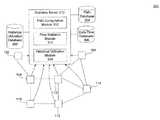
- FIG. 3is a diagram illustrating a statistics server that collects data on network characteristics.
- FIGS. 4A-Bare diagrams illustrating configuration of the network to route data over the path.
- FIG. 5is a diagram illustrating computation of the fast path in greater detail.
- FIG. 6is a flowchart illustrating a method for determining a path according to historical characteristics for a data flow and configuring the path through the network.
- SDNssoftware defined networks
- SDNscan beneficially account for the global network topology in making routing decisions.
- SDNsmay be able to look at historical usage of various interconnecting links on the network to determine which path to select for a particular data flow.
- Embodiments disclosed hereinaccount for not only the historical usage of the network links, but also historical characteristics of similar data flows. For example, embodiments may determine that data flows of a particular type—such as, for example, HTTP (Hypertext Transfer Protocol) sessions to salesforce.com—have an average bandwidth and duration. Embodiments may evaluate that average bandwidth and availability against the collected data describing the past bandwidth and availability of similar flows traversing links along the path.
- HTTPHypertext Transfer Protocol
- embodimentsmay pre-compute network paths for various data types. Further, embodiments may pre-compute the network paths for different times of day. Once pre-computed, the data paths may be stored in a database. Then, when a data stream having the data type is received, embodiments may retrieve the appropriate network path from the database.
- FIG. 1is a diagram illustrating a communication network 100 that determines a path for a data flow based on historical characteristics, according to an embodiment.
- Communication network 100may be a local area network (LAN), metropolitan area network (MAN), or wide area network (WAN). It may utilize any point-to-point or multipoint-to-multipoint networking protocols.
- the network access protocols usedmay include, for example, Multi-Protocol Label Switching (MPLS), Ethernet, Asynchronous Transfer Mode (ATM), High-Level Data Link Control (HDLC), or Packet Relay.
- MPLSMulti-Protocol Label Switching
- ATMAsynchronous Transfer Mode
- HDLCHigh-Level Data Link Control
- Packet RelayPacket Relay
- Communication network 100includes a plurality of forwarding devices, such as forwarding devices 102 , 104 , 106 , 108 , 110 , 112 , and 114 , interconnected by links.
- forwarding devices 104 and 106are connected by a link 130 .
- the forwarding devicesare devices that forward packets, including devices at the data link layer (Open Systems Interconnection layer 2) and the network layer (Open Systems Interconnection layer 3).
- Link 130may have the usage pattern illustrated in a chart 132 .
- the usage patternmay repeat over a particular cycle, such as one week, reflecting cyclical patterns.
- the cyclemay be divided into time slices, such as five minute intervals.
- link 130may have an average utilization, in other words an average amount of bandwidth being used.
- link 130may also have an average availability, in other words an average amount of available bandwidth across the line.
- the bandwidth utilized across link 130spikes during a time slice 134 .
- FIG. 1shows that the bandwidth utilized across link 130 spikes during time slice 134
- FIG. 1also shows that, during time slice 134 , the bandwidth used by a data flow 120 also spikes.
- FIG. 1shows that data flow 120 is being transferred from forwarding device 102 to forwarding device 108 .
- the datamay be the form of data flow from a particular source computing device or network and to a particular destination computing device or network.
- Data flow 120has a usage pattern illustrated in a chart 122 , and chart 122 shows that the data flow spikes during time slice 134 .
- communication network 100determines whether, during time slice 134 , link 130 may have insufficient capacity to transfer data flow 120 without the network becoming saturated and overloaded. Accordingly, the communication network 100 may redirect data flow 120 onto a different path as illustrated in FIG. 2 .
- FIG. 2is a diagram illustrating how data flow 120 is redirected along a determined path in the communication network 100 , according to an embodiment.
- communication network 100determines, according to historical usage data of the interconnecting links, an alternate path for data flow 120 .
- the alternate pathavoids link 130 , connecting forwarding devices 104 and 106 .
- data flow 120is transferred from forwarding device 104 around forwarding devices 110 and 112 to forwarding device 106 .
- embodimentsuse historical data to predict how data flow 120 may impact network utilization among various links and to route the path to avoid potential bottlenecks.
- the remainder of the Detailed Descriptionis divided into four sections.
- the first sectiondescribes, with respect to FIG. 3 , collecting the historical network data.
- the second sectiondescribes, with respect to FIGS. 4A-B , using a control device to establish a path through the network.
- the fourth sectiondescribes, with respect to FIG. 5 , calculating a path in greater detail.
- the fifth and final sectiondescribes, with respect to FIG. 6 , a method for determining a path according to historical characteristics for a data flow and configuring the path through the network.
- FIG. 3is a diagram illustrating a system 300 for collecting statistics along a path.
- System 300includes the forwarding devices of communication network 100 illustrated in FIGS. 1 and 2 .
- System 300also includes a statistics server 310 that collects data on network characteristics.
- Statistics server 310is coupled to a historical utilization database 302 , a path database 304 , and a data flow database 306 , and includes a historical utilization module 316 , a flow statistics module 314 , and a path computation module 312 . Each module is discussed in turn.
- Historical utilization module 316collects historical usage data of the network.
- historical utilization module 316may collect the amount of bandwidth utilized on each link of the network. More particularly, historical utilization module 316 may collect the amount of bandwidth utilized on each link of the network during each time slice of a time cycle. To collect the bandwidth data, historical utilization module 316 may communicate with the various network forwarding devices, which monitor link utilization.
- historical utilization module 316On collecting the utilization information, historical utilization module 316 stores the information in historical utilization database 302 . As multiple time cycles elapse, historical utilization module 316 may aggregate data for each slice. For example, historical utilization module 316 may determine an average, or a moving average, of utilization across each link during the time slice. Historical utilization module 316 may also determine a variance of the utilization across each link during the time slice. The variance may indicate a level of confidence (e.g., known statistical method such as the 95th percentile) in the average utilization and, using known statistical methods, may be used in predicting whether the link will have the availability in the future.
- level of confidencee.g., known statistical method such as the 95th percentile
- statistics server 310In addition to collecting data on link usage, statistics server 310 also collects data on data flows using flow statistics module 314 . Like historical utilization module 316 , flow statistics module 314 may communicate with the various forwarding devices to collect data on the data flows.
- a data flowmay be identified as data having a particular type, and the type may be defined as data having a particular source Internet Protocol (IP) address, source Transport Control Protocol (TCP) or User Datagram Protocol (UDP) port, destination IP address, destination TCP port, or any combination thereof.
- IPInternet Protocol
- TCPsource Transport Control Protocol
- UDPUser Datagram Protocol
- destination IP addressdestination IP address
- destination TCP portor any combination thereof.
- one data typemay be HTTP data (which has destination TCP port 80 ) addressed to salesforce.com (which has a particular destination IP address).
- Flow statistics module 314collects data describing attributes consistent with that type of data flow. For example, flow statistics module 314 may collect data on an amount of bandwidth consumed by a particular data flow and a length of the particular data flow. The length may be measured, for example, in time duration or a total amount of data transferred. Once collected, flow statistics module 314 may store the attributes in data flow database 306 . Like historical utilization module 316 , once flow statistics module 314 collects the data, it may aggregate it. Flow statistics module 314 may aggregate the data by, for example, taking an average or a moving average. In particular, flow statistics module 314 may determine an average amount of bandwidth and an average length for each type of data flow.
- flow statistics module 314may also determine a variance of the various attributes. Like with historical utilization module 316 , the variance may be used, using known statistical techniques, to establish a confidence in predicting whether a link can handle a data flow. Not all flows may be required to be collected: a statistical sampling of flows may be used to aggregate information used to describe particular flows.
- path computation module 312determines a path through a plurality of interconnected forwarding devices from the source to the destination for each data type.
- the pathmay includes network links and forwarding devices. In an embodiment, the path does not include the control device.
- path computation module 312may determine a path defining how to transmit the data flow through the network during each time slice.
- the data typemay be identified as a data flow having a particular source and destination or it may be identified as having just a particular source or a particular destination. In that case, not only may path computation module 312 compute paths for each time slice, path computation module 312 may compute paths for various possible sources or destinations that may transmit or receive flows having the type. More detail on how path computation module 312 computes the paths is provided below with respect to FIG. 5 .
- path computation module 312may take into account latency, jitter, packet loss, or any other performance metric across various paths, the user's service level agreement, or the type of data being transferred. For example, broadcast video data may require a great deal of bandwidth, but latency may be relatively unimportant. Voice-over-IP (VoIP) data, on the other hand, may not require as much bandwidth, but latency may be more important. For broadcast video data, the control device could select a high-bandwidth, high-latency path, and, for VoIP data, the control device could select a low-bandwidth, low-latency path.
- VoIPVoice-over-IP
- path computation module 312may route data through a particular server. For example, data having a certain type or directed to a certain destination may need to be scrubbed by a particular scrubbing server en route.
- the scrubbing servermay be used to scan the data for malicious content, to monitor incoming data, or to perform other analysis on the data.
- the control devicemay determine the path such that it goes through the particular scrubbing server or set of servers.
- path computation module 312computes the paths
- path computation module 312stores them in path database 304 , which is used to route data through the network as illustrated in FIGS. 4A-B .
- FIGS. 4A-Bare diagrams illustrating configuration of the network to route data over the path using a control device 440 .
- FIG. 4Ashows a diagram 400 illustrating a data stream transmitted from network user 444 to destination server 446 .
- the data streamincludes packets 402 , 404 , 406 , 408 , 410 , and 412 .
- packet 402When the first packet of the data stream—packet 402 —reaches forwarding device 102 , it is routed to control device 440 .
- Control device 440determines that this packet belongs to a new data stream and starts the process of establishing a fast path for the stream.
- control device 440may utilize path computation module 312 in FIG. 3 to compute the path in real time. As described above for FIG. 3 and in greater detail below for FIG. 5 , the computation may take into account an amount of bandwidth that type of data flow has historically consumed.
- control device 440may retrieve a pre-computed path. For retrieval of a pre-computed path, path control device 440 includes a path selection module 442 that, when a new data stream is received at control device 440 , retrieves the requested path from path database 304 .
- path database 304includes paths associated with various types.
- a typemay be defined by the source and destination IP address or the source and destination port.
- path database 304may have a path associated with data from the IP address of source port 444 to the IP address of destination 446 and having a TCP destination port 80 , designating HTTP traffic.
- Path database 304may have an entry for that type, indicating a path.
- Path database 304may also have multiple entries for that type, each with a path for a different time slice. In that embodiment, path database 304 may retrieve the path for the type of the data flow at a time slice corresponding to the current time.
- control deviceAfter determining the fast path, the control device updates routing tables for each forwarding device along the path as illustrated in FIG. 4B .
- FIG. 4Bshows a diagram 450 illustrating how control device 440 configures the network forwarding devices to establish the path between user 444 and server 446 .
- Control device 440includes a routing module 452 that sets up the path selected by path selection module 442 .
- routing table module 452determines routing tables for respective forwarding devices along the path.
- routing table module 452may determine a routing table that indicates which port to route data from the data stream.
- the routing tablesindicate how to forward data such that data from the data stream will be routed along the path.
- the updated routing tablesmay instruct the forwarding device how to forward packets having a particular combination of source/destination addresses and source/destination ports.
- the data streammay be identified with a label and the updated routing table may indicate how to forward packets having the label.
- Routing table module 452transmits the respective routing tables to configure the respective forwarding devices along the path.
- control device 102determines that the data stream between user 444 and server 446 follows the path including forwarding devices 106 , 108 , 112 , and 110 .
- the control device 102sends the updated routing tables using the configuration commands 422 , 424 , 426 , and 428 . These configuration commands configure all the forwarding devices on the fast path connecting user 444 to destination 446 .
- command 422instructs forwarding device 102 to forward packets in the data stream to forwarding device 104 ; command 424 instructs forwarding device 104 to forward the packets to forwarding device 110 ; command 426 instructs forwarding device 110 to forward the packets to forwarding device 112 ; command 428 instructs forwarding device 112 to forward the packets to forwarding device 106 ; command 430 instructs forwarding device 106 to forward the packets to forwarding device 108 ; and command 428 instructs forwarding device 108 to forward the packets to destination 446 .
- the control devicemay program forwarding devices using OpenFlow, Path Computation Element Protocol, or some other method.
- control device 102On receipt of these packets, control device 102 routes them to their destination using a default path. In this way, while the path through the network is being established, packets may continue to be routed to their destination, avoiding the need to buffer the initial packets in the edge forwarding device.
- dataflows along the fast path set up by the control device.
- datamay flow at a greater rate through the forwarding devices and lower end to end latency, since it no longer goes through the control device.
- FIG. 5is a diagram 500 of the calculation of a fast path in greater detail.
- Diagram 500illustrates a network connecting customer network 502 to destination network 504 .
- Customer network 502is coupled to a forwarding device 510 and destination network 504 is coupled to a forward device 516 .
- Forwarding devices 516 and 510are connected to each other through forwarding devices 512 and 514 .
- Each of the forwarding deviceshave routing tables that are determined by a control device 506 .
- forwarding device 510is connected to forwarding devices 512 and 514 by links 520 and 524 respectively, and forwarding devices 512 and 514 are connected to forwarding device 516 by links 522 and 526 respectively.
- historical usage datais collected for each of the links.
- the historical usage datamay provide information on usage of the link over a periodic time cycle, such as one week.
- link 500 's historical usage informationis illustrated in chart 530 ;
- link 524 's usage informationis illustrated in chart 534 ;
- link 522 's usage informationis illustrated in chart 532 ;
- link 526 's usage information scopeillustrated in chart 536 .
- Data flow 562has a particular type defined by its source IP address, destination IP address, source port, destination port, or any combination thereof. Data is collected describing the behavior of data flow 562 , for example, its duration and the bandwidth it consumes.
- Time period 550is determined and used to calculate the path.
- Time period 550is a portion of a particular time cycle, for example, including a plurality of time slices (e.g., 5 min. intervals within the week cycle).
- time period 550may run from the current time until the end of the data flow's typical duration. For example, if the data flow is received on Monday at 5:25 PM and data flows of that type typically run for 20 minutes, then time period 550 may start at 5:25 PM run until 5:45 PM on Monday. Historical usage data collected during that time cycle may then be used to calculate the path.
- a different time periodmay be determined for each time slice, and a path may be determined for each time period. For example, if the data flow typically runs for 20 minutes, a first time period may be determined as 12:00-12:20 AM on Sunday, the second time period may be determined as 12:05-12:25 AM on Sunday, and so on. Then, a path is calculated for each of the time periods. When a new data flow comes in, the path is selected that corresponds to the time that the data flows are received. In the example above, if the data flow is received at 12:00 AM on a Sunday, the path for the first time period would be selected; if the data flow is received at 12:05 AM on a Sunday, the path for the second time period would be selected; and so on.
- various candidate pathsare first determined, and historical usage along those candidate paths is evaluated and compared. Between customer network 502 and destination network 504 , there are two candidate paths. The first candidate path is along links 520 and 522 , and the second candidate path is along links 524 and 526 .
- links 520 and 522have an amount of available bandwidth 540 and 542 respectively.
- the available bandwidthmay be the amount of additional capacity the link could handle before becoming saturated. It may also account for a failure scenario where one or more links in the network are down (such as other links in the network ring) and links 520 or 522 have to carry both its normal traffic and failover traffic that would have otherwise travelled over the down link.
- Link 520 's and 522 's available bandwidthis compared to the amount of bandwidth typically consumed by data flow 560 . If the link 520 and 522 both have enough bandwidth for data flow 560 , the first candidate path may be selected.
- the same evaluation that is made for the first candidate pathis also made for the second candidate path, which includes links 524 and 526 .
- Historical usage during time period 550is determined for links 524 and 526 .
- links 524 and 526have an amount of available bandwidth 544 and 546 respectively.
- Link 524 's and 526 's available bandwidthis compared to the amount of bandwidth typically consumed by data flow 560 . if the link 524 and 526 both have enough bandwidth for data flow 560 , the first candidate path may be selected.
- link 522 's available bandwidth 542may be insufficient for data flow 560 .
- the second candidate pathsmay be selected.
- both pathshave availability, other factors may be used to select which path to use. For example, the path with the most availability may be used. In another example, latency may be approximated and the path with the least latency may be selected.
- FIG. 6is a flowchart illustrating a method 600 for determining a path according to historical characteristics for a data flow and configuring the path through the network.
- a request to create a path through the plurality of interconnected forwarding devices for a new data streamis received at a control device.
- the requestmay be in the form of a first packet in the data stream or other type of request.
- the new data stream's typemay be determined.
- the typemay be identified, for example, based on source IP address, destination IP address, source TCP port, or destination TCP port.
- the historical usage characteristicsmay include an amount of bandwidth utilized by data streams previously transmitted of the type and a length of data streams of the types that were previously transmitted.
- a path through a plurality of interconnected forwarding devicesis determined at step 608 .
- the pathspans from the source to the destination.
- the pathmay be calculated when the request is received at step 602 or may be pre-calculated and only retrieved when the request is received at step 602 .
- historical usage information of the network linksmay also be used.
- the historical usage datamay include utilization of the links at a plurality of time slices during a plurality of previous time cycles.
- the time cyclesmay represent periodic time intervals having a pattern of repeated utilization.
- the time slicesmay represent sub-intervals in the periodic time intervals.
- time slices the new data stream will occupymust be determined.
- the time slicesmay be determined based on the typical length of the data stream.
- a plurality of candidate paths connecting the source and destinationare evaluated.
- a utilization of links along the candidate path for the time slices that the new data stream will occupyis determined.
- an amount of available bandwidth on the path during the time slicesis determined.
- the determined amount of available bandwidth for the plurality of candidate pathsis compared with the data stream's needed bandwidth. Based on the comparison, a candidate path is selected for the new data stream at step 608 .
- routing tablesare determined to implement the path at step 610 .
- a routing tableis determined for respective forwarding devices along the path.
- the routing tableindicates which port of the forwarding device to route data from the new data stream along the path determined at step 608 .
- the routing tablesare transmitted to configure the respective forwarding devices to forward data along the determined path.
- the term “user,” as used herein,may encompass both a customer of the network connectivity service, such as an employee of a business that utilizes the network connectivity service, and a network administrator of the service provider itself. Users may also be at different companies or organizations.
- Historical utilization database 302 , path database 304 and data flow database 306may be any stored type of structured memory, including a persistent memory.
- each databasemay be implemented as a relational database, file system, document store, or BigData store.
- Each of the devices and modules in FIG. 6may be implemented in hardware, software, firmware, or any combination thereof.
- Each of the devices and modules in FIG. 6may be implemented on the same or different computing devices.
- Such computing devicescan include, but are not limited to, a personal computer, a mobile device such as a mobile phone, workstation, embedded system, game console, television, set-top box, or any other computing device.
- a computing devicecan include, but is not limited to, a device having a processor and memory, including a non-transitory memory, for executing and storing instructions.
- the memorymay tangibly embody the data and program instructions.
- Softwaremay include one or more applications and an operating system.
- Hardwarecan include, but is not limited to, a processor, a memory, and a graphical user interface display.
- the computing devicemay also have multiple processors and multiple shared or separate memory components.
- the computing devicemay be a part of or the entirety of a clustered or distributed computing environment or server farm.
- Identifierssuch as “(a),” “(b),” “(i),” “(ii),” etc., are sometimes used for different elements or steps. These identifiers are used for clarity and do not necessarily designate an order for the elements or steps.
Landscapes
- Engineering & Computer Science (AREA)
- Computer Networks & Wireless Communication (AREA)
- Signal Processing (AREA)
- Computing Systems (AREA)
- Theoretical Computer Science (AREA)
- Environmental & Geological Engineering (AREA)
- Data Exchanges In Wide-Area Networks (AREA)
Abstract
Description
Claims (11)
Priority Applications (10)
| Application Number | Priority Date | Filing Date | Title |
|---|---|---|---|
| US14/250,132US8811172B1 (en) | 2014-04-10 | 2014-04-10 | Network path selection using bandwidth prediction |
| US14/332,843US9210077B2 (en) | 2014-04-10 | 2014-07-16 | Network path selection using bandwidth prediction |
| EP15162363.4AEP2930891B1 (en) | 2014-04-10 | 2015-04-02 | Network path selection using bandwidth prediction |
| JP2016560530AJP6562563B2 (en) | 2014-04-10 | 2015-04-02 | Network path selection using bandwidth prediction |
| PCT/US2015/024152WO2015157094A1 (en) | 2014-04-10 | 2015-04-02 | Network path selection using bandwidth prediction |
| CN201580019053.0ACN106165354B (en) | 2014-04-10 | 2015-04-02 | Network path selection using bandwidth prediction |
| CA2887738ACA2887738C (en) | 2014-04-10 | 2015-04-09 | Network path selection using bandwidth prediction |
| US14/961,551US9667542B2 (en) | 2014-04-10 | 2015-12-07 | Network path selection using bandwidth prediction |
| HK16103775.7AHK1215832B (en) | 2014-04-10 | 2016-04-01 | Network path selection using bandwidth prediction |
| US15/605,468US10091107B2 (en) | 2014-04-10 | 2017-05-25 | Network path selection using bandwidth prediction |
Applications Claiming Priority (1)
| Application Number | Priority Date | Filing Date | Title |
|---|---|---|---|
| US14/250,132US8811172B1 (en) | 2014-04-10 | 2014-04-10 | Network path selection using bandwidth prediction |
Related Child Applications (1)
| Application Number | Title | Priority Date | Filing Date |
|---|---|---|---|
| US14/332,843ContinuationUS9210077B2 (en) | 2014-04-10 | 2014-07-16 | Network path selection using bandwidth prediction |
Publications (1)
| Publication Number | Publication Date |
|---|---|
| US8811172B1true US8811172B1 (en) | 2014-08-19 |
Family
ID=51301732
Family Applications (4)
| Application Number | Title | Priority Date | Filing Date |
|---|---|---|---|
| US14/250,132ActiveUS8811172B1 (en) | 2014-04-10 | 2014-04-10 | Network path selection using bandwidth prediction |
| US14/332,843ActiveUS9210077B2 (en) | 2014-04-10 | 2014-07-16 | Network path selection using bandwidth prediction |
| US14/961,551ActiveUS9667542B2 (en) | 2014-04-10 | 2015-12-07 | Network path selection using bandwidth prediction |
| US15/605,468ActiveUS10091107B2 (en) | 2014-04-10 | 2017-05-25 | Network path selection using bandwidth prediction |
Family Applications After (3)
| Application Number | Title | Priority Date | Filing Date |
|---|---|---|---|
| US14/332,843ActiveUS9210077B2 (en) | 2014-04-10 | 2014-07-16 | Network path selection using bandwidth prediction |
| US14/961,551ActiveUS9667542B2 (en) | 2014-04-10 | 2015-12-07 | Network path selection using bandwidth prediction |
| US15/605,468ActiveUS10091107B2 (en) | 2014-04-10 | 2017-05-25 | Network path selection using bandwidth prediction |
Country Status (6)
| Country | Link |
|---|---|
| US (4) | US8811172B1 (en) |
| EP (1) | EP2930891B1 (en) |
| JP (1) | JP6562563B2 (en) |
| CN (1) | CN106165354B (en) |
| CA (1) | CA2887738C (en) |
| WO (1) | WO2015157094A1 (en) |
Cited By (17)
| Publication number | Priority date | Publication date | Assignee | Title |
|---|---|---|---|---|
| US20150319078A1 (en)* | 2014-05-02 | 2015-11-05 | Futurewei Technologies, Inc. | Computing Service Chain-Aware Paths |
| US20160234290A1 (en)* | 2015-02-11 | 2016-08-11 | Flipboard, Inc. | Providing digital content for offline consumption |
| US20160255118A1 (en)* | 2013-12-26 | 2016-09-01 | Huawei Technologies Co., Ltd. | Network traffic control device, and security policy configuration method and apparatus thereof |
| WO2016146853A1 (en)* | 2015-03-19 | 2016-09-22 | Belgacom International Carrier Services | Method and system for managing network utilisation |
| GB2536860A (en)* | 2014-11-28 | 2016-10-05 | Aria Networks Ltd | Scheduling traffic in a telecommunications network |
| US20170048118A1 (en)* | 2015-08-13 | 2017-02-16 | Electronics And Telecommunications Research Institute | Apparatus and method for collecting adaptive flow statistics data in carrier network |
| US9699673B1 (en) | 2016-02-23 | 2017-07-04 | At&T Intellectual Property I, L.P. | Maintaining active sessions during subscriber management system maintenance activities |
| US9825846B1 (en)* | 2015-09-22 | 2017-11-21 | Amazon Technologies, Inc. | Multi-path routing |
| US9860159B1 (en)* | 2015-09-22 | 2018-01-02 | Amazon Technologies, Inc. | Multi-path routing |
| US10044604B1 (en) | 2015-09-22 | 2018-08-07 | Amazon Technologies, Inc. | Multi-path routing |
| WO2018202297A1 (en)* | 2017-05-04 | 2018-11-08 | Huawei Technologies Co., Ltd. | Network computing device, method and system for time-series forecasting based on a moving-median algorithm |
| US20180367445A1 (en)* | 2017-06-20 | 2018-12-20 | Cisco Technology, Inc. | Network path selection |
| US10193796B2 (en) | 2014-11-28 | 2019-01-29 | Aria Networks Limited | Modeling a border gateway protocol network |
| US10360514B2 (en) | 2016-03-03 | 2019-07-23 | At&T Intellectual Property I, L.P. | Method and system to dynamically enable SDN network learning capability in a user-defined cloud network |
| US10791034B2 (en) | 2014-11-28 | 2020-09-29 | Aria Networks Limited | Telecommunications network planning |
| US11025480B2 (en)* | 2016-10-13 | 2021-06-01 | Prodatakey, Inc. | Automated troubleshooting of a wireless network using a wireless network control system |
| US20230261736A1 (en)* | 2022-02-15 | 2023-08-17 | Hughes Network Systems | Method and System for Hybrid Software Defined Networking in a Terrestrial Plus Mobile Network Node Network |
Families Citing this family (12)
| Publication number | Priority date | Publication date | Assignee | Title |
|---|---|---|---|---|
| US8811172B1 (en) | 2014-04-10 | 2014-08-19 | tw telecom holdings inc. | Network path selection using bandwidth prediction |
| IN2015CH04763A (en)* | 2015-09-08 | 2015-09-25 | Wipro Ltd | |
| CN105791168A (en)* | 2016-02-24 | 2016-07-20 | 中国联合网络通信集团有限公司 | Method and device for acquiring network resources |
| SG11201807512RA (en)* | 2016-07-27 | 2018-09-27 | Megaport Services Pty Ltd | Provisioning private network connections |
| WO2018080898A1 (en)* | 2016-10-25 | 2018-05-03 | Extreme Networks, Inc. | Near-uniform load balancing in a visibility network via usage prediction |
| CN109218201B (en) | 2017-06-30 | 2021-05-18 | 华为技术有限公司 | A method, controller and network device for generating a forwarding entry |
| US11297563B2 (en) | 2017-12-18 | 2022-04-05 | Nec Corporation | Communication apparatus, communication system, communication control method, and program |
| US10862964B2 (en)* | 2018-09-18 | 2020-12-08 | At&T Intellectual Property I, L.P. | Peer packet transport |
| CN110290027B (en)* | 2019-07-15 | 2021-01-15 | 华北电力大学 | A bandwidth prediction method and system for power distribution communication services |
| US11876710B2 (en)* | 2021-01-20 | 2024-01-16 | Oracle International Corporation | Dynamic IP routing in a cloud environment |
| CN113300958A (en)* | 2021-05-24 | 2021-08-24 | 北京字跳网络技术有限公司 | Message transmission method and device, electronic equipment and storage medium |
| US20230344808A1 (en)* | 2022-04-25 | 2023-10-26 | Invisv Inc. | Secure network routing as a service |
Citations (7)
| Publication number | Priority date | Publication date | Assignee | Title |
|---|---|---|---|---|
| US20080049615A1 (en)* | 2006-08-22 | 2008-02-28 | Bugenhagen Michael K | System and method for dynamically shaping network traffic |
| US20120054255A1 (en)* | 2010-08-25 | 2012-03-01 | Ab Initio Technology Llc | Evaluating dataflow graph characteristics |
| US8526985B2 (en)* | 2009-11-30 | 2013-09-03 | Alcatel Lucent | System and method of geo-concentrated video detection |
| US8619820B2 (en)* | 2006-08-22 | 2013-12-31 | Centurylink Intellectual Property Llc | System and method for enabling communications over a number of packet networks |
| US8619600B2 (en)* | 2006-08-22 | 2013-12-31 | Centurylink Intellectual Property Llc | System and method for establishing calls over a call path having best path metrics |
| US20140064086A1 (en)* | 2006-08-22 | 2014-03-06 | Centurylink Intellectual Property Llc | System and method for managing network communications |
| US8682812B1 (en)* | 2010-12-23 | 2014-03-25 | Narus, Inc. | Machine learning based botnet detection using real-time extracted traffic features |
Family Cites Families (16)
| Publication number | Priority date | Publication date | Assignee | Title |
|---|---|---|---|---|
| CA2413029A1 (en) | 2000-06-14 | 2001-12-27 | Coreexpress, Inc. | Internet route deaggregation and route selection preferencing |
| US6775701B1 (en) | 2000-08-15 | 2004-08-10 | Nortel Networks Limited | Oversubscribing network resources |
| CN1200538C (en)* | 2003-07-11 | 2005-05-04 | 清华大学 | Method for selecting route by accounting and controlling node status |
| EP1847071A4 (en) | 2005-01-26 | 2010-10-20 | Internet Broadcasting Corp B V | MULTI-DIFFUSION IN LAYERS AND EXACT ATTRIBUTION OF BANDWIDTH AND PRIORIZATION OF PACKETS |
| CN101047660A (en)* | 2006-03-28 | 2007-10-03 | 朗迅科技公司 | Method for transmitting data |
| US7843831B2 (en) | 2006-08-22 | 2010-11-30 | Embarq Holdings Company Llc | System and method for routing data on a packet network |
| US8897306B2 (en)* | 2007-08-22 | 2014-11-25 | Nippon Telegraph And Telephone Corporation | Path management control method, path management control program, path management controller and path management control system |
| CN101562534B (en)* | 2009-05-26 | 2011-12-14 | 中山大学 | Network behavior analytic system |
| JP5493965B2 (en)* | 2010-02-15 | 2014-05-14 | 日本電気株式会社 | BAND CONTROL SYSTEM, BAND CONTROL DEVICE, BAND CONTROL METHOD, AND BAND CONTROL PROGRAM |
| JP5418289B2 (en) | 2010-02-23 | 2014-02-19 | 富士通株式会社 | Route determination device, route determination method and route determination program |
| JP2012074825A (en)* | 2010-09-28 | 2012-04-12 | Hitachi Solutions Ltd | Qos guaranteed network system, centralized controller, and control method of centralized controller |
| US20120320920A1 (en)* | 2010-12-01 | 2012-12-20 | Ippei Akiyoshi | Communication system, control device, communication method, and program |
| JP5987841B2 (en) | 2011-06-02 | 2016-09-07 | 日本電気株式会社 | COMMUNICATION SYSTEM, CONTROL DEVICE, TRANSFER NODE, COMMUNICATION SYSTEM CONTROL METHOD AND PROGRAM |
| US8654629B1 (en) | 2011-06-29 | 2014-02-18 | Amazon Technologies, Inc. | Network capacity planning |
| US8611355B1 (en) | 2013-09-03 | 2013-12-17 | tw telecom holdings inc. | Buffer-less virtual routing |
| US8811172B1 (en) | 2014-04-10 | 2014-08-19 | tw telecom holdings inc. | Network path selection using bandwidth prediction |
- 2014
- 2014-04-10USUS14/250,132patent/US8811172B1/enactiveActive
- 2014-07-16USUS14/332,843patent/US9210077B2/enactiveActive
- 2015
- 2015-04-02EPEP15162363.4Apatent/EP2930891B1/ennot_activeNot-in-force
- 2015-04-02WOPCT/US2015/024152patent/WO2015157094A1/enactiveApplication Filing
- 2015-04-02CNCN201580019053.0Apatent/CN106165354B/ennot_activeExpired - Fee Related
- 2015-04-02JPJP2016560530Apatent/JP6562563B2/ennot_activeExpired - Fee Related
- 2015-04-09CACA2887738Apatent/CA2887738C/enactiveActive
- 2015-12-07USUS14/961,551patent/US9667542B2/enactiveActive
- 2017
- 2017-05-25USUS15/605,468patent/US10091107B2/enactiveActive
Patent Citations (7)
| Publication number | Priority date | Publication date | Assignee | Title |
|---|---|---|---|---|
| US20080049615A1 (en)* | 2006-08-22 | 2008-02-28 | Bugenhagen Michael K | System and method for dynamically shaping network traffic |
| US8619820B2 (en)* | 2006-08-22 | 2013-12-31 | Centurylink Intellectual Property Llc | System and method for enabling communications over a number of packet networks |
| US8619600B2 (en)* | 2006-08-22 | 2013-12-31 | Centurylink Intellectual Property Llc | System and method for establishing calls over a call path having best path metrics |
| US20140064086A1 (en)* | 2006-08-22 | 2014-03-06 | Centurylink Intellectual Property Llc | System and method for managing network communications |
| US8526985B2 (en)* | 2009-11-30 | 2013-09-03 | Alcatel Lucent | System and method of geo-concentrated video detection |
| US20120054255A1 (en)* | 2010-08-25 | 2012-03-01 | Ab Initio Technology Llc | Evaluating dataflow graph characteristics |
| US8682812B1 (en)* | 2010-12-23 | 2014-03-25 | Narus, Inc. | Machine learning based botnet detection using real-time extracted traffic features |
Cited By (34)
| Publication number | Priority date | Publication date | Assignee | Title |
|---|---|---|---|---|
| US10051007B2 (en)* | 2013-12-26 | 2018-08-14 | Huawei Technologies Co., Ltd. | Network traffic control device, and security policy configuration method and apparatus thereof |
| US20160255118A1 (en)* | 2013-12-26 | 2016-09-01 | Huawei Technologies Co., Ltd. | Network traffic control device, and security policy configuration method and apparatus thereof |
| US9634867B2 (en)* | 2014-05-02 | 2017-04-25 | Futurewei Technologies, Inc. | Computing service chain-aware paths |
| US20150319078A1 (en)* | 2014-05-02 | 2015-11-05 | Futurewei Technologies, Inc. | Computing Service Chain-Aware Paths |
| US9871719B2 (en) | 2014-05-02 | 2018-01-16 | Futurewei Technologies, Inc. | Computing service chain-aware paths |
| GB2536860A (en)* | 2014-11-28 | 2016-10-05 | Aria Networks Ltd | Scheduling traffic in a telecommunications network |
| US10791034B2 (en) | 2014-11-28 | 2020-09-29 | Aria Networks Limited | Telecommunications network planning |
| US10193796B2 (en) | 2014-11-28 | 2019-01-29 | Aria Networks Limited | Modeling a border gateway protocol network |
| US10574567B2 (en) | 2014-11-28 | 2020-02-25 | Aria Networks Limited | Modeling a border gateway protocol network |
| US20160234290A1 (en)* | 2015-02-11 | 2016-08-11 | Flipboard, Inc. | Providing digital content for offline consumption |
| WO2016130356A1 (en)* | 2015-02-11 | 2016-08-18 | Flipboard, Inc. | Providing digital content for offline consumption |
| US10015625B2 (en)* | 2015-02-11 | 2018-07-03 | Flipboard, Inc. | Providing digital content for offline consumption |
| WO2016146853A1 (en)* | 2015-03-19 | 2016-09-22 | Belgacom International Carrier Services | Method and system for managing network utilisation |
| US20170048118A1 (en)* | 2015-08-13 | 2017-02-16 | Electronics And Telecommunications Research Institute | Apparatus and method for collecting adaptive flow statistics data in carrier network |
| US10263864B2 (en)* | 2015-08-13 | 2019-04-16 | Electronics And Telecommunications Research Institute | Apparatus and method for collecting adaptive flow statistics data in carrier network |
| US9860159B1 (en)* | 2015-09-22 | 2018-01-02 | Amazon Technologies, Inc. | Multi-path routing |
| US10924388B1 (en)* | 2015-09-22 | 2021-02-16 | Amazon Technologies, Inc. | Multi-path routing |
| US10623306B2 (en) | 2015-09-22 | 2020-04-14 | Amazon Technologies, Inc. | Multi-path routing |
| US10044604B1 (en) | 2015-09-22 | 2018-08-07 | Amazon Technologies, Inc. | Multi-path routing |
| US9825846B1 (en)* | 2015-09-22 | 2017-11-21 | Amazon Technologies, Inc. | Multi-path routing |
| US9699673B1 (en) | 2016-02-23 | 2017-07-04 | At&T Intellectual Property I, L.P. | Maintaining active sessions during subscriber management system maintenance activities |
| US10360514B2 (en) | 2016-03-03 | 2019-07-23 | At&T Intellectual Property I, L.P. | Method and system to dynamically enable SDN network learning capability in a user-defined cloud network |
| US11012875B2 (en) | 2016-03-03 | 2021-05-18 | At&T Intellectual Property I, L.P. | Method and system to dynamically enable SDN network learning capability in a user-defined cloud network |
| US11025480B2 (en)* | 2016-10-13 | 2021-06-01 | Prodatakey, Inc. | Automated troubleshooting of a wireless network using a wireless network control system |
| WO2018202297A1 (en)* | 2017-05-04 | 2018-11-08 | Huawei Technologies Co., Ltd. | Network computing device, method and system for time-series forecasting based on a moving-median algorithm |
| CN110574337A (en)* | 2017-05-04 | 2019-12-13 | 华为技术有限公司 | Network computing equipment, method and system for time series forecasting based on sliding median algorithm |
| WO2018236724A1 (en)* | 2017-06-20 | 2018-12-27 | Cisco Technology, Inc. | NETWORK PATH SELECTION |
| US20180367445A1 (en)* | 2017-06-20 | 2018-12-20 | Cisco Technology, Inc. | Network path selection |
| US10462042B2 (en)* | 2017-06-20 | 2019-10-29 | Cisco Technology, Inc. | Network path selection |
| US11245616B2 (en) | 2017-06-20 | 2022-02-08 | Cisco Technology, Inc. | Network path selection |
| US11611503B2 (en) | 2017-06-20 | 2023-03-21 | Cisco Technology, Inc. | Network path selection |
| US11863429B2 (en) | 2017-06-20 | 2024-01-02 | Cisco Technology, Inc. | Network path selection |
| US20230261736A1 (en)* | 2022-02-15 | 2023-08-17 | Hughes Network Systems | Method and System for Hybrid Software Defined Networking in a Terrestrial Plus Mobile Network Node Network |
| US12212400B2 (en)* | 2022-02-15 | 2025-01-28 | Hughes Network Systems, Llc | Method and system for hybrid software defined networking in a terrestrial plus mobile network node network |
Also Published As
| Publication number | Publication date |
|---|---|
| HK1215832A1 (en) | 2016-09-15 |
| US20160156556A1 (en) | 2016-06-02 |
| US9667542B2 (en) | 2017-05-30 |
| CA2887738A1 (en) | 2015-06-15 |
| US10091107B2 (en) | 2018-10-02 |
| EP2930891B1 (en) | 2016-11-23 |
| WO2015157094A1 (en) | 2015-10-15 |
| US20170339057A1 (en) | 2017-11-23 |
| EP2930891A1 (en) | 2015-10-14 |
| JP2017511068A (en) | 2017-04-13 |
| US9210077B2 (en) | 2015-12-08 |
| CN106165354B (en) | 2019-12-10 |
| CA2887738C (en) | 2016-08-30 |
| JP6562563B2 (en) | 2019-08-21 |
| CN106165354A (en) | 2016-11-23 |
| US20150295822A1 (en) | 2015-10-15 |
Similar Documents
| Publication | Publication Date | Title |
|---|---|---|
| US10091107B2 (en) | Network path selection using bandwidth prediction | |
| US10673741B2 (en) | Control device discovery in networks having separate control and forwarding devices | |
| US10666563B2 (en) | Buffer-less virtual routing | |
| US8780716B2 (en) | System and method for service assurance in IP networks | |
| HK1215832B (en) | Network path selection using bandwidth prediction | |
| HK1213383B (en) | Control device discovery in networks having separate control and forwarding devices | |
| HK1226212B (en) | Buffer-less virtual routing |
Legal Events
| Date | Code | Title | Description |
|---|---|---|---|
| FEPP | Fee payment procedure | Free format text:PAYOR NUMBER ASSIGNED (ORIGINAL EVENT CODE: ASPN); ENTITY STATUS OF PATENT OWNER: LARGE ENTITY | |
| AS | Assignment | Owner name:TW TELECOM HOLDINGS, INC., COLORADO Free format text:ASSIGNMENT OF ASSIGNORS INTEREST;ASSIGNOR:SELLA, WILLIAM THOMAS;REEL/FRAME:032702/0133 Effective date:20140410 | |
| STCF | Information on status: patent grant | Free format text:PATENTED CASE | |
| AS | Assignment | Owner name:LEVEL 3 COMMUNICATIONS, LLC, COLORADO Free format text:ASSIGNMENT OF ASSIGNORS INTEREST;ASSIGNOR:TW TELECOM HOLDINGS INC.;REEL/FRAME:034290/0955 Effective date:20141120 | |
| MAFP | Maintenance fee payment | Free format text:PAYMENT OF MAINTENANCE FEE, 4TH YEAR, LARGE ENTITY (ORIGINAL EVENT CODE: M1551) Year of fee payment:4 | |
| MAFP | Maintenance fee payment | Free format text:PAYMENT OF MAINTENANCE FEE, 8TH YEAR, LARGE ENTITY (ORIGINAL EVENT CODE: M1552); ENTITY STATUS OF PATENT OWNER: LARGE ENTITY Year of fee payment:8 | |
| AS | Assignment | Owner name:WILMINGTON TRUST, NATIONAL ASSOCIATION, AS COLLATERAL AGENT, MINNESOTA Free format text:NOTICE OF GRANT OF SECURITY INTEREST IN INTELLECTUAL PROPERTY (SECOND LIEN);ASSIGNORS:LEVEL 3 COMMUNICATIONS, LLC;GLOBAL CROSSING TELECOMMUNICATIONS, INC;REEL/FRAME:069295/0749 Effective date:20241031 Owner name:WILMINGTON TRUST, NATIONAL ASSOCIATION, AS COLLATERAL AGENT, MINNESOTA Free format text:NOTICE OF GRANT OF SECURITY INTEREST IN INTELLECTUAL PROPERTY (FIRST LIEN);ASSIGNORS:LEVEL 3 COMMUNICATIONS, LLC;GLOBAL CROSSING TELECOMMUNICATIONS, INC.;REEL/FRAME:069295/0858 Effective date:20241031 |