US8810448B1 - Modular architecture for scalable phased array radars - Google Patents
Modular architecture for scalable phased array radarsDownload PDFInfo
- Publication number
- US8810448B1 US8810448B1US13/230,271US201113230271AUS8810448B1US 8810448 B1US8810448 B1US 8810448B1US 201113230271 AUS201113230271 AUS 201113230271AUS 8810448 B1US8810448 B1US 8810448B1
- Authority
- US
- United States
- Prior art keywords
- radar
- module
- chassis
- receive
- array
- Prior art date
- Legal status (The legal status is an assumption and is not a legal conclusion. Google has not performed a legal analysis and makes no representation as to the accuracy of the status listed.)
- Active, expires
Links
Images


Classifications
- G—PHYSICS
- G01—MEASURING; TESTING
- G01S—RADIO DIRECTION-FINDING; RADIO NAVIGATION; DETERMINING DISTANCE OR VELOCITY BY USE OF RADIO WAVES; LOCATING OR PRESENCE-DETECTING BY USE OF THE REFLECTION OR RERADIATION OF RADIO WAVES; ANALOGOUS ARRANGEMENTS USING OTHER WAVES
- G01S7/00—Details of systems according to groups G01S13/00, G01S15/00, G01S17/00
- G01S7/02—Details of systems according to groups G01S13/00, G01S15/00, G01S17/00 of systems according to group G01S13/00
- G01S7/027—Constructional details of housings, e.g. form, type, material or ruggedness
- G—PHYSICS
- G01—MEASURING; TESTING
- G01S—RADIO DIRECTION-FINDING; RADIO NAVIGATION; DETERMINING DISTANCE OR VELOCITY BY USE OF RADIO WAVES; LOCATING OR PRESENCE-DETECTING BY USE OF THE REFLECTION OR RERADIATION OF RADIO WAVES; ANALOGOUS ARRANGEMENTS USING OTHER WAVES
- G01S7/00—Details of systems according to groups G01S13/00, G01S15/00, G01S17/00
- G01S7/02—Details of systems according to groups G01S13/00, G01S15/00, G01S17/00 of systems according to group G01S13/00
- H—ELECTRICITY
- H01—ELECTRIC ELEMENTS
- H01Q—ANTENNAS, i.e. RADIO AERIALS
- H01Q1/00—Details of, or arrangements associated with, antennas
- H01Q1/02—Arrangements for de-icing; Arrangements for drying-out ; Arrangements for cooling; Arrangements for preventing corrosion
- H—ELECTRICITY
- H01—ELECTRIC ELEMENTS
- H01Q—ANTENNAS, i.e. RADIO AERIALS
- H01Q1/00—Details of, or arrangements associated with, antennas
- H01Q1/42—Housings not intimately mechanically associated with radiating elements, e.g. radome
- H—ELECTRICITY
- H05—ELECTRIC TECHNIQUES NOT OTHERWISE PROVIDED FOR
- H05K—PRINTED CIRCUITS; CASINGS OR CONSTRUCTIONAL DETAILS OF ELECTRIC APPARATUS; MANUFACTURE OF ASSEMBLAGES OF ELECTRICAL COMPONENTS
- H05K7/00—Constructional details common to different types of electric apparatus
- H05K7/20—Modifications to facilitate cooling, ventilating, or heating
- H05K7/20536—Modifications to facilitate cooling, ventilating, or heating for racks or cabinets of standardised dimensions, e.g. electronic racks for aircraft or telecommunication equipment
- H05K7/20627—Liquid coolant without phase change
- H05K7/20636—Liquid coolant without phase change within sub-racks for removing heat from electronic boards
- G—PHYSICS
- G01—MEASURING; TESTING
- G01S—RADIO DIRECTION-FINDING; RADIO NAVIGATION; DETERMINING DISTANCE OR VELOCITY BY USE OF RADIO WAVES; LOCATING OR PRESENCE-DETECTING BY USE OF THE REFLECTION OR RERADIATION OF RADIO WAVES; ANALOGOUS ARRANGEMENTS USING OTHER WAVES
- G01S13/00—Systems using the reflection or reradiation of radio waves, e.g. radar systems; Analogous systems using reflection or reradiation of waves whose nature or wavelength is irrelevant or unspecified
- G01S13/02—Systems using reflection of radio waves, e.g. primary radar systems; Analogous systems
- G01S2013/0236—Special technical features
- G01S2013/0245—Radar with phased array antenna
- G01S2013/0254—Active array antenna
Definitions
- a phased array antennaincludes a plurality of active circuits spaced apart from each other by known distances. Each of the active circuits is coupled through a plurality of phase shifter circuits, amplifier circuits and/or other circuits to either or both of a transmitter and receiver.
- the phase shifter, amplifier circuits and other circuitse.g., mixer circuits
- T/Rtransmit/receive
- phase shifters, amplifier and other circuitse.g., T/R modules
- an external power supplye.g., a DC power supply
- the circuitsare referred to as “active circuits” or “active components.”
- phased array antennaswhich include active circuits are often referred to as “active phased arrays.”
- Active circuitsdissipate power in the form of heat. High amounts of heat can cause active circuits to be inoperable. Thus, active phased arrays must be cooled. In one example heat-sink(s) are attached to each active circuit to dissipate the heat.
- a radar array assemblyincludes two or more vertical stiffeners each having bores with threads and a first radar module.
- the first radar moduleincludes radar transmit and receive (T/R) modules and a chassis having channels configured to receive a coolant.
- the chassisincludes shelves having ribs. The ribs have channels configured to receive the coolant and the ribs form slots to receive circuit cards disposed in parallel.
- the circuit cardsinclude the T/R modules.
- the chassisalso includes set screws attached to opposing sides of the chassis. The set screws have bores to accept fasteners to engage the threads on a corresponding one of the two or more vertical stiffeners.
- the first radar moduleis configured to operate as a stand-alone radar array.
- a radar modulein another aspect, includes radar transmit and receive (T/R) modules and a chassis having channels configured to receive a coolant.
- the chassisincludes shelves having ribs.
- the ribshave channels configured to receive the coolant.
- the ribsform slots to receive circuit cards disposed in parallel.
- the circuit cardsinclude the T/R modules.
- the radar moduleis configured to perform as a standalone radar array and perform with other radar modules to form a radar array.
- a radar radiator panelincludes a radome, cyanate ester quartz (CEQ) coupled to the radome and a stacked assembly coupled to the CEQ, the stacked assembly comprising a thermal conductive layer configured to facilitate a transfer of heat to the radome.
- CEQcyanate ester quartz
- the radar array modulemay include a dual digital receiver exciter (DDREX) module, a synthesizer module and an auxiliary power module disposed in the slots.
- the radar array assemblymay include an array plate having a first side and a second side opposite the first side, a radiator panel attached to the first side of the array plate and RF jumpers attached to the second side of the array plate.
- the array platemay be coupled to the vertical stiffeners.
- the first radar array modulemay include a digital receiver and exciter (DREX) backplane coupled to the chassis, an RF backplane coupled to the DREX backplane and an overlap beamformer having a first side and a second side opposite the first side.
- DREXdigital receiver and exciter
- the radiator panelmay include stacked assemblies each comprising a thermal conductive layer.
- the thermal conductive layermay include at least one of aluminum and copper.
- the thermal conductive layermay be greater than 1 mil.
- the thermal conductive layermay be about 60 mils.
- the radar array assemblymay include a second radar module configured to be substantially the same as the first radar module.
- a set screwmay include a notch configured to be engaged by a flat tip screwdriver.
- FIGS. 1A and 1Bare plan views of a radar module.
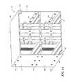
- FIGS. 2A and 2Bare plan views of different sized radar array frame structures.
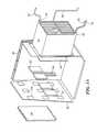
- FIG. 3Ais an exploded view of the radar module and a portion of a radar array frame structure.
- FIG. 3Bis a side-view the radar module attached to the radar array frame structure.
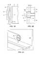
- FIG. 4Ais a plan view of a set screw.
- FIG. 4Bis a cross-sectional view of the set screw securing the chassis to a vertical stiffener.
- FIG. 5Ais a plan view of a radiator panel.
- FIG. 5Bis a plan view of a radiator housing with one stacked-patch assembly.
- FIG. 5Cis a plan view of the radiator housing taken at the line FIG. 5C in FIG. 5B .
- FIG. 5Dis a cross-sectional view of an array plate and the radiator panel.
- FIG. 5Ea cross-sectional view of the array plate and the radiator panel depicting heat flow.
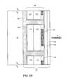
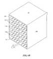
- FIGS. 6A and 6Bare plan views of a cooling chassis.
- FIG. 7is a view of a supply cold plate depicting an example of coolant flow.
- FIG. 8is a view of a return cold plate depicting an example of coolant flow.
- FIG. 9Ais a top view of a top cold plate depicting an example of coolant flow.
- FIG. 9Bis a bottom view of the top cold plate depicting an example of coolant flow.
- FIGS. 9C and 9Dare side views of the top cold plate.
- a radar modulemay be used as a building block to form various radar array sizes.
- Each radar moduleis fabricated to be identical.
- each radar modulereceives in parallel the necessary coolant, power and control signals necessary to be a stand-alone antenna array.
- the radar array sizesare scalable.
- the radar modulescan form multiple array sizes from two feet to thirty-two feet and beyond.
- a radar module 10includes a chassis 11 that includes a top cold plate 12 , a supply manifold 14 a with an input port 42 , a return manifold 14 b with an output port 22 , a bottom cold plate 16 and a front plate 18 .
- the chassis 11is configured to hold LRUs (e.g., circuit cards) such as transmit/receive integrated microwave modules (TRIMMs) 32 that include transmit/receive (T/R) modules ( 33 ), dual digital receiver exciter (DDREX) modules 34 , a synthesizer module 36 , and an auxiliary/controller module 40 .
- LRUse.g., circuit cards
- T/Rtransmit/receive integrated microwave modules
- DDREXdual digital receiver exciter
- the chassis 11performs a cooling function.
- the T/R modules 33produce high amounts of heat which must be dissipated or else the active circuits (e.g., power amplifiers) will cease to operate properly.
- the supply manifold 14 aincludes channels that receive coolant at the port 42 .
- the coolantis circulated through out the chassis 11 and removed via the return manifold 14 b out the port 22 .
- the chassis 11performs as a heat sink drawing the heat away from the active circuits (e.g., in the T/R modules 33 ).
- the chassis 11includes set screws 46 attached to the supply manifold 14 a and to the return manifold 14 b.
- the radar moduleradiates energy in a direction R.
- the T/R modules 33radiate energy in the R direction.
- the radar module 10also includes a digital receiver and exciter (DREX) backplane 54 attached to the front plate 18 , an RF backplane 50 attached to the DREX backplane and overlap beamformers 52 attached to the RF backplane.
- DREXdigital receiver and exciter
- radar modules 10may be secured inside honey-combed structures called radar array frame structures.
- a radar array frame structure 80includes an array plate 62 with vertical stiffeners 60 and horizontal stiffeners 58 attached to the array plate.
- the vertical stiffeners 60 and the horizontal stiffeners 58form cavities (e.g., a cavity 61 ) in which a single radar module 10 may be disposed inside.
- the radar module 10rests on a horizontal stiffener 58 and is secured to the vertical stiffeners using set screws 46 attached to the supply manifold 14 a and the return manifold 14 b.
- the radar array frame structure 80 in FIG. 2Acan include thirty-six radar modules 10 with an active area of about eight square meters.
- a radar array frame structure 80 ′ in FIG. 2Bcan hold one hundred and sixteen radar modules 10 with an active area of about thirty-seven square meters.
- the horizontal stiffeners 58are not used; but rather, each radar module 10 is secured to two vertical stiffeners 60 .
- a radiator panel 70is attached to one side of the array plate 62 and RF jumpers 64 are attached to the opposite side of the array plate.
- the RF jumpers 64are attached to the overlap beamformers 52 .
- each overlap beamformeris coupled to four RF jumpers 64 .
- a coolant supply line 74is coupled to the port 42 and a coolant return line 72 is coupled to the port 22 .
- Datais supplied to the radar module 10 by a line 76 and power is supplied by a line 78 .
- a set screw 46includes threads 57 that engage with threads in the supply manifold 14 a .
- the set screw 46includes a notch 49 configured to be engaged by a flat tip screwdriver to adjust its depth to reduce a horizontal tolerance h t between the supply manifold 14 a and the vertical stiffener 60 .
- the set screw 46also includes a bore 51 to receive a bolt 53 with washer 55 to secure the radar module 10 to the vertical stiffener 60 by having the threads 57 of the bolt 53 engage threads 59 of the vertical stiffener.
- the set screws 46are used to compensate for the different horizontal tolerances h t as each radar module 10 is being secured with the radar array framework 80 . Though only set screws 46 on the supply manifold 14 a are described in FIGS. 4A and 4B , one of ordinary skill in the art would recognize that set screws 46 function similarly on the return manifold 14 b.
- the radiator panel 70includes a housing 96 (e.g., an aluminum housing) with a stacked-path assembly 98 (sometimes called an element) in each cavity 100 of the housing; a radome 102 ; cyanate ester quartz (CEQ) 104 ; and an epoxy 106 to bond the stacked-patch 98 to the housing 96 .
- Each stacked-patch assembly 98includes an epoxy 108 , a multi-layer RF circuit card 110 , foam 112 , which includes cross-linked polymers, and a thermal conductive layer 114 (e.g., aluminum, copper and so forth).
- the thermal conductive layer 114is greater than 1 mil (e.g., about 60 mils).
- RF energyis supplied to the RF circuit card 110 via a connector (not shown) that protrudes thru the housing 90 .
- the radiator panel 70does not include the radome 102 , the CEQ 104 or the epoxy 106 . Also, FIGS. 5B and 5C only depict a single stacked-patch assembly 98 in one cavity 100 while the remaining cavities are empty. In one example, the radiator panel 70 is about two feet by two feet and holds about one hundred forty-four stacked path assemblies 98 .
- the CEQ 104adds structural integrity by protecting the radiator panel 70 from damage from objects colliding with the radiator panel 70 .
- the objectsmay include hail.
- the configuration of the stacked-patch assembly 98contributes to adding an anti-icing feature to the radiator panel 70 . Even though the coolant in the chassis 11 cools the T/R modules 33 there is some excess thermal energy that transfers to the array plate 62 .
- the excess thermal energy(depicted by arrows H in FIG. 5E ) flows from the array plate 62 through the housing 96 and through the thermal conductive layers 114 to the radome 102 .
- the thermal conductive layers 114 with a high thermal conductivitydirects the heat to the radome 102 .
- the thermal energy transferred to the radome 102is sufficient enough to maintain its surface at a temperature above freezing so that ice and snow does not accumulate on the radome 102 .
- the chassis 11may be configured as chassis 11 ′ that includes a supply manifold 14 a ′ and a return manifold 14 b ′ that are orientated on opposite sides than the supply manifold 14 a and the return manifold 14 b respectively in the chassis 11 .
- the chassis 11 ′includes a top cold plate 12 ′ that is oriented opposite to the top cold plate 12 and a bottom cold plate 16 ′ that is oriented opposite to the bottom cold plate 16 .
- the chassis 11 ′also includes large cold plates 118 and small cold plates 122 . These cold plates 118 , 122 include cooling ribs 124 that include channels (not shown) to carry coolant.
- Gaps between the cooling ribs 124form slots 126 that hold the TRIMMs 32 in a parallel configuration, which contributes to a more efficient cooling of the T/R modules 33 .
- the slots 126are also configured to hold the DDREX modules 34 , the synthesizer module 36 and the auxiliary/controller module 40 .
- the supply cold plate 14 a ′receives coolant through the port 42 and flows through a channel 130 as indicated by arrows D.
- the return cold plate 14 b ′includes a channel 152 that carries coolant in a flow as indicated by arrows D to the port 22 .
- the port 42receives propylene glycol water (PGW) coolant at 10 gallons per minute (gpm) and 20° C. and the port 22 returns the PGW coolant at 30° C.
- PGWpropylene glycol water
- the top cold plate 12 ′includes an upper channel 172 a running along a top portion 212 of the top cold plate 12 ′ and a lower channel 172 b running along a bottom portion 214 of the top cold plate 12 ′.
- the upper channel 172 a and the lower channel 172 bare connected by channels 172 c.
Landscapes
- Engineering & Computer Science (AREA)
- Physics & Mathematics (AREA)
- Computer Networks & Wireless Communication (AREA)
- General Physics & Mathematics (AREA)
- Radar, Positioning & Navigation (AREA)
- Remote Sensing (AREA)
- Aviation & Aerospace Engineering (AREA)
- Thermal Sciences (AREA)
- Microelectronics & Electronic Packaging (AREA)
- Variable-Direction Aerials And Aerial Arrays (AREA)
- Radar Systems Or Details Thereof (AREA)
Abstract
Description
Claims (14)
Priority Applications (2)
| Application Number | Priority Date | Filing Date | Title |
|---|---|---|---|
| US13/230,271US8810448B1 (en) | 2010-11-18 | 2011-09-12 | Modular architecture for scalable phased array radars |
| US14/323,142US9116222B1 (en) | 2010-11-18 | 2014-07-03 | Modular architecture for scalable phased array radars |
Applications Claiming Priority (2)
| Application Number | Priority Date | Filing Date | Title |
|---|---|---|---|
| US94885810A | 2010-11-18 | 2010-11-18 | |
| US13/230,271US8810448B1 (en) | 2010-11-18 | 2011-09-12 | Modular architecture for scalable phased array radars |
Related Parent Applications (1)
| Application Number | Title | Priority Date | Filing Date |
|---|---|---|---|
| US94885810AContinuation | 2010-11-18 | 2010-11-18 |
Related Child Applications (1)
| Application Number | Title | Priority Date | Filing Date |
|---|---|---|---|
| US14/323,142DivisionUS9116222B1 (en) | 2010-11-18 | 2014-07-03 | Modular architecture for scalable phased array radars |
Publications (1)
| Publication Number | Publication Date |
|---|---|
| US8810448B1true US8810448B1 (en) | 2014-08-19 |
Family
ID=51301698
Family Applications (2)
| Application Number | Title | Priority Date | Filing Date |
|---|---|---|---|
| US13/230,271Active2030-12-06US8810448B1 (en) | 2010-11-18 | 2011-09-12 | Modular architecture for scalable phased array radars |
| US14/323,142ActiveUS9116222B1 (en) | 2010-11-18 | 2014-07-03 | Modular architecture for scalable phased array radars |
Family Applications After (1)
| Application Number | Title | Priority Date | Filing Date |
|---|---|---|---|
| US14/323,142ActiveUS9116222B1 (en) | 2010-11-18 | 2014-07-03 | Modular architecture for scalable phased array radars |
Country Status (1)
| Country | Link |
|---|---|
| US (2) | US8810448B1 (en) |
Cited By (15)
| Publication number | Priority date | Publication date | Assignee | Title |
|---|---|---|---|---|
| US20120111553A1 (en)* | 2009-05-18 | 2012-05-10 | Vadim Tsoi | Heat spreading device and method therefore |
| US9647187B1 (en)* | 2013-05-30 | 2017-05-09 | Hrl Laboratories, Llc | Multi-slice two-dimensional phased array assembly |
| CN107561504A (en)* | 2017-07-27 | 2018-01-09 | 中国船舶重工集团公司第七二四研究所 | A kind of multichannel T/R inside modules three-dimensional blindmate structure implementation method |
| US10288218B2 (en) | 2015-05-14 | 2019-05-14 | Alstom Transport Technologies | System, apparatus and method for mounting a device |
| EP3543737A1 (en)* | 2018-03-22 | 2019-09-25 | Audi Ag | Motor vehicle and radar sensor assembly for a motor vehicle |
| CN113064146A (en)* | 2021-04-23 | 2021-07-02 | 沈阳工程学院 | Protection device for wind power prediction sodar and control method |
| US20210305674A1 (en)* | 2020-03-26 | 2021-09-30 | Hamilton Sundstrand Corporation | Heat exchanger rib for multi-function aperture |
| CN114325590A (en)* | 2021-12-27 | 2022-04-12 | 北京微焓科技有限公司 | Phased array radar cold drawing and phased array radar |
| JP2022536737A (en)* | 2019-06-14 | 2022-08-18 | レイセオン カンパニー | interlocking modular beamformer |
| US11437732B2 (en)* | 2019-09-17 | 2022-09-06 | Raytheon Company | Modular and stackable antenna array |
| US11489262B1 (en) | 2020-12-01 | 2022-11-01 | Raytheon Company | Radiator having a ridged feed structure |
| WO2022271271A1 (en) | 2021-06-24 | 2022-12-29 | Raytheon Company | Composable radar |
| CN116053749A (en)* | 2023-01-31 | 2023-05-02 | 中国电子科技集团公司第三十八研究所 | Antenna array face deicing equipment and application method thereof |
| CN116184348A (en)* | 2023-01-02 | 2023-05-30 | 南京理工大学 | Phased array radar software signal processing system and method based on multi-core CPU |
| WO2023205537A1 (en) | 2022-04-22 | 2023-10-26 | Raytheon Company | Integrated structure, two radar modular assembly (rma) stackable radar |
Families Citing this family (5)
| Publication number | Priority date | Publication date | Assignee | Title |
|---|---|---|---|---|
| CN109975766A (en)* | 2019-03-29 | 2019-07-05 | 陕西黄河集团有限公司 | Radar radiating subassembly and radar |
| US12355148B2 (en) | 2019-06-03 | 2025-07-08 | Space Exploration Technologies Corp. | Antenna apparatus having chassis portion |
| EP3885269A1 (en)* | 2020-03-26 | 2021-09-29 | Hamilton Sundstrand Corporation | Fuel cooled multi-function aperture |
| DE102022129641A1 (en) | 2021-11-09 | 2023-05-11 | Space Exploration Technologies Corp. | USER TERMINAL MOUNTING SYSTEM |
| US20230142893A1 (en) | 2021-11-09 | 2023-05-11 | Space Exploration Technologies Corp. | Radome assembly coupling with antenna assembly |
Citations (112)
| Publication number | Priority date | Publication date | Assignee | Title |
|---|---|---|---|---|
| US3091743A (en) | 1960-01-04 | 1963-05-28 | Sylvania Electric Prod | Power divider |
| US3665480A (en) | 1969-01-23 | 1972-05-23 | Raytheon Co | Annular slot antenna with stripline feed |
| US4489363A (en) | 1983-01-31 | 1984-12-18 | Sperry Corporation | Apparatus for cooling integrated circuit chips |
| US4527165A (en) | 1982-03-12 | 1985-07-02 | U.S. Philips Corporation | Miniature horn antenna array for circular polarization |
| JPS61224504A (en) | 1985-03-28 | 1986-10-06 | Mitsubishi Electric Corp | active phased array antenna |
| US4698663A (en) | 1986-09-17 | 1987-10-06 | Fujitsu Limited | Heatsink package for flip-chip IC |
| US4706094A (en) | 1985-05-03 | 1987-11-10 | United Technologies Corporation | Electro-optic beam scanner |
| US4751513A (en) | 1986-05-02 | 1988-06-14 | Rca Corporation | Light controlled antennas |
| US4835658A (en) | 1986-12-30 | 1989-05-30 | Bull S.A. | Device for ventilating components arranged in rows on a substrate |
| US5005019A (en) | 1986-11-13 | 1991-04-02 | Communications Satellite Corporation | Electromagnetically coupled printed-circuit antennas having patches or slots capacitively coupled to feedlines |
| US5055852A (en) | 1989-06-20 | 1991-10-08 | Alcatel Espace | Diplexing radiating element |
| US5099254A (en) | 1990-03-22 | 1992-03-24 | Raytheon Company | Modular transmitter and antenna array system |
| EP0481417A1 (en) | 1990-10-18 | 1992-04-22 | Alcatel Espace | Device for feeding an antenna element radiating two orthogonal polarisations |
| JPH04122107A (en) | 1990-09-13 | 1992-04-22 | Toshiba Corp | microstrip antenna |
| US5276455A (en) | 1991-05-24 | 1994-01-04 | The Boeing Company | Packaging architecture for phased arrays |
| JPH0697710A (en) | 1992-05-07 | 1994-04-08 | Hughes Aircraft Co | Manufacture of microwave waveguide |
| US5327152A (en)* | 1991-10-25 | 1994-07-05 | Itt Corporation | Support apparatus for an active aperture radar antenna |
| US5398010A (en) | 1992-05-07 | 1995-03-14 | Hughes Aircraft Company | Molded waveguide components having electroless plated thermoplastic members |
| US5400040A (en) | 1993-04-28 | 1995-03-21 | Raytheon Company | Microstrip patch antenna |
| US5404148A (en) | 1991-11-27 | 1995-04-04 | Hollandse Signaalapparaten B.V. | Phased array antenna module |
| US5431582A (en)* | 1994-03-28 | 1995-07-11 | Raytheon Company | Module retention apparatus |
| JPH07212125A (en) | 1994-01-20 | 1995-08-11 | Fujitsu General Ltd | Horizontal and vertical polarization dual antenna |
| US5451969A (en) | 1993-03-22 | 1995-09-19 | Raytheon Company | Dual polarized dual band antenna |
| US5459474A (en) | 1994-03-22 | 1995-10-17 | Martin Marietta Corporation | Active array antenna radar structure |
| US5488380A (en) | 1991-05-24 | 1996-01-30 | The Boeing Company | Packaging architecture for phased arrays |
| US5493305A (en) | 1993-04-15 | 1996-02-20 | Hughes Aircraft Company | Small manufacturable array lattice layers |
| US5563613A (en) | 1994-04-08 | 1996-10-08 | Schroeder Development | Planar, phased array antenna |
| US5592363A (en) | 1992-09-30 | 1997-01-07 | Hitachi, Ltd. | Electronic apparatus |
| US5646826A (en) | 1995-01-26 | 1997-07-08 | Northern Telecom Limited | Printed circuit board and heat sink arrangement |
| US5675345A (en) | 1995-11-21 | 1997-10-07 | Raytheon Company | Compact antenna with folded substrate |
| US5724048A (en) | 1991-02-01 | 1998-03-03 | Alcatel, N.V. | Array antenna, in particular for space applications |
| WO1998026642A2 (en) | 1997-03-25 | 1998-06-25 | Pates Technology Patentverwertungsgesellschaft Für Satelliten- Und Moderne Informationstechnologien Mbh | Wide band planar radiator |
| US5786792A (en) | 1994-06-13 | 1998-07-28 | Northrop Grumman Corporation | Antenna array panel structure |
| US5796582A (en) | 1996-11-21 | 1998-08-18 | Northern Telecom Limited | Printed circuit board and heat sink arrangement |
| US5854607A (en) | 1995-02-03 | 1998-12-29 | Gec-Marconi Avionics (Holdings) Limited | Arrangement for supplying power to modular elements of a phased array antenna |
| US5907304A (en) | 1997-01-09 | 1999-05-25 | Harris Corporation | Lightweight antenna subpanel having RF amplifier modules embedded in honeycomb support structure between radiation and signal distribution networks |
| WO1999066594A1 (en) | 1998-06-12 | 1999-12-23 | Kunjie Zhuang | A wideband microstrip element for array antenna |
| US6011507A (en) | 1996-11-12 | 2000-01-04 | Raytheon Company | Radar system and method of operating same |
| US6037903A (en) | 1998-08-05 | 2000-03-14 | California Amplifier, Inc. | Slot-coupled array antenna structures |
| US6061027A (en) | 1997-09-01 | 2000-05-09 | Alcatel | Radiating structure |
| JP2000138525A (en) | 1998-10-30 | 2000-05-16 | Mitsubishi Electric Corp | Microstrip antenna and microstrip antenna substrate |
| US6078289A (en) | 1998-05-29 | 2000-06-20 | Raytheon Company | Array antenna having a dual field of view |
| US6087988A (en) | 1995-11-21 | 2000-07-11 | Raytheon Company | In-line CP patch radiator |
| US6104343A (en) | 1998-01-14 | 2000-08-15 | Raytheon Company | Array antenna having multiple independently steered beams |
| US6127985A (en) | 1997-07-31 | 2000-10-03 | Ems Technologies, Inc. | Dual polarized slotted array antenna |
| US6166705A (en) | 1999-07-20 | 2000-12-26 | Harris Corporation | Multi title-configured phased array antenna architecture |
| WO2001006821A1 (en) | 1999-07-15 | 2001-01-25 | Incep Technologies, Inc. | Encapsulated packaging in between 2 pcbs |
| US6181280B1 (en) | 1999-07-28 | 2001-01-30 | Centurion Intl., Inc. | Single substrate wide bandwidth microstrip antenna |
| US6184832B1 (en) | 1996-05-17 | 2001-02-06 | Raytheon Company | Phased array antenna |
| WO2001020720A1 (en) | 1999-09-14 | 2001-03-22 | Paratek Microwave, Inc. | Serially-fed phased array antennas with dielectric phase shifters |
| US6208316B1 (en) | 1995-10-02 | 2001-03-27 | Matra Marconi Space Uk Limited | Frequency selective surface devices for separating multiple frequencies |
| US6211824B1 (en) | 1999-05-06 | 2001-04-03 | Raytheon Company | Microstrip patch antenna |
| US6218214B1 (en) | 1998-04-13 | 2001-04-17 | Harris Corporation | Integrated circuit package for flip chip and method of forming same |
| US6222493B1 (en) | 1998-05-15 | 2001-04-24 | Alcatel | Device for transmitting and receiving microwaves subjected to circular polarization |
| US6225695B1 (en) | 1997-06-05 | 2001-05-01 | Lsi Logic Corporation | Grooved semiconductor die for flip-chip heat sink attachment |
| WO2001033927A1 (en) | 1999-11-02 | 2001-05-10 | Incep Technologies, Inc. | Inter-circuit encapsulated packaging for power delivery |
| WO2001041257A1 (en) | 1999-12-01 | 2001-06-07 | Allgon Ab | Antenna device with transceiver circuitry |
| KR20010079872A (en) | 1998-09-23 | 2001-08-22 | 칼 제이. 호크 | Transmit/receive module having multiple transmit/receive paths with shared circuitry |
| US6297775B1 (en) | 1999-09-16 | 2001-10-02 | Raytheon Company | Compact phased array antenna system, and a method of operating same |
| US6388620B1 (en) | 2000-06-13 | 2002-05-14 | Hughes Electronics Corporation | Slot-coupled patch reflect array element for enhanced gain-band width performance |
| US6392890B1 (en) | 2000-12-20 | 2002-05-21 | Nortel Networks Limited | Method and device for heat dissipation in an electronics system |
| US6424313B1 (en) | 2000-08-29 | 2002-07-23 | The Boeing Company | Three dimensional packaging architecture for phased array antenna elements |
| US6469671B1 (en)* | 2001-07-13 | 2002-10-22 | Lockheed Martin Corporation | Low-temperature-difference TR module mounting, and antenna array using such mounting |
| US6480167B2 (en) | 2001-03-08 | 2002-11-12 | Gabriel Electronics Incorporated | Flat panel array antenna |
| US6483705B2 (en) | 2001-03-19 | 2002-11-19 | Harris Corporation | Electronic module including a cooling substrate and related methods |
| WO2003003031A1 (en) | 2001-06-29 | 2003-01-09 | Siemens Power Transmission & Distribution, Inc. | Electrical utility meter having harmonic data templates for power quality alarm thresholds |
| US6611180B1 (en) | 2002-04-16 | 2003-08-26 | Raytheon Company | Embedded planar circulator |
| US6621470B1 (en) | 2001-03-23 | 2003-09-16 | Northrop Grumman Corporation | Tiled phased array antenna |
| US6624787B2 (en) | 2001-10-01 | 2003-09-23 | Raytheon Company | Slot coupled, polarized, egg-crate radiator |
| US6661376B2 (en) | 2002-01-18 | 2003-12-09 | Northrop Grumman Corporation | Tiled antenna with overlapping subarrays |
| US6670930B2 (en) | 2001-12-05 | 2003-12-30 | The Boeing Company | Antenna-integrated printed wiring board assembly for a phased array antenna system |
| US6686885B1 (en) | 2002-08-09 | 2004-02-03 | Northrop Grumman Corporation | Phased array antenna for space based radar |
| US6703976B2 (en) | 2001-11-21 | 2004-03-09 | Lockheed Martin Corporation | Scaleable antenna array architecture using standard radiating subarrays and amplifying/beamforming assemblies |
| US6731189B2 (en) | 2002-06-27 | 2004-05-04 | Raytheon Company | Multilayer stripline radio frequency circuits and interconnection methods |
| US6756684B2 (en) | 2002-02-05 | 2004-06-29 | Siliconware Precision Industries Co., Ltd. | Flip-chip ball grid array semiconductor package with heat-dissipating device and method for fabricating the same |
| US6856210B2 (en) | 2000-04-27 | 2005-02-15 | Sharp Kabushiki Kaisha | High-frequency multilayer circuit substrate |
| US20050110681A1 (en) | 2003-11-26 | 2005-05-26 | The Boeing Company | Beamforming Architecture For Multi-Beam Phased Array Antennas |
| US6900765B2 (en) | 2003-07-23 | 2005-05-31 | The Boeing Company | Method and apparatus for forming millimeter wave phased array antenna |
| US20050151215A1 (en) | 2004-01-13 | 2005-07-14 | Hauhe Mark S. | Circuit board assembly and method of attaching a chip to a circuit board |
| US6943330B2 (en) | 2003-09-25 | 2005-09-13 | 3M Innovative Properties Company | Induction heating system with resonance detection |
| US6961248B2 (en) | 2002-06-10 | 2005-11-01 | Sun Microsystems, Inc. | Electronics assembly |
| US6995322B2 (en) | 2003-01-30 | 2006-02-07 | Endicott Interconnect Technologies, Inc. | High speed circuitized substrate with reduced thru-hole stub, method for fabrication and information handling system utilizing same |
| US7030712B2 (en) | 2004-03-01 | 2006-04-18 | Belair Networks Inc. | Radio frequency (RF) circuit board topology |
| US7061446B1 (en) | 2002-10-24 | 2006-06-13 | Raytheon Company | Method and apparatus for controlling temperature gradients within a structure being cooled |
| US7129908B2 (en) | 2004-06-08 | 2006-10-31 | Lockheed Martin Corporation | Lightweight active phased array antenna |
| US7132990B2 (en) | 2003-02-05 | 2006-11-07 | Northrop Grumman Corporation | Low profile active electronically scanned antenna (AESA) for Ka-band radar systems |
| US20060268518A1 (en) | 2005-05-31 | 2006-11-30 | Sensis Corporation | Method and apparatus for dissipating heat, and radar antenna containing heat dissipating apparatus |
| US7180745B2 (en) | 2003-10-10 | 2007-02-20 | Delphi Technologies, Inc. | Flip chip heat sink package and method |
| US7187342B2 (en) | 2003-12-23 | 2007-03-06 | The Boeing Company | Antenna apparatus and method |
| US20070152882A1 (en) | 2006-01-03 | 2007-07-05 | Harris Corporation | Phased array antenna including transverse circuit boards and associated methods |
| US7272880B1 (en)* | 2004-05-27 | 2007-09-25 | Lockheed Martin Corporation | Distributed load edge clamp |
| WO2007136941A2 (en) | 2006-05-19 | 2007-11-29 | Fairchild Semiconductor Corporation | Flip chip mlp with folded heat sink |
| WO2008010851A2 (en) | 2006-06-06 | 2008-01-24 | Raytheon Company | Heat sink and method of making same |
| US20080074324A1 (en) | 2006-09-21 | 2008-03-27 | Puzella Angelo M | Tile sub-array and related circuits and techniques |
| WO2008036469A1 (en) | 2006-09-21 | 2008-03-27 | Raytheon Company | Tile sub-array and related circuits and techniques |
| US20080106482A1 (en) | 2006-11-08 | 2008-05-08 | Alan Cherrette | Electronically scanned hemispheric antenna |
| US20080106467A1 (en) | 2006-11-08 | 2008-05-08 | Navarro Julio A | Compact, low profile electronically scanned antenna |
| US20080150832A1 (en) | 2006-12-22 | 2008-06-26 | Ingram Daisy L | Phased array antenna apparatus and methods of manufacture |
| EP1978597A1 (en) | 2007-04-05 | 2008-10-08 | Harris Corporation | Phased array antenna formed as coupled dipole array segments |
| US7443354B2 (en) | 2005-08-09 | 2008-10-28 | The Boeing Company | Compliant, internally cooled antenna apparatus and method |
| US7444737B2 (en) | 2006-12-07 | 2008-11-04 | The Boeing Company | Method for manufacturing an antenna |
| US20080316139A1 (en) | 2007-06-19 | 2008-12-25 | Bruce Larry Blaser | Phased array antenna architecture |
| US7508338B2 (en) | 2006-10-20 | 2009-03-24 | Lockheed Martin Corporation | Antenna with compact LRU array |
| US7508670B1 (en)* | 2007-08-14 | 2009-03-24 | Lockheed Martin Corporation | Thermally conductive shelf |
| US7548424B2 (en)* | 2007-03-12 | 2009-06-16 | Raytheon Company | Distributed transmit/receive integrated microwave module chip level cooling system |
| US7597534B2 (en) | 2003-03-20 | 2009-10-06 | Huntair, Inc. | Fan array fan section in air-handling systems |
| US20100039770A1 (en)* | 2008-08-15 | 2010-02-18 | Danello Paul A | Pneumatic presssure wedge |
| US7717470B1 (en)* | 2003-08-13 | 2010-05-18 | Lockheed Martin Corporation | Quick fluid connector leakage containment |
| US20100245179A1 (en) | 2009-03-24 | 2010-09-30 | Raytheon Company | Method and Apparatus for Thermal Management of a Radio Frequency System |
| US7836549B1 (en)* | 2007-02-20 | 2010-11-23 | Lockhead Martin Corporation | Multi-directional hinge |
| US20110114289A1 (en)* | 2009-11-16 | 2011-05-19 | Altman David H | Cold chassis for electronic modules and method of making same |
| US20120051869A1 (en)* | 2010-08-24 | 2012-03-01 | Johansen Brian W | Screw assembly and method for component stacking tolerance control |
Family Cites Families (24)
| Publication number | Priority date | Publication date | Assignee | Title |
|---|---|---|---|---|
| US2755216A (en)* | 1952-08-16 | 1956-07-17 | Douglas Aircraft Co Inc | Process for forming a multi-ducted shell |
| US3805017A (en)* | 1972-07-17 | 1974-04-16 | Gen Dynamics Corp | Radome anti-icing system |
| US4999639A (en)* | 1989-03-03 | 1991-03-12 | Hazeltine Corporation | Radome having integral heating and impedance matching elements |
| JPH0697710B2 (en) | 1990-10-22 | 1994-11-30 | 国際電気株式会社 | Electronic component mounting method |
| US5528249A (en)* | 1992-12-09 | 1996-06-18 | Gafford; George | Anti-ice radome |
| DE19640606C1 (en)* | 1996-10-01 | 1997-09-11 | Nord Micro Elektronik Feinmech | Pressure measuring device for missile |
| DE19963004A1 (en)* | 1999-12-24 | 2001-06-28 | Bosch Gmbh Robert | Vehicle radar system, e.g. for adaptive cruise control has dielectric body in beam path heated by directly contacting electrically-conducting tracks of material with positive temperature coefficient |
| JP2001201557A (en)* | 2000-01-19 | 2001-07-27 | Hitachi Ltd | Millimeter wave radar |
| US7116911B2 (en)* | 2000-05-16 | 2006-10-03 | Kiribati Wireless Ventures, Llc | Optical transceiver design and mechanical features |
| DE10026454C1 (en)* | 2000-05-27 | 2001-12-20 | Daimler Chrysler Ag | Radome for a distance warning radar (AWR) |
| JP3690729B2 (en) | 2000-09-11 | 2005-08-31 | インターナショナル・ビジネス・マシーンズ・コーポレーション | Electric circuit device and computer |
| JP2004020514A (en)* | 2002-06-20 | 2004-01-22 | Hitachi Ltd | Automotive radar equipment |
| JP2007116217A (en)* | 2005-10-18 | 2007-05-10 | Hitachi Ltd | Millimeter wave radar apparatus and millimeter wave radar system using the same |
| US7397442B2 (en)* | 2005-11-28 | 2008-07-08 | Kvh Industries, Inc. | Radome with heating element |
| US7554499B2 (en)* | 2006-04-26 | 2009-06-30 | Harris Corporation | Radome with detuned elements and continuous wires |
| US7656362B2 (en)* | 2006-06-28 | 2010-02-02 | Lockheed Martin Corporation | Breathable radome |
| EP2069440B1 (en)* | 2006-08-02 | 2011-09-28 | Battelle Memorial Institute | Electrically conductive coating composition |
| US8279131B2 (en) | 2006-09-21 | 2012-10-02 | Raytheon Company | Panel array |
| US7450071B1 (en)* | 2007-02-20 | 2008-11-11 | Lockheed Martin Corporation | Patch radiator element and array thereof |
| US20090188904A1 (en)* | 2008-01-30 | 2009-07-30 | Raytheon Company | Fault Tolerant Heater Circuit |
| US8698691B2 (en)* | 2008-07-30 | 2014-04-15 | Ratheon Company | Internal cooling system for a radome |
| US8054239B2 (en)* | 2008-10-24 | 2011-11-08 | Raytheon Company | Honeycomb-backed armored radome |
| US8508943B2 (en) | 2009-10-16 | 2013-08-13 | Raytheon Company | Cooling active circuits |
| US8537059B2 (en)* | 2009-11-20 | 2013-09-17 | Raytheon Company | Cooling system for panel array antenna |
- 2011
- 2011-09-12USUS13/230,271patent/US8810448B1/enactiveActive
- 2014
- 2014-07-03USUS14/323,142patent/US9116222B1/enactiveActive
Patent Citations (120)
| Publication number | Priority date | Publication date | Assignee | Title |
|---|---|---|---|---|
| US3091743A (en) | 1960-01-04 | 1963-05-28 | Sylvania Electric Prod | Power divider |
| US3665480A (en) | 1969-01-23 | 1972-05-23 | Raytheon Co | Annular slot antenna with stripline feed |
| US4527165A (en) | 1982-03-12 | 1985-07-02 | U.S. Philips Corporation | Miniature horn antenna array for circular polarization |
| US4489363A (en) | 1983-01-31 | 1984-12-18 | Sperry Corporation | Apparatus for cooling integrated circuit chips |
| JPS61224504A (en) | 1985-03-28 | 1986-10-06 | Mitsubishi Electric Corp | active phased array antenna |
| US4706094A (en) | 1985-05-03 | 1987-11-10 | United Technologies Corporation | Electro-optic beam scanner |
| US4751513A (en) | 1986-05-02 | 1988-06-14 | Rca Corporation | Light controlled antennas |
| US4698663A (en) | 1986-09-17 | 1987-10-06 | Fujitsu Limited | Heatsink package for flip-chip IC |
| US5005019A (en) | 1986-11-13 | 1991-04-02 | Communications Satellite Corporation | Electromagnetically coupled printed-circuit antennas having patches or slots capacitively coupled to feedlines |
| US4835658A (en) | 1986-12-30 | 1989-05-30 | Bull S.A. | Device for ventilating components arranged in rows on a substrate |
| US5055852A (en) | 1989-06-20 | 1991-10-08 | Alcatel Espace | Diplexing radiating element |
| US5099254A (en) | 1990-03-22 | 1992-03-24 | Raytheon Company | Modular transmitter and antenna array system |
| JPH04122107A (en) | 1990-09-13 | 1992-04-22 | Toshiba Corp | microstrip antenna |
| EP0481417A1 (en) | 1990-10-18 | 1992-04-22 | Alcatel Espace | Device for feeding an antenna element radiating two orthogonal polarisations |
| US6091373A (en) | 1990-10-18 | 2000-07-18 | Alcatel Espace | Feed device for a radiating element operating in dual polarization |
| US5724048A (en) | 1991-02-01 | 1998-03-03 | Alcatel, N.V. | Array antenna, in particular for space applications |
| US5488380A (en) | 1991-05-24 | 1996-01-30 | The Boeing Company | Packaging architecture for phased arrays |
| US5276455A (en) | 1991-05-24 | 1994-01-04 | The Boeing Company | Packaging architecture for phased arrays |
| US5327152A (en)* | 1991-10-25 | 1994-07-05 | Itt Corporation | Support apparatus for an active aperture radar antenna |
| US5404148A (en) | 1991-11-27 | 1995-04-04 | Hollandse Signaalapparaten B.V. | Phased array antenna module |
| US5398010A (en) | 1992-05-07 | 1995-03-14 | Hughes Aircraft Company | Molded waveguide components having electroless plated thermoplastic members |
| JPH0697710A (en) | 1992-05-07 | 1994-04-08 | Hughes Aircraft Co | Manufacture of microwave waveguide |
| US5592363A (en) | 1992-09-30 | 1997-01-07 | Hitachi, Ltd. | Electronic apparatus |
| US5451969A (en) | 1993-03-22 | 1995-09-19 | Raytheon Company | Dual polarized dual band antenna |
| US5493305A (en) | 1993-04-15 | 1996-02-20 | Hughes Aircraft Company | Small manufacturable array lattice layers |
| US5400040A (en) | 1993-04-28 | 1995-03-21 | Raytheon Company | Microstrip patch antenna |
| JPH07212125A (en) | 1994-01-20 | 1995-08-11 | Fujitsu General Ltd | Horizontal and vertical polarization dual antenna |
| US5459474A (en) | 1994-03-22 | 1995-10-17 | Martin Marietta Corporation | Active array antenna radar structure |
| US5431582A (en)* | 1994-03-28 | 1995-07-11 | Raytheon Company | Module retention apparatus |
| US5563613A (en) | 1994-04-08 | 1996-10-08 | Schroeder Development | Planar, phased array antenna |
| US5786792A (en) | 1994-06-13 | 1998-07-28 | Northrop Grumman Corporation | Antenna array panel structure |
| US5646826A (en) | 1995-01-26 | 1997-07-08 | Northern Telecom Limited | Printed circuit board and heat sink arrangement |
| US5854607A (en) | 1995-02-03 | 1998-12-29 | Gec-Marconi Avionics (Holdings) Limited | Arrangement for supplying power to modular elements of a phased array antenna |
| US6208316B1 (en) | 1995-10-02 | 2001-03-27 | Matra Marconi Space Uk Limited | Frequency selective surface devices for separating multiple frequencies |
| US5675345A (en) | 1995-11-21 | 1997-10-07 | Raytheon Company | Compact antenna with folded substrate |
| US6087988A (en) | 1995-11-21 | 2000-07-11 | Raytheon Company | In-line CP patch radiator |
| US6184832B1 (en) | 1996-05-17 | 2001-02-06 | Raytheon Company | Phased array antenna |
| US6011507A (en) | 1996-11-12 | 2000-01-04 | Raytheon Company | Radar system and method of operating same |
| US5796582A (en) | 1996-11-21 | 1998-08-18 | Northern Telecom Limited | Printed circuit board and heat sink arrangement |
| US5907304A (en) | 1997-01-09 | 1999-05-25 | Harris Corporation | Lightweight antenna subpanel having RF amplifier modules embedded in honeycomb support structure between radiation and signal distribution networks |
| WO1998026642A2 (en) | 1997-03-25 | 1998-06-25 | Pates Technology Patentverwertungsgesellschaft Für Satelliten- Und Moderne Informationstechnologien Mbh | Wide band planar radiator |
| US6225695B1 (en) | 1997-06-05 | 2001-05-01 | Lsi Logic Corporation | Grooved semiconductor die for flip-chip heat sink attachment |
| US6127985A (en) | 1997-07-31 | 2000-10-03 | Ems Technologies, Inc. | Dual polarized slotted array antenna |
| US6061027A (en) | 1997-09-01 | 2000-05-09 | Alcatel | Radiating structure |
| US6104343A (en) | 1998-01-14 | 2000-08-15 | Raytheon Company | Array antenna having multiple independently steered beams |
| US6218214B1 (en) | 1998-04-13 | 2001-04-17 | Harris Corporation | Integrated circuit package for flip chip and method of forming same |
| US6222493B1 (en) | 1998-05-15 | 2001-04-24 | Alcatel | Device for transmitting and receiving microwaves subjected to circular polarization |
| US6078289A (en) | 1998-05-29 | 2000-06-20 | Raytheon Company | Array antenna having a dual field of view |
| WO1999066594A1 (en) | 1998-06-12 | 1999-12-23 | Kunjie Zhuang | A wideband microstrip element for array antenna |
| US6037903A (en) | 1998-08-05 | 2000-03-14 | California Amplifier, Inc. | Slot-coupled array antenna structures |
| KR20010079872A (en) | 1998-09-23 | 2001-08-22 | 칼 제이. 호크 | Transmit/receive module having multiple transmit/receive paths with shared circuitry |
| JP2000138525A (en) | 1998-10-30 | 2000-05-16 | Mitsubishi Electric Corp | Microstrip antenna and microstrip antenna substrate |
| US6211824B1 (en) | 1999-05-06 | 2001-04-03 | Raytheon Company | Microstrip patch antenna |
| WO2001006821A1 (en) | 1999-07-15 | 2001-01-25 | Incep Technologies, Inc. | Encapsulated packaging in between 2 pcbs |
| US6166705A (en) | 1999-07-20 | 2000-12-26 | Harris Corporation | Multi title-configured phased array antenna architecture |
| US6181280B1 (en) | 1999-07-28 | 2001-01-30 | Centurion Intl., Inc. | Single substrate wide bandwidth microstrip antenna |
| WO2001020720A1 (en) | 1999-09-14 | 2001-03-22 | Paratek Microwave, Inc. | Serially-fed phased array antennas with dielectric phase shifters |
| US6297775B1 (en) | 1999-09-16 | 2001-10-02 | Raytheon Company | Compact phased array antenna system, and a method of operating same |
| WO2001033927A1 (en) | 1999-11-02 | 2001-05-10 | Incep Technologies, Inc. | Inter-circuit encapsulated packaging for power delivery |
| WO2001041257A1 (en) | 1999-12-01 | 2001-06-07 | Allgon Ab | Antenna device with transceiver circuitry |
| US6856210B2 (en) | 2000-04-27 | 2005-02-15 | Sharp Kabushiki Kaisha | High-frequency multilayer circuit substrate |
| US6388620B1 (en) | 2000-06-13 | 2002-05-14 | Hughes Electronics Corporation | Slot-coupled patch reflect array element for enhanced gain-band width performance |
| US6424313B1 (en) | 2000-08-29 | 2002-07-23 | The Boeing Company | Three dimensional packaging architecture for phased array antenna elements |
| US6392890B1 (en) | 2000-12-20 | 2002-05-21 | Nortel Networks Limited | Method and device for heat dissipation in an electronics system |
| US6480167B2 (en) | 2001-03-08 | 2002-11-12 | Gabriel Electronics Incorporated | Flat panel array antenna |
| US6483705B2 (en) | 2001-03-19 | 2002-11-19 | Harris Corporation | Electronic module including a cooling substrate and related methods |
| US6621470B1 (en) | 2001-03-23 | 2003-09-16 | Northrop Grumman Corporation | Tiled phased array antenna |
| WO2003003031A1 (en) | 2001-06-29 | 2003-01-09 | Siemens Power Transmission & Distribution, Inc. | Electrical utility meter having harmonic data templates for power quality alarm thresholds |
| US6469671B1 (en)* | 2001-07-13 | 2002-10-22 | Lockheed Martin Corporation | Low-temperature-difference TR module mounting, and antenna array using such mounting |
| US6624787B2 (en) | 2001-10-01 | 2003-09-23 | Raytheon Company | Slot coupled, polarized, egg-crate radiator |
| EP1764863A1 (en) | 2001-10-01 | 2007-03-21 | Raython Company | Slot coupled, polarized radiator |
| JP2005505963A (en) | 2001-10-01 | 2005-02-24 | レイセオン・カンパニー | Slot coupled polarization radiator |
| EP1436859B1 (en) | 2001-10-01 | 2007-08-15 | Raytheon Company | Slot coupled, polarized radiator |
| US6703976B2 (en) | 2001-11-21 | 2004-03-09 | Lockheed Martin Corporation | Scaleable antenna array architecture using standard radiating subarrays and amplifying/beamforming assemblies |
| US6670930B2 (en) | 2001-12-05 | 2003-12-30 | The Boeing Company | Antenna-integrated printed wiring board assembly for a phased array antenna system |
| US6661376B2 (en) | 2002-01-18 | 2003-12-09 | Northrop Grumman Corporation | Tiled antenna with overlapping subarrays |
| US6756684B2 (en) | 2002-02-05 | 2004-06-29 | Siliconware Precision Industries Co., Ltd. | Flip-chip ball grid array semiconductor package with heat-dissipating device and method for fabricating the same |
| US6611180B1 (en) | 2002-04-16 | 2003-08-26 | Raytheon Company | Embedded planar circulator |
| US6961248B2 (en) | 2002-06-10 | 2005-11-01 | Sun Microsystems, Inc. | Electronics assembly |
| US6731189B2 (en) | 2002-06-27 | 2004-05-04 | Raytheon Company | Multilayer stripline radio frequency circuits and interconnection methods |
| US6686885B1 (en) | 2002-08-09 | 2004-02-03 | Northrop Grumman Corporation | Phased array antenna for space based radar |
| US7061446B1 (en) | 2002-10-24 | 2006-06-13 | Raytheon Company | Method and apparatus for controlling temperature gradients within a structure being cooled |
| US6995322B2 (en) | 2003-01-30 | 2006-02-07 | Endicott Interconnect Technologies, Inc. | High speed circuitized substrate with reduced thru-hole stub, method for fabrication and information handling system utilizing same |
| US7132990B2 (en) | 2003-02-05 | 2006-11-07 | Northrop Grumman Corporation | Low profile active electronically scanned antenna (AESA) for Ka-band radar systems |
| US7597534B2 (en) | 2003-03-20 | 2009-10-06 | Huntair, Inc. | Fan array fan section in air-handling systems |
| US6900765B2 (en) | 2003-07-23 | 2005-05-31 | The Boeing Company | Method and apparatus for forming millimeter wave phased array antenna |
| US7717470B1 (en)* | 2003-08-13 | 2010-05-18 | Lockheed Martin Corporation | Quick fluid connector leakage containment |
| US6943330B2 (en) | 2003-09-25 | 2005-09-13 | 3M Innovative Properties Company | Induction heating system with resonance detection |
| US7180745B2 (en) | 2003-10-10 | 2007-02-20 | Delphi Technologies, Inc. | Flip chip heat sink package and method |
| US20050110681A1 (en) | 2003-11-26 | 2005-05-26 | The Boeing Company | Beamforming Architecture For Multi-Beam Phased Array Antennas |
| US7187342B2 (en) | 2003-12-23 | 2007-03-06 | The Boeing Company | Antenna apparatus and method |
| US20050151215A1 (en) | 2004-01-13 | 2005-07-14 | Hauhe Mark S. | Circuit board assembly and method of attaching a chip to a circuit board |
| US7030712B2 (en) | 2004-03-01 | 2006-04-18 | Belair Networks Inc. | Radio frequency (RF) circuit board topology |
| US7272880B1 (en)* | 2004-05-27 | 2007-09-25 | Lockheed Martin Corporation | Distributed load edge clamp |
| US7129908B2 (en) | 2004-06-08 | 2006-10-31 | Lockheed Martin Corporation | Lightweight active phased array antenna |
| US20060268518A1 (en) | 2005-05-31 | 2006-11-30 | Sensis Corporation | Method and apparatus for dissipating heat, and radar antenna containing heat dissipating apparatus |
| US7443354B2 (en) | 2005-08-09 | 2008-10-28 | The Boeing Company | Compliant, internally cooled antenna apparatus and method |
| US20070152882A1 (en) | 2006-01-03 | 2007-07-05 | Harris Corporation | Phased array antenna including transverse circuit boards and associated methods |
| WO2007136941A2 (en) | 2006-05-19 | 2007-11-29 | Fairchild Semiconductor Corporation | Flip chip mlp with folded heat sink |
| WO2007136941A3 (en) | 2006-05-19 | 2008-04-10 | Fairchild Semiconductor | Flip chip mlp with folded heat sink |
| WO2008010851A3 (en) | 2006-06-06 | 2008-04-10 | Raytheon Co | Heat sink and method of making same |
| WO2008010851A2 (en) | 2006-06-06 | 2008-01-24 | Raytheon Company | Heat sink and method of making same |
| WO2008036469A1 (en) | 2006-09-21 | 2008-03-27 | Raytheon Company | Tile sub-array and related circuits and techniques |
| US20080074324A1 (en) | 2006-09-21 | 2008-03-27 | Puzella Angelo M | Tile sub-array and related circuits and techniques |
| US7508338B2 (en) | 2006-10-20 | 2009-03-24 | Lockheed Martin Corporation | Antenna with compact LRU array |
| US20080106482A1 (en) | 2006-11-08 | 2008-05-08 | Alan Cherrette | Electronically scanned hemispheric antenna |
| US7417598B2 (en) | 2006-11-08 | 2008-08-26 | The Boeing Company | Compact, low profile electronically scanned antenna |
| US20080106467A1 (en) | 2006-11-08 | 2008-05-08 | Navarro Julio A | Compact, low profile electronically scanned antenna |
| US7444737B2 (en) | 2006-12-07 | 2008-11-04 | The Boeing Company | Method for manufacturing an antenna |
| US7489283B2 (en) | 2006-12-22 | 2009-02-10 | The Boeing Company | Phased array antenna apparatus and methods of manufacture |
| US20080150832A1 (en) | 2006-12-22 | 2008-06-26 | Ingram Daisy L | Phased array antenna apparatus and methods of manufacture |
| US7836549B1 (en)* | 2007-02-20 | 2010-11-23 | Lockhead Martin Corporation | Multi-directional hinge |
| US7548424B2 (en)* | 2007-03-12 | 2009-06-16 | Raytheon Company | Distributed transmit/receive integrated microwave module chip level cooling system |
| EP1978597A1 (en) | 2007-04-05 | 2008-10-08 | Harris Corporation | Phased array antenna formed as coupled dipole array segments |
| US20080316139A1 (en) | 2007-06-19 | 2008-12-25 | Bruce Larry Blaser | Phased array antenna architecture |
| US7508670B1 (en)* | 2007-08-14 | 2009-03-24 | Lockheed Martin Corporation | Thermally conductive shelf |
| US20100039770A1 (en)* | 2008-08-15 | 2010-02-18 | Danello Paul A | Pneumatic presssure wedge |
| US20100245179A1 (en) | 2009-03-24 | 2010-09-30 | Raytheon Company | Method and Apparatus for Thermal Management of a Radio Frequency System |
| US20110114289A1 (en)* | 2009-11-16 | 2011-05-19 | Altman David H | Cold chassis for electronic modules and method of making same |
| US20120051869A1 (en)* | 2010-08-24 | 2012-03-01 | Johansen Brian W | Screw assembly and method for component stacking tolerance control |
Non-Patent Citations (41)
| Title |
|---|
| Bash et al,; "Improving Heat Transfer From a Flip-Chip Package;" Technology Industry; Email Alert RSS Feed; Hewlett-Packard Journal, Aug. 1997; 3 pages. |
| Carter; "'Fuzz Button' interconnects and microwave and mm-wave frequencies;" IEEE Seminar, London, UK; Mar. 1-7, 2000; 7 pages. |
| Decision of Rejection dated Jul. 30, 2008 from KR Pat. App. No. 10-2004-7003900. |
| Div. Application (with translation of amended claims) as filed on Dec. 1, 2008 and assigned App. No. 10-2008-7029396. |
| EP Search Report for 06021905.2; dated Feb. 9, 2007; 8 pages. |
| European Office Action dated Feb. 18, 2010 from EPO Pat. App. No. 06021905.2. |
| European Office Action dated Nov. 3, 2005 from EP Pat. App. No. 02800372.1. |
| European Office Action dated Oct. 18, 2007 from EPO Pat. App. No. 06021905.2. |
| Final Office Action dated Mar. 23, 2011 from U.S. Appl. No. 12/694,450 dated Jan. 25, 2011, 7 pages. |
| Japanese Office Action dated Feb. 15, 2008 from JP Pat. App. No. 2003-533378. |
| Japanese Office Action dated Feb. 18, 2009 from JP Pat. App. No. 2003-533378. |
| Japanese Office Action dated Mar. 7, 2007 from JP Pat. App. No. 2003-533378. |
| Jerinic et al.; "X-Band "Tile" Array for Mobil Radar;" internal Raytheon Company publication; Spring 2003; 4 pages. |
| Korean Office Action dated Feb. 25, 2009 from KR Pat. App. No. 10-2008-7029396. |
| Korean Office Action dated Nov. 27, 2009 from KR Pat. App. No. 10-2008-7029396. |
| Korean Office Action dated Oct. 31, 2007 from KR Pat. App. No. 10-2004-7003900. |
| Marsh et al.; "5.4 Watt GaAs MESFET MMIC for Phased Array Radar Systems;" 1997 Workshop on High Performance Electron Devices for Microwave and Optoelectronic Applications, Nov. 24-25, 1997; pp. 169-174. |
| Notice of Allowance dated Feb. 2, 2007 from EP Pat. App. No. 02800372.1. |
| Notice of Appeal and Pre-Appeal Brief Request for Review filed Aug. 30, 2011 from U.S. Appl. No. 12/694,450, 6 pages. |
| Notice of Trial Decision dated Mar. 23, 2010 from KR Pat. App. No. 10-2004-7003900. |
| Notification of International Search Report and Written Opinion of the International Searching Authority for PCT/US2010/049261, dated Feb. 7, 2011, 11 pages. |
| Office Action dated Jun. 11, 2010 from U.S. Appl. No. 12/694,450. |
| PCT International Preliminary Examination Report and Written Opinion of the ISA for PCT/US2002/30677 dated Nov. 27, 2003; 10 pages. |
| PCT International Preliminary Examination Report and Written Opinion of the ISA for PCT/US2007/074795 dated Apr. 2, 2009; 7pages. |
| PCT Search Report of the ISA for PCT/US2007/074795 dated Dec. 19, 2007; 5 pages. |
| PCT Search Report of the ISA for PCT/US2010/026861 dated Jun. 18, 2010; 4 pages. |
| PCT Written Opinion of the ISA for PCT/US2007/074795 dated Dec. 19, 2007; 5 pages. |
| PCT Written Opinion of the ISA for PCT/US2010/026861 dated Jun. 18, 2010; 5 pages. |
| Pluymers, B.A.; Reese, R.M., "Thermal Management of Active Electronically Scanned Array Transmit/Receive LRU (Line Replaceable Unit)," 2007 IEEE Radar Conference. pp. 150-155, Apr. 17-20, 2007.* |
| Puzella et al.; "Digital Subarray for Large Apertures;" slide presentation; internal Raytheon Company publication; Spring 2003; pp. 1-22. |
| Puzella et al.; "Radio Frequency Interconnect Circuits and Techniques;" U.S. Appl. No. 11/558,126, filed Nov. 9, 2006; 57 pages. |
| Response to European Office Action dated Mar. 19, 2009 filed in the EPO on Nov. 19, 2009 from EP Pat. App. No. 06021905.2. |
| Response to European Office Action dated Oct. 18, 2007 filed in the EPO on Aug. 11, 2008 from EP Pat. App. No. 06021905.2. |
| Response to European Office Action filed Jan. 12, 2007 from EP Pat. App. No. 02800372.1. |
| Response to European Office Action letter from FA dated Nov. 23, 2010, EP Pat. App. No. 06021905.2. |
| Response to Japanese Office Action filed Jul. 5, 2007 from JP App. No. 2003-533378. |
| Response to Japanese Office Action filed Jun. 19, 2008 from App JP App. No. 2003-533378. |
| Response to Korean Office Action filed Mar. 26, 2008 from KR Pat. App. No. 10-2004-7003900. |
| Response to Office Action of Dec. 1, 2010 from U.S. Appl. No. 12/694,450 dated Jan. 25, 2011, 11 pages. |
| Response to Office Action of Jun. 11, 2010 from U.S. Appl. No. 12/694,450 dated Sep. 21, 2010. |
| U.S. Appl. No. 12/482,061, filed Jun. 10, 2009, file through Dec. 8, 2010, 196 pages. |
Cited By (30)
| Publication number | Priority date | Publication date | Assignee | Title |
|---|---|---|---|---|
| US9423192B2 (en)* | 2009-05-18 | 2016-08-23 | Huawei Technologies Co., Ltd. | Heat spreading device and method with sectioning forming multiple chambers |
| US20120111553A1 (en)* | 2009-05-18 | 2012-05-10 | Vadim Tsoi | Heat spreading device and method therefore |
| US9647187B1 (en)* | 2013-05-30 | 2017-05-09 | Hrl Laboratories, Llc | Multi-slice two-dimensional phased array assembly |
| US10345518B1 (en) | 2013-05-30 | 2019-07-09 | Hrl Laboratories, Llc | Multi-wavelength band optical phase and amplitude controller |
| US10613411B1 (en) | 2013-05-30 | 2020-04-07 | Hrl Laboratories, Llc | Pseudo-randomly spaced two-dimensional phased array assembly |
| US10288218B2 (en) | 2015-05-14 | 2019-05-14 | Alstom Transport Technologies | System, apparatus and method for mounting a device |
| CN107561504B (en)* | 2017-07-27 | 2020-08-14 | 中国船舶重工集团公司第七二四研究所 | Method for realizing three-dimensional blind plugging structure in multi-channel T/R module |
| CN107561504A (en)* | 2017-07-27 | 2018-01-09 | 中国船舶重工集团公司第七二四研究所 | A kind of multichannel T/R inside modules three-dimensional blindmate structure implementation method |
| EP3543737A1 (en)* | 2018-03-22 | 2019-09-25 | Audi Ag | Motor vehicle and radar sensor assembly for a motor vehicle |
| JP2022536737A (en)* | 2019-06-14 | 2022-08-18 | レイセオン カンパニー | interlocking modular beamformer |
| US11437732B2 (en)* | 2019-09-17 | 2022-09-06 | Raytheon Company | Modular and stackable antenna array |
| US11962062B2 (en) | 2020-03-26 | 2024-04-16 | Hamilton Sundstrand Corporation | Heat exchanger rib for multi-function aperture |
| US20210305674A1 (en)* | 2020-03-26 | 2021-09-30 | Hamilton Sundstrand Corporation | Heat exchanger rib for multi-function aperture |
| US11539109B2 (en)* | 2020-03-26 | 2022-12-27 | Hamilton Sundstrand Corporation | Heat exchanger rib for multi-function aperture |
| US11489262B1 (en) | 2020-12-01 | 2022-11-01 | Raytheon Company | Radiator having a ridged feed structure |
| CN113064146A (en)* | 2021-04-23 | 2021-07-02 | 沈阳工程学院 | Protection device for wind power prediction sodar and control method |
| CN113064146B (en)* | 2021-04-23 | 2023-10-03 | 沈阳工程学院 | Protection device and control method for wind power prediction sodar |
| TWI836424B (en)* | 2021-06-24 | 2024-03-21 | 美商雷森公司 | Composable radar |
| WO2022271271A1 (en) | 2021-06-24 | 2022-12-29 | Raytheon Company | Composable radar |
| US20220413090A1 (en)* | 2021-06-24 | 2022-12-29 | Raytheon Company | Composable radar |
| JP2024526136A (en)* | 2021-06-24 | 2024-07-17 | レイセオン カンパニー | Composable Radar |
| CN114325590A (en)* | 2021-12-27 | 2022-04-12 | 北京微焓科技有限公司 | Phased array radar cold drawing and phased array radar |
| CN114325590B (en)* | 2021-12-27 | 2023-05-30 | 北京微焓科技有限公司 | Phased array radar cold plate and phased array radar |
| JP2025517062A (en)* | 2022-04-22 | 2025-06-03 | レイセオン カンパニー | Integrated structure, two Radar Modular Assemblies (RMAs) stackable radars |
| US20230344143A1 (en)* | 2022-04-22 | 2023-10-26 | Raytheon Company | Integrated structure, two radar modular assembly (rma) stackable radar |
| WO2023205537A1 (en) | 2022-04-22 | 2023-10-26 | Raytheon Company | Integrated structure, two radar modular assembly (rma) stackable radar |
| US12300892B2 (en)* | 2022-04-22 | 2025-05-13 | Raytheon Company | Integrated structure, two radar modular assembly (RMA) stackable radar |
| CN116184348A (en)* | 2023-01-02 | 2023-05-30 | 南京理工大学 | Phased array radar software signal processing system and method based on multi-core CPU |
| CN116053749A (en)* | 2023-01-31 | 2023-05-02 | 中国电子科技集团公司第三十八研究所 | Antenna array face deicing equipment and application method thereof |
| CN116053749B (en)* | 2023-01-31 | 2023-07-28 | 中国电子科技集团公司第三十八研究所 | Antenna array face deicing equipment and application method thereof |
Also Published As
| Publication number | Publication date |
|---|---|
| US9116222B1 (en) | 2015-08-25 |
Similar Documents
| Publication | Publication Date | Title |
|---|---|---|
| US9116222B1 (en) | Modular architecture for scalable phased array radars | |
| US8363413B2 (en) | Assembly to provide thermal cooling | |
| CN107230836B (en) | C-band satellite-borne active phased array SAR antenna | |
| US7889147B2 (en) | Modular active phased array | |
| CA2850529C (en) | An active electronically scanned array (aesa) card | |
| US10694637B1 (en) | Modular antenna array system with thermal management | |
| US8654017B1 (en) | Antenna tile device and cold plate | |
| US20100245179A1 (en) | Method and Apparatus for Thermal Management of a Radio Frequency System | |
| US20030218566A1 (en) | Amplitude and phase-controlled antennas-subsystem | |
| EP3044827B1 (en) | Phased array antenna assembly | |
| US20090135085A1 (en) | Rhombic shaped, modularly expandable phased array antenna and method therefor | |
| CA2344426A1 (en) | Antenna assembly including dual channel microwave transmit/receive modules | |
| US8355255B2 (en) | Cooling of coplanar active circuits | |
| WO2011059582A1 (en) | Light-weight, air-cooled transmit/receive unit and active phased array including same | |
| KR101808592B1 (en) | Air cooling type radar antenna for aircraft | |
| US8405548B2 (en) | Multi-orientation phased antenna array and associated method | |
| US8508943B2 (en) | Cooling active circuits | |
| EP4238233B1 (en) | Innovative three-dimensional u-shaped architecture for transmit/receive modules of aesa systems | |
| Capece | Active SAR antennas: design, development, and current programs | |
| CN106207462A (en) | Mechanical, electrical and heating integrated phased array antenna module | |
| KR102717919B1 (en) | Antenna sub-array blocks with thermal dissipation | |
| CN211182533U (en) | Phased array antenna structure | |
| KR20160092461A (en) | TRU for a small / lightweight | |
| Herd et al. | Advanced architecture for a low cost multifunction phased array radar | |
| US20220075022A1 (en) | Configurable radar tile architecture |
Legal Events
| Date | Code | Title | Description |
|---|---|---|---|
| AS | Assignment | Owner name:RAYTHEON COMPANY, MASSACHUSETTS Free format text:ASSIGNMENT OF ASSIGNORS INTEREST;ASSIGNORS:ELLSWORTH, JOSEPH R.;MARTINEZ, MICHAEL P.;MCCORDIC, CRAIG H.;AND OTHERS;SIGNING DATES FROM 20101120 TO 20101122;REEL/FRAME:027315/0223 | |
| AS | Assignment | Owner name:THE GOVERNMENT OF THE UNITED STATES OF AMERICA AS Free format text:CONFIRMATORY LICENSE;ASSIGNOR:RAYTHEON COMPANY;REEL/FRAME:029434/0860 Effective date:20111024 | |
| FEPP | Fee payment procedure | Free format text:PAYOR NUMBER ASSIGNED (ORIGINAL EVENT CODE: ASPN); ENTITY STATUS OF PATENT OWNER: LARGE ENTITY | |
| STCF | Information on status: patent grant | Free format text:PATENTED CASE | |
| MAFP | Maintenance fee payment | Free format text:PAYMENT OF MAINTENANCE FEE, 4TH YEAR, LARGE ENTITY (ORIGINAL EVENT CODE: M1551) Year of fee payment:4 | |
| MAFP | Maintenance fee payment | Free format text:PAYMENT OF MAINTENANCE FEE, 8TH YEAR, LARGE ENTITY (ORIGINAL EVENT CODE: M1552); ENTITY STATUS OF PATENT OWNER: LARGE ENTITY Year of fee payment:8 |