US8809897B2 - Solid state transducer devices, including devices having integrated electrostatic discharge protection, and associated systems and methods - Google Patents
Solid state transducer devices, including devices having integrated electrostatic discharge protection, and associated systems and methodsDownload PDFInfo
- Publication number
- US8809897B2 US8809897B2US13/223,098US201113223098AUS8809897B2US 8809897 B2US8809897 B2US 8809897B2US 201113223098 AUS201113223098 AUS 201113223098AUS 8809897 B2US8809897 B2US 8809897B2
- Authority
- US
- United States
- Prior art keywords
- electrostatic discharge
- solid state
- discharge device
- contact
- state emitter
- Prior art date
- Legal status (The legal status is an assumption and is not a legal conclusion. Google has not performed a legal analysis and makes no representation as to the accuracy of the status listed.)
- Active, expires
Links
Images


Classifications
- H—ELECTRICITY
- H10—SEMICONDUCTOR DEVICES; ELECTRIC SOLID-STATE DEVICES NOT OTHERWISE PROVIDED FOR
- H10H—INORGANIC LIGHT-EMITTING SEMICONDUCTOR DEVICES HAVING POTENTIAL BARRIERS
- H10H29/00—Integrated devices, or assemblies of multiple devices, comprising at least one light-emitting semiconductor element covered by group H10H20/00
- H10H29/10—Integrated devices comprising at least one light-emitting semiconductor component covered by group H10H20/00
- H—ELECTRICITY
- H01—ELECTRIC ELEMENTS
- H01L—SEMICONDUCTOR DEVICES NOT COVERED BY CLASS H10
- H01L23/00—Details of semiconductor or other solid state devices
- H01L23/58—Structural electrical arrangements for semiconductor devices not otherwise provided for, e.g. in combination with batteries
- H01L23/60—Protection against electrostatic charges or discharges, e.g. Faraday shields
- H—ELECTRICITY
- H10—SEMICONDUCTOR DEVICES; ELECTRIC SOLID-STATE DEVICES NOT OTHERWISE PROVIDED FOR
- H10H—INORGANIC LIGHT-EMITTING SEMICONDUCTOR DEVICES HAVING POTENTIAL BARRIERS
- H10H20/00—Individual inorganic light-emitting semiconductor devices having potential barriers, e.g. light-emitting diodes [LED]
- H10H20/01—Manufacture or treatment
- H10H20/011—Manufacture or treatment of bodies, e.g. forming semiconductor layers
- H10H20/013—Manufacture or treatment of bodies, e.g. forming semiconductor layers having light-emitting regions comprising only Group III-V materials
- H10H20/0137—Manufacture or treatment of bodies, e.g. forming semiconductor layers having light-emitting regions comprising only Group III-V materials the light-emitting regions comprising nitride materials
- H—ELECTRICITY
- H10—SEMICONDUCTOR DEVICES; ELECTRIC SOLID-STATE DEVICES NOT OTHERWISE PROVIDED FOR
- H10H—INORGANIC LIGHT-EMITTING SEMICONDUCTOR DEVICES HAVING POTENTIAL BARRIERS
- H10H20/00—Individual inorganic light-emitting semiconductor devices having potential barriers, e.g. light-emitting diodes [LED]
- H10H20/01—Manufacture or treatment
- H10H20/011—Manufacture or treatment of bodies, e.g. forming semiconductor layers
- H10H20/018—Bonding of wafers
- H—ELECTRICITY
- H10—SEMICONDUCTOR DEVICES; ELECTRIC SOLID-STATE DEVICES NOT OTHERWISE PROVIDED FOR
- H10H—INORGANIC LIGHT-EMITTING SEMICONDUCTOR DEVICES HAVING POTENTIAL BARRIERS
- H10H20/00—Individual inorganic light-emitting semiconductor devices having potential barriers, e.g. light-emitting diodes [LED]
- H10H20/80—Constructional details
- H10H20/83—Electrodes
- H10H20/831—Electrodes characterised by their shape
- H10H20/8312—Electrodes characterised by their shape extending at least partially through the bodies
- H—ELECTRICITY
- H10—SEMICONDUCTOR DEVICES; ELECTRIC SOLID-STATE DEVICES NOT OTHERWISE PROVIDED FOR
- H10H—INORGANIC LIGHT-EMITTING SEMICONDUCTOR DEVICES HAVING POTENTIAL BARRIERS
- H10H20/00—Individual inorganic light-emitting semiconductor devices having potential barriers, e.g. light-emitting diodes [LED]
- H10H20/80—Constructional details
- H10H20/83—Electrodes
- H10H20/832—Electrodes characterised by their material
- H10H20/835—Reflective materials
- H—ELECTRICITY
- H01—ELECTRIC ELEMENTS
- H01L—SEMICONDUCTOR DEVICES NOT COVERED BY CLASS H10
- H01L25/00—Assemblies consisting of a plurality of semiconductor or other solid state devices
- H01L25/16—Assemblies consisting of a plurality of semiconductor or other solid state devices the devices being of types provided for in two or more different subclasses of H10B, H10D, H10F, H10H, H10K or H10N, e.g. forming hybrid circuits
- H01L25/167—Assemblies consisting of a plurality of semiconductor or other solid state devices the devices being of types provided for in two or more different subclasses of H10B, H10D, H10F, H10H, H10K or H10N, e.g. forming hybrid circuits comprising optoelectronic devices, e.g. LED, photodiodes
- H—ELECTRICITY
- H01—ELECTRIC ELEMENTS
- H01L—SEMICONDUCTOR DEVICES NOT COVERED BY CLASS H10
- H01L2924/00—Indexing scheme for arrangements or methods for connecting or disconnecting semiconductor or solid-state bodies as covered by H01L24/00
- H01L2924/0001—Technical content checked by a classifier
- H01L2924/0002—Not covered by any one of groups H01L24/00, H01L24/00 and H01L2224/00
- H—ELECTRICITY
- H10—SEMICONDUCTOR DEVICES; ELECTRIC SOLID-STATE DEVICES NOT OTHERWISE PROVIDED FOR
- H10H—INORGANIC LIGHT-EMITTING SEMICONDUCTOR DEVICES HAVING POTENTIAL BARRIERS
- H10H20/00—Individual inorganic light-emitting semiconductor devices having potential barriers, e.g. light-emitting diodes [LED]
- H10H20/01—Manufacture or treatment
- H10H20/032—Manufacture or treatment of electrodes
Definitions
- SSL devicesare used in a wide variety of products and applications. For example, mobile phones, personal digital assistants (“PDAs”), digital cameras, MP3 players, and other portable electronic devices utilize SSL devices for backlighting. SSL devices are also used for signage, indoor lighting, outdoor lighting, and other types of general illumination. SSL devices generally use light emitting diodes (“LEDs”), organic light emitting diodes (“OLEDs”), and/or polymer light emitting diodes (“PLEDs”) as sources of illumination, rather than electrical filaments, plasma, or gas.
- LEDslight emitting diodes
- OLEDsorganic light emitting diodes
- PLEDspolymer light emitting diodes
- the N-type GaN 14 , the GaN/InGaN MQWs 16 , and the P-type GaN 18are formed on the substrate material 12 via metal organic chemical vapor deposition (“MOCVD”), molecular beam epitaxy (“MBE”), liquid phase epitaxy (“LPE”), hydride vapor phase epitaxy (“HVPE”), and/or other epitaxial growth techniques, each of which is typically performed at elevated temperatures.
- MOCVDmetal organic chemical vapor deposition
- MBEmolecular beam epitaxy
- LPEliquid phase epitaxy
- HVPEhydride vapor phase epitaxy
- other epitaxial growth techniqueseach of which is typically performed at elevated temperatures.
- FIG. 1is a cross-sectional view of a portion of a light emitting diode configured in accordance with the prior art.
- FIG. 2is a cross-sectional view of an SSL device having an electrostatic discharge device, configured and integrated in accordance with embodiments of the presently disclosed technology.
- FIG. 4is a cross-sectional view of an SSL device having an electrostatic discharge device configured and integrated in accordance with embodiments of the presently disclosed technology.
- FIGS. 5A and 5Bare cross-sectional views of the SSL device of FIG. 4 during operation in accordance with embodiments of the presently disclosed technology.
- SSTgenerally refers to solid-state transducer devices that include a semiconductor material as the active medium to convert electrical energy into electromagnetic radiation in the visible, ultraviolet, infrared, and/or other spectra.
- SSTsinclude solid-state light emitters (e.g., LEDs, laser diodes, etc.) and/or other sources of emission other than electrical filaments, plasmas, or gases.
- SSTscan include solid-state devices that convert electromagnetic radiation into electricity.
- SSEsolid state emitter
- SSEsinclude semiconductor LEDs, PLEDs, OLEDs, and/or other types of solid state devices that convert electrical energy into electromagnetic radiation in a desired spectrum.
- SSLsolid state lighting
- an electrostatic discharge deviceis formed on a solid state emitter without pre-forming the electrostatic discharge device as a stand-alone unit, and then electrically and/or physically attaching the electrostatic discharge device as a unit to the SSE.
- forming an electrostatic discharge device on a solid state emittercan include forming the electrostatic discharge device directly on a semiconductor surface of the solid state emitter, or on an intermediate surface, for example, a conductive and/or reflective surface.
- both the solid state emitter and the electrostatic discharge deviceare formed from the same epitaxial substrate.
- the solid state emittercan be formed on an epitaxial substrate, and the electrostatic discharge device can be formed on the solid state emitter, with the epitaxial substrate removed before the resulting SSL device is completed for final use.
- FIG. 2is a cross-sectional view of an SSL device 200 configured in accordance with embodiments of the presently disclosed technology.
- the SSL device 200can include an SSE 202 mounted to or otherwise carried by a support substrate 230 .
- the SSL device 200further includes an electrostatic discharge device 250 carried by the SSE 202 .
- the electrostatic discharge device 250can be manufactured to be integral with the SSL device 200 (and in particular, the SSE 202 ) e.g., to improve reliability and/or manufacturability.
- the SSE 202can include a first semiconductor material 204 , a second semiconductor material 208 , and an active region 206 between the first and second semiconductor materials 204 , 208 .
- the first semiconductor material 204is a P-type gallium nitride (“GaN”) material
- the active region 206is an indium gallium nitride (“InGaN”) material
- the second semiconductor material 208is an N-type GaN material.
- the semiconductor materials of the SSE structure 202can include at least one of gallium arsenide (“GaAs”), aluminum gallium arsenide (“AlGaAs”), gallium arsenide phosphide (“GaAsP”), aluminum gallium indium phosphide (AlGaInP), gallium(III) phosphide (“GaP”), zinc selenide (“ZnSe”), boron nitride (“BN”), aluminum nitride (“AlN”), aluminum gallium nitride (“AlGaN”), aluminum gallium indium nitride (“AlGaInN”), and/or another suitable semiconductor material.
- GaAsgallium arsenide
- AlGaAsaluminum gallium arsenide
- GaAsPgallium arsenide phosphide
- AlGaInPaluminum gallium indium phosphide
- GaPgallium(III) phosphide
- the first contact 246is electrically insulated in the via 240 from the surrounding semiconductor material 216 and portions of the SSE 202 by an insulator 242 .
- the illustrated electrostatic discharge device 250further includes a second contact 248 (e.g., formed from a second conductive material) that doubles as an N-contact for the SSE 202 . Accordingly, the second contact 248 can extend over an upper surface 209 of the SSE 202 e.g., in contact with the N-type material 208 .
- the second contact 248is electrically insulated from the semiconductor material 216 by a second insulator 244 , and is transparent to allow radiation (e.g., visible light) to pass out through the SSL device 200 from the active region 206 .
- the SSL device 200can be coupled to a power source 270 that is in turn coupled to a controller 280 .
- the power source 270provides electrical current to the SSL device 200 , under the direction of the controller 280 .
- the electrostatic discharge device 250provides an additional path for current to flow between the first contact 246 and the second contact 248 .
- the epitaxial substrate 210 between the first contact 246 and the second contact 248can form a diode in parallel with the SSE 202 , but with the opposite polarity.
- the present technologyfurther includes methods of manufacturing SSL devices.
- one method of forming a SSL devicecan include forming an SSE and an electrostatic discharge device from a common epitaxial substrate. Representative steps for such a process are described in further detail below with reference to FIGS. 3A-3G .
- FIGS. 3A-3Gare partially schematic, cross-sectional views of a portion of a microelectronic substrate 300 undergoing a process of forming an embodiment of the SSL device 200 described above, in accordance with embodiments of the technology.
- FIG. 3Ashows the substrate 300 after a semiconductor material 216 (e.g., a buffer material) has been disposed on the epitaxial substrate 210 (e.g., a growth substrate).
- a semiconductor material 216e.g., a buffer material
- the epitaxial substrate 210can be silicon (e.g., Si (1,0,0) or Si (1,1,1)), GaAs, silicon carbide (SiC), polyaluminum nitride (“pAlN”), engineered substrates with silicon epitaxial surfaces (e.g., silicon on polyaluminum nitride), and/or other suitable materials.
- the semiconductor material 216can be the same material as the epitaxial substrate 210 or a separate material bonded to the epitaxial substrate 210 .
- the epitaxial substrate 210can be pAlN and the semiconductor material 216 can be Si (1,1,1).
- the SSE 202is formed on the semiconductor material 216 .
- the SSE 202includes the first semiconductor material 204 , the active region 206 , and the second semiconductor material 208 , which can be sequentially deposited or otherwise formed using chemical vapor deposition (“CVD”), physical vapor deposition (“PVD”), atomic layer deposition (“ALD”), plating, or other techniques known in the semiconductor fabrication arts.
- CVDchemical vapor deposition
- PVDphysical vapor deposition
- ALDatomic layer deposition
- platingor other techniques known in the semiconductor fabrication arts.
- the second semiconductor material 208is grown or formed on the semiconductor material 216
- the active region 206is grown or formed on the second semiconductor material 208
- the first semiconductor material 204is grown or formed on the active region 206 .
- N-type GaNas described above with reference to FIG.
- a conductive, reflective material 220 ais formed over the first semiconductor material 204 .
- the conductive, reflective material 220 acan be silver (Ag), gold (Au), gold-tin (AuSn), silver-tin (AgSn), copper (Cu), aluminum (Al), or any other suitable material that can provide electrical contact and reflect light emitted from the active region 206 back through the first semiconductor material 204 , the active region 206 , and the second semiconductor material 208 , as described above with reference to FIG. 2 .
- the conductive, reflective material 220 acan be selected based on its thermal conductivity, electrical conductivity, and/or the color of light it reflects.
- the conductive, reflective material 220 acan be deposited directly on the first semiconductor material 204 , or a transparent electrically conductive material 221 (shown in broken lines) can be disposed between the first semiconductor material 204 and the reflective material 220 a .
- the transparent electrically-conductive material 221can be indium tin oxide (ITO) or any other suitable material that is transparent, electrically conductive, and adheres or bonds the reflective material 220 a to the first semiconductor material 204 .
- the transparent, electrically conductive material 221 and the reflective material 220 acan be deposited using CVD, PVD, ALD, plating, or other techniques known in the semiconductor fabrication arts.
- the transparent, electrically conductive material 221 and/or the reflective material 220 acan accordingly form a conductive structure 222 adjacent to (e.g., in contact with) the SSE 202 .
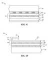
- FIG. 3Billustrates an embodiment of a support substrate 230 being bonded or otherwise attached to the SSE 202 .
- the support substrate 230can include an optional backside reflective material 220 b .
- the backside reflective material 220 bis bonded or otherwise attached to the reflective material 220 a using an elevated pressure and/or elevated temperature process.
- FIG. 3Cshows an embodiment in which the bonded reflective materials 220 a , 220 b ( FIG. 3B ) form a combined reflective material 220 .
- the epitaxial substrate 210has also been thinned, e.g., by backgrinding. At this point, the remaining epitaxial substrate 210 can be implanted with a p-type dopant (e.g., boron) to form a p-n junction with the underlying silicon or other semiconductor material 216 . In another embodiment, the substrate 210 can be doped in a prior step.
- a p-type dopante.g., boron
- the semiconductor material 216typically includes buffer layers to facilitate forming the SSE 202 , and because the buffer layers typically include undoped, large-bandgap semiconductor layers (e.g., GaN, AlGaN or AlN) the p-n junction will be electrically isolated from the epitaxial junction that forms the SSE 202 .
- the buffer layerstypically include undoped, large-bandgap semiconductor layers (e.g., GaN, AlGaN or AlN) the p-n junction will be electrically isolated from the epitaxial junction that forms the SSE 202 .
- FIG. 3Dillustrates the microelectronic substrate 300 after backgrinding, after the substrate 300 has been inverted, and after the epitaxial substrate 210 has been doped.
- Most of the semiconductor material 216 and the epitaxial substrate 210have been removed using grinding, etching, and/or other processes to expose an outer surface 209 of the second semiconductor material 208 or other portions of the SSE 202 .
- a portion of the semiconductor material 216 and the epitaxial substrate 210remain on the SSE 202 to form the electrostatic discharge device 250 .
- Thisis one manner in which the electrostatic discharge device 250 can be made integral with the SSE 202 and the SSL 300 .
- the same or similar techniquescan be used to form multiple electrostatic discharge devices 250 integral with the SSE 202 e.g., after the surface 209 has been selectively etched or otherwise treated.
- FIG. 3Eillustrates the microelectronic substrate 300 after a via 240 has been formed through the electrostatic discharge device 250 and a portion the SSE 202 .
- the via 240can be formed by drilling, etching, or other techniques known in the semiconductor fabrication arts.
- the via 240includes sidewalls 241 and provides access to the reflective material 220 which is in electrical communication with the first semiconductor material 204 . In other embodiments, the via 240 provides access to the conductive material 221 , which is in direct electrical contact with the first semiconductor material 204 .
- FIG. 3Fshows the microelectronic substrate 300 after a first insulator 242 has been deposited or formed in the via 240 and the second insulator 244 has been deposited or formed on a lateral sidewall of the electrostatic discharge device 250 .
- FIG. 3Gshows the microelectronic substrate 300 after conductive material has been deposited or formed in the via 240 inward of the first insulator 242 , and the first contact 246 has been formed.
- the first contact 246can comprise silver (Ag), gold (Au), gold-tin (AuSn), silver-tin (AgSn), copper (Cu), aluminum (Al), and/or other conductive materials.
- the first contact 246is insulated from the semiconductor material 216 and the SSE 202 by the first insulator 242 .
- the second contact 248has been deposited or otherwise disposed or formed on the outer surface 209 of the SSE 202 and on the epitaxial substrate 210 of the electrostatic discharge device 250 .
- the second insulator 244insulates the second contact 248 from the semiconductor material 216 .
- a lens(not shown in FIG. 3G ) can be formed over the SSE 202 .
- the lenscan include a light-transmissive material made from silicone, polymethylmethacrylate (PMMA), resin, or other materials with suitable properties for transmitting the radiation emitted by the SSE 202 .
- the lenscan be positioned over the SSE 202 such that light emitted by the SSE 202 and reflected by the reflective material 220 passes through the lens.
- the lenscan include various optical features, such as a curved shape, to diffract or otherwise change the direction of light emitted by the SSE 202 as it exits the lens.
- FIG. 4is a cross-sectional view of an SSL device 400 having an electrostatic discharge device 450 configured in accordance with further embodiments of the present technology.
- the SSL device 400can have several features generally similar to those described above with reference to FIGS. 2-3G .
- the SSL device 400can include an SSE 202 that in turn includes a first semiconductor material 204 (e.g., a p-type material), a second semiconductor material 208 (e.g., an n-type material), and an active region 206 between the first and second semiconductor materials 204 , 208 .
- the SSL device 400can further include a reflective material 220 between the support substrate 230 and the SSE 202 .
- the SSE 202 and the reflective/conductive material 220are formed on an epitaxial substrate 210 (shown in dashed lines in FIG. 4 ).
- the structures that form the electrostatic discharge device 450 and that electrically connect the electrostatic discharge device 450 to the SSEcan be formed on the SSE 202 while the SSE 202 is supported by the epitaxial substrate 210 .
- the epitaxial substrate 210can then be removed.
- the electrostatic discharge device 450is fabricated on the SSE 202 , and both the SSE 202 and the electrostatic discharge device 450 are carried by the substrate 230 , with the electrostatic discharge device 450 positioned between the substrate 230 and the SSE 202 .
- the fabrication steps for forming the electrostatic discharge device 450are performed while the SSE 202 is inverted from the orientation shown in FIG. 4 , and before the substrate 230 is attached.
- the electrostatic discharge device 450can include a plurality of electrostatic junctions 460 (identified individually as first-third junctions 460 a - 460 c ).
- Each electrostatic junction 460can include a first conductive material 454 (identified individually by reference numbers 454 a - 454 c ), an intermediate material 456 (identified individually by reference numbers 456 a - 456 c ), and a second conductive material 458 (identified individually by reference numbers 458 a - 458 c ).
- the materialscan be disposed using any of a variety of suitable deposition, masking, and/or etching processes. These materials can be different than the materials forming the SSE 202 because they are not required to perform a light emitting function.
- the intermediate material 456can have electrical properties different than those of the first conductive material 454 and the second conductive material 458 .
- the intermediate material 456can be a semiconductor (e.g., amorphous silicon) or a metal.
- the first conductive material 454 a of one junctione.g., the first junction 460 a
- the second conductive material 458 b of an adjacent junctione.g., the second junction 460 b
- the illustrated electrostatic discharge device 450includes three junctions 460 placed in series, in further embodiments more or fewer junctions 460 can be used.
- the junctions 460can be altered in size, and/or multiple junctions 460 can be arranged in parallel.
- the electrostatic discharge deviceas a diode.
- the electrostatic discharge devicecan include a different, non-linear circuit element.
- the electrostatic discharge devicecan be constructed and connected to protect the SSE from large reverse voltages, as discussed above in particular embodiments.
- the electrostatic discharge devicecan be connected with a forward bias to prevent the SSE from large forward voltages.
- the SSEcan be connected to both types of ESD devices, to protect against both high forward and high reverse voltages.
Landscapes
- Engineering & Computer Science (AREA)
- Power Engineering (AREA)
- Physics & Mathematics (AREA)
- Condensed Matter Physics & Semiconductors (AREA)
- General Physics & Mathematics (AREA)
- Computer Hardware Design (AREA)
- Microelectronics & Electronic Packaging (AREA)
- Led Devices (AREA)
- Led Device Packages (AREA)
- Semiconductor Lasers (AREA)
- Elimination Of Static Electricity (AREA)
- Semiconductor Integrated Circuits (AREA)
Abstract
Description
Claims (16)
Priority Applications (16)
| Application Number | Priority Date | Filing Date | Title |
|---|---|---|---|
| US13/223,098US8809897B2 (en) | 2011-08-31 | 2011-08-31 | Solid state transducer devices, including devices having integrated electrostatic discharge protection, and associated systems and methods |
| JP2014528429AJP6109174B2 (en) | 2011-08-31 | 2012-08-15 | Solid-state conversion device including device with integrated electrostatic discharge protection, and related systems and methods |
| SG11201400191QASG11201400191QA (en) | 2011-08-31 | 2012-08-15 | Solid state transducer devices, including devices having integrated electrostatic discharge protection, and associated systems and methods |
| CN201280042001.1ACN103765586B (en) | 2011-08-31 | 2012-08-15 | Comprise the solid state transducer device of the device with integrated form electrostatic discharge (ESD) protection and associated system and method |
| PCT/US2012/050866WO2013032701A2 (en) | 2011-08-31 | 2012-08-15 | Solid state transducer devices, including devices having integrated electrostatic discharge protection, and associated systems and methods |
| EP12827519.5AEP2751838B1 (en) | 2011-08-31 | 2012-08-15 | Solid state transducer devices having integrated electrostatic discharge protection, and associated method of forming said solid state transducer device. |
| KR1020147006476AKR101675652B1 (en) | 2011-08-31 | 2012-08-15 | Solid state transducer devices, including devices having integrated electrostatic discharge protection, and associated systems and methods |
| TW101130698ATWI493678B (en) | 2011-08-31 | 2012-08-23 | Solid state sensing device with integrated electrostatic discharge protection device and related system and method |
| US14/460,297US9373661B2 (en) | 2011-08-31 | 2014-08-14 | Solid state transducer devices, including devices having integrated electrostatic discharge protection, and associated systems and methods |
| US15/187,022US9978807B2 (en) | 2011-08-31 | 2016-06-20 | Solid state transducer devices, including devices having integrated electrostatic discharge protection, and associated systems and methods |
| US15/976,805US10361245B2 (en) | 2011-08-31 | 2018-05-10 | Solid state transducer devices, including devices having integrated electrostatic discharge protection, and associated systems and methods |
| US16/440,720US10615221B2 (en) | 2011-08-31 | 2019-06-13 | Solid state transducer devices, including devices having integrated electrostatic discharge protection, and associated systems and methods |
| US16/800,287US11195876B2 (en) | 2011-08-31 | 2020-02-25 | Solid state transducer devices, including devices having integrated electrostatic discharge protection, and associated systems and methods |
| US17/539,528US11688758B2 (en) | 2011-08-31 | 2021-12-01 | Solid state transducer devices, including devices having integrated electrostatic discharge protection, and associated systems and methods |
| US18/313,638US12113092B2 (en) | 2011-08-31 | 2023-05-08 | Solid state transducer devices, including devices having integrated electrostatic discharge protection, and associated systems and methods |
| US18/908,037US20250031510A1 (en) | 2011-08-31 | 2024-10-07 | Solid state transducer devices, including devices having integrated electrostatic discharge protection, and associated systems and methods |
Applications Claiming Priority (1)
| Application Number | Priority Date | Filing Date | Title |
|---|---|---|---|
| US13/223,098US8809897B2 (en) | 2011-08-31 | 2011-08-31 | Solid state transducer devices, including devices having integrated electrostatic discharge protection, and associated systems and methods |
Related Child Applications (1)
| Application Number | Title | Priority Date | Filing Date |
|---|---|---|---|
| US14/460,297DivisionUS9373661B2 (en) | 2011-08-31 | 2014-08-14 | Solid state transducer devices, including devices having integrated electrostatic discharge protection, and associated systems and methods |
Publications (2)
| Publication Number | Publication Date |
|---|---|
| US20130049059A1 US20130049059A1 (en) | 2013-02-28 |
| US8809897B2true US8809897B2 (en) | 2014-08-19 |
Family
ID=47742375
Family Applications (9)
| Application Number | Title | Priority Date | Filing Date |
|---|---|---|---|
| US13/223,098Active2031-11-25US8809897B2 (en) | 2011-08-31 | 2011-08-31 | Solid state transducer devices, including devices having integrated electrostatic discharge protection, and associated systems and methods |
| US14/460,297ActiveUS9373661B2 (en) | 2011-08-31 | 2014-08-14 | Solid state transducer devices, including devices having integrated electrostatic discharge protection, and associated systems and methods |
| US15/187,022ActiveUS9978807B2 (en) | 2011-08-31 | 2016-06-20 | Solid state transducer devices, including devices having integrated electrostatic discharge protection, and associated systems and methods |
| US15/976,805ActiveUS10361245B2 (en) | 2011-08-31 | 2018-05-10 | Solid state transducer devices, including devices having integrated electrostatic discharge protection, and associated systems and methods |
| US16/440,720ActiveUS10615221B2 (en) | 2011-08-31 | 2019-06-13 | Solid state transducer devices, including devices having integrated electrostatic discharge protection, and associated systems and methods |
| US16/800,287ActiveUS11195876B2 (en) | 2011-08-31 | 2020-02-25 | Solid state transducer devices, including devices having integrated electrostatic discharge protection, and associated systems and methods |
| US17/539,528ActiveUS11688758B2 (en) | 2011-08-31 | 2021-12-01 | Solid state transducer devices, including devices having integrated electrostatic discharge protection, and associated systems and methods |
| US18/313,638ActiveUS12113092B2 (en) | 2011-08-31 | 2023-05-08 | Solid state transducer devices, including devices having integrated electrostatic discharge protection, and associated systems and methods |
| US18/908,037PendingUS20250031510A1 (en) | 2011-08-31 | 2024-10-07 | Solid state transducer devices, including devices having integrated electrostatic discharge protection, and associated systems and methods |
Family Applications After (8)
| Application Number | Title | Priority Date | Filing Date |
|---|---|---|---|
| US14/460,297ActiveUS9373661B2 (en) | 2011-08-31 | 2014-08-14 | Solid state transducer devices, including devices having integrated electrostatic discharge protection, and associated systems and methods |
| US15/187,022ActiveUS9978807B2 (en) | 2011-08-31 | 2016-06-20 | Solid state transducer devices, including devices having integrated electrostatic discharge protection, and associated systems and methods |
| US15/976,805ActiveUS10361245B2 (en) | 2011-08-31 | 2018-05-10 | Solid state transducer devices, including devices having integrated electrostatic discharge protection, and associated systems and methods |
| US16/440,720ActiveUS10615221B2 (en) | 2011-08-31 | 2019-06-13 | Solid state transducer devices, including devices having integrated electrostatic discharge protection, and associated systems and methods |
| US16/800,287ActiveUS11195876B2 (en) | 2011-08-31 | 2020-02-25 | Solid state transducer devices, including devices having integrated electrostatic discharge protection, and associated systems and methods |
| US17/539,528ActiveUS11688758B2 (en) | 2011-08-31 | 2021-12-01 | Solid state transducer devices, including devices having integrated electrostatic discharge protection, and associated systems and methods |
| US18/313,638ActiveUS12113092B2 (en) | 2011-08-31 | 2023-05-08 | Solid state transducer devices, including devices having integrated electrostatic discharge protection, and associated systems and methods |
| US18/908,037PendingUS20250031510A1 (en) | 2011-08-31 | 2024-10-07 | Solid state transducer devices, including devices having integrated electrostatic discharge protection, and associated systems and methods |
Country Status (8)
| Country | Link |
|---|---|
| US (9) | US8809897B2 (en) |
| EP (1) | EP2751838B1 (en) |
| JP (1) | JP6109174B2 (en) |
| KR (1) | KR101675652B1 (en) |
| CN (1) | CN103765586B (en) |
| SG (1) | SG11201400191QA (en) |
| TW (1) | TWI493678B (en) |
| WO (1) | WO2013032701A2 (en) |
Cited By (4)
| Publication number | Priority date | Publication date | Assignee | Title |
|---|---|---|---|---|
| US20160343912A1 (en)* | 2012-01-05 | 2016-11-24 | Micron Technology, Inc. | Solid-state radiation transducer devices having at least partially transparent buried-contact elements, and associated systems and methods |
| US10361245B2 (en) | 2011-08-31 | 2019-07-23 | Micron Technology, Inc. | Solid state transducer devices, including devices having integrated electrostatic discharge protection, and associated systems and methods |
| US20210036052A1 (en)* | 2011-12-01 | 2021-02-04 | Micron Technology, Inc. | Solid state transducer devices with separately controlled regions, and associated systems and methods |
| US10937776B2 (en) | 2011-08-31 | 2021-03-02 | Micron Technology, Inc. | Solid state transducers with state detection, and associated systems and methods |
Families Citing this family (11)
| Publication number | Priority date | Publication date | Assignee | Title |
|---|---|---|---|---|
| US9450152B2 (en) | 2012-05-29 | 2016-09-20 | Micron Technology, Inc. | Solid state transducer dies having reflective features over contacts and associated systems and methods |
| KR102085897B1 (en)* | 2013-06-10 | 2020-03-06 | 엘지이노텍 주식회사 | Light emitting device and light emitting device package |
| US9653647B2 (en)* | 2013-06-14 | 2017-05-16 | Micron Technology, Inc. | Ultrathin solid state dies and methods of manufacturing the same |
| DE102014105188A1 (en)* | 2014-04-11 | 2015-10-15 | Osram Opto Semiconductors Gmbh | Semiconductor chip, optoelectronic component with semiconductor chip and method for producing a semiconductor chip |
| DE102015116970A1 (en)* | 2015-10-06 | 2017-04-06 | Osram Opto Semiconductors Gmbh | Semiconductor laser and method for producing a semiconductor laser |
| US10784398B2 (en) | 2015-12-24 | 2020-09-22 | Vuereal Inc. | Vertical solid state devices |
| DE102016125430A1 (en)* | 2016-12-22 | 2018-06-28 | Osram Opto Semiconductors Gmbh | Surface-mountable semiconductor laser, arrangement with such a semiconductor laser and operating method therefor |
| US11600743B2 (en) | 2017-03-30 | 2023-03-07 | Vuereal Inc. | High efficient microdevices |
| WO2018178951A1 (en) | 2017-03-30 | 2018-10-04 | Vuereal Inc. | Vertical solid-state devices |
| US11721784B2 (en) | 2017-03-30 | 2023-08-08 | Vuereal Inc. | High efficient micro devices |
| EP4002459A1 (en)* | 2020-11-23 | 2022-05-25 | Infineon Technologies AG | Method for manufacturing an electrostatic discharge protection circuit and electrostatic discharge protection circuit |
Citations (14)
| Publication number | Priority date | Publication date | Assignee | Title |
|---|---|---|---|---|
| US3851291A (en) | 1974-01-17 | 1974-11-26 | Ceramic Magnetics Inc | Thin film thermistor |
| US5216404A (en) | 1990-07-25 | 1993-06-01 | Matsushita Electric Industrial Co., Ltd. | Sic thin-film thermistor |
| US5914501A (en) | 1998-08-27 | 1999-06-22 | Hewlett-Packard Company | Light emitting diode assembly having integrated electrostatic discharge protection |
| US5917534A (en) | 1995-06-29 | 1999-06-29 | Eastman Kodak Company | Light-emitting diode arrays with integrated photodetectors formed as a monolithic device and methods and apparatus for using same |
| US20060006404A1 (en) | 2004-06-30 | 2006-01-12 | James Ibbetson | Chip-scale methods for packaging light emitting devices and chip-scale packaged light emitting devices |
| US7064353B2 (en) | 2004-05-26 | 2006-06-20 | Philips Lumileds Lighting Company, Llc | LED chip with integrated fast switching diode for ESD protection |
| US7528422B2 (en) | 2006-01-20 | 2009-05-05 | Hymite A/S | Package for a light emitting element with integrated electrostatic discharge protection |
| US7589350B2 (en) | 2005-09-29 | 2009-09-15 | Formosa Epitaxy Incorporation | Light-emitting diode chip |
| US7649208B2 (en) | 2005-02-25 | 2010-01-19 | Samsung Electro-Mechanics Co., Ltd. | Light emitting diode package including monitoring photodiode |
| US20100019264A1 (en) | 2008-07-24 | 2010-01-28 | Hwan Hee Jeong | Semiconductor light emitting device |
| US7683383B2 (en) | 2004-10-08 | 2010-03-23 | Epistar Corporation | Light emitting device having circuit protection unit |
| US7714348B2 (en) | 2006-10-06 | 2010-05-11 | Ac-Led Lighting, L.L.C. | AC/DC light emitting diodes with integrated protection mechanism |
| US20100207127A1 (en) | 2009-02-18 | 2010-08-19 | Silitek Electronic (Guangzhou) Co., Ltd. | Light emitting diode with a temperature detecting pattern and manufacturing method thereof |
| US20100295087A1 (en) | 2007-01-16 | 2010-11-25 | Korea Photonics Technology Institute | Light Emitting Diode with High Electrostatic Discharge and Fabrication Method Thereof |
Family Cites Families (66)
| Publication number | Priority date | Publication date | Assignee | Title |
|---|---|---|---|---|
| US4588883A (en) | 1983-11-18 | 1986-05-13 | Eastman Kodak Company | Monolithic devices formed with an array of light emitting diodes and a detector |
| JP2597975B2 (en) | 1985-03-26 | 1997-04-09 | 株式会社東芝 | Semiconductor light emitting device and method of manufacturing the same |
| US4766471A (en) | 1986-01-23 | 1988-08-23 | Energy Conversion Devices, Inc. | Thin film electro-optical devices |
| JPS62188386A (en) | 1986-02-14 | 1987-08-17 | Omron Tateisi Electronics Co | Semiconductor light-emitting element |
| JPS62188386U (en) | 1986-05-22 | 1987-11-30 | ||
| JP2670052B2 (en) | 1987-08-24 | 1997-10-29 | 株式会社日立製作所 | Energy extraction device |
| US5140152A (en) | 1991-05-31 | 1992-08-18 | The University Of Colorado Foundation, Inc. | Full duplex optoelectronic device with integral emitter/detector pair |
| JPH08162669A (en) | 1994-12-06 | 1996-06-21 | Nippondenso Co Ltd | Superluminescent diode |
| US5604136A (en) | 1995-05-26 | 1997-02-18 | National Science Council | Method of manufacturing light converter with amorphous-silicon pin heterojunction diode |
| US6784413B2 (en) | 1998-03-12 | 2004-08-31 | Casio Computer Co., Ltd. | Reading apparatus for reading fingerprint |
| JP2003524815A (en) | 1999-03-02 | 2003-08-19 | クイックスター インヴェストメンツ,インコーポレイテッド | E-commerce in marketing systems, including membership purchase opportunities |
| US6421648B1 (en) | 1999-04-14 | 2002-07-16 | Louis Gagnon | Data processing system for the management of a differential continuous compensation plan |
| US7774229B1 (en) | 1999-08-09 | 2010-08-10 | R-Coupon.Com, Inc. | Methods of anti-spam marketing through personalized referrals and rewards |
| US20010025253A1 (en) | 2000-02-08 | 2001-09-27 | Massmedium. Com | Multi-level award program |
| US6597715B2 (en) | 2000-03-01 | 2003-07-22 | Fuji Xerox Co., Ltd. | Semiconductor laser, optical head, optical disk apparatus and semiconductor laser manufacturing method |
| TW488088B (en) | 2001-01-19 | 2002-05-21 | South Epitaxy Corp | Light emitting diode structure |
| US7038242B2 (en) | 2001-02-28 | 2006-05-02 | Agilent Technologies, Inc. | Amorphous semiconductor open base phototransistor array |
| US20020198779A1 (en) | 2001-06-22 | 2002-12-26 | Michael Rowen | System and method for awarding participants in a marketing plan |
| US7809641B2 (en) | 2001-07-26 | 2010-10-05 | Jpmorgan Chase Bank, National Association | System and method for funding a collective account |
| JP4574118B2 (en) | 2003-02-12 | 2010-11-04 | 株式会社半導体エネルギー研究所 | Semiconductor device and manufacturing method thereof |
| US20040188696A1 (en) | 2003-03-28 | 2004-09-30 | Gelcore, Llc | LED power package |
| US7183727B2 (en) | 2003-09-23 | 2007-02-27 | Microsemi Corporation | Optical and temperature feedbacks to control display brightness |
| EP1687879B1 (en)* | 2003-11-28 | 2008-12-10 | OSRAM Opto Semiconductors GmbH | Light-emitting semiconductor component comprising a protective diode |
| DE102004005269B4 (en)* | 2003-11-28 | 2005-09-29 | Osram Opto Semiconductors Gmbh | Light emitting semiconductor element has multilayers on a substrate with the pn junction insulatively separated into light emitting and protective diode sections |
| US7795934B2 (en) | 2003-12-11 | 2010-09-14 | Micron Technology, Inc. | Switched capacitor for a tunable delay circuit |
| JP2006086300A (en)* | 2004-09-15 | 2006-03-30 | Sanken Electric Co Ltd | Semiconductor light emitting device having protective element and manufacturing method thereof |
| JP4019285B2 (en) | 2005-02-04 | 2007-12-12 | セイコーエプソン株式会社 | Surface emitting device and method for manufacturing the same |
| JP4697397B2 (en) | 2005-02-16 | 2011-06-08 | サンケン電気株式会社 | Composite semiconductor device |
| EP1880585A1 (en) | 2005-03-03 | 2008-01-23 | Tir Systems Ltd. | Method and apparatus for controlling thermal stress in lighting devices |
| US7706421B2 (en) | 2005-04-20 | 2010-04-27 | Finisar Corporation | Temperature sensing device patterned on an electro-optic transducer die |
| JP2006339629A (en)* | 2005-05-02 | 2006-12-14 | Nichia Chem Ind Ltd | Semiconductor element |
| JP4650631B2 (en) | 2005-11-30 | 2011-03-16 | ソニー株式会社 | Semiconductor light emitting device |
| JP4978014B2 (en)* | 2006-01-30 | 2012-07-18 | サンケン電気株式会社 | Semiconductor light emitting device and manufacturing method thereof |
| US20070185766A1 (en) | 2006-02-07 | 2007-08-09 | I.S.E.C. Holdings Ltd. | System encouraging website visitors to recommend the site |
| US8041343B2 (en) | 2006-02-23 | 2011-10-18 | Qualcomm Incorporated | Apparatus and methods for incentivized superdistribution of content |
| US7994514B2 (en)* | 2006-04-21 | 2011-08-09 | Koninklijke Philips Electronics N.V. | Semiconductor light emitting device with integrated electronic components |
| JP5044986B2 (en)* | 2006-05-17 | 2012-10-10 | サンケン電気株式会社 | Semiconductor light emitting device |
| JP4539615B2 (en) | 2006-07-28 | 2010-09-08 | 株式会社日立製作所 | Recording strategy determination method, optical disc recording method, optical disc, and optical disc apparatus |
| DE102006046038A1 (en) | 2006-09-28 | 2008-04-03 | Osram Opto Semiconductors Gmbh | LED semiconductor body for e.g. vehicle lighting, has radiation-generating active layers adjusted to operating voltage such that voltage dropping at series resistor is larger as voltage dropping at semiconductor body |
| KR20080089859A (en) | 2007-04-02 | 2008-10-08 | 엘지이노텍 주식회사 | Nitride semiconductor light emitting device and manufacturing method thereof |
| JP4983346B2 (en) | 2007-04-02 | 2012-07-25 | ソニー株式会社 | Semiconductor light emitting device |
| US7985970B2 (en) | 2009-04-06 | 2011-07-26 | Cree, Inc. | High voltage low current surface-emitting LED |
| US20090157497A1 (en) | 2007-12-14 | 2009-06-18 | Fusz Eugene A | Systems and methods for generating revenue from social interaction |
| US20100070364A1 (en) | 2008-02-28 | 2010-03-18 | James Michael Dugan | PipPops - Partners In Profit Point Of Purchase Savings System |
| KR101449035B1 (en) | 2008-04-30 | 2014-10-08 | 엘지이노텍 주식회사 | Semiconductor light emitting device |
| DE102008025159A1 (en) | 2008-05-26 | 2009-12-10 | Osram Opto Semiconductors Gmbh | Semiconductor device, reflected light barrier and method for producing a housing |
| DE102008034560B4 (en)* | 2008-07-24 | 2022-10-27 | OSRAM Opto Semiconductors Gesellschaft mit beschränkter Haftung | Radiation-emitting semiconductor chip and method for producing a radiation-emitting semiconductor chip |
| JP2010053021A (en)* | 2008-07-28 | 2010-03-11 | Ngk Insulators Ltd | Piezoelectric/electrostrictive ceramic sintered body and method of calculating diffuse scattering intensity ratio |
| KR101592201B1 (en) | 2008-11-06 | 2016-02-05 | 삼성전자 주식회사 | Light emitting device and fabricating method thereof |
| DE102009006177A1 (en)* | 2008-11-28 | 2010-06-02 | Osram Opto Semiconductors Gmbh | Radiation-emitting semiconductor chip |
| WO2010099647A1 (en) | 2009-03-02 | 2010-09-10 | Hong Kong Applied Science And Technology Research Institute Co., Ltd. | Light emitting device package for temperature detection |
| US20120049214A1 (en) | 2009-04-06 | 2012-03-01 | Lowes Theodore D | Monolithic Multi-Junction Light Emitting Devices Including Multiple Groups of Light Emitting Diodes |
| TWI447892B (en) | 2009-04-20 | 2014-08-01 | Ind Tech Res Inst | Light emitting device and manufacturing method thereof |
| KR20100011116U (en) | 2009-05-06 | 2010-11-16 | (주)로얄기공 | A cover of a stack |
| WO2011018942A1 (en) | 2009-08-13 | 2011-02-17 | 昭和電工株式会社 | Semiconductor light-emitting element, semiconductor light-emitting device, method for producing semiconductor light-emitting element, method for producing semiconductor light-emitting device, illumination device using semiconductor light-emitting device, and electronic apparatus |
| US20110131085A1 (en) | 2009-11-30 | 2011-06-02 | Lead Wey | Method, System and Computer Program Product for Advertising Supported Matchmaking Services |
| KR100974787B1 (en)* | 2010-02-04 | 2010-08-06 | 엘지이노텍 주식회사 | Light emitting device, method for fabricating the light emitting device and light emitting device package |
| KR100999692B1 (en)* | 2010-02-18 | 2010-12-08 | 엘지이노텍 주식회사 | Light emitting device, light emitting device manufacturing method and light emitting device package |
| US20130054331A1 (en) | 2010-04-26 | 2013-02-28 | Mutual Tree Atividades De Internet Ltda. | System of distributing commissions within a relationship network |
| US8653542B2 (en) | 2011-01-13 | 2014-02-18 | Tsmc Solid State Lighting Ltd. | Micro-interconnects for light-emitting diodes |
| DE102011011378A1 (en)* | 2011-02-16 | 2012-08-16 | Osram Opto Semiconductors Gmbh | Carrier substrate and method for the production of semiconductor chips |
| US8587018B2 (en)* | 2011-06-24 | 2013-11-19 | Tsmc Solid State Lighting Ltd. | LED structure having embedded zener diode |
| US9490239B2 (en) | 2011-08-31 | 2016-11-08 | Micron Technology, Inc. | Solid state transducers with state detection, and associated systems and methods |
| US8809897B2 (en) | 2011-08-31 | 2014-08-19 | Micron Technology, Inc. | Solid state transducer devices, including devices having integrated electrostatic discharge protection, and associated systems and methods |
| US8441104B1 (en) | 2011-11-16 | 2013-05-14 | Analog Devices, Inc. | Electrical overstress protection using through-silicon-via (TSV) |
| JP5960426B2 (en) | 2011-12-16 | 2016-08-02 | スタンレー電気株式会社 | Semiconductor device and method for manufacturing semiconductor device |
- 2011
- 2011-08-31USUS13/223,098patent/US8809897B2/enactiveActive
- 2012
- 2012-08-15CNCN201280042001.1Apatent/CN103765586B/enactiveActive
- 2012-08-15JPJP2014528429Apatent/JP6109174B2/enactiveActive
- 2012-08-15KRKR1020147006476Apatent/KR101675652B1/enactiveActive
- 2012-08-15EPEP12827519.5Apatent/EP2751838B1/enactiveActive
- 2012-08-15SGSG11201400191QApatent/SG11201400191QA/enunknown
- 2012-08-15WOPCT/US2012/050866patent/WO2013032701A2/enactiveApplication Filing
- 2012-08-23TWTW101130698Apatent/TWI493678B/enactive
- 2014
- 2014-08-14USUS14/460,297patent/US9373661B2/enactiveActive
- 2016
- 2016-06-20USUS15/187,022patent/US9978807B2/enactiveActive
- 2018
- 2018-05-10USUS15/976,805patent/US10361245B2/enactiveActive
- 2019
- 2019-06-13USUS16/440,720patent/US10615221B2/enactiveActive
- 2020
- 2020-02-25USUS16/800,287patent/US11195876B2/enactiveActive
- 2021
- 2021-12-01USUS17/539,528patent/US11688758B2/enactiveActive
- 2023
- 2023-05-08USUS18/313,638patent/US12113092B2/enactiveActive
- 2024
- 2024-10-07USUS18/908,037patent/US20250031510A1/enactivePending
Patent Citations (15)
| Publication number | Priority date | Publication date | Assignee | Title |
|---|---|---|---|---|
| US3851291A (en) | 1974-01-17 | 1974-11-26 | Ceramic Magnetics Inc | Thin film thermistor |
| US5216404A (en) | 1990-07-25 | 1993-06-01 | Matsushita Electric Industrial Co., Ltd. | Sic thin-film thermistor |
| US5917534A (en) | 1995-06-29 | 1999-06-29 | Eastman Kodak Company | Light-emitting diode arrays with integrated photodetectors formed as a monolithic device and methods and apparatus for using same |
| US5914501A (en) | 1998-08-27 | 1999-06-22 | Hewlett-Packard Company | Light emitting diode assembly having integrated electrostatic discharge protection |
| US7064353B2 (en) | 2004-05-26 | 2006-06-20 | Philips Lumileds Lighting Company, Llc | LED chip with integrated fast switching diode for ESD protection |
| US20060006404A1 (en) | 2004-06-30 | 2006-01-12 | James Ibbetson | Chip-scale methods for packaging light emitting devices and chip-scale packaged light emitting devices |
| US7683383B2 (en) | 2004-10-08 | 2010-03-23 | Epistar Corporation | Light emitting device having circuit protection unit |
| US7649208B2 (en) | 2005-02-25 | 2010-01-19 | Samsung Electro-Mechanics Co., Ltd. | Light emitting diode package including monitoring photodiode |
| US7589350B2 (en) | 2005-09-29 | 2009-09-15 | Formosa Epitaxy Incorporation | Light-emitting diode chip |
| US7528422B2 (en) | 2006-01-20 | 2009-05-05 | Hymite A/S | Package for a light emitting element with integrated electrostatic discharge protection |
| US7714348B2 (en) | 2006-10-06 | 2010-05-11 | Ac-Led Lighting, L.L.C. | AC/DC light emitting diodes with integrated protection mechanism |
| US20100295087A1 (en) | 2007-01-16 | 2010-11-25 | Korea Photonics Technology Institute | Light Emitting Diode with High Electrostatic Discharge and Fabrication Method Thereof |
| KR20100011116A (en) | 2008-07-24 | 2010-02-03 | 엘지이노텍 주식회사 | Semiconductor light emitting device and fabrication method thereof |
| US20100019264A1 (en) | 2008-07-24 | 2010-01-28 | Hwan Hee Jeong | Semiconductor light emitting device |
| US20100207127A1 (en) | 2009-02-18 | 2010-08-19 | Silitek Electronic (Guangzhou) Co., Ltd. | Light emitting diode with a temperature detecting pattern and manufacturing method thereof |
Non-Patent Citations (26)
| Title |
|---|
| Atwater Jr., H.A., Ion Beam Enhanced Grain Growth in Thin Films, RLE Technical Report No. 527, Massachusetts Institute of Technology, Research Laboratory of Electronics, pp. 1-224, Mar. 1987. |
| Atwater, H.A. et al., Mechanisms for Crystallographic Orientation in the Crystallization of Thin Silicon Films from the Melt, J. Mater. Res., vol. 3, No. 6, pp. 1232-1237, Nov./Dec. 1988. |
| Atwater, H.A. et al., Zone-Melting Recrystallization of Thick Silicon on Insulator Films, Materials Letters, vol. 2, No. 4A, pp. 269-273, Mar. 1984. |
| Bikgi, L. et al., "Integrated Optical Proximity Sensor Based on Organic Photodiodes and organic LEDs", Proc. SPIE 5961, 596104 (2005), doi:10.1117/12.628140. |
| Choi, J.-H. et al. Zone Melting Recrystallization of Polysilicon by a Focused-Lamp with Unsymmetric Trapezoidal Power Distribution, Journal of Electronic Materials, vol. 20, No. 3, pp. 231-235, Mar. 1991. |
| Colinge, J.-P., Silicon-on-Insulator Technology: Materials to VLSI, 2nd Edition, pp. 16-27 and 52-65, Sep. 1997. |
| Geis, M.W. et al., (Invited) Silicon Graphoepitaxy, Proceedings of the 12th Conference on Solid State Devices, Tokyo 1980, Japanese Journal of Applied Physics, vol. 20, Supplement 20-1, pp. 39-42, 1981. |
| Geis, M.W. et al., Grapho-Epitaxy of Silicon on Fused Silica using Surface Micropatterns and Laser Crystallization, J. Vac. Sci. Technol., vol. 16, No. 6, pp. 1640-1643, Nov./Dec. 1979. |
| Geis, M.W. et al., Summary Abstract: Silicon Graphoepitaxy, J. Vac. Sci. Technol., vol. 18, No. 2, pp. 229-230, Mar. 1981. |
| Geis, M.W. et al., Zone-Melting Recrystallization of Si Films with a Moveable-Strip-Heater Oven, J. Electrochem. Soc.: Solid State Science and Technology, vol. 129, No. 12, pp. 2812-2818, Dec. 1982. |
| Givargizov, E.I., Graphoepitaxy as an Approach to Oriented Crystallization on Amorphous Substrates, Journal of Crystal Growth, vol. 310, No. 7-9, pp. 1686-1690, Apr. 2008. |
| International Search Report and Written Opinion issued Feb. 28, 2013 in International Application No. PCT/US2012/050866, 8 pages. |
| Klykov, V.I. et al. Artificial Epitaxy (Diataxy) of Silicon and Germanium, Acta Physica Academiae Scientiarum Hungaricae, vol. 47, Nos. 1-3, pp. 167-183, Mar. 1979. |
| Minagawa, Y. et al. Fabrication of (111)-Oriented Si Film with a Ni/Ti Layer by Metal Induced Crystallization, Jpn. J. Appl. Phys., vol. 20, Part 2, No. 3A, pp. L186-L188, Mar. 2001. |
| Moon, B.Y. et al. Study on the Polycrystalline Silicon Films Deposited by Inductively Coupled Plasma Chemical Vapor Deposition, Mat. Res. Soc. Symp. Proc., vol. 685E, pp. D5.2.1-D5.2.6, 2001. |
| Moridi, M. et al., "An Amorphous Silicon Photodiode Array for Glass-Based Optical MEMS Application", IEEE Sensors 2009, pp. 1604-1608, Oct. 2009, doi:10.1109/ICSENS.2009.5398496. |
| Nanotechweb.org, Nanoparticle Film Turns LED into Portable Ozone Sensor, 2 pages, Oct. 11, 2007, retrieved from the Internet, URL: http://nanotechweb.org/cws/article/tech/31446. |
| Naomoto, H. et al., Characterization of Thin-Film Silicon Formed by High-Speed Zone-Melting Recrystallization Process, Solar Energy Materials and Solar Cells, vol. 48, Nos. 1-4, pp. 261-267, Nov. 1997. |
| Pauli, M. et al., Large Area and Rapid Thermal Zone Melting Crystallization of Silicon Films on Graphite Substrates for Photovoltaic Use, Conference Record of the 23rd IEEE Photovoltaic Specialists Conference, pp. 195-200, May 1993. |
| Sato, Y. et al., "A Method of Preparing Thin-Film Micro-PTC Thermistors Based on BaTiO3 Using YAG-Laser Irradiation", Electronics and Communications in Japan, Part 2, vol. 85, No. 11, pp. 25-31, Nov. 2002, doi:10.1002/ecjb.1113. |
| Scharff, W. et al., Flash-Lamp-Induced Crystal Growth of Silicon on Amorphous Substrates Using Artificial Surface-Relief Structures, Physica Status Solidi (a), vol. 74, No. 2, pp. 545-552, Dec. 1982. |
| Urban, G. et al., "High-Resolution Thin-Film Temperature Sensor Arrays for Medical Applications", Sensors and Actuators A: Physical, vol. 22, Nos. 1-3, pp. 650-654, Jun. 1989, doi:10.1016/0924-4247(89)80051-2. |
| Wan, J. et al., Growth of Crack-Free Hexagonal GaN Films on Si(100), Applied Physics Letters, vol. 79, No. 10, pp. 1459-1461, Sep. 2001. |
| Wang, X.X. et al., "All-Thin-Film GeAu Thermistors for Particle Detection", Journal of Low Temperature Physics, vol. 93, Nos. 3-4, pp. 349-354, Nov. 1993, doi:10.1007/BF00693445. |
| Wronski, C.R. and D.E. Carlson, "Surface States and Barrier Heights of Metal-Amorphous Silicon Schottky Barriers", Solid State Communications, vol. 23, No. 7, pp. 421-424, Aug. 1977, doi:10.1016/0038-1098(77)90999-1. |
| Yoon, S.M. et al., Numerical Simulation of Scanning Speed and Supercooling Effects During Zone-Melting-Recrystallization of SOI Wafers, Mat. Res. Soc. Symp. Proc., vol. 205, pp. 453-458, 1990. |
Cited By (13)
| Publication number | Priority date | Publication date | Assignee | Title |
|---|---|---|---|---|
| US11688758B2 (en) | 2011-08-31 | 2023-06-27 | Micron Technology, Inc. | Solid state transducer devices, including devices having integrated electrostatic discharge protection, and associated systems and methods |
| US10361245B2 (en) | 2011-08-31 | 2019-07-23 | Micron Technology, Inc. | Solid state transducer devices, including devices having integrated electrostatic discharge protection, and associated systems and methods |
| US10615221B2 (en) | 2011-08-31 | 2020-04-07 | Micron Technology, Inc. | Solid state transducer devices, including devices having integrated electrostatic discharge protection, and associated systems and methods |
| US10937776B2 (en) | 2011-08-31 | 2021-03-02 | Micron Technology, Inc. | Solid state transducers with state detection, and associated systems and methods |
| US11195876B2 (en) | 2011-08-31 | 2021-12-07 | Micron Technology, Inc. | Solid state transducer devices, including devices having integrated electrostatic discharge protection, and associated systems and methods |
| US12113092B2 (en) | 2011-08-31 | 2024-10-08 | Micron Technology, Inc. | Solid state transducer devices, including devices having integrated electrostatic discharge protection, and associated systems and methods |
| US12230616B2 (en) | 2011-08-31 | 2025-02-18 | Micron Technology, Inc. | Solid state transducers with state detection, and associated systems and methods |
| US20210036052A1 (en)* | 2011-12-01 | 2021-02-04 | Micron Technology, Inc. | Solid state transducer devices with separately controlled regions, and associated systems and methods |
| US12205975B2 (en)* | 2011-12-01 | 2025-01-21 | Micron Technology, Inc. | Solid state transducer devices with separately controlled regions, and associated systems and methods |
| US9653654B2 (en)* | 2012-01-05 | 2017-05-16 | Micron Technology, Inc. | Solid-state radiation transducer devices having at least partially transparent buried contact elements, and associated systems and methods |
| US10559719B2 (en) | 2012-01-05 | 2020-02-11 | Micron Technology, Inc. | Solid-state radiation transducer devices having at least partially transparent buried-contact elements, and associated systems and methods |
| US11670738B2 (en) | 2012-01-05 | 2023-06-06 | Micron Technology, Inc. | Solid-state radiation transducer devices having at least partially transparent buried-contact elements, and associated systems and methods |
| US20160343912A1 (en)* | 2012-01-05 | 2016-11-24 | Micron Technology, Inc. | Solid-state radiation transducer devices having at least partially transparent buried-contact elements, and associated systems and methods |
Also Published As
| Publication number | Publication date |
|---|---|
| TW201316482A (en) | 2013-04-16 |
| US20150171138A1 (en) | 2015-06-18 |
| US20220165784A1 (en) | 2022-05-26 |
| US10361245B2 (en) | 2019-07-23 |
| US20200194492A1 (en) | 2020-06-18 |
| WO2013032701A2 (en) | 2013-03-07 |
| US10615221B2 (en) | 2020-04-07 |
| US20160372513A1 (en) | 2016-12-22 |
| US20130049059A1 (en) | 2013-02-28 |
| KR20140053306A (en) | 2014-05-07 |
| US11195876B2 (en) | 2021-12-07 |
| SG11201400191QA (en) | 2014-07-30 |
| JP2014525686A (en) | 2014-09-29 |
| EP2751838A2 (en) | 2014-07-09 |
| US20190312081A1 (en) | 2019-10-10 |
| CN103765586A (en) | 2014-04-30 |
| WO2013032701A3 (en) | 2013-07-11 |
| EP2751838B1 (en) | 2024-04-24 |
| US9978807B2 (en) | 2018-05-22 |
| EP2751838A4 (en) | 2015-05-20 |
| US20250031510A1 (en) | 2025-01-23 |
| US9373661B2 (en) | 2016-06-21 |
| US20180261646A1 (en) | 2018-09-13 |
| US12113092B2 (en) | 2024-10-08 |
| CN103765586B (en) | 2016-08-17 |
| JP6109174B2 (en) | 2017-04-05 |
| TWI493678B (en) | 2015-07-21 |
| US20230275113A1 (en) | 2023-08-31 |
| US11688758B2 (en) | 2023-06-27 |
| KR101675652B1 (en) | 2016-11-11 |
Similar Documents
| Publication | Publication Date | Title |
|---|---|---|
| US12113092B2 (en) | Solid state transducer devices, including devices having integrated electrostatic discharge protection, and associated systems and methods | |
| US12230616B2 (en) | Solid state transducers with state detection, and associated systems and methods | |
| US11183486B2 (en) | High voltage solid-state transducers and solid-state transducer arrays having electrical cross-connections and associated systems and methods |
Legal Events
| Date | Code | Title | Description |
|---|---|---|---|
| AS | Assignment | Owner name:MICRON TECHNOLOGY, INC., IDAHO Free format text:ASSIGNMENT OF ASSIGNORS INTEREST;ASSIGNORS:ODNOBLYUDOV, VLADIMIR;SCHUBERT, MARTIN F.;REEL/FRAME:026840/0885 Effective date:20110826 | |
| FEPP | Fee payment procedure | Free format text:PAYOR NUMBER ASSIGNED (ORIGINAL EVENT CODE: ASPN); ENTITY STATUS OF PATENT OWNER: LARGE ENTITY | |
| STCF | Information on status: patent grant | Free format text:PATENTED CASE | |
| CC | Certificate of correction | ||
| AS | Assignment | Owner name:U.S. BANK NATIONAL ASSOCIATION, AS COLLATERAL AGENT, CALIFORNIA Free format text:SECURITY INTEREST;ASSIGNOR:MICRON TECHNOLOGY, INC.;REEL/FRAME:038669/0001 Effective date:20160426 Owner name:U.S. BANK NATIONAL ASSOCIATION, AS COLLATERAL AGEN Free format text:SECURITY INTEREST;ASSIGNOR:MICRON TECHNOLOGY, INC.;REEL/FRAME:038669/0001 Effective date:20160426 | |
| AS | Assignment | Owner name:MORGAN STANLEY SENIOR FUNDING, INC., AS COLLATERAL AGENT, MARYLAND Free format text:PATENT SECURITY AGREEMENT;ASSIGNOR:MICRON TECHNOLOGY, INC.;REEL/FRAME:038954/0001 Effective date:20160426 Owner name:MORGAN STANLEY SENIOR FUNDING, INC., AS COLLATERAL Free format text:PATENT SECURITY AGREEMENT;ASSIGNOR:MICRON TECHNOLOGY, INC.;REEL/FRAME:038954/0001 Effective date:20160426 | |
| AS | Assignment | Owner name:U.S. BANK NATIONAL ASSOCIATION, AS COLLATERAL AGENT, CALIFORNIA Free format text:CORRECTIVE ASSIGNMENT TO CORRECT THE REPLACE ERRONEOUSLY FILED PATENT #7358718 WITH THE CORRECT PATENT #7358178 PREVIOUSLY RECORDED ON REEL 038669 FRAME 0001. ASSIGNOR(S) HEREBY CONFIRMS THE SECURITY INTEREST;ASSIGNOR:MICRON TECHNOLOGY, INC.;REEL/FRAME:043079/0001 Effective date:20160426 Owner name:U.S. BANK NATIONAL ASSOCIATION, AS COLLATERAL AGEN Free format text:CORRECTIVE ASSIGNMENT TO CORRECT THE REPLACE ERRONEOUSLY FILED PATENT #7358718 WITH THE CORRECT PATENT #7358178 PREVIOUSLY RECORDED ON REEL 038669 FRAME 0001. ASSIGNOR(S) HEREBY CONFIRMS THE SECURITY INTEREST;ASSIGNOR:MICRON TECHNOLOGY, INC.;REEL/FRAME:043079/0001 Effective date:20160426 | |
| MAFP | Maintenance fee payment | Free format text:PAYMENT OF MAINTENANCE FEE, 4TH YEAR, LARGE ENTITY (ORIGINAL EVENT CODE: M1551) Year of fee payment:4 | |
| AS | Assignment | Owner name:JPMORGAN CHASE BANK, N.A., AS COLLATERAL AGENT, ILLINOIS Free format text:SECURITY INTEREST;ASSIGNORS:MICRON TECHNOLOGY, INC.;MICRON SEMICONDUCTOR PRODUCTS, INC.;REEL/FRAME:047540/0001 Effective date:20180703 Owner name:JPMORGAN CHASE BANK, N.A., AS COLLATERAL AGENT, IL Free format text:SECURITY INTEREST;ASSIGNORS:MICRON TECHNOLOGY, INC.;MICRON SEMICONDUCTOR PRODUCTS, INC.;REEL/FRAME:047540/0001 Effective date:20180703 | |
| AS | Assignment | Owner name:MICRON TECHNOLOGY, INC., IDAHO Free format text:RELEASE BY SECURED PARTY;ASSIGNOR:U.S. BANK NATIONAL ASSOCIATION, AS COLLATERAL AGENT;REEL/FRAME:047243/0001 Effective date:20180629 | |
| AS | Assignment | Owner name:MICRON TECHNOLOGY, INC., IDAHO Free format text:RELEASE BY SECURED PARTY;ASSIGNOR:MORGAN STANLEY SENIOR FUNDING, INC., AS COLLATERAL AGENT;REEL/FRAME:050937/0001 Effective date:20190731 | |
| AS | Assignment | Owner name:MICRON SEMICONDUCTOR PRODUCTS, INC., IDAHO Free format text:RELEASE BY SECURED PARTY;ASSIGNOR:JPMORGAN CHASE BANK, N.A., AS COLLATERAL AGENT;REEL/FRAME:051028/0001 Effective date:20190731 Owner name:MICRON TECHNOLOGY, INC., IDAHO Free format text:RELEASE BY SECURED PARTY;ASSIGNOR:JPMORGAN CHASE BANK, N.A., AS COLLATERAL AGENT;REEL/FRAME:051028/0001 Effective date:20190731 | |
| MAFP | Maintenance fee payment | Free format text:PAYMENT OF MAINTENANCE FEE, 8TH YEAR, LARGE ENTITY (ORIGINAL EVENT CODE: M1552); ENTITY STATUS OF PATENT OWNER: LARGE ENTITY Year of fee payment:8 |