US8808775B2 - Method and apparatus for cartridge-based carbonation of beverages - Google Patents
Method and apparatus for cartridge-based carbonation of beveragesDownload PDFInfo
- Publication number
- US8808775B2 US8808775B2US13/017,459US201113017459AUS8808775B2US 8808775 B2US8808775 B2US 8808775B2US 201113017459 AUS201113017459 AUS 201113017459AUS 8808775 B2US8808775 B2US 8808775B2
- Authority
- US
- United States
- Prior art keywords
- cartridge
- carbon dioxide
- chamber
- liquid
- beverage
- Prior art date
- Legal status (The legal status is an assumption and is not a legal conclusion. Google has not performed a legal analysis and makes no representation as to the accuracy of the status listed.)
- Expired - Fee Related, expires
Links
Images


Classifications
- B—PERFORMING OPERATIONS; TRANSPORTING
- B67—OPENING, CLOSING OR CLEANING BOTTLES, JARS OR SIMILAR CONTAINERS; LIQUID HANDLING
- B67D—DISPENSING, DELIVERING OR TRANSFERRING LIQUIDS, NOT OTHERWISE PROVIDED FOR
- B67D1/00—Apparatus or devices for dispensing beverages on draught
- B67D1/04—Apparatus utilising compressed air or other gas acting directly or indirectly on beverages in storage containers
- B67D1/0406—Apparatus utilising compressed air or other gas acting directly or indirectly on beverages in storage containers with means for carbonating the beverage, or for maintaining its carbonation
- A—HUMAN NECESSITIES
- A23—FOODS OR FOODSTUFFS; TREATMENT THEREOF, NOT COVERED BY OTHER CLASSES
- A23L—FOODS, FOODSTUFFS OR NON-ALCOHOLIC BEVERAGES, NOT OTHERWISE PROVIDED FOR; PREPARATION OR TREATMENT THEREOF
- A23L2/00—Non-alcoholic beverages; Dry compositions or concentrates therefor; Preparation or treatment thereof
- A23L2/40—Effervescence-generating compositions
- A—HUMAN NECESSITIES
- A23—FOODS OR FOODSTUFFS; TREATMENT THEREOF, NOT COVERED BY OTHER CLASSES
- A23L—FOODS, FOODSTUFFS OR NON-ALCOHOLIC BEVERAGES, NOT OTHERWISE PROVIDED FOR; PREPARATION OR TREATMENT THEREOF
- A23L2/00—Non-alcoholic beverages; Dry compositions or concentrates therefor; Preparation or treatment thereof
- A23L2/52—Adding ingredients
- A23L2/54—Mixing with gases
- A—HUMAN NECESSITIES
- A47—FURNITURE; DOMESTIC ARTICLES OR APPLIANCES; COFFEE MILLS; SPICE MILLS; SUCTION CLEANERS IN GENERAL
- A47J—KITCHEN EQUIPMENT; COFFEE MILLS; SPICE MILLS; APPARATUS FOR MAKING BEVERAGES
- A47J31/00—Apparatus for making beverages
- A—HUMAN NECESSITIES
- A47—FURNITURE; DOMESTIC ARTICLES OR APPLIANCES; COFFEE MILLS; SPICE MILLS; SUCTION CLEANERS IN GENERAL
- A47J—KITCHEN EQUIPMENT; COFFEE MILLS; SPICE MILLS; APPARATUS FOR MAKING BEVERAGES
- A47J31/00—Apparatus for making beverages
- A47J31/40—Beverage-making apparatus with dispensing means for adding a measured quantity of ingredients, e.g. coffee, water, sugar, cocoa, milk, tea
- A47J31/407—Beverage-making apparatus with dispensing means for adding a measured quantity of ingredients, e.g. coffee, water, sugar, cocoa, milk, tea with ingredient-containing cartridges; Cartridge-perforating means
- A—HUMAN NECESSITIES
- A47—FURNITURE; DOMESTIC ARTICLES OR APPLIANCES; COFFEE MILLS; SPICE MILLS; SUCTION CLEANERS IN GENERAL
- A47J—KITCHEN EQUIPMENT; COFFEE MILLS; SPICE MILLS; APPARATUS FOR MAKING BEVERAGES
- A47J31/00—Apparatus for making beverages
- A47J31/40—Beverage-making apparatus with dispensing means for adding a measured quantity of ingredients, e.g. coffee, water, sugar, cocoa, milk, tea
- A47J31/41—Beverage-making apparatus with dispensing means for adding a measured quantity of ingredients, e.g. coffee, water, sugar, cocoa, milk, tea of liquid ingredients
- A—HUMAN NECESSITIES
- A47—FURNITURE; DOMESTIC ARTICLES OR APPLIANCES; COFFEE MILLS; SPICE MILLS; SUCTION CLEANERS IN GENERAL
- A47J—KITCHEN EQUIPMENT; COFFEE MILLS; SPICE MILLS; APPARATUS FOR MAKING BEVERAGES
- A47J31/00—Apparatus for making beverages
- A47J31/44—Parts or details or accessories of beverage-making apparatus
- B01F15/0205—
- B01F15/0206—
- B—PERFORMING OPERATIONS; TRANSPORTING
- B01—PHYSICAL OR CHEMICAL PROCESSES OR APPARATUS IN GENERAL
- B01F—MIXING, e.g. DISSOLVING, EMULSIFYING OR DISPERSING
- B01F23/00—Mixing according to the phases to be mixed, e.g. dispersing or emulsifying
- B01F23/20—Mixing gases with liquids
- B—PERFORMING OPERATIONS; TRANSPORTING
- B01—PHYSICAL OR CHEMICAL PROCESSES OR APPARATUS IN GENERAL
- B01F—MIXING, e.g. DISSOLVING, EMULSIFYING OR DISPERSING
- B01F23/00—Mixing according to the phases to be mixed, e.g. dispersing or emulsifying
- B01F23/20—Mixing gases with liquids
- B01F23/23—Mixing gases with liquids by introducing gases into liquid media, e.g. for producing aerated liquids
- B01F23/236—Mixing gases with liquids by introducing gases into liquid media, e.g. for producing aerated liquids specially adapted for aerating or carbonating beverages
- B01F23/2362—Mixing gases with liquids by introducing gases into liquid media, e.g. for producing aerated liquids specially adapted for aerating or carbonating beverages for aerating or carbonating within receptacles or tanks, e.g. distribution machines
- B01F3/04808—
- B—PERFORMING OPERATIONS; TRANSPORTING
- B01—PHYSICAL OR CHEMICAL PROCESSES OR APPARATUS IN GENERAL
- B01F—MIXING, e.g. DISSOLVING, EMULSIFYING OR DISPERSING
- B01F35/00—Accessories for mixers; Auxiliary operations or auxiliary devices; Parts or details of general application
- B01F35/71—Feed mechanisms
- B01F35/713—Feed mechanisms comprising breaking packages or parts thereof, e.g. piercing or opening sealing elements between compartments or cartridges
- B01F35/7131—Breaking or perforating packages, containers or vials
- B—PERFORMING OPERATIONS; TRANSPORTING
- B65—CONVEYING; PACKING; STORING; HANDLING THIN OR FILAMENTARY MATERIAL
- B65D—CONTAINERS FOR STORAGE OR TRANSPORT OF ARTICLES OR MATERIALS, e.g. BAGS, BARRELS, BOTTLES, BOXES, CANS, CARTONS, CRATES, DRUMS, JARS, TANKS, HOPPERS, FORWARDING CONTAINERS; ACCESSORIES, CLOSURES, OR FITTINGS THEREFOR; PACKAGING ELEMENTS; PACKAGES
- B65D85/00—Containers, packaging elements or packages, specially adapted for particular articles or materials
- B65D85/70—Containers, packaging elements or packages, specially adapted for particular articles or materials for materials not otherwise provided for
- B65D85/804—Disposable containers or packages with contents which are mixed, infused or dissolved in situ, i.e. without having been previously removed from the package
- B65D85/8043—Packages adapted to allow liquid to pass through the contents
- B65D85/8049—Details of the inlet
- B—PERFORMING OPERATIONS; TRANSPORTING
- B65—CONVEYING; PACKING; STORING; HANDLING THIN OR FILAMENTARY MATERIAL
- B65D—CONTAINERS FOR STORAGE OR TRANSPORT OF ARTICLES OR MATERIALS, e.g. BAGS, BARRELS, BOTTLES, BOXES, CANS, CARTONS, CRATES, DRUMS, JARS, TANKS, HOPPERS, FORWARDING CONTAINERS; ACCESSORIES, CLOSURES, OR FITTINGS THEREFOR; PACKAGING ELEMENTS; PACKAGES
- B65D85/00—Containers, packaging elements or packages, specially adapted for particular articles or materials
- B65D85/70—Containers, packaging elements or packages, specially adapted for particular articles or materials for materials not otherwise provided for
- B65D85/804—Disposable containers or packages with contents which are mixed, infused or dissolved in situ, i.e. without having been previously removed from the package
- B65D85/8043—Packages adapted to allow liquid to pass through the contents
- B65D85/8061—Filters
- Y—GENERAL TAGGING OF NEW TECHNOLOGICAL DEVELOPMENTS; GENERAL TAGGING OF CROSS-SECTIONAL TECHNOLOGIES SPANNING OVER SEVERAL SECTIONS OF THE IPC; TECHNICAL SUBJECTS COVERED BY FORMER USPC CROSS-REFERENCE ART COLLECTIONS [XRACs] AND DIGESTS
- Y10—TECHNICAL SUBJECTS COVERED BY FORMER USPC
- Y10S—TECHNICAL SUBJECTS COVERED BY FORMER USPC CROSS-REFERENCE ART COLLECTIONS [XRACs] AND DIGESTS
- Y10S261/00—Gas and liquid contact apparatus
- Y10S261/07—Carbonators
- Y—GENERAL TAGGING OF NEW TECHNOLOGICAL DEVELOPMENTS; GENERAL TAGGING OF CROSS-SECTIONAL TECHNOLOGIES SPANNING OVER SEVERAL SECTIONS OF THE IPC; TECHNICAL SUBJECTS COVERED BY FORMER USPC CROSS-REFERENCE ART COLLECTIONS [XRACs] AND DIGESTS
- Y10—TECHNICAL SUBJECTS COVERED BY FORMER USPC
- Y10T—TECHNICAL SUBJECTS COVERED BY FORMER US CLASSIFICATION
- Y10T137/00—Fluid handling
- Y10T137/0318—Processes
- Y10T137/0385—Carbonated beverage handling processes
Definitions
- a carbon dioxide sourcecan be provided in a cartridge which is used to generate carbon dioxide gas that is dissolved into the precursor liquid.
- a beverage mediumsuch as a powdered drink mix or liquid syrup, may be provided in the same, or a separate cartridge as the carbon dioxide source and mixed with the precursor liquid (either before or after carbonation) to form a beverage.
- the use of one or more cartridges for the carbon dioxide source and/or beverage mediummay make for an easy to use and mess-free system for making carbonated beverages, e.g., in the consumer's home.
- a beverage making systemin one aspect of the invention, includes a beverage precursor liquid supply arranged to provide a precursor liquid, and a cartridge chamber arranged to hold first and second cartridge portions.
- the cartridge chambermay have a single cartridge receiving portion for receiving one or more cartridges, or may include a plurality of cartridge receiving portions that are separated from each other, e.g., for receiving two or more cartridges. If multiple receiving portions are provided, they may be opened and closed simultaneously or independently of each other.
- a first cartridge portionmay be provided in the cartridge chamber where the first cartridge portion contains a carbon dioxide source arranged to emit carbon dioxide gas for use in carbonating the precursor liquid.
- the carbon dioxide sourcemay include a charged molecular sieve, such as a zeolite that is in solid form (e.g., pellets) and has adsorbed carbon dioxide, that releases carbon dioxide in the presence of water.
- a second cartridge portionmay be provided in the cartridge chamber where the second cartridge portion contains a beverage medium arranged to be mixed with a liquid precursor to form a beverage.
- the systemmay be arranged to carbonate the precursor liquid using the carbon dioxide gas emitted by the first cartridge portion and to mix the beverage medium of the second cartridge portion with the precursor liquid.
- the precursor liquidmay be carbonated in the first cartridge portion, or in one or more other areas (such as a reservoir or membrane carbonator) to which carbon dioxide is delivered. Mixing of the precursor liquid with beverage medium may occur before or after carbonation, and may occur in the second cartridge portion or in another location, such as a mixing chamber separate from the second cartridge portion.
- the systemmay include a carbon dioxide activating fluid supply arranged to provide fluid to the cartridge chamber for contact with the carbon dioxide source to cause the carbon dioxide source to emit carbon dioxide gas.
- the carbon dioxide activating fluid supplymay be arranged to control an amount of fluid (such as water in liquid or vapor form) provided to the cartridge chamber to control an amount of carbon dioxide gas produced by the carbon dioxide source. This may allow the system to control a carbon dioxide gas pressure used to carbonate the precursor liquid.
- the cartridge chambermay be arranged to hold at least the first cartridge portion in the cartridge chamber under a pressure that is greater than an ambient pressure.
- a carbon dioxide gas supplymay be arranged to conduct carbon dioxide gas emitted by the carbon dioxide source, under pressure greater than the ambient pressure, to beverage precursor liquid to carbonate the precursor liquid.
- the carbon dioxidemay be conducted to a carbonation tank, a membrane contactor, or other suitable arrangement for carbonation.
- the systemmay include a carbonator that includes a membrane that separates a liquid side from a gas side of the carbonator, where the carbon dioxide gas is provided to the gas side and the beverage precursor liquid supply provides precursor liquid to the liquid side such that carbon dioxide on the gas side is dissolved in the precursor liquid on the liquid side.
- a pumpmay move precursor liquid from a reservoir through the carbonator for subsequent discharge as a beverage, or the precursor liquid may be circulated back to the reservoir for one or more additional passes through the carbonator.
- the systemmay mix the beverage medium with precursor liquid to form a beverage such that none of the beverage contacts the carbon dioxide source.
- the precursor liquidmay contact the carbon dioxide source, e.g., where the liquid is passed through the first cartridge portion to be carbonated.
- the first and second cartridge portionsmay each be part of respective first and second cartridges that are distinct from each other, or the cartridge portions may be part of a single cartridge.
- the first and second cartridge portionsmay be separated from each other, e.g., by a permeable element such as a filter, or an impermeable element such as a wall of the cartridge that may or may not be frangible, burstable (such as by suitable pressure), piercable or otherwise breached to allow the first and second cartridge portions to communicate with each other.
- a cartridge associated with the first and second cartridge portionsmay be pierced while in the cartridge chamber to allow access to the first and second portions.
- the two cartridgesmay be pierced by closing of the cartridge chamber to allow fluid to be provided to and/or gas to exit from the first cartridge portion, and to allow the beverage medium to exit the second cartridge portion whether alone or with a mixed precursor liquid.
- the first and cartridge portionsmay each have a volume that is less than a volume of carbonated beverage to be formed using the cartridge portions. This can provide a significant advantage by allowing a user to form a relatively large volume beverage using a relative small volume cartridge or cartridges.
- the systemmay be arranged to use the first and second cartridge portions over a period of time less than about 120 seconds to form a carbonated liquid having a volume of between 100-1000 ml and a carbonation level of about 2 to 4 volumes. Carbonation may occur at pressures between 20-50 psi, or more.
- the cartridge portions in this embodimentmay have a volume of about 50 ml or less, reducing an amount of waste and/or adding to convenience of the system.
- a method for forming a beverageincludes providing first and second cartridge portions in a cartridge chamber where the first cartridge portion contains a carbon dioxide source arranged to emit carbon dioxide gas for use in carbonating a liquid, and the second cartridge portion contains a beverage medium arranged to be mixed with a liquid precursor to form a beverage.
- a fluidsuch as water in liquid or vapor form, may be provided to the cartridge chamber to cause the carbon dioxide source to emit carbon dioxide, and a precursor liquid may be carbonated by dissolving at least a portion of the carbon dioxide emitted from the carbon dioxide source in the precursor liquid.
- the precursor liquidmay be mixed with a beverage medium to produce a beverage, either before or after carbonation.
- the carbon dioxide sourcemay be in solid form in the first cartridge portion, e.g., including a charged zeolite.
- An amount of fluid provided to the first cartridge portionmay be controlled to control carbon dioxide gas production by the carbon dioxide source, e.g., to maintain a pressure of gas produced by the carbon dioxide source to be within a desired range above an ambient pressure.
- the carbon dioxide sourceincludes a charged zeolite, and an amount of fluid provided to the cartridge chamber is controlled so as to cause the charged zeolite to emit carbon dioxide over a period of at least 30 seconds or more.
- Carbonation of the precursor liquidmay include providing carbon dioxide gas to a reservoir that contains precursor liquid, providing carbon dioxide to a gas side of a membrane such that carbon dioxide on the gas side is dissolved in the precursor liquid on a liquid side of the membrane, spraying precursor liquid in a carbon dioxide-filled space, passing the precursor liquid through the first cartridge portion under pressure, and so on.
- first and second cartridge portionsmay each be part of respective first and second cartridges that are distinct from each other, or the cartridge portions may be part of a single cartridge. If part of a single cartridge, the first and second cartridge portions may be separated from each other, e.g., by a cartridge wall. Mixing of the precursor liquid may occur before or after carbonation, and may occur in the second cartridge portion or in another location, such as a mixing chamber separate from the second cartridge portion.
- the steps of providing a fluid and carbonatingmay be performed over a period of time less than about 120 seconds (e.g., about 60 seconds) and using a gas pressure of 20-50 psi to form a carbonated liquid having a volume of between 100-1000 ml (e.g., about 500 ml) and a carbonation level of about 2 to 4 volumes.
- a gas pressure of 20-50 psito form a carbonated liquid having a volume of between 100-1000 ml (e.g., about 500 ml) and a carbonation level of about 2 to 4 volumes.
- a beverage making systemin another aspect of the invention, includes a beverage precursor liquid supply for providing a precursor liquid, a cartridge chamber arranged to hold a cartridge, and a cartridge including an internal space containing a carbon dioxide source.
- the carbon dioxide sourcemay be arranged to emit carbon dioxide gas for use in carbonating the precursor liquid, e.g., in response to contact with a fluid, such as water or other activating agent.
- a carbon dioxide activating fluid supplymay be arranged to provide fluid to the cartridge chamber for contact with the carbon dioxide source to cause the carbon dioxide source to emit carbon dioxide gas, and the activating fluid supply may be arranged to control an amount of fluid provided to the cartridge chamber to control an amount of carbon dioxide gas emitted by the carbon dioxide source, e.g., to control a pressure in the cartridge chamber or other area.
- a carbon dioxide gas supplymay be arranged to conduct carbon dioxide gas emitted by the carbon dioxide source, under pressure greater than the ambient pressure, to precursor liquid provided via the beverage precursor liquid supply to carbonate the precursor liquid.
- the beverage precursor liquid supplymay include a reservoir that contains precursor liquid, a carbonator that includes a membrane that separates a liquid side from a gas side of the carbonator, a pump that moves precursor liquid from the reservoir through the carbonator or other portion of the system, one or more filters or other liquid treatment devices, and so on.
- the cartridge chambermay be arranged to hold the cartridge in the chamber under a pressure that is greater than an ambient pressure, e.g., within a pressure range that is suitable for carbonating the precursor liquid.
- gas pressure used for carbonationmay be between about 20 and 50 psi, although higher (and lower) pressures are possible.
- a method for forming a beverageincludes providing a cartridge having an internal space that is sealed to enclose a carbon dioxide source in the internal space, providing fluid to the cartridge to cause the carbon dioxide source to emit carbon dioxide, controlling an amount of fluid provided to the cartridge over a period of time to control an amount of carbon dioxide gas emitted by the carbon dioxide source during the period of time, and carbonating a precursor liquid by dissolving at least a portion of the carbon dioxide emitted from the carbon dioxide source in the precursor liquid.
- the precursor liquidmay be mixed with a beverage medium to produce a beverage, either before or after carbonation, whether in a cartridge or other area.
- the cartridgemay be pierced using a beverage making machine to provide liquid to the cartridge.
- the liquidmay be carbonated in the cartridge or other area, such as a carbonator or reservoir, the cartridge may include a second portion that includes the beverage medium (or a second cartridge may be used with the beverage medium), and so on.
- a method for forming a carbonated beverageincludes providing a cartridge having an internal space that is sealed to enclose a carbon dioxide source in the internal space where the carbon dioxide source is in solid form, opening the cartridge (such as by piercing) and causing the carbon dioxide source to emit carbon dioxide, and carbonating a liquid by dissolving at least a portion of the carbon dioxide emitted from the carbon dioxide source in the liquid.
- the liquidmay be mixed with a beverage medium by passing the liquid through a cartridge chamber that contains the beverage medium to produce a beverage.
- the cartridge that encloses the carbon dioxide sourcealso includes the cartridge chamber that contains the beverage medium.
- liquidmay be introduced into a first portion of the cartridge where the carbon dioxide source is located for carbonation, and pass from the first portion to a second portion where the beverage medium is located.
- the cartridge chamber where liquid is mixed with beverage mediummay be part of a second cartridge separate from the cartridge that encloses the carbon dioxide source.
- Carbon dioxide gas from the cartridgemay be routed to an area where the carbon dioxide gas is dissolved in the liquid, e.g., to a membrane contactor, a reservoir that holds a substantial portion of the liquid, or other arrangement.
- a pressure of the carbon dioxidemay be controlled by controlling an amount of fluid provided to the cartridge.
- a kit for forming a beveragein another aspect of the invention, includes a first cartridge having an internal space that is sealed and contains a carbon dioxide source in the internal space.
- the carbon dioxide sourcemay be in solid form and arranged to emit carbon dioxide gas for use in carbonating a precursor liquid.
- the first cartridgemay be arranged to have an inlet through which fluid is provided to activate the carbon dioxide source and an outlet through which carbon dioxide gas exits the first cartridge.
- the first cartridgemay be pierced to form the inlet and outlet, or the first cartridge may have a defined inlet/outlet.
- a second cartridge of the kitmay include an internal space that is sealed and contains a beverage medium for use in mixing with the precursor liquid to form a beverage.
- the second cartridgemay be arranged to mix a precursor liquid with the beverage medium in the second cartridge, and thus may be pierceable or otherwise arranged to allow inlet of liquid and outlet of mixed liquid/beverage medium.
- the first and second cartridgesmay each have a volume that is less than a volume of beverage to be formed using the first and second cartridges, e.g., the cartridge may have a volume of about 50 ml and be used to make a beverage having a volume of about 500 ml.
- the first and second cartridgesmay be joined together, e.g., such that the cartridges cannot be separated from each other, without use of tools, without damaging at least a portion of the first or second cartridge. In one embodiment, the first and second cartridges may be joined by a welded joint or by interlocking mechanical fasteners.
- a cartridge for forming a beveragein another aspect of the invention, includes a container having an internal space that is sealed and contains a carbon dioxide source in the internal space.
- the carbon dioxide sourcemay be in solid form (such as a charged zeolite or other molecular sieve) and arranged to emit carbon dioxide gas for use in carbonating a precursor liquid.
- the containermay be arranged to have an inlet through which fluid is provided to activate the carbon dioxide source and an outlet through which carbon dioxide gas exits the container for use in carbonating the precursor liquid.
- the containermay be pierceable by a beverage making machine to form the inlet and to form the outlet, e.g., at the top, bottom, side and/or other locations of the cartridge.
- the containermay include a lid that is pierceable by a beverage machine to form both the inlet and outlet.
- the containermay have at least one portion that is semi-rigid or flexible, e.g., that is not suitable to withstand a pressure over about 80 psi inside the cartridge without physical support.
- the containermay include a second chamber that contains a beverage medium for use in flavoring the precursor liquid to form a beverage, and the second chamber may be isolated from a first chamber in which the carbon dioxide source is contained.
- the containermay have a volume that is less than a volume of carbonated beverage to be formed using the cartridge.
- a beverage making systemin another aspect of the invention, includes a cartridge chamber arranged to hold a cartridge under a pressure that is greater than an ambient pressure, and a cartridge including an internal space containing a carbon dioxide source arranged to emit carbon dioxide gas for use in carbonating a liquid.
- the cartridgemay have a volume that is less than a volume of beverage to be created using the cartridge, e.g., a volume of 50 ml or less for use in carbonating a volume of liquid of about 100-1000 ml to a carbonation level of about 2 to 4 volumes.
- a beverage precursor liquid supplymay provide precursor liquid into the internal space of the cartridge to cause the carbon dioxide source to emit carbon dioxide gas and cause at least some of the carbon dioxide gas to be dissolved in the precursor liquid while in the internal space.
- the cartridgemay function as a carbonator, at least in part.
- the cartridgeincludes a second chamber that contains a beverage medium for use in mixing with the precursor liquid to form a beverage.
- the second chambermay be isolated from a first chamber in which the carbon dioxide source is contained, or the first and second chamber may communicate, e.g., liquid may be introduced into the first chamber to be carbonated and pass from the first chamber to the second chamber where the beverage medium is located.
- a method for forming a beverageincludes providing a cartridge having an internal space that is sealed to enclose a carbon dioxide source in the internal space where the cartridge has a volume that is less than a volume of beverage to be created using the cartridge.
- Liquidmay be provided into the cartridge to cause the carbon dioxide source to emit carbon dioxide, and the liquid may be carbonated by dissolving at least a portion of the carbon dioxide emitted from the carbon dioxide source in the liquid while the liquid is in the cartridge.
- the liquidmay be mixed with a beverage medium to produce a beverage, either before or after carbonation in the cartridge.
- the cartridgemay include a second chamber that contains a beverage medium for use in mixing with the precursor liquid to form a beverage, and the cartridge may have a volume that is less than a beverage to be made using the cartridge.
- the cartridgemay be pierced using a beverage making machine to form an inlet and an outlet.
- a beverage making systemin another aspect of the invention, includes a beverage precursor liquid supply, a cartridge chamber arranged to hold a cartridge in a chamber, and a cartridge including an internal space containing a carbon dioxide source that is in solid form and is arranged to emit carbon dioxide gas for use in carbonating a liquid.
- a carbon dioxide activating fluid supplymay provide liquid to the cartridge chamber for contact with the carbon dioxide source to cause the carbon dioxide source to emit carbon dioxide gas.
- the systemmay also include a carbonator that has a membrane that separates a liquid side from a gas side, where the carbon dioxide gas emitted by the cartridge is provided to the gas side and the beverage precursor liquid supply provides precursor liquid to the liquid side such that carbon dioxide on the gas side is dissolved in the precursor liquid on the liquid side.
- the cartridge chambermay be arranged to hold the cartridge in the chamber under a pressure that is greater than an ambient pressure, e.g., within a pressure range used to carbonate the liquid in the carbonator.
- a carbon dioxide gas supplymay be arranged to conduct carbon dioxide gas emitted by the carbon dioxide source, under pressure greater than the ambient pressure, from the cartridge chamber to the gas side of the carbonator.
- the membrane of the carbonatormay include a plurality of hollow fibers where an interior of the hollow fibers is part of the liquid side and an exterior of the hollow fibers is part of the gas side.
- a method for forming a beverageincludes providing a cartridge having an internal space that is sealed to enclose a carbon dioxide source in the internal space that is in solid form and arranged to emit carbon dioxide gas, opening the cartridge (such as by piercing) and causing the cartridge to emit carbon dioxide gas, and carbonating the liquid by dissolving at least a portion of the carbon dioxide gas emitted from the carbon dioxide source in a liquid.
- the carbon dioxide gasmay be located on a gas side of a membrane and the liquid being located on a liquid side of the membrane.
- the membranemay be formed by a plurality of hollow fibers where the liquid side is located at an interior of the fibers and the gas side is at an exterior of the fibers. A gas pressure at the gas side may be controlled based on controlling an amount of liquid provided to the cartridge.
- FIG. 1shows a illustrative embodiment of a beverage making system having a removable reservoir
- FIG. 2shows a illustrative embodiment of a beverage making system having a contactor arranged to circulate precursor liquid
- FIG. 3shows a illustrative embodiment of a beverage making system in which liquid is carbonated in a single pass through a carbonator
- FIG. 4shows an illustrative embodiment of a beverage making system in which a gas cartridge is located in a carbonation reservoir;
- FIG. 5shows an illustrative embodiment of a cartridge chamber
- FIG. 6shows an illustrative embodiment of gas and beverage medium cartridges joined together
- FIGS. 7 and 8shown perspective and top views, respectively, of gas and beverage medium cartridges
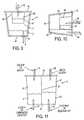
- FIG. 9shows an illustrative embodiment of a cartridge arranged to carbonate a liquid in the cartridge
- FIG. 10shows an illustrative embodiment of a cartridge arranged to carbonate a liquid in the cartridge in an alternative orientation
- FIG. 11shows an illustrative embodiment of a cartridge having isolated chambers containing a gas source and a beverage medium.
- a fluidsuch as water, water vapor, or other
- a fluidmay be provided to a carbon dioxide source in a cartridge so as to cause the carbon dioxide source to emit carbon dioxide gas that is used to carbonate a liquid.
- beverage forming machinemay include a carbon dioxide activating fluid supply arranged to provide fluid to a cartridge chamber for contact with the carbon dioxide source so as to cause the carbon dioxide source to emit carbon dioxide gas.
- a carbon dioxide gas supply of the machinemay be arranged to conduct carbon dioxide gas emitted by the carbon dioxide source, under pressure greater than the ambient pressure, to a precursor liquid to carbonate the precursor liquid.
- the carbon dioxide sourcemay be in solid form, such as a zeolite, activated carbon or other molecular sieve that is charged with carbon dioxide, and the use of a cartridge may not only isolate the carbon dioxide source from activating agents (such as water vapor in the case of a charged zeolite), but also potentially eliminate the need for a user to touch or otherwise directly handle the carbon dioxide source.
- a zeoliteactivated carbon or other molecular sieve that is charged with carbon dioxide
- Having a carbon dioxide activating fluid supplymay enable the use of another aspect of the invention, i.e., a volume or other measure of the fluid provided to the cartridge may be controlled to control the rate or amount of carbon dioxide that produced by the carbon dioxide source.
- This featurecan make the use of some carbon dioxide sources, such as a charged zeolite material, possible.
- zeolites charged with carbon dioxidetend to release carbon dioxide very rapidly and in relatively large quantities (e.g., a 30 gram mass of charged zeolite can easily produce 1-2 liters of carbon dioxide gas at atmospheric pressure in a few seconds in the presence of less than 30-50 ml of water).
- a carbonation “volume”refers to the number of volume measures of carbon dioxide gas that is dissolved in a given volume measure of liquid. For example, a 1 liter amount of “2 volume” carbonated water includes a 1 liter volume of water that has 2 liters of carbon dioxide gas dissolved in it. Similarly, a 1 liter amount of “4 volume” carbonated water includes a 1 liter volume of water that has 4 liters of carbon dioxide dissolved in it.
- the gas volume measureis the gas volume that could be released from the carbonated liquid at atmospheric or ambient pressure and room temperature. That is, dissolution of carbon dioxide or other gases in liquids typically takes a certain amount of time, and the rate of dissolution can only be increased a limited amount under less than extreme conditions, such as pressures within about 150 psi of ambient and temperatures within about +/ ⁇ 40 to 50 degrees C. of room temperature. By controlling the rate of carbon dioxide production for a carbon dioxide source, the total time over which the carbon dioxide source emits carbon dioxide can be extended, allowing time for the carbon dioxide to be dissolved without requiring relatively high pressures.
- This capabilityallows for a carbonated beverage machine to operate at relatively modest temperatures and pressures, potentially eliminating the need for relatively expensive high pressure tanks, conduits and other components, as well as extensive pressure releases, containment structures and other safety features that might otherwise be required, particularly for a machine to be used in the consumer's home.
- a portion of a precursor liquid that is used to form a beveragemay be used to activate the carbon dioxide source.
- This featuremay help simplify operation of a beverage making machine, e.g., by eliminating the need for special activation substances.
- a beverage making machine, or a method of forming a beveragemay be made less expensively and/or without special purpose ingredients.
- all that is needed to activate the carbon dioxide sourcemay be a portion of the water used to form the beverage.
- the cartridge that includes the carbon dioxide sourcemay include (as part of the source), an activating agent whose addition to another component of the carbon dioxide source is controlled to control carbon dioxide production.
- FIG. 1shows one illustrative embodiment that incorporates at least the aspects of providing a fluid to a cartridge and/or cartridge chamber to activate a carbon dioxide source, as well as controlling the fluid flow to control carbon dioxide production, and the use of a portion of beverage precursor liquid to activate a carbon dioxide source.
- the beverage making system 1 of FIG. 1includes a beverage precursor liquid 2 that is contained in a reservoir 11 .
- the beverage precursor liquid 2can be any suitable liquid, including water (e.g., flavored or otherwise treated water, such as sweetened, filtered, deionized, softened, carbonated, etc.), or any other suitable liquid used to form a beverage, such as milk, juice, coffee, tea, etc. (whether heated or cooled relative to room temperature or not).
- the reservoir 11is part of a beverage precursor supply 10 , which also includes a lid 12 that engages with the reservoir 11 to form a sealed enclosure, a pump 13 to circulate the precursor liquid 2 , and a nozzle, showerhead or other component 14 that serves to disperse the precursor liquid 2 in a headspace in the reservoir 11 .
- the precursor supply 10may be arranged in other ways, e.g., to include additional or different components.
- the reservoir 11 and lid 12may be replaced with a closed tank that has suitable inlet/outlet ports, the pump 13 and/or nozzle 14 may be eliminated, and or other changes.
- the reservoir 11is initially provided with the precursor liquid 2 by a user, who provides the liquid 2 in the reservoir 11 , e.g., from a water tap or other source.
- the usermay also provide ice or other cooling medium in the reservoir 11 as desired, so as to cool the ultimate beverage made.
- the system 1may include a refrigeration system or other cooling system (such as that found in refrigerators, air conditioning units, thermoelectric cooling units, or other devices used to remove heat from a material) to cool the liquid 2 .
- cooling the precursor liquid 2may help the carbonation process, e.g., because cooler liquids tend to dissolve carbon dioxide or other gas more rapidly and/or are capable of dissolving larger amounts of gas.
- a carbonated liquidmay be cooled after the carbonation process is complete, e.g., just before discharge using a flow through chiller.
- This featuremay allow the system 1 to chill only the beverage, and not other portions of the system, such as the reservoir 11 , carbonator, pump, etc., reducing the heat output by the system 1 .
- the precursor supply 10may include other components to provide liquid 2 to the reservoir 11 , such as a plumbed water line, controllable valve, and liquid level sensor to automatically fill the reservoir 11 to a desired level, a second water reservoir or other tank that is fluidly connected to the reservoir 11 (e.g., such as a removable water tank found with some coffee making machines along with a pump and conduit to route water from the removable tank to the reservoir 11 ), and other arrangements.
- a plumbed water line, controllable valve, and liquid level sensorto automatically fill the reservoir 11 to a desired level
- a second water reservoir or other tankthat is fluidly connected to the reservoir 11 (e.g., such as a removable water tank found with some coffee making machines along with a pump and conduit to route water from the removable tank to the reservoir 11 ), and other arrangements.
- the beverage making system 1also includes a carbon dioxide activating fluid supply 20 that provides a fluid to a cartridge 4 so as to activate a carbon dioxide source 41 to release carbon dioxide gas.
- the carbon dioxide source 41is located in a portion of the cartridge 4 and includes a charged adsorbent or molecular sieve, e.g., a zeolite material that has adsorbed some amount of carbon dioxide gas that is released in the presence of water, whether in vapor or liquid form.
- a charged adsorbent or molecular sievee.g., a zeolite material that has adsorbed some amount of carbon dioxide gas that is released in the presence of water, whether in vapor or liquid form.
- other carbon dioxide source materialsmay be used, such as charcoal or other molecular sieve materials, or source materials that generate carbon dioxide by chemical means, such as sodium bicarbonate and citric acid (with the addition of water if the bicarbonate and acid are initially in dry form), or others.
- the charged adsorbentis a zeolite such as analcime, chabazite, clinoptilolite, heulandite, natrolite, phillipsite, or stilbite.
- the zeolitemay be naturally occurring or synthetic, and may be capable of holding up to about 20% carbon dioxide by weight or more.
- the zeolite materialmay be arranged in any suitable form, such as a solid block (e.g., in disc form), particles of spherical, cubic, irregular or other suitable shape, and others.
- An arrangement that allows the zeolite to flow or be flowable, e.g., spherical particles,may be useful for packaging the zeolite in individual cartridges. Such an arrangement may allow the zeolite to flow from a hopper into a cartridge container, for example, simplifying the manufacturing process.
- the surface area of the zeolite particlesmay also be arranged to help control the rate at which the zeolite releases carbon dioxide gas, since higher surface area measures typically increase the gas production rate.
- zeolite materialswill release adsorbed carbon dioxide in the presence of water in liquid or vapor form, allowing the zeolite to be activated to release carbon dioxide gas by the addition of liquid water to the zeolite.
- the carbon dioxide activating fluid supply 20 in this embodimentincludes a conduit that is fluidly coupled to the pump 13 and a valve 21 that can be controlled to open/close or otherwise control the flow of precursor liquid 2 into the cartridge 4 .
- circulation of the liquid 2 by the pump 13can allow the activating fluid supply 20 to divert some (e.g., a first portion) of the precursor liquid 2 to the cartridge chamber 3 to cause the creation of carbon dioxide gas, e.g., by opening the valve 21 .
- the carbon dioxide activating fluid supply 20may include a syringe, piston pump or other positive displacement device that can meter desired amounts of liquid (whether water, citric acid or other material) that are delivered to the cartridge 4 .
- the activating fluid supply 20may include a gravity fed liquid supply that has a controllable delivery rate, e.g., like the drip-type liquid supply systems used with intravenous lines for providing liquids to hospital patients, or may spray atomized water or other liquid to provide a water vapor or other gas phase activating fluid to the cartridge 4 .
- FIG. 1suggests that the activating fluid supply 20 provides liquid to a top of the cartridge 4
- the liquid source 20may provide the fluid to a bottom of the cartridge 4 , e.g., to flood the bottom of the cartridge, or other suitable location.
- an activating liquidcan be provided in the cartridge with the carbon dioxide source 42 , e.g., in a chamber that is pierced to allow contact of the liquid with the source 42 .
- the cartridge 4(having one or more portions) may be located in a cartridge chamber 3 during carbon dioxide production.
- the cartridge 4may be made of a relatively flexible material or otherwise constructed so that the cartridge 4 cannot withstand a relatively high pressure gradient between the interior and exterior of the cartridge 4 . That is, the cartridge chamber 3 may contain any pressure generated by the carbon dioxide source 41 and support the cartridge 4 as necessary.
- the cartridge 4is contained in a closed and sealed chamber 3 that has a space or gap surrounding all or most of the cartridge 4 .
- the pressure between the interior space of the cartridge 4 and the exterior of the cartridge 4is allowed to equalize, e.g., by allowing some of the gas emitted by the carbon dioxide source 41 to “leak” into the space around the cartridge 4 , and so even if the cartridge 4 is made of a relatively semi-rigid, flexible or weak material, the cartridge 4 will not burst or collapse.
- the cartridge 4may be made to fit a receiving space in the cartridge chamber 3 so that the chamber 3 supports the cartridge 4 when pressure is built up inside the cartridge 4 . This support may be suitable to prevent the cartridge 4 from bursting or otherwise preventing the cartridge 4 from functioning as desired.
- the cartridge 4may be made suitably robust (either in whole or in part) so as to withstand relatively high pressures (e.g., 1 atm or more) in the cartridge interior space.
- relatively high pressurese.g. 1 atm or more
- the cartridge chamber 3need not function as much more than a physical support to hold the cartridge 4 in place or otherwise establish a connection to the cartridge for gas output by the cartridge 4 and/or liquid supply to the cartridge 4 .
- the cartridgemay be mechanically robust enough to withstand pressures up to 90 psig, e.g., like a conventional carbonated soft drink can.
- a carbon dioxide gas supply 30may be arranged to provide carbon dioxide gas from the cartridge chamber 3 to an area where the gas is used to carbonate the liquid 2 .
- the gas supply 30may be arranged in any suitable way, and in this illustrative embodiment includes a conduit 31 that is fluidly connected between the cartridge chamber 3 and the reservoir 11 , and a filter 32 that helps to remove materials that may contaminate the precursor liquid 2 , such as particles from the carbon dioxide source 41 .
- the gas supply 30may include other components, such as pressure regulators, safety valves, control valves, a compressor or pump (e.g., to increase a pressure of the gas), an accumulator (e.g., to help maintain a relatively constant gas pressure and/or store gas), and so on.
- the conduit 31extends below the surface of the precursor liquid 2 in the reservoir 11 so that the carbon dioxide gas is injected into the liquid 2 for dissolution.
- the conduit 31may include a sparging nozzle or other arrangement to aid in dissolution, e.g., by creating relatively small gas bubbles in the liquid 2 to increase the dissolution rate.
- the conduit 31may deliver the gas to a headspace (if present) in the reservoir 11 rather than below the surface of the liquid 2 .
- Carbonation of the precursor liquid 2may occur via one or more mechanisms or processes, and thus is not limited to one particular process.
- carbon dioxide gas delivered by the conduit 31 to the reservoir 11may function to help dissolve carbon dioxide in the liquid 2
- other system componentsmay further aid in the carbonation process.
- the precursor supply 10may assist in carbonating the liquid by circulating the liquid via the pump 13 and the nozzle 14 . That is, liquid 2 may be drawn from the reservoir 13 via a dip tube 15 and sprayed by the nozzle 14 into a carbon dioxide-filled headspace in the reservoir 11 .
- this processcan help the liquid 2 to dissolve carbon dioxide gas, e.g., by increasing the surface area of liquid 2 exposed to gas.
- the dip tube 15is separate from the reservoir 11 and extends below the surface of the precursor liquid 2
- the dip tube 15may be arranged in other ways, such as being made integrally with the wall of the reservoir 11 . If the dip tube 15 is made integrally with the reservoir 11 , connecting the reservoir 11 to the lid 12 may establish a fluid connection between the dip tube 15 and the pump 13 . Forming the dip tube 15 integrally with the reservoir 11 may allow the system 1 to accommodate differently sized (and thus different volume) reservoirs 11 . In addition, this arrangement may help ensure that only suitably configured reservoirs 11 (e.g., a container arranged to withstand system pressures) is used. Alternately, the dip tube 15 could be made flexible or otherwise accommodate reservoirs 11 having a different height.
- the dip tube 15may include a filter, strainer or other arrangement to help prevent small particles, such as ice chips, from being drawn into the pump 13 .
- the reservoirs 11can function as a drinking glass as well as a reservoir 11 in the system 1 . That is, a user may provide a reservoir/drinking glass 11 to the system 1 (e.g., including a desired amount of water, ice and/or beverage medium), and after carbonation is complete, use the reservoir/drinking glass 11 to enjoy the beverage.
- the reservoir 11may be insulated, e.g., to help keep a beverage cold, as well as made to withstand suitable pressures experienced in use with the system 1 .
- the various components of the system 1may be controlled by a controller 5 , which may include a programmed general purpose computer and/or other data processing device along with suitable software or other operating instructions, one or more memories (including non-transient storage media that may store software and/or other operating instructions), a power supply for the controller 5 and/or other system components, temperature and liquid level sensors, pressure sensors, RFID interrogation devices, input/output interfaces (e.g., to display information to a user and/or receive input from a user), communication buses or other links, a display, switches, relays, triacs, motors, mechanical linkages and/or actuators, or other components necessary to perform desired input/output or other functions.
- a controller 5may include a programmed general purpose computer and/or other data processing device along with suitable software or other operating instructions, one or more memories (including non-transient storage media that may store software and/or other operating instructions), a power supply for the controller 5 and/or other system components, temperature and liquid level sensors, pressure sensors, RFID interrogation
- the controller 5controls the operation of the valve 21 of the activating fluid supply 20 as well as the pump 13 of the precursor liquid supply 10 .
- a sensor 51which may represent one or more sensors used by the controller 5 .
- the sensor 51may include a temperature sensor that detects the temperature of the precursor liquid in the reservoir 11 . This information may be used to control system operation, e.g., warmer precursor liquid temperatures may cause the controller 5 to increase an amount of time allowed for carbon dioxide gas to be dissolved in the precursor liquid 2 .
- the temperature of the precursor liquid 2may be used to determine whether the system 1 will be operated to carbonate the liquid 2 or not.
- the usermay be required to add suitably cold liquid 2 (and/or ice) to the reservoir 11 before the system 1 will operate.
- the sensor 51may include a pressure sensor used to detect a pressure in the reservoir 11 . This information may be used to determine whether the reservoir 11 is improperly sealed to the lid 12 or another pressure leak is present, and/or to determine whether sufficient carbon dioxide gas is being produced by the cartridge 4 .
- low detected pressuremay cause the controller 5 to allow more liquid to be delivered by the activating fluid supply 20 to the cartridge 4 , or prompt the user to check that the reservoir 11 is properly engaged with the lid 12 .
- the controller 5can control the gas pressure in the reservoir 11 and/or other areas of the system 1 by controlling an amount of liquid delivered to the cartridge 4 and/or the cartridge chamber 3 .
- the sensor 51may alternately, or additionally, detect that the reservoir 11 is in place, and/or whether the reservoir 11 is properly engaged with the lid 12 .
- a switchmay be closed when the reservoir 11 is properly seated on a seal of the lid 12 , indicating proper engagement.
- the reservoir 11may include an RFID tag or other electronic device that is capable of communicating its identity or other characteristics of the reservoir 11 to the controller 5 .
- This informationmay be used to confirm whether the reservoir 11 is suitable for use with the system 1 , to control certain operating conditions (e.g., an operating pressure may be limited based on the type of reservoir used, the precursor liquid may be carbonated to a level that corresponds to the reservoir 11 , and so on), and/or for other uses.
- the sensor 51could also detect the presence of a cartridge 4 in the chamber 3 , e.g., via RFID tag, optical recognition, physical sensing, etc. If no cartridge 4 is detected, or the controller 5 detects that the cartridge 4 is spent, the controller 5 may prompt the user to insert a new or different cartridge 4 . For example, in some embodiments, a single cartridge 4 may be used to carbonate multiple volumes of precursor liquid 2 .
- the controller 5may keep track of the number of times that the cartridge 4 has been used, and once a limit has been reached (e.g., 10 drinks), prompt the user to replace the cartridge.
- Other parametersmay be detected by the sensor 51 , such as a carbonation level of the precursor liquid 2 , the presence of a suitable vessel to receive a beverage discharged from the system 1 (e.g., to prevent beverage from being spilled), the presence of water or other precursor liquid 2 in the reservoir 11 or elsewhere in the precursor supply 10 , a flow rate of liquid in the pump 13 or associated conduit, the presence of a headspace in the reservoir 11 (e.g., if no headspace is desired, a valve may be activated to discharge the headspace gas, or if only carbon dioxide is desired to be in the headspace, a sniffing valve may be activated to discharge air in the headspace and replace the air with carbon dioxide), and so on.
- a usermay first provide a desired amount of precursor liquid 2 in the reservoir 11 , along with optional ice and/or a beverage medium.
- the carbonated liquidmay be flavored after carbonation is complete either by automated or manual means.
- the reservoir 11is then engaged with the lid 12 , such as by engaging a screw thread on the reservoir 11 with the lid 12 , activating a clamp mechanism, or other.
- a cartridge 4 containing a carbon dioxide source 41e.g., in solid form, such as a charged zeolite
- the cartridge chamber 3may operate in any suitable way, e.g., like that found in many cartridge-based coffee or other beverage machines.
- a manual levermay be operated to lift a lid of the chamber 3 , exposing a cartridge receiver portion of the chamber 3 . With the cartridge 4 in the chamber 3 , the lever may be again activated to close the lid, sealing the chamber 3 closed.
- the controller 5may then activate the system 1 to deliver liquid to the chamber 3 , e.g., to cause carbon dioxide to be generated.
- the controller 5may start operation in an automated way, e.g., based on detecting the presence of a cartridge 4 in the chamber 3 , liquid 2 in the reservoir 11 and closure of the chamber 3 . Alternately, the controller 5 may start system operation in response to a user pressing a start button or otherwise providing input (e.g., by voice activation) to start beverage preparation.
- the controller 5may start operation of the pump 13 , drawing liquid from the dip tube 15 and discharging the liquid 2 at the nozzle 14 .
- the valve 21may be opened to deliver a suitable portion of the precursor liquid 2 to the chamber 3 , and carbon dioxide gas created may be provided to the reservoir 11 by the gas supply 30 . Operation may continue for a preset amount of time, or based on other conditions, such as a detected level of carbonation, a drop in gas production by the cartridge 4 , or other parameters.
- the amount of liquid provided to the chamber 3may be controlled to control gas output by the cartridge 4 .
- Control of the liquid provided to the cartridge 4may be made based on a timing sequence (e.g., the valve 21 may be opened for a period of time, followed by valve closure for a period, and so on), based on detected pressure (e.g., liquid supply may be stopped when the pressure in the chamber 3 and/or reservoir 11 exceeds a threshold, and resume when the pressure falls below the threshold or another value), based on a volume of activating liquid delivered to the chamber 3 (e.g., a specific volume of liquid may be delivered to the cartridge 4 ), or other arrangements.
- the usermay remove the beverage and reservoir 11 from the lid 12 .
- FIG. 1shows only one illustrative embodiment of a beverage making system 1 , but other arrangements are possible, including systems that incorporate other aspects of the invention.
- flavoring of a carbonated beveragemay be done in an automated way, and may occur in a cartridge.
- This featuremay make the beverage formation process easier and more convenient for a user, as well as help reduce the likelihood of cross contamination between beverages and/or the need to rinse a mixing chamber. That is, by mixing a beverage medium with the precursor liquid in a cartridge (which may be disposable), each beverage made by the system 1 may effectively be made using its own mixing chamber.
- precursor liquidmay be carbonated using a contactor (a type of carbonator) that includes a porous membrane (e.g., that is porous at least to gas) having a gas side and a liquid side.
- a contactora type of carbonator
- Precursor liquid on the liquid side of the carbonatormay be exposed to gas on the gas side of the membrane, and since the membrane may be arranged to increase the surface area of the liquid exposed to gas, dissolution of carbon dioxide or other gas into the precursor liquid may be done more rapidly than using other techniques.
- the carbonatormay include a contactor with a hollow fiber arrangement in which hollow fibers made of a hydrophobic material, such as polypropylene, carry the precursor liquid.
- the fibersare porous, having holes that, combined with the hydrophobicity of the material, allow for contact of gas on the exterior of the fibers with the liquid while preventing the liquid from exiting the fiber interior.
- Membrane contactors suitable for such useare made by Membrana of Charlotte, N.C., USA.
- a cartridge chamber of a beverage making systemmay be arranged to hold first and second cartridge portions where the first cartridge portion contains a carbon dioxide source arranged to emit carbon dioxide gas for use in carbonating the precursor liquid, and the second cartridge portion contains a beverage medium arranged to be mixed with a liquid precursor to form a beverage.
- the cartridge chambermay have a single cartridge receiving portion for receiving both cartridge portions, or may include a plurality of cartridge receiving portions that are separate from each other, e.g., for receiving two or more cartridges that are each associated with a first or second cartridge portion. Such an arrangement may help simplify use of the system, particularly where the cartridge portions are arranged for only a single use, e.g., formation of a single volume of beverage and discarded thereafter.
- a usermay be enabled to place one or two cartridges that include the first and second cartridge portions in receiving portions of the cartridge chamber without the need for establishing pressure-tight, leak-proof or other connections needed for the system to operate properly. Instead, the cartridge portions may be simply placed in a receiver, and the cartridge chamber closed, making the system ready for beverage production.
- FIG. 2shows another illustrative embodiment that incorporates the aspects of using a membrane contactor to carbonate the precursor liquid with a cartridge-provided gas, mixing a beverage medium with liquid in a cartridge, and the use of a cartridge chamber that receives first and second cartridge portions that respectively contain a gas source and beverage medium.
- This embodimentis similar to that in FIG. 1 in many ways, and may be modified to have one or more components like that in FIG. 1 .
- certain alternate arrangementsare shown in FIG. 2 to illustrate another few ways in which a beverage making system 1 may be modified in accordance with aspects of the invention.
- the reservoir 11is a closed tank having no removable lid.
- the reservoir 11may have any suitable volume, and is fluidly coupled to a pump 13 that can circulate the precursor liquid 2 through a contactor 6 and back to the reservoir 11 via a nozzle 14 .
- the precursor liquid 2may pass through hollow fibers in the contactor 6 to pick up carbon dioxide or other gas around the fibers, but this arrangement could be reversed, with gas flowing in the fibers and the precursor liquid 2 located on the exterior of the fibers.
- a filter 16may be provided to remove materials in the precursor liquid 2 that might clog the fibers, pores in the fibers or otherwise interfere with the operation of the contactor 6 .
- the filter 16may condition the liquid 2 , e.g., by softening, removing alkaline or other elements that tend to raise the pH of the liquid 2 , by removing elements that may prevent the formation of a good tasting beverage, and so on.
- the filter 16may include an activated charcoal and/or other components found in commonly used water filters.
- the contactor 6may be arranged to have a plurality of hollow fibers extending within a closed tube or other chamber so that the inner passages of the fibers fluidly connects a fluid inlet of the contactor 6 to a fluid outlet.
- the gas space around the fibersmay communicate with the carbon dioxide supply 30 via one or more ports on the gas side of the contactor 6 .
- the contactor 6may be arranged in other ways, such as having one or more membranes in the form of a flat sheet or other forms other than tubular to define a liquid side and a gas side of the contactor 6 .
- the activating fluid supply 20is arranged similarly to that in FIG. 1 , with a controllable valve 21 fluidly coupled to an output of the pump 13 .
- the activating fluid supply 20introduces liquid near a bottom of the cartridge chamber 3 and the cartridge 4 .
- This arrangementmay help the activating fluid supply 20 to better control gas release from the carbon dioxide source 41 .
- dropping water onto the carbon dioxide source 41 from the topmay allow the water to spread over a wide area, allowing charged zeolites or other source materials spread over a wide area to release gas.
- the activating fluid supply 20may flood the cartridge 4 and/or chamber 3 , thereby allowing water to contact source materials 41 starting from the bottom up.
- the carbon dioxide source 41can wick or otherwise move water upwardly (such as by capillary action), portions of the source 41 may be separated from each other by non-wicking agents.
- the source 41may include a set of stacked discs of zeolite material that are separated by a non-wicking material, such as metal or solid plastic separators. This may allow the fluid supply 20 to stepwise increase the fluid level in the cartridge 4 over a period of time to sequentially activate individual discs.
- Gas produced by the cartridge 4is routed by the gas supply 30 (via an optional filter 32 and conduit 31 ) to the gas side of the contactor 6 .
- the conduit 31may include a water-buoyant check valve or other arrangement that allows gas to pass to the contactor 6 , but prevents liquid from exiting the cartridge chamber 3 .
- a floating ball in the cartridge chamber 3may normally leave an opening of the conduit 31 free for gas flow, but may raise upwardly on the surface of liquid in the cartridge 4 to close the opening, e.g., in case that the activating fluid supply 20 provides an excess of activating liquid.
- the controller 5may monitor the gas pressure in the chamber 3 , in the conduit 31 and/or in the gas side of the contactor 6 to control the activating fluid supply 20 and gas production.
- the activating fluid supply 20may be controlled to provide approximately 35-45 psi gas pressure at the gas side of the contactor 6 .
- This pressurehas been found to work at least adequately in carbonating about 400-500 ml of water at a temperature of about 0 degrees C. in about 30-60 seconds using a hollow fiber contactor, as described in more detail below in the Examples.
- carbon dioxide in the contactoris dissolved into the precursor liquid 2 , the pressure on the gas side will drop, prompting the controller 5 to supply additional liquid 2 to the cartridge 4 a to cause additional gas to be created. Similar to the system in FIG.
- this processmay be performed based on any criteria, such as the passage of a specific amount of time, the detection of a specified level of carbonation of the liquid 2 , exhaustion of the carbon dioxide source 41 , a volume of liquid delivered to the cartridge 4 a , etc., so that a pressure of the carbon dioxide gas can be maintained within a desired range above ambient pressure.
- the controller 5may direct the liquid 2 to a beverage medium cartridge 4 b in the cartridge chamber 3 . While the precursor liquid 2 may be caused to flow from the reservoir 11 in any suitable way (such as by gravity, a pump, etc.), in this embodiment, the controller 5 activates an air pump 7 which pressurizes the reservoir 11 such that the precursor liquid 2 is forced to flow via a conduit to the cartridge chamber 3 and the beverage medium cartridge 4 b . In other embodiments, gas pressure created by the carbon dioxide source 41 may be used to pressurize the reservoir 11 and drive the flow of the precursor liquid to the beverage medium cartridge 4 b .
- gas from the cartridge 4 amay be routed directly into the reservoir 11 instead of to the contactor 6 so as to pressurize the reservoir 11 .
- a controllable valve, pump or other suitable componentmay be added to control flow as desired.
- the use of air or other gas to move liquid 2 through the cartridge 4 b (or to expel beverage medium from the cartridge 4 b )may allow the system 1 to “blow down” the cartridge 4 b at or near the end of the beverage process, e.g., to remove any remaining material from the cartridge 4 b .
- a similar processmay be used to blow down the cartridge 4 a , e.g., using an air pump or gas produced by the source 41 .
- the beverage medium cartridge 4 bmay include any suitable beverage making materials (beverage medium), such as concentrated syrups, ground coffee or liquid coffee extract, tea leaves, dry herbal tea, powdered beverage concentrate, dried fruit extract or powder, natural and/or artificial flavors or colors, acids, aromas, viscosity modifiers, clouding agents, antioxidants, powdered or liquid concentrated bouillon or other soup, powdered or liquid medicinal materials (such as powdered vitamins, minerals, bioactive ingredients, drugs or other pharmaceuticals, nutriceuticals, etc.), powdered or liquid milk or other creamers, sweeteners, thickeners, and so on.
- beverage making materialssuch as concentrated syrups, ground coffee or liquid coffee extract, tea leaves, dry herbal tea, powdered beverage concentrate, dried fruit extract or powder, natural and/or artificial flavors or colors, acids, aromas, viscosity modifiers, clouding agents, antioxidants, powdered or liquid concentrated bouillon or other soup, powdered or liquid medicinal materials (such as powdered vitamins, minerals, bioactive ingredients, drugs or other pharmaceutical
- mixingof a liquid with a beverage medium includes a variety of mechanisms, such as the dissolving of substances in the beverage medium in the liquid, the extraction of substances from the beverage medium, and/or the liquid otherwise receiving some material from the beverage medium.
- the liquid 2may be introduced into the cartridge 4 b in any suitable way, and/or the cartridge 4 b may be arranged in any suitable way to aid in mixing of the liquid 2 with the beverage medium 42 .
- the precursor liquid 2may be introduced into the cartridge 4 b so as to cause a spiral or other flow pattern
- the cartridge 4 bmay include a labyrinth or other tortuous flow path to cause turbulence in the flow to aid in mixing, and so on.
- One potential advantage of mixing the precursor liquid 2 in a beverage medium cartridge 4 bis that cross contamination of beverage medium that may occur with the use of a mixing chamber that is used to mix beverage medium and liquid 2 for every beverage made by the system 1 may be avoided.
- the system 1could be modified to employ a reused mixing chamber, e.g., a space where beverage medium 42 that is provided from a cartridge 4 b and precursor liquid 2 are mixed together in much the same way that fountain drinks are formed by commercial drink machines.
- the beverage medium 42could be driven from the cartridge 4 b (e.g., by air pressure, carbon dioxide gas pressure created by the cartridge 4 a , by gravity, by suction created by an adductor pump, venturi or other arrangement, etc.) into a mixing chamber where the precursor liquid 2 is also introduced. Rinsing of the mixing chamber may or may not be necessary, e.g., to help prevent cross contamination between beverages. In some arrangements, the entire volume of beverage medium 42 may be discharged into the mixing chamber, causing initial amounts of flavored precursor liquid 2 exiting the mixing chamber to have a high beverage medium concentration. However, as the beverage medium 42 is swept from the mixing chamber by the precursor liquid 2 , the precursor liquid itself may effectively rinse the mixing chamber.
- FIG. 2could be modified so that flow of precursor liquid 2 exiting the contactor 6 is routed directly to the beverage medium cartridge 4 b or to another mixing chamber where beverage medium 42 is mixed with the carbonated precursor liquid 2 , e.g., like that shown in FIG. 3 . That is, in this illustrative embodiment, carbonated precursor liquid 2 does not circulate from the reservoir 11 , through the contactor 6 and back to the reservoir 11 , but instead precursor liquid 2 makes a single pass through the contactor 6 and then proceeds to mixing with the beverage medium 42 in a mixing chamber 9 and discharge to a cup 8 .
- the mixing chamber 9may take any suitable form, e.g., may cause the precursor liquid 2 and beverage medium 42 to move in a spiral, swirl or other fashion to enhance mixing, may have one or more motor driven blades, impellers or other elements to mix contents in the chamber 9 , and so on.
- the mixing chamber 9may be cooled as well, e.g., by a refrigeration system, to help cool the beverage provided to the cup 8 .
- the precursor liquid 2may be cooled in the reservoir 11 and/or any other locations in the system 1 .
- the mixing chamber 9may be eliminated or arranged to mix the precursor liquid 2 and beverage medium 42 upstream of the contactor 6 .
- the precursor liquid supply 10may be arranged to mix the precursor liquid 2 with the beverage medium 42 in the cartridge 4 b prior to routing the liquid 2 to the contactor 6 .
- the controller 5may detect the gas pressure on the gas side of the contactor 6 , and control fluid supply to the cartridge 4 a accordingly, e.g., to maintain a suitable gas pressure in the contactor 6 .
- the reservoir 11may be a water storage tank that is not pressurized in this embodiment, and may be removable from the system 1 , e.g., to make filling by a user easier.
- the usermay add ice and/or beverage medium to the precursor liquid 2 in the reservoir 11 , if desired.
- the reservoir 11 and pump 13may be replaced by a plumbed connection to a pressurized water supply and an optional control valve and/or pressure reducer.
- the system 1may be suitably enclosed in a housing having a visible display, user input buttons, knobs, or touch screen, user-operated devices for opening/closing a cartridge chamber, and other features found in beverage making machines.
- the cartridge chamber 3is combined with the reservoir 11 such that the cartridge 4 a having a carbon dioxide source 41 is located in the reservoir 11 .
- the cartridge 4 amay be placed in the reservoir 11 /cartridge chamber 3 by removing the lid 12 from the reservoir 11 .
- Liquidmay be provided to the cartridge 4 a by any suitable activating fluid supply 20 , such as an arrangement like that in FIG. 1 , a syringe or piston pump that delivers a metered amount of liquid to the cartridge 4 a , and others.
- the carbon dioxide supply 30is combined with the reservoir 11 such that a portion of the reservoir functions to deliver carbon dioxide gas to the precursor liquid 2 .
- the pump 13may aid the carbonation process by circulating the liquid 2 and spraying the liquid 2 into a carbon dioxide-filled headspace in the reservoir 11 .
- a contactor 6may be provided in the reservoir 11 (e.g., at the location of the nozzle 14 ) so that the liquid 2 flows through hollow fibers extending downwardly from the lid 12 while carbon dioxide in the headspace is absorbed by the liquid while passing through the fibers.
- the membrane portion of a contactor 6may be at least partially submerged in the precursor liquid 2 , and gas from the source 41 may be passed through hollow fibers of the contactor 6 . As a result, the liquid 2 on the outside of the fibers may pick up carbon dioxide from the gas passing through the fibers.
- FIG. 5shows one illustrative arrangement in which both a carbon dioxide source cartridge 4 a and a beverage medium cartridge 4 b can be received by the same cartridge chamber 3 .
- the cartridges 4 a , 4 b(which respectively have a portion that contains a gas source 41 and beverage medium 42 ) are received in separate cartridge receivers 33 , and each cartridge receiver 33 may include a piercing element 34 at a bottom of the cartridge receiver 33 .
- the piercing element 34which may include a hollow needle, spike, blade, knife or other arrangement, may form an opening in the respective cartridge 4 .
- the cartridges 4may have defined openings, e.g., one or more ports, that include a septum or other valve-type element that permits flow into and/or out of the cartridge 4 .
- the lid 12may include piercing element 35 that form an opening in the top of the respective cartridge 4 , e.g., when the lid 12 is closed. When closed, the lid 12 may form a sealed chamber in which the cartridges 4 a , 4 b are located and isolated from each other.
- the openings formed in the cartridges 4 a , 4 bmay allow for communication with the interior space of the cartridges 4 a , 4 b as outlined in FIG. 5 .
- an opening at the top of the cartridge 4 amay allow carbon dioxide or other gas to exit the cartridge chamber 3
- the opening at the bottom of the cartridge 4 amay allow for water or other activating fluid to enter the cartridge 4 a
- the openingsmay be formed in other locations, such as an opening for allowing fluid input to occur at the top or side of the cartridge.
- gasmay exit the cartridge through a bottom, side or otherwise located opening.
- gasmay be permitted to leak from the cartridge 4 a into the space in the cartridge chamber 3 around the cartridge 4 a , e.g., through the opening in the cartridge 4 a , through a hole or other opening in the piercing element 35 , etc.
- the cartridge 4 amay fit closely into the cartridge receiver 33 so that the cartridge chamber 3 can support the cartridge 4 a (if necessary).
- the opening in the top of the beverage medium cartridge 4 bmay allow for precursor liquid 2 to be introduced into the cartridge 4 b (e.g., for mixing with the beverage medium), or for pressurized air or other gas to enter the cartridge (e.g., for forcing the beverage medium 42 from the cartridge 4 b and into a mixing chamber).
- the opening at the bottom of the cartridge 4 bmay allow for beverage to exit to a waiting cup or other container, or for the beverage medium to travel to a mixing chamber.
- opening in the beverage medium cartridge 42may be arranged in any suitable location or locations.
- the cartridge chamber 3may open and close in any suitable way to allow cartridges 4 to be placed in and/or removed from the chamber 3 .
- the lid 12is pivotally mounted to the receiver portion of the chamber 3 , and may be opened and closed manually, such as by a handle and linkage arrangement, or automatically, such as by a motor drive, to close the cartridge receivers 33 .
- the lid 12may have two or more sections that are each associated with a respective cartridge receiver 33 . Thus, the lid sections can be moved independently of each other to open/close the cartridge receivers 33 .
- a cartridge chamber 3need not necessarily have a lid and receiver arrangement like that shown in FIG. 5 , but instead may have any suitable member or members that cooperate to open/close and support a cartridge.
- a pair of clamshell membersmay be movable relative to each other to allow receipt of a cartridge and physical support of the cartridge.
- the cartridge chamber 3may allow a user to place one or more cartridges in the chamber 3 without the need for the user to take special steps to establish a pressure-tight, leak-proof or other specialized connection between the cartridge and other portions of the system 1 . Instead, in some embodiments, the user may be able to simply place the cartridge in a receiving space, and close the cartridge chamber.
- the cartridges 4 used in various embodimentsmay be arranged in any suitable way, such as a relatively simple frustoconical cup-shaped container having a lid attached to the top of the container, e.g., like that in some beverage cartridges sold by Keurig, Incorporated of Reading, Mass. and shown in U.S. Pat. No. 5,840,189, for example.
- a cartridge having a frustoconical cup-shaped container and lidmay have an approximate diameter of about 30-50 mm, a height of about 30-50 mm, an internal volume of about 30-60 ml, and a burst resistance of about 80 psi (i.e., a resistance to cartridge bursting in the presence of a pressure gradient of about 80 psi from the inside to outside of the cartridge in the absence of any physical support for the cartridge).
- a “cartridge”may take any suitable form, such as a pod (e.g., opposed layers of filter paper encapsulating a material), capsule, sachet, package, or any other arrangement.
- the cartridgemay have a defined shape, or may have no defined shape (as is the case with some sachets or other packages made entirely of flexible material.
- the cartridgemay be impervious to air and/or liquid, or may allow water and/or air to pass into the cartridge.
- the cartridgemay include a filter or other arrangement, e.g., in the beverage medium cartridge 4 b to help prevent some portions of the beverage medium from being provided with the formed beverage, and/or in the gas cartridge 4 a to help prevent carbon dioxide source material from being introduced into the beverage or other system components.
- the cartridge or cartridges used to form a beverage using the beverage making systemmay have a volume that is less, and in some cases substantially less, than a beverage to be made using the cartridge(s).
- the cartridgesmay each have a volume that is about 50 ml or less, and be used to form a beverage having a volume of about 200-500 ml or more.
- an amount of charged carbon dioxide adsorbente.g., a charged zeolite
- an amount of charged carbon dioxide adsorbente.g., a charged zeolite
- beverage-making syrupshaving a volume of less than 50 ml can be used to make a suitably flavored beverage having a volume of about 400-500 ml.
- relatively small volume cartridgeshaving a volume of about 100 ml or less may be used to form a carbonated beverage having a volume of about 100 to 1000 ml, and a carbonation level of about 1.5 to 4 volumes in less than 120 seconds, e.g., about 60 seconds, and using pressures under 50 psi.
- the cartridges 4may be joined together, like that shown in FIG. 6 .
- the cartridges 4 a , 4 bmay be connected together by any suitable arrangement, such as tabs 43 that extend from respective cartridges 4 a , 4 b and are attached together, e.g., by thermal welding, adhesive, interlocking mechanical fasteners such as snaps or clips, etc.
- This arrangementmay allow the cartridges 4 a , 4 b to be made separately in the manufacturing setting, e.g., because the cartridges require very different processes for manufacturing.
- the beverage medium cartridge 4 bmay require a highly sterile environment, whereas the gas cartridges 4 a need not be made in such an environment.
- the gas cartridges 4 amay need to be manufactured in a water vapor-free environment, whereas the beverage medium cartridge 4 b may not be subject to such requirements.
- the cartridgesmay be attached together in a way that prevents their separation without the use of tools (such as a scissor) and/or damage to one or both of the cartridges.
- the cartridge chamber 3may be arranged to accommodate the attached cartridges, allowing a user to place a single item in the chamber 3 to form a beverage.
- the cartridges 4 and/or the way in which the cartridges are attached, together with the arrangement of the cartridge chamber 3may help ensure that the gas cartridge 4 a and beverage medium cartridge 4 b are placed in the proper cartridge receiver 33 .
- the cartridges 4may have different sizes, shapes or other configurations so that the combined cartridges 4 cannot be placed into the chamber 3 in the wrong orientation.
- the controller 5may detect that the cartridges have been improperly placed (e.g., by communicating with an RFID tag on one or both of the cartridges, by optically or otherwise identifying the cartridges, etc.), and prompt the user to make a change as necessary.
- FIGS. 7 and 8show another embodiment in which a pair of cartridges are joined together in a way that helps prevent improper placement of the cartridges in a chamber and/or enables the cartridges to operate in other orientations.
- the cartridges 4 a and 4 bare attached by a connection 43 such that with the cartridge 4 a arranged in an upright orientation with the container bottom 44 facing downward and the lid 45 covering the top of the container facing upward, the cartridge 4 b is on its side with the lid 45 facing to the side.
- FIG. 8shows a top view of the embodiment, with the lid 45 of the cartridge 4 a facing the viewer and the lid 45 of the cartridge 4 b facing downwardly.
- This arrangementmay be useful in embodiments where the cartridges 4 are pierced only at the lid area, e.g., are not pierced in the bottom 44 or other portions of the container. That is, the gas cartridge 4 a may be pierced at the lid 45 to allow liquid to be introduced into the cartridge 4 a , and to allow gas to exit. Similarly, the lid 45 of the cartridge 4 b may be pierced to allow liquid to be introduced into the cartridge 4 b for mixing with the beverage medium 42 and to allow a flavored beverage to exit the cartridge 4 b . Avoiding piercing of the container may be useful in arrangements where the container is made of a relatively thick and/or rigid material (e.g., to withstand operating pressures for the cartridge 4 ).
- a single cartridgemay be used to provide a carbonating gas as well as a beverage medium.
- the precursor liquidcan be both carbonated and flavored in the same cartridge.
- FIG. 9shows a cross sectional view of a cartridge 4 that includes both a gas source 41 (e.g., a zeolite carbon dioxide source) and a beverage medium 42 .
- the cartridge 4includes first and second chambers (or portions) 46 , 47 that respectively contain the gas source 41 and the beverage medium 42 .
- the first and second chambers (or portions) 46 , 47may be separated from each other by a permeable element, such as a filter, or an impermeable element, such as a wall molded with the cartridge container.
- first and second chambers (or portions) 46 , 47are separated by a filter 48 that is attached to the lid 45 , but could be arranged in other ways.
- Precursor liquid and/or an activating liquidmay be introduced into the first chamber 46 by a piercing element 35 or other arrangement, such as a port formed as part of the cartridge 4 .
- the interior space of the cartridge 4may be maintained under pressure, e.g., 30-150 psi above ambient or greater, so that dissolution of carbon dioxide gas released by the source 41 occurs more rapidly than would occur at lower pressures.
- the system 1 arranged to use such cartridgesmay include a backpressure valve or other arrangement that helps to maintain a suitable pressure in the cartridge 4 , e.g., as an aid to carbonation.
- a cartridge chamber 3 that holds the cartridge 4may be arranged to closely fit the cartridge 4 as needed to support the cartridge and prevent the cartridge from bursting.
- pressure in the cartridge 4may be allowed to leak into a space around the cartridge 4 to equalize the pressures inside and outside of the cartridge.
- Carbonated precursor liquid 2 and/or a liquid/gas bubble mixturemay pass through the filter 48 into the second chamber 47 for mixing with the beverage medium 42 .
- the precursor liquid 2 and beverage medium 42 mixturemay exit the cartridge 4 , e.g., through a piercing element 34 at the container bottom 44 .
- Dissolution of carbon dioxide into the precursor liquid 2may continue after the materials exit the cartridge 4 .
- a mixing chambermay be located downstream of the cartridge 4 to help more thoroughly mix the beverage medium and liquid if needed.
- a conduit downstream of the cartridgemay help continue dissolution of gas, e.g., by maintaining pressure in the liquid.
- FIG. 10shows an embodiment in which a cartridge configured like that in FIG. 9 is used while the cartridge 4 is on its side.
- Precursor liquidmay be introduced into the first chamber (or portion) 46 (e.g., via the piercing element 35 ), causing the gas source 41 to emit gas and at least partially flooding the cartridge 4 interior space.
- the liquidmay be carbonated and mix with the beverage medium 42 before exiting the cartridge, e.g., via the piercing element 34 .
- a single cartridge 4may be arranged to have first and second chambers 46 , 47 that are isolated from each other.
- FIG. 11shows one such embodiment in which first and second chambers (or portions) 46 , 47 are separated by a wall 49 .
- a cartridge like that shown in FIG. 11may be used, for example, in a system 1 like that shown in FIG. 2 , although the cartridge chamber 3 may need to be modified to accommodate the single cartridge 4 .
- activating liquidmay be provided via a piercing element 35 at a top of the first chamber (or portion) 46 , and gas may exit via the same or a different opening.
- activating liquidmay be introduced via the piercing element 34 at the bottom of the first chamber (or portion) 46 , and gas may exit via the piercing element 35 at the top.
- precursor liquidmay be introduced at the top piercing element 35 and carbonated liquid may exit via the bottom piercing element 34 .
- the first chamber (or portion) 46may include a filter or other suitable components, e.g., to help prevent the gas source 41 from exiting the chamber (or portion) 46 .
- air or other gasmay be introduced via the piercing element 35 at a top of the second chamber (or portion) 47 , causing beverage medium 42 to be moved out of the piercing element 34 at the bottom of the second chamber (or portion) 47 .
- precursor liquidmay be introduced via the piercing element 35 at a top of the second chamber 47 , may mix with the beverage medium 42 and exit the cartridge 4 out of the piercing element 34 .
- the piercing element 34 , 35 arrangement in this illustrative embodimentshould not be interpreted as limiting aspects of the invention in any way.
- piercing elementsneed not be used, but instead flow into/out of the cartridge 4 may occur through defined ports or other openings in the cartridge 4 .
- flow ports or other openings in the cartridgeneed not necessarily be located at the top, bottom or other specific location.
- the cartridge(s)may be made of any suitable materials, and are not limited to the container and lid constructions shown herein.
- the cartridge(s)may be made of, or otherwise include, materials that provide a barrier to moisture and/or gases, such as oxygen, water vapor, etc.
- the cartridge(s)may be made of a polymer laminate, e.g., formed from a sheet including a layer of polystyrene or polypropylene and a layer of EVOH and/or other barrier material, such as a metallic foil.
- the cartridge(s) materials and/or constructionmay vary according to the materials contained in the cartridge.
- a gas cartridge 4 amay require a robust moisture barrier, whereas a beverage medium cartridge 4 b may not require such a high moisture resistance.
- the cartridgesmay be made of different materials and/or in different ways.
- the cartridge interiormay be differently constructed according to a desired function.
- a beverage medium cartridge 4 bmay include baffles or other structures that cause the liquid/beverage medium to follow a tortuous path so as to encourage mixing.
- the gas cartridge 4 amay be arranged to hold the gas source 41 in a particular location or other arrangement in the interior space, e.g., to help control wetting of the source 41 with activating liquid.
- the release properties of a carbon dioxide adsorbentwere measured in the following way: 8 ⁇ 12 beads of sodium zeolite 13X (such as are commercially available from UOP MOLSIV Adsorbents) were obtained. The beads were placed in a ceramic dish and fired in a Vulcan D550 furnace manufactured by Ceramco. The temperature in the furnace containing the beads was raised to 550° C. at a rate of 3° C./min and was held at 550° C. for 5 hours for firing and preparation of the beads for charging with carbon dioxide.
- the beadswere removed from the furnace and immediately transferred to a metal container equipped with a tightly fitted lid and entrance and exit ports permitting circulation of gas. With the beads sealed in the container, the container was flooded with carbon dioxide gas and pressurized to 15 psig. (Note, however, that experiments have been performed between 5-32 psig.) The chamber was held at the set pressure for 1 hour. During this hold period the chamber was bled every 15 min. At the end of this period a quantity of gas had adsorbed to the beads.
- a 30 g sample of charged 13X zeolitewas measured, and a beaker filled with 250 ml of water at room temperature of 22° C. The beaker and water was placed on a balance and the balance zeroed. The 30 g of charged zeolite was then added to the beaker and the change in weight versus time was measured. It was shown that the change in weight became approximately steady after a period of 50 seconds, and that the beads lost about 4.2 g (14 wt %) of weight attributed to the release of carbon dioxide. Of course, some carbon dioxide may have been dissolved into the water.
- Charged zeolite 13Xwas prepared as in Example 1. A 30 g sample of the charged zeolites was then placed in metal chamber with a water inlet port at the bottom and a gas outlet port at the top. The chamber that held the zeolites was 34 ⁇ 34 mm in cross section and had 2 metal filter discs with 64 1/16′′ diameter holes to retain the zeolite material. Tap water was then flooded into the bottom of the chamber perpendicular to the cross-section at an average flow rate of 60 ml/min. Gas evolved through the top outlet port.
- the pressure of the gas in the chamberwas measured with a pressure gauge and controlled using a needle valve attached to the exit port of the gas chamber.
- the needle valvewas set to maintain the chamber at a pressure of 35 psig by manually adjusting the valve over the course of exposing charged zeolites in the chamber to water. Once the valve was set to an operating pressure, the system would perform repeatably with zeolite samples charged in the same manner.
- Charged zeolite 13Xwas prepared as in Example 1. A 30 g sample of the charged zeolites was then placed in a semi rigid 50 ml polystyrene-polyethylene-EVOH laminate cup container and thermally sealed with a foil lid. The sealed zeolite cartridges were then placed into a sealed, metal cartridge chamber and pierced on the top and bottom.
- Tap waterwas introduced at the bottom of the cartridge with the flow controlled by a solenoid valve.
- the solenoid valvewas actuated via a pressure switch connected to the top gas outlet of the cartridge chamber.
- the pressure switchwas set to three different operating pressures of 5, 22, and 35 psig.
- the resulting gas at the set pressureswas then introduced into the shellside of a hydrophobic membrane contactor (1 ⁇ 5.5 Minimodule from Liquicel, of Charlotte, N.C.).
- the other shellside portwas plugged to prevent gas from escaping.
- Water from a reservoir containing 400 ml of water and approximately 50 g of icewas circulated from the reservoir, through the contactor, and back to the reservoir (e.g., like that shown in FIG.
- the gaswas shown to evolve from the zeolites in the cartridges at a controllable rate (based on water delivery to the cartridge chamber) and then dissolved into water to produce a carbonated beverage.
- thisillustrates the concept that by controlling system pressures one can control the level of carbonation of the finished beverage. It is expected that higher system pressures, e.g., of about 40-50 psi above ambient, would produce a 4 volume carbonated beverage (having a liquid volume of about 500 ml) in about 60 seconds or less.
Landscapes
- Engineering & Computer Science (AREA)
- Chemical & Material Sciences (AREA)
- Food Science & Technology (AREA)
- Chemical Kinetics & Catalysis (AREA)
- Mechanical Engineering (AREA)
- Polymers & Plastics (AREA)
- Life Sciences & Earth Sciences (AREA)
- Nutrition Science (AREA)
- Health & Medical Sciences (AREA)
- Non-Alcoholic Beverages (AREA)
- Devices For Dispensing Beverages (AREA)
- Accessories For Mixers (AREA)
- Apparatus For Making Beverages (AREA)
Abstract
Description
| Time (sec) | Weight (grams) | |
| 0 | 30 | |
| 25 | 26.7 | |
| 50 | 25.8 | |
| 75 | 25.6 | |
| 100 | 25.5 | |
| Average Carbonation Level | ||
| System Pressure (psig) | (Volumes CO2dissolved) | |
| 10 | 1.35 | |
| 22 | 2.53 | |
| 35 | 3.46 | |
Claims (18)
Priority Applications (9)
| Application Number | Priority Date | Filing Date | Title |
|---|---|---|---|
| US13/017,459US8808775B2 (en) | 2010-02-01 | 2011-01-31 | Method and apparatus for cartridge-based carbonation of beverages |
| US13/565,214US9936834B2 (en) | 2010-02-01 | 2012-08-02 | Method and apparatus for cartridge-based carbonation of beverages |
| US14/332,816US10343885B2 (en) | 2010-02-01 | 2014-07-16 | Method and apparatus for cartridge-based carbonation of beverages |
| US14/332,856US9790076B2 (en) | 2010-02-01 | 2014-07-16 | Method and apparatus for cartridge-based carbonation of beverages |
| US14/445,521US20140335239A1 (en) | 2010-02-01 | 2014-07-29 | Method and apparatus for cartridge-based carbonation of beverages |
| US14/445,484US20140331867A1 (en) | 2010-02-01 | 2014-07-29 | Method and apparatus for cartridge-based carbonation of beverages |
| US14/445,571US9867493B2 (en) | 2010-02-01 | 2014-07-29 | Method and apparatus for cartridge-based carbonation of beverages |
| US15/872,833US10842313B2 (en) | 2010-02-01 | 2018-01-16 | Method and apparatus for cartridge-based carbonation of beverages |
| US15/948,871US20180289205A1 (en) | 2010-02-01 | 2018-04-09 | Method and apparatus for cartridge-based carbonation of beverages |
Applications Claiming Priority (2)
| Application Number | Priority Date | Filing Date | Title |
|---|---|---|---|
| US33718410P | 2010-02-01 | 2010-02-01 | |
| US13/017,459US8808775B2 (en) | 2010-02-01 | 2011-01-31 | Method and apparatus for cartridge-based carbonation of beverages |
Related Child Applications (4)
| Application Number | Title | Priority Date | Filing Date |
|---|---|---|---|
| US13/565,214Continuation-In-PartUS9936834B2 (en) | 2010-02-01 | 2012-08-02 | Method and apparatus for cartridge-based carbonation of beverages |
| US14/332,816DivisionUS10343885B2 (en) | 2010-02-01 | 2014-07-16 | Method and apparatus for cartridge-based carbonation of beverages |
| US14/332,856DivisionUS9790076B2 (en) | 2010-02-01 | 2014-07-16 | Method and apparatus for cartridge-based carbonation of beverages |
| US14/445,571Continuation-In-PartUS9867493B2 (en) | 2010-02-01 | 2014-07-29 | Method and apparatus for cartridge-based carbonation of beverages |
Publications (2)
| Publication Number | Publication Date |
|---|---|
| US20110226343A1 US20110226343A1 (en) | 2011-09-22 |
| US8808775B2true US8808775B2 (en) | 2014-08-19 |
Family
ID=43902978
Family Applications (3)
| Application Number | Title | Priority Date | Filing Date |
|---|---|---|---|
| US13/017,459Expired - Fee RelatedUS8808775B2 (en) | 2010-02-01 | 2011-01-31 | Method and apparatus for cartridge-based carbonation of beverages |
| US14/332,856Expired - Fee RelatedUS9790076B2 (en) | 2010-02-01 | 2014-07-16 | Method and apparatus for cartridge-based carbonation of beverages |
| US14/332,816ActiveUS10343885B2 (en) | 2010-02-01 | 2014-07-16 | Method and apparatus for cartridge-based carbonation of beverages |
Family Applications After (2)
| Application Number | Title | Priority Date | Filing Date |
|---|---|---|---|
| US14/332,856Expired - Fee RelatedUS9790076B2 (en) | 2010-02-01 | 2014-07-16 | Method and apparatus for cartridge-based carbonation of beverages |
| US14/332,816ActiveUS10343885B2 (en) | 2010-02-01 | 2014-07-16 | Method and apparatus for cartridge-based carbonation of beverages |
Country Status (16)
| Country | Link |
|---|---|
| US (3) | US8808775B2 (en) |
| EP (4) | EP2921087B1 (en) |
| JP (4) | JP5766212B2 (en) |
| KR (1) | KR20120134118A (en) |
| CN (4) | CN102843938B (en) |
| AU (1) | AU2011210627B2 (en) |
| BR (1) | BR112012019152A2 (en) |
| CA (2) | CA3024818A1 (en) |
| DK (4) | DK2921087T3 (en) |
| ES (4) | ES2532901T3 (en) |
| HK (2) | HK1216288A1 (en) |
| MX (1) | MX2012008857A (en) |
| MY (1) | MY163441A (en) |
| NZ (2) | NZ620266A (en) |
| TW (1) | TWI583311B (en) |
| WO (1) | WO2011094677A2 (en) |
Cited By (36)
| Publication number | Priority date | Publication date | Assignee | Title |
|---|---|---|---|---|
| US9346611B1 (en) | 2015-03-20 | 2016-05-24 | Meltz, LLC | Apparatus and processes for creating a consumable liquid food or beverage product from frozen contents |
| US9487348B2 (en) | 2015-03-20 | 2016-11-08 | Meltz, LLC | Systems for and methods of providing support for displaceable frozen contents in beverage and food receptacles |
| US9675203B2 (en) | 2015-03-20 | 2017-06-13 | Meltz, LLC | Methods of controlled heating and agitation for liquid food or beverage product creation |
| US9695030B2 (en) | 2014-07-22 | 2017-07-04 | BIBO Barmaid LLC | Cold beverage dispenser |
| US20170238756A1 (en)* | 2014-09-29 | 2017-08-24 | Luigi Lavazza S.P.A. | Dispensing assembly for machines for the preparation of liquid food products |
| US20170355585A1 (en)* | 2014-11-17 | 2017-12-14 | Apiqe Holdings, Llc | System, disposable cartridge, and method for the preparation of a liquid product |
| US9883766B2 (en)* | 2015-11-20 | 2018-02-06 | Pepsico, Inc. | Beverage dispenser systems and methods |
| US20180042273A1 (en)* | 2011-10-04 | 2018-02-15 | Duk Jong Jun | Method for dissolving carbon dioxide without pressurizing and cooling |
| US9932218B2 (en) | 2016-03-04 | 2018-04-03 | BIBO Barmaid LLC | Cold beverage dispenser and cutter assembly for cold beverage dispenser |
| US20180236416A1 (en)* | 2015-12-29 | 2018-08-23 | Yuk Hang LAU | Bottom-up liquid Infusion System and Infusion Device |
| US20190047782A1 (en)* | 2016-02-22 | 2019-02-14 | Bsh Hausgeraete Gmbh | Multi-Chamber Capsule System For Producing A Beverage |
| US10228355B2 (en) | 2016-05-06 | 2019-03-12 | Board Of Regents, The University Of Texas System | Volatile eluent preparation |
| US10314320B2 (en) | 2015-03-20 | 2019-06-11 | Meltz, LLC | Systems for controlled liquid food or beverage product creation |
| US10343885B2 (en) | 2010-02-01 | 2019-07-09 | Bedford Systems Llc | Method and apparatus for cartridge-based carbonation of beverages |
| US10414642B2 (en) | 2014-07-22 | 2019-09-17 | BIBO Barmaid LLC | Cold beverage dispenser and flexible pouch |
| US10512358B1 (en) | 2018-10-10 | 2019-12-24 | LifeFuels, Inc. | Portable systems and methods for adjusting the composition of a beverage |
| USD890569S1 (en) | 2018-06-19 | 2020-07-21 | Bartesian Inc. | Beverage capsule receiving adaptor |
| US10815114B2 (en) | 2016-12-27 | 2020-10-27 | Midnight Madness Distilling, Llc | Effervescent liquid dispenser |
| US10829359B2 (en) | 2018-01-08 | 2020-11-10 | Be the Change Labs, Inc. | Custom beverage creation device, system, and method |
| US10842313B2 (en) | 2010-02-01 | 2020-11-24 | Bedford Systems Llc | Method and apparatus for cartridge-based carbonation of beverages |
| US10988364B2 (en)* | 2017-05-09 | 2021-04-27 | Leonard Fountain Specialties, Inc. | Carbonation tank assembly |
| US10993576B2 (en) | 2016-03-01 | 2021-05-04 | Bartesian Inc. | Beverage machine and capsule for use with the beverage machine |
| US11111125B2 (en) | 2017-07-25 | 2021-09-07 | Midnight Madness Distilling, Llc | Effervescent liquid dispenser |
| US11484041B2 (en) | 2017-04-27 | 2022-11-01 | Cometeer, Inc. | Method for centrifugal extraction and apparatus suitable for carrying out this method |
| US11524268B2 (en) | 2016-11-09 | 2022-12-13 | Pepsico, Inc. | Carbonated beverage makers, methods, and systems |
| US11529594B2 (en) | 2018-11-15 | 2022-12-20 | Bonne O Inc. | Beverage carbonation system and beverage carbonator |
| US11661327B2 (en) | 2020-12-16 | 2023-05-30 | Fresh Blends Ltd. | Smart inventory management system for a dispensing and blend-in-cup beverage platform |
| US11724849B2 (en) | 2019-06-07 | 2023-08-15 | Cometeer, Inc. | Packaging and method for single serve beverage product |
| US20240001311A1 (en)* | 2018-03-15 | 2024-01-04 | Biotherm Hydronic, Inc. | Modular devices and systems for infusing gas into a liquid and methods of manufacture and use thereof |
| US11866314B2 (en) | 2015-06-11 | 2024-01-09 | Cirkul, Inc. | Portable system for dispensing controlled quantities of additives into a beverage |
| US11871865B2 (en) | 2019-09-14 | 2024-01-16 | Cirkul, Inc. | Portable beverage container systems and methods for adjusting the composition of a beverage |
| US11903516B1 (en) | 2020-04-25 | 2024-02-20 | Cirkul, Inc. | Systems and methods for bottle apparatuses, container assemblies, and dispensing apparatuses |
| US12076697B2 (en) | 2020-07-15 | 2024-09-03 | Cirkul, Inc. | Portable carbonating dispensers |
| US12114790B2 (en) | 2018-06-08 | 2024-10-15 | Cirkul, Inc. | Portable system for dispensing controlled quantities of additives into a beverage |
| US12128009B1 (en) | 2020-04-25 | 2024-10-29 | Cirkul, Inc. | Systems and methods for bottle apparatuses, container assemblies, and dispensing apparatuses |
| US12338114B2 (en) | 2018-07-30 | 2025-06-24 | Culligan International Company | Home water-based drink formulating system |
Families Citing this family (147)
| Publication number | Priority date | Publication date | Assignee | Title |
|---|---|---|---|---|
| US9527661B2 (en)* | 2009-09-29 | 2016-12-27 | Lbp Manufacturing Llc | Disposable single use beverage package |
| US9108794B2 (en) | 2009-09-29 | 2015-08-18 | Lbp Manufacturing, Inc. | Disposable single use beverage package |
| US9763461B2 (en) | 2009-10-28 | 2017-09-19 | Bkon Llc | Vacuum infusion method |
| US8586117B2 (en) | 2009-10-28 | 2013-11-19 | Bkon Llc | Liquid infusion process and method of brewing a beverage |
| US9295358B2 (en) | 2009-10-28 | 2016-03-29 | Bkon Llc | Vacuum brewed beverage machine and vacuum brewing method |
| EP2561120B1 (en)* | 2010-04-22 | 2017-06-14 | Koninklijke Philips N.V. | Beverage carbonator and method for producing such carbonated beverage |
| BR112013011242A2 (en)* | 2010-11-11 | 2016-11-01 | Nestec S A Ch | capsule, beverage production machine and system for preparing a nutritional product |
| USD694620S1 (en) | 2011-03-08 | 2013-12-03 | Kraft Foods R&D, Inc. | Beverage cartridge |
| GB2488799A (en) | 2011-03-08 | 2012-09-12 | Kraft Foods R & D Inc | Drinks Pod without Piercing of Outer Shell |
| GB2489409B (en) | 2011-03-23 | 2013-05-15 | Kraft Foods R & D Inc | A capsule and a system for, and a method of, preparing a beverage |
| EP2514711A1 (en)* | 2011-04-18 | 2012-10-24 | Anheuser-Busch InBev S.A. | Liquid dispensing appliance comprising a solid gas-adsorbent |
| USD675090S1 (en) | 2011-05-25 | 2013-01-29 | Lbp Manufacturing, Inc. | Disposable cup with straight rib |
| USD675091S1 (en) | 2011-05-25 | 2013-01-29 | Lbp Manufacturing, Inc. | Disposable cup with wave rib |
| USD675089S1 (en) | 2011-05-25 | 2013-01-29 | Lbp Manufacturing, Inc. | Disposable cup with curved rib |
| FR2976778B1 (en)* | 2011-06-24 | 2013-07-12 | Philippe Lazareth | FORCED CIRCULATION INFUSION DEVICE |
| GB201110848D0 (en)* | 2011-06-24 | 2011-08-10 | Mars Inc | Beverage preparation apparatus and method and beverage capsules for use therein |
| US9452879B2 (en) | 2011-07-26 | 2016-09-27 | Lbp Manufacturing Llc | Sealed beverage basket and method of making |
| AU2012290003A1 (en)* | 2011-08-03 | 2014-02-27 | Keurig Green Mountain, Inc. | Method and apparatus for cartridge-based carbonation of beverages |
| US9161654B2 (en)* | 2012-03-09 | 2015-10-20 | Primo Products Llc | Select serving and flavored sparkling beverage maker system |
| KR102075814B1 (en)* | 2012-06-22 | 2020-02-10 | 터치 커피 & 베버리지스, 엘엘씨. | Beverage brewing system |
| USD711621S1 (en) | 2013-10-11 | 2014-08-26 | Bonne O Inc. | Beverage carbonation tablet |
| US8985561B2 (en) | 2012-06-29 | 2015-03-24 | Bonne O Inc. | Beverage carbonating system and method for carbonating a beverage |
| US9198455B2 (en) | 2012-06-29 | 2015-12-01 | Bonne O Inc. | Carbon dioxide source tablet and beverage carbonating system including the same |
| US20140079856A1 (en) | 2012-06-29 | 2014-03-20 | Darren Hatherell | Beverage Carbonating System and Method for Carbonating a Beverage |
| US9700852B2 (en)* | 2012-08-28 | 2017-07-11 | So Spark Ltd. | System, method and capsules for producing sparkling drinks |
| USD697797S1 (en) | 2012-09-12 | 2014-01-21 | Kraft Foods R&D, Inc. | Beverage cartridge |
| US9215946B2 (en)* | 2012-09-13 | 2015-12-22 | Sean Jenkins | Method and apparatus for making beer and other alcoholic beverages |
| CA2888656A1 (en)* | 2012-10-18 | 2014-04-24 | Cornelius, Inc. | Apparatus for carbonating beverages |
| JP6374405B2 (en)* | 2013-01-24 | 2018-08-15 | ブコン リミティド ライアビリティ カンパニー | Vacuum extraction beverage machine and vacuum extraction method |
| WO2014131101A1 (en)* | 2013-03-01 | 2014-09-04 | Bonne O Inc. | Carbon dioxide source tablet and beverage carbonating system including the same |
| US9114368B2 (en) | 2013-03-08 | 2015-08-25 | Cornelius, Inc. | Batch carbonator and method of forming a carbonated beverage |
| US8906436B2 (en) | 2013-03-15 | 2014-12-09 | Ptc-Innovations, Llc | Single serve beverage additive cartridge |
| CA2905217C (en) | 2013-04-03 | 2016-11-08 | 2266170 Ontario Inc. | Capsule machine and components |
| KR20150143551A (en) | 2013-04-04 | 2015-12-23 | 코넬리어스 아이엔씨. | Seal and anti foam device |
| US9107448B2 (en) | 2013-06-03 | 2015-08-18 | Cornelius, Inc. | Method for carbonating a beverage |
| WO2014197619A1 (en)* | 2013-06-04 | 2014-12-11 | The Coca-Cola Company | Beverage making cartridges for use in a beverage making machine |
| US20140154368A1 (en)* | 2013-06-07 | 2014-06-05 | The Coca-Cola Company | Beverage Making Cartridges for Use in a Beverage Making Machine |
| US9107449B2 (en) | 2013-06-05 | 2015-08-18 | Cornelius, Inc. | Method for customizing a beverage's carbonation level |
| WO2015028592A1 (en)* | 2013-08-30 | 2015-03-05 | Norgren Ag | Fluid flow control device |
| DE102013109619A1 (en)* | 2013-09-04 | 2015-03-05 | Miele & Cie. Kg | Beverage maker for the preparation of a cold beverage and method for this purpose |
| USD720516S1 (en) | 2014-03-11 | 2015-01-06 | Bonne O Inc. | Beverage carbonation tablet |
| USD731223S1 (en) | 2013-10-11 | 2015-06-09 | Bonne O Inc. | Beverage carbonation system base |
| WO2015081145A1 (en)* | 2013-11-27 | 2015-06-04 | The Procter & Gamble Company | Beverage cartridge containing pharmaceutical actives |
| CN103654407B (en)* | 2013-12-12 | 2015-10-14 | 宁波瑞易电器科技发展有限公司 | A kind of Soda water machine |
| US9521924B2 (en) | 2013-12-24 | 2016-12-20 | Pangaea Labs Ltd. | Brewable beverage making machine |
| US9521923B2 (en)* | 2013-12-24 | 2016-12-20 | Pangaea Labs Ltd. | Brewable beverage making cup adaptor for cartridge type coffee making machines and cartridge type coffee making machine |
| US9382119B2 (en) | 2014-01-27 | 2016-07-05 | So Spark Ltd. | Rapid high-pressure microwave thermal decomposition system, capsule and method for using same |
| US10746459B2 (en)* | 2014-01-31 | 2020-08-18 | The Coca-Cola Company | Systems and methods for vacuum cooling a beverage |
| WO2015135826A1 (en)* | 2014-03-11 | 2015-09-17 | Sparkling Drink Systems Innovation Center International Sas (Sds-Ic International) | Device and method for preparing beverages and the like |
| US20150257586A1 (en)* | 2014-03-11 | 2015-09-17 | Starbucks Corporation Dba Starbucks Coffee Company | Single-serve beverage production machine |
| CN104188534B (en)* | 2014-03-13 | 2017-11-10 | 泛世开发所有限公司 | Machine for making beverage capable of being brewed |
| USD738150S1 (en) | 2014-03-14 | 2015-09-08 | Starbucks Corporation | Beverage carbonation apparatus |
| TWI659778B (en) | 2014-04-09 | 2019-05-21 | 美商W R 康格雷氏公司 | Improved zeolite particles for adsorption and / or desorption of gases and liquids, and application and manufacturing method thereof |
| US9629503B2 (en)* | 2014-07-30 | 2017-04-25 | North American Robotics Corporation | Blending container for use with blending apparatus |
| US9327900B2 (en) | 2014-09-09 | 2016-05-03 | Keurig Green Mountain, Inc. | Method and apparatus for cartridge-based carbonation of beverages |
| EP3000778A1 (en) | 2014-09-26 | 2016-03-30 | Anheuser-Busch InBev S.A. | Beverage dispenser with jet mixing means |
| KR102217018B1 (en)* | 2014-10-01 | 2021-02-19 | 삼성전자주식회사 | Refrigerating apparatus and control method thereof |
| JP2017531476A (en) | 2014-10-01 | 2017-10-26 | クラフト・フーズ・グループ・ブランズ・エルエルシー | Coffee pod |
| CA3207639A1 (en)* | 2014-10-20 | 2016-04-28 | Bedford Systems Llc | Cartridge holder for beverage machine |
| WO2016064794A1 (en)* | 2014-10-20 | 2016-04-28 | Keurig Green Mountain, Inc. | Flow circuit for carbonated beverage machine |
| CA2965127C (en) | 2014-10-20 | 2023-02-28 | Bedford Systems Llc | Mixing chamber for beverage machine |
| GB201418881D0 (en)* | 2014-10-23 | 2014-12-03 | Mars Inc | Beverage preparation with pressurized liquid |
| ES2770701T3 (en)* | 2014-11-06 | 2020-07-02 | Nestle Sa | System for the preparation of food products or beverages from a container |
| US11292706B2 (en)* | 2014-12-30 | 2022-04-05 | Edward Showalter | Apparatus, systems and methods for preparing and dispensing foods |
| US10647563B2 (en)* | 2014-12-30 | 2020-05-12 | Edward Showalter | Apparatus, systems and methods for dispensing drinks |
| AU2016210828B2 (en) | 2015-01-30 | 2020-09-03 | Anheuser-Busch Inbev S.A. | Pressurized beverage concentrates and appliances and methods for producing beverages therefrom |
| RU2725538C2 (en)* | 2015-01-30 | 2020-07-02 | Анхойзер-Буш Инбев С.А. | Methods, devices and systems for production of a beverage from the main liquid and ingredient |
| US9364018B1 (en)* | 2015-02-11 | 2016-06-14 | Keurig Green Mountain, Inc. | Adsorbent particle sizing for gas dissolution in beverages |
| WO2016142139A1 (en)* | 2015-03-12 | 2016-09-15 | BSH Hausgeräte GmbH | Mixed beverage unit |
| US10390546B2 (en)* | 2015-06-16 | 2019-08-27 | Robert J. Wallach | Apparatus with removable reusable pressurized airtight container |
| US10869573B2 (en)* | 2015-08-07 | 2020-12-22 | Cherno Waka Jagne | Multimode tea making apparatus for making traditional beverages |
| US10477883B2 (en) | 2015-08-25 | 2019-11-19 | Cornelius, Inc. | Gas injection assemblies for batch beverages having spargers |
| US10785996B2 (en) | 2015-08-25 | 2020-09-29 | Cornelius, Inc. | Apparatuses, systems, and methods for inline injection of gases into liquids |
| CN106490974A (en)* | 2015-09-08 | 2017-03-15 | 气泡饮料系统创新中心国际简化股份公司 | Carbon dioxide beverage machine |
| EP3365266B1 (en)* | 2015-10-23 | 2020-07-08 | The Coca-Cola Company | Syrup dispensing cups and methods for improved shelf-life |
| GB201521882D0 (en)* | 2015-12-11 | 2016-01-27 | Mars Inc | Beverage preperation system and capsules |
| JP6727808B2 (en)* | 2016-01-05 | 2020-07-22 | サントリーホールディングス株式会社 | Beverage supply device |
| ES2939370T3 (en) | 2016-01-12 | 2023-04-21 | Freezio Ag | Dispensing system with cartridge holder |
| US10456757B1 (en)* | 2016-01-22 | 2019-10-29 | John Blichmann | In-line carbonation system |
| US11219873B1 (en)* | 2016-01-22 | 2022-01-11 | Blichmann Engineering, LLC | Carbonation method |
| US20170280750A1 (en)* | 2016-04-01 | 2017-10-05 | Bedford Systems Llc | Gas source with aroma component for use in beverage making |
| JP6876786B2 (en)* | 2016-04-14 | 2021-05-26 | カムティア インコーポレイテッド | Systems and methods for the production of controlled liquid food or beverage products |
| CN107400585B (en)* | 2016-05-18 | 2021-07-30 | Lg电子株式会社 | Beer brewing device |
| CN107400583B (en) | 2016-05-18 | 2021-07-13 | Lg电子株式会社 | Beer brewing bag and beer brewing device having the same |
| US11224306B2 (en) | 2016-05-18 | 2022-01-18 | Lg Electronics Inc. | Beverage-making apparatus |
| CN107400588B (en) | 2016-05-18 | 2021-08-03 | Lg电子株式会社 | Beer brewing device |
| US11208621B2 (en)* | 2016-05-18 | 2021-12-28 | Lg Electronics Inc. | Beverage-making apparatus |
| CN107400586B (en) | 2016-05-18 | 2021-05-28 | Lg电子株式会社 | Beer brewing device |
| CH712695A1 (en)* | 2016-07-07 | 2018-01-15 | Mühlemann Ip Gmbh | One-serving pack for making a beverage from a beverage concentrate. |
| US20210282584A1 (en)* | 2016-08-11 | 2021-09-16 | Conopco, Inc., D/B/A Unilever | Apparatus for preparing a beverage |
| PL3509981T3 (en) | 2016-09-12 | 2024-09-30 | Drinkstation, Inc. | Method and apparatus for instantaneous on-line carbonation of water through electrostatic charging |
| US10479668B2 (en)* | 2016-11-08 | 2019-11-19 | Pepsico, Inc. | Ambient filling system and method |
| US11643269B2 (en) | 2016-12-01 | 2023-05-09 | Bedford Systems, LLC | Container and opening arrangement for beverage production |
| CN113859780B (en) | 2016-12-01 | 2024-03-01 | 贝德福德系统有限责任公司 | System for beverage production |
| US9826856B1 (en) | 2016-12-15 | 2017-11-28 | Nicholas J. Singer | Coffee dispenser |
| US10455968B1 (en) | 2016-12-15 | 2019-10-29 | Nicholas J. Singer | Coffee dispenser |
| US11554352B2 (en) | 2017-02-02 | 2023-01-17 | Starbucks Corporation | Method and apparatus for injecting a gas into a beverage |
| JP2019018138A (en)* | 2017-07-14 | 2019-02-07 | サッポロビール株式会社 | Calcareous water manufacturing apparatus, calcareous water manufacturing method and method for dissolving carbon dioxide into water at high concentration |
| HRP20220532T1 (en)* | 2017-11-27 | 2022-06-10 | Freezio Ag | Cartridge receptacle, cartridge system, beverage preparation machine, and method for producing a beverage |
| DE102018200906A1 (en)* | 2018-01-22 | 2019-07-25 | Krones Aktiengesellschaft | Use of a device for carbonating beverages, method for carbonating a liquid, which is located during a cleaning process of a process plant in a device for carbonating beverages and device therefor |
| US12042085B2 (en) | 2018-03-02 | 2024-07-23 | Kenwood Limited | Apparatus for providing a brewed beverage |
| GB2571580B (en)* | 2018-03-02 | 2023-02-22 | Kenwood Ltd | Apparatus for providing a brewed beverage |
| CN112040820A (en) | 2018-03-22 | 2020-12-04 | 贝德福德系统有限责任公司 | pod assembly for beverage machine |
| CA3094751A1 (en) | 2018-03-22 | 2019-09-26 | Bedford Systems Llc | Puncture mechanism for beverage machine |
| CN209047912U (en)* | 2018-04-03 | 2019-07-02 | 杭州博派投资管理有限公司 | A kind of existing adjusting system of liquid material dilution |
| US11383921B1 (en) | 2018-05-19 | 2022-07-12 | Mark Scialdone | Beverage dispensing system and method |
| US10717593B1 (en) | 2018-05-19 | 2020-07-21 | Mark Scialdone | Beverage dispensing system and method |
| GB2576378B (en)* | 2018-08-17 | 2021-11-17 | Lavazza Professional Uk Ltd | Beverage-ingredient container |
| WO2020097558A1 (en)* | 2018-11-08 | 2020-05-14 | Bedford Systems Llc | Multi-use beverage system |
| EP3876801B1 (en)* | 2018-11-09 | 2023-09-20 | Newco Enterprises Inc. | Autonomous rapid batch beverage maker, system and method |
| KR102708122B1 (en)* | 2018-11-27 | 2024-09-24 | 엘지전자 주식회사 | Beverage maker and method for controlling thereof |
| US11040314B2 (en) | 2019-01-08 | 2021-06-22 | Marmon Foodservice Technologies, Inc. | Apparatuses, systems, and methods for injecting gasses into beverages |
| DE202019000510U1 (en) | 2019-02-02 | 2019-03-13 | Brita Gmbh | Carbonator, drinking fluid container and device for carbonating a drinking fluid |
| DE202019103392U1 (en)* | 2019-06-17 | 2020-09-18 | Otto Altmann | Filled coffee capsule and coffee machine for brewing the filled coffee capsule |
| US20220287495A1 (en)* | 2019-08-22 | 2022-09-15 | Freezio Ag | Cartridge System and Method for Producing a Cartridge System |
| JP2022553612A (en)* | 2019-08-30 | 2022-12-26 | 77ビジョン・ウェイ・リミテッド | Apparatus and method for distributing mineralized water |
| JP6871987B2 (en)* | 2019-10-02 | 2021-05-19 | 株式会社ニッセー | Multi-function extraction device and extraction method using this |
| EP3834622A1 (en)* | 2019-12-11 | 2021-06-16 | Unito Smart Technologies Limited | Carbonation process |
| EP4114341A4 (en)* | 2020-03-06 | 2023-11-08 | CryoConcepts LP | Systems and methods for carbon dioxide enhanced delivery of topical substances |
| NL2025364B1 (en)* | 2020-04-17 | 2021-10-26 | Heineken Supply Chain Bv | Dispensing supercooled beverage |
| CN111820751A (en)* | 2020-06-22 | 2020-10-27 | 宁波澳成电器制造有限公司 | A contactless water dispenser |
| CN111904279B (en)* | 2020-07-03 | 2022-01-04 | 河北富顺康饮料有限公司 | Mixed type beverage modulating device |
| CN114247323B (en)* | 2020-09-11 | 2024-12-17 | 李连洪 | Hydrogen-containing liquid manufacturing machine |
| KR102449649B1 (en)* | 2020-10-21 | 2022-09-30 | 주식회사 가배하우스 | vending machine for dutch coffee |
| CN113145023A (en)* | 2021-06-05 | 2021-07-23 | 干小朋 | Carbon dioxide reaction device |
| US11337545B1 (en)* | 2021-12-14 | 2022-05-24 | Cana Technology, Inc. | Fluid mixture dispensing device |
| US11647860B1 (en) | 2022-05-13 | 2023-05-16 | Sharkninja Operating Llc | Flavored beverage carbonation system |
| AU2022457789A1 (en) | 2022-05-13 | 2024-11-21 | Sharkninja Operating Llc | Agitator for a carbonation system |
| US11751585B1 (en) | 2022-05-13 | 2023-09-12 | Sharkninja Operating Llc | Flavored beverage carbonation system |
| US12096880B2 (en) | 2022-05-13 | 2024-09-24 | Sharkninja Operating Llc | Flavorant for beverage carbonation system |
| US12213617B2 (en) | 2022-05-13 | 2025-02-04 | Sharkninja Operating Llc | Flavored beverage carbonation process |
| US12005404B2 (en) | 2022-08-22 | 2024-06-11 | Sharkninja Operating Llc | Beverage carbonation system flow control |
| US12084334B2 (en) | 2022-11-17 | 2024-09-10 | Sharkninja Operating Llc | Ingredient container |
| US12103840B2 (en) | 2022-11-17 | 2024-10-01 | Sharkninja Operating Llc | Ingredient container with sealing valve |
| US11634314B1 (en) | 2022-11-17 | 2023-04-25 | Sharkninja Operating Llc | Dosing accuracy |
| US11745996B1 (en) | 2022-11-17 | 2023-09-05 | Sharkninja Operating Llc | Ingredient containers for use with beverage dispensers |
| US11738988B1 (en) | 2022-11-17 | 2023-08-29 | Sharkninja Operating Llc | Ingredient container valve control |
| USD1091308S1 (en) | 2022-12-23 | 2025-09-02 | Sharkninja Operating Llc | Ingredient container |
| USD1092208S1 (en) | 2022-12-23 | 2025-09-09 | Sharkninja Operating Llc | Cap of ingredient container |
| DE102023100844A1 (en)* | 2023-01-16 | 2024-07-18 | Andreas Jahn | Beverage carbonator |
| US11871867B1 (en) | 2023-03-22 | 2024-01-16 | Sharkninja Operating Llc | Additive container with bottom cover |
| US12116257B1 (en) | 2023-03-22 | 2024-10-15 | Sharkninja Operating Llc | Adapter for beverage dispenser |
| US11925287B1 (en) | 2023-03-22 | 2024-03-12 | Sharkninja Operating Llc | Additive container with inlet tube |
| DE102023001938A1 (en)* | 2023-04-01 | 2024-10-17 | Kastriot Merlaku | Hot beverage brewing device and capsule with a content for a hot beverage |
| US12005408B1 (en) | 2023-04-14 | 2024-06-11 | Sharkninja Operating Llc | Mixing funnel |
| CH720911A1 (en)* | 2023-07-05 | 2025-01-15 | Dropz Ag | Process for producing a carbonated beverage |
| WO2025018449A1 (en)* | 2023-07-18 | 2025-01-23 | 엘지전자 주식회사 | Beverage apparatus and method for controlling same |
Citations (82)
| Publication number | Priority date | Publication date | Assignee | Title |
|---|---|---|---|---|
| US716474A (en) | 1900-11-05 | 1902-12-23 | Orrin J Price | Apparatus for manufacturing and dispensing carbonated beverages. |
| US1592395A (en)* | 1920-07-26 | 1926-07-13 | Sulzberger Nathan | Combined storage and solution container |
| US1889111A (en)* | 1929-02-23 | 1932-11-29 | Serr William | Flavor dispenser cup |
| US1945489A (en) | 1932-02-09 | 1934-01-30 | Manley Automatic Co | Carbonator |
| US2072350A (en) | 1934-11-16 | 1937-03-02 | Gen Dry Batteries Inc | Carbonating apparatus |
| US2201430A (en) | 1939-01-07 | 1940-05-21 | Cyril P Deibel | Apparatus for producing and storing carbonated water |
| US2219032A (en) | 1938-10-21 | 1940-10-22 | Liquid Carbonic Corp | Carbonator |
| GB1051012A (en) | 1963-03-04 | 1966-12-14 | Roland Stasse | Apparatus for preparing and dispensing beverages from prefabricated cartridges and a liquid |
| GB1143742A (en) | 1966-03-02 | 1969-02-26 | Allen Electronics Inc | Liquid dispensing unit |
| US3628444A (en) | 1968-12-18 | 1971-12-21 | Kantor Int Sa | Machine for the production of aerated beverages from prefabricated cartridges containing flavoring substances |
| US3851797A (en) | 1973-11-05 | 1974-12-03 | Gen Motors Corp | Portable dispenser apparatus for producing a carbonated beverage |
| US3888998A (en) | 1971-11-22 | 1975-06-10 | Procter & Gamble | Beverage carbonation |
| US3930053A (en) | 1974-07-17 | 1975-12-30 | Procter & Gamble | Rapidly dissolving dry beverage mix |
| US4007134A (en) | 1974-02-25 | 1977-02-08 | The Procter & Gamble Company | Beverage carbonation device |
| US4011733A (en) | 1975-07-29 | 1977-03-15 | Dagma Gmbh & Co. | Apparatus and process for carbonating liquids |
| US4025655A (en) | 1974-07-15 | 1977-05-24 | The Procter & Gamble Company | Beverage carbonation devices |
| US4040342A (en)* | 1975-10-14 | 1977-08-09 | Robert Roy Austin | Apparatus for generation of carbon dioxide gas and the carbonation of water |
| US4110255A (en) | 1974-07-17 | 1978-08-29 | The Procter & Gamble Company | Beverage carbonation device |
| US4186215A (en) | 1978-03-02 | 1980-01-29 | Pepsico. Inc. | Beverage carbonation arrangement |
| US4214011A (en) | 1978-12-07 | 1980-07-22 | The Procter & Gamble Company | Fiber-reinforced, activated, zeolite molecular sieve tablets and carbonation of aqueous beverages therewith |
| GB2038953A (en) | 1978-11-02 | 1980-07-30 | Schweppes Ltd | Home Beverage Dispensing Unit |
| GB2076628A (en) | 1980-05-16 | 1981-12-09 | Coca Cola Co | Beverage carbonation device |
| US4316409A (en) | 1979-10-10 | 1982-02-23 | General Foods Corporation | Carbonated beverage container |
| US4355735A (en)* | 1980-07-14 | 1982-10-26 | Tannetics, Inc. | Valving mechanism for beverage dispensing device |
| US4458584A (en) | 1983-02-22 | 1984-07-10 | General Foods Corporation | Beverage carbonation device |
| US4475448A (en) | 1983-02-22 | 1984-10-09 | General Foods Corporation | Reactant/gas separation means for beverage carbonation device |
| US4493441A (en) | 1981-11-12 | 1985-01-15 | The Coca-Cola Company | Portable post-mix beverage dispenser unit |
| US4520950A (en)* | 1979-07-11 | 1985-06-04 | Cadbury Schweppes Public Limited Company | In-home drink dispenser |
| US4636337A (en) | 1983-06-15 | 1987-01-13 | The Coca-Cola Company | Apparatus for rapid carbonation |
| US4688701A (en)* | 1981-06-26 | 1987-08-25 | The Coca-Cola Company | Self-contained portable post-mix beverage dispenser apparatus having access for manually loading syrup CO2 and water |
| US4719056A (en)* | 1984-06-25 | 1988-01-12 | Isoworth Limited | Fluid treatment |
| US4804112A (en) | 1986-05-09 | 1989-02-14 | Cadbury Schweppes, Plc | Carbonating apparatus |
| US4808346A (en)* | 1972-07-20 | 1989-02-28 | Strenger & Associates | Carbonated beverage dispensing apparatus and method |
| US4826695A (en)* | 1986-03-26 | 1989-05-02 | Joseph Tanner | Beverage infusion device and method of use |
| US4839107A (en) | 1987-05-14 | 1989-06-13 | The Coca-Cola Company | Microgravity carbonator system |
| US4927567A (en) | 1989-06-23 | 1990-05-22 | The Coca-Cola Company | Motorless continuous carbonator |
| US4940164A (en)* | 1987-06-26 | 1990-07-10 | Aquatec | Drink dispenser and method of preparation |
| US4967936A (en)* | 1988-09-16 | 1990-11-06 | Milton Roy Co. | Beverage dispenser |
| GB2234187A (en) | 1989-07-22 | 1991-01-30 | Sankey Vending Ltd | Continuous flow drink carbonator |
| US5011700A (en)* | 1989-08-11 | 1991-04-30 | Gustafson Keith W | Syrup delivery system for carbonated beverages |
| US5021219A (en)* | 1988-12-08 | 1991-06-04 | The Coca-Cola Company | Gas generator for a carbonated drink dispenser |
| US5071595A (en)* | 1990-08-03 | 1991-12-10 | Ebtech, Inc. | Water carbonator system |
| US5073312A (en) | 1990-08-03 | 1991-12-17 | Ebtech, Inc. | Water carbonator system |
| US5102627A (en)* | 1987-10-15 | 1992-04-07 | The Coca-Cola Company | Supply of controlled medium-pressure CO2 gas in simple, convenient, disposable packaging |
| US5115956A (en) | 1985-05-24 | 1992-05-26 | The Coca-Cola Company | Agitator for a post-mix beverage dispenser |
| US5124088A (en)* | 1990-09-04 | 1992-06-23 | Stumphauzer William C | Process and apparatus for rapidly carbonating water |
| US5160461A (en) | 1990-08-03 | 1992-11-03 | Ebtech, Inc. | Chilled beverage system |
| US5182084A (en) | 1987-10-15 | 1993-01-26 | The Coca-Cola Co. | Portable automatic water carbonator |
| US5188257A (en)* | 1987-10-15 | 1993-02-23 | The Coca-Cola Company | Supply of controlled, medium-pressure carbon dioxide gas in simple, convenient disposable packaging |
| US5192513A (en) | 1991-07-26 | 1993-03-09 | William C. Stumphauzer | High speed process and apparatus for carbonating water |
| US5312017A (en) | 1991-08-30 | 1994-05-17 | The Coca-Cola Company | Product identification system for beverage dispenser |
| US5350587A (en) | 1987-10-15 | 1994-09-27 | The Coca-Cola Company | Method of dispensing carbonated beverage using a gas generator |
| US5510060A (en) | 1995-03-14 | 1996-04-23 | Knoll; George W. | Inline carbonator |
| US5553749A (en) | 1993-08-31 | 1996-09-10 | S.O.B. Partnership | Self-contained beverage dispensing system |
| US5565149A (en) | 1995-03-15 | 1996-10-15 | Permea, Inc. | Control of dissolved gases in liquids |
| US5611937A (en) | 1995-05-12 | 1997-03-18 | The Coca-Cola Company | Water Treating apparatus and method |
| US5624645A (en)* | 1995-04-17 | 1997-04-29 | Malley; Gregory T. | Self-pressurizing carbonation apparatus |
| US5992685A (en) | 1998-01-23 | 1999-11-30 | The Coca-Cola Company | Fountain dispensing module |
| US6138995A (en) | 1998-03-31 | 2000-10-31 | Permea, Inc. | Dispense of beverage containing controlled levels of dissolved gas |
| US6182949B1 (en) | 1997-11-29 | 2001-02-06 | Imi Cornelius Inc. | Combination carbonator, soda pump and water agitator |
| US6253960B1 (en) | 1999-10-29 | 2001-07-03 | S.O.B. Partnership | Self-contained high pressure pneumatic beverage dispensing system |
| US6324850B1 (en) | 1999-11-16 | 2001-12-04 | Imi Cornelius Inc. | Beverage dispense system |
| JP2003231592A (en) | 2002-02-08 | 2003-08-19 | Aquatech:Kk | Apparatus and method for producing gas-dissolved beverage |
| US20030188540A1 (en) | 2002-04-03 | 2003-10-09 | John Van Winkle | Cooling system for a beverage dispenser |
| US6712342B2 (en) | 2001-10-26 | 2004-03-30 | Lancer Partnership, Ltd. | Hollow fiber carbonation |
| US20040134932A1 (en) | 2002-10-23 | 2004-07-15 | Lobdell Vincent G. | Beverage dispenser |
| US20050029287A1 (en) | 2003-06-19 | 2005-02-10 | Nigel Mobbs | Beverage dispensing system |
| US20060000851A1 (en) | 2004-02-13 | 2006-01-05 | Intelligent Coffee Company, Llc | Liquid concentrate/extract beverage dispenser with replaceable concentrate/extract cartridge |
| US7094434B2 (en) | 2003-11-06 | 2006-08-22 | Kraft Foods Holdings, Inc. | Composite particles for beverage mixes imparting optical effect in beverages and methods of making same |
| US7114707B2 (en) | 2001-04-06 | 2006-10-03 | Scott Nicol | Carbonation system and method |
| US7267247B1 (en) | 2003-09-25 | 2007-09-11 | Crunkleton Iii James T | Portable beverage dispensing system |
| US20080148948A1 (en) | 2004-02-18 | 2008-06-26 | Mds Global Holding Ltd. | Dispensing of a Substance |
| DE102007001609A1 (en) | 2007-01-04 | 2008-07-10 | Spengler Gmbh & Co. Kg | Device for preparing a carbonated mixed drink comprises a mixing chamber with a pressure-tight lid arranged between a feed unit and a release unit |
| US7407154B2 (en) | 2001-08-28 | 2008-08-05 | Mitsubishi Rayon Co., Ltd. | Device and method for manufacturing carbonated spring and carbonic water, control method for gas density applied thereto and membrane module |
| WO2008115047A1 (en) | 2007-03-16 | 2008-09-25 | Heineken Supply Chain B.V. | Package and dispenser for beverages |
| WO2008124851A1 (en) | 2007-04-05 | 2008-10-16 | Carl Santoiemmo | Select serving and flavored sparkling beverage maker |
| US20090282987A1 (en) | 2006-04-27 | 2009-11-19 | Macmahon Alistair John | System, pod and method for preparing a beverage |
| US20090311384A1 (en) | 2004-10-22 | 2009-12-17 | John Macmahon | Pod for preparing a beverage |
| US20100133708A1 (en) | 2006-03-29 | 2010-06-03 | Carbotek Holding Gmbh | Impregnator |
| US20100154906A1 (en)* | 2008-12-18 | 2010-06-24 | Whirlpool Corporation | Liquid flow control and beverage preparation apparatuses, methods and systems |
| US20100251901A1 (en) | 2007-04-05 | 2010-10-07 | Rising Phoenix Co. | Select Serving and Flavored Sparkling Beverage Maker |
| US20110020508A1 (en) | 2007-04-05 | 2011-01-27 | Rising Phoenix Co. | Select Serving and Flavored Sparkling Beverage Maker |
Family Cites Families (86)
| Publication number | Priority date | Publication date | Assignee | Title |
|---|---|---|---|---|
| US5102A (en)* | 1847-05-08 | Ball-caster | ||
| US627A (en)* | 1838-03-10 | Gimlet | ||
| US2073273A (en) | 1931-11-25 | 1937-03-09 | Korn Erna | Means for preparing beverages |
| US2745751A (en) | 1952-10-20 | 1956-05-15 | Julio A Pichardo | Food package kit |
| US2695238A (en) | 1953-02-20 | 1954-11-23 | Clinton R Ferguson | Package and method of making the same |
| US2912018A (en) | 1956-08-03 | 1959-11-10 | Syfonex Pty Ltd | Aeration of liquids |
| US3465873A (en)* | 1965-10-22 | 1969-09-09 | Otto John Munz | Combination food package,serving tray and shipping and display container |
| US3596801A (en) | 1969-07-22 | 1971-08-03 | Henry C Barnack | Disposable instant mix all container |
| US3730336A (en) | 1970-02-16 | 1973-05-01 | A Feldman | Packaged liquid containers |
| US3711011A (en) | 1970-05-04 | 1973-01-16 | Action Packaging Corp | Resealable packaging device |
| GB1370803A (en)* | 1971-06-25 | 1974-10-16 | Ici Ltd | Packages |
| BE791754A (en) | 1971-11-22 | 1973-05-22 | Procter & Gamble | PROCESS AND DEVICE FOR CARBONATION OF AQUEOUS DRINKS AT THE SITES OF CONSUMPTION |
| JPS5050845U (en) | 1973-09-01 | 1975-05-17 | ||
| JPS5180254A (en) | 1975-01-07 | 1976-07-13 | Mitsutoyo Seisakusho | Keijosokuteikino enkogosahoseihoshiki |
| US4123390A (en)* | 1976-11-15 | 1978-10-31 | Union Carbide Corporation | Zeolite agglomerates having controlled pore structure |
| JPS5391180A (en)* | 1976-12-21 | 1978-08-10 | Matsushita Electric Industrial Co Ltd | Carbonated dring manufacturing machine |
| JPS5391181A (en)* | 1976-12-21 | 1978-08-10 | Matsushita Electric Industrial Co Ltd | Carbonated dring manufacturing machine |
| JPS53101587A (en) | 1977-02-16 | 1978-09-05 | Matsushita Electric Industrial Co Ltd | Carbonated dring manufacturing machine |
| JPS53101588A (en)* | 1977-02-16 | 1978-09-05 | Matsushita Electric Industrial Co Ltd | Carbonated dring manufacturing machine |
| ES247427Y (en) | 1977-05-31 | 1981-06-16 | A PERFECTED CONTAINER WITH TWO COMPARTMENTS INTENDED TO CONTAIN PRODUCTS SEPARATED FROM EACH OTHER. | |
| JPS5426387A (en) | 1977-07-29 | 1979-02-27 | Roi Oosuchin Robaato | Apparatus for producing carbonated water |
| US4363337A (en) | 1979-04-02 | 1982-12-14 | Pease James F | Fluid control valve and inlet fitting assembly |
| US4387809A (en) | 1981-05-01 | 1983-06-14 | Botzler Paul C | Multi-compartment combination package and stirrer device |
| JPS57211691A (en) | 1981-06-22 | 1982-12-25 | Fuji Electric Co Ltd | Feed water control circuit for cup type drink vending machine |
| US4629589A (en) | 1984-06-22 | 1986-12-16 | The Coca-Cola Company | Beverage dispenser system suitable for use in outer space |
| US4917267A (en) | 1986-11-12 | 1990-04-17 | Laverdure Roland J A | Self-closing valve with tamper evident lip seal tab for liquids, pastes or solids |
| DE3718255C1 (en)* | 1987-05-30 | 1988-09-15 | Hassia Verpackung Ag | Deep-drawn plastic cup |
| EP0312080B1 (en) | 1987-10-15 | 1993-08-04 | The Coca-Cola Company | Portable, automatic water carbonator, requiring no electrical components |
| CA1313027C (en) | 1987-10-15 | 1993-01-26 | George Plester | Supply of controlled medium-pressure co -gas in simple convenient disposable packaging |
| US4867993A (en) | 1988-02-08 | 1989-09-19 | Nordskog Robert A | Disposable beverage brewing chamber |
| US4927569A (en)* | 1989-03-01 | 1990-05-22 | Robinson Bruce R | Carbonation apparatus with CO2 injection into serving vessel |
| US4993592A (en) | 1989-07-20 | 1991-02-19 | Brader Allen C | Method for use of container having lid activated and methods therefor |
| US5128084A (en)* | 1990-07-24 | 1992-07-07 | Bridgestone Firestone Inc | Coextrusion apparatus and method for varying the inner profile of a tubular extrudate |
| JPH04201882A (en)* | 1990-11-30 | 1992-07-22 | Etsushi Maeda | Sealed block coffee |
| US5242077A (en) | 1991-06-18 | 1993-09-07 | Sealright Co., Inc. | Friction fit container partition |
| US5391163A (en) | 1992-01-31 | 1995-02-21 | Inpaco Corporation | Pouch for administering medical fluids |
| US5427258A (en) | 1992-04-09 | 1995-06-27 | Continental Pet Technologies, Inc. | Freestanding container with improved combination of properties |
| JPH0671149A (en)* | 1992-08-28 | 1994-03-15 | Matsushita Electric Works Ltd | Potable water preparing apparatus |
| US5840189A (en) | 1992-09-16 | 1998-11-24 | Keurig, Inc. | Beverage filter cartridge |
| US5330075A (en) | 1993-07-14 | 1994-07-19 | John G. Brown | Single portion food condiment dispenser |
| US5549037A (en)* | 1994-03-21 | 1996-08-27 | Effervescent Products, Llc | Gas generator attachment |
| FR2740198B1 (en) | 1995-10-18 | 1997-12-05 | Cooperative Bretonne D Insemin | DEVICE FOR CONNECTING A FLEXIBLE CONTAINER TO AN EXTERNAL PIPING, AND ITS APPLICATIONS |
| US5743433A (en) | 1995-10-31 | 1998-04-28 | The Coca-Cola Company | Combination carbonator and plain water booster |
| US6059137A (en) | 1997-01-24 | 2000-05-09 | Westwood; Peter L. | Reclosable drink can |
| US6276551B1 (en) | 1998-07-29 | 2001-08-21 | Miller, Ii Carol G. | Flexible cap for various drink containers |
| US6364103B1 (en) | 1998-10-22 | 2002-04-02 | Sermed Industries, Inc. | Cartridge for holding a first and second fluid |
| WO2000037325A1 (en) | 1998-12-21 | 2000-06-29 | Hobert Ii Brabson | Compartmented container |
| US6142063A (en) | 1999-01-19 | 2000-11-07 | Keurig, Inc. | Automated beverage brewing system |
| US6250346B1 (en) | 1999-05-28 | 2001-06-26 | James Anzai Castillo | Device for maintaining separate ingredients in liquid food products |
| KR200173575Y1 (en) | 1999-10-11 | 2000-03-15 | 김덕선 | Aerated beverages making machines for home use |
| US6607762B2 (en)* | 2000-02-18 | 2003-08-19 | Keurig, Incorporated | Disposable single serve beverage filter cartridge |
| US6645537B2 (en) | 2000-02-18 | 2003-11-11 | Keurig, Incorporated | Beverage filter cartridge |
| US6364159B1 (en)* | 2000-05-01 | 2002-04-02 | The Coca Cola Company | Self-monitoring, intelligent fountain dispenser |
| US6740345B2 (en) | 2000-12-22 | 2004-05-25 | Edward Zhihua Cai | Beverage making cartridge |
| WO2002074143A2 (en)* | 2001-03-16 | 2002-09-26 | The Procter & Gamble Company | Beverage brewing devices for preparing creamy beverages |
| US6606938B2 (en) | 2001-04-06 | 2003-08-19 | Keurig, Incorporated | Two step puncturing and venting of single serve filter cartridge in a beverage brewer |
| ITMI20010741A1 (en) | 2001-04-06 | 2002-10-06 | Tuttoespresso Spa | METHOD FOR THE OPENING OF SEALED CONTAINERS FOR FOOD PRODUCTS |
| US6644173B2 (en) | 2001-04-11 | 2003-11-11 | Keuring, Incorporated | Beverage filter cartridge holder |
| US6477743B1 (en) | 2001-08-14 | 2002-11-12 | Seaquist Closures Foreign, Inc. | Twist-openable dispensing closure accommodating optional liner puncture feature |
| PT1310199E (en) | 2001-11-09 | 2007-02-28 | Nestle Sa | Device and method for selecting and extracting a cartridge for preparing a beverage |
| DK1808382T3 (en) | 2002-01-16 | 2013-03-25 | Nestle Sa | Closed capsule with a beaker with opening means |
| US7028857B2 (en)* | 2003-05-28 | 2006-04-18 | Fci, Inc. | Plastic water bottle and apparatus and method to convey the bottle and prevent bottle rotation |
| CN2647193Y (en)* | 2003-08-19 | 2004-10-13 | 徐利军 | Portable aerated beverage making apparatus |
| US7165488B2 (en) | 2003-12-12 | 2007-01-23 | Keurig, Incorporated | Brew chamber for a single serve beverage brewer |
| DE602005021749D1 (en) | 2004-01-26 | 2010-07-22 | Tuttoespresso Srl | METHOD AND CAPSULE FOR PREPARING BEVERAGES |
| US7296508B2 (en) | 2004-05-17 | 2007-11-20 | Robert John Hillyer | Simple inexpensive home carbonation device |
| US8746503B2 (en) | 2004-06-12 | 2014-06-10 | Walter K. Lim | System and method for providing a reserve supply of gas in a pressurized container |
| US7708173B2 (en) | 2004-09-08 | 2010-05-04 | Kevin Bromber | Self-orienting aerosol apparatus and method of cleaning a trash can |
| NL1029155C2 (en) | 2004-10-19 | 2006-04-20 | Sara Lee De Nv | System and method for preparing a drink suitable for consumption. |
| GB0423556D0 (en) | 2004-10-22 | 2004-11-24 | Kraft Foods R & D Inc | Pod for preparing a beverage |
| ATE494236T1 (en) | 2005-03-14 | 2011-01-15 | Shikoku Kakoki Co Ltd | PACKAGING CONTAINERS |
| JP4753935B2 (en) | 2005-03-14 | 2011-08-24 | 四国化工機株式会社 | Packaging container |
| EP1704803A1 (en) | 2005-03-22 | 2006-09-27 | Tuttoespresso S.p.a. | Beverage cartridge and system |
| DE102005016297A1 (en) | 2005-04-08 | 2006-10-12 | Tchibo Gmbh | portion capsule |
| US20070196402A1 (en)* | 2006-01-27 | 2007-08-23 | L'oreal | Method of preparing a cosmetic composition, and an assembly and a refill for implementing such a method |
| NL1031177C2 (en) | 2006-02-17 | 2007-08-20 | Meccano Asia Ltd | Package for preparation of food product e.g. beverage, includes reservoir and mixing element which are produced monolithically by injection molding |
| US20070267416A1 (en)* | 2006-04-19 | 2007-11-22 | Joseph Eichenbaum | Multi-compartment beverage or ingredient container |
| US8020717B2 (en) | 2007-04-19 | 2011-09-20 | Graham Packaging Company, Lp | Preform base and method of making a delamination and crack resistant multilayer container base |
| ITMO20070143A1 (en) | 2007-04-27 | 2008-10-28 | Massimiliano Pineschi | CAPSULE TO CONTAIN DOSAGES OF SOLUBLE BEVERAGES |
| DE102007041093A1 (en) | 2007-08-30 | 2009-03-05 | GVB Gesellschaft für Vermögensberatungen AG | Capsule and device for producing liquid foods, in particular coffee |
| NL1034895C2 (en) | 2008-01-08 | 2009-07-13 | Dispensing Technologies Bv | Composite container and method for manufacturing thereof. |
| US8133525B2 (en) | 2008-12-18 | 2012-03-13 | Whirlpool Corporation | Liquid flow control and beverage preparation apparatuses, methods and systems |
| US8167280B2 (en)* | 2009-03-23 | 2012-05-01 | Cabochon Aesthetics, Inc. | Bubble generator having disposable bubble cartridges |
| US20100263545A1 (en)* | 2009-04-17 | 2010-10-21 | Curt Morgan | Gas capsule powered coffee brewer |
| US9936834B2 (en) | 2010-02-01 | 2018-04-10 | Bedford Systems Llc | Method and apparatus for cartridge-based carbonation of beverages |
| CN102843938B (en) | 2010-02-01 | 2016-01-20 | 库里格绿山股份有限公司 | Method and apparatus for cartridge-based carbonation of beverages |
- 2011
- 2011-01-31CNCN201180017796.6Apatent/CN102843938B/ennot_activeExpired - Fee Related
- 2011-01-31CACA3024818Apatent/CA3024818A1/ennot_activeAbandoned
- 2011-01-31CACA2788496Apatent/CA2788496C/ennot_activeExpired - Fee Related
- 2011-01-31EPEP14198111.8Apatent/EP2921087B1/ennot_activeNot-in-force
- 2011-01-31EPEP20110702766patent/EP2531080B1/ennot_activeNot-in-force
- 2011-01-31ESES11702766.4Tpatent/ES2532901T3/enactiveActive
- 2011-01-31DKDK14198111.8Tpatent/DK2921087T3/enactive
- 2011-01-31CNCN201510282671.6Apatent/CN105011765A/enactivePending
- 2011-01-31ESES14172953.3Tpatent/ES2563195T3/enactiveActive
- 2011-01-31EPEP20140163831patent/EP2754376B1/ennot_activeNot-in-force
- 2011-01-31ESES14198111.8Tpatent/ES2612103T3/enactiveActive
- 2011-01-31EPEP14172953.3Apatent/EP2786682B1/ennot_activeNot-in-force
- 2011-01-31KRKR1020127022839Apatent/KR20120134118A/ennot_activeCeased
- 2011-01-31CNCN201510282639.8Apatent/CN104887078B/ennot_activeExpired - Fee Related
- 2011-01-31NZNZ62026611Apatent/NZ620266A/ennot_activeIP Right Cessation
- 2011-01-31DKDK14163831.2Tpatent/DK2754376T3/enactive
- 2011-01-31DKDK11702766Tpatent/DK2531080T3/enactive
- 2011-01-31MYMYPI2012700514Apatent/MY163441A/enunknown
- 2011-01-31MXMX2012008857Apatent/MX2012008857A/enactiveIP Right Grant
- 2011-01-31NZNZ60211811Apatent/NZ602118A/ennot_activeIP Right Cessation
- 2011-01-31JPJP2012552021Apatent/JP5766212B2/ennot_activeExpired - Fee Related
- 2011-01-31BRBR112012019152Apatent/BR112012019152A2/ennot_activeApplication Discontinuation
- 2011-01-31WOPCT/US2011/023157patent/WO2011094677A2/enactiveApplication Filing
- 2011-01-31USUS13/017,459patent/US8808775B2/ennot_activeExpired - Fee Related
- 2011-01-31CNCN201510282411.9Apatent/CN105011764A/enactivePending
- 2011-01-31DKDK14172953.3Tpatent/DK2786682T3/enactive
- 2011-01-31ESES14163831.2Tpatent/ES2540244T3/enactiveActive
- 2011-01-31AUAU2011210627Apatent/AU2011210627B2/ennot_activeCeased
- 2011-02-01TWTW100103974Apatent/TWI583311B/ennot_activeIP Right Cessation
- 2013
- 2013-06-06HKHK16104307.2Apatent/HK1216288A1/enunknown
- 2013-06-06HKHK16104308.1Apatent/HK1216289A1/enunknown
- 2014
- 2014-07-16USUS14/332,856patent/US9790076B2/ennot_activeExpired - Fee Related
- 2014-07-16USUS14/332,816patent/US10343885B2/enactiveActive
- 2015
- 2015-06-16JPJP2015120757Apatent/JP6058744B2/ennot_activeExpired - Fee Related
- 2015-06-16JPJP2015120756Apatent/JP6058080B2/ennot_activeExpired - Fee Related
- 2015-06-16JPJP2015120755Apatent/JP6058079B2/ennot_activeExpired - Fee Related
Patent Citations (84)
| Publication number | Priority date | Publication date | Assignee | Title |
|---|---|---|---|---|
| US716474A (en) | 1900-11-05 | 1902-12-23 | Orrin J Price | Apparatus for manufacturing and dispensing carbonated beverages. |
| US1592395A (en)* | 1920-07-26 | 1926-07-13 | Sulzberger Nathan | Combined storage and solution container |
| US1889111A (en)* | 1929-02-23 | 1932-11-29 | Serr William | Flavor dispenser cup |
| US1945489A (en) | 1932-02-09 | 1934-01-30 | Manley Automatic Co | Carbonator |
| US2072350A (en) | 1934-11-16 | 1937-03-02 | Gen Dry Batteries Inc | Carbonating apparatus |
| US2219032A (en) | 1938-10-21 | 1940-10-22 | Liquid Carbonic Corp | Carbonator |
| US2201430A (en) | 1939-01-07 | 1940-05-21 | Cyril P Deibel | Apparatus for producing and storing carbonated water |
| GB1051012A (en) | 1963-03-04 | 1966-12-14 | Roland Stasse | Apparatus for preparing and dispensing beverages from prefabricated cartridges and a liquid |
| GB1143742A (en) | 1966-03-02 | 1969-02-26 | Allen Electronics Inc | Liquid dispensing unit |
| US3628444A (en) | 1968-12-18 | 1971-12-21 | Kantor Int Sa | Machine for the production of aerated beverages from prefabricated cartridges containing flavoring substances |
| US3888998A (en) | 1971-11-22 | 1975-06-10 | Procter & Gamble | Beverage carbonation |
| US4808346A (en)* | 1972-07-20 | 1989-02-28 | Strenger & Associates | Carbonated beverage dispensing apparatus and method |
| US3851797A (en) | 1973-11-05 | 1974-12-03 | Gen Motors Corp | Portable dispenser apparatus for producing a carbonated beverage |
| US4007134A (en) | 1974-02-25 | 1977-02-08 | The Procter & Gamble Company | Beverage carbonation device |
| US4025655A (en) | 1974-07-15 | 1977-05-24 | The Procter & Gamble Company | Beverage carbonation devices |
| US4110255A (en) | 1974-07-17 | 1978-08-29 | The Procter & Gamble Company | Beverage carbonation device |
| US3930053A (en) | 1974-07-17 | 1975-12-30 | Procter & Gamble | Rapidly dissolving dry beverage mix |
| US4011733A (en) | 1975-07-29 | 1977-03-15 | Dagma Gmbh & Co. | Apparatus and process for carbonating liquids |
| US4040342A (en)* | 1975-10-14 | 1977-08-09 | Robert Roy Austin | Apparatus for generation of carbon dioxide gas and the carbonation of water |
| US4186215A (en) | 1978-03-02 | 1980-01-29 | Pepsico. Inc. | Beverage carbonation arrangement |
| GB2038953A (en) | 1978-11-02 | 1980-07-30 | Schweppes Ltd | Home Beverage Dispensing Unit |
| US4214011A (en) | 1978-12-07 | 1980-07-22 | The Procter & Gamble Company | Fiber-reinforced, activated, zeolite molecular sieve tablets and carbonation of aqueous beverages therewith |
| US4520950A (en)* | 1979-07-11 | 1985-06-04 | Cadbury Schweppes Public Limited Company | In-home drink dispenser |
| US4316409A (en) | 1979-10-10 | 1982-02-23 | General Foods Corporation | Carbonated beverage container |
| GB2076628A (en) | 1980-05-16 | 1981-12-09 | Coca Cola Co | Beverage carbonation device |
| US4355735A (en)* | 1980-07-14 | 1982-10-26 | Tannetics, Inc. | Valving mechanism for beverage dispensing device |
| US4688701A (en)* | 1981-06-26 | 1987-08-25 | The Coca-Cola Company | Self-contained portable post-mix beverage dispenser apparatus having access for manually loading syrup CO2 and water |
| US4493441A (en) | 1981-11-12 | 1985-01-15 | The Coca-Cola Company | Portable post-mix beverage dispenser unit |
| US4475448A (en) | 1983-02-22 | 1984-10-09 | General Foods Corporation | Reactant/gas separation means for beverage carbonation device |
| US4458584A (en) | 1983-02-22 | 1984-07-10 | General Foods Corporation | Beverage carbonation device |
| US4636337A (en) | 1983-06-15 | 1987-01-13 | The Coca-Cola Company | Apparatus for rapid carbonation |
| US4719056A (en)* | 1984-06-25 | 1988-01-12 | Isoworth Limited | Fluid treatment |
| US5115956A (en) | 1985-05-24 | 1992-05-26 | The Coca-Cola Company | Agitator for a post-mix beverage dispenser |
| US4826695A (en)* | 1986-03-26 | 1989-05-02 | Joseph Tanner | Beverage infusion device and method of use |
| US4804112A (en) | 1986-05-09 | 1989-02-14 | Cadbury Schweppes, Plc | Carbonating apparatus |
| US4839107A (en) | 1987-05-14 | 1989-06-13 | The Coca-Cola Company | Microgravity carbonator system |
| US4940164A (en)* | 1987-06-26 | 1990-07-10 | Aquatec | Drink dispenser and method of preparation |
| US5350587A (en) | 1987-10-15 | 1994-09-27 | The Coca-Cola Company | Method of dispensing carbonated beverage using a gas generator |
| US5102627A (en)* | 1987-10-15 | 1992-04-07 | The Coca-Cola Company | Supply of controlled medium-pressure CO2 gas in simple, convenient, disposable packaging |
| US5182084A (en) | 1987-10-15 | 1993-01-26 | The Coca-Cola Co. | Portable automatic water carbonator |
| US5188257A (en)* | 1987-10-15 | 1993-02-23 | The Coca-Cola Company | Supply of controlled, medium-pressure carbon dioxide gas in simple, convenient disposable packaging |
| US4967936A (en)* | 1988-09-16 | 1990-11-06 | Milton Roy Co. | Beverage dispenser |
| US5021219A (en)* | 1988-12-08 | 1991-06-04 | The Coca-Cola Company | Gas generator for a carbonated drink dispenser |
| US4927567A (en) | 1989-06-23 | 1990-05-22 | The Coca-Cola Company | Motorless continuous carbonator |
| GB2234187A (en) | 1989-07-22 | 1991-01-30 | Sankey Vending Ltd | Continuous flow drink carbonator |
| US5011700A (en)* | 1989-08-11 | 1991-04-30 | Gustafson Keith W | Syrup delivery system for carbonated beverages |
| US5071595A (en)* | 1990-08-03 | 1991-12-10 | Ebtech, Inc. | Water carbonator system |
| US5073312A (en) | 1990-08-03 | 1991-12-17 | Ebtech, Inc. | Water carbonator system |
| US5160461A (en) | 1990-08-03 | 1992-11-03 | Ebtech, Inc. | Chilled beverage system |
| US5124088A (en)* | 1990-09-04 | 1992-06-23 | Stumphauzer William C | Process and apparatus for rapidly carbonating water |
| US5192513A (en) | 1991-07-26 | 1993-03-09 | William C. Stumphauzer | High speed process and apparatus for carbonating water |
| US5312017A (en) | 1991-08-30 | 1994-05-17 | The Coca-Cola Company | Product identification system for beverage dispenser |
| US5553749A (en) | 1993-08-31 | 1996-09-10 | S.O.B. Partnership | Self-contained beverage dispensing system |
| US5510060A (en) | 1995-03-14 | 1996-04-23 | Knoll; George W. | Inline carbonator |
| US5565149A (en) | 1995-03-15 | 1996-10-15 | Permea, Inc. | Control of dissolved gases in liquids |
| US5624645A (en)* | 1995-04-17 | 1997-04-29 | Malley; Gregory T. | Self-pressurizing carbonation apparatus |
| US5611937A (en) | 1995-05-12 | 1997-03-18 | The Coca-Cola Company | Water Treating apparatus and method |
| US6182949B1 (en) | 1997-11-29 | 2001-02-06 | Imi Cornelius Inc. | Combination carbonator, soda pump and water agitator |
| US5992685A (en) | 1998-01-23 | 1999-11-30 | The Coca-Cola Company | Fountain dispensing module |
| US6138995A (en) | 1998-03-31 | 2000-10-31 | Permea, Inc. | Dispense of beverage containing controlled levels of dissolved gas |
| US6253960B1 (en) | 1999-10-29 | 2001-07-03 | S.O.B. Partnership | Self-contained high pressure pneumatic beverage dispensing system |
| US6324850B1 (en) | 1999-11-16 | 2001-12-04 | Imi Cornelius Inc. | Beverage dispense system |
| US7114707B2 (en) | 2001-04-06 | 2006-10-03 | Scott Nicol | Carbonation system and method |
| US7288276B2 (en) | 2001-04-06 | 2007-10-30 | Scott Nicol | Carbonation system and method |
| US7407154B2 (en) | 2001-08-28 | 2008-08-05 | Mitsubishi Rayon Co., Ltd. | Device and method for manufacturing carbonated spring and carbonic water, control method for gas density applied thereto and membrane module |
| US6712342B2 (en) | 2001-10-26 | 2004-03-30 | Lancer Partnership, Ltd. | Hollow fiber carbonation |
| JP2003231592A (en) | 2002-02-08 | 2003-08-19 | Aquatech:Kk | Apparatus and method for producing gas-dissolved beverage |
| US20030188540A1 (en) | 2002-04-03 | 2003-10-09 | John Van Winkle | Cooling system for a beverage dispenser |
| US20040134932A1 (en) | 2002-10-23 | 2004-07-15 | Lobdell Vincent G. | Beverage dispenser |
| US20050029287A1 (en) | 2003-06-19 | 2005-02-10 | Nigel Mobbs | Beverage dispensing system |
| US7267247B1 (en) | 2003-09-25 | 2007-09-11 | Crunkleton Iii James T | Portable beverage dispensing system |
| US7094434B2 (en) | 2003-11-06 | 2006-08-22 | Kraft Foods Holdings, Inc. | Composite particles for beverage mixes imparting optical effect in beverages and methods of making same |
| US20060000851A1 (en) | 2004-02-13 | 2006-01-05 | Intelligent Coffee Company, Llc | Liquid concentrate/extract beverage dispenser with replaceable concentrate/extract cartridge |
| US20080148948A1 (en) | 2004-02-18 | 2008-06-26 | Mds Global Holding Ltd. | Dispensing of a Substance |
| US20090311384A1 (en) | 2004-10-22 | 2009-12-17 | John Macmahon | Pod for preparing a beverage |
| US20100133708A1 (en) | 2006-03-29 | 2010-06-03 | Carbotek Holding Gmbh | Impregnator |
| US20090282987A1 (en) | 2006-04-27 | 2009-11-19 | Macmahon Alistair John | System, pod and method for preparing a beverage |
| DE102007001609A1 (en) | 2007-01-04 | 2008-07-10 | Spengler Gmbh & Co. Kg | Device for preparing a carbonated mixed drink comprises a mixing chamber with a pressure-tight lid arranged between a feed unit and a release unit |
| WO2008115047A1 (en) | 2007-03-16 | 2008-09-25 | Heineken Supply Chain B.V. | Package and dispenser for beverages |
| WO2008124851A1 (en) | 2007-04-05 | 2008-10-16 | Carl Santoiemmo | Select serving and flavored sparkling beverage maker |
| US20100139496A1 (en) | 2007-04-05 | 2010-06-10 | Carl Santoiemmo | Select Serving and Flavored Sparkling Beverage Maker |
| US20100251901A1 (en) | 2007-04-05 | 2010-10-07 | Rising Phoenix Co. | Select Serving and Flavored Sparkling Beverage Maker |
| US20110020508A1 (en) | 2007-04-05 | 2011-01-27 | Rising Phoenix Co. | Select Serving and Flavored Sparkling Beverage Maker |
| US20100154906A1 (en)* | 2008-12-18 | 2010-06-24 | Whirlpool Corporation | Liquid flow control and beverage preparation apparatuses, methods and systems |
Non-Patent Citations (2)
| Title |
|---|
| Annex dated May 11, 2011, International Application No. PCT/US2011/023157. |
| Invitation to Pay Additional Fees from the International Searching Authority for International Application No. PCT/US2012/049356, Mailed Nov. 27, 2012. |
Cited By (66)
| Publication number | Priority date | Publication date | Assignee | Title |
|---|---|---|---|---|
| US10343885B2 (en) | 2010-02-01 | 2019-07-09 | Bedford Systems Llc | Method and apparatus for cartridge-based carbonation of beverages |
| US10842313B2 (en) | 2010-02-01 | 2020-11-24 | Bedford Systems Llc | Method and apparatus for cartridge-based carbonation of beverages |
| US10701960B2 (en)* | 2011-10-04 | 2020-07-07 | Duk Jong Jun | Method for dissolving carbon dioxide without pressurizing and cooling |
| US20180042273A1 (en)* | 2011-10-04 | 2018-02-15 | Duk Jong Jun | Method for dissolving carbon dioxide without pressurizing and cooling |
| US11072521B2 (en) | 2014-07-22 | 2021-07-27 | BIBO Barmaid LLC | Cold beverage dispenser |
| US10414642B2 (en) | 2014-07-22 | 2019-09-17 | BIBO Barmaid LLC | Cold beverage dispenser and flexible pouch |
| US12017900B2 (en)* | 2014-07-22 | 2024-06-25 | BIBO Barmaid LLC | Cold beverage dispenser and pouch |
| US9695030B2 (en) | 2014-07-22 | 2017-07-04 | BIBO Barmaid LLC | Cold beverage dispenser |
| US11039708B2 (en)* | 2014-09-29 | 2021-06-22 | Luigi Lavazza S.P.A. | Dispensing assembly for machines for the preparation of liquid food products |
| US20170238756A1 (en)* | 2014-09-29 | 2017-08-24 | Luigi Lavazza S.P.A. | Dispensing assembly for machines for the preparation of liquid food products |
| US10334871B2 (en)* | 2014-11-17 | 2019-07-02 | Apiqe Holdings, Llc | System, disposable cartridge, and method for the preparation of a liquid product |
| US11666174B2 (en) | 2014-11-17 | 2023-06-06 | Apiqe Holdings, Llc | System, disposable cartridge, and method for the preparation of a liquid product |
| US20170355585A1 (en)* | 2014-11-17 | 2017-12-14 | Apiqe Holdings, Llc | System, disposable cartridge, and method for the preparation of a liquid product |
| US9615597B2 (en) | 2015-03-20 | 2017-04-11 | Meltz, LLC | Systems for and methods of agitation in the production of beverage and food receptacles from frozen contents |
| US10264912B2 (en) | 2015-03-20 | 2019-04-23 | Meltz, LLC | Systems for controlled heating and agitation for liquid food or beverage product creation |
| US9346611B1 (en) | 2015-03-20 | 2016-05-24 | Meltz, LLC | Apparatus and processes for creating a consumable liquid food or beverage product from frozen contents |
| US11751716B2 (en) | 2015-03-20 | 2023-09-12 | Cometeer, Inc. | Systems for controlled heating and agitation for liquid food or beverage product creation |
| US10111554B2 (en) | 2015-03-20 | 2018-10-30 | Meltz, LLC | Systems for and methods of controlled liquid food or beverage product creation |
| US9630770B2 (en) | 2015-03-20 | 2017-04-25 | Meltz, LLC | Systems for creating a consumable liquid food or beverage product from frozen contents |
| US11096518B2 (en) | 2015-03-20 | 2021-08-24 | Cometeer, Inc. | Systems for controlled heating and agitation for liquid food or beverage product creation |
| US9675203B2 (en) | 2015-03-20 | 2017-06-13 | Meltz, LLC | Methods of controlled heating and agitation for liquid food or beverage product creation |
| US10314320B2 (en) | 2015-03-20 | 2019-06-11 | Meltz, LLC | Systems for controlled liquid food or beverage product creation |
| US9538877B2 (en) | 2015-03-20 | 2017-01-10 | Meltz, LLC | Processes for creating a consumable liquid food or beverage product from frozen contents |
| US9516970B2 (en) | 2015-03-20 | 2016-12-13 | Meltz, LLC | Apparatus for creating a consumable liquid food or beverage product from frozen contents |
| US9487348B2 (en) | 2015-03-20 | 2016-11-08 | Meltz, LLC | Systems for and methods of providing support for displaceable frozen contents in beverage and food receptacles |
| US9468230B2 (en) | 2015-03-20 | 2016-10-18 | Meltz, LLC | Processes for creating a consumable liquid food or beverage product from frozen contents |
| US9408492B1 (en) | 2015-03-20 | 2016-08-09 | Meltz, LLC | Processes for creating a consumable liquid food or beverage product from frozen contents |
| US9408493B1 (en) | 2015-03-20 | 2016-08-09 | Meltz, LLC | Processes for creating a consumable liquid food or beverage product from frozen contents |
| US11866314B2 (en) | 2015-06-11 | 2024-01-09 | Cirkul, Inc. | Portable system for dispensing controlled quantities of additives into a beverage |
| US10932610B2 (en) | 2015-11-20 | 2021-03-02 | Pepsico, Inc. | Beverage dispenser systems and methods |
| US11311139B2 (en)* | 2015-11-20 | 2022-04-26 | Pepsico, Inc. | Beverage dispenser systems and methods |
| US9883766B2 (en)* | 2015-11-20 | 2018-02-06 | Pepsico, Inc. | Beverage dispenser systems and methods |
| US10632429B2 (en)* | 2015-12-29 | 2020-04-28 | Yuk Hang LAU | Bottom-up liquid infusion system and infusion device |
| US20180236416A1 (en)* | 2015-12-29 | 2018-08-23 | Yuk Hang LAU | Bottom-up liquid Infusion System and Infusion Device |
| US20190047782A1 (en)* | 2016-02-22 | 2019-02-14 | Bsh Hausgeraete Gmbh | Multi-Chamber Capsule System For Producing A Beverage |
| US10993576B2 (en) | 2016-03-01 | 2021-05-04 | Bartesian Inc. | Beverage machine and capsule for use with the beverage machine |
| US9932218B2 (en) | 2016-03-04 | 2018-04-03 | BIBO Barmaid LLC | Cold beverage dispenser and cutter assembly for cold beverage dispenser |
| US11021360B2 (en) | 2016-03-04 | 2021-06-01 | BIBO Barmaid LLC | Cold beverage dispenser and cutter assembly for cold beverage dispenser |
| US11370648B2 (en)* | 2016-03-04 | 2022-06-28 | BIBO Barmaid LLC | Cold beverage dispenser and cutter assembly for cold beverage dispenser |
| US10228355B2 (en) | 2016-05-06 | 2019-03-12 | Board Of Regents, The University Of Texas System | Volatile eluent preparation |
| US12048905B2 (en) | 2016-11-09 | 2024-07-30 | Pepsico, Inc. | Carbonation cup for carbonated beverage maker |
| US11524268B2 (en) | 2016-11-09 | 2022-12-13 | Pepsico, Inc. | Carbonated beverage makers, methods, and systems |
| US10815114B2 (en) | 2016-12-27 | 2020-10-27 | Midnight Madness Distilling, Llc | Effervescent liquid dispenser |
| US11484041B2 (en) | 2017-04-27 | 2022-11-01 | Cometeer, Inc. | Method for centrifugal extraction and apparatus suitable for carrying out this method |
| US10988364B2 (en)* | 2017-05-09 | 2021-04-27 | Leonard Fountain Specialties, Inc. | Carbonation tank assembly |
| US11111125B2 (en) | 2017-07-25 | 2021-09-07 | Midnight Madness Distilling, Llc | Effervescent liquid dispenser |
| US11891294B2 (en) | 2018-01-08 | 2024-02-06 | Be the Change Labs, Inc. | Custom beverage creation device, system, and method |
| US11124404B2 (en) | 2018-01-08 | 2021-09-21 | Be the Change Labs, Inc. | Custom beverage creation device, system, and method |
| US10829359B2 (en) | 2018-01-08 | 2020-11-10 | Be the Change Labs, Inc. | Custom beverage creation device, system, and method |
| US20240001311A1 (en)* | 2018-03-15 | 2024-01-04 | Biotherm Hydronic, Inc. | Modular devices and systems for infusing gas into a liquid and methods of manufacture and use thereof |
| US12377389B2 (en)* | 2018-03-15 | 2025-08-05 | Biotherm Hydronic, Inc. | Modular devices and systems for infusing gas into a liquid and methods of manufacture and use thereof |
| US12114790B2 (en) | 2018-06-08 | 2024-10-15 | Cirkul, Inc. | Portable system for dispensing controlled quantities of additives into a beverage |
| USD890569S1 (en) | 2018-06-19 | 2020-07-21 | Bartesian Inc. | Beverage capsule receiving adaptor |
| US12338114B2 (en) | 2018-07-30 | 2025-06-24 | Culligan International Company | Home water-based drink formulating system |
| US12167813B2 (en) | 2018-10-10 | 2024-12-17 | Cirkul, Inc. | Portable systems and methods for adjusting the composition of a beverage |
| US10512358B1 (en) | 2018-10-10 | 2019-12-24 | LifeFuels, Inc. | Portable systems and methods for adjusting the composition of a beverage |
| US11845045B1 (en) | 2018-11-15 | 2023-12-19 | Bonne O Inc. | Beverage carbonation system |
| US11529594B2 (en) | 2018-11-15 | 2022-12-20 | Bonne O Inc. | Beverage carbonation system and beverage carbonator |
| US12070726B2 (en) | 2018-11-15 | 2024-08-27 | Bonne O Inc. | Beverage carbonation system |
| US11724849B2 (en) | 2019-06-07 | 2023-08-15 | Cometeer, Inc. | Packaging and method for single serve beverage product |
| US11871865B2 (en) | 2019-09-14 | 2024-01-16 | Cirkul, Inc. | Portable beverage container systems and methods for adjusting the composition of a beverage |
| US11903516B1 (en) | 2020-04-25 | 2024-02-20 | Cirkul, Inc. | Systems and methods for bottle apparatuses, container assemblies, and dispensing apparatuses |
| US12128009B1 (en) | 2020-04-25 | 2024-10-29 | Cirkul, Inc. | Systems and methods for bottle apparatuses, container assemblies, and dispensing apparatuses |
| US12076697B2 (en) | 2020-07-15 | 2024-09-03 | Cirkul, Inc. | Portable carbonating dispensers |
| US11661327B2 (en) | 2020-12-16 | 2023-05-30 | Fresh Blends Ltd. | Smart inventory management system for a dispensing and blend-in-cup beverage platform |
| US11945710B2 (en) | 2020-12-16 | 2024-04-02 | Fresh Blends Ltd. | Smart inventory management system for a dispensing and blend-in-cup beverage platform |
Also Published As
Similar Documents
| Publication | Publication Date | Title |
|---|---|---|
| US9790076B2 (en) | Method and apparatus for cartridge-based carbonation of beverages | |
| US20180289205A1 (en) | Method and apparatus for cartridge-based carbonation of beverages | |
| AU2014274512B2 (en) | Method and apparatus for cartridge-based carbonation of beverages | |
| AU2014202419B2 (en) | Method and apparatus for cartridge-based carbonation of beverages | |
| HK1213747B (en) | Method and apparatus for cartridge-based carbonation of beverages | |
| HK1179490B (en) | Method and apparatus for cartridge-based carbonation of beverages |
Legal Events
| Date | Code | Title | Description |
|---|---|---|---|
| AS | Assignment | Owner name:GREEN MOUNTAIN COFFEE ROASTERS, INC., VERMONT Free format text:ASSIGNMENT OF ASSIGNORS INTEREST;ASSIGNORS:NOVAK, THOMAS J.;PACKARD, ROSS;PETERSON, PETER;AND OTHERS;REEL/FRAME:025918/0565 Effective date:20110303 | |
| AS | Assignment | Owner name:KEURIG GREEN MOUNTAIN, INC., VERMONT Free format text:CHANGE OF NAME;ASSIGNOR:GREEN MOUNTAIN COFFEE ROASTERS, INC.;REEL/FRAME:032403/0192 Effective date:20140306 | |
| STCF | Information on status: patent grant | Free format text:PATENTED CASE | |
| CC | Certificate of correction | ||
| AS | Assignment | Owner name:JPMORGAN CHASE BANK, N.A., AS COLLATERAL AGENT, ILLINOIS Free format text:INTELLECTUAL PROPERTY SECURITY AGREEMENT;ASSIGNOR:KEURIG GREEN MOUNTAIN, INC.;REEL/FRAME:038037/0887 Effective date:20160303 Owner name:JPMORGAN CHASE BANK, N.A., AS COLLATERAL AGENT, IL Free format text:INTELLECTUAL PROPERTY SECURITY AGREEMENT;ASSIGNOR:KEURIG GREEN MOUNTAIN, INC.;REEL/FRAME:038037/0887 Effective date:20160303 | |
| AS | Assignment | Owner name:JPMORGAN CHASE BANK, N.A., AS COLLATERAL AGENT, ILLINOIS Free format text:CORRECTIVE ASSIGNMENT TO CORRECT THE REMOVE PATENT 7398729 AND REPLACE IT WITH PATENT 7398726 PREVIOUSLY RECORDED ON REEL 038037 FRAME 0887. ASSIGNOR(S) HEREBY CONFIRMS THE INTELLECTUAL PROPERTY SECURITY AGREEMENT;ASSIGNOR:KEURIG GREEN MOUNTAIN, INC.;REEL/FRAME:038234/0293 Effective date:20160303 Owner name:JPMORGAN CHASE BANK, N.A., AS COLLATERAL AGENT, IL Free format text:CORRECTIVE ASSIGNMENT TO CORRECT THE REMOVE PATENT 7398729 AND REPLACE IT WITH PATENT 7398726 PREVIOUSLY RECORDED ON REEL 038037 FRAME 0887. ASSIGNOR(S) HEREBY CONFIRMS THE INTELLECTUAL PROPERTY SECURITY AGREEMENT;ASSIGNOR:KEURIG GREEN MOUNTAIN, INC.;REEL/FRAME:038234/0293 Effective date:20160303 | |
| AS | Assignment | Owner name:KEURIG GREEN MOUNTAIN, INC., VERMONT Free format text:INTELLECTUAL PROPERTY RELEASE AND REASSIGNMENT;ASSIGNOR:JPMORGAN CHASE BANK, N.A.;REEL/FRAME:041905/0892 Effective date:20170303 | |
| AS | Assignment | Owner name:BEDFORD SYSTEMS LLC, NEW YORK Free format text:ASSIGNMENT OF ASSIGNORS INTEREST;ASSIGNOR:KEURIG GREEN MOUNTAIN, INC.;REEL/FRAME:042114/0552 Effective date:20170302 | |
| MAFP | Maintenance fee payment | Free format text:PAYMENT OF MAINTENANCE FEE, 4TH YEAR, LARGE ENTITY (ORIGINAL EVENT CODE: M1551) Year of fee payment:4 | |
| AS | Assignment | Owner name:KEURIG GREEN MOUNTAIN, INC., VERMONT Free format text:RELEASE BY SECURED PARTY;ASSIGNOR:JPMORGAN CHASE BANK, N.A., AS COLLATERAL AGENT;REEL/FRAME:046556/0460 Effective date:20180709 | |
| AS | Assignment | Owner name:BEDFORD SYSTEMS LLC, MASSACHUSETTS Free format text:CORRECTIVE ASSIGNMENT TO CORRECT THE RECEIVING PARTY ADDRESS PREVIOUSLY RECORDED AT REEL: 42114 FRAME: 552. ASSIGNOR(S) HEREBY CONFIRMS THE ASSIGNMENT;ASSIGNOR:KEURIG GREEN MOUNTAIN, INC.;REEL/FRAME:051973/0676 Effective date:20170302 | |
| FEPP | Fee payment procedure | Free format text:MAINTENANCE FEE REMINDER MAILED (ORIGINAL EVENT CODE: REM.); ENTITY STATUS OF PATENT OWNER: LARGE ENTITY | |
| LAPS | Lapse for failure to pay maintenance fees | Free format text:PATENT EXPIRED FOR FAILURE TO PAY MAINTENANCE FEES (ORIGINAL EVENT CODE: EXP.); ENTITY STATUS OF PATENT OWNER: LARGE ENTITY | |
| STCH | Information on status: patent discontinuation | Free format text:PATENT EXPIRED DUE TO NONPAYMENT OF MAINTENANCE FEES UNDER 37 CFR 1.362 | |
| FP | Lapsed due to failure to pay maintenance fee | Effective date:20220819 |