US8808397B2 - Prostheses with mechanically operable digit members - Google Patents
Prostheses with mechanically operable digit membersDownload PDFInfo
- Publication number
- US8808397B2 US8808397B2US12/085,608US8560806AUS8808397B2US 8808397 B2US8808397 B2US 8808397B2US 8560806 AUS8560806 AUS 8560806AUS 8808397 B2US8808397 B2US 8808397B2
- Authority
- US
- United States
- Prior art keywords
- worm gear
- digit
- prosthesis
- gear wheel
- drive motor
- Prior art date
- Legal status (The legal status is an assumption and is not a legal conclusion. Google has not performed a legal analysis and makes no representation as to the accuracy of the status listed.)
- Active, expires
Links
- 210000003811fingerAnatomy0.000claimsdescription53
- 230000005540biological transmissionEffects0.000claimsdescription23
- 230000033001locomotionEffects0.000claimsdescription23
- 210000003813thumbAnatomy0.000claimsdescription8
- 210000003414extremityAnatomy0.000description12
- 230000002093peripheral effectEffects0.000description5
- 230000000694effectsEffects0.000description1
- 238000007373indentationMethods0.000description1
- 239000000463materialSubstances0.000description1
- 239000002184metalSubstances0.000description1
- 210000003205muscleAnatomy0.000description1
- 239000004033plasticSubstances0.000description1
- 229920003023plasticPolymers0.000description1
- 229920002379silicone rubberPolymers0.000description1
- 239000004945silicone rubberSubstances0.000description1
- 239000007787solidSubstances0.000description1
- 210000000707wristAnatomy0.000description1
Images

Classifications
- A—HUMAN NECESSITIES
- A61—MEDICAL OR VETERINARY SCIENCE; HYGIENE
- A61F—FILTERS IMPLANTABLE INTO BLOOD VESSELS; PROSTHESES; DEVICES PROVIDING PATENCY TO, OR PREVENTING COLLAPSING OF, TUBULAR STRUCTURES OF THE BODY, e.g. STENTS; ORTHOPAEDIC, NURSING OR CONTRACEPTIVE DEVICES; FOMENTATION; TREATMENT OR PROTECTION OF EYES OR EARS; BANDAGES, DRESSINGS OR ABSORBENT PADS; FIRST-AID KITS
- A61F2/00—Filters implantable into blood vessels; Prostheses, i.e. artificial substitutes or replacements for parts of the body; Appliances for connecting them with the body; Devices providing patency to, or preventing collapsing of, tubular structures of the body, e.g. stents
- A61F2/50—Prostheses not implantable in the body
- A61F2/54—Artificial arms or hands or parts thereof
- A61F2/58—Elbows; Wrists ; Other joints; Hands
- A61F2/583—Hands; Wrist joints
- A—HUMAN NECESSITIES
- A61—MEDICAL OR VETERINARY SCIENCE; HYGIENE
- A61F—FILTERS IMPLANTABLE INTO BLOOD VESSELS; PROSTHESES; DEVICES PROVIDING PATENCY TO, OR PREVENTING COLLAPSING OF, TUBULAR STRUCTURES OF THE BODY, e.g. STENTS; ORTHOPAEDIC, NURSING OR CONTRACEPTIVE DEVICES; FOMENTATION; TREATMENT OR PROTECTION OF EYES OR EARS; BANDAGES, DRESSINGS OR ABSORBENT PADS; FIRST-AID KITS
- A61F2/00—Filters implantable into blood vessels; Prostheses, i.e. artificial substitutes or replacements for parts of the body; Appliances for connecting them with the body; Devices providing patency to, or preventing collapsing of, tubular structures of the body, e.g. stents
- A61F2/50—Prostheses not implantable in the body
- A61F2/68—Operating or control means
- A—HUMAN NECESSITIES
- A61—MEDICAL OR VETERINARY SCIENCE; HYGIENE
- A61F—FILTERS IMPLANTABLE INTO BLOOD VESSELS; PROSTHESES; DEVICES PROVIDING PATENCY TO, OR PREVENTING COLLAPSING OF, TUBULAR STRUCTURES OF THE BODY, e.g. STENTS; ORTHOPAEDIC, NURSING OR CONTRACEPTIVE DEVICES; FOMENTATION; TREATMENT OR PROTECTION OF EYES OR EARS; BANDAGES, DRESSINGS OR ABSORBENT PADS; FIRST-AID KITS
- A61F2/00—Filters implantable into blood vessels; Prostheses, i.e. artificial substitutes or replacements for parts of the body; Appliances for connecting them with the body; Devices providing patency to, or preventing collapsing of, tubular structures of the body, e.g. stents
- A61F2/50—Prostheses not implantable in the body
- A61F2/54—Artificial arms or hands or parts thereof
- A61F2/58—Elbows; Wrists ; Other joints; Hands
- A61F2/583—Hands; Wrist joints
- A61F2/586—Fingers
- A—HUMAN NECESSITIES
- A61—MEDICAL OR VETERINARY SCIENCE; HYGIENE
- A61F—FILTERS IMPLANTABLE INTO BLOOD VESSELS; PROSTHESES; DEVICES PROVIDING PATENCY TO, OR PREVENTING COLLAPSING OF, TUBULAR STRUCTURES OF THE BODY, e.g. STENTS; ORTHOPAEDIC, NURSING OR CONTRACEPTIVE DEVICES; FOMENTATION; TREATMENT OR PROTECTION OF EYES OR EARS; BANDAGES, DRESSINGS OR ABSORBENT PADS; FIRST-AID KITS
- A61F2/00—Filters implantable into blood vessels; Prostheses, i.e. artificial substitutes or replacements for parts of the body; Appliances for connecting them with the body; Devices providing patency to, or preventing collapsing of, tubular structures of the body, e.g. stents
- A61F2/50—Prostheses not implantable in the body
- A61F2/68—Operating or control means
- A61F2/70—Operating or control means electrical
- A61F2/72—Bioelectric control, e.g. myoelectric
- A—HUMAN NECESSITIES
- A61—MEDICAL OR VETERINARY SCIENCE; HYGIENE
- A61F—FILTERS IMPLANTABLE INTO BLOOD VESSELS; PROSTHESES; DEVICES PROVIDING PATENCY TO, OR PREVENTING COLLAPSING OF, TUBULAR STRUCTURES OF THE BODY, e.g. STENTS; ORTHOPAEDIC, NURSING OR CONTRACEPTIVE DEVICES; FOMENTATION; TREATMENT OR PROTECTION OF EYES OR EARS; BANDAGES, DRESSINGS OR ABSORBENT PADS; FIRST-AID KITS
- A61F2/00—Filters implantable into blood vessels; Prostheses, i.e. artificial substitutes or replacements for parts of the body; Appliances for connecting them with the body; Devices providing patency to, or preventing collapsing of, tubular structures of the body, e.g. stents
- A61F2/02—Prostheses implantable into the body
- A61F2/30—Joints
- A61F2002/30001—Additional features of subject-matter classified in A61F2/28, A61F2/30 and subgroups thereof
- A61F2002/30316—The prosthesis having different structural features at different locations within the same prosthesis; Connections between prosthetic parts; Special structural features of bone or joint prostheses not otherwise provided for
- A61F2002/30329—Connections or couplings between prosthetic parts, e.g. between modular parts; Connecting elements
- A61F2002/30518—Connections or couplings between prosthetic parts, e.g. between modular parts; Connecting elements with possibility of relative movement between the prosthetic parts
- A61F2002/30523—Connections or couplings between prosthetic parts, e.g. between modular parts; Connecting elements with possibility of relative movement between the prosthetic parts by means of meshing gear teeth
- A61F2002/30525—Worm gears
- A61F2002/30527—
- A—HUMAN NECESSITIES
- A61—MEDICAL OR VETERINARY SCIENCE; HYGIENE
- A61F—FILTERS IMPLANTABLE INTO BLOOD VESSELS; PROSTHESES; DEVICES PROVIDING PATENCY TO, OR PREVENTING COLLAPSING OF, TUBULAR STRUCTURES OF THE BODY, e.g. STENTS; ORTHOPAEDIC, NURSING OR CONTRACEPTIVE DEVICES; FOMENTATION; TREATMENT OR PROTECTION OF EYES OR EARS; BANDAGES, DRESSINGS OR ABSORBENT PADS; FIRST-AID KITS
- A61F2/00—Filters implantable into blood vessels; Prostheses, i.e. artificial substitutes or replacements for parts of the body; Appliances for connecting them with the body; Devices providing patency to, or preventing collapsing of, tubular structures of the body, e.g. stents
- A61F2/50—Prostheses not implantable in the body
- A61F2002/5001—Cosmetic coverings
- A—HUMAN NECESSITIES
- A61—MEDICAL OR VETERINARY SCIENCE; HYGIENE
- A61F—FILTERS IMPLANTABLE INTO BLOOD VESSELS; PROSTHESES; DEVICES PROVIDING PATENCY TO, OR PREVENTING COLLAPSING OF, TUBULAR STRUCTURES OF THE BODY, e.g. STENTS; ORTHOPAEDIC, NURSING OR CONTRACEPTIVE DEVICES; FOMENTATION; TREATMENT OR PROTECTION OF EYES OR EARS; BANDAGES, DRESSINGS OR ABSORBENT PADS; FIRST-AID KITS
- A61F2/00—Filters implantable into blood vessels; Prostheses, i.e. artificial substitutes or replacements for parts of the body; Appliances for connecting them with the body; Devices providing patency to, or preventing collapsing of, tubular structures of the body, e.g. stents
- A61F2/50—Prostheses not implantable in the body
- A61F2002/5072—Prostheses not implantable in the body having spring elements
- A61F2002/5073—Helical springs, e.g. having at least one helical spring
- A—HUMAN NECESSITIES
- A61—MEDICAL OR VETERINARY SCIENCE; HYGIENE
- A61F—FILTERS IMPLANTABLE INTO BLOOD VESSELS; PROSTHESES; DEVICES PROVIDING PATENCY TO, OR PREVENTING COLLAPSING OF, TUBULAR STRUCTURES OF THE BODY, e.g. STENTS; ORTHOPAEDIC, NURSING OR CONTRACEPTIVE DEVICES; FOMENTATION; TREATMENT OR PROTECTION OF EYES OR EARS; BANDAGES, DRESSINGS OR ABSORBENT PADS; FIRST-AID KITS
- A61F2/00—Filters implantable into blood vessels; Prostheses, i.e. artificial substitutes or replacements for parts of the body; Appliances for connecting them with the body; Devices providing patency to, or preventing collapsing of, tubular structures of the body, e.g. stents
- A61F2/50—Prostheses not implantable in the body
- A61F2002/5081—Additional features
- A61F2002/509—Additional features specially designed for children, e.g. having means for adjusting to their growth
- A—HUMAN NECESSITIES
- A61—MEDICAL OR VETERINARY SCIENCE; HYGIENE
- A61F—FILTERS IMPLANTABLE INTO BLOOD VESSELS; PROSTHESES; DEVICES PROVIDING PATENCY TO, OR PREVENTING COLLAPSING OF, TUBULAR STRUCTURES OF THE BODY, e.g. STENTS; ORTHOPAEDIC, NURSING OR CONTRACEPTIVE DEVICES; FOMENTATION; TREATMENT OR PROTECTION OF EYES OR EARS; BANDAGES, DRESSINGS OR ABSORBENT PADS; FIRST-AID KITS
- A61F2/00—Filters implantable into blood vessels; Prostheses, i.e. artificial substitutes or replacements for parts of the body; Appliances for connecting them with the body; Devices providing patency to, or preventing collapsing of, tubular structures of the body, e.g. stents
- A61F2/50—Prostheses not implantable in the body
- A61F2/54—Artificial arms or hands or parts thereof
- A61F2/58—Elbows; Wrists ; Other joints; Hands
- A61F2/583—Hands; Wrist joints
- A61F2/586—Fingers
- A61F2002/587—Thumbs
- A—HUMAN NECESSITIES
- A61—MEDICAL OR VETERINARY SCIENCE; HYGIENE
- A61F—FILTERS IMPLANTABLE INTO BLOOD VESSELS; PROSTHESES; DEVICES PROVIDING PATENCY TO, OR PREVENTING COLLAPSING OF, TUBULAR STRUCTURES OF THE BODY, e.g. STENTS; ORTHOPAEDIC, NURSING OR CONTRACEPTIVE DEVICES; FOMENTATION; TREATMENT OR PROTECTION OF EYES OR EARS; BANDAGES, DRESSINGS OR ABSORBENT PADS; FIRST-AID KITS
- A61F2/00—Filters implantable into blood vessels; Prostheses, i.e. artificial substitutes or replacements for parts of the body; Appliances for connecting them with the body; Devices providing patency to, or preventing collapsing of, tubular structures of the body, e.g. stents
- A61F2/50—Prostheses not implantable in the body
- A61F2/68—Operating or control means
- A61F2/70—Operating or control means electrical
- A61F2002/701—Operating or control means electrical operated by electrically controlled means, e.g. solenoids or torque motors
- A—HUMAN NECESSITIES
- A61—MEDICAL OR VETERINARY SCIENCE; HYGIENE
- A61F—FILTERS IMPLANTABLE INTO BLOOD VESSELS; PROSTHESES; DEVICES PROVIDING PATENCY TO, OR PREVENTING COLLAPSING OF, TUBULAR STRUCTURES OF THE BODY, e.g. STENTS; ORTHOPAEDIC, NURSING OR CONTRACEPTIVE DEVICES; FOMENTATION; TREATMENT OR PROTECTION OF EYES OR EARS; BANDAGES, DRESSINGS OR ABSORBENT PADS; FIRST-AID KITS
- A61F2/00—Filters implantable into blood vessels; Prostheses, i.e. artificial substitutes or replacements for parts of the body; Appliances for connecting them with the body; Devices providing patency to, or preventing collapsing of, tubular structures of the body, e.g. stents
- A61F2/50—Prostheses not implantable in the body
- A61F2/76—Means for assembling, fitting or testing prostheses, e.g. for measuring or balancing, e.g. alignment means
- A61F2002/7615—Measuring means
- A61F2002/7655—Measuring means for measuring fluid pressure
- A—HUMAN NECESSITIES
- A61—MEDICAL OR VETERINARY SCIENCE; HYGIENE
- A61F—FILTERS IMPLANTABLE INTO BLOOD VESSELS; PROSTHESES; DEVICES PROVIDING PATENCY TO, OR PREVENTING COLLAPSING OF, TUBULAR STRUCTURES OF THE BODY, e.g. STENTS; ORTHOPAEDIC, NURSING OR CONTRACEPTIVE DEVICES; FOMENTATION; TREATMENT OR PROTECTION OF EYES OR EARS; BANDAGES, DRESSINGS OR ABSORBENT PADS; FIRST-AID KITS
- A61F2220/00—Fixations or connections for prostheses classified in groups A61F2/00 - A61F2/26 or A61F2/82 or A61F9/00 or A61F11/00 or subgroups thereof
- A61F2220/0025—Connections or couplings between prosthetic parts, e.g. between modular parts; Connecting elements
Definitions
- the present inventionrelates to prostheses having at least one mechanically operable digit member.
- Hand prosthesesthat provide one or more electromechanical wearer operable digits are known.
- Conventional prosthesesoften use an electric motor mounted in the hand itself and transmit motive power to the digits by means of a transmission system involving mechanical linkages.
- Such conventional prostheseshave a number of shortcomings, notably a requirement for precise alignment between motor and transmission system, which can lead to a cumbersome arrangement, and the imposition of space requirements in the hand portion of the prosthesis, which can make the prosthesis unsuitable for a patient with some residual digits.
- WO 95/24875describes a hand prosthesis that addresses the above noted shortcomings of conventional prostheses. More specifically, the hand prosthesis of WO 95/24875 comprises a drive motor and gearbox mounted within a finger member. Operation of the drive motor drives a worm located within the finger member. The worm engages with and moves around a fixed worm gear wheel to move the finger member about the worm gear wheel axis.
- the present inventorhas appreciated certain shortcomings of the hand prostheses of WO 95/24875. More specifically, the size of the electromechanical components within the finger member makes it difficult to provide short prosthetic fingers with motors of sufficient power and with gears having appropriate ratios, such as are suitable for children.
- a prosthesisfor providing at least one mechanically operable digit member, the prosthesis having at least one said digit member extending generally tangentially with respect to a fixed worm gear wheel means on a support member of the prosthesis and mounted for rotation about the worm gear wheel means axis, the digit member having a drive motor operable to drive a worm means, the worm means being in engagement with the worm gear wheel means so that when the drive motor is operated, in use of the prosthesis, the digit member moves around the worm gear wheel means, characterised in that the worm means is disposed outwith the digit member.
- worm meansDisposing the worm means outwith the digit member reduces the amount of longitudinal space taken up by electromechanical components within the digit member. This allows for the design of shorter digit members such as are suitable for children.
- the hand prosthesis of WO 95/24875has a worm means (i.e. the worm) disposed within the digit member as shown in FIG. 2 of WO 95/24875.
- the worm meansmay extend laterally to the digit member.
- the worm meansmay extend substantially perpendicularly to the digit member.
- Disposing the worm means in such a fashionallows for movement of the electo-mechanical components including the drive motor towards the worm gear wheel means.
- the worm means and the drive motormay be disposed on opposing sides of the worm gear wheel means axis.
- the prosthesismay further comprise transmission means configured to couple movement of the drive motor to the worm means.
- the transmission meansmay be configured such that the axis of rotation of the worm means is inclined to the axis of rotation of the drive motor.
- the axis of rotation of the worm meansmay be inclined at about 90 degrees to the axis of rotation of the drive motor.
- the transmission meansmay comprise first and second bevel gears that engage with each other, the first bevel gear being configured to move in response to movement of the drive motor and the second bevel gear being coupled to the worm means.
- the worm gear wheel meanshas a profile that permits it to be disposed in relation to the digit member such that a distance between the worm gear wheel means axis and the digit member is less than a maximum radius of the worm gear wheel means.
- the maximum radiusmay be between the worm gear wheel means axis and a point on a peripheral edge of the worm wheel means which, in use, engages with the worm means.
- the worm gear wheel meanscan be located closer to the digit member than would be the case were the worm gear wheel means to have a circular profile, whereby a more compact prosthesis can be provided.
- the worm gear wheel meansmay have a profile that is roughly semi-circular.
- a curved peripheral edge of the semi-circlemay be oriented for engagement with the worm means.
- the digit membermay be one of a finger member and a thumb member.
- the worm meansmay comprise a worm.
- the drive motormay be a permanent magnet DC motor having a substantially linear relation between torque and drive current.
- the drive motormay be coupled by an output shaft thereof to a gearbox system whereby in use different torque—output drive speed ratios can be selected from a range of different ratios.
- the prosthesismay have a plurality of digits each having at least one digit member and the prosthesis may be provided with control means configured to permit independence of movement of the digits or groups of digits.
- the plurality of digitsmay comprise a single thumb and at least one finger.
- the thumbmay have a drive motor with high speed, low torque characteristics and the finger may have a drive motor with low speed, high torque characteristics.
- the prosthesismay be clad with an overlay of aesthetically acceptable material having an appearance generally similar to a normal hand.
- a further advantage of disposing the worm means outwith the digit memberis that longitudinal space is freed up within the digit member.
- the prosthesismay further comprise a further (second) digit member (e.g. a middle phalanx of a finger), the (first) digit member (e.g. a proximal phalanx of a finger) being coupled at its distal end to the further digit member to form a proximal joint allowing for movement of the further digit member in relation to the digit member.
- a further (second) digit membere.g. a middle phalanx of a finger
- the (first) digit membere.g. a proximal phalanx of a finger
- Provision of the proximal joint in the prosthesistakes advantage of the longitudinal space freed up within the digit member.
- the prosthesismay be configured for powered actuation of the proximal joint.
- the prosthesismay be configured such that the further digit member is movable in relation to the digit member in a first direction by powered actuation.
- the prosthesismay be configured such that the further digit member is movable in relation to the digit member in a second opposing direction by biasing means.
- the biasing meanscan return the further digit member to its position in relation to the digit member before powered actuation.
- the biasing meansmay comprise spring means, such as a helical spring.
- the prosthesismay be configured such that the proximal joint is actuated by operation of the drive motor.
- the prosthesismay further comprise proximal joint transmission means configured to couple movement of the drive motor to the further digit member and thereby actuate the proximal joint.
- proximal joint transmission meansmay comprise a proximal joint transmission member attached at a first end to the worm gear wheel means and attached at a second, opposing end to the further digit member.
- the first end of the proximal joint transmission membermay be attached to the worm gear wheel means at a location spaced apart from the worm gear wheel means axis.
- movement of the digit member around the worm gear wheel means when the drive motor is operatedmay cause a distance between the location of attachment of the joint transmission member on the gear wheel means and a location towards the end of the digit member to increase.
- the movement of the digit member around the worm gear wheel meansmay cause the joint transmission member to move the further digit member towards the gear wheel means and relative to the digit member about the proximal joint.
- the joint transmission membermay comprise a pliable member of predetermined length.
- the prosthesismay be configured such that the predetermined length of the pliable member may be changed.
- the pliable membermay comprise a plurality of teeth spaced apart along the pliable member for engaging with a corresponding profile on and thereby providing attachment to at least one of the worm gear wheel means and the further digit member.
- a portion of the plurality of teeth on the pliable membermay engage with the corresponding profile, whereby a length of the pliable member may be changed by changing those teeth engaging with the corresponding profile.
- the present inventorhas realised that the feature of the proximal joint between the digit member and the further digit member is of wider application than hitherto described.
- a prosthesisfor providing at least one mechanically operable digit, the prosthesis having at least one said digit comprising a drive motor and first (e.g. a proximal phalanx) and second (e.g. middle phalanx) digit members, the first digit member being coupled at its proximal end to a support member of the prosthesis to form a first joint (e.g. a metacarpophalangeal [MCP] joint) allowing for motion of the first digit member in relation to the support member and the first digit member being coupled at its distal end to the second digit member to form a second joint (e.g.
- first jointe.g. a metacarpophalangeal [MCP] joint
- a proximal intermediate phalangeal [PIP] jointallowing for motion of the second digit member in relation to the first digit member, the first digit member and support member being configured such that when the drive motor is operated the first joint is actuated, in which the prosthesis is configured for powered actuation of the second joint.
- the prosthesismay be configured such that the second digit member is movable in relation to the first digit member in a first direction by powered actuation.
- the prosthesismay be configured such that the second digit member is movable in relation to the first member in a second opposing direction by biasing means.
- the biasing meanscan return the second digit member to its position in relation to the first digit member before powered actuation.
- the biasing meansmay comprise spring means, such as a helical spring.
- the prosthesismay be configured such that the second joint is actuated by operation of the drive motor.
- the prosthesismay further comprise proximal joint transmission means configured to couple movement of the drive motor to the second digit member and thereby actuate the second joint.
- the prosthesismay comprise gear means having first and second gear components in engagement with each other, the first gear component being configured to move in response to movement of the drive motor and the second gear component being coupled to the support member of the prosthesis, so that when the drive motor is operated, in use of the prosthesis, the gear means is operable to cause rotation of the first digit member in relation to the support member.
- the first gear componentmay be disposed outwith the digit member.
- the gear meansmay comprise a worm-gear with the first component comprising a worm and the second component comprising a worm gear wheel.
- proximal joint transmission meansmay comprise a proximal joint transmission member attached at a first end to the worm gear wheel and attached at a second, opposing end to the second digit member.
- the first end of the proximal joint transmission membermay be attached to the worm gear wheel at a location spaced apart from the worm gear wheel means axis.
- movement of the first digit member around the worm gear wheel when the drive motor is operatedmay cause a distance between the location of attachment of the joint transmission member on the gear wheel and a location towards the end of the first digit member to increase.
- the movement of the first digit member around the worm gear wheelmay cause the joint transmission member to move the second digit member towards the gear wheel and relative to the first digit member about the second joint.
- the joint transmission membermay comprise a pliable member of predetermined length.
- the prosthesismay be configured such that the predetermined length of the pliable member may be changed.
- the pliable membermay comprise a plurality of teeth spaced apart along the pliable member for engaging with a corresponding profile on and thereby providing attachment to at least one of the worm gear wheel and the second digit member.
- a portion of the plurality of teeth on the pliable membermay engage with the corresponding profile, whereby a length of the pliable member may be changed by changing those teeth engaging with the corresponding profile.
- a prosthesisfor providing at least one mechanically operable digit member, the prosthesis comprising: at least one said digit member having a drive motor; and gear means having first and second gear components in engagement with each other, the first gear component being coupled to the drive motor and the second gear component being coupled to a support member of the prosthesis, so that when the drive motor is operated, in use of the prosthesis, the gear means is operable to cause rotation of the digit member in relation to the support member, in which the first gear component is disposed outwith the digit member.
- the gear meansmay comprise a worm-gear with the first component comprising a worm and the second component comprising a worm gear wheel.
- Further embodiments of the further aspect of the present inventionmay comprise one or more features of the first aspect of the present invention.
- references herein to digitsare to generally complete digits, such as a finger, a thumb or even a toe, and references to digit members are to components of complete digits, such as the proximal phalanx, middle phalanx and distal phalanx of the finger, or combinations of such components, such as the middle phalanx and distal phalanx.
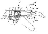
- FIG. 1is a partly cut-away view of a finger member of the prosthesis according to the present invention
- FIG. 2is a detailed view of the Proximal Intermediate Phalangeal (PIP) joint of FIG. 1 ;
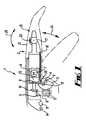
- FIG. 3is a detailed view of the bevel gear arrangement of the prosthesis of FIG. 1 .
- FIG. 1shows a partly cut-away view of a hand prosthesis 1 having a finger 3 (which constitutes a digit).
- the prosthesis 1is securely fixed in use to a patient's hand stump (not shown) in a generally known manner by means of a main body (not shown).
- the main bodyhas a spindle 4 on which a worm gear wheel 5 is fixedly mounted.
- Worm gear wheel 5is of roughly semi-circular profile.
- Finger 3extends generally tangentially with respect to worm gear wheel 5 .
- Finger 3has a generally tubular housing 6 , in which is mounted a drive motor 7 having a gearbox system 23 .
- the gearbox system 23provides for different torque—output drive speed ratios to be selected from a range of different ratios.
- Lugsdepend from the underside of the tubular housing 6 and are rotatably mounted on the spindle to allow for rotation of the finger 3 in relation to the spindle 4 and worm gear wheel 5 .
- the centre 8 of the spindle 4defines an axis (which constitutes a worm gear wheel means axis) about which the finger 3 rotates.
- the housing 6 containing the drive motor 7corresponds to the proximal phalanx of a finger and the joint formed between the spindle 4 and the lugs depending from the housing 6 correspond to the metacarpophalangeal (MCP) or knuckle joint of a finger.
- MCPmetacarpophalangeal
- a drive shaft 9extends from the drive motor 7 and gearbox system 23 .
- a first bevel gear 10is mounted on the distal end of the drive shaft 9 .
- a second bevel gear 11is mounted within the prosthesis 1 such that an axis of rotation of the second bevel gear 11 is at substantially 90 degrees to an axis of rotation of the first bevel gear 10 .
- First and second bevel gears 10 , 11together constitute transmission means.
- the gear ratio of the first and second bevel gears 10 , 11is substantially 1 to 1, although the gear ratio can be readily changed by known means.
- the second bevel gear 12is mounted on the same shaft 12 as a worm 13 .
- the worm 13is located such that it engages with a toothed curved peripheral edge of worm gear wheel 5 . As can be seen from FIG. 1 the worm 13 extends laterally to the housing 6 at an angle of about 90 degrees.
- the worm 13is located in the prosthesis such that it is outside the housing 6 (which corresponds to a digit member). Thus, the worm is located within the hand of the prosthesis and not the finger 3 even though the prosthesis is structured such that the worm 13 moves with the housing 6 upon operation of the finger 3 , as described below.
- the drive motor 7is a permanent magnet DC motor having a substantially linear relation between torque and drive current. Furthermore, the drive motor is powered by small rechargeable batteries 14 , which may be mounted remotely of the prosthesis.
- the drive motoris controlled by means of switches 15 (which constitutes control means), which are actuated by known means, e.g. residual digit movement or wrist movement. Alternatively or in addition, control may be by means of pressure sensitive resistors or signals derived from the electromyographic activity of residual muscle actions.
- control by known meansprovides for independence of movement of the digits or groups of digits. In the case of a finger the drive motor 7 has low speed, high torque characteristics and in the case of a thumb the drive motor has high speed. Low torque characteristics.
- Finger 3has a finger tip portion 16 corresponding to the middle and distal phalanges of a finger (and which constitutes a second digit member), which forms with the distal end of the housing 6 a proximal joint 17 corresponding to a proximal intermediate phalangeal (PIP) joint of a finger.
- Arrow 24represents movement of the finger 3 about axis 8 (i.e. the MCP joint) and arrow 26 represents movement of finger tip portion 16 about PIP joint 17 .
- a toothed inextensible belt 18is attached at a first end to the worm gear wheel 5 in an aperture 19 provided in the worm gear wheel 5 , passes over a protrusion 20 formed on the worm gear wheel and is attached at a second end to the finger tip portion 16 .
- a helical spring 22(which constitutes a biasing means) is connected at one end to the end of housing 6 and at a second opposing end to the finger tip portion 16 .
- the prosthesisis clad with an overlay 21 of silicone rubber or the like to provide an aesthetically acceptable appearance as similar as practicable to a normal hand appearance in a known manner.
- FIG. 2is a detailed view of the PIP joint 17 of FIG. 1 .
- the finger tip portion 16corresponds to the middle and distal phalanges of a finger.
- the toothed belt 18passes over a roller 30 mounted near the joint 17 before passing over a finger tip core 32 , which is a solid body formed from a plastics or metal and attached to the joint 17 .
- Finger tip core 32has indentations formed in its surface that are shaped to receive the teeth on the belt 18 and provide for engagement between finger tip core 32 and the belt 18 .
- the effective length of the belt 18can be adjusted by a graduated amount corresponding to the spacing of the teeth on the belt by disengaging the belt 18 from the finger tip core 32 and moving the belt in the requisite direction before re-engaging belt and finger tip core.
- a cover 34is located over the distal portion of the finger and secured by means of screws 36 to sandwich the belt 18 between the cover 34 and the finger tip core 32 .
- FIG. 3provides a detailed view of the bevel gears of the prosthesis.
- the prosthesiscomprises a bevel support member 42 having three limbs 44 , 46 , 48 , with second and third limbs 46 , 48 disposed perpendicularly to the first limb 44 , thereby forming a double l-shape in profile, with the worm 13 disposed between the second and third limbs 46 , 48 .
- the first limb 44is attached to the housing 6 of the prosthesis.
- the shaft of the first bevel gear 10passes through an aperture provide in the first limb 44 of the bevel support member 42 and the shaft of the second bevel gear 11 passes through an aperture provided in the second limb 46 of the bevel support member.
- the l-shaped bevel support membersupports the first and second bevel gears 10 , 11 and the worm 13 and provides for ease of relative location of the first and second bevel gears 10 , 11 during assembly of the prosthesis.
- the bevel support member 42has a large single limb instead of the second and third limbs 46 , 48 shown in FIG. 3 .
- the large single limb of the alternative form of bevel support member 42defines a bore in which the worm 13 is supported.
- the large single limbis formed such that it supports the shaft of the second bevel gear 11 and the shaft of the worm 13 in much the same fashion as shown in and described with reference to FIG. 3 .
- the weareractuates the finger by means of the control means described above, which provides for operation of the drive motor 7 .
- Operation of drive motor 7causes rotation of the first bevel gear 10 , which rotates the second bevel gear 11 along with the worm 13 .
- worm 13rotates it progresses around the peripheral surface of fixed worm gear wheel 5 either clockwise or anti-clockwise depending on the direction of rotation of drive motor 7 .
- Thismoves the finger 3 about axis 8 as indicated by arrow 24 .
- finger 3moves about axis 8 in a downward direction the distance between the point of attachment of toothed belt 18 in aperture 19 of the worm gear wheel 5 and the proximal joint 17 reduces.
- aperture 19is offset from the axis of the worm gear wheel as shown in FIG. 1 .
- the fixed length toothed belt 18pulls on the finger tip portion 16 against the bias of the helical spring 22 to rotate the finger tip portion 16 clockwise in relation to the rest of the finger 3 .
- tensionis released on the toothed belt 18 and the spring 22 exerts a bias on the finger tip portion 16 to return the finger tip portion to the extended position shown in FIG. 1 .
Landscapes
- Health & Medical Sciences (AREA)
- Transplantation (AREA)
- Orthopedic Medicine & Surgery (AREA)
- Animal Behavior & Ethology (AREA)
- Public Health (AREA)
- Engineering & Computer Science (AREA)
- Biomedical Technology (AREA)
- Heart & Thoracic Surgery (AREA)
- Vascular Medicine (AREA)
- Life Sciences & Earth Sciences (AREA)
- Cardiology (AREA)
- General Health & Medical Sciences (AREA)
- Oral & Maxillofacial Surgery (AREA)
- Veterinary Medicine (AREA)
- Prostheses (AREA)
- Materials For Medical Uses (AREA)
- Manipulator (AREA)
- Finger-Pressure Massage (AREA)
- Rehabilitation Tools (AREA)
- Push-Button Switches (AREA)
Abstract
Description
Claims (12)
Applications Claiming Priority (3)
| Application Number | Priority Date | Filing Date | Title |
|---|---|---|---|
| GB052484.7 | 2005-11-29 | ||
| GBGB0524284.7AGB0524284D0 (en) | 2005-11-29 | 2005-11-29 | Prosthesis |
| PCT/GB2006/002680WO2007063266A1 (en) | 2005-11-29 | 2006-07-19 | Prostheses with mechanically operable digit members |
Publications (2)
| Publication Number | Publication Date |
|---|---|
| US20100036507A1 US20100036507A1 (en) | 2010-02-11 |
| US8808397B2true US8808397B2 (en) | 2014-08-19 |
Family
ID=35601431
Family Applications (1)
| Application Number | Title | Priority Date | Filing Date |
|---|---|---|---|
| US12/085,608Active2029-05-06US8808397B2 (en) | 2005-11-29 | 2006-07-16 | Prostheses with mechanically operable digit members |
Country Status (10)
| Country | Link |
|---|---|
| US (1) | US8808397B2 (en) |
| EP (2) | EP1962731B1 (en) |
| JP (1) | JP4841633B2 (en) |
| CN (1) | CN101321508B (en) |
| AT (2) | ATE447381T1 (en) |
| DE (1) | DE602006010239D1 (en) |
| DK (2) | DK2135588T3 (en) |
| ES (2) | ES2336027T3 (en) |
| GB (1) | GB0524284D0 (en) |
| WO (1) | WO2007063266A1 (en) |
Cited By (20)
| Publication number | Priority date | Publication date | Assignee | Title |
|---|---|---|---|---|
| US20150351935A1 (en)* | 2013-01-16 | 2015-12-10 | Fabrica Machinale S.R.L. | Prosthetic hand system |
| US9974667B1 (en) | 2015-05-28 | 2018-05-22 | Blain Joseph Cazenave | Electromagnetic actuation mechanism for individual digit control of an artificial hand |
| US20180263791A1 (en)* | 2015-11-18 | 2018-09-20 | Zorpia Robot Co. Ltd | Prosthetic thumb |
| US10260566B2 (en) | 2015-05-13 | 2019-04-16 | Mark H. Salerno | Marine antenna actuator |
| US10265197B2 (en) | 2014-05-09 | 2019-04-23 | Touch Bionics Limited | Systems and methods for controlling a prosthetic hand |
| US10369024B2 (en) | 2016-09-02 | 2019-08-06 | Touch Bionics Limited | Systems and methods for prosthetic wrist rotation |
| US10369016B2 (en) | 2014-02-04 | 2019-08-06 | Rehabilitation Institute Of Chicago | Modular and lightweight myoelectric prosthesis components and related methods |
| US10398576B2 (en) | 2011-08-18 | 2019-09-03 | Touch Bionics Limited | Prosthetic feedback apparatus and method |
| US10449063B2 (en) | 2014-10-03 | 2019-10-22 | Touch Bionics Limited | Wrist device for a prosthetic limb |
| US10610385B2 (en) | 2013-02-05 | 2020-04-07 | Touch Bionics Limited | Multi-modal upper limb prosthetic device control using myoelectric signals |
| US10973660B2 (en) | 2017-12-15 | 2021-04-13 | Touch Bionics Limited | Powered prosthetic thumb |
| WO2021124060A1 (en) | 2019-12-19 | 2021-06-24 | Touch Bionics Limited | Electromyography and motion based control of upper limb prosthetics |
| US11083600B2 (en) | 2014-02-25 | 2021-08-10 | Touch Bionics Limited | Prosthetic digit for use with touchscreen devices |
| US11185426B2 (en) | 2016-09-02 | 2021-11-30 | Touch Bionics Limited | Systems and methods for prosthetic wrist rotation |
| US11351042B2 (en) | 2012-08-12 | 2022-06-07 | 5Th Element Limited | Automated hand |
| US11931270B2 (en) | 2019-11-15 | 2024-03-19 | Touch Bionics Limited | Prosthetic digit actuator |
| WO2024184814A2 (en) | 2023-03-07 | 2024-09-12 | Touch Bionics Limited | Prosthetic thumb with rotation and compound flexion |
| US12115087B2 (en) | 2020-11-03 | 2024-10-15 | Touch Bionics Limited | Sensor for prosthetic control |
| US12279977B2 (en) | 2018-12-20 | 2025-04-22 | Touch Bionics Limited | Energy conservation of a motor-driven digit |
| US12427040B2 (en) | 2019-04-10 | 2025-09-30 | Touch Bionics Limited | Prosthetic digit with articulating links |
Families Citing this family (41)
| Publication number | Priority date | Publication date | Assignee | Title |
|---|---|---|---|---|
| US8956421B2 (en) | 2007-02-06 | 2015-02-17 | Deka Products Limited Partnership | Dynamic support apparatus and system |
| GB0524284D0 (en) | 2005-11-29 | 2006-01-04 | Touch Emas Ltd | Prosthesis |
| US9114028B2 (en)* | 2007-02-06 | 2015-08-25 | Deka Products Limited Partnership | Arm prosthetic device |
| WO2008098053A1 (en) | 2007-02-06 | 2008-08-14 | Deka Integrated Solutions Corp. | Dynamic support apparatus |
| US8864845B2 (en) | 2007-02-06 | 2014-10-21 | DEKA Limited Partnership | System for control of a prosthetic device |
| WO2008098059A2 (en) | 2007-02-06 | 2008-08-14 | Deka Integrated Solutions Corp. | Method and apparatus for control of a prosthetic |
| US9114030B2 (en) | 2007-02-06 | 2015-08-25 | Deka Products Limited Partnership | System for control of a prosthetic device |
| US11291562B2 (en) | 2007-02-06 | 2022-04-05 | Deka Products Limited Partnership | Arm prosthetic device |
| DE102008056520B4 (en) | 2008-11-08 | 2017-10-19 | Stefan Schulz | finger member |
| GB0910920D0 (en) | 2009-06-24 | 2009-08-05 | Touch Emas Ltd | Method of controlling a prosthesis |
| GB0916895D0 (en) | 2009-09-25 | 2009-11-11 | Touch Emas Ltd | Prosthetic apparatus and method |
| PL221882B1 (en) | 2010-01-14 | 2016-06-30 | Michał Wasielewski | Modular human hand prosthesis with modular, mechanically independent finger modules |
| DE102010005690B4 (en)* | 2010-01-25 | 2012-04-19 | Otto Bock Healthcare Products Gmbh | Adjusting device for a prosthetic device and method for operating such an adjusting device |
| GB201003573D0 (en) | 2010-03-04 | 2010-04-21 | Touch Emas Ltd | Hand prothesis |
| JP5795171B2 (en)* | 2011-03-04 | 2015-10-14 | 株式会社ツバキE&M | Reduction gear and its series |
| DE102011110101A1 (en) | 2011-08-13 | 2013-02-14 | Stefan Schulz | Method for moving and holding a phalanx |
| GB201116060D0 (en) | 2011-09-16 | 2011-11-02 | Touch Emas Ltd | Method of controlling a prosthesis |
| GB201116069D0 (en) | 2011-09-16 | 2011-11-02 | Touch Emas Ltd | Method and apparatus for controlling a prosthetic device |
| DE102011116751A1 (en)* | 2011-10-24 | 2013-04-25 | Fraunhofer-Gesellschaft zur Förderung der angewandten Forschung e.V. | Active knee prosthesis with bevel helical gear |
| GB201213030D0 (en) | 2012-07-23 | 2012-09-05 | Touch Emas Ltd | Improvements in or relating to prosthetics and orthotics |
| JP5655877B2 (en)* | 2013-02-12 | 2015-01-21 | 株式会社安川電機 | Joint mechanism and robot |
| DE102013007539A1 (en)* | 2013-05-03 | 2014-11-06 | Otto Bock Healthcare Products Gmbh | Artificial finger |
| JP6640830B2 (en) | 2014-07-18 | 2020-02-05 | ベクトン・ディキンソン・アンド・カンパニーBecton, Dickinson And Company | Lancet device for removing first droplet |
| CN104625798A (en)* | 2014-12-09 | 2015-05-20 | 重庆迪科汽车研究有限公司 | Three-sided stable clamping mechanism |
| US20160367383A1 (en)* | 2015-06-19 | 2016-12-22 | Rehabilitation Institute Of Chicago | Lockable Finger System and Related Methods |
| CN105078624A (en)* | 2015-09-06 | 2015-11-25 | 丹阳假肢厂有限公司 | Electric two-dimensional bionic hand thumb |
| CN105232192A (en)* | 2015-09-06 | 2016-01-13 | 丹阳假肢厂有限公司 | Middle and index finger structure of bionic hand |
| CN106038008B (en)* | 2015-11-18 | 2018-03-02 | 杭州若比邻机器人科技有限公司 | The base finger joint of artificial limb finger and the attachment structure in base joint |
| CN105584554B (en)* | 2015-12-17 | 2018-05-04 | 常州大学 | Anthropomorphic robot two-freedom series-parallel connection vibration damping machinery foot |
| CN105965535B (en)* | 2016-05-04 | 2019-01-18 | 上海科生假肢有限公司 | Bionic hand carpomaetacarpal joint of thumb |
| DE102017005762B4 (en) | 2017-06-20 | 2020-02-13 | Stefan Schulz | finger member |
| CN108214537B (en)* | 2018-02-02 | 2023-07-18 | 昆明理工大学 | A Multifunctional and Flexible Grabbing Mechanism |
| US11185427B2 (en) | 2018-04-27 | 2021-11-30 | Psyonic, Inc. | Compliant four-bar linkage mechanism for a robotic finger |
| GB2577499B (en)* | 2018-09-25 | 2020-11-18 | Covvi Ltd | A mechanical hand |
| WO2020106728A1 (en) | 2018-11-19 | 2020-05-28 | The Regents Of The University Of Colorado, A Body Corporate | Prosthetic partial fingers |
| CN109758275B (en)* | 2019-01-22 | 2023-11-10 | 内蒙古恩德莱康复器具有限公司 | Combined under-actuated bionic artificial finger with driving rope and four-bar mechanism |
| RU2719658C1 (en)* | 2019-02-20 | 2020-04-21 | Общество с ограниченной ответственностью "МОТОРИКА" | Gripping mechanism of pedicle single-seam bioelectric prosthesis of upper limb |
| US11399967B2 (en) | 2019-03-29 | 2022-08-02 | Psyonic, Inc. | System and method for a prosthetic hand having sensored brushless motors |
| EP4042982B1 (en) | 2021-02-10 | 2024-05-29 | Point Designs LLC | Prosthetic thumb device |
| WO2022174087A1 (en) | 2021-02-11 | 2022-08-18 | Psyonic, Inc. | System and method for an artificial tendon-driven prosthesis |
| CN117323074B (en)* | 2023-12-01 | 2024-03-29 | 中国科学技术大学 | A wearable prosthetic glove control method and system |
Citations (19)
| Publication number | Priority date | Publication date | Assignee | Title |
|---|---|---|---|---|
| DE309367C (en) | ||||
| US2592842A (en) | 1948-07-10 | 1952-04-15 | Samuel W Alderson | Shoulder harness for artificial arms |
| US3509583A (en) | 1965-09-09 | 1970-05-05 | Bendix Corp | Electro-mechanical hand having tactile sensing means |
| US3683423A (en) | 1971-01-19 | 1972-08-15 | Russell S Crapanzano | Gravity activated prosthetic device |
| US3837010A (en)* | 1972-03-16 | 1974-09-24 | Parke Davis & Co | Prosthetic elbow with resilient locking assembly |
| US3922930A (en)* | 1974-12-23 | 1975-12-02 | Nasa | Remotely operable articulated manipulator |
| GB1510298A (en) | 1976-02-25 | 1978-05-10 | Messerschmitt Boelkow Blohm | Artificial hands |
| US4623354A (en) | 1984-10-22 | 1986-11-18 | Northwestern University | Myoelectrically controlled artificial hand |
| US4822238A (en)* | 1986-06-19 | 1989-04-18 | Westinghouse Electric Corp. | Robotic arm |
| US4955918A (en) | 1989-05-30 | 1990-09-11 | University Of Southern California | Artificial dexterous hand |
| US5062673A (en)* | 1988-12-28 | 1991-11-05 | Kabushiki Kaisha Toyota Chuo Kenkyusho | Articulated hand |
| WO1995024875A1 (en) | 1994-03-12 | 1995-09-21 | Royal Infirmary Of Edinburgh Nhs Trust | Hand prosthesis |
| DE19854762A1 (en) | 1998-11-27 | 2000-06-15 | Marc Franke | Artificial hand with two or more fingers for picking up objects includes distal finger section connected by tilting movement to medial section by distal articulated joint, and medial to proximal by medial joint |
| US6361570B1 (en) | 1997-10-24 | 2002-03-26 | Lothian Primary Care Nhs Trust | Upper limb prosthesis |
| US6660043B2 (en)* | 2002-04-16 | 2003-12-09 | National Institute Of Advanced Industrial Science And Technology | Artificial hand |
| US20050021154A1 (en)* | 2001-08-27 | 2005-01-27 | Stellan Brimalm | Drive device for a finger prosthesis |
| US20050021155A1 (en) | 2001-08-27 | 2005-01-27 | Stellan Brimalm | Device at a hand prosthesis |
| WO2007063266A1 (en) | 2005-11-29 | 2007-06-07 | Touch Emas Limited | Prostheses with mechanically operable digit members |
| US20080262634A1 (en)* | 2005-12-20 | 2008-10-23 | Otto Bock Healthcare Ip Gmbh & Co. Kg | Hand Prosthesis Comprising Two Drive Devices |
Family Cites Families (2)
| Publication number | Priority date | Publication date | Assignee | Title |
|---|---|---|---|---|
| JPS5128872Y1 (en)* | 1970-08-26 | 1976-07-21 | ||
| JP2648230B2 (en)* | 1990-09-20 | 1997-08-27 | 科学技術振興事業団 | manipulator |
- 2005
- 2005-11-29GBGBGB0524284.7Apatent/GB0524284D0/ennot_activeCeased
- 2006
- 2006-07-16USUS12/085,608patent/US8808397B2/enactiveActive
- 2006-07-19DKDK09012179.9Tpatent/DK2135588T3/enactive
- 2006-07-19DKDK06765015.0Tpatent/DK1962731T3/enactive
- 2006-07-19ATAT06765015Tpatent/ATE447381T1/ennot_activeIP Right Cessation
- 2006-07-19DEDE602006010239Tpatent/DE602006010239D1/enactiveActive
- 2006-07-19WOPCT/GB2006/002680patent/WO2007063266A1/enactiveApplication Filing
- 2006-07-19EPEP06765015Apatent/EP1962731B1/enactiveActive
- 2006-07-19EPEP09012179Apatent/EP2135588B1/enactiveActive
- 2006-07-19ESES06765015Tpatent/ES2336027T3/enactiveActive
- 2006-07-19JPJP2008542815Apatent/JP4841633B2/ennot_activeExpired - Fee Related
- 2006-07-19ATAT09012179Tpatent/ATE525042T1/ennot_activeIP Right Cessation
- 2006-07-19CNCN2006800447184Apatent/CN101321508B/enactiveActive
- 2006-07-19ESES09012179Tpatent/ES2373847T3/enactiveActive
Patent Citations (21)
| Publication number | Priority date | Publication date | Assignee | Title |
|---|---|---|---|---|
| DE309367C (en) | ||||
| US2592842A (en) | 1948-07-10 | 1952-04-15 | Samuel W Alderson | Shoulder harness for artificial arms |
| US3509583A (en) | 1965-09-09 | 1970-05-05 | Bendix Corp | Electro-mechanical hand having tactile sensing means |
| US3683423A (en) | 1971-01-19 | 1972-08-15 | Russell S Crapanzano | Gravity activated prosthetic device |
| US3837010A (en)* | 1972-03-16 | 1974-09-24 | Parke Davis & Co | Prosthetic elbow with resilient locking assembly |
| US3922930A (en)* | 1974-12-23 | 1975-12-02 | Nasa | Remotely operable articulated manipulator |
| GB1510298A (en) | 1976-02-25 | 1978-05-10 | Messerschmitt Boelkow Blohm | Artificial hands |
| US4114464A (en)* | 1976-02-25 | 1978-09-19 | Messerschmitt-Bolkow-Blohm Gesellschaft Mit Beschrankter Haftung | Artificial hand and drive apparatus for such hand |
| US4623354A (en) | 1984-10-22 | 1986-11-18 | Northwestern University | Myoelectrically controlled artificial hand |
| US4822238A (en)* | 1986-06-19 | 1989-04-18 | Westinghouse Electric Corp. | Robotic arm |
| US5062673A (en)* | 1988-12-28 | 1991-11-05 | Kabushiki Kaisha Toyota Chuo Kenkyusho | Articulated hand |
| US4955918A (en) | 1989-05-30 | 1990-09-11 | University Of Southern California | Artificial dexterous hand |
| WO1995024875A1 (en) | 1994-03-12 | 1995-09-21 | Royal Infirmary Of Edinburgh Nhs Trust | Hand prosthesis |
| US5888246A (en)* | 1994-03-12 | 1999-03-30 | Royal Infirmary Of Edinburgh Nhs Trust | Motor drive system and linkage for hand prosthesis |
| US6361570B1 (en) | 1997-10-24 | 2002-03-26 | Lothian Primary Care Nhs Trust | Upper limb prosthesis |
| DE19854762A1 (en) | 1998-11-27 | 2000-06-15 | Marc Franke | Artificial hand with two or more fingers for picking up objects includes distal finger section connected by tilting movement to medial section by distal articulated joint, and medial to proximal by medial joint |
| US20050021154A1 (en)* | 2001-08-27 | 2005-01-27 | Stellan Brimalm | Drive device for a finger prosthesis |
| US20050021155A1 (en) | 2001-08-27 | 2005-01-27 | Stellan Brimalm | Device at a hand prosthesis |
| US6660043B2 (en)* | 2002-04-16 | 2003-12-09 | National Institute Of Advanced Industrial Science And Technology | Artificial hand |
| WO2007063266A1 (en) | 2005-11-29 | 2007-06-07 | Touch Emas Limited | Prostheses with mechanically operable digit members |
| US20080262634A1 (en)* | 2005-12-20 | 2008-10-23 | Otto Bock Healthcare Ip Gmbh & Co. Kg | Hand Prosthesis Comprising Two Drive Devices |
Cited By (32)
| Publication number | Priority date | Publication date | Assignee | Title |
|---|---|---|---|---|
| US10398576B2 (en) | 2011-08-18 | 2019-09-03 | Touch Bionics Limited | Prosthetic feedback apparatus and method |
| US11259941B2 (en) | 2011-08-18 | 2022-03-01 | Touch Bionics Limited | Prosthetic feedback apparatus and method |
| US12090068B2 (en) | 2012-08-12 | 2024-09-17 | 5Th Element Limited | Automated hand |
| US11351042B2 (en) | 2012-08-12 | 2022-06-07 | 5Th Element Limited | Automated hand |
| US12161569B2 (en) | 2013-01-16 | 2024-12-10 | Fabrica Machinale S.R.L. | Prosthetic hand system |
| US10583017B2 (en)* | 2013-01-16 | 2020-03-10 | Epica International, Inc. | Prosthetic hand system |
| US20150351935A1 (en)* | 2013-01-16 | 2015-12-10 | Fabrica Machinale S.R.L. | Prosthetic hand system |
| US11890208B2 (en) | 2013-02-05 | 2024-02-06 | Touch Bionics Limited | Multi-modal upper limb prosthetic device control using myoelectric signals |
| US10610385B2 (en) | 2013-02-05 | 2020-04-07 | Touch Bionics Limited | Multi-modal upper limb prosthetic device control using myoelectric signals |
| US10369016B2 (en) | 2014-02-04 | 2019-08-06 | Rehabilitation Institute Of Chicago | Modular and lightweight myoelectric prosthesis components and related methods |
| US11464654B2 (en) | 2014-02-04 | 2022-10-11 | Rehabilitation Institute Of Chicago | Modular and lightweight myoelectric prosthesis components and related methods |
| US11083600B2 (en) | 2014-02-25 | 2021-08-10 | Touch Bionics Limited | Prosthetic digit for use with touchscreen devices |
| US10265197B2 (en) | 2014-05-09 | 2019-04-23 | Touch Bionics Limited | Systems and methods for controlling a prosthetic hand |
| US11234842B2 (en) | 2014-05-09 | 2022-02-01 | Touch Bionics Limited | Systems and methods for controlling a prosthetic hand |
| US10449063B2 (en) | 2014-10-03 | 2019-10-22 | Touch Bionics Limited | Wrist device for a prosthetic limb |
| US12097131B2 (en) | 2014-10-03 | 2024-09-24 | Touch Bionics Limited | Wrist device for a prosthetic limb |
| US11357646B2 (en) | 2014-10-03 | 2022-06-14 | Touch Bionics Limited | Wrist device for a prosthetic limb |
| US10260566B2 (en) | 2015-05-13 | 2019-04-16 | Mark H. Salerno | Marine antenna actuator |
| US9974667B1 (en) | 2015-05-28 | 2018-05-22 | Blain Joseph Cazenave | Electromagnetic actuation mechanism for individual digit control of an artificial hand |
| US10675160B2 (en)* | 2015-11-18 | 2020-06-09 | Jinshi BAI | Prosthetic thumb |
| US20180263791A1 (en)* | 2015-11-18 | 2018-09-20 | Zorpia Robot Co. Ltd | Prosthetic thumb |
| US10369024B2 (en) | 2016-09-02 | 2019-08-06 | Touch Bionics Limited | Systems and methods for prosthetic wrist rotation |
| US12059362B2 (en) | 2016-09-02 | 2024-08-13 | Touch Bionics Limited | Systems and methods for prosthetic wrist rotation |
| US11185426B2 (en) | 2016-09-02 | 2021-11-30 | Touch Bionics Limited | Systems and methods for prosthetic wrist rotation |
| US11786381B2 (en) | 2017-12-15 | 2023-10-17 | Touch Bionics Limited | Powered prosthetic thumb |
| US10973660B2 (en) | 2017-12-15 | 2021-04-13 | Touch Bionics Limited | Powered prosthetic thumb |
| US12279977B2 (en) | 2018-12-20 | 2025-04-22 | Touch Bionics Limited | Energy conservation of a motor-driven digit |
| US12427040B2 (en) | 2019-04-10 | 2025-09-30 | Touch Bionics Limited | Prosthetic digit with articulating links |
| US11931270B2 (en) | 2019-11-15 | 2024-03-19 | Touch Bionics Limited | Prosthetic digit actuator |
| WO2021124060A1 (en) | 2019-12-19 | 2021-06-24 | Touch Bionics Limited | Electromyography and motion based control of upper limb prosthetics |
| US12115087B2 (en) | 2020-11-03 | 2024-10-15 | Touch Bionics Limited | Sensor for prosthetic control |
| WO2024184814A2 (en) | 2023-03-07 | 2024-09-12 | Touch Bionics Limited | Prosthetic thumb with rotation and compound flexion |
Also Published As
| Publication number | Publication date |
|---|---|
| JP2009517155A (en) | 2009-04-30 |
| DK2135588T3 (en) | 2012-01-23 |
| EP2135588A2 (en) | 2009-12-23 |
| DK1962731T3 (en) | 2010-03-22 |
| CN101321508B (en) | 2011-03-23 |
| EP1962731B1 (en) | 2009-11-04 |
| ATE447381T1 (en) | 2009-11-15 |
| ES2373847T3 (en) | 2012-02-09 |
| EP2135588A9 (en) | 2010-02-24 |
| JP4841633B2 (en) | 2011-12-21 |
| EP2135588A3 (en) | 2009-12-30 |
| DE602006010239D1 (en) | 2009-12-17 |
| ES2336027T3 (en) | 2010-04-07 |
| US20100036507A1 (en) | 2010-02-11 |
| CN101321508A (en) | 2008-12-10 |
| ATE525042T1 (en) | 2011-10-15 |
| EP1962731A1 (en) | 2008-09-03 |
| WO2007063266A1 (en) | 2007-06-07 |
| EP2135588B1 (en) | 2011-09-21 |
| GB0524284D0 (en) | 2006-01-04 |
Similar Documents
| Publication | Publication Date | Title |
|---|---|---|
| US8808397B2 (en) | Prostheses with mechanically operable digit members | |
| EP2542189B1 (en) | Hand prosthesis | |
| US5888246A (en) | Motor drive system and linkage for hand prosthesis | |
| EP2445455B1 (en) | Method of controlling a prosthesis | |
| ES2928990T3 (en) | mechanical hand | |
| ES2928960T3 (en) | mechanical hand | |
| US20140288665A1 (en) | Prosthesis or an orthosis and a method for controlling a prosthesis or an orthosis | |
| WO2020065266A1 (en) | A mechanical hand | |
| US12042931B2 (en) | Mechanical hand | |
| US20240299192A1 (en) | Prosthetic thumb with rotation and compound flexion | |
| CA2184985C (en) | Hand prosthesis |
Legal Events
| Date | Code | Title | Description |
|---|---|---|---|
| AS | Assignment | Owner name:CLYDESDALE BANK PLC, UNITED KINGDOM Free format text:SECURITY AGREEMENT;ASSIGNOR:TOUCH EMAS LIMITED;REEL/FRAME:026133/0674 Effective date:20110405 | |
| AS | Assignment | Owner name:TOUCH EMAS LIMITED, UNITED KINGDOM Free format text:ASSIGNMENT OF ASSIGNORS INTEREST;ASSIGNOR:GOW, DAVID JAMES;REEL/FRAME:026749/0380 Effective date:20110801 | |
| STCF | Information on status: patent grant | Free format text:PATENTED CASE | |
| FEPP | Fee payment procedure | Free format text:PAT HOLDER NO LONGER CLAIMS SMALL ENTITY STATUS, ENTITY STATUS SET TO UNDISCOUNTED (ORIGINAL EVENT CODE: STOL); ENTITY STATUS OF PATENT OWNER: LARGE ENTITY | |
| AS | Assignment | Owner name:TOUCH BIONICS LIMITED, UNITED KINGDOM Free format text:CHANGE OF NAME;ASSIGNOR:TOUCH EMAS LIMITED;REEL/FRAME:044548/0436 Effective date:20140613 | |
| MAFP | Maintenance fee payment | Free format text:PAYMENT OF MAINTENANCE FEE, 4TH YEAR, LARGE ENTITY (ORIGINAL EVENT CODE: M1551) Year of fee payment:4 | |
| AS | Assignment | Owner name:TOUCH BIONICS LIMITED, GREAT BRITAIN Free format text:ASSIGNEE CHANGE OF ADDRESS;ASSIGNOR:TOUCH BIONICS LIMITED;REEL/FRAME:052456/0182 Effective date:20200417 | |
| MAFP | Maintenance fee payment | Free format text:PAYMENT OF MAINTENANCE FEE, 8TH YEAR, LARGE ENTITY (ORIGINAL EVENT CODE: M1552); ENTITY STATUS OF PATENT OWNER: LARGE ENTITY Year of fee payment:8 |