US8808307B2 - Driver for a surgical device - Google Patents
Driver for a surgical deviceDownload PDFInfo
- Publication number
- US8808307B2 US8808307B2US13/272,931US201113272931AUS8808307B2US 8808307 B2US8808307 B2US 8808307B2US 201113272931 AUS201113272931 AUS 201113272931AUS 8808307 B2US8808307 B2US 8808307B2
- Authority
- US
- United States
- Prior art keywords
- tool
- drive
- head portion
- locking
- locking portions
- Prior art date
- Legal status (The legal status is an assumption and is not a legal conclusion. Google has not performed a legal analysis and makes no representation as to the accuracy of the status listed.)
- Active
Links
- 239000007943implantSubstances0.000claimsabstractdescription15
- 230000007246mechanismEffects0.000claimsabstractdescription15
- 210000000988bone and boneAnatomy0.000claimsdescription17
- 230000013011matingEffects0.000claimsdescription8
- 230000004323axial lengthEffects0.000claimsdescription5
- 230000008878couplingEffects0.000description10
- 238000010168coupling processMethods0.000description10
- 238000005859coupling reactionMethods0.000description10
- 230000000712assemblyEffects0.000description4
- 238000000429assemblyMethods0.000description4
- 238000003780insertionMethods0.000description3
- 230000037431insertionEffects0.000description3
- 239000000463materialSubstances0.000description3
- 238000000926separation methodMethods0.000description3
- RTAQQCXQSZGOHL-UHFFFAOYSA-NTitaniumChemical compound[Ti]RTAQQCXQSZGOHL-UHFFFAOYSA-N0.000description2
- 230000004075alterationEffects0.000description2
- 238000002788crimpingMethods0.000description2
- 238000012986modificationMethods0.000description2
- 230000004048modificationEffects0.000description2
- 239000010936titaniumSubstances0.000description2
- 229910001200FerrotitaniumInorganic materials0.000description1
- 230000009471actionEffects0.000description1
- 230000009286beneficial effectEffects0.000description1
- 230000008901benefitEffects0.000description1
- 230000002452interceptive effectEffects0.000description1
- 229910001220stainless steelInorganic materials0.000description1
- 239000010935stainless steelSubstances0.000description1
- 238000001356surgical procedureMethods0.000description1
- 229910052719titaniumInorganic materials0.000description1
- 238000003466weldingMethods0.000description1
Images


Classifications
- A—HUMAN NECESSITIES
- A61—MEDICAL OR VETERINARY SCIENCE; HYGIENE
- A61B—DIAGNOSIS; SURGERY; IDENTIFICATION
- A61B17/00—Surgical instruments, devices or methods
- A61B17/56—Surgical instruments or methods for treatment of bones or joints; Devices specially adapted therefor
- A61B17/58—Surgical instruments or methods for treatment of bones or joints; Devices specially adapted therefor for osteosynthesis, e.g. bone plates, screws or setting implements
- A61B17/88—Osteosynthesis instruments; Methods or means for implanting or extracting internal or external fixation devices
- A61B17/8875—Screwdrivers, spanners or wrenches
- A61B17/8886—Screwdrivers, spanners or wrenches holding the screw head
- A61B17/8888—Screwdrivers, spanners or wrenches holding the screw head at its central region
- A—HUMAN NECESSITIES
- A61—MEDICAL OR VETERINARY SCIENCE; HYGIENE
- A61B—DIAGNOSIS; SURGERY; IDENTIFICATION
- A61B17/00—Surgical instruments, devices or methods
- A61B17/56—Surgical instruments or methods for treatment of bones or joints; Devices specially adapted therefor
- A61B17/58—Surgical instruments or methods for treatment of bones or joints; Devices specially adapted therefor for osteosynthesis, e.g. bone plates, screws or setting implements
- A61B17/68—Internal fixation devices, including fasteners and spinal fixators, even if a part thereof projects from the skin
- A61B17/70—Spinal positioners or stabilisers, e.g. stabilisers comprising fluid filler in an implant
- A61B17/7001—Screws or hooks combined with longitudinal elements which do not contact vertebrae
- A61B17/7032—Screws or hooks with U-shaped head or back through which longitudinal rods pass
- A—HUMAN NECESSITIES
- A61—MEDICAL OR VETERINARY SCIENCE; HYGIENE
- A61B—DIAGNOSIS; SURGERY; IDENTIFICATION
- A61B17/00—Surgical instruments, devices or methods
- A61B17/56—Surgical instruments or methods for treatment of bones or joints; Devices specially adapted therefor
- A61B17/58—Surgical instruments or methods for treatment of bones or joints; Devices specially adapted therefor for osteosynthesis, e.g. bone plates, screws or setting implements
- A61B17/68—Internal fixation devices, including fasteners and spinal fixators, even if a part thereof projects from the skin
- A61B17/70—Spinal positioners or stabilisers, e.g. stabilisers comprising fluid filler in an implant
- A61B17/7074—Tools specially adapted for spinal fixation operations other than for bone removal or filler handling
- A61B17/7091—Tools specially adapted for spinal fixation operations other than for bone removal or filler handling for applying, tightening or removing longitudinal element-to-bone anchor locking elements, e.g. caps, set screws, nuts or wedges
- A—HUMAN NECESSITIES
- A61—MEDICAL OR VETERINARY SCIENCE; HYGIENE
- A61B—DIAGNOSIS; SURGERY; IDENTIFICATION
- A61B17/00—Surgical instruments, devices or methods
- A61B17/56—Surgical instruments or methods for treatment of bones or joints; Devices specially adapted therefor
- A61B17/58—Surgical instruments or methods for treatment of bones or joints; Devices specially adapted therefor for osteosynthesis, e.g. bone plates, screws or setting implements
- A61B17/68—Internal fixation devices, including fasteners and spinal fixators, even if a part thereof projects from the skin
- A61B17/80—Cortical plates, i.e. bone plates; Instruments for holding or positioning cortical plates, or for compressing bones attached to cortical plates
- A61B17/808—Instruments for holding or positioning bone plates, or for adjusting screw-to-plate locking mechanisms
- A—HUMAN NECESSITIES
- A61—MEDICAL OR VETERINARY SCIENCE; HYGIENE
- A61B—DIAGNOSIS; SURGERY; IDENTIFICATION
- A61B17/00—Surgical instruments, devices or methods
- A61B17/56—Surgical instruments or methods for treatment of bones or joints; Devices specially adapted therefor
- A61B17/58—Surgical instruments or methods for treatment of bones or joints; Devices specially adapted therefor for osteosynthesis, e.g. bone plates, screws or setting implements
- A61B17/68—Internal fixation devices, including fasteners and spinal fixators, even if a part thereof projects from the skin
- A61B17/80—Cortical plates, i.e. bone plates; Instruments for holding or positioning cortical plates, or for compressing bones attached to cortical plates
- A—HUMAN NECESSITIES
- A61—MEDICAL OR VETERINARY SCIENCE; HYGIENE
- A61B—DIAGNOSIS; SURGERY; IDENTIFICATION
- A61B17/00—Surgical instruments, devices or methods
- A61B17/56—Surgical instruments or methods for treatment of bones or joints; Devices specially adapted therefor
- A61B17/58—Surgical instruments or methods for treatment of bones or joints; Devices specially adapted therefor for osteosynthesis, e.g. bone plates, screws or setting implements
- A61B17/88—Osteosynthesis instruments; Methods or means for implanting or extracting internal or external fixation devices
- A61B17/8875—Screwdrivers, spanners or wrenches
- A61B17/8877—Screwdrivers, spanners or wrenches characterised by the cross-section of the driver bit
- A61B17/888—Screwdrivers, spanners or wrenches characterised by the cross-section of the driver bit the driver bit acting on the central region of the screw head
Definitions
- the inventionrelates to a driver for surgical devices and, more particularly, to a drive tool for a locking device of a pedicle screw assembly.
- Typical driver toolshave a drive head configured to mate with a drive recess of a threaded fastener to be driven by the tool. This is true with common hardware such as screw drivers and screws, as well as with hardware used in surgical devices such as with threaded locking caps for pedicle screw assemblies.
- common hardwaresuch as screw drivers and screws
- hardware used in surgical devicessuch as with threaded locking caps for pedicle screw assemblies.
- a tool for driving and/or holding an implant memberincluding an elongate shaft having a portion that has both a distal head portion such as a drive head portion and a securing mechanism or portion disposed back up along the shaft from the distal head portion.
- the implant membercan be various implants such as a threaded or non-threaded driven member, or a bone plate.
- the drive portioncan be provided at both ends of the tool shaft or at only one end thereof.
- the distal drive head portionis provided with a radial size that is smaller than that of the corresponding radial size of the securing mechanism. In this manner, the circumferential extent of the locking engagement between the driver tool securing mechanism and the driven member is maximized relative to the radial size of the drive head portion.
- the securing mechanismcan comprise a plurality of resilient leg members that extend axially along the tool shaft and generally about the distal drive head portion thereof which projects beyond the ends of the resilient leg members.
- the leg memberscan have distal end locking portions that cooperate with structure of the driven member so that with the drive head portion of the tool shaft received in the corresponding drive recess of the driven member, the leg member locking portions will be secured to the driven member structure so that the driven member is positively held to the tool shaft against falling off therefrom.
- the inventionin another aspect, relates to a drive system which includes both the drive tool and the driven member.
- the driven memberhas a securing or locking structure or portion and a drive structure or portion sized for receiving the corresponding structures or portions of the drive tool.
- the driven memberhas a through bore including an upper, larger securing portion and a lower, smaller drive recess portion that correspond with the drive tool upper securing portion and distal drive head portion, respectively.
- the upper securing portion of the through borehas an upper, inclined lead-in guide surface, and an undercut oppositely inclined locking surface therebelow.
- the drive toolhas a plurality of resilient arm members each with a locking portion at the distal end thereof with the locking portions having corresponding oppositely inclined cam and locking surfaces that cooperate with the inclined guide surface and inclined locking surface of the driven member bore for camming the locking portions of the resilient arm members to be snap-fit into the upper securing portion of the driven member through bore.
- the smaller, lower portion of the through boreis configured to correspond to that of the distal drive head portion of the tool, such as a hexagonal cross-sectional configuration, so that the tool drive head portion is non-rotatably received therein.
- the driven memberhas external threads for being received in an internally threaded surgical device when the driven member is held by the tool and turned thereby to be threaded to the device.
- the driven memberhas an external groove into which the locking portions are snap-fit by radially outward deflection of the resilient arms for connecting the driven member thereto before resiliently snapping back into the groove.
- the circumferential extent of the locking engagement between the drive tool securing mechanismis further maximized relative to the radial size of the drive head portion.
- the inclined cam and locking surfaces of the tool arm memberscooperate with the inclined surfaces of the driven member for securing the driven member to the tool, as by a snap-fit connection therebetween.
- the lower cam surfaces of the locking portions of the tool resilient arm membersare inclined relative to the axis of the tool shaft so that when the tool shaft is advanced linearly toward the driven member to insert the distal drive head portion thereof into the through bore, the lower cam surfaces of the arm members will engage the lead-in inclined guide surface of the driven member so that the resilient arm members are resiliently deflected radially inward toward each other.
- FIG. 1is a perspective view of a drive tool having identical drive portions at either end thereof for driving a driven member with either end of the tool in accordance with the present invention
- FIG. 1Ais a perspective view showing driven members releasably connected to the drive tool of FIG. 1 at either end thereof;
- FIG. 2is a perspective view of an alternative drive tool having a drive portion at only end of the tool for driving a driven member at the tool drive end;
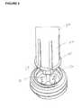
- FIG. 3is an elevational view of the tool drive portion showing resilient locking arms and a drive head portion projecting beyond the arms, and an externally threaded driven member in the form of a threaded cap locking member for a pedicle screw assembly for being rotatably driven by the drive tool;
- FIG. 4is a enlarged perspective view of the tool drive portion showing elongate slots between the resilient locking arm members, and arcuate drive lobes of the drive head portion to provide the head portion with a hexagonal configuration;
- FIG. 5is a perspective view of the tool drive portion and the threaded locking cap member showing a through bore of the locking cap member having a lower drive recess portion thereof provided with corresponding hexagonal configuration to the drive head portion of the tool;
- FIG. 5Ais an elevational view showing the threaded locking cap member releasably connected to the tool drive portion
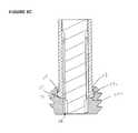
- FIG. 5Bis a sectional view showing locking end portions of the resilient locking arm members received in an elevated position in an undercut pocket in a through bore of the locking cap member;
- FIG. 5Cis a section view similar to FIG. 5B showing the locking end portions received in a lowered position in the through bore pocket;
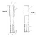
- FIG. 6is a perspective view of a sleeve member of the drive tool including the resilient arm members
- FIG. 7is an elevational view of the sleeve member of FIG. 6 showing the wedge configuration of the locking end portions of the resilient arm members;
- FIG. 8is a sectional view of the sleeve member of FIGS. 6 and 7 showing upper, inclined locking surfaces and lower, inclined cam surfaces of the locking end portions of the arm members;
- FIG. 9is a elevational view of the externally threaded locking cap member
- FIG. 10is a sectional view of the locking cap member showing the through bore including a radially smaller, lower drive recess portion and radially larger, upper securing portion thereof;
- FIG. 11is an elevational view of a pedicle screw assembly showing an outer coupling member for receiving a spinal rod extending transversely therethough, an inner securing member, and a bone screw;
- FIG. 12is an elevational view of the pedicle screw assembly of FIG. 11 showing the outer coupling member, inner securing member, and bone screw in an assembled configuration with a threaded locking cap member shown in position to be threaded into the coupling member;
- FIG. 13is a sectional view of the pedicle screw assembly of FIG. 12 showing the cooperating threads of the locking cap member and the coupling member;
- FIG. 14is an elevational view of the drive tool of FIG. 1 in position to receive the locking cap member thereon for being threaded into the coupling member of the pedicle screw assembly to lock a spinal rod therein;
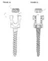
- FIG. 15is a perspective view of the drive tool of FIG. 1 having a different driven member in the form of a bone screw releasably connected thereto;
- FIG. 16is a perspective view showing the tool as a holding tool having a bone plate secured thereto;
- FIG. 17is a perspective view of an alternative drive tool and driven member releasably connected thereto.
- FIG. 18is a sectional view of the releasably connected drive tool and driven member of FIG. 17 showing locking end portions of resilient arm members of the drive tool releasably secured in an external groove of the threaded driven member.
- FIGS. 1 and 2two drive tools 10 and 12 are illustrated with the tool 10 of FIG. 1 having two identical drive portions 14 at opposite ends of the tool shaft 15 whereas tool 12 has a single drive portion 14 at its distal end 16 and is provided with a gripping handle 18 at its proximal end 20 .
- the drive portion 14is configured to both non-rotatably engage a driven member 22 such as in the form of an externally threaded locking cap device or member as shown in FIG. 3 as well as to securely hold it to the tool so as not to fall off therefrom during threading of the locking cap member 22 to, for example, pedicle screw assembly 24 (see FIGS. 11-14 ).
- the drive portion 14includes a plurality of resilient arm members 26 as well as distal drive head portion 28 .
- the resilient arm members 26are configured to securely engage and hold the locking cap member 22 to the tool shaft 15 while the drive head portion 28 transmits a rotational drive force to the locking cap member 22 as the shaft 15 is turned for threading the cap member 22 to internal threads of a surgical device, such as pedicle screw assembly 24 , as previously mentioned.
- the resilient arm members 26are each provided with a distal end locking portions 30 at their free ends, as can be seen best in FIGS. 7 and 8 .
- the distal locking portions 30are configured to cooperate with securing structure of the locking cap member 22 for securely and positively holding the cap member 22 to the tool shaft 15 , as will be described more fully hereinafter.
- the resilient arm members 26are recessed back up along tool shaft axis 32 from the bottom drive head portion 28 so that the drive head portion 28 extends down beyond the distal locking portions 30 of the resilient arm members 26 .
- the resilient arm members 26are formed by opened ended slots 34 that extend axially in sleeve member 36 at lower portion 38 thereof, as shown in FIG. 6 .
- the slots 34extend to the distal end 40 of the sleeve member 36 opening thereat so as to create separation between the resilient arm members 26 , and particularly between the distal locking portions 30 at the sleeve distal end 40 .
- the distal locking portions 30taken together form a radially enlarged lower flange portion 31 having a generally annular configuration interrupted by the slots 34 at the distal end 40 of the sleeve member 36 , as can be seen best in FIGS. 4 and 6 .
- the resiliency of the arm members 26can be controlled by varying the axial length and circumferential width of the slots 34 , as well as by varying the radial thickness of the arm members 26 and the material from which the sleeve member 36 is formed.
- the axial length of the arm members 26is approximately 0.480 inch
- the circumferential width of the slots 34is approximately 0.032 inch
- the material of the sleeve member 36is titanium or stainless steel.
- the resilient arm membersextend down along the tool shaft 15 about axis 32 thereof when the sleeve member 36 is fixedly secured to main shaft 42 as by braze welding of the proximate end 44 of the sleeve member 36 to the lower shoulder 46 of the main shaft 42 .
- the main shaft 42has a reduced lower shaft portion 48 that extends axially downwardly from the lower shoulder 46 .
- the lower shaft portion 48extends in through bore 49 of the sleeve member 36 when fixedly connected to the main shaft 42 and beyond the locking portions 30 at the end 40 thereof to the drive head portion 28 of the lower shaft portion 48 .
- the resilient arm members 26are disposed about the lower shaft portion 48 and secure the locking cap member 22 to the shaft 15 generally above and about the drive area where drive head portion 28 engages in the locking cap member 22 .
- the illustrated locking cap member 22is in the form of a threaded nut such as of titanium material and has external threads 50 and a through bore 52 , as shown in FIGS. 5 , 9 and 10 .
- the cap member 22can be non-threaded and be configured to cooperate with, for example, a non-threaded component of the pedicle screw assembly 24 for being secured thereto.
- the through bore 52has a radially larger upper, securing portion 54 including internal surfaces for cooperating with the resilient arm members 26 , and a radially smaller, lower drive recess portion 56 including inner surfaces for cooperating with the drive head portion 28 . As can be seen in FIG.
- the interior surfaces of the through bore upper portion 54have a generally annular configuration, while the interior surface of the through bore lower portion 56 can have a lobed, hexagonal configuration so as to receive the correspondingly configured drive head portion 28 in a mating fit therein.
- the diameter across generally diametrically opposite locking portions 30can be approximately 0.270 inch, and the largest diameter across the drive head portion 28 , such as across generally diametrically opposite lobe projections, can be approximately 0.180 inch.
- the effective diameter across the locking portions 30 of flange 31is 50% larger than the largest effective diameter of the drive head portion 28 .
- the largest effective diameter of the lobed drive head portion 28is the distance across the radially outwardmost points of opposite lobes of the drive head portion 28 .
- the drive head portion 28 and cooperating drive recess portion 56are configured to have a non-rotatable mating fit with each other so that each has a corresponding cross-sectional shape that is other than circular, e.g., the lobed, hexagonal configuration shape described above.
- the drive head portion 28 and the drive recess portion 56despite having a smaller diameter than the locking flange portion 31 , provide a driving area of engagement between their mating surfaces that is great enough to enable a surgeon to readily and securely apply sufficient torque to the cap member 22 for rotatably driving it to be secured to the pedicle screw assembly 24 .
- surfaces of the distal locking portions 30are provided that are inclined relative to the shaft axis 32 for cooperating with surfaces of the through bore upper securing portion 54 that are inclined with respect to the axis 58 of the locking cap member 22 .
- the locking portions 30each have an upper, inclined locking surface 60 that tapers away from the central, longitudinal shaft axis 32 as the surface 60 extends downwardly.
- the locking portions 30each further include a lower inclined cam surface 62 that has a reverse incline relative to the upper locking surface 60 so that it tapers back toward the shaft axis 32 as the surface 62 extends downwardly to the end 40 of the sleeve member 36 .
- Extending between the radially outer ends of the surfaces 60 and 62is an axially extending intermediate surface 64 such that the surfaces 60 - 64 provide each of the locking portions 30 with a generally wedged shaped configuration.
- the annular interior surfaces of the through bore portion 54 of the locking cap member 22include an upper, lead-in guide surface 66 that is inclined relative to the axis 58 so as to taper inwardly as it extends downwardly in the through bore 52 from a larger diameter at its upper end to a smaller diameter at its lower end.
- the through bore 52further includes a lower locking surface 68 that is undercut so that it has a reverse incline relative to the upper guide surface 66 to taper from its smaller diameter upper end down to a larger diameter lower end at an incline from axis 58 .
- Intermediate, axially extending surface 70interconnects the lower end of the upper guide surface 66 and the upper end of the lower locking surface 68 .
- the through bore upper portion 54has a bottom surface 71 , and the drive recess lower portion 56 is formed centrally in the bottom surface 71 to extend downwardly therefrom.
- the drive head portion 28is advanced into the through bore 52 bringing the lower cam surface 62 of the shaft 15 into engagement with the upper guide surface 66 of the locking cap member 22 .
- the resilient arm members 26Continuing to advance the drive head portion 28 axially into the bore 52 causes the resilient arm members 26 to be deflected radially inwardly due to the camming action between the engaged inclined surfaces 62 and 66 , until the upper end of the cam surface 62 clears the lower end of the guide surface 66 .
- continued insertion of the drive head portion 28causes the corresponding axially extending intermediate surfaces 64 and 70 to engage each other until the upper end of the surface 64 clears the lower end of the surface 70 .
- the resilient arm memberswill shift radially outward by resiliently snapping back toward their undeformed configuration so that the upper locking surface 60 is tightly and resiliently engaged with the lower locking surface 68 of the locking cap member 22 , and the intermediate surface 64 is tightly and resiliently engaged with axially extending annular surface 54 a extending about bore upper portion 54 and extending axially between the lower end of the lower locking surface 68 and the radially outer end of the bottom surface 71 .
- the snap-fit of the resilient locking portions 30 in the bore upper portion 54provides the surgeon tactile and audible feedback to indicated that the cap member 22 is releasably locked to the tool 10 .
- the drive head portion 28With the lobe projections 72 of the drive head portion 28 aligned with the corresponding lobe recesses 74 of the lower drive recess portion 56 of the locking cap member through bore 52 , the drive head portion 28 can be received with a mating fit in the correspondingly configured lower drive recess portion 56 with the locking surfaces 60 and 68 fully engaged with each other.
- the arm locking portions 30are fully received in an undercut pocket 73 between the inclined locking surface 68 and the bottom surface 71 of the bore upper portion 54 with the locking surfaces 60 and intermediate surfaces 64 of the resilient arm members 26 tightly engaged against the respective locking surface 68 and annular surface 54 a of the locking cap member through bore 52 due to the resilient configuration of the arm members 26 .
- the surfaces 60 and 64will be resiliently biased into tight engagement with the respective surfaces 68 and 54 a to provide a secure connection between the tool shaft 15 and the locking cap member 22 above and generally around the non-rotatable, driving engagement between the mating drive head portion 28 and the lower drive recess portion 56 of the cap member through bore 52 , as shown in FIG. 5B .
- FIG. 5Cshows the locking projections 30 fully bottomed out in the through bore upper portion 54 so that bottom surfaces 30 a of the locking projections 30 are engaged against the bottom surface 71 of the bore upper portion 54 with the surfaces 60 and 68 separated from each other.
- the surfaces 64 and 54 aare still tightly and resiliently engaged with each other due to the resilient nature of the arm members 24 as discussed above, and the cap member 22 cannot fall off the tool shaft 15 since the locking surfaces 60 and 68 remain in axial interference with one another.
- the drive head portion 28 and specifically the lobe projections 72 thereofextend axially beyond the bottom surfaces 30 a of the arm locking projections 30 by a predetermined distance that generally corresponds with the axial length of the drive recess portion 58 and specifically the lobe recesses 74 thereof.
- the lobe projections 72will be in mating relation with the corresponding lobe recesses 74 for substantially the full axial extent of one another, as shown in FIG. 5C .
- a separation forcemust be applied between the tool shaft 15 and cap member 22 as by pulling them apart from each other to cause the engaged, inclined locking surfaces 60 and 68 to cam against each other for deflecting the resilient arm members 26 sufficiently radially inward to allow them to be pulled out of the bore 52 . This can be done after the locking cap member 22 is threaded to the pedicle screw assembly 24 , or by the surgeon prior thereto if desired.
- the pressure required to both connect and disconnect the tool 10 and the cap member 22can be identical.
- the pressure required to both connect and disconnect the tool 10 and the cap member 22has been found to be approximately 3 lbs.
- thisallows the surgeon to know how much pressure they will need to use for both connecting the cap member 22 to the tool 10 and for disconnecting it from the tool 10 .
- the angles of the inclined surfacescould be made different from each other to require greater or less pressure to connect the cap member 22 to the tool 10 as compared to disconnecting it therefrom.
- the tool 10 hereinprovides a durable and robust lock with the cap member 22 as testing has shown a loss of less than 8 percent of the holding power over 5200 repetitions of connecting and disconnecting the cap member 22 to and from the tool 10 .
- Thisis reflective of the lack of wear of the tool 10 over repeated uses, and particularly of the surfaces 60 - 64 of the resilient locking portions 30 which stands in stark contrast to prior surgical drive tools that employ a taper-type lock with the driven member which are prone to a much higher wear rate and thus a much shorter functioning life span.
- the tool 10has a pair of drive portions 14 at either end thereof whereas the tool 12 only has the drive portion 14 at the distal end 16 thereof.
- the tool 10provides the surgeon with the option of loading two locking cap members 22 onto the tool shaft 15 which may be beneficial where a spinal rod 76 extends through multiple pedicle screw assemblies 24 that need to be locked down with corresponding multiple locking cap members 22 .
- the shaftis provided with an intermediate gripping portion 78 for the surgeon to turn the shaft 15 for threading the locking cap members 22 securely held onto the drive portions 14 at either end thereof into the pedicle screw assemblies 24 .
- the gripping portion 78can be enlarged relative to the remainder of the shaft 15 and be provided with gripping features, such as axially extending knurled or raised rib portions 80 or the like to allow for enhanced gripping on the shaft gripping portion 78 .
- the tool 12 of FIG. 2has a gripping handle 18 at the proximal end 20 of the shaft 15 to provide an area for the surgeon to grip for turning the shaft 15 with the locking cap member 22 secured thereto to thread it to the pedicle screw assembly 24 .
- the handle 18includes an enlarged knob end 82 and an elongate gripping surface 84 below the knob end 82 that tapers outwardly at the bottom thereof to provide an area for the handle 18 to be gripped by the surgeon.
- the illustrated pedicle screw assembly 24has an outer coupling member 86 having diametrically opposite upwardly opening slots to allow the spinal rod 76 to extend transversely therethrough.
- the pedicle screw assembly 24further includes an inner locking sleeve member 90 for locking the multi-axial bone screw 92 in a specific angular orientation relative to the coupling member 86 .
- the inner locking member 90has resilient locking arms 94 that are tightly clamped onto the bone screw head 96 as the locking sleeve 90 is advanced downwardly in the outer coupling member 86 , or alternatively or additionally as the outer coupling member 86 is drawn upwardly relative to the inner locking sleeve 90 .
- the outer coupling member 86has upper interior threads 98 that are configured to threadingly engage the external threads 54 of the locking cap 22 for locking the spinal rod 76 in the pedicle screw assembly 24 .
- pedicle screw assembliescan be utilized with a threaded member similar to locking cap member 22 that is threaded to the pedicle screw assembly with the driver tools disclosed herein.
- the driver tools described hereincan be used advantageously for holding and/or driving other implant members for different types of surgical devices such as for holding the illustrated bone plate 100 of FIG. 16 .
- the driver tool 12can be utilized to drive a threaded bone screw 101 ( FIG. 15 ) or retainer therefor releasably connected thereto through the bores 102 of the bone plate 100 for the bone screws 101 and into the underlying bone.
- the bone screw boreis configured similar to the bore of locking cap member 22 for receiving the drive portion of the drive tool therein.
- the bone plate bores 102are configured similar to the bore of the locking cap member 22 , but the head portion of the holding tool 12 and the portion of the bore in which the head portion is received need not be configured to have an engaged driving relation.
- the driver tool 12 hereinis especially useful for driving relatively small driven members that require an applied driven torque and which are used in surgical procedures, such as a crimping member for a crimping device for surgical cables.
- driver tool 12 ′can be provided to have resilient arm members 26 ′ with slots 34 ′ therebetween and a drive head portion (not shown) similar to corresponding resilient arm members 26 and drive head portion 28 of the driver tool 12 .
- the resilient arm members 26 ′have distal locking portion 30 ′ that taken together from a radially enlarged lower flange portion similar to previously described flange portion 31 ; however, the wedge-shaped locking portions 30 ′ project radially inward from the bottom of the arm members 26 ′ so that the flange portion formed thereby is enlarged in a radial inward direction rather than radial outward direction.
- the locking cap member 22 ′ shown in the form of a threaded nutalso has external threads 50 ′ and through bore 52 ′. However, the nut 22 ′ has an upper annular groove 53 ′ formed in its outer surface above the threads 50 ′.
- the locking portions 30 ′ and groove 53 ′have cooperating surfaces to provide a snap-fit therebetween with the surfaces of locking portions 30 ′ configured similar to surfaces 60 - 64 of the locking portions 30 and the groove 53 ′ having surfaces similar to at least surfaces 54 a and 68 of the undercut pocket 73 of bore portion 54 .
- the cooperating surfacesinclude inclined cam surfaces that cause the resilient arm members 26 ′ to resiliently deflect radially outward as the locking nut 22 ′ is being connected thereto with the arm members 26 ′ snapping back radially inwardly so that the locking portions 30 ′ thereof are received in the groove 53 ′.
- the reverse operationis employed to cam the locking portions 30 ′ out of the groove 53 ′.
- the through bore 52 ′need not be provided with differently configured upper and lower portions thereof similar to upper and lower portions 54 and 56 of through bore 52 . Instead, the entire through bore 52 ′ can be matched to the lower drive head portion such as by having lobe recesses 74 ′ extending for the full axial extent thereof with the lobed drive head portion provided with an axial length similar to that of the through bore 52 ′.
Landscapes
- Health & Medical Sciences (AREA)
- Orthopedic Medicine & Surgery (AREA)
- Life Sciences & Earth Sciences (AREA)
- Surgery (AREA)
- Neurology (AREA)
- Heart & Thoracic Surgery (AREA)
- Engineering & Computer Science (AREA)
- Biomedical Technology (AREA)
- Nuclear Medicine, Radiotherapy & Molecular Imaging (AREA)
- Medical Informatics (AREA)
- Molecular Biology (AREA)
- Animal Behavior & Ethology (AREA)
- General Health & Medical Sciences (AREA)
- Public Health (AREA)
- Veterinary Medicine (AREA)
- Surgical Instruments (AREA)
Abstract
Description
Claims (17)
Priority Applications (1)
| Application Number | Priority Date | Filing Date | Title |
|---|---|---|---|
| US13/272,931US8808307B2 (en) | 2010-10-13 | 2011-10-13 | Driver for a surgical device |
Applications Claiming Priority (2)
| Application Number | Priority Date | Filing Date | Title |
|---|---|---|---|
| US39282910P | 2010-10-13 | 2010-10-13 | |
| US13/272,931US8808307B2 (en) | 2010-10-13 | 2011-10-13 | Driver for a surgical device |
Publications (2)
| Publication Number | Publication Date |
|---|---|
| US20120123431A1 US20120123431A1 (en) | 2012-05-17 |
| US8808307B2true US8808307B2 (en) | 2014-08-19 |
Family
ID=46048484
Family Applications (1)
| Application Number | Title | Priority Date | Filing Date |
|---|---|---|---|
| US13/272,931ActiveUS8808307B2 (en) | 2010-10-13 | 2011-10-13 | Driver for a surgical device |
Country Status (1)
| Country | Link |
|---|---|
| US (1) | US8808307B2 (en) |
Cited By (13)
| Publication number | Priority date | Publication date | Assignee | Title |
|---|---|---|---|---|
| US20130282019A1 (en)* | 2012-04-23 | 2013-10-24 | Alphatec Spine, Inc. | Surgical Screwdriver |
| WO2016184311A1 (en)* | 2015-05-19 | 2016-11-24 | 山东威高骨科材料股份有限公司 | High-strength self-contained locking screw driver |
| US20170303981A1 (en)* | 2016-04-21 | 2017-10-26 | Symmetry Medical Manufacturing, Inc. | Self-retaining screwdriver tip and mating drive feature |
| US20200138488A1 (en)* | 2018-11-01 | 2020-05-07 | DePuy Synthes Products, Inc. | Methods, devices, and systems related to a surgical driver |
| CN113133822A (en)* | 2020-01-17 | 2021-07-20 | 华沙整形外科股份有限公司 | Variable thickness handle driver instrument |
| US20210236185A1 (en)* | 2020-02-05 | 2021-08-05 | Adam Isaac Lewis | Bone fastener and driver with retaining features |
| US11123117B1 (en) | 2011-11-01 | 2021-09-21 | Nuvasive, Inc. | Surgical fixation system and related methods |
| US11517450B2 (en) | 2019-06-27 | 2022-12-06 | Pioneer Surgical Technology, Inc. | Intervertebral implant inserter tool |
| US11540867B2 (en) | 2019-08-13 | 2023-01-03 | Pioneer Surgical Technology, Inc. | Driver for a bone screw |
| US20230346445A1 (en)* | 2022-05-01 | 2023-11-02 | Arizona Board Of Regents On Behalf Of The University Of Arizona | Cannulated bone screw extraction device and methods of use thereof |
| EP4120937A4 (en)* | 2020-03-17 | 2024-04-24 | Warsaw Orthopedic, Inc. | Set screw reducer for modular reduction screws |
| US12102348B2 (en) | 2016-09-07 | 2024-10-01 | Vertos Medical, Inc. | Percutaneous lateral recess resection methods and instruments |
| US12324572B2 (en) | 2022-06-16 | 2025-06-10 | Vertos Medical, Inc. | Integrated instrument assembly |
Families Citing this family (18)
| Publication number | Priority date | Publication date | Assignee | Title |
|---|---|---|---|---|
| US8439922B1 (en) | 2008-02-06 | 2013-05-14 | NiVasive, Inc. | Systems and methods for holding and implanting bone anchors |
| US9198698B1 (en) | 2011-02-10 | 2015-12-01 | Nuvasive, Inc. | Minimally invasive spinal fixation system and related methods |
| US9247964B1 (en)* | 2011-03-01 | 2016-02-02 | Nuasive, Inc. | Spinal Cross-connector |
| US20130325073A1 (en)* | 2012-04-23 | 2013-12-05 | George Sikora | Bone Anchors, Kits, and Methods for Securing Portions of Bone |
| US20140066945A1 (en)* | 2012-08-31 | 2014-03-06 | Warsaw Orthopedic, Inc. | Surgical implant system and method |
| US9486256B1 (en) | 2013-03-15 | 2016-11-08 | Nuvasive, Inc. | Rod reduction assemblies and related methods |
| US9526553B2 (en)* | 2014-04-04 | 2016-12-27 | K2M, Inc. | Screw insertion instrument |
| US9974577B1 (en) | 2015-05-21 | 2018-05-22 | Nuvasive, Inc. | Methods and instruments for performing leveraged reduction during single position spine surgery |
| US20170348029A1 (en)* | 2016-06-01 | 2017-12-07 | Spinecraft, LLC | RCDF Instrument, Apparatus and Procedures |
| US10709460B2 (en)* | 2016-08-01 | 2020-07-14 | Howmedica Osteonics Corp. | Centering guide system for arthroplasty |
| US10398481B2 (en) | 2016-10-03 | 2019-09-03 | Nuvasive, Inc. | Spinal fixation system |
| US10463404B2 (en) | 2017-07-27 | 2019-11-05 | Warsaw Orthopedic, Inc. | Spinal implant system and method |
| US11051861B2 (en) | 2018-06-13 | 2021-07-06 | Nuvasive, Inc. | Rod reduction assemblies and related methods |
| US11311314B2 (en)* | 2018-07-31 | 2022-04-26 | GetSet Surgical SA | Spinal surgery systems and methods |
| US11020154B2 (en)* | 2019-04-26 | 2021-06-01 | Warsaw Orthopedic, Inc. | Surgical instrument and methods of use |
| US11589902B2 (en)* | 2019-12-09 | 2023-02-28 | Globus Medical Inc. | Pol y axial screw and locking cap |
| EP3838197B1 (en)* | 2019-12-18 | 2024-03-13 | Biedermann Technologies GmbH & Co. KG | Instrument for use with a bone anchoring device |
| WO2022096753A1 (en)* | 2020-11-09 | 2022-05-12 | Medos International Sarl | Multiple set screw insertion instrument and methods |
Citations (32)
| Publication number | Priority date | Publication date | Assignee | Title |
|---|---|---|---|---|
| US2317319A (en) | 1941-11-14 | 1943-04-20 | Champion Inc | Screw driver |
| US2404427A (en) | 1944-02-23 | 1946-07-23 | Bloomfield Samuel | Expansible jaw screw driver |
| US2634641A (en) | 1950-02-20 | 1953-04-14 | Charles L Hodges | Fastener-holding socket wrench |
| US2737988A (en) | 1952-03-26 | 1956-03-13 | Roy E Gearhart | Screw holding attachment for screwdrivers |
| US3150698A (en) | 1960-09-08 | 1964-09-29 | H J J Company | Screw-holding screw driver |
| US3409058A (en) | 1966-10-19 | 1968-11-05 | Parker Mfg Company | Screw holder and driver |
| US4552044A (en) | 1985-02-12 | 1985-11-12 | Antonio Corona | Multibit screwdriver with improved bit insertion |
| US4813808A (en) | 1983-08-19 | 1989-03-21 | Gkn Automotive Components Inc. | Axial retaining member and method for interconnecting male and female splined members |
| US4924736A (en) | 1989-05-04 | 1990-05-15 | A.T. & G Company, Inc. | Gripping screw drive bit |
| US5007666A (en) | 1990-01-19 | 1991-04-16 | C & L Development Inc. | Tongue and groove snap-fit pipe coupling |
| US5025688A (en) | 1990-05-22 | 1991-06-25 | Ryder International Corp. | Expandable drive tool tip for screw retention |
| US5782918A (en) | 1996-12-12 | 1998-07-21 | Folsom Metal Products | Implant abutment system |
| US6220122B1 (en) | 1999-10-20 | 2001-04-24 | Illinois Tool Works Inc | Fastener holding tool and system |
| US6361535B2 (en) | 2000-02-16 | 2002-03-26 | Roger P. Jackson | Bone screw threaded plug closure with central set screw |
| US6382977B1 (en) | 2000-03-02 | 2002-05-07 | Nobel Biocare Usa, Inc. | Snap-in impression coping |
| US6497166B1 (en) | 2000-11-07 | 2002-12-24 | Mark Fleckenstein | Screw setter tool |
| US6726689B2 (en) | 2002-09-06 | 2004-04-27 | Roger P. Jackson | Helical interlocking mating guide and advancement structure |
| US6786903B2 (en) | 2002-01-24 | 2004-09-07 | A-Spine Holding Group Corp. | Rotary device for fixing spinal column under treatment |
| US6904836B1 (en) | 2002-02-01 | 2005-06-14 | Petru Andrei | Screw holding screwdriver adapter |
| US20050216015A1 (en) | 2004-03-27 | 2005-09-29 | Winfried Kreidler | System with a screwdriver and a bone screw |
| US20070093831A1 (en) | 2004-02-27 | 2007-04-26 | Abdelgany Mahmoud F | Biased angle polyaxial pedicle screw assembly |
| US7249544B2 (en) | 2002-04-18 | 2007-07-31 | Katsuyuki Totsu | Screw holding type screwdriver bit and combination thereof with screws |
| US20080045955A1 (en)* | 2006-08-16 | 2008-02-21 | Berrevoets Gregory A | Spinal Rod Anchor Device and Method |
| US7338286B2 (en) | 2002-11-13 | 2008-03-04 | Biomet 3I, Inc. | Dental implant system |
| US20080154277A1 (en)* | 2004-10-26 | 2008-06-26 | Scott Machalk | Tool apparatus for locking a spinal rod in an anchoring device therefor |
| US7757590B2 (en) | 2006-06-23 | 2010-07-20 | Darian Swartz | Fastener holding device |
| US20100222827A1 (en) | 2009-02-10 | 2010-09-02 | Bryan Griffiths | Screw with variable diameter cannulation and driver |
| US7862588B2 (en) | 2005-02-18 | 2011-01-04 | Samy Abdou | Devices and methods for dynamic fixation of skeletal structure |
| US7909834B2 (en) | 2004-12-15 | 2011-03-22 | Depuy Spine, Inc. | Self retaining set screw inserter |
| US8002806B2 (en) | 2005-10-20 | 2011-08-23 | Warsaw Orthopedic, Inc. | Bottom loading multi-axial screw assembly |
| US20120253397A1 (en) | 2009-12-10 | 2012-10-04 | Kilian Kraus | Rod connector |
| US8298274B2 (en) | 1999-09-01 | 2012-10-30 | Warsaw Orthopedic, Inc. | Multi-axial bone screw assembly |
- 2011
- 2011-10-13USUS13/272,931patent/US8808307B2/enactiveActive
Patent Citations (32)
| Publication number | Priority date | Publication date | Assignee | Title |
|---|---|---|---|---|
| US2317319A (en) | 1941-11-14 | 1943-04-20 | Champion Inc | Screw driver |
| US2404427A (en) | 1944-02-23 | 1946-07-23 | Bloomfield Samuel | Expansible jaw screw driver |
| US2634641A (en) | 1950-02-20 | 1953-04-14 | Charles L Hodges | Fastener-holding socket wrench |
| US2737988A (en) | 1952-03-26 | 1956-03-13 | Roy E Gearhart | Screw holding attachment for screwdrivers |
| US3150698A (en) | 1960-09-08 | 1964-09-29 | H J J Company | Screw-holding screw driver |
| US3409058A (en) | 1966-10-19 | 1968-11-05 | Parker Mfg Company | Screw holder and driver |
| US4813808A (en) | 1983-08-19 | 1989-03-21 | Gkn Automotive Components Inc. | Axial retaining member and method for interconnecting male and female splined members |
| US4552044A (en) | 1985-02-12 | 1985-11-12 | Antonio Corona | Multibit screwdriver with improved bit insertion |
| US4924736A (en) | 1989-05-04 | 1990-05-15 | A.T. & G Company, Inc. | Gripping screw drive bit |
| US5007666A (en) | 1990-01-19 | 1991-04-16 | C & L Development Inc. | Tongue and groove snap-fit pipe coupling |
| US5025688A (en) | 1990-05-22 | 1991-06-25 | Ryder International Corp. | Expandable drive tool tip for screw retention |
| US5782918A (en) | 1996-12-12 | 1998-07-21 | Folsom Metal Products | Implant abutment system |
| US8298274B2 (en) | 1999-09-01 | 2012-10-30 | Warsaw Orthopedic, Inc. | Multi-axial bone screw assembly |
| US6220122B1 (en) | 1999-10-20 | 2001-04-24 | Illinois Tool Works Inc | Fastener holding tool and system |
| US6361535B2 (en) | 2000-02-16 | 2002-03-26 | Roger P. Jackson | Bone screw threaded plug closure with central set screw |
| US6382977B1 (en) | 2000-03-02 | 2002-05-07 | Nobel Biocare Usa, Inc. | Snap-in impression coping |
| US6497166B1 (en) | 2000-11-07 | 2002-12-24 | Mark Fleckenstein | Screw setter tool |
| US6786903B2 (en) | 2002-01-24 | 2004-09-07 | A-Spine Holding Group Corp. | Rotary device for fixing spinal column under treatment |
| US6904836B1 (en) | 2002-02-01 | 2005-06-14 | Petru Andrei | Screw holding screwdriver adapter |
| US7249544B2 (en) | 2002-04-18 | 2007-07-31 | Katsuyuki Totsu | Screw holding type screwdriver bit and combination thereof with screws |
| US6726689B2 (en) | 2002-09-06 | 2004-04-27 | Roger P. Jackson | Helical interlocking mating guide and advancement structure |
| US7338286B2 (en) | 2002-11-13 | 2008-03-04 | Biomet 3I, Inc. | Dental implant system |
| US20070093831A1 (en) | 2004-02-27 | 2007-04-26 | Abdelgany Mahmoud F | Biased angle polyaxial pedicle screw assembly |
| US20050216015A1 (en) | 2004-03-27 | 2005-09-29 | Winfried Kreidler | System with a screwdriver and a bone screw |
| US20080154277A1 (en)* | 2004-10-26 | 2008-06-26 | Scott Machalk | Tool apparatus for locking a spinal rod in an anchoring device therefor |
| US7909834B2 (en) | 2004-12-15 | 2011-03-22 | Depuy Spine, Inc. | Self retaining set screw inserter |
| US7862588B2 (en) | 2005-02-18 | 2011-01-04 | Samy Abdou | Devices and methods for dynamic fixation of skeletal structure |
| US8002806B2 (en) | 2005-10-20 | 2011-08-23 | Warsaw Orthopedic, Inc. | Bottom loading multi-axial screw assembly |
| US7757590B2 (en) | 2006-06-23 | 2010-07-20 | Darian Swartz | Fastener holding device |
| US20080045955A1 (en)* | 2006-08-16 | 2008-02-21 | Berrevoets Gregory A | Spinal Rod Anchor Device and Method |
| US20100222827A1 (en) | 2009-02-10 | 2010-09-02 | Bryan Griffiths | Screw with variable diameter cannulation and driver |
| US20120253397A1 (en) | 2009-12-10 | 2012-10-04 | Kilian Kraus | Rod connector |
Cited By (19)
| Publication number | Priority date | Publication date | Assignee | Title |
|---|---|---|---|---|
| US11123117B1 (en) | 2011-11-01 | 2021-09-21 | Nuvasive, Inc. | Surgical fixation system and related methods |
| US8932303B2 (en)* | 2012-04-23 | 2015-01-13 | Alphatec Spine Inc | Surgical screwdriver |
| US20130282019A1 (en)* | 2012-04-23 | 2013-10-24 | Alphatec Spine, Inc. | Surgical Screwdriver |
| WO2016184311A1 (en)* | 2015-05-19 | 2016-11-24 | 山东威高骨科材料股份有限公司 | High-strength self-contained locking screw driver |
| US20170303981A1 (en)* | 2016-04-21 | 2017-10-26 | Symmetry Medical Manufacturing, Inc. | Self-retaining screwdriver tip and mating drive feature |
| US12102348B2 (en) | 2016-09-07 | 2024-10-01 | Vertos Medical, Inc. | Percutaneous lateral recess resection methods and instruments |
| US20200138488A1 (en)* | 2018-11-01 | 2020-05-07 | DePuy Synthes Products, Inc. | Methods, devices, and systems related to a surgical driver |
| US10842540B2 (en)* | 2018-11-01 | 2020-11-24 | Medos International Sarl | Methods, devices, and systems related to a surgical driver |
| US11517450B2 (en) | 2019-06-27 | 2022-12-06 | Pioneer Surgical Technology, Inc. | Intervertebral implant inserter tool |
| US11540867B2 (en) | 2019-08-13 | 2023-01-03 | Pioneer Surgical Technology, Inc. | Driver for a bone screw |
| US11547460B2 (en)* | 2020-01-17 | 2023-01-10 | Warsaw Orthopedic, Inc. | Variable-thickness-handle driver instrument |
| US20210220034A1 (en)* | 2020-01-17 | 2021-07-22 | Warsaw Orthopedic, Inc. | Variable-Thickness-Handle Driver Instrument |
| CN113133822A (en)* | 2020-01-17 | 2021-07-20 | 华沙整形外科股份有限公司 | Variable thickness handle driver instrument |
| US20210236185A1 (en)* | 2020-02-05 | 2021-08-05 | Adam Isaac Lewis | Bone fastener and driver with retaining features |
| US11707311B2 (en)* | 2020-02-05 | 2023-07-25 | Adam Isaac Lewis | Bone fastener and driver with retaining features |
| EP4120937A4 (en)* | 2020-03-17 | 2024-04-24 | Warsaw Orthopedic, Inc. | Set screw reducer for modular reduction screws |
| US20230346445A1 (en)* | 2022-05-01 | 2023-11-02 | Arizona Board Of Regents On Behalf Of The University Of Arizona | Cannulated bone screw extraction device and methods of use thereof |
| US12324572B2 (en) | 2022-06-16 | 2025-06-10 | Vertos Medical, Inc. | Integrated instrument assembly |
| US12342999B2 (en) | 2022-06-16 | 2025-07-01 | Vertos Medical, Inc. | Integrated instrument assembly |
Also Published As
| Publication number | Publication date |
|---|---|
| US20120123431A1 (en) | 2012-05-17 |
Similar Documents
| Publication | Publication Date | Title |
|---|---|---|
| US8808307B2 (en) | Driver for a surgical device | |
| US20210228201A1 (en) | Fenestrated locking suture anchor assembly | |
| US20240206925A1 (en) | Rod reducing apparatus and associated methods | |
| US10653460B2 (en) | Orthopedic implant rod reduction tool set and method | |
| US8128667B2 (en) | Anti-splay medical implant closure with multi-surface removal aperture | |
| US9956004B2 (en) | Multi-start closures for open implants | |
| EP2939621B1 (en) | Screw insertion instrument | |
| US9050139B2 (en) | Orthopedic implant rod reduction tool set and method | |
| US6884244B1 (en) | Removable medical implant closure for open headed implants | |
| US8287575B2 (en) | Polyaxial locking mechanism | |
| US20040167525A1 (en) | Anti-splay medical implant closure with multi-stepped removal counterbore | |
| US20040167524A1 (en) | Anti-splay medical implant closure with central multi-surface insertion and removal aperture | |
| WO2007018861A2 (en) | Removable medical implant closure | |
| AU2006317572A1 (en) | Reverse angled threadform with anti-splay clearance | |
| WO2005081692A2 (en) | Closure for rod receiving orthopedic implant having a pair of spaced apertures for removal | |
| US8523915B2 (en) | Friction set screw for use with spinal implant systems | |
| EP1871246A2 (en) | Removable medical implant closure | |
| KR20130047611A (en) | A locking assembly for a polyaxial bone anchoring device | |
| US12408910B2 (en) | Healicoil knotless distal tip and plug transmission | |
| JP7239970B2 (en) | bone fixation system |
Legal Events
| Date | Code | Title | Description |
|---|---|---|---|
| AS | Assignment | Owner name:PIONEER SURGICAL TECHNOLOGY, INC., MICHIGAN Free format text:ASSIGNMENT OF ASSIGNORS INTEREST;ASSIGNOR:ROBINSON, DANIEL RAE;REEL/FRAME:027420/0344 Effective date:20111205 | |
| AS | Assignment | Owner name:TD BANK, N.A., AS ADMINISTRATIVE AGENT, FLORIDA Free format text:SECURITY AGREEMENT;ASSIGNOR:PIONEER SURGICAL TECHNOLOGY, INC.;REEL/FRAME:030892/0193 Effective date:20130716 | |
| STCF | Information on status: patent grant | Free format text:PATENTED CASE | |
| MAFP | Maintenance fee payment | Free format text:PAYMENT OF MAINTENANCE FEE, 4TH YEAR, LARGE ENTITY (ORIGINAL EVENT CODE: M1551) Year of fee payment:4 | |
| AS | Assignment | Owner name:JPMORGAN CHASE BANK, N.A., AS THE ADMINISTRATIVE AGENT, ILLINOIS Free format text:SECURITY INTEREST;ASSIGNORS:RTI SURGICAL, INC.;PIONEER SURGICAL TECHNOLOGY, INC.;TUTOGEN MEDICAL, INC.;REEL/FRAME:046303/0926 Effective date:20180605 Owner name:JPMORGAN CHASE BANK, N.A., AS THE ADMINISTRATIVE A Free format text:SECURITY INTEREST;ASSIGNORS:RTI SURGICAL, INC.;PIONEER SURGICAL TECHNOLOGY, INC.;TUTOGEN MEDICAL, INC.;REEL/FRAME:046303/0926 Effective date:20180605 | |
| AS | Assignment | Owner name:PIONEER SURGICAL TECHNOLOGY, INC., FLORIDA Free format text:RELEASE BY SECURED PARTY;ASSIGNOR:TD BANK, N.A., AS ADMINISTRATIVE AGENT;REEL/FRAME:046320/0040 Effective date:20180605 | |
| AS | Assignment | Owner name:ARES CAPITAL CORPORATION, AS ADMINISTRATIVE AGENT, Free format text:SECURITY INTEREST;ASSIGNORS:RTI SURGICAL, INC.;PIONEER SURGICAL TECHNOLOGY, INC.;TUTOGEN MEDICAL, INC.;AND OTHERS;REEL/FRAME:048543/0505 Effective date:20190308 Owner name:ARES CAPITAL CORPORATION, AS ADMINISTRATIVE AGENT, NEW YORK Free format text:SECURITY INTEREST;ASSIGNORS:RTI SURGICAL, INC.;PIONEER SURGICAL TECHNOLOGY, INC.;TUTOGEN MEDICAL, INC.;AND OTHERS;REEL/FRAME:048543/0505 Effective date:20190308 | |
| AS | Assignment | Owner name:TUTOGEN MEDICAL, INC., FLORIDA Free format text:RELEASE BY SECURED PARTY;ASSIGNOR:ARES CAPITAL CORPORATION, AS AGENT;REEL/FRAME:053257/0652 Effective date:20200720 Owner name:PIONEER SURGICAL TECHNOLOGY, INC., FLORIDA Free format text:RELEASE BY SECURED PARTY;ASSIGNOR:ARES CAPITAL CORPORATION, AS AGENT;REEL/FRAME:053257/0652 Effective date:20200720 Owner name:PARADIGM SPINE, LLC, NEW YORK Free format text:RELEASE BY SECURED PARTY;ASSIGNOR:ARES CAPITAL CORPORATION, AS AGENT;REEL/FRAME:053257/0652 Effective date:20200720 Owner name:RTI SURGICAL, INC., FLORIDA Free format text:RELEASE BY SECURED PARTY;ASSIGNOR:ARES CAPITAL CORPORATION, AS AGENT;REEL/FRAME:053257/0652 Effective date:20200720 Owner name:FOURTH DIMENSION SPINE, LLC, NEW YORK Free format text:RELEASE BY SECURED PARTY;ASSIGNOR:ARES CAPITAL CORPORATION, AS AGENT;REEL/FRAME:053257/0652 Effective date:20200720 | |
| AS | Assignment | Owner name:RTI SURGICAL, INC., FLORIDA Free format text:RELEASE BY SECURED PARTY;ASSIGNOR:JPMORGAN CHASE BANK, N.A., AS ADMINISTRATIVE AGENT;REEL/FRAME:053260/0398 Effective date:20200720 Owner name:TUTOGEN MEDICAL, INC., FLORIDA Free format text:RELEASE BY SECURED PARTY;ASSIGNOR:JPMORGAN CHASE BANK, N.A., AS ADMINISTRATIVE AGENT;REEL/FRAME:053260/0398 Effective date:20200720 Owner name:PIONEER SURGICAL TECHNOLOGY, INC., FLORIDA Free format text:RELEASE BY SECURED PARTY;ASSIGNOR:JPMORGAN CHASE BANK, N.A., AS ADMINISTRATIVE AGENT;REEL/FRAME:053260/0398 Effective date:20200720 | |
| MAFP | Maintenance fee payment | Free format text:PAYMENT OF MAINTENANCE FEE, 8TH YEAR, LARGE ENTITY (ORIGINAL EVENT CODE: M1552); ENTITY STATUS OF PATENT OWNER: LARGE ENTITY Year of fee payment:8 | |
| AS | Assignment | Owner name:XTANT MEDICAL HOLDINGS, INC., MONTANA Free format text:ASSIGNMENT OF ASSIGNORS INTEREST;ASSIGNOR:PIONEER SURGICAL TECHNOLOGY NEWCO, INC.;REEL/FRAME:065218/0590 Effective date:20230810 | |
| AS | Assignment | Owner name:PIONEER SURGICAL TECHNOLOGY NEWCO, INC., TEXAS Free format text:MERGER;ASSIGNOR:PIONEER SURGICAL TECHNOLOGY, INC.;REEL/FRAME:065287/0641 Effective date:20230614 | |
| AS | Assignment | Owner name:MIDCAP FUNDING IV TRUST, MARYLAND Free format text:SECURITY AGREEMENT SUPPLEMENT (REVOLVING);ASSIGNORS:XTANT MEDICAL HOLDINGS, INC.;XTANT MEDICAL, INC.;BACTERIN INTERNATIONAL, INC.;AND OTHERS;REEL/FRAME:066095/0652 Effective date:20231218 Owner name:MIDCAP FINANCIAL TRUST, MARYLAND Free format text:SECURITY AGREEMENT SUPPLEMENT (TERM);ASSIGNORS:XTANT MEDICAL HOLDINGS, INC.;XTANT MEDICAL, INC.;BACTERIN INTERNATIONAL, INC.;AND OTHERS;REEL/FRAME:066095/0635 Effective date:20231218 | |
| AS | Assignment | Owner name:MIDCAP FINANCIAL TRUST, MARYLAND Free format text:SECURITY INTEREST;ASSIGNORS:XTANT MEDICAL, INC.;BACTERIN INTERNATIONAL, INC.;X-SPINE SYSTEMS, INC.;AND OTHERS;REEL/FRAME:068539/0665 Effective date:20240307 Owner name:MIDCAP FUNDING IV TRUST, MARYLAND Free format text:SECURITY INTEREST;ASSIGNORS:XTANT MEDICAL, INC.;BACTERIN INTERNATIONAL, INC.;X-SPINE SYSTEMS, INC.;AND OTHERS;REEL/FRAME:068539/0492 Effective date:20240307 |