US8808039B2 - Connector assembly and terminal retainer - Google Patents
Connector assembly and terminal retainerDownload PDFInfo
- Publication number
- US8808039B2 US8808039B2US13/588,542US201213588542AUS8808039B2US 8808039 B2US8808039 B2US 8808039B2US 201213588542 AUS201213588542 AUS 201213588542AUS 8808039 B2US8808039 B2US 8808039B2
- Authority
- US
- United States
- Prior art keywords
- receptacle
- retainer
- assembly
- fastener
- housing
- Prior art date
- Legal status (The legal status is an assumption and is not a legal conclusion. Google has not performed a legal analysis and makes no representation as to the accuracy of the status listed.)
- Active, expires
Links
- 238000000465mouldingMethods0.000claimsdescription6
- 239000000463materialSubstances0.000description10
- 230000000712assemblyEffects0.000description9
- 238000000429assemblyMethods0.000description9
- 238000009434installationMethods0.000description5
- 230000009286beneficial effectEffects0.000description4
- 230000014759maintenance of locationEffects0.000description4
- 230000000717retained effectEffects0.000description4
- 238000003780insertionMethods0.000description3
- 230000037431insertionEffects0.000description3
- 239000004020conductorSubstances0.000description2
- 229920001971elastomerPolymers0.000description2
- 238000004519manufacturing processMethods0.000description2
- 238000003491arrayMethods0.000description1
- 238000005452bendingMethods0.000description1
- 230000009977dual effectEffects0.000description1
- 239000000806elastomerSubstances0.000description1
- 230000036316preloadEffects0.000description1
Images


Classifications
- B—PERFORMING OPERATIONS; TRANSPORTING
- B60—VEHICLES IN GENERAL
- B60L—PROPULSION OF ELECTRICALLY-PROPELLED VEHICLES; SUPPLYING ELECTRIC POWER FOR AUXILIARY EQUIPMENT OF ELECTRICALLY-PROPELLED VEHICLES; ELECTRODYNAMIC BRAKE SYSTEMS FOR VEHICLES IN GENERAL; MAGNETIC SUSPENSION OR LEVITATION FOR VEHICLES; MONITORING OPERATING VARIABLES OF ELECTRICALLY-PROPELLED VEHICLES; ELECTRIC SAFETY DEVICES FOR ELECTRICALLY-PROPELLED VEHICLES
- B60L53/00—Methods of charging batteries, specially adapted for electric vehicles; Charging stations or on-board charging equipment therefor; Exchange of energy storage elements in electric vehicles
- B60L53/10—Methods of charging batteries, specially adapted for electric vehicles; Charging stations or on-board charging equipment therefor; Exchange of energy storage elements in electric vehicles characterised by the energy transfer between the charging station and the vehicle
- B60L53/14—Conductive energy transfer
- B60L53/16—Connectors, e.g. plugs or sockets, specially adapted for charging electric vehicles
- B—PERFORMING OPERATIONS; TRANSPORTING
- B60—VEHICLES IN GENERAL
- B60L—PROPULSION OF ELECTRICALLY-PROPELLED VEHICLES; SUPPLYING ELECTRIC POWER FOR AUXILIARY EQUIPMENT OF ELECTRICALLY-PROPELLED VEHICLES; ELECTRODYNAMIC BRAKE SYSTEMS FOR VEHICLES IN GENERAL; MAGNETIC SUSPENSION OR LEVITATION FOR VEHICLES; MONITORING OPERATING VARIABLES OF ELECTRICALLY-PROPELLED VEHICLES; ELECTRIC SAFETY DEVICES FOR ELECTRICALLY-PROPELLED VEHICLES
- B60L53/00—Methods of charging batteries, specially adapted for electric vehicles; Charging stations or on-board charging equipment therefor; Exchange of energy storage elements in electric vehicles
- B60L53/30—Constructional details of charging stations
- B60L53/31—Charging columns specially adapted for electric vehicles
- B—PERFORMING OPERATIONS; TRANSPORTING
- B60—VEHICLES IN GENERAL
- B60R—VEHICLES, VEHICLE FITTINGS, OR VEHICLE PARTS, NOT OTHERWISE PROVIDED FOR
- B60R16/00—Electric or fluid circuits specially adapted for vehicles and not otherwise provided for; Arrangement of elements of electric or fluid circuits specially adapted for vehicles and not otherwise provided for
- B60R16/02—Electric or fluid circuits specially adapted for vehicles and not otherwise provided for; Arrangement of elements of electric or fluid circuits specially adapted for vehicles and not otherwise provided for electric constitutive elements
- B60R16/03—Electric or fluid circuits specially adapted for vehicles and not otherwise provided for; Arrangement of elements of electric or fluid circuits specially adapted for vehicles and not otherwise provided for electric constitutive elements for supply of electrical power to vehicle subsystems or for
- H—ELECTRICITY
- H01—ELECTRIC ELEMENTS
- H01R—ELECTRICALLY-CONDUCTIVE CONNECTIONS; STRUCTURAL ASSOCIATIONS OF A PLURALITY OF MUTUALLY-INSULATED ELECTRICAL CONNECTING ELEMENTS; COUPLING DEVICES; CURRENT COLLECTORS
- H01R13/00—Details of coupling devices of the kinds covered by groups H01R12/70 or H01R24/00 - H01R33/00
- H01R13/40—Securing contact members in or to a base or case; Insulating of contact members
- H01R13/42—Securing in a demountable manner
- H01R13/426—Securing by a separate resilient retaining piece supported by base or case, e.g. collar or metal contact-retention clip
- H—ELECTRICITY
- H01—ELECTRIC ELEMENTS
- H01R—ELECTRICALLY-CONDUCTIVE CONNECTIONS; STRUCTURAL ASSOCIATIONS OF A PLURALITY OF MUTUALLY-INSULATED ELECTRICAL CONNECTING ELEMENTS; COUPLING DEVICES; CURRENT COLLECTORS
- H01R13/00—Details of coupling devices of the kinds covered by groups H01R12/70 or H01R24/00 - H01R33/00
- H01R13/46—Bases; Cases
- H01R13/502—Bases; Cases composed of different pieces
- H—ELECTRICITY
- H01—ELECTRIC ELEMENTS
- H01R—ELECTRICALLY-CONDUCTIVE CONNECTIONS; STRUCTURAL ASSOCIATIONS OF A PLURALITY OF MUTUALLY-INSULATED ELECTRICAL CONNECTING ELEMENTS; COUPLING DEVICES; CURRENT COLLECTORS
- H01R13/00—Details of coupling devices of the kinds covered by groups H01R12/70 or H01R24/00 - H01R33/00
- H01R13/62—Means for facilitating engagement or disengagement of coupling parts or for holding them in engagement
- H01R13/627—Snap or like fastening
- H01R13/6275—Latching arms not integral with the housing
- H—ELECTRICITY
- H01—ELECTRIC ELEMENTS
- H01R—ELECTRICALLY-CONDUCTIVE CONNECTIONS; STRUCTURAL ASSOCIATIONS OF A PLURALITY OF MUTUALLY-INSULATED ELECTRICAL CONNECTING ELEMENTS; COUPLING DEVICES; CURRENT COLLECTORS
- H01R13/00—Details of coupling devices of the kinds covered by groups H01R12/70 or H01R24/00 - H01R33/00
- H01R13/62—Means for facilitating engagement or disengagement of coupling parts or for holding them in engagement
- H01R13/629—Additional means for facilitating engagement or disengagement of coupling parts, e.g. aligning or guiding means, levers, gas pressure electrical locking indicators, manufacturing tolerances
- B—PERFORMING OPERATIONS; TRANSPORTING
- B60—VEHICLES IN GENERAL
- B60L—PROPULSION OF ELECTRICALLY-PROPELLED VEHICLES; SUPPLYING ELECTRIC POWER FOR AUXILIARY EQUIPMENT OF ELECTRICALLY-PROPELLED VEHICLES; ELECTRODYNAMIC BRAKE SYSTEMS FOR VEHICLES IN GENERAL; MAGNETIC SUSPENSION OR LEVITATION FOR VEHICLES; MONITORING OPERATING VARIABLES OF ELECTRICALLY-PROPELLED VEHICLES; ELECTRIC SAFETY DEVICES FOR ELECTRICALLY-PROPELLED VEHICLES
- B60L2270/00—Problem solutions or means not otherwise provided for
- B60L2270/30—Preventing theft during charging
- B60L2270/32—Preventing theft during charging of electricity
- B—PERFORMING OPERATIONS; TRANSPORTING
- B60—VEHICLES IN GENERAL
- B60L—PROPULSION OF ELECTRICALLY-PROPELLED VEHICLES; SUPPLYING ELECTRIC POWER FOR AUXILIARY EQUIPMENT OF ELECTRICALLY-PROPELLED VEHICLES; ELECTRODYNAMIC BRAKE SYSTEMS FOR VEHICLES IN GENERAL; MAGNETIC SUSPENSION OR LEVITATION FOR VEHICLES; MONITORING OPERATING VARIABLES OF ELECTRICALLY-PROPELLED VEHICLES; ELECTRIC SAFETY DEVICES FOR ELECTRICALLY-PROPELLED VEHICLES
- B60L2270/00—Problem solutions or means not otherwise provided for
- B60L2270/30—Preventing theft during charging
- B60L2270/34—Preventing theft during charging of parts
- H—ELECTRICITY
- H01—ELECTRIC ELEMENTS
- H01R—ELECTRICALLY-CONDUCTIVE CONNECTIONS; STRUCTURAL ASSOCIATIONS OF A PLURALITY OF MUTUALLY-INSULATED ELECTRICAL CONNECTING ELEMENTS; COUPLING DEVICES; CURRENT COLLECTORS
- H01R13/00—Details of coupling devices of the kinds covered by groups H01R12/70 or H01R24/00 - H01R33/00
- H01R13/02—Contact members
- H01R13/15—Pins, blades or sockets having separate spring member for producing or increasing contact pressure
- H01R13/187—Pins, blades or sockets having separate spring member for producing or increasing contact pressure with spring member in the socket
- Y—GENERAL TAGGING OF NEW TECHNOLOGICAL DEVELOPMENTS; GENERAL TAGGING OF CROSS-SECTIONAL TECHNOLOGIES SPANNING OVER SEVERAL SECTIONS OF THE IPC; TECHNICAL SUBJECTS COVERED BY FORMER USPC CROSS-REFERENCE ART COLLECTIONS [XRACs] AND DIGESTS
- Y02—TECHNOLOGIES OR APPLICATIONS FOR MITIGATION OR ADAPTATION AGAINST CLIMATE CHANGE
- Y02T—CLIMATE CHANGE MITIGATION TECHNOLOGIES RELATED TO TRANSPORTATION
- Y02T10/00—Road transport of goods or passengers
- Y02T10/60—Other road transportation technologies with climate change mitigation effect
- Y02T10/70—Energy storage systems for electromobility, e.g. batteries
- Y—GENERAL TAGGING OF NEW TECHNOLOGICAL DEVELOPMENTS; GENERAL TAGGING OF CROSS-SECTIONAL TECHNOLOGIES SPANNING OVER SEVERAL SECTIONS OF THE IPC; TECHNICAL SUBJECTS COVERED BY FORMER USPC CROSS-REFERENCE ART COLLECTIONS [XRACs] AND DIGESTS
- Y02—TECHNOLOGIES OR APPLICATIONS FOR MITIGATION OR ADAPTATION AGAINST CLIMATE CHANGE
- Y02T—CLIMATE CHANGE MITIGATION TECHNOLOGIES RELATED TO TRANSPORTATION
- Y02T10/00—Road transport of goods or passengers
- Y02T10/60—Other road transportation technologies with climate change mitigation effect
- Y02T10/7072—Electromobility specific charging systems or methods for batteries, ultracapacitors, supercapacitors or double-layer capacitors
- Y—GENERAL TAGGING OF NEW TECHNOLOGICAL DEVELOPMENTS; GENERAL TAGGING OF CROSS-SECTIONAL TECHNOLOGIES SPANNING OVER SEVERAL SECTIONS OF THE IPC; TECHNICAL SUBJECTS COVERED BY FORMER USPC CROSS-REFERENCE ART COLLECTIONS [XRACs] AND DIGESTS
- Y02—TECHNOLOGIES OR APPLICATIONS FOR MITIGATION OR ADAPTATION AGAINST CLIMATE CHANGE
- Y02T—CLIMATE CHANGE MITIGATION TECHNOLOGIES RELATED TO TRANSPORTATION
- Y02T90/00—Enabling technologies or technologies with a potential or indirect contribution to GHG emissions mitigation
- Y02T90/10—Technologies relating to charging of electric vehicles
- Y02T90/12—Electric charging stations
- Y—GENERAL TAGGING OF NEW TECHNOLOGICAL DEVELOPMENTS; GENERAL TAGGING OF CROSS-SECTIONAL TECHNOLOGIES SPANNING OVER SEVERAL SECTIONS OF THE IPC; TECHNICAL SUBJECTS COVERED BY FORMER USPC CROSS-REFERENCE ART COLLECTIONS [XRACs] AND DIGESTS
- Y02—TECHNOLOGIES OR APPLICATIONS FOR MITIGATION OR ADAPTATION AGAINST CLIMATE CHANGE
- Y02T—CLIMATE CHANGE MITIGATION TECHNOLOGIES RELATED TO TRANSPORTATION
- Y02T90/00—Enabling technologies or technologies with a potential or indirect contribution to GHG emissions mitigation
- Y02T90/10—Technologies relating to charging of electric vehicles
- Y02T90/14—Plug-in electric vehicles
Definitions
- Various embodimentsrelate to electrical receptacle assemblies and retainers for receptacle assemblies.
- a receptacle assemblyis provided with a longitudinal housing with at least one receptacle formed therein with an opening at a distal end of the housing.
- An electrically conductive terminalis received within the receptacle.
- a longitudinal guide bodyis received within the receptacle in engagement with the terminal.
- the guide bodyhas an aperture formed therethrough, which is sized to receive a pin through the aperture.
- At least one fastenerextends from the guide body to provide an interference fit with the housing.
- a retaineris provided to retain an electrically conductive terminal within a receptacle.
- the retainerhas a longitudinal guide body sized to be received within the receptacle and engage the terminal to retain the terminal within the receptacle.
- the guide bodyhas an aperture formed therethrough, which is sized to receive a pin through the aperture to contact the terminal.
- At least one fastenerextends from the guide body to fasten the retainer to the receptacle.
- a receptacle assemblyis provided with a longitudinal housing with at least one receptacle formed therein with an opening at a distal end of the housing and a groove formed in the housing.
- An electrically conductive terminalis received within the receptacle.
- a retaineris provided to retain the terminal within the receptacle.
- the retainerhas a longitudinal guide body sized to be received within the receptacle and engage the terminal to retain the terminal within the receptacle.
- the guide bodyhas an aperture formed therethrough, which is sized to receive a pin through the aperture to contact the terminal.
- At least one fastenerextends from the guide body to fasten the retainer to the receptacle.
- the guide bodyis received within the receptacle.
- the at least one fasteneris received within the groove.
- a charge assemblyis provided with a handle housing.
- a plurality of receptacle assembliesare provided, each with a longitudinal housing with at least one receptacle formed therein with an opening at a distal end of the housing.
- An electrically conductive terminalis received within the receptacle.
- a longitudinal guide bodyis received within the receptacle in engagement with the terminal.
- the guide bodyhas an aperture formed therethrough, which is sized to receive a pin through the aperture.
- a shoulderextends transversely from the guide body to engage a distal end of the receptacle and to position the guide body relative to the receptacle.
- a sleeveextends from the shoulder at least partially over the receptacle housing. Each sleeve is formed integrally with the handle housing.
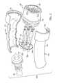
- FIG. 1is a perspective view of a connector assembly according to an embodiment illustrated in cooperation with a vehicle and a power supply;
- FIG. 2is an exploded perspective view of the connector assembly of FIG. 1 ;
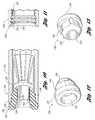
- FIG. 3is a perspective of a receptacle assembly of the connector assembly of FIG. 1 ;
- FIG. 4is an enlarged partial section view of a distal end of the receptacle assembly of FIG. 3 ;
- FIG. 5is another enlarged partial section view of the distal end of the receptacle assembly of FIG. 3 ;
- FIG. 6is an enlarged front perspective view of a retainer of the receptacle assembly of FIG. 3 ;
- FIG. 7is another enlarged rear perspective view of the retainer of FIG. 6 ;
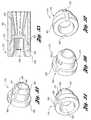
- FIG. 8is a partial section perspective view of a receptacle assembly according to another embodiment
- FIG. 9is a perspective view of a retainer of the receptacle assembly of FIG. 8 ;
- FIG. 10is a partial section view of a receptacle assembly according to another embodiment
- FIG. 11is an enlarged partial section view of a distal end of a receptacle of the receptacle assembly of FIG. 10 ;
- FIG. 12is a front perspective view of a retainer of the receptacle assembly of FIG. 10 ;
- FIG. 13is a rear perspective view of the retainer of FIG. 12 ;
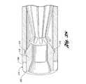
- FIG. 14is a perspective view of a receptacle assembly according to another embodiment
- FIG. 15is a section view of the receptacle assembly of FIG. 14 ;
- FIG. 16is an enlarged section view of a distal end of the receptacle assembly of FIG. 14 ;
- FIG. 17is an enlarged rear perspective view of a retainer of the receptacle assembly of FIG. 14 ;
- FIG. 18is a section view of a receptacle assembly according to at least one embodiment
- FIG. 19is an enlarged section view of a distal end of the receptacle assembly of FIG. 18 ;
- FIG. 20is a enlarged perspective view of a distal end of a retainer of the receptacle assembly of FIG. 18 ;
- FIG. 21is an enlarged partial section perspective view of the retainer of FIG. 20 ;
- FIG. 22is a perspective view of a receptacle assembly according to another embodiment
- FIG. 23is an enlarged front perspective view of a retainer of the receptacle assembly of FIG. 22 ;
- FIG. 24is an enlarged rear perspective view of the retainer of FIG. 23 ;
- FIG. 25is an enlarged section view of a distal end of the receptacle assembly of FIG. 22 ;
- FIG. 26is a perspective view of a receptacle assembly according to another embodiment
- FIG. 27is a section view of the receptacle assembly of FIG. 26 ;
- FIG. 28is an enlarged section view of a retainer of the receptacle assembly of FIG. 26 ;
- FIG. 29is a perspective view of a retainer according to an embodiment
- FIG. 30is a perspective view of a distal end of a receptacle assembly according to another embodiment, illustrated with the retainer of FIG. 29 ;
- FIG. 31is an enlarged partial section view of the distal end of the receptacle assembly of FIG. 30 ;
- FIG. 32is an enlarged partial section perspective view of the distal end of the receptacle assembly of FIG. 30 ;
- FIG. 33is a rear perspective view of a retainer according to an embodiment
- FIG. 34is a front perspective view of the retainer of FIG. 33 ;
- FIG. 35is a partial section view of a receptacle assembly according to an embodiment, illustrated with the retainer of FIG. 33 ;
- FIG. 36is a rear perspective view of a retainer according to an embodiment
- FIG. 37is a front perspective view of the retainer of FIG. 36 ;
- FIG. 38is an enlarged partial section perspective view of a receptacle assembly according to another embodiment, illustrated with the retainer of FIG. 36 ;
- FIG. 39is a perspective view of a receptacle assembly according to another embodiment.
- FIG. 40is an enlarged perspective view of a guide of the receptacle assembly of FIG. 39 ;
- FIG. 41is an enlarged perspective view of a retainer of the receptacle assembly of FIG. 39 ;
- FIG. 42is an enlarged section view of a distal end of the receptacle assembly of FIG. 39 ;
- FIG. 43is a section view of a receptacle assembly according to another embodiment.
- FIG. 44is an enlarged partial section perspective view of a proximal end of the receptacle assembly of FIG. 43 ;
- FIG. 45is an enlarged partial section view of a distal end of the receptacle assembly of FIG. 43 .
- a connector assembly for facilitating electric charging of a vehicleis illustrated in accordance with an embodiment and is referenced generally by numeral 120 .
- the connector assembly 120may be configured to accommodate a number of different electrical harness configurations by interchanging a couple components.
- the connector assembly 120is included in a cordset assembly 122 , according to one or more embodiments.
- the cordset assembly 122includes a connector for connecting to an external power supply 124 for receiving electrical energy.
- the external power supply 124represents an alternating current (AC) electrical power supply, such as a standard residential power circuit.
- the cord set assembly 122includes electric vehicle supply equipment (EVSE) 126 and a charging cable 128 .
- the charging cable 128extends between the EVSE 126 and the connector assembly 120 .
- the EVSE 126is configured to monitor electrical energy passing through the cable 128 during charging.
- the cordset assembly 122may be configured to be portable (as shown in FIG. 1 ) or fixed to a charging station (not shown).
- the connector assembly 120attaches to a “plug-in” vehicle 130 , such as a hybrid electric vehicle, for supplying electrical energy to the vehicle 130 .
- vehicle 130includes a vehicle charging receptacle 132 that is connected to a battery 134 for receiving and storing electrical energy.
- the vehicle charging receptacle 132is mounted to be externally accessible from the vehicle 130 .
- the vehicle receptacle 132receives the connector assembly 120 .
- the battery 134is electrically connected to the charging receptacle 132 for storing electrical power.
- the vehicle 130may also include a converter (not shown) for converting AC to DC electrical power for storage in the battery 134 .
- the vehicle 130may be an electric vehicle, or any suitable vehicle that receives external electric power.
- the connector assembly 120is illustrated exploded for revealing the various components.
- the connector assembly 120includes a first housing portion 136 that has an external plug 138 that is sized to be received within the vehicle charging receptacle 132 .
- the receptacle housing portion 136includes a plurality of recessed sockets 140 that are each sized to receive an electrical connector, such as a receptacle assembly 142 .
- the receptacle assemblies 142are female electrical connectors that are inserted into the sockets 140 and retained into the sockets 140 by a backing plate 144 that is fastened to the receptacle housing portion 136 by fasteners 146 .
- the receptacles 142receive a plurality of pins (not shown) that are recessed within the vehicle charging receptacle 132 as is known in the art.
- the receptacle assemblies 142are aligned with the pins and the pins are received within the sockets 140 and consequently the receptacle assemblies 142 making electrical connection between the cordset assembly 122 and the vehicle 130 .
- female receptacle assemblies 142are illustrated and described, the invention contemplates any conductive connectors for the connector assembly 120 .
- the sockets 140may retain male pin connectors.
- the connector assembly 120includes a second housing portion 148 and a third housing portion 150 .
- the second housing portion 148 and the third housing portion 150are similar, yet mirror images of each other, for assembly in a clamshell configuration for retaining the cable 128 and the first housing portion 136 .
- the housing portions 136 , 148 , 150collectively provide a handle for manual manipulation of the connector assembly 120 .
- the second and third housing portions 148 , 150collectively provide an exterior 176 for the connector assembly 120 , and each include a cavity 178 , 180 .
- Wires 182extend from the cable 128 within the cavity 178 , 180 , through apertures 183 ; and are connected to the receptacle assemblies 142 .
- the receptacle assembly 142includes a longitudinal housing 184 with a receptacle 186 formed therein.
- the receptacle 186is illustrated in FIGS. 4 and 5 .
- the receptacle 186includes an opening 190 at a distal end 188 of the housing 184 .
- An electrically conductive terminal(not shown) is received within the receptacle 186 .
- a retainer 192is illustrated in FIGS. 3-7 , which acts a partial cap for retaining the terminal within the receptacle 186 .
- the retainer 192includes a longitudinal body 194 with an array of extensions or bosses 196 received within the receptacle for engagement with, and retention of, the terminal.
- the guide body 194has an aperture 198 formed through the body 194 and through the array of bosses 196 .
- the aperture 198is sized to receive a pin through the aperture 198 for electrical contact with the terminal.
- the body 194 and the bosses 196collectively provide a guide for guiding the pin into alignment and contact with the terminal.
- An array of fasteners 200extends from the guide body 194 into the receptacle 186 .
- the fasteners 200are also bosses that have an overall outer diameter that is greater than an inner diameter of the receptacle 186 to provide an interference fit or press fit within the receptacle 186 thereby retaining the retainer 192 to the receptacle housing 184 , and consequently retaining the terminal in the receptacle 186 .
- the fasteners 200are spaced apart from the aperture 198 so that deformation of the fasteners 200 after installation does not affect the guide provided by the guide bosses 196 and the aperture 198 . Further, the guide bosses 196 are not in direct contact with the fasteners 200 , and are not in direct contact with the receptacle housing 184 for providing a guide for the male pin without being affected by the installation of the retainer 192 to the receptacle 186 .
- the retainer 192includes a shoulder 202 that extends transversely and engages the distal end 188 of the receptacle housing 184 to position the guide body 194 relative to the receptacle 186 .
- the aperture 198is formed through the shoulder 202 whereby the shoulder 202 contributes to the guide body 194 .
- the arrays of the bosses 196 and fasteners 200extend form the shoulder 202 .
- the terminalprovides contact with the male pin that is sufficient to maintain electrical contact, without causing undue wear to the terminal or pin. Isolating the fastening feature from the guiding feature ensures adequate retention without disrupting the guidance and alignment of the pin.
- the retainermay be formed from any suitable material, conductive or insulated depending on the application requirements. The terminal provides electrical contact between the pin and the housing 184 .
- FIG. 8illustrates a receptacle assembly 204 according to another embodiment.
- the receptacle assembly 204includes a housing 206 with a receptacle 208 formed therein.
- a groove 210is formed within the receptacle 208 .
- a terminal 212is received within the receptacle 208 .
- a retainer 214is provided with a guide body 216 received within the receptacle 208 .
- the retainer 214is also illustrated in FIG. 9 .
- a shoulder 218extends from the retainer 214 .
- An array of lugs 220extend from the guide body 216 and are received within the groove 210 for locking and retaining the retainer 214 to the receptacle 208 .
- the lugs 220may be oversized within the groove 210 to provide an additional interference fit. Additionally, the guide body 216 may be oversized relative to the receptacle 208 to provide an additional interference fit. The lugs 220 are spaced about the periphery to distribute any load caused in installation to minimize deflection to an aperture 222 within the guide body 216 .
- FIG. 10illustrates a receptacle assembly 224 according to at least one embodiment.
- the receptacle assembly 224includes a housing 226 with a receptacle 228 formed therein.
- a plurality of grooves 230are formed within the receptacle 228 as also illustrated in FIG. 11 .
- the grooves 230are angled to provide barbed edges 232 facing away from an opening 234 of the receptacle 228 .
- FIGS. 10 , 12 and 13illustrate a retainer 236 with a body 238 and a shoulder 240 .
- An aperture 242is formed through the body 238 and the shoulder 240 .
- An array of ribs 244are provided on the body 238 , which are oversized relative to the receptacle 228 .
- the ribs 244engage the grooves 230 during insertion and are retained by the barbed edges 232 .
- the barbed edges 232inhibit disassembly of the retainer 236 form the receptacle 228 and control a force required to install the retainer 236 .
- FIGS. 14-16illustrate a receptacle assembly 246 according to at least another embodiment.
- the receptacle assemblyincludes a housing 248 with a receptacle 250 .
- a retainer 252is illustrated in FIGS. 14-17 with a body 254 received within the receptacle 250 .
- the body 254is undersized relative to the receptacle 250 to provide a clearance or slip fit.
- a shoulder 256extends across an opening 258 of the receptacle 250 in the housing 248 .
- a sleeve 260extends partially over the housing 248 form the shoulder 256 .
- An inner diameter of the sleeve 260is undersized relative to an outer diameter of the housing 248 to provide an interference fit of the retainer 252 upon the housing 248 .
- the sleeve 260avoids deformation to the guide body 254 and an aperture 262 within the guide body 254 .
- FIGS. 18 and 19illustrate a receptacle assembly 264 according to another embodiment.
- a receptacle housing 266is provided with a receptacle 268 formed within the housing 266 .
- a retainer 270is provided with a guide body 272 extending into the receptacle 268 with clearance therebetween. The retainer 270 is illustrated in FIGS. 18-21 .
- a shoulder 274extends across an opening 276 of the receptacle 268 .
- a sleeve 278extends over the receptacle housing 266 .
- the sleeve 278includes an inner diameter that is undersized relative to the receptacle 268 to provide an interference fit with the receptacle 268 for retention of the receptacle 268 therein.
- the sleeve 278includes an array of notches 280 formed therein external of a distal end 282 of the receptacle housing 266 to permit deformation during installation without disrupting an aperture 284 within the guide body 272 .
- the sleeve 278may be a socket 140 in the first housing portion 136 thereby eliminating a separate retainer and minimizing parts.
- FIGS. 22-25illustrate an exterior connecting snap-fit end cap 286 in accordance with one non-limiting aspect of the present invention.
- the end cap 286may be similarly configured to the retainers shown above with respect to having an end stop portion 288 and an inserted portion 290 .
- An opening 292extends through the end stop portion 288 , and the inserted portion 290 to facilitate guiding the connector into the resilient element (not shown).
- the opening 292may be sized to provide a tapered opening that narrows to more closely align with the connector.
- the end cap 286may include a plurality of snap fingers 294 , 296 , 298 , 300 defined by corresponding channels 302 , 304 (only one channel set is labeled) within an overlapping portion 306 extending beyond the end stop portion 288 .
- the snap fingers 294 , 296 , 298 , 300are shown to include fingers 308 , 310 that have a tip 312 with a leading edge 314 for extension of the snap fingers 294 , 296 , 298 , 300 during installation.
- Each tip 312is retained within a channel 316 included on an exterior portion of a housing 318 .
- Each tip 312may include an abutment edge 320 for engaging the channel 316 .
- the configuring of the snap fingers 294 , 296 , 298 , 300 to engage an exterior portion of the connector 318may be beneficial in facilitating removal of the end cap 286 without having to use a tool, i.e., the tool may be required to remove the interior connecting end caps.
- Reliefs 322 , 324 , 326 , 328may be included in the overlapping portion 306 rearwardly of the tips 312 of the fingers 294 , 296 , 298 , 300 .
- the reliefs 322 , 324 , 326 , 328may be provided to facilitate removal of the end cap 286 from a molding tool without having to open the molding tool.
- the housing 318 shown in FIG. 25includes a chamfered leading edge 330 that cooperates with a correspondingly chamfered leading edge 332 of the inserted portion 290 of the end cap 286 . These chamfered edges 330 , 332 may be helpful facilitating insertion of the end cap 286 within the recessed end of the housing 318 .
- the end cap 286is shown to include four equally spaced snap fingers 294 , 296 , 298 , 300 , however, the end cap 286 may include any number of snap fingers 294 , 296 , 298 , 300 without deviating from the scope contemplated by the present invention.
- the end cap 286may be comprised of a suitable conducting or non-conducting material.
- the end cap 286 shown in FIGS. 22-25includes the overlapping portion 306 extending a slight distance over the housing 318 .
- FIGS. 26-28illustrate an end cap 334 where an overlapping portion 336 , similar to the overlapping portion 306 shown in FIGS. 22-25 , extends approximately the entire length of a first recess 338 and to an area proximate a second recessed 340 end to form a sleeve/housing.
- This sleeve-type of end cap 334may be integrated within a socket 140 of the connector assembly 120 .
- FIGS. 29-32illustrate an interior connecting snap-fit end cap 342 operable to be added to one of the receptacle housings noted above or other similarly recessed terminals in accordance with one non-limiting aspect of the present invention.
- the end cap 342may be configured to be positioned outboard of a resilient element 344 .
- the end cap 342may be configured to have a length sufficient to pre-load the resilient element 344 such that it at least partially compresses the resilient element 344 toward a rearward wall of a recessed end 346 , which may be beneficial protecting the contact beams and compensating for manufacturing tolerances.
- the end cap 342may be configured to prevent removal of the resilient element 344 from a recessed end.
- the end cap 342may include an end stop 348 having a width ESW slightly larger than an outer width of the recessed end 346 in order to control how far the end cap 342 is able to insert.
- the end cap 342includes an opening 350 to permit passage of a connector (not shown).
- the opening 350may include a slightly larger width OW at a beginning portion and then taper down thereafter to a width EW approximately equal to the width of the connector.
- the width EWmay be selected to provide an interference fit with the connector, although it is not necessary that an interference fit be provided as the end cap 342 may be used simply to guide the connector into the resilient element/recessed end 344 , 346 .
- a narrowest width NW of the resilient element 344 at a tip portionmay be selected to be slightly smaller than the width EW of the opening 350 and/or the connector in order to ensure a sufficient electrical connection between the resilient element 344 and the connector.
- the exterior width ESW of the end stop 348may be sized to correspond with an exterior width of a housing 352 in order to provide a flush exterior surface.
- the snap-fit end cap 342may be comprised of a conducting or non-conducting material, such as but not limited to plastic or rubber.
- the materialmay be selected to be of a type sufficient to facilitate use of a plurality of snap fingers 354 .
- the snap fingers 354may be defined by channels 356 included within an inserted portion 358 of the end cap 342 .
- the end of the snap fingers 354may be shaped into a finger 360 .
- the finger 360may snap into a corresponding recessed channel 362 of the recessed end 346 .
- the recessed channel 362may include a width RW slightly larger than a width of the recessed end 346 at an outer portion 364 and a width of the recessed end at an inner portion 366 .
- the width of the recessed end 346 at the outer portion 364is shown to be equal to the width of the inner portion 366 , it may be larger or smaller depending on design consideration of the end cap 342 , e.g., the width of the outer portion 364 may be larger than the inner portion 366 in the event the material characteristics of the end cap 342 require more material to facilitate the contemplated flexing of the snap finger 354 , which may be required in the event the recessed end is relatively narrow.
- a recess 368may be included rearward of a tip of each finger 360 to facilitate molding of the end cap 342 .
- the recesses 368may be sized to approximate the height of the tip so that the end cap 342 can be laterally removed from a molding tool without having to open the tool. This may be beneficial in limiting tooling cost and associated manufacturing cost.
- embodiments of the present inventionare not necessarily limited to this configuration and fully contemplate molding at least the end stop portion 348 without the recesses 368 so that a continuous ring of material can be provided.
- the snap-fit end cap 342is shown to include three snap fingers 354 equidistantly spaced about the inserted portion 358 .
- FIGS. 33-35illustrate an alternative embodiment of a snap-fit end cap 370 where a single snap finger 372 is included.
- the use of the single snap finger 372 configurationmay be beneficial with narrower connectors and/or terminals where it may not be feasible to maintain the structural integrity of the end cap 370 while permitting the use of multiple snap fingers 372 .
- FIGS. 36-38illustrate an alternative embodiment of a snap-fit end cap 374 similarly configured to the end cap 342 except for having channels 356 removed.
- a finger tip 376instead extends outwardly from an inserted portion 378 to facilitate the snap fit.
- This configurationmay require the size and shape of the end cap 374 and/or its material composition to allow some flexing or bending during insertion so that the finger tip 376 can compress within the outer portion 364 of the inner recess 368 , and thereafter, decompress to be retained within the channel 362 .
- FIGS. 36-38illustrate an alternative embodiment of a snap-fit end cap 374 similarly configured to the end cap 342 except for having channels 356 removed.
- a finger tip 376instead extends outwardly from an inserted portion 378 to facilitate the snap fit.
- This configurationmay require the size and shape of the end cap 374 and/or its material composition to allow some flexing or bending during insertion so that the finger tip 376 can compress within the outer portion 364 of the
- an area 380 behind the finger tip 376is shown to be removed to form recesses 380 within an end stop portion 382 in order to facilitate removal from a mold tool.
- this materialmay not necessarily be removed.
- the embodiment shown in FIGS. 36-38includes two fingers 376 to demonstrate the present invention contemplating the end cap including one, two, three or some other number of snap fingers.
- FIG. 39illustrates a receptacle assembly 384 according to another embodiment.
- the receptacle assembly 384includes a housing 386 with a receptacle 388 for retention of a terminal.
- a dual material (or two-shot) retainer 392is provided, which is also illustrated in FIGS. 39-42 .
- a guide body 394is formed from a first material, such as a polymeric material which is hard enough to guide the pin.
- the guide body 394includes a shoulder 396 with an aperture 398 formed therethrough.
- a series of projections 400are provided on the shoulder 396 .
- a softer fastener layer 402such as an elastomer, is overmolded onto the projections 400 to bond to the projections 400 .
- the fastener layer 402includes a shell 404 with a leading edge 406 for clearing the housing 386 , and an abutment edge 408 for engaging the groove 390 . Additional channels for designed flexibility are not required due to the flexibility of the fastener layer 402 .
- FIGS. 43-45illustrate a receptacle assembly 410 according to another embodiment with a receptacle housing 412 with a receptacle 414 .
- a guide body 416is received within the receptacle with a slip or clearance fit.
- a shoulder 418extends from the guide body 416 ; and a sleeve 420 extends over the housing 412 , also with a clearance fit.
- the sleeve 420is formed integral with the first housing portion 136 as a socket 140 .
- the backing plate 144is fastened to the first housing portion 136 thereby retaining the receptacle housing 412 within the socket 140 .
- the present inventioncontemplates using any one or more of the foregoing terminals within any type of electrical assembly or adding the end cap to other connectors/terminals, and particularly, using the terminals and/or the end caps within a vehicle charger connector assembly.
Landscapes
- Engineering & Computer Science (AREA)
- Mechanical Engineering (AREA)
- Power Engineering (AREA)
- Transportation (AREA)
- Connector Housings Or Holding Contact Members (AREA)
Abstract
Description
Claims (14)
Priority Applications (6)
| Application Number | Priority Date | Filing Date | Title |
|---|---|---|---|
| US13/588,542US8808039B2 (en) | 2011-08-22 | 2012-08-17 | Connector assembly and terminal retainer |
| DE102012016641.9ADE102012016641B4 (en) | 2011-08-22 | 2012-08-21 | Recording arrangement and connection holder |
| CN201510418809.0ACN104993272B (en) | 2011-08-22 | 2012-08-22 | Connector assembly and therminal retainer |
| CN201210307017.2ACN102957023B (en) | 2011-08-22 | 2012-08-22 | Connector Assemblies and Terminal Retainers |
| US14/329,411US9352708B2 (en) | 2011-08-22 | 2014-07-11 | Connector assembly and terminal retainer |
| US15/148,125US9761983B2 (en) | 2011-08-22 | 2016-05-06 | Connector assembly and terminal retainer |
Applications Claiming Priority (2)
| Application Number | Priority Date | Filing Date | Title |
|---|---|---|---|
| US201161525881P | 2011-08-22 | 2011-08-22 | |
| US13/588,542US8808039B2 (en) | 2011-08-22 | 2012-08-17 | Connector assembly and terminal retainer |
Related Child Applications (1)
| Application Number | Title | Priority Date | Filing Date |
|---|---|---|---|
| US14/329,411DivisionUS9352708B2 (en) | 2011-08-22 | 2014-07-11 | Connector assembly and terminal retainer |
Publications (2)
| Publication Number | Publication Date |
|---|---|
| US20130052854A1 US20130052854A1 (en) | 2013-02-28 |
| US8808039B2true US8808039B2 (en) | 2014-08-19 |
Family
ID=47665301
Family Applications (3)
| Application Number | Title | Priority Date | Filing Date |
|---|---|---|---|
| US13/588,542Active2032-09-21US8808039B2 (en) | 2011-08-22 | 2012-08-17 | Connector assembly and terminal retainer |
| US14/329,411Expired - Fee RelatedUS9352708B2 (en) | 2011-08-22 | 2014-07-11 | Connector assembly and terminal retainer |
| US15/148,125ActiveUS9761983B2 (en) | 2011-08-22 | 2016-05-06 | Connector assembly and terminal retainer |
Family Applications After (2)
| Application Number | Title | Priority Date | Filing Date |
|---|---|---|---|
| US14/329,411Expired - Fee RelatedUS9352708B2 (en) | 2011-08-22 | 2014-07-11 | Connector assembly and terminal retainer |
| US15/148,125ActiveUS9761983B2 (en) | 2011-08-22 | 2016-05-06 | Connector assembly and terminal retainer |
Country Status (3)
| Country | Link |
|---|---|
| US (3) | US8808039B2 (en) |
| CN (2) | CN104993272B (en) |
| DE (1) | DE102012016641B4 (en) |
Cited By (10)
| Publication number | Priority date | Publication date | Assignee | Title |
|---|---|---|---|---|
| USD750954S1 (en)* | 2014-07-31 | 2016-03-08 | B&B Molders LLC | Snap finger assembly |
| US20160126651A1 (en)* | 2014-10-31 | 2016-05-05 | Yazaki Corporation | Female terminal |
| US9680247B1 (en)* | 2016-03-04 | 2017-06-13 | Lear Corporation | Round terminal with low profile cap |
| US9853392B2 (en) | 2015-09-25 | 2017-12-26 | Caterpiller Inc. | Connector guard |
| DE102017210997A1 (en) | 2016-09-19 | 2018-03-22 | Lear Corporation | Connector devices for loading vehicles |
| US10148028B1 (en)* | 2017-05-17 | 2018-12-04 | Yazaki Corporation | Terminal for round pin-shaped electrical contact |
| US20200059035A1 (en)* | 2017-02-24 | 2020-02-20 | Fct Electronic Gmbh | Plug-in connector |
| US10855014B1 (en)* | 2019-07-15 | 2020-12-01 | Dinkle Enterprise Co., Ltd. | Connector used with high-current terminal |
| USD953145S1 (en)* | 2019-02-04 | 2022-05-31 | Biamp Systems, LLC | Snap plug |
| US20230056363A1 (en)* | 2020-01-16 | 2023-02-23 | Phoenix Contact E-Mobility Gmbh | Contact element assembly for a plug connector part |
Families Citing this family (24)
| Publication number | Priority date | Publication date | Assignee | Title |
|---|---|---|---|---|
| US9325095B2 (en) | 2011-05-05 | 2016-04-26 | Lear Corporation | Female type contact for an electrical connector |
| US8876562B2 (en) | 2011-05-05 | 2014-11-04 | Lear Corporation | Female type contact for an electrical connector |
| US8840436B2 (en) | 2011-05-05 | 2014-09-23 | Lear Corporation | Electrically conducting terminal |
| US8808039B2 (en) | 2011-08-22 | 2014-08-19 | Lear Corporation | Connector assembly and terminal retainer |
| US8858264B2 (en)* | 2012-11-28 | 2014-10-14 | Lear Corporation | Electrical terminal retainer and receptacle assembly |
| ES2635625T3 (en)* | 2013-07-30 | 2017-10-04 | Abb Schweiz Ag | Connection device for a switching device |
| DE102013019882B4 (en)* | 2013-11-28 | 2025-10-02 | Phoenix Contact E-Mobility Gmbh | Charging cable plug |
| US9821671B2 (en)* | 2014-03-04 | 2017-11-21 | Lear Corporation | Wall plug system for electric vehicle |
| US9929493B2 (en) | 2015-07-22 | 2018-03-27 | Appleton Grp Llc | Multiposition ground/earth terminal block for electrical receptacles |
| DE102015122303B3 (en)* | 2015-12-15 | 2017-04-20 | Amphenol-Tuchel Electronics Gmbh | connector socket |
| FR3048136B1 (en)* | 2016-02-18 | 2021-05-14 | Ilie Razvan | ELECTRICAL CONNECTOR CONTAINING A PLURALITY OF ELECTRICALLY CONDUCTIVE STRIPS |
| EP3309001B1 (en)* | 2016-10-14 | 2021-09-29 | EP Equipment Co., Ltd. | Battery plug-in device for material handling equipment |
| CN106410493A (en)* | 2016-11-18 | 2017-02-15 | 深圳市沃尔核材股份有限公司 | Heat radiating structure of charging gun |
| CN106532339B (en)* | 2016-12-20 | 2018-12-28 | 实盈电子(东莞)有限公司 | Charging gun with replaceable plug and assembling method thereof |
| WO2018203105A1 (en)* | 2017-05-02 | 2018-11-08 | Lemco Precision Sa | Female electrical contact and method for manufacturing same |
| DE102017213093A1 (en)* | 2017-07-28 | 2019-01-31 | Robert Bosch Gmbh | Electrical plug contact for high current applications and connector system for high current applications |
| CN109119806B (en)* | 2018-08-22 | 2024-05-24 | 安费诺精密连接器(深圳)有限公司 | Connector with a plurality of connectors |
| CN110061387B (en)* | 2019-05-28 | 2024-05-28 | 广东亿源通科技股份有限公司 | Connector assembly |
| KR102578186B1 (en)* | 2021-05-18 | 2023-09-13 | 주식회사 유라 | Charging connector for vehicle |
| KR102590201B1 (en)* | 2021-05-24 | 2023-10-17 | 주식회사 유라 | Car charging connector |
| CN113500926B (en)* | 2021-07-12 | 2024-02-13 | 浙江吉利控股集团有限公司 | Charging cable fastening device and charging pile for charging piles |
| NO347723B1 (en)* | 2021-11-12 | 2024-03-11 | Easee As | Electrical connector for an electric socket for an electric plug of a charging cable, an electric socket comprising such electrical connector, a charging station comprising such electric socket and methods of connecting an electrical connector |
| DE102022205204A1 (en) | 2022-02-03 | 2023-08-03 | Robert Bosch Gesellschaft mit beschränkter Haftung | Connector for a power cable |
| CN119895671A (en)* | 2022-09-15 | 2025-04-25 | 史陶比尔电子连接器股份公司 | Modular electrical connector assembly |
Citations (80)
| Publication number | Priority date | Publication date | Assignee | Title |
|---|---|---|---|---|
| CH151479A (en) | 1931-01-21 | 1931-12-15 | Weidmann H Ag | Plug contact for electrical lines. |
| FR997233A (en) | 1945-06-20 | 1952-01-03 | Vasselin & Cie Ets | Electric socket |
| US2912668A (en) | 1957-07-15 | 1959-11-10 | Television Associates Inc | Electrical socket connector |
| US3161451A (en)* | 1961-08-16 | 1964-12-15 | Multi Contact Neidecker & Co | Self-locking electric plug-and-jack connector |
| US3784965A (en)* | 1972-03-13 | 1974-01-08 | Electronic Molding Corp | Terminal construction |
| US4401359A (en)* | 1981-10-30 | 1983-08-30 | Eaton Corporation | Integrated wire termination system terminal with fastened retainer |
| US4572606A (en)* | 1983-11-25 | 1986-02-25 | Otto Dunkel Fabrik fur Elektrotechnische Gerate | Process for producing contact-spring bushes and a spring contact bush |
| US4714441A (en) | 1987-01-29 | 1987-12-22 | Amp Incorporated | Electrical socket |
| US4734063A (en)* | 1986-01-30 | 1988-03-29 | Joseph J. Koch | Radially resilient electric socket |
| US4826144A (en) | 1988-04-25 | 1989-05-02 | Peter J. Balsells | Inside back angle canted coil spring |
| US5106328A (en)* | 1990-08-01 | 1992-04-21 | Otto Dunkel Gmbh Fabrik Fur Elektrotechnische Gerate | Contact pin and bushing assembly |
| US5139276A (en) | 1988-04-25 | 1992-08-18 | Peter J. Balsells | Canted coil spring radially loaded while in a cavity |
| US5203813A (en)* | 1991-08-06 | 1993-04-20 | Airborn, Inc. | Low entry force connector socket method of manufacture |
| US5358224A (en) | 1991-02-14 | 1994-10-25 | Peter J. Balsells | Isolator mount assembly |
| US5449304A (en)* | 1994-05-19 | 1995-09-12 | The Whitaker Corporation | Electrical connector having improved contacts |
| US5474479A (en)* | 1994-09-28 | 1995-12-12 | The Whitaker Corporation | Louvered contact electrical connector |
| US5474309A (en) | 1993-06-11 | 1995-12-12 | Bal Seal Engineering Company, Inc. | Gasket assembly for sealing electromagnetic waves |
| US5588852A (en)* | 1995-03-21 | 1996-12-31 | The Whitaker Corporation | Electrical connector having socket contacts with safety shields |
| US5591039A (en)* | 1995-06-01 | 1997-01-07 | Elcon Products International | Socket contact with arc arresting member |
| US5667413A (en)* | 1995-11-13 | 1997-09-16 | Alcoa Fujikura Ltd. | Socket-type electrical connector |
| US5676571A (en)* | 1996-08-08 | 1997-10-14 | Elcon Products International | Socket contact with integrally formed hood and arc-arresting portion |
| US5730628A (en)* | 1996-09-25 | 1998-03-24 | Pacesetter, Inc. | Multi-contact connector for an implantable medical device |
| US5735716A (en)* | 1996-09-18 | 1998-04-07 | Yazaki Corporation | Electrical connectors with delayed insertion force |
| US5816643A (en) | 1993-07-12 | 1998-10-06 | Sumitomo Wiring Systems, Ltd. | Charge coupling for electric vehicle |
| DE19836196A1 (en) | 1997-08-11 | 1999-02-25 | Yazaki Corp | Heavy current terminal for charging electric vehicle |
| US5921803A (en)* | 1995-02-17 | 1999-07-13 | Yazaki Corporation | Terminal for charging connector |
| US6039614A (en)* | 1996-03-05 | 2000-03-21 | Ramari; Luigi | Fast coupling automatic latching connector releasable by movement of an external body |
| US6042432A (en)* | 1997-08-11 | 2000-03-28 | Yazaki Corporation | Terminal for charging with large current |
| DE19943373A1 (en) | 1998-09-10 | 2000-03-30 | Yazaki Corp | Plug socket terminal for heavy current e.g. for charging battery of electric vehicle, has cylindrical terminal body with plastics resin cap retaining cylindrical spring contact engaging inserted plug terminal |
| US6062919A (en)* | 1997-08-29 | 2000-05-16 | Thomas & Betts International, Inc. | Electrical connector assembly having high current-carrying capability and low insertion force |
| US6102751A (en) | 1998-03-05 | 2000-08-15 | Houston Geophysical Products, Inc. | Female socket assembly for electrical connector |
| US6102746A (en)* | 1999-04-30 | 2000-08-15 | Hypertronics Corporation | Coaxial electrical connector with resilient conductive wires |
| US6190215B1 (en) | 1997-01-31 | 2001-02-20 | Berg Technology, Inc. | Stamped power contact |
| US6250974B1 (en)* | 1998-06-25 | 2001-06-26 | Tri-Star Electronics International, Inc. | Hoodless electrical socket contact |
| US6264508B1 (en)* | 1999-11-30 | 2001-07-24 | Preci-Dip Durtal Sa | Female type contact piece enabling electrical contact with a male element |
| US6273766B1 (en)* | 2000-09-08 | 2001-08-14 | Eagle Comtronics, Inc. | Electronic device including a collet assembly with dual receiving sockets |
| US20020122690A1 (en) | 2001-03-05 | 2002-09-05 | Daniel Poon | Spring energized connector |
| US6464546B2 (en)* | 2000-08-17 | 2002-10-15 | Smiths Group Plc | Electrical contacts |
| US6482049B1 (en)* | 1999-07-16 | 2002-11-19 | Amphenol Corporation | Radially resilient electrical connector |
| US20030040228A1 (en) | 2001-08-27 | 2003-02-27 | Carlo Finzer | Electrical connector |
| US20030077950A1 (en)* | 2001-10-18 | 2003-04-24 | Swearingen Dean D. | Electrical connector grid anchor and method of making the same |
| US6752668B2 (en)* | 2002-08-14 | 2004-06-22 | Konnektech, Ltd. | Electrical connector |
| US6811453B2 (en)* | 2000-07-28 | 2004-11-02 | Roger C. Williams | Tine edge electrical contact |
| US20040245686A1 (en) | 2003-06-04 | 2004-12-09 | Balsells Peter J. | Spring latching connectors radially and axially mounted |
| US6835084B2 (en) | 2002-02-15 | 2004-12-28 | Bal Seal Engineering Co., Inc. | Medically implantable electrical connector with constant conductivity |
| US6837756B2 (en)* | 2001-10-05 | 2005-01-04 | Amphenol Corporation | Radially resilient electrical connector and method of making the same |
| US6848922B2 (en)* | 2003-03-10 | 2005-02-01 | Hypertronics Corporation | Socket contact with integrally formed arc arresting portion |
| DE102004002403B3 (en) | 2004-01-16 | 2005-07-14 | Tyco Electronics Amp Gmbh | Spring element, especially for contact socket, has contact tongues each consisting of two separate strips with cut-out between them and strips are connected together with radius at their outer and inner ends |
| US20050242910A1 (en) | 2004-04-29 | 2005-11-03 | Balsells Peter J | Contact assembly |
| US6966802B2 (en)* | 2003-02-11 | 2005-11-22 | Tyco Electroncis Amp Gmbh | Plug connector |
| US7191518B2 (en)* | 2002-02-28 | 2007-03-20 | Qa Technology Company, Inc. | Method of making a hyperboloid electrical contact |
| JP2007317403A (en) | 2006-05-23 | 2007-12-06 | Sumitomo Wiring Syst Ltd | Female terminal fitting |
| US7393252B2 (en) | 2005-08-04 | 2008-07-01 | Sourian | Female electrical contact element and method for making a female electrical contact element |
| US20080246231A1 (en) | 2007-04-09 | 2008-10-09 | Sjostedt Robbie J | Connector assembly for use with medical devices |
| US20080255631A1 (en) | 2007-04-11 | 2008-10-16 | Sjostedt Robbie J | Integrated header connector system |
| US20080254670A1 (en) | 2007-04-13 | 2008-10-16 | Balsells Peter J | Electrical connectors with improved electrical contact performance |
| US20090048638A1 (en) | 2007-08-15 | 2009-02-19 | Gerry Rey | Connector assembly for use with medical devices |
| US20090258519A1 (en) | 2008-04-11 | 2009-10-15 | Farshid Dilmaghanian | Connector cartridge stack for electrical transmission |
| US20090298356A1 (en)* | 2008-05-30 | 2009-12-03 | Zhan Li | Line Spring Jack and Its Assembly Method |
| US20100029127A1 (en) | 2008-07-31 | 2010-02-04 | Rob Sjostedt | Device for securing leads into in-line connector devices |
| US20100029145A1 (en) | 2008-07-30 | 2010-02-04 | Pete Balsells | Canted coil multi-metallic wire |
| WO2010060370A1 (en) | 2008-11-25 | 2010-06-03 | Byd Company Limited | Charging device for electrically drivable vehicle |
| US20100279558A1 (en) | 2009-04-29 | 2010-11-04 | Gordon Leon | Electrical contact assemblies with canted coil springs |
| US7845992B2 (en)* | 2008-01-31 | 2010-12-07 | Fci Americas Technology, Inc. | Electrical connector with contact arm preloading |
| US20100311266A1 (en) | 2009-06-05 | 2010-12-09 | Farshid Dilmaghanian | Dual directional connector |
| US20110034053A1 (en)* | 2008-11-21 | 2011-02-10 | Yazaki Corporation | Charging connector |
| US7909236B2 (en) | 2004-03-16 | 2011-03-22 | Erdie End Caps, Llc | End caps for tubes and shipping containers formed therefrom |
| US20110171850A1 (en)* | 2010-01-08 | 2011-07-14 | Lear Corporation | Connector assembly for electric vehicle charging |
| US20120003882A1 (en)* | 2010-07-02 | 2012-01-05 | Lear Corporation | Electrical terminal with coil spring |
| US20120003880A1 (en) | 2010-07-02 | 2012-01-05 | Lear Corporation | Stamped electrical terminal |
| US20120003883A1 (en) | 2010-07-02 | 2012-01-05 | Lear Corporation | Electrically conducting terminal |
| US20120000329A1 (en) | 2010-07-02 | 2012-01-05 | Lear Corporation | Arbor insertion tool |
| US20120282823A1 (en)* | 2011-05-05 | 2012-11-08 | Michael Glick | Female type contact for an electrical connector |
| US20120282797A1 (en)* | 2011-05-05 | 2012-11-08 | Lear Corporation | Electrically conducting terminal |
| US20130017739A1 (en)* | 2011-05-05 | 2013-01-17 | Lear Corporation | Female type contact for an electrical connector |
| US20130052854A1 (en)* | 2011-08-22 | 2013-02-28 | Lear Corporation | Connector assembly and terminal retainer |
| US8414339B1 (en)* | 2011-10-31 | 2013-04-09 | Lear Corporation | Electrical terminal and receptacle assembly |
| US8425253B2 (en)* | 2008-07-29 | 2013-04-23 | Belden Inc. | Center conductor terminal having increased contact resistance |
| US20130109237A1 (en)* | 2011-10-31 | 2013-05-02 | Lear Corporation | Electrical terminal and receptacle assembly |
| US20130337702A1 (en)* | 2012-06-19 | 2013-12-19 | Lear Corporation | Electrical receptacle assembly |
Family Cites Families (26)
| Publication number | Priority date | Publication date | Assignee | Title |
|---|---|---|---|---|
| US3161541A (en) | 1959-04-27 | 1964-12-15 | Gen Electric | Synthetic resin and conductors insulated therewith |
| US3059208A (en) | 1960-12-14 | 1962-10-16 | Amphenol Borg Electronics Corp | Coaxial connector socket assembly |
| CH569369A5 (en)* | 1973-09-10 | 1975-11-14 | Sotax Ag | Tubular plug connector socket - has three parallel spring fingers acting radially and held by collar clipping onto socket entrance |
| US4002400A (en) | 1975-08-01 | 1977-01-11 | E. I. Du Pont De Nemours And Company | Electrical connector |
| US4258970A (en) | 1979-03-05 | 1981-03-31 | The Bendix Corporation | Electrical cable and molded protection cap assembly |
| US4508413A (en) | 1982-04-12 | 1985-04-02 | Allied Corporation | Connector |
| US4679875A (en)* | 1985-12-09 | 1987-07-14 | Trw Inc. | Attachment of electric cable to submergible pump motor heads |
| US4734064A (en) | 1986-08-29 | 1988-03-29 | Amphenol Corporation | Electrical socket contact with convex engaging tines |
| US4934967A (en) | 1987-12-15 | 1990-06-19 | Amp Incorporated | Socket for pin grid array |
| JPH0412483A (en) | 1990-04-27 | 1992-01-17 | Kel Corp | Ic socket |
| EP0626104B1 (en) | 1992-02-12 | 1998-10-21 | Berg Electronics Manufacturing B.V. | Power port terminal |
| JP2567945Y2 (en) | 1993-03-11 | 1998-04-08 | 住友電装株式会社 | Protection cap for panel mounting connector |
| US5658175A (en) | 1995-10-05 | 1997-08-19 | Itt Corporation | One-piece hooded socket contact and method of producing same |
| US5938487A (en) | 1997-03-25 | 1999-08-17 | The Whitaker Corporation | Socket contact having tapered beam |
| FR2775389B1 (en) | 1998-02-24 | 2000-05-05 | Radiall Sa | CONTACT PIN OF AN ELECTRICAL CONNECTOR |
| SE517582C2 (en) | 1999-03-31 | 2002-06-25 | Berg Connectors Sweden Ab | socket |
| US6296970B1 (en) | 2000-01-21 | 2001-10-02 | Moltech Power Systems, Inc. | Connector assembly for connecting battery cells |
| US6899571B1 (en) | 2000-05-11 | 2005-05-31 | Konnektech Ltd. | Radially resilient electrical connector with welded grid |
| US7037127B2 (en) | 2000-07-28 | 2006-05-02 | Williams Roger C | Low force electrical contact |
| JP2002324621A (en)* | 2001-04-24 | 2002-11-08 | Yazaki Corp | connector |
| US7074096B2 (en) | 2003-10-30 | 2006-07-11 | Tyco Electronics Corporation | Electrical contact with plural arch-shaped elements |
| DE102006006845B3 (en) | 2006-02-15 | 2007-07-19 | Tyco Electronics Amp Gmbh | Electrical outer conductor sleeve for e.g. electrical angular -plug-in connector, has spring segment unilaterally connected with wall in single piece, where free longitudinal end section of segment partially protrudes inwardly into sleeve |
| US20100191299A1 (en)* | 2009-01-27 | 2010-07-29 | Mark Ayzenberg | Electrical Contact of Biocompatible Material |
| US7892050B2 (en) | 2009-06-17 | 2011-02-22 | Lear Corporation | High power fuse terminal with scalability |
| US7878866B1 (en) | 2010-07-02 | 2011-02-01 | Lear Corporation | Connector assembly for vehicle charging |
| CN102005679A (en)* | 2010-12-10 | 2011-04-06 | 怡达电气(苏州)有限公司 | Electric motor car charging connector |
- 2012
- 2012-08-17USUS13/588,542patent/US8808039B2/enactiveActive
- 2012-08-21DEDE102012016641.9Apatent/DE102012016641B4/ennot_activeExpired - Fee Related
- 2012-08-22CNCN201510418809.0Apatent/CN104993272B/ennot_activeExpired - Fee Related
- 2012-08-22CNCN201210307017.2Apatent/CN102957023B/ennot_activeExpired - Fee Related
- 2014
- 2014-07-11USUS14/329,411patent/US9352708B2/ennot_activeExpired - Fee Related
- 2016
- 2016-05-06USUS15/148,125patent/US9761983B2/enactiveActive
Patent Citations (88)
| Publication number | Priority date | Publication date | Assignee | Title |
|---|---|---|---|---|
| CH151479A (en) | 1931-01-21 | 1931-12-15 | Weidmann H Ag | Plug contact for electrical lines. |
| FR997233A (en) | 1945-06-20 | 1952-01-03 | Vasselin & Cie Ets | Electric socket |
| US2912668A (en) | 1957-07-15 | 1959-11-10 | Television Associates Inc | Electrical socket connector |
| US3161451A (en)* | 1961-08-16 | 1964-12-15 | Multi Contact Neidecker & Co | Self-locking electric plug-and-jack connector |
| US3784965A (en)* | 1972-03-13 | 1974-01-08 | Electronic Molding Corp | Terminal construction |
| US4401359A (en)* | 1981-10-30 | 1983-08-30 | Eaton Corporation | Integrated wire termination system terminal with fastened retainer |
| US4572606A (en)* | 1983-11-25 | 1986-02-25 | Otto Dunkel Fabrik fur Elektrotechnische Gerate | Process for producing contact-spring bushes and a spring contact bush |
| US4734063A (en)* | 1986-01-30 | 1988-03-29 | Joseph J. Koch | Radially resilient electric socket |
| US4714441A (en) | 1987-01-29 | 1987-12-22 | Amp Incorporated | Electrical socket |
| US4826144A (en) | 1988-04-25 | 1989-05-02 | Peter J. Balsells | Inside back angle canted coil spring |
| US5139276A (en) | 1988-04-25 | 1992-08-18 | Peter J. Balsells | Canted coil spring radially loaded while in a cavity |
| US5106328A (en)* | 1990-08-01 | 1992-04-21 | Otto Dunkel Gmbh Fabrik Fur Elektrotechnische Gerate | Contact pin and bushing assembly |
| US5358224A (en) | 1991-02-14 | 1994-10-25 | Peter J. Balsells | Isolator mount assembly |
| US5203813A (en)* | 1991-08-06 | 1993-04-20 | Airborn, Inc. | Low entry force connector socket method of manufacture |
| US5474309A (en) | 1993-06-11 | 1995-12-12 | Bal Seal Engineering Company, Inc. | Gasket assembly for sealing electromagnetic waves |
| US5599027A (en) | 1993-06-11 | 1997-02-04 | Bal Seal Engineering Company, Inc. | Gasket assembly for sealing electromagnetic waves |
| US5816643A (en) | 1993-07-12 | 1998-10-06 | Sumitomo Wiring Systems, Ltd. | Charge coupling for electric vehicle |
| US5449304A (en)* | 1994-05-19 | 1995-09-12 | The Whitaker Corporation | Electrical connector having improved contacts |
| US5474479A (en)* | 1994-09-28 | 1995-12-12 | The Whitaker Corporation | Louvered contact electrical connector |
| US5921803A (en)* | 1995-02-17 | 1999-07-13 | Yazaki Corporation | Terminal for charging connector |
| US5588852A (en)* | 1995-03-21 | 1996-12-31 | The Whitaker Corporation | Electrical connector having socket contacts with safety shields |
| US5591039A (en)* | 1995-06-01 | 1997-01-07 | Elcon Products International | Socket contact with arc arresting member |
| US5667413A (en)* | 1995-11-13 | 1997-09-16 | Alcoa Fujikura Ltd. | Socket-type electrical connector |
| US6039614A (en)* | 1996-03-05 | 2000-03-21 | Ramari; Luigi | Fast coupling automatic latching connector releasable by movement of an external body |
| US5676571A (en)* | 1996-08-08 | 1997-10-14 | Elcon Products International | Socket contact with integrally formed hood and arc-arresting portion |
| US5735716A (en)* | 1996-09-18 | 1998-04-07 | Yazaki Corporation | Electrical connectors with delayed insertion force |
| US5730628A (en)* | 1996-09-25 | 1998-03-24 | Pacesetter, Inc. | Multi-contact connector for an implantable medical device |
| US6190215B1 (en) | 1997-01-31 | 2001-02-20 | Berg Technology, Inc. | Stamped power contact |
| DE19836196A1 (en) | 1997-08-11 | 1999-02-25 | Yazaki Corp | Heavy current terminal for charging electric vehicle |
| US6042432A (en)* | 1997-08-11 | 2000-03-28 | Yazaki Corporation | Terminal for charging with large current |
| US6062919A (en)* | 1997-08-29 | 2000-05-16 | Thomas & Betts International, Inc. | Electrical connector assembly having high current-carrying capability and low insertion force |
| US6102751A (en) | 1998-03-05 | 2000-08-15 | Houston Geophysical Products, Inc. | Female socket assembly for electrical connector |
| US6250974B1 (en)* | 1998-06-25 | 2001-06-26 | Tri-Star Electronics International, Inc. | Hoodless electrical socket contact |
| DE19943373A1 (en) | 1998-09-10 | 2000-03-30 | Yazaki Corp | Plug socket terminal for heavy current e.g. for charging battery of electric vehicle, has cylindrical terminal body with plastics resin cap retaining cylindrical spring contact engaging inserted plug terminal |
| US6254439B1 (en)* | 1998-09-10 | 2001-07-03 | Yazaki Corporation | Female type terminal, assembling method of female type terminal, and connector for female type terminal |
| US6102746A (en)* | 1999-04-30 | 2000-08-15 | Hypertronics Corporation | Coaxial electrical connector with resilient conductive wires |
| US6482049B1 (en)* | 1999-07-16 | 2002-11-19 | Amphenol Corporation | Radially resilient electrical connector |
| US6264508B1 (en)* | 1999-11-30 | 2001-07-24 | Preci-Dip Durtal Sa | Female type contact piece enabling electrical contact with a male element |
| US6811453B2 (en)* | 2000-07-28 | 2004-11-02 | Roger C. Williams | Tine edge electrical contact |
| US6464546B2 (en)* | 2000-08-17 | 2002-10-15 | Smiths Group Plc | Electrical contacts |
| US6273766B1 (en)* | 2000-09-08 | 2001-08-14 | Eagle Comtronics, Inc. | Electronic device including a collet assembly with dual receiving sockets |
| US20020122690A1 (en) | 2001-03-05 | 2002-09-05 | Daniel Poon | Spring energized connector |
| US20030040228A1 (en) | 2001-08-27 | 2003-02-27 | Carlo Finzer | Electrical connector |
| US6837756B2 (en)* | 2001-10-05 | 2005-01-04 | Amphenol Corporation | Radially resilient electrical connector and method of making the same |
| US20030077950A1 (en)* | 2001-10-18 | 2003-04-24 | Swearingen Dean D. | Electrical connector grid anchor and method of making the same |
| US7048596B2 (en)* | 2001-10-18 | 2006-05-23 | Konnektech, Ltd. | Electrical connector grid anchor and method of making the same |
| US6835084B2 (en) | 2002-02-15 | 2004-12-28 | Bal Seal Engineering Co., Inc. | Medically implantable electrical connector with constant conductivity |
| US7191518B2 (en)* | 2002-02-28 | 2007-03-20 | Qa Technology Company, Inc. | Method of making a hyperboloid electrical contact |
| US6752668B2 (en)* | 2002-08-14 | 2004-06-22 | Konnektech, Ltd. | Electrical connector |
| US6966802B2 (en)* | 2003-02-11 | 2005-11-22 | Tyco Electroncis Amp Gmbh | Plug connector |
| US6848922B2 (en)* | 2003-03-10 | 2005-02-01 | Hypertronics Corporation | Socket contact with integrally formed arc arresting portion |
| US20040245686A1 (en) | 2003-06-04 | 2004-12-09 | Balsells Peter J. | Spring latching connectors radially and axially mounted |
| DE102004002403B3 (en) | 2004-01-16 | 2005-07-14 | Tyco Electronics Amp Gmbh | Spring element, especially for contact socket, has contact tongues each consisting of two separate strips with cut-out between them and strips are connected together with radius at their outer and inner ends |
| US7909236B2 (en) | 2004-03-16 | 2011-03-22 | Erdie End Caps, Llc | End caps for tubes and shipping containers formed therefrom |
| US20050242910A1 (en) | 2004-04-29 | 2005-11-03 | Balsells Peter J | Contact assembly |
| US7393252B2 (en) | 2005-08-04 | 2008-07-01 | Sourian | Female electrical contact element and method for making a female electrical contact element |
| JP2007317403A (en) | 2006-05-23 | 2007-12-06 | Sumitomo Wiring Syst Ltd | Female terminal fitting |
| US20080246231A1 (en) | 2007-04-09 | 2008-10-09 | Sjostedt Robbie J | Connector assembly for use with medical devices |
| US20080255631A1 (en) | 2007-04-11 | 2008-10-16 | Sjostedt Robbie J | Integrated header connector system |
| US20080254670A1 (en) | 2007-04-13 | 2008-10-16 | Balsells Peter J | Electrical connectors with improved electrical contact performance |
| US20090048638A1 (en) | 2007-08-15 | 2009-02-19 | Gerry Rey | Connector assembly for use with medical devices |
| US7845992B2 (en)* | 2008-01-31 | 2010-12-07 | Fci Americas Technology, Inc. | Electrical connector with contact arm preloading |
| US20090258519A1 (en) | 2008-04-11 | 2009-10-15 | Farshid Dilmaghanian | Connector cartridge stack for electrical transmission |
| US7828609B2 (en)* | 2008-05-30 | 2010-11-09 | BYD Company Ltd. | Line spring jack and its assembly method |
| US20090298356A1 (en)* | 2008-05-30 | 2009-12-03 | Zhan Li | Line Spring Jack and Its Assembly Method |
| US8425253B2 (en)* | 2008-07-29 | 2013-04-23 | Belden Inc. | Center conductor terminal having increased contact resistance |
| US20100029145A1 (en) | 2008-07-30 | 2010-02-04 | Pete Balsells | Canted coil multi-metallic wire |
| US20100029127A1 (en) | 2008-07-31 | 2010-02-04 | Rob Sjostedt | Device for securing leads into in-line connector devices |
| US20110034053A1 (en)* | 2008-11-21 | 2011-02-10 | Yazaki Corporation | Charging connector |
| WO2010060370A1 (en) | 2008-11-25 | 2010-06-03 | Byd Company Limited | Charging device for electrically drivable vehicle |
| US20100279558A1 (en) | 2009-04-29 | 2010-11-04 | Gordon Leon | Electrical contact assemblies with canted coil springs |
| US20100311266A1 (en) | 2009-06-05 | 2010-12-09 | Farshid Dilmaghanian | Dual directional connector |
| US20110171850A1 (en)* | 2010-01-08 | 2011-07-14 | Lear Corporation | Connector assembly for electric vehicle charging |
| US20120003883A1 (en) | 2010-07-02 | 2012-01-05 | Lear Corporation | Electrically conducting terminal |
| US20120003882A1 (en)* | 2010-07-02 | 2012-01-05 | Lear Corporation | Electrical terminal with coil spring |
| US20120000329A1 (en) | 2010-07-02 | 2012-01-05 | Lear Corporation | Arbor insertion tool |
| US8282429B2 (en)* | 2010-07-02 | 2012-10-09 | Lear Corporation | Electrical terminal with coil spring |
| US20120003880A1 (en) | 2010-07-02 | 2012-01-05 | Lear Corporation | Stamped electrical terminal |
| US8430698B2 (en)* | 2010-07-02 | 2013-04-30 | Lear Corporation | Electrical terminal with coil spring |
| US20120322322A1 (en)* | 2010-07-02 | 2012-12-20 | Lear Corporation | Electrical terminal with coil spring |
| US20120282823A1 (en)* | 2011-05-05 | 2012-11-08 | Michael Glick | Female type contact for an electrical connector |
| US20130017739A1 (en)* | 2011-05-05 | 2013-01-17 | Lear Corporation | Female type contact for an electrical connector |
| US20120282797A1 (en)* | 2011-05-05 | 2012-11-08 | Lear Corporation | Electrically conducting terminal |
| US20130052854A1 (en)* | 2011-08-22 | 2013-02-28 | Lear Corporation | Connector assembly and terminal retainer |
| US8414339B1 (en)* | 2011-10-31 | 2013-04-09 | Lear Corporation | Electrical terminal and receptacle assembly |
| US20130109221A1 (en)* | 2011-10-31 | 2013-05-02 | Lear Corporation | Electrical terminal and receptacle assembly |
| US20130109237A1 (en)* | 2011-10-31 | 2013-05-02 | Lear Corporation | Electrical terminal and receptacle assembly |
| US20130337702A1 (en)* | 2012-06-19 | 2013-12-19 | Lear Corporation | Electrical receptacle assembly |
Non-Patent Citations (2)
| Title |
|---|
| U.S. Appl. No. 13/101,592, "Female Type Contact for an Electrical Connector", filed May 5, 2011, 32 pages. |
| U.S. Appl. No. 13/214,376, "Electrically Conducting Terminal", filed Aug. 22, 2011, 23 pages. |
Cited By (12)
| Publication number | Priority date | Publication date | Assignee | Title |
|---|---|---|---|---|
| USD750954S1 (en)* | 2014-07-31 | 2016-03-08 | B&B Molders LLC | Snap finger assembly |
| US20160126651A1 (en)* | 2014-10-31 | 2016-05-05 | Yazaki Corporation | Female terminal |
| US9455514B2 (en)* | 2014-10-31 | 2016-09-27 | Yazaki Corporation | Female terminal having an elastic contact member with a plurality of curved contact portions |
| US9853392B2 (en) | 2015-09-25 | 2017-12-26 | Caterpiller Inc. | Connector guard |
| US9680247B1 (en)* | 2016-03-04 | 2017-06-13 | Lear Corporation | Round terminal with low profile cap |
| DE102017210997A1 (en) | 2016-09-19 | 2018-03-22 | Lear Corporation | Connector devices for loading vehicles |
| US20200059035A1 (en)* | 2017-02-24 | 2020-02-20 | Fct Electronic Gmbh | Plug-in connector |
| US10873153B2 (en)* | 2017-02-24 | 2020-12-22 | Molex, Llc | Plug-in connector |
| US10148028B1 (en)* | 2017-05-17 | 2018-12-04 | Yazaki Corporation | Terminal for round pin-shaped electrical contact |
| USD953145S1 (en)* | 2019-02-04 | 2022-05-31 | Biamp Systems, LLC | Snap plug |
| US10855014B1 (en)* | 2019-07-15 | 2020-12-01 | Dinkle Enterprise Co., Ltd. | Connector used with high-current terminal |
| US20230056363A1 (en)* | 2020-01-16 | 2023-02-23 | Phoenix Contact E-Mobility Gmbh | Contact element assembly for a plug connector part |
Also Published As
| Publication number | Publication date |
|---|---|
| US20140320082A1 (en) | 2014-10-30 |
| US20130052854A1 (en) | 2013-02-28 |
| DE102012016641A1 (en) | 2013-02-28 |
| DE102012016641B4 (en) | 2016-09-29 |
| US9352708B2 (en) | 2016-05-31 |
| CN104993272B (en) | 2017-08-25 |
| CN102957023B (en) | 2015-07-01 |
| US9761983B2 (en) | 2017-09-12 |
| CN104993272A (en) | 2015-10-21 |
| CN102957023A (en) | 2013-03-06 |
| US20160254611A1 (en) | 2016-09-01 |
Similar Documents
| Publication | Publication Date | Title |
|---|---|---|
| US9761983B2 (en) | Connector assembly and terminal retainer | |
| US8858264B2 (en) | Electrical terminal retainer and receptacle assembly | |
| US9356377B2 (en) | Electrically conducting terminal | |
| US20180269619A1 (en) | Car charging plug-in connector | |
| US9331416B2 (en) | Touch proof end cap for a leading end of a conducting connector | |
| US8851937B2 (en) | Connector | |
| KR101467725B1 (en) | High voltage connector assembly | |
| US9793642B2 (en) | Connector assembly | |
| US8628344B2 (en) | Connector and terminal positioning mechanism | |
| US9028272B2 (en) | Foreign material removing structure for charger | |
| US20130337702A1 (en) | Electrical receptacle assembly | |
| EP2942842B1 (en) | Vehicle-side connector | |
| US20140227909A1 (en) | Connector | |
| WO2016098575A1 (en) | Battery wiring module | |
| JP2013093113A (en) | Connector | |
| US11139621B2 (en) | Plug retention system | |
| CA3119464A1 (en) | Adjustable width power distribution block | |
| WO2020154643A1 (en) | Plug retention system | |
| CN103069610A (en) | Housing for accommodating at least one rechargeable battery cell | |
| EP3396427A1 (en) | Connector, receptacle, and plug | |
| JP2010186602A (en) | Cigar plug |
Legal Events
| Date | Code | Title | Description |
|---|---|---|---|
| AS | Assignment | Owner name:LEAR CORPORATION, MICHIGAN Free format text:ASSIGNMENT OF ASSIGNORS INTEREST;ASSIGNORS:MOTT, ALLEN LEO;GLICK, MICHAEL;REEL/FRAME:028989/0186 Effective date:20120907 | |
| AS | Assignment | Owner name:JPMORGAN CAHSE BANK, N.A., AS AGENT, ILLINOIS Free format text:SECURITY INTEREST;ASSIGNOR:LEAR CORPORATION;REEL/FRAME:030076/0016 Effective date:20130130 Owner name:JPMORGAN CHASE BANK, N.A., AS AGENT, ILLINOIS Free format text:SECURITY INTEREST;ASSIGNOR:LEAR CORPORATION;REEL/FRAME:030076/0016 Effective date:20130130 | |
| STCF | Information on status: patent grant | Free format text:PATENTED CASE | |
| AS | Assignment | Owner name:LEAR CORPORATION, MICHIGAN Free format text:RELEASE BY SECURED PARTY;ASSIGNOR:JPMORGAN CHASE BANK, N.A., AS AGENT;REEL/FRAME:037702/0911 Effective date:20160104 | |
| MAFP | Maintenance fee payment | Free format text:PAYMENT OF MAINTENANCE FEE, 4TH YEAR, LARGE ENTITY (ORIGINAL EVENT CODE: M1551) Year of fee payment:4 | |
| MAFP | Maintenance fee payment | Free format text:PAYMENT OF MAINTENANCE FEE, 8TH YEAR, LARGE ENTITY (ORIGINAL EVENT CODE: M1552); ENTITY STATUS OF PATENT OWNER: LARGE ENTITY Year of fee payment:8 |