US8807542B2 - Apparatus and methods for a vehicle shock absorber - Google Patents
Apparatus and methods for a vehicle shock absorberDownload PDFInfo
- Publication number
- US8807542B2 US8807542B2US12/794,219US79421910AUS8807542B2US 8807542 B2US8807542 B2US 8807542B2US 79421910 AUS79421910 AUS 79421910AUS 8807542 B2US8807542 B2US 8807542B2
- Authority
- US
- United States
- Prior art keywords
- reservoir
- shock absorber
- fluid
- valve
- fluid flow
- Prior art date
- Legal status (The legal status is an assumption and is not a legal conclusion. Google has not performed a legal analysis and makes no representation as to the accuracy of the status listed.)
- Active, expires
Links
- 230000035939shockEffects0.000titleclaimsabstractdescription93
- 239000006096absorbing agentSubstances0.000titleclaimsabstractdescription64
- 238000000034methodMethods0.000titleclaimsabstract4
- 239000012530fluidSubstances0.000claimsabstractdescription110
- 239000007789gasSubstances0.000description40
- 230000006835compressionEffects0.000description25
- 238000007906compressionMethods0.000description25
- 238000013016dampingMethods0.000description18
- 239000003921oilSubstances0.000description14
- 239000000725suspensionSubstances0.000description8
- 239000010727cylinder oilSubstances0.000description3
- 230000007246mechanismEffects0.000description3
- 239000000523sampleSubstances0.000description3
- IJGRMHOSHXDMSA-UHFFFAOYSA-NAtomic nitrogenChemical compoundN#NIJGRMHOSHXDMSA-UHFFFAOYSA-N0.000description2
- 230000003466anti-cipated effectEffects0.000description2
- 230000003247decreasing effectEffects0.000description2
- 230000000994depressogenic effectEffects0.000description2
- 230000009977dual effectEffects0.000description2
- 230000004044responseEffects0.000description2
- 239000007787solidSubstances0.000description2
- 230000009471actionEffects0.000description1
- 230000008901benefitEffects0.000description1
- 230000000903blocking effectEffects0.000description1
- 230000008859changeEffects0.000description1
- 150000001875compoundsChemical class0.000description1
- 230000001627detrimental effectEffects0.000description1
- 238000002955isolationMethods0.000description1
- 239000007788liquidSubstances0.000description1
- 229910052757nitrogenInorganic materials0.000description1
- 230000037361pathwayEffects0.000description1
- 238000012163sequencing techniqueMethods0.000description1
- 238000011144upstream manufacturingMethods0.000description1
Images


Classifications
- F—MECHANICAL ENGINEERING; LIGHTING; HEATING; WEAPONS; BLASTING
- F16—ENGINEERING ELEMENTS AND UNITS; GENERAL MEASURES FOR PRODUCING AND MAINTAINING EFFECTIVE FUNCTIONING OF MACHINES OR INSTALLATIONS; THERMAL INSULATION IN GENERAL
- F16F—SPRINGS; SHOCK-ABSORBERS; MEANS FOR DAMPING VIBRATION
- F16F9/00—Springs, vibration-dampers, shock-absorbers, or similarly-constructed movement-dampers using a fluid or the equivalent as damping medium
- F16F9/06—Springs, vibration-dampers, shock-absorbers, or similarly-constructed movement-dampers using a fluid or the equivalent as damping medium using both gas and liquid
- F16F9/064—Units characterised by the location or shape of the expansion chamber
- F16F9/065—Expansion chamber provided on the upper or lower end of a damper, separately there from or laterally on the damper
- B—PERFORMING OPERATIONS; TRANSPORTING
- B60—VEHICLES IN GENERAL
- B60G—VEHICLE SUSPENSION ARRANGEMENTS
- B60G17/00—Resilient suspensions having means for adjusting the spring or vibration-damper characteristics, for regulating the distance between a supporting surface and a sprung part of vehicle or for locking suspension during use to meet varying vehicular or surface conditions, e.g. due to speed or load
- B60G17/02—Spring characteristics, e.g. mechanical springs and mechanical adjusting means
- B60G17/04—Spring characteristics, e.g. mechanical springs and mechanical adjusting means fluid spring characteristics
- B60G17/0416—Spring characteristics, e.g. mechanical springs and mechanical adjusting means fluid spring characteristics regulated by varying the resiliency of hydropneumatic suspensions
- B60G17/0432—Spring characteristics, e.g. mechanical springs and mechanical adjusting means fluid spring characteristics regulated by varying the resiliency of hydropneumatic suspensions by varying the number of accumulators connected to the hydraulic cylinder
- F—MECHANICAL ENGINEERING; LIGHTING; HEATING; WEAPONS; BLASTING
- F16—ENGINEERING ELEMENTS AND UNITS; GENERAL MEASURES FOR PRODUCING AND MAINTAINING EFFECTIVE FUNCTIONING OF MACHINES OR INSTALLATIONS; THERMAL INSULATION IN GENERAL
- F16F—SPRINGS; SHOCK-ABSORBERS; MEANS FOR DAMPING VIBRATION
- F16F9/00—Springs, vibration-dampers, shock-absorbers, or similarly-constructed movement-dampers using a fluid or the equivalent as damping medium
- F16F9/06—Springs, vibration-dampers, shock-absorbers, or similarly-constructed movement-dampers using a fluid or the equivalent as damping medium using both gas and liquid
- B—PERFORMING OPERATIONS; TRANSPORTING
- B60—VEHICLES IN GENERAL
- B60G—VEHICLE SUSPENSION ARRANGEMENTS
- B60G2300/00—Indexing codes relating to the type of vehicle
- B60G2300/12—Cycles; Motorcycles
- B—PERFORMING OPERATIONS; TRANSPORTING
- B60—VEHICLES IN GENERAL
- B60G—VEHICLE SUSPENSION ARRANGEMENTS
- B60G2500/00—Indexing codes relating to the regulated action or device
- B60G2500/20—Spring action or springs
- B60G2500/206—Variable pressure accumulators for hydropneumatic suspensions
- B60G2500/2064—Variable pressure accumulators for hydropneumatic suspensions by varying the number of accumulators connected in parallel to the hydraulic cylinder
Definitions
- Embodiments of the present inventiongenerally relate to a suspension system, more particularly, a shock absorber with multiple reservoir chambers (IFPs), especially one permitting selective communication between the reservoirs and a main damper chamber.
- IFPsreservoir chambers
- Integrated damper/spring vehicle shock absorbersoften include a damper body surrounded by a mechanical spring.
- the damperconsists of a piston and shaft telescopically mounted in a fluid filled cylinder.
- the purpose of the damperis to control the speed at which the shock absorber operates.
- the mechanical springprovides resistance to shock events and may be a helically wound spring that surrounds the damper body.
- Various integrated shock absorber configurationsare described in U.S. Pat. Nos. 5,044,614, 5,803,443, 5,553,836 and 7,293,764; each of which is herein incorporated in its entirety by reference.
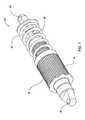
- a shock absorber of U.S. Pat. No. 7,293,764is shown herein as FIG. 1 .
- the shock absorber 10comprises a damper assembly 15 consisting of a chamber 18 housing a piston (not shown) and rod 20 and a helical spring 25 disposed on the damper in a manner whereby the spring and damper operate together.
- the shock absorberis attached via eyeholes 30 , 35 to separate portions of a vehicle (not shown) and the shock operates when there is relative movement between those portions.
- U.S. Pat. No. 5,044,614(“614 patent”) shows a damper body carrying a thread 42.
- a helical spring 18surrounds the damper body.
- the compression in the helical spring 18may be pre-set by means of a nut 48 and a lock nut 50.
- the nut 48may be translated axially relative to the body (“tube”) 16 and thread 42 by rotating the nut 48 around the threaded sleeve 42. Rotation of the nut 48 in a given direction (e.g.
- lock nut 50is rotated, using a wrench, up against nut 48 and tightened in a binding relation therewith.
- shock absorbersutilize gas as a spring medium in place of, or in addition to, mechanical springs.
- Gas spring type shock absorbershaving integral dampers, are described in U.S. Pat. Nos. 6,135,434, 6,360,857 and 6,311,962, each of which is herein incorporated in its entirety by reference.
- U.S. Pat. No. 6,360,857shows a shock absorber having selectively adjustable damping characteristics.
- U.S. Pat. No. 7,163,222which is incorporated herein in its entirety by reference, describes a gas sprung front shock absorber for a bicycle (a “fork”) having a selective “lock out” and adjustable “blow off” function.
- the spring mechanism (gas or mechanical) of some shock absorbersis adjustable so that it can be preset to varying initial states of compression.
- the shock spring (gas or mechanical)may comprise different stages having varying spring rates thereby giving the overall shock absorber a compound spring rate depending varying through the stroke length. In that way the shock absorber can be adjusted to accommodate heavier or lighter carried weight, or greater or lesser anticipated impact loads.
- shock absorbersare pre-adjusted to account for varying terrain and anticipated speeds and jumps. Shocks are also adjusted according to certain rider preferences (e.g. soft—firm).
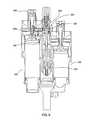
- FIG. 28A type of integrated spring/damper shock absorber, having a gas spring, is shown in FIG. 28, for example, of U.S. Pat. No. 7,374,028, which is incorporated herein in its entirety by reference.
- the shock shown in FIG. 28 of the '028 patentalso includes an “adjustable intensifier assembly 510 .” That intensifier or “reservoir” accepts damping fluid from chamber 170 as the fluid is displaced from that chamber by the incursion of rod 620 into chamber 170 during a compression stroke of the shock.
- the intensifier valve assemblyregulates flow of damping fluid into and out of the reservoir, and an embodiment of the valve assembly is shown in FIG. 17 of the patent.
- reservoir portions of dampersare separate components whereby a separate chamber is provided for fluid expelled from the main chamber.
- a damper with such a remote reservoiris illustrated in FIG. 9 of the '028 patent incorporated herein.
- Other suspension systemsuse multiple, separate reservoir-type chambers that divide the usable dampening capability of the shock. In these designs, fluid is pushed from the main dampening cylinder and with valving, the reservoir chambers are utilized in various ways. By using one or both chambers, the travel available in the shock can be determined by a user. Configurations of multiple reservoir-type shocks are shown in U.S. Pat. No. 7,219,881, which is incorporated herein in its entirety by reference. The presently available dual reservoir designs have drawbacks.
- the present inventiongenerally relates to a vehicle shock absorber comprising a main damper cylinder, a first reservoir and a second reservoir (although the principles herein may be extended to a third or more reservoirs as well).
- a first operational modeincludes a fluid path between the cylinder, optionally via a valve, and a first reservoir and then a path between the first and a second reservoir.
- a second operational modea fluid path is utilized between the cylinder, optionally via a valve, and one of the reservoirs, the path excluding the other reservoir. Operation between the modes is user selectable.
- FIG. 1is a perspective view of a shock absorber including a damper and a spring.
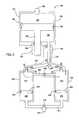
- FIG. 2is a schematic view of a damper with two reservoirs.
- FIG. 3is a section view of a Schrader-type valve.
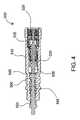
- FIG. 4is a section view of a Schrader-type valve.
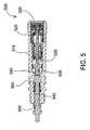
- FIG. 5is a section view of a Schrader-type valve.
- FIG. 6is a section view showing a damper cylinder with a valve adjacent thereto and fluid paths between the damper cylinder and valve.
- FIG. 7is a section view showing a valve and two reservoirs with fluid paths therebetween in a “full-travel” mode of the shock absorber.
- FIG. 8is a section view showing the valve and two reservoirs with fluid paths therebetween in a “half-travel” mode.
- FIG. 9is a section view showing a rebound pathway for fluid between the reservoirs.
- FIG. 2is a schematic view of a shock absorber embodiment 100 that utilizes a main damper 125 and two reservoir chambers or Internal Floating Piston chambers (IFPs) 300 , 400 .
- the shock embodiment of FIG. 2operates as a “pull shock”, which means the shock absorber gets pulled in tension to an extended condition as the suspension mechanism driving the shock reacts to compressive forces caused by terrain irregularities (bumps that compress the rear wheel toward the bicycle frame).
- terrain irregularitiesbump that compress the rear wheel toward the bicycle frame.
- a shock absorberextends or compresses in response to compressive terrain features is a function of the suspension linkage in which the shock is mounted.
- the oil chamber and gas chambers of the shockare in reversed placement relative to the main piston and shaft seal end of the main cylinder.
- a “push shock”on the other hand, the shock absorber gets pushed to a shorter condition as the suspension mechanism driving the shock accommodates compressive terrain irregularities.
- the principles of pull and push shocksremain substantially the same and the embodiments described and claimed herein are equally intended for both.
- a shock absorberis operatively mounted between an unsprung portion of a bicycle, such as the swing arm and rear axle, and a sprung portion of the bicycle such as the frame.
- a representative example embodiment of shock absorberderives from the shock absorber shown in FIG. 28 of, and elsewhere in, U.S. Pat. No. 7,374,028 which is incorporated herein by reference.
- the main damper 125has a piston 180 mounted on a shaft 185 .
- the piston 180is solid without the typical passages formed therethrough for the passage of fluid from one side of the piston 180 to the other side (although in some embodiments the piston may also included damping passages and valving).
- the shaft and piston assemblyis fitted into a main cylinder 178 .
- the cylinderis divided into a fluid (e.g. damping fluid, oil) chamber 188 and compressible fluid or gas (e.g. air, nitrogen) chamber 189 and this division is created by the solid piston, which seals on its OD with a seal such as an O-ring seal 190 .
- the shaft 185is also sealed where it extends a bulkhead of the main cylinder 178 with O-ring seal 186 .
- the air chamber 189 within the cylinderbecomes bigger (increases in volume) and the fluid chamber 188 within the cylinder becomes smaller. Fluid is pushed by the piston from the fluid chamber 188 , through a compression damping circuit that includes a valve 200 , and into one or both of the two IFP chambers 300 , 400 , as will be described herein.
- the first chamber 300 and second 400 IFP chambersare also each separated into a fluid chamber 301 , 401 and an gas (e.g. air) chamber 302 , 402 by a floating piston 305 , 405 of each chamber 300 , 400 .
- the floating pistonis sealed within the chamber by a suitable seal such as an O-ring seal 306 , 406 .
- a suitable sealsuch as an O-ring seal 306 , 406 .
- gas pressure in the gas chamber 189 of the main cylinder 178is adjustable using a fill valve 155 .
- Gas pressure in the IFPs 300 , 400is also user-adjustable.
- the gas volumes 302 , 402 of the IFPsare in fluid communication with a single fill valve 315 via a communication path 311 .
- another valve 500 adjacent the fill valve 315 , or integral therewith,is a Schrader-type valve for filling the first and second IFP air chambers 302 , 402 to an equal pressure and then subsequently maintaining isolation of chambers 302 and 402 one from the other during use.
- the Schrader valveincludes an axially movable stem member depressible to communicate with the first chamber through a first port and further depressible to communicate with the first and second chambers through a second port.
- a single volumecan be filled or preferably, both volumes, 302 , 402 can be filled to an equal pressure in a single action by the user.
- the first 302 and second 402 volumesare filled by introducing pressure, from a suitable gas pump or other source of pressurized gas, into the gas fill valve 315 which includes or operates with, or is replaced by, a Schrader-type valve 500 as shown in FIGS. 3-5 .
- the valve 500is designed to fill both of the first and second volumes with pressurized gas from the single valve body 510 .
- the valveis closed with no communication of air therethrough.
- a valve stem 520is connected through a valve core 525 to a primary fill valve 530 such that axial movement of the spring loaded valve stem 520 causes an opening of the primary fill valve 530 and axial movement of a valve pusher stem 535 .
- Sufficient axial movement of the valve pusher stem 535closes a gap 540 until the valve pusher stem 535 contacts the second chamber fill valve stem 545 .
- further movement of the valve pusher stem 535moves the second fill valve stem 545 and correspondingly separates the second fill valve 550 from a valve seat.
- the designensures that sufficient axial movement of the valve stem 520 opens the primary fill valve 530 and further movement of the valve stem subsequently opens the second fill valve 550 .
- FIG. 4illustrates a Schrader-type valve 500 with the valve stem 520 depressed and primary fill valve 530 open. In this position, pressurized air communicates through the valve 530 and to exit 560 formed in valve body 510 which preferably leads to the first gas volume 302 .
- FIG. 5illustrates the Schrader-type valve 500 with valve 530 open and gap 540 closed. Further, the second fill valve stem 545 has been axially depressed to open secondary fill valve 550 . With the components of the Schrader-type valve in the position shown in FIG. 5 , the first and second volumes 302 , 402 can be filled simultaneously. Gap 540 can be sized to determine operative characteristics of the valve 500 . For example, a gap of 0.050′′ in one embodiment leaves a gap of sufficient width that second chamber is not inadvertently filled along with the first chamber.
- the valve stem 520may be moved either mechanically, by a probe on a pressure fitting (not shown) of a pressurized gas source, or solely by the introduction of pressurized gas into the fill valve body 510 wherein the pressurized gas acts over the surface area (i.e. piston area) of the primary fill valve 530 .
- the dimension of the gap 540is set such that movement of the valve stem 520 and primary fill valve 530 , caused solely by the introduction of pressure, is not sufficient under normal operating pressures to close the gap 540 between the valve pusher stem 535 and the secondary fill valve stem 545 .
- only the primary fill valve 530is opened allowing pressurized gas to be introduced into the first volume 302 .
- Movement sufficient to close the gap 540 and open secondary fill valve 550may be induced by a gas fill fitting (not shown) connected to the fill gas pressure source and having a protrusion or “stinger” in it that is dimensioned to move the valve stem a sufficient distance to close the gap and open the secondary fill valve 550 .
- a fittingmay be used without a stinger and the valve stem 520 may be moved by gas pressure from the fill gas pressure source.
- the movement of the valve stemwill be insufficient to open the secondary chamber fill valve and only the first volume will be filled.
- the respective porting of the valve assemblycan be reversed (not shown) so that initial movement of the valve stem opens the second fill valve and further movement closes the gap and opens the primary fill valve.
- a mechanical probeattached to a pressure hose fitting (not shown) for example, is used to move the valve stem 520 .
- the length of the probeis sufficient to open the primary fill valve 530 , close the gap 540 , cause movement of the valve pusher stem 535 and secondary fill valve stem 545 and thereby open the secondary fill valve 550 .
- pressurized gasflows into the first volume 302 as previously described and also through the open secondary fill valve 350 , permitting flow into the second volume 402 .
- the IFP gas pressureacts as the shock absorber main spring in one embodiment tending to resist extension of the “pull” shock, thereby providing a spring function for the shock absorber 100
- the main cylinder air chamber 189acts as a shock absorber “negative spring” for the “pull” shock, tending to resist compression thereof and, by user adjustment, aiding in tailoring of gas spring curves by the user.
- the embodiment of FIG. 2is designed whereby gas pressure in IFP cylinders 300 , 400 will bias the piston 180 towards the closed end of the main cylinder 178 .
- valve 200permits operation of the shock absorber of FIG. 2 in three different settings: full-travel, half-travel and lock out.
- the systemis intended to be user-operable whereby the operator of the vehicle can shift the valve 200 between the three functions.
- the full-travel settingthe oil is pushed by the piston 180 from the main cylinder 178 and along a path that is shown on schematic FIG. 2 as 150 .
- the fluidextends through valve 200 to first IFP 300 and then, via a separate and direct communication path 160 , to IFP 400 .
- This settingmakes both IFP gas chambers (and volumes) 302 , 402 available as gas springs in operation of the shock absorber.
- the fluidis transferred, during both extension and compression of the shock, along a path that includes the damping fluid reservoirs in series. Because of that, all of the reservoir damping liquid is available during the full stroke of the shock absorber on every stroke. Damping fluid communication directly between reservoirs ensures that the reservoirs remain relatively equalized (or at a known and predetermined operational differential) during operation and are not subject to unplanned and detrimental fluid fill fluctuations. Additionally, the sequential operation permits any metering of fluid to be performed at a single location so that there is no need (although optionally there may still be) to meter the fluid separately in each IFP reservoir.
- a second compression setting(e.g. “half-travel mode”), shown by path 151 of FIG. 2 , oil flow to the first IFP chamber 300 is blocked at valve 200 , causing all the pushed oil to flow into the second IFP chamber 400 and therefore changing the effective spring rate of the system (increasing the spring rate by decreasing the available IFP gas volume but therefore decreasing the available shock travel).
- the practical result of this half-travel settingis a stiffer-acting shock absorber.
- a third compression settingincludes the full closure of valve 200 , effectively blocking oil flow to both IFP chambers 300 , 400 and resulting in a shock absorber that is hydraulically locked out.
- the third settingis especially useful to prevent operation of the shock absorber in conditions when its operation is unnecessary or unwanted by a user.
- the valve 200may include a “blow off” or pressure relief feature (optionally user adjustable) so that even when “locked out” the shock absorber may move in response to overpressure thereby avoiding damage to the shock or vehicle or user.
- the three compression settings describedare selectable via user-accessible controls mounted adjacent components of the shock absorber 100 or remotely (with appropriate signal communication to the shock absorber such as cable, wire, or wireless with servo motors).
- a knobis adjustable between three positions corresponding to the full-travel, half-travel and lock out modes/positions described herein.
- the shock absorber of the embodiment describedalso permits adjustment of operation in a rebound stroke (e.g. adjustment of rebound damping).
- the IFP gas pressure in 302 , 402pushes fluid out of the IFP chambers 300 , 400 and back into the main cylinder fluid chamber 188 as the piston 180 is moved in a rebound direction (shown as arrow 153 ).
- Each IFPhas an externally adjustable valve 303 , 403 that allows the rebound flowing fluid to be metered, resulting in different rebound fluid flow speeds.
- the rebound fluidis divided between the adjustable valves and factory set shims (not shown).
- the valves 303 , 403permit a user to change the operational aspects of the IFPs for proper suspension depending on, among other things, road/trail conditions and loads.
- both IFP cylinder oil chambers 301 , 401flow their rebound flow oil back to the main cylinder 178 through one common rebound adjustor valve and flow path.
- all rebound fluidtravels through and can be adjusted at valve 303 of IFP 300 .
- half-travel modeall fluid travels back towards the main damper 125 via valve 403 of IFP 400 .
- the movement of oil flow out of the main cylinder oil chamber 188 (compression flow shown as arrow 152 ) and oil back into the main cylinder oil chamber 188 (rebound flow 153 )will be elaborated upon by example.
- the first compression settingfull-travel mode
- oilwill flow into the first IFP 300 .
- the full-travel mode flow path 150comprises nodes 1 - 5 of FIG. 2 .
- the IFP oil chambers 301 , 401will communicate with one another via fluid path 160 (nodes 4 - 5 including valve 322 ) connecting them.
- This fluid pathincludes valve 322 that allows flow to communicate in both directions between the IFP oil chambers 300 , 400 when the shock is set in this first, full-travel compression setting.
- the compression damping and the rebound damping in the full-travel compression settingwill each be unique to this setting as the compression oil flow and rebound oil flow are directed into and out of only one of the IFP chambers (IFP 300 via node 3 ) upstream of the fluid path 320 that permits both IFP chambers to communicate.
- a rebound adjustor valve 303provided in path 3 - 2 controls and adjusts the rebound flow for this full-travel setting. Shimmed or valved (shims being an example valve type) compression and shimmed or valved rebound damping (not shown) are also provided in path 3 - 2 specifically for the full-travel setting.
- compression flowis directed to second IFP 400 along path 151 as shown in FIG. 2 .
- Valve 322 in fluid path 160is closed in this setting in the direction of IFP 400 to 300 .
- a low speed rebound adjustor 403is provided in path 151 to control low speed rebound damping for this second compression setting condition, and distinct shimmed compression damping (not shown) and rebound damping are provided in path 151 specifically for this second, half-travel setting.
- Compression flowis now directed only into IFP 400 and rebound flow is supplied only from IFP 400 . While the operation is described utilizing the IFPs 300 , 400 in a particular manner it will be understood that the chambers 300 , 400 could be reversed in function and sequencing.
- the described embodimentprovides half or full-travel operation and in each case, the rebound flow of fluid moves in a single path and is metered at a single location, thus avoiding a problem of prior art arrangements that leads one IFP crashing because it receives less fluid than it expels due to unequal metering.
- FIGS. 6-9are section views showing portions of a suspension system that include some of the embodiments described herein.
- FIGS. 6-7for example illustrate the flow of fluid within the shock in full-travel mode whereby both of the IFPs 300 , 400 are utilized in the operation.
- FIG. 8illustrates fluid flow in half-travel mode, wherein only one of the IFPs ( 400 ) is utilized.
- FIG. 6shows the path of fluid between the main damper 125 and valve 200 , which in the case of FIG. 6 , is a spool valve (e.g. in one embodiment a single valve member having multiple functions) with a central shaft 205 for directing fluid in a variety of different directions depending upon the axial location of the shaft 205 relative to the valve body and ports 220 , 225 ( FIG. 7 ) connecting the valve to the IFPs 300 , 400 .
- a port 201is visible for providing fluid communication between the main damper 125 and valve 200 .
- fluid travel in a compression mode of the damperis shown by a solid line/arrow 230 while fluid travel in the rebound mode is shown by a dotted line/arrow 235 .
- solid line 230illustrates the path of fluid during a compression stroke as fluid leaves the damper 125 and moves into the valve 200 from which it will travel to both IFPs 300 , 400 .
- FIG. 7corresponds to FIG. 6 and shows fluid travel 230 from a port 220 in the spool valve 200 directly to a first IFP 300 .
- a separate path 230 ais utilized to carry fluid from IFP 300 to IFP 400 through path 160 which in the embodiment of FIG. 7 , is included in spool valve 200 .
- valve 322controlling fluid flow in flow path 320 ( FIG. 2 ) is also incorporated into the spool valve 200 and the path of fluid through that path is determined by a setting of the valve.
- a portion of the fluid 235 a traveling out of (rebounding) IFP 300can be metered by rebound needle valve 303 ( FIG. 2 ) that is adjustable by a user via adjustment knob 255 accessible at an upper end of the IFP 300 .
- Another portion of the rebound fluid 235is metered by shims (not shown).
- FIG. 8is a section view of the spool valve 200 and the IPOs 300 , 400 and illustrates the half-travel mode when only a single IFP 400 is utilized by the system.
- fluidtravel between the valve and IFP 400 while IF 300 is not utilized.
- the half-travel modeonly the gas spring portion of one IFP 400 is used and the system therefore operates with stiffer characteristics.
- the rebound path of the fluid(dotted line 235 ) wherein a portion of the fluid travels through another needle-type valve 403 ( FIG. 2 ) that is adjustable via knob 256 , thereby permitting the rebound characteristics of the shock to be user-adjusted in the half-travel mode.
- FIG. 9is another section view showing both IFPs and the previously discussed fluid path between them (valve C) having a one-way characteristic in which fluid may travel from IFP 300 to IFP 400 in half-travel mode of operation.
- the featurepermits fluid in a non-used IFP to move to the other IFP so it can be utilized in operation of the shock absorber.
- a shock absorber using one or more of multiple IFPsto provide differing and adjustable amounts of a spring function when the shock absorber operates.
- one modeprovides that two IFPs are used in a sequential manner whereby the fluid travels a path between them from one to the next.
- the fluidtravels back along the same or similar path, thereby providing a single point of metering and avoiding some drawbacks of earlier designs, most notably the possibility of an IFP locking up due to expulsion of all of its fluid due to differing amounts of metering of the rebound fluid.
- the flow path between reservoirsincludes a one way flowing check valve disposed to check fluid flow entering the reservoir unused during half travel mode but allowing fluid to flow from that cylinder to the half travel damping reservoir. In that way, any fluid trapped in the unselected cylinder while changing from full travel to half travel can freely flow back to the main cylinder, or otherwise into the selected damping circuit, as needed but no new fluid will be introduced into the unselected reservoir during half travel operation. It is noteworthy that several other flow options and combinations are available in the shown embodiments.
Landscapes
- Engineering & Computer Science (AREA)
- General Engineering & Computer Science (AREA)
- Mechanical Engineering (AREA)
- Axle Suspensions And Sidecars For Cycles (AREA)
- Fluid-Damping Devices (AREA)
Abstract
Description
Claims (14)
Priority Applications (6)
| Application Number | Priority Date | Filing Date | Title |
|---|---|---|---|
| US12/794,219US8807542B2 (en) | 2009-06-05 | 2010-06-04 | Apparatus and methods for a vehicle shock absorber |
| US14/330,850US9255620B2 (en) | 2009-06-05 | 2014-07-14 | Apparatus and methods for a vehicle shock absorber |
| US14/993,861US9816578B2 (en) | 2009-06-05 | 2016-01-12 | Apparatus and methods for a vehicle shock absorber |
| US15/808,645US10240655B2 (en) | 2009-06-05 | 2017-11-09 | Apparatus and methods for a vehicle shock absorber |
| US16/361,954US10704640B2 (en) | 2009-06-05 | 2019-03-22 | Apparatus and methods for a vehicle shock absorber |
| US16/910,730US20200318705A1 (en) | 2009-06-05 | 2020-06-24 | Apparatus and methods for a vehicle shock absorber |
Applications Claiming Priority (2)
| Application Number | Priority Date | Filing Date | Title |
|---|---|---|---|
| US18476309P | 2009-06-05 | 2009-06-05 | |
| US12/794,219US8807542B2 (en) | 2009-06-05 | 2010-06-04 | Apparatus and methods for a vehicle shock absorber |
Related Child Applications (1)
| Application Number | Title | Priority Date | Filing Date |
|---|---|---|---|
| US14/330,850ContinuationUS9255620B2 (en) | 2009-06-05 | 2014-07-14 | Apparatus and methods for a vehicle shock absorber |
Publications (2)
| Publication Number | Publication Date |
|---|---|
| US20100308516A1 US20100308516A1 (en) | 2010-12-09 |
| US8807542B2true US8807542B2 (en) | 2014-08-19 |
Family
ID=42731826
Family Applications (6)
| Application Number | Title | Priority Date | Filing Date |
|---|---|---|---|
| US12/794,219Active2031-04-02US8807542B2 (en) | 2009-06-05 | 2010-06-04 | Apparatus and methods for a vehicle shock absorber |
| US14/330,850ActiveUS9255620B2 (en) | 2009-06-05 | 2014-07-14 | Apparatus and methods for a vehicle shock absorber |
| US14/993,861ActiveUS9816578B2 (en) | 2009-06-05 | 2016-01-12 | Apparatus and methods for a vehicle shock absorber |
| US15/808,645ActiveUS10240655B2 (en) | 2009-06-05 | 2017-11-09 | Apparatus and methods for a vehicle shock absorber |
| US16/361,954ActiveUS10704640B2 (en) | 2009-06-05 | 2019-03-22 | Apparatus and methods for a vehicle shock absorber |
| US16/910,730AbandonedUS20200318705A1 (en) | 2009-06-05 | 2020-06-24 | Apparatus and methods for a vehicle shock absorber |
Family Applications After (5)
| Application Number | Title | Priority Date | Filing Date |
|---|---|---|---|
| US14/330,850ActiveUS9255620B2 (en) | 2009-06-05 | 2014-07-14 | Apparatus and methods for a vehicle shock absorber |
| US14/993,861ActiveUS9816578B2 (en) | 2009-06-05 | 2016-01-12 | Apparatus and methods for a vehicle shock absorber |
| US15/808,645ActiveUS10240655B2 (en) | 2009-06-05 | 2017-11-09 | Apparatus and methods for a vehicle shock absorber |
| US16/361,954ActiveUS10704640B2 (en) | 2009-06-05 | 2019-03-22 | Apparatus and methods for a vehicle shock absorber |
| US16/910,730AbandonedUS20200318705A1 (en) | 2009-06-05 | 2020-06-24 | Apparatus and methods for a vehicle shock absorber |
Country Status (2)
| Country | Link |
|---|---|
| US (6) | US8807542B2 (en) |
| EP (1) | EP2258961B1 (en) |
Cited By (14)
| Publication number | Priority date | Publication date | Assignee | Title |
|---|---|---|---|---|
| US20130168194A1 (en)* | 2011-12-29 | 2013-07-04 | Fox Factory, Inc. | Dampers with thermal expansion compensation |
| US20160069415A1 (en)* | 2014-09-09 | 2016-03-10 | Push Industries, Incorporated | Control valve to permit adjustability of a shock absorber |
| US20160159184A1 (en)* | 2014-12-03 | 2016-06-09 | Icon Vehicle Dynamics, LLC | Shock absorbers |
| US20170321781A1 (en)* | 2014-11-13 | 2017-11-09 | öHLINS RACING AB | Flow adjusting device |
| US9816578B2 (en) | 2009-06-05 | 2017-11-14 | Fox Factory, Inc. | Apparatus and methods for a vehicle shock absorber |
| US20190100071A1 (en)* | 2017-09-29 | 2019-04-04 | Fox Factory, Inc. | Electronically controlled sway bar damping link |
| USD872837S1 (en)* | 2017-08-28 | 2020-01-14 | Qa1 Precision Products, Inc. | Bleed needle |
| US11085502B2 (en) | 2017-08-28 | 2021-08-10 | Qa1 Precision Products, Inc. | Bleed needle for a hydraulic system |
| US20220118814A1 (en)* | 2019-08-01 | 2022-04-21 | Audi Ag | Spring damper apparatus for a vehicle, in particular for a motor vehicle, and vehicle having at least one such spring damper apparatus |
| US11634003B2 (en) | 2020-12-17 | 2023-04-25 | Fox Factory, Inc. | Automated control system for an electronically controlled sway bar link |
| EP4048537A4 (en)* | 2019-10-22 | 2023-11-22 | Fox Factory, Inc. | HYDRAULIC ANTI ROLL BAR COUPLING |
| US12083850B2 (en) | 2021-12-20 | 2024-09-10 | Fox Factory, Inc. | Electronically controlled sway bar damping link |
| US12270062B2 (en) | 2017-09-08 | 2025-04-08 | Fox Factory, Inc. | Electronically controlled sway bar damping link |
| US12311720B2 (en) | 2022-02-23 | 2025-05-27 | Fox Factory, Inc. | Hydraulic cross-linked suspension |
Families Citing this family (29)
| Publication number | Priority date | Publication date | Assignee | Title |
|---|---|---|---|---|
| US20100170760A1 (en) | 2009-01-07 | 2010-07-08 | John Marking | Remotely Operated Bypass for a Suspension Damper |
| US9452654B2 (en) | 2009-01-07 | 2016-09-27 | Fox Factory, Inc. | Method and apparatus for an adjustable damper |
| US10036443B2 (en) | 2009-03-19 | 2018-07-31 | Fox Factory, Inc. | Methods and apparatus for suspension adjustment |
| US9140325B2 (en) | 2009-03-19 | 2015-09-22 | Fox Factory, Inc. | Methods and apparatus for selective spring pre-load adjustment |
| US9422018B2 (en) | 2008-11-25 | 2016-08-23 | Fox Factory, Inc. | Seat post |
| US9038791B2 (en) | 2009-01-07 | 2015-05-26 | Fox Factory, Inc. | Compression isolator for a suspension damper |
| US11299233B2 (en) | 2009-01-07 | 2022-04-12 | Fox Factory, Inc. | Method and apparatus for an adjustable damper |
| US8936139B2 (en) | 2009-03-19 | 2015-01-20 | Fox Factory, Inc. | Methods and apparatus for suspension adjustment |
| EP2312180B1 (en) | 2009-10-13 | 2019-09-18 | Fox Factory, Inc. | Apparatus for controlling a fluid damper |
| US9162573B2 (en) | 2010-06-03 | 2015-10-20 | Polaris Industries Inc. | Electronic throttle control |
| US10330171B2 (en) | 2012-05-10 | 2019-06-25 | Fox Factory, Inc. | Method and apparatus for an adjustable damper |
| US9205717B2 (en) | 2012-11-07 | 2015-12-08 | Polaris Industries Inc. | Vehicle having suspension with continuous damping control |
| US8991840B2 (en)* | 2013-03-14 | 2015-03-31 | Oshkosh Defense, Llc | Load dependent damper for a vehicle suspension system |
| US10648554B2 (en) | 2014-09-02 | 2020-05-12 | Polaris Industries Inc. | Continuously variable transmission |
| US10183539B2 (en) | 2014-09-17 | 2019-01-22 | Fox Factory, Inc. | Shock absorber |
| CN107406094B (en) | 2014-10-31 | 2020-04-14 | 北极星工业有限公司 | System and method for controlling a vehicle |
| WO2017177174A1 (en) | 2016-04-08 | 2017-10-12 | Oshkosh Corporation | Leveling system for lift device |
| US10214071B1 (en) | 2016-05-28 | 2019-02-26 | PAL Suspension LLC | Vehicle suspension system with multi-stage hydraulic cylinder assemblies and external spring packs |
| CN110121438B (en) | 2016-11-18 | 2023-01-31 | 北极星工业有限公司 | vehicles with adjustable suspension |
| US10406884B2 (en) | 2017-06-09 | 2019-09-10 | Polaris Industries Inc. | Adjustable vehicle suspension system |
| US11012950B2 (en) | 2017-09-28 | 2021-05-18 | Sony Corporation | Base station and user equipment |
| DE102017218905B4 (en)* | 2017-10-24 | 2023-11-30 | Bayerische Motoren Werke Aktiengesellschaft | Spring-damper system with variable spring rate |
| WO2019183051A1 (en) | 2018-03-19 | 2019-09-26 | Polaris Industries Inc. | Continuously variable transmission |
| EP3810956A4 (en) | 2018-06-20 | 2022-07-13 | N10Z Performance Shocks LLC | Shock absorber assembly |
| US10987987B2 (en) | 2018-11-21 | 2021-04-27 | Polaris Industries Inc. | Vehicle having adjustable compression and rebound damping |
| US10737545B1 (en) | 2019-12-19 | 2020-08-11 | PAL Suspension LLC | Vehicle suspension system with multi-stage hydraulic cylinder assemblies and external spring packs |
| US12397878B2 (en) | 2020-05-20 | 2025-08-26 | Polaris Industries Inc. | Systems and methods of adjustable suspensions for off-road recreational vehicles |
| MX2022015902A (en) | 2020-07-17 | 2023-01-24 | Polaris Inc | Adjustable suspensions and vehicle operation for off-road recreational vehicles. |
| US20230027763A1 (en)* | 2021-07-21 | 2023-01-26 | Fox Factory, Inc. | Internal floating piston |
Citations (6)
| Publication number | Priority date | Publication date | Assignee | Title |
|---|---|---|---|---|
| US2974946A (en)* | 1957-01-17 | 1961-03-14 | Tuczek Franz Emil | Pneumatic spring structures |
| US3527452A (en)* | 1966-10-08 | 1970-09-08 | Rheinstahl Henschel Ag | Connecting device for a hydropneumatic spring member having an additional gas bubble |
| US4478431A (en)* | 1980-11-25 | 1984-10-23 | Bayerische Motoren Werke Aktiengesellschaft | Suspension system for vehicles |
| JPS6121814A (en)* | 1984-07-09 | 1986-01-30 | Kayaba Ind Co Ltd | Pressure regulator of gas spring |
| US5016909A (en)* | 1990-05-17 | 1991-05-21 | Lin Chien Hung | Automobile suspension system |
| US20050012255A1 (en)* | 2002-08-28 | 2005-01-20 | Peter Denk | Shock absorber |
Family Cites Families (22)
| Publication number | Priority date | Publication date | Assignee | Title |
|---|---|---|---|---|
| NL236456A (en)* | 1959-02-24 | |||
| DE1227785B (en)* | 1962-09-13 | 1966-10-27 | Boge Gmbh | Sealing arrangement in the working piston of level-regulating, hydropneumatic suspension struts for motor vehicles |
| US3499639A (en)* | 1966-04-27 | 1970-03-10 | Saviem | Hydropneumatic suspension systems of vehicles |
| JPS5169766A (en)* | 1974-12-12 | 1976-06-16 | Yamaha Motor Co Ltd | |
| JPS6121814Y2 (en) | 1981-02-02 | 1986-06-30 | ||
| JPS60193708A (en)* | 1984-03-15 | 1985-10-02 | Mazda Motor Corp | Hydropneumatic suspension |
| DE3414257C2 (en)* | 1984-04-14 | 1993-12-02 | Bosch Gmbh Robert | Spring element with variable hardness for vehicles |
| IT1224038B (en)* | 1988-12-28 | 1990-09-26 | Iveco Fiat | HYDROPNEUMATIC MAST PARTICULARLY FOR SUSPENSIONS OF VEHICLES SUCH AS INDUSTRIAL VEHICLES |
| US5044614A (en) | 1990-02-22 | 1991-09-03 | Rau John A | Shock absorber spring adjuster |
| US5553836A (en) | 1995-05-11 | 1996-09-10 | Patentials Incorporated | Adjustable suspension system |
| US5803443A (en) | 1997-09-24 | 1998-09-08 | Chang; Wu-Sung | Shock absorber for motor vehicles |
| US6311962B1 (en) | 1998-02-03 | 2001-11-06 | Fox Factory, Inc. | Shock absorber with external air cylinder spring |
| US6135434A (en) | 1998-02-03 | 2000-10-24 | Fox Factory, Inc. | Shock absorber with positive and negative gas spring chambers |
| US6360857B1 (en) | 1999-03-19 | 2002-03-26 | Fox Factory, Inc. | Damping adjuster for shock absorber |
| US6592136B2 (en) | 2001-07-02 | 2003-07-15 | Fox Factory, Inc. | Bicycle fork cartridge assembly |
| WO2003102425A2 (en)* | 2002-05-29 | 2003-12-11 | Progressive Suspension, Inc. | Hydraulic dampers with pressure regulated control valve and remote pressure adjustment |
| US7374028B2 (en) | 2003-07-08 | 2008-05-20 | Fox Factory, Inc. | Damper with pressure-sensitive compression damping |
| JP2006088754A (en)* | 2004-09-21 | 2006-04-06 | Toyota Motor Corp | Suspension device |
| US7690666B2 (en)* | 2005-08-18 | 2010-04-06 | Specialized Bicycle Components, Inc. | Position sensitive shock absorber |
| US7293764B2 (en) | 2006-02-03 | 2007-11-13 | Neotek Co., Ltd. | Adjusting mechanism with a helical spring of large diameter |
| US8894050B2 (en) | 2008-03-19 | 2014-11-25 | Fox Factory, Inc. | Methods and apparatus for suspending vehicles |
| US8807542B2 (en) | 2009-06-05 | 2014-08-19 | Fox Factory, Inc. | Apparatus and methods for a vehicle shock absorber |
- 2010
- 2010-06-04USUS12/794,219patent/US8807542B2/enactiveActive
- 2010-06-07EPEP10165114.9Apatent/EP2258961B1/enactiveActive
- 2014
- 2014-07-14USUS14/330,850patent/US9255620B2/enactiveActive
- 2016
- 2016-01-12USUS14/993,861patent/US9816578B2/enactiveActive
- 2017
- 2017-11-09USUS15/808,645patent/US10240655B2/enactiveActive
- 2019
- 2019-03-22USUS16/361,954patent/US10704640B2/enactiveActive
- 2020
- 2020-06-24USUS16/910,730patent/US20200318705A1/ennot_activeAbandoned
Patent Citations (6)
| Publication number | Priority date | Publication date | Assignee | Title |
|---|---|---|---|---|
| US2974946A (en)* | 1957-01-17 | 1961-03-14 | Tuczek Franz Emil | Pneumatic spring structures |
| US3527452A (en)* | 1966-10-08 | 1970-09-08 | Rheinstahl Henschel Ag | Connecting device for a hydropneumatic spring member having an additional gas bubble |
| US4478431A (en)* | 1980-11-25 | 1984-10-23 | Bayerische Motoren Werke Aktiengesellschaft | Suspension system for vehicles |
| JPS6121814A (en)* | 1984-07-09 | 1986-01-30 | Kayaba Ind Co Ltd | Pressure regulator of gas spring |
| US5016909A (en)* | 1990-05-17 | 1991-05-21 | Lin Chien Hung | Automobile suspension system |
| US20050012255A1 (en)* | 2002-08-28 | 2005-01-20 | Peter Denk | Shock absorber |
Cited By (26)
| Publication number | Priority date | Publication date | Assignee | Title |
|---|---|---|---|---|
| US10704640B2 (en) | 2009-06-05 | 2020-07-07 | Fox Factory, Inc. | Apparatus and methods for a vehicle shock absorber |
| US10240655B2 (en) | 2009-06-05 | 2019-03-26 | Fox Factory, Inc. | Apparatus and methods for a vehicle shock absorber |
| US9816578B2 (en) | 2009-06-05 | 2017-11-14 | Fox Factory, Inc. | Apparatus and methods for a vehicle shock absorber |
| US8950558B2 (en)* | 2011-12-29 | 2015-02-10 | Fox Factory, Inc. | Dampers with thermal expansion compensation |
| US20130168194A1 (en)* | 2011-12-29 | 2013-07-04 | Fox Factory, Inc. | Dampers with thermal expansion compensation |
| US10156280B2 (en)* | 2014-09-09 | 2018-12-18 | Push Industries, Incorporated | Control valve to permit adjustability of a shock absorber |
| US20160069415A1 (en)* | 2014-09-09 | 2016-03-10 | Push Industries, Incorporated | Control valve to permit adjustability of a shock absorber |
| US10584760B2 (en)* | 2014-11-13 | 2020-03-10 | öHLINS RACING AB | Flow adjusting device |
| US20170321781A1 (en)* | 2014-11-13 | 2017-11-09 | öHLINS RACING AB | Flow adjusting device |
| US10625555B2 (en) | 2014-12-03 | 2020-04-21 | Icon Vehicle Dynamics Llc | Shock absorbers |
| US10035396B2 (en) | 2014-12-03 | 2018-07-31 | Icon Vehicle Dynamics Llc | Shock absorbers |
| US20160159184A1 (en)* | 2014-12-03 | 2016-06-09 | Icon Vehicle Dynamics, LLC | Shock absorbers |
| US9610819B2 (en)* | 2014-12-03 | 2017-04-04 | Icon Vehicle Dynamics Llc | Shock absorbers |
| US11085502B2 (en) | 2017-08-28 | 2021-08-10 | Qa1 Precision Products, Inc. | Bleed needle for a hydraulic system |
| USD872837S1 (en)* | 2017-08-28 | 2020-01-14 | Qa1 Precision Products, Inc. | Bleed needle |
| US12270062B2 (en) | 2017-09-08 | 2025-04-08 | Fox Factory, Inc. | Electronically controlled sway bar damping link |
| US10981429B2 (en)* | 2017-09-29 | 2021-04-20 | Fox Factory, Inc. | Electronically controlled sway bar damping link |
| US20190100071A1 (en)* | 2017-09-29 | 2019-04-04 | Fox Factory, Inc. | Electronically controlled sway bar damping link |
| US11926189B2 (en) | 2017-09-29 | 2024-03-12 | Fox Factory, Inc. | Electronically controlled sway bar damping link |
| US20220118814A1 (en)* | 2019-08-01 | 2022-04-21 | Audi Ag | Spring damper apparatus for a vehicle, in particular for a motor vehicle, and vehicle having at least one such spring damper apparatus |
| US11833877B2 (en)* | 2019-08-01 | 2023-12-05 | Audi Ag | Spring damper apparatus for a vehicle, in particular for a motor vehicle, and vehicle having at least one such spring damper apparatus |
| EP4048537A4 (en)* | 2019-10-22 | 2023-11-22 | Fox Factory, Inc. | HYDRAULIC ANTI ROLL BAR COUPLING |
| US11634003B2 (en) | 2020-12-17 | 2023-04-25 | Fox Factory, Inc. | Automated control system for an electronically controlled sway bar link |
| US12263711B2 (en) | 2020-12-17 | 2025-04-01 | Fox Factory, Inc. | Automated control system for an electronically controlled sway bar link |
| US12083850B2 (en) | 2021-12-20 | 2024-09-10 | Fox Factory, Inc. | Electronically controlled sway bar damping link |
| US12311720B2 (en) | 2022-02-23 | 2025-05-27 | Fox Factory, Inc. | Hydraulic cross-linked suspension |
Also Published As
| Publication number | Publication date |
|---|---|
| US10704640B2 (en) | 2020-07-07 |
| US10240655B2 (en) | 2019-03-26 |
| EP2258961B1 (en) | 2021-05-12 |
| US20160123424A1 (en) | 2016-05-05 |
| EP2258961A2 (en) | 2010-12-08 |
| US20200318705A1 (en) | 2020-10-08 |
| US20190219122A1 (en) | 2019-07-18 |
| US9816578B2 (en) | 2017-11-14 |
| US20150014106A1 (en) | 2015-01-15 |
| EP2258961A3 (en) | 2017-10-11 |
| US20100308516A1 (en) | 2010-12-09 |
| US9255620B2 (en) | 2016-02-09 |
| US20180066724A1 (en) | 2018-03-08 |
Similar Documents
| Publication | Publication Date | Title |
|---|---|---|
| US10704640B2 (en) | Apparatus and methods for a vehicle shock absorber | |
| US10556477B2 (en) | Suspension damper with by-pass valves | |
| US5934422A (en) | Step motor actuated continuously variable shock absorber | |
| CN108626294B (en) | Vehicle shock absorber and control method thereof | |
| US7673726B2 (en) | Bicycle damping enhancement system | |
| US6883650B2 (en) | Adjustable shock absorber | |
| JP4976855B2 (en) | Solenoid-driven continuously variable servo valve for damping adjustment in shock absorbers and struts | |
| US11370261B2 (en) | Methods and apparatus for suspending vehicles | |
| JP2950594B2 (en) | Shock absorber including valve for hydraulic fluid | |
| CN113498396B (en) | Buffer device | |
| US11040754B2 (en) | Dampers for bicycle suspension components | |
| US11760150B2 (en) | Suspension damper with by-pass valves | |
| US20240391287A1 (en) | Adjustable bypass shock absorber | |
| JPH0996336A (en) | Damping force adjustable hydraulic shock absorber | |
| JPH10157435A (en) | Spring force changing device | |
| JPH05248478A (en) | Adjustable damping force shock absorber |
Legal Events
| Date | Code | Title | Description |
|---|---|---|---|
| AS | Assignment | Owner name:FOX FACTORY, INC., CALIFORNIA Free format text:ASSIGNMENT OF ASSIGNORS INTEREST;ASSIGNORS:GALASSO, MARIO;WOOTTEN, DENNIS K.;ANDERSON, BRYAN WESLEY;SIGNING DATES FROM 20100720 TO 20100802;REEL/FRAME:024800/0575 | |
| AS | Assignment | Owner name:COMPASS GROUP DIVERSIFIED HOLDINGS LLC, CONNECTICU Free format text:FIRST AMENDMENT TO INTELLECTUAL PROPERTY SECURITY AGREEMENT;ASSIGNOR:FOX FACTORY, INC.;REEL/FRAME:027124/0088 Effective date:20111025 | |
| AS | Assignment | Owner name:FOX FACTORY, INC., CALIFORNIA Free format text:RELEASE BY SECURED PARTY;ASSIGNOR:COMPASS DIVERSIFIED HOLDINGS LLC;REEL/FRAME:031007/0958 Effective date:20130813 | |
| AS | Assignment | Owner name:SUNTRUST BANK, AS ADMINISTRATIVE AGENT, GEORGIA Free format text:SECURITY AGREEMENT;ASSIGNOR:FOX FACTORY, INC.;REEL/FRAME:031015/0255 Effective date:20130813 | |
| AS | Assignment | Owner name:FOX FACTORY, INC., CALIFORNIA Free format text:CORRECTIVE ASSIGNMENT TO CORRECT THE ASSIGNOR'S NAME PREVIOUSLY RECORDED ON REEL 031007 FRAME 0958. ASSIGNOR(S) HEREBY CONFIRMS THE RELEASE OF TRADEMARK SECURITY INTEREST;ASSIGNOR:COMPASS GROUP DIVERSIFIED HOLDINGS LLC;REEL/FRAME:031059/0649 Effective date:20130813 | |
| STCF | Information on status: patent grant | Free format text:PATENTED CASE | |
| MAFP | Maintenance fee payment | Free format text:PAYMENT OF MAINTENANCE FEE, 4TH YEAR, LARGE ENTITY (ORIGINAL EVENT CODE: M1551) Year of fee payment:4 | |
| AS | Assignment | Owner name:FOX FACTORY, INC., GEORGIA Free format text:RELEASE OF PATENT SECURITY INTEREST;ASSIGNOR:SUNTRUST BANK, AS ADMINISTRATIVE AGENT;REEL/FRAME:049371/0573 Effective date:20190603 | |
| AS | Assignment | Owner name:BANK OF AMERICA, N.A., AS ADMINISTRATIVE AGENT, CA Free format text:PATENT SECURITY AGREEMENT;ASSIGNOR:FOX FACTORY, INC.;REEL/FRAME:049388/0585 Effective date:20190603 Owner name:BANK OF AMERICA, N.A., AS ADMINISTRATIVE AGENT, CALIFORNIA Free format text:PATENT SECURITY AGREEMENT;ASSIGNOR:FOX FACTORY, INC.;REEL/FRAME:049388/0585 Effective date:20190603 | |
| MAFP | Maintenance fee payment | Free format text:PAYMENT OF MAINTENANCE FEE, 8TH YEAR, LARGE ENTITY (ORIGINAL EVENT CODE: M1552); ENTITY STATUS OF PATENT OWNER: LARGE ENTITY Year of fee payment:8 | |
| AS | Assignment | Owner name:WELLS FARGO BANK, NATIONAL ASSOCIATION, NORTH CAROLINA Free format text:SECURITY INTEREST;ASSIGNOR:FOX FACTORY, INC.;REEL/FRAME:059616/0435 Effective date:20220405 | |
| AS | Assignment | Owner name:FOX FACTORY, INC., GEORGIA Free format text:RELEASE BY SECURED PARTY;ASSIGNOR:BANK OF AMERICA, N.A.;REEL/FRAME:059704/0224 Effective date:20220405 |