US8807435B2 - Decoding multi-resolution optical codes - Google Patents
Decoding multi-resolution optical codesDownload PDFInfo
- Publication number
- US8807435B2 US8807435B2US13/080,846US201113080846AUS8807435B2US 8807435 B2US8807435 B2US 8807435B2US 201113080846 AUS201113080846 AUS 201113080846AUS 8807435 B2US8807435 B2US 8807435B2
- Authority
- US
- United States
- Prior art keywords
- code
- image
- information
- elements
- processor
- Prior art date
- Legal status (The legal status is an assumption and is not a legal conclusion. Google has not performed a legal analysis and makes no representation as to the accuracy of the status listed.)
- Expired - Fee Related, expires
Links
Images


Classifications
- G—PHYSICS
- G06—COMPUTING OR CALCULATING; COUNTING
- G06K—GRAPHICAL DATA READING; PRESENTATION OF DATA; RECORD CARRIERS; HANDLING RECORD CARRIERS
- G06K7/00—Methods or arrangements for sensing record carriers, e.g. for reading patterns
- G06K7/10—Methods or arrangements for sensing record carriers, e.g. for reading patterns by electromagnetic radiation, e.g. optical sensing; by corpuscular radiation
- G06K7/14—Methods or arrangements for sensing record carriers, e.g. for reading patterns by electromagnetic radiation, e.g. optical sensing; by corpuscular radiation using light without selection of wavelength, e.g. sensing reflected white light
- G06K7/1404—Methods for optical code recognition
- G06K7/1408—Methods for optical code recognition the method being specifically adapted for the type of code
- G06K7/1434—Barcodes with supplemental or add-on codes
- G—PHYSICS
- G06—COMPUTING OR CALCULATING; COUNTING
- G06K—GRAPHICAL DATA READING; PRESENTATION OF DATA; RECORD CARRIERS; HANDLING RECORD CARRIERS
- G06K19/00—Record carriers for use with machines and with at least a part designed to carry digital markings
- G06K19/06—Record carriers for use with machines and with at least a part designed to carry digital markings characterised by the kind of the digital marking, e.g. shape, nature, code
- G06K19/06009—Record carriers for use with machines and with at least a part designed to carry digital markings characterised by the kind of the digital marking, e.g. shape, nature, code with optically detectable marking
- G06K19/06046—Constructional details
- G06K19/06056—Constructional details the marking comprising a further embedded marking, e.g. a 1D bar code with the black bars containing a smaller sized coding
- G—PHYSICS
- G06—COMPUTING OR CALCULATING; COUNTING
- G06K—GRAPHICAL DATA READING; PRESENTATION OF DATA; RECORD CARRIERS; HANDLING RECORD CARRIERS
- G06K7/00—Methods or arrangements for sensing record carriers, e.g. for reading patterns
- G06K7/10—Methods or arrangements for sensing record carriers, e.g. for reading patterns by electromagnetic radiation, e.g. optical sensing; by corpuscular radiation
- G06K7/14—Methods or arrangements for sensing record carriers, e.g. for reading patterns by electromagnetic radiation, e.g. optical sensing; by corpuscular radiation using light without selection of wavelength, e.g. sensing reflected white light
- G06K7/1404—Methods for optical code recognition
- G06K7/1439—Methods for optical code recognition including a method step for retrieval of the optical code
- G06K7/1447—Methods for optical code recognition including a method step for retrieval of the optical code extracting optical codes from image or text carrying said optical code
Definitions
- the present inventionrelates to optical machine-readable codes.
- Machine-readable optical codeshave been in use for many years.
- the ubiquitous one-dimensional barcodehas been used for product tracking and to automate purchases.
- one-dimensional barcodesare in widespread use for managing point-of-sale purchase transactions using computer-controlled laser scanners.
- Two-dimensional codesalso known as matrix barcodes, such as QR (“Quick Response”) codes
- QR codesTwo-dimensional codes
- Two-dimensional codescan encode a much greater quantity of information than one-dimensional codes.
- the information encoded in such codesis readily accessed through digital photographs of the codes that are processed by application software found in mobile communication devices such as cell phones having digital signal processing and internet communication access.
- QR codesare frequently employed in conjunction with product advertising to provide an internet URI website link with information about the product advertised.
- Optical bar codesare typically intended to be visually observable by humans, so that humans can find the codes and take appropriate action to access encoded information or otherwise use the codes.
- steganographic informationis designed to be hidden within an image.
- the present applicationaddresses optical codes that are intended to be observable to humans and does not address steganographic codes.
- FIG. 3a matrix barcode 5 of the prior art is illustrated with dark elements 6 and light elements 7 forming black modules on a white background.
- the term matrix barcodeis used synonymously with two-dimensional code.
- a QR codeis an example of a matrix barcode.
- U.S. Pat. No. 7,273,175describes a method, apparatus and a storage medium for locating QR codes.
- U.S. Pat. No. 7,702,162describes a mixed code including a first code image region and a second code image region.
- An image processing apparatus including an optical reader and image processing hardwareis discussed in U.S. Pat. Nos 7,835,037 7,841,531 discloses a camera operating system and matrix decoding device.
- U.S. Pat. No. 7,886,978describes techniques for decoding images of barcodes.
- U.S. Pat. No. 6,726,104discloses machine-readable optical symbols with areas of different spectral characteristics printed on different printers with different dot pitches. As shown in FIG. 8 , it is also known to provide graphic elements 8 in a machine-readable optical code 5 .
- bar codesare in widespread use, there are improvements that can be made to such codes to increase the amount of information stored in the codes and to make the codes accessible to human observers under desired conditions. There is a need, therefore, for an improved machine-readable optical code that can provide additional information.
- a method of decoding a machine-readable optical codethat includes a first code including a plurality of first elements formed on or in a substrate, the first code specifying first information, wherein one or more of the first elements includes a second code on or in the substrate, the second code including a plurality of second elements specifying second information; and wherein the first code and the second code are machine-readable optical codes, the method comprising:
- the first codespecifying first information to form a first recorded image
- the present invention disclosed hereinprovides a code that encodes an increased amount of information that is accessible at a variety of resolutions and can be determined at a variety of distances from a substrate on which a code is formed.
- the inventionis useful in venues using large substrates, such as posters, billboards, and large electronic displays to provide information with a variety of detail to interested customers.
- FIG. 1is a machine readable optical code according to an embodiment of the present invention
- FIG. 2is a machine readable optical code according to another embodiment of the present invention.
- FIG. 3is a prior-art representation of a two-dimensional optical matrix QR barcode
- FIG. 4is a perspective of a billboard having a machine readable optical code and image reader having a processor and display according to an embodiment of the present invention
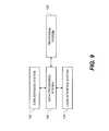
- FIG. 5is a flow diagram according to an embodiment of the present invention.
- FIG. 6is a flow diagram according to another embodiment of the present invention.
- FIG. 7is a flow diagram according to an alternative embodiment of the present invention.
- FIG. 8is a prior-art representation of a two-dimensional optical matrix QR barcode with graphic elements
- FIG. 9is a schematic of a system useful in various embodiments of the present invention.
- FIG. 10is an illustration of an embodiment of a computer system useful in various embodiments of the present invention.
- FIG. 11is an illustration of an embodiment of a desktop computer, work station, or kiosk that is used in a system of FIG. 10 ;
- FIG. 12is an illustration of an embodiment of a mobile communication device that is used in a system of FIG. 10 .
- a machine-readable optical code 1 formed on a substrate 315includes a first code 310 including a plurality of first elements 312 formed on or in the substrate 315 , the first code 310 specifying first information.
- Each first element 312is the smallest information-carrying structure, for example a bit of information.
- the first elements 312are either dark ( 6 in FIG. 3 ) or light ( 7 in FIG. 3 ).
- One or more of the first elements 312includes a second code 320 on or in the substrate 315 , the second code 320 including a plurality of second elements 322 specifying second information.
- the second elements 322are either dark ( 6 in FIG. 3 ) or light ( 7 in FIG. 3 ).
- the first code 310 and the second code 320are machine-readable optical codes.
- the second code 320includes one or more first elements 312 and is a portion of and embedded within the first code 310 .
- the machine-readable optical code 1is a multi-level code having a hierarchy of different codes, each capable of encoding different information. Each of the different codes in the hierarchy can have a different resolution. Enlarged portion view A of FIG. 1 illustrates second code 320 in more detail.
- the first code 310is a one-dimensional barcode, a two-dimensional matrix barcode, or a QR code.
- the second code 320is a one-dimensional barcode, a two-dimensional matrix barcode, or a QR code.
- each of the first and second codes 310 , 320have the same format, so that they have the same structure and are printed, displayed or read using the same hardware and software tools.
- the first code 310 , second code 320 , and a third code 330are QR codes.
- the second code 320is formed in a plurality of contiguous first elements 312 .
- the second code 320is made up of four adjacent and contiguous first elements 312 arranged in a two-by-two square matrix.
- the second code 320is made up of a single one of the first elements 312 .
- the machine-readable optical code 1can include a plurality of second codes 320 , 320 A in or on the substrate 315 , each second code 320 formed from different one or more first elements 312 .
- the second elements 322have a higher resolution than the first elements 312 and are formed at a higher resolution.
- elements formed at a higher resolutionhave a greater number of distinguishable elements per linear distance or per area.
- a common forming mechanisme.g. printer, display
- the first elements 312can be formed with a first device capable of forming elements at a first resolution
- the second elements 322are formed with a second device capable of forming elements at a second, higher resolution.
- the first elements 312are printed at a higher rate although the second elements 322 are printed with the same device at a slower rate.
- the rateis the number of elements printed per unit time.
- the second elements 322are printed at a higher resolution.
- the first and second informationencode related information.
- the second informationcan provide more detail on the same topic as the first information.
- both the first code 310 and the second code 320are visually perceptible to a human.
- the first code 310is visually perceptible to a human and the second code 320 is not visually perceptible to a human.
- the second code 320is microscopic.
- a billboard 340 having a paper or plastic substrate 315includes the first code 310 and the second code 320 printed thereon.
- the first code 310is recorded from a first distance D 1 , for example with an image reader 350 such as a digital camera having adequate resolution to distinguish the first elements 312 of the first code 310 but not necessarily having adequate resolution to distinguish the second elements 322 of the second code 320 .
- the first code 310is visually perceptible and machine readable at a first distance D 1 and the second code 320 is visually perceptible and machine readable at a second distance D 2 less than the first distance D 1 .
- the image recordis decoded using known image processing techniques to determine the first information, for example using a processor and user interface 352 on the image reader 350 .
- An alternative image reader 350is a cellular telephone with an integrated digital camera 350 , a processor and user interface 352 , and software for decoding recorded optical codes.
- Other image readers 350can include laser scanners or linear scanners.
- Such image readers 350 and recordersare known in the art, as are processors and software for decoding recorded optical codes. If the first information is of interest, for example in conjunction with other information on the billboard 340 , another image record is made at a closer distance D 2 with the same image reader 350 (or a different image reader).
- the image reader 350(for example, a digital camera) has a limited focal range with a differential capability to record the first code 310 and the smaller second code 320 .
- Alternative useful substrates 315include, without limitation, posters and large displays, especially those in commercial locations. Such billboards, posters, and displays are used for commercial activities, particularly for advertising.
- the second code 320 formed in the first element(s) 312meets the requirements for decoding the first code 310 .
- the second codes 320provide one or more distinguishable first elements 312 .
- each elementhas a binary state, either light or dark, and is decoded as either light or dark to decode the information in the barcode, for example by comparing the average darkness of the element area to one or more threshold values.
- the second code 320is read on average as either a light or a dark first element 312 , depending on the information carried in the one or more second elements 322 that form the second code 320 . This can limit the second information encoded in the second code 320 .
- a discriminatorthat uses one or more thresholds to select between binary light and dark states is set at such levels that the aggregate lightness or darkness of the second codes 320 is determined to be either dark or light, as desired.
- the discriminatorcan set a threshold level so that if only 10% of the area in the first element 312 is dark, the first element 312 is determined to be dark.
- image processing softwareto average the pixel values over the first element area in an image of the first code 310 , a more robust and flexible system is provided.
- second codes 320that occupy the locations of more than one first elements 312 (e.g.
- each section of the second code 320is decoded separately and differently.
- the location of the second code 320 in the first code 310is determined by matching portions of the second code 320 to first elements 312 , so that the first elements 312 are decoded properly. For example, if the second code 320 is determined to be dark, the second code 320 is located in a dark first element 312 . If the second code 320 is determined to be light, the second code 320 is located in a light first element 312 . If the second code 320 has quadrants that have a light and dark arrangements, the second code 320 is located in a first element area having the same arrangement.
- some codeshave a greater number of dark elements as the quantity of encoded data increases.
- the embedded codescan include redundant or additional data that controls the element density within a code to control the lightness or darkness of the code with respect to the threshold.
- the encoded datais selected to make the code light or dark.
- the present inventionis used to provide information associated with images.
- the first code 310is printed in association with an image and the first or second information is relevant to the image.
- the first or second informationis provided by image metadata.
- a method of making a machine-readable optical code 1 formed on a substrate 315includes receiving information (step 101 ), encoding the information (step 102 ), and forming the machine-readable optical first code 310 including a plurality of first elements 312 on or in the substrate 315 (step 105 ).
- the machine-readable optical first code 310specifies first information.
- One or more of the first elements 312form the machine-readable optical second code 320 including a plurality of second elements 322 on the substrate 315 , the second code 320 specifying second information.
- the first code 310 and the second code 320are machine-readable optical codes.
- the first elements 312 and second elements 322are printed on the substrate 315 with the same printing device.
- the first elements 312are printed (step 106 ) at a first rate and the second elements 322 are printed (step 107 ) at a second rate slower than the first rate.
- the second code 320is located in first element(s) 312 for which the overall lightness or darkness of the second code 320 is matched to the lightness or darkness of the first element(s) 312 (step 110 ).
- a method of decoding a machine-readable optical code 1includes using the first image reader 350 to record (step 200 ) the first code 310 on the substrate 315 to form a first recorded image.
- the first code 310specifies first information and includes a plurality of first elements 312 specifying the first information stored within the first code 312 .
- One or more of the first elements 312form the second code 320 on the substrate 315 , the second code 320 specifying second information and including a plurality of second elements 322 specifying the second information encoded within the second code 320 .
- the first code 310 and the second code 320are machine-readable optical codes.
- the processor 352is used to decode (step 205 ) the first information from the first recorded image.
- a second image reader 350is used to record the second code 320 (step 210 ) to form a second recorded image and the processor 352 is used to decode the second information (step 215 ) from the second recorded image whereby the machine-readable optical code is decoded.
- the decoded informationis presented (step 220 ).
- the first image reader 350 and the second image reader 350can be the same image reader 350 .
- the second image reader 350has a higher magnification than the first image reader 350 .
- the image reader 350is an area recorder (for example using an area electronic imager), a linear recorder (for example using a linear electronic imager), or a laser scanner.
- the image reader 350can be a digital camera, a cellular telephone that incorporates a digital camera, or a portable computer that incorporates a digital camera.
- the decoded informationis displayed on a display 354 , for example a display associated with the processor 352 or image reader 350 .
- the processor 352is a part of the image reader 350 .
- the image reader 350 , the processor 352 , and the display 354are parts of a common mobile communication device, such as a cellular telephone or smart phone.
- the first code 310is recorded at a first resolution and the second code 320 is recorded at a second resolution higher than the first resolution.
- the first code 310is recorded at a first distance D 1 and the second code 320 is recorded at a second distance D 2 less than the first distance D 1 .
- a method of the present inventionfurther includes visually perceiving the first code 310 at the first distance D 1 , recording the first code 310 , visually perceiving the second code 320 at the second distance D 2 less than the first distance D 1 , and recording the second code 320 .
- the first and second codes 310 , 320use the same code format, so the same software tools are used to locate and decode the first and second codes 310 , 320 .
- the code formatcan be a one-dimensional or two-dimensional barcode or matrix code, such as a QR code.
- Software tools for coding or decoding such codesare known in the art.
- FIG. 9is a high-level diagram showing the components of a system useful for practicing various embodiments of the present invention.
- the systemincludes a data processing system 150 , a peripheral system 120 , a user interface system 130 , and a data storage system 140 .
- the peripheral system 120 , the user interface system 130 and the data storage system 140are communicatively connected to the data processing system 150 .
- the data processing system 150includes one or more data processing devices that implement the processes of the various embodiments of the present invention, including the example processes described herein.
- the phrases “data processing device” or “data processor”are intended to include any data processing device, such as a central processing unit (“CPU”), a desktop computer, a laptop computer, a mainframe computer, a personal digital assistant, a BlackberryTM, a digital camera, a digital picture frame, cellular phone, a smart phone or any other device for processing data, managing data, communicating data, or handling data, whether implemented with electrical, magnetic, optical, biological components, or otherwise.
- CPUcentral processing unit
- BlackberryTMa digital camera
- digital picture framecellular phone
- smart phoneany other device for processing data, managing data, communicating data, or handling data, whether implemented with electrical, magnetic, optical, biological components, or otherwise.
- the data storage system 140includes one or more processor-accessible memories configured to store information, including the information needed to execute the processes of the various embodiments of the present invention, including the example processes described herein.
- the data storage system 140is a distributed processor-accessible memory system including multiple processor-accessible memories communicatively connected to the data processing system 150 via a plurality of computers or devices.
- the data storage system 140need not be a distributed processor-accessible memory system and, consequently, can include one or more processor-accessible memories located within a single data processor or device.
- processor-accessible memoryis intended to include any processor-accessible data storage device, whether volatile or nonvolatile, electronic, magnetic, optical, or otherwise, including but not limited to, registers, caches, floppy disks, hard disks, Compact Discs, DVDs, flash memories, ROMs, and RAMs.
- the phrase “communicatively connected”is intended to include any type of connection, whether wired or wireless, between devices, data processors, or programs in which data is communicated.
- the phrase “communicatively connected”is intended to include a connection between devices or programs within a single data processor, a connection between devices or programs located in different data processors, and a connection between devices not located in data processors.
- the data storage system 140is shown separately from the data processing system 150 , one skilled in the art will appreciate that the data storage system 140 can be stored completely or partially within the data processing system 150 .
- the peripheral system 120 and the user interface system 130are shown separately from the data processing system 150 , one skilled in the art will appreciate that one or both of such systems can be stored completely or partially within the data processing system 150 .
- the peripheral system 120can include one or more devices configured to provide digital content records to the data processing system 150 .
- the peripheral system 120can include digital still cameras, digital video cameras, cellular phones, smart phones, or other data processors.
- the data processing system 150upon receipt of digital content records from a device in the peripheral system 120 , can store such digital content records in the data storage system 140 .
- the user interface system 130can include a mouse, a keyboard, another computer, or any device or combination of devices from which data is input to the data processing system 150 .
- the peripheral system 120is shown separately from the user interface system 130 , the peripheral system 120 can be included as part of the user interface system 130 .
- the user interface system 130also can include a display device, a processor-accessible memory, or any device or combination of devices to which data is output by the data processing system 150 .
- the user interface system 130includes a processor-accessible memory, such memory can be part of the data storage system 140 even though the user interface system 130 and the data storage system 140 are shown separately in FIG. 9 .
- the system of FIG. 9can be a cellular telephone or digital camera with data processing system ( 150 ) for recording images from the incorporated image sensor 39 , encoding or decoding the multi-resolution codes described herein, and presenting information on the display 354 .
- a computer system for coding and decoding codes, printing codes, reading codes, and presenting code informationincludes a electronic computer system 20 , for example a computer server.
- the electronic computer system 20is connected to a remote electronic computer system 35 , for example a remote client computer, through a computer network, the electronic computer system 20 including memory 40 .
- the remote electronic computer system 35can have a display 66 (e.g. corresponding to display 354 ) for displaying code information or otherwise providing a user interface.
- FIG. 10illustrates an embodiment of an electronic computer system 20 , for example a computer, which is used in generating and printing codes.
- the electronic computer system 20includes a source of content data files 24 , a user input system 26 and an output system 28 connected to a processor 34 .
- the source of content data files 24 , user-input system 26 or output system 28 and processor 34is positioned within a housing 22 as illustrated.
- circuits and systems of the source of content data files 24 , user input system 26 or output system 28are positioned in whole or in part outside of housing 22 .
- the source of content data files 24can include any form of electronic or other circuit or system that can supply digital data to processor 34 from which processor 34 can derive images that is printed with codes.
- the content data files 24can include, for example and without limitation, still images, image sequences, video graphics, computer-generated images, and image metadata.
- Source of content data files 24can optionally capture images to create content data for use in content data files 24 by use of capture devices located at, or connected to, electronic computer system 20 or can obtain content data files that have been prepared by or using other devices such as the remote electronic computer system 35 .
- source of content data files 24includes sensors 38 , the memory 40 and a communication system 54 .
- Memory 40can include conventional memory devices including solid-state, magnetic, optical or other data-storage devices. Memory 40 is fixed within electronic computer system 20 or it is removable. In the embodiment of FIG. 10 , electronic computer system 20 is shown having a hard drive 42 , a disk drive 44 for a removable disk such as an optical, magnetic or other disk memory (not shown) and a memory card slot 46 that holds a removable memory 48 such as a removable memory card and has a removable memory interface 50 for communicating with removable memory 48 . Data including, but not limited to, control programs, digital images and metadata can also be stored in a remote memory system 52 such as the remote electronic computer system 35 , a personal computer, computer network or other digital system. Remote memory system 52 can also include solid-state, magnetic, optical or other data-storage devices.
- electronic computer system 20has a communication system 54 that in this embodiment is used to communicate with remote electronic computer systems 35 for example including an optional remote memory system 52 , an optional remote display 56 , or optional remote input 58 .
- the optional remote memory system 52 , optional remote display 56 , and optional remote input 58can all be part of the remote electronic computer system 35 having the remote input 58 with remote input controls, and that can communicate with communication system 54 wirelessly as illustrated or can communicate in a wired fashion.
- a local input stationincluding either or both of the local display 66 and local input controls 68 (also referred to herein as “local user input 68 ”) is connected to communication system 54 using a wired or wireless connection.
- Communication system 54can include for example, one or more optical, radio frequency or other transducer circuits or other systems that convert image and other data into a form that is conveyed to a remote device such as the remote memory system 52 or the remote display 56 using an optical signal, radio frequency signal or other form of signal.
- Communication system 54can also be used to receive a digital image and other data from a host or server computer or network (not shown), the remote memory system 52 or the remote input 58 .
- Communication system 54provides processor 34 with information and instructions from signals received thereby.
- communication system 54will be adapted to communicate with the remote memory system 52 by way of a communication network such as a conventional telecommunication or data transfer network such as the internet, a cellular, peer-to-peer or other form of mobile telecommunication network, a local communication network such as wired or wireless local area network or any other conventional wired or wireless data transfer system.
- a communication networksuch as a conventional telecommunication or data transfer network such as the internet, a cellular, peer-to-peer or other form of mobile telecommunication network, a local communication network such as wired or wireless local area network or any other conventional wired or wireless data transfer system.
- the electronic computer system 20can provide web access services to remote electronic computer systems 35 that access the electronic computer system 20 through a web browser.
- the remote electronic computer system 35can provide web services to electronic computer system 20 depending on the configurations of the systems.
- User input system 26provides a way for a user 72 of electronic computer system 20 to provide instructions to processor 34 . This permits the user 72 to make a designation of content data files to be used in generating an image-enhanced output product and to select an output form for the output product.
- User input system 26can also be used for a variety of other purposes including, but not limited to, permitting the user 72 to arrange, organize and edit content data files to be incorporated into the image-enhanced output product, to provide information about the user or audience, to provide annotation data such as voice and text data, to identify characters in the content data files, and to perform such other interactions with electronic computer system 20 as are described herein.
- user input system 26includes the optional remote input 58 including a remote keyboard 58 a , a remote mouse 58 b , and a remote control 58 c and the local user input 68 including a local keyboard 68 a and a local mouse 68 b.
- Remote input 58can take a variety of forms, including, but not limited to, the remote keyboard 58 a , remote mouse 58 b or remote control 58 c illustrated in FIG. 10 .
- local user input 68can take a variety of forms. In the embodiment of FIG. 10 , local display 66 and local user input 68 are shown directly connected to processor 34 .
- local user input 68can take the form of an editing area 70 such as a home computer, an editing studio, or kiosk that can also be a stand-alone computer system with the processor 34 and local disk drive 44 or other memory or the remote electronic computer system 35 .
- the user 72is seated before a console including local keyboard 68 a and mouse 68 b and the local display 66 which is capable, for example, of displaying multimedia content, for example in a graphic user interface.
- editing area 70can also have sensors 38 including, but not limited to, image sensors 39 , audio sensors 74 and other sensors such as multispectral sensors that can monitor user 72 during a production session or provide other information such as images.
- Output system 28( FIG. 10 ) is used for rendering images, text, codes, or other graphical representations.
- output system 28can include any conventional structure or system that is known for printing or recording images on an output device 32 including, but not limited to, printer 29 .
- Printer 29can record images or codes on a tangible surface 30 using a variety of known technologies including, but not limited to, conventional four-color offset separation printing or other contact printing, silk screening, dry electrophotography such as is used in the NexPress 2100 printer sold by Eastman Kodak Company, Rochester, N.Y., USA, thermal printing technology, drop-on-demand inkjet technology and continuous inkjet technology.
- printer 29will be described as of a type that generates color images. It will be appreciated that this is not necessary and that the claimed methods and apparatuses herein are practiced with the printer 29 that prints monotone images such as black and white, grayscale, or sepia toned images.
- the electronic computer systems 20 , 35with which the user 72 interacts to define a user-personalized image product can be separated from the remote electronic computer system 35 ) connected to the printer 29 , so that the specification of the image product is remote from its production.
- the source of content data files 24 , user input system 26 and output system 28can share components.
- Processor 34operates electronic computer system 20 based upon signals from user input system 26 , sensors 38 , memory 40 and communication system 54 .
- Processor 34can include, but is not limited to, a programmable digital computer, a programmable microprocessor, a programmable logic processor, a series of electronic circuits, a series of electronic circuits reduced to the form of an integrated circuit, or a series of discrete components.
- the remote electronic computer system 35is a mobile communication device 80 , for example a cellular telephone, a smart phone, or a wirelessly connected hand-held computer such as a tablet computer.
- the mobile communication device 80can include the display 66 or a user-input system incorporating the local input 68 , keyboard 68 a and the image reader 350 (for example, a digital camera with image sensor 39 ).
- the image reader 350can have a variable focus or variable zoom lens, for example to capture images at different resolutions and distances (D 1 and D 2 ). Microscopic lenses can be included.
- the local input 68 devicecan be a touch screen.
- the mobile communication device 80can communicate with electronic computer system 20 directly, for example through a wireless local area network or a point-to-point wireless connection, or indirectly through a cellular telephony network.
- the electronic computer system 20can be a computer server, for example providing browser-based web pages to a remote electronic computer system 35 , 80 .
- the mobile communication device 80can incorporate the image reader 350 (for example, a digital camera with image sensor 39 ) to enable image reading, the display 354 (corresponding to display 66 ) and a processor (not shown in FIG. 12 ).
- the mobile communication device 80can correspond to a remote electronic computer system 35 , or a standalone computer system that provides the image reading (step 200 ), decoding (steps 205 , 215 ), and presenting steps (step 220 ) useful in the present invention and illustrated in FIG. 7 .
- the electronic computer system 20 of FIG. 8is useful for receiving information, encoding the information, and outputting (e.g. by printing) the information in conjunction with other printed material such as images or graphic information.
- Any one of the electronic computer system 20 , remote electronic computer system 35 , or the mobile communication device 80can execute software programs on the internal processor 34 .
- the software programscan interact with the user 72 through a user interface (e.g. local display 66 and local input 68 ) or with remote computers to accomplish the programmed task.
- the software programscan execute algorithms to analyze data (e.g. digital image files) or to compute useful values.
- a computer software program productcan include one or more non-transitory, tangible, computer readable storage medium, for example; magnetic storage media such as magnetic disk (such as a floppy disk) or magnetic tape; optical storage media such as optical disk, optical tape, or machine readable bar code; solid-state electronic storage devices such as random access memory (RAM), or read-only memory (ROM); or any other physical device or media employed to store a computer program having instructions for controlling one or more computers to practice the present invention.
- magnetic storage mediasuch as magnetic disk (such as a floppy disk) or magnetic tape
- optical storage mediasuch as optical disk, optical tape, or machine readable bar code
- solid-state electronic storage devicessuch as random access memory (RAM), or read-only memory (ROM); or any other physical device or media employed to store a computer program having instructions for controlling one or more computers to practice the present invention.
Landscapes
- Physics & Mathematics (AREA)
- Engineering & Computer Science (AREA)
- General Physics & Mathematics (AREA)
- Theoretical Computer Science (AREA)
- Health & Medical Sciences (AREA)
- Electromagnetism (AREA)
- General Health & Medical Sciences (AREA)
- Toxicology (AREA)
- Artificial Intelligence (AREA)
- Computer Vision & Pattern Recognition (AREA)
- Editing Of Facsimile Originals (AREA)
Abstract
Description
- A, B enlarged portion view
- D1 first distance
- D2 second distance
- 1 machine-readable optical code
- 5 two-dimensional code, QR code, matrix bar code
- 6 dark elements
- 7 light elements
- 8 graphic elements
- 20 electronic computer system
- 22 housing
- 24 source of content data files
- 26 user input system
- 28 output system
- 29 printer
- 30 tangible surface
- 32 output device
- 34 processor
- 35 remote electronic computer system
- 38 sensors
- 39 image sensors
- 40 memory
- 42 hard drive
- 44 disk drive
- 46 memory card slot
- 48 removable memory
- 50 memory interface
- 52 remote memory system
- 54 communication system
- 56 remote display
- 58 remote input
- 58aremote keyboard
- 58bremote mouse
- 58cremote control
- 66 local display
- 68 local input
- 68alocal keyboard
- 68blocal mouse
- 70 editing area (home computer, editing studio, or kiosk)
- 72 user
- 74 audio sensors
- 80 mobile communication device
- 100 provide substrate step
- 101 receive information step
- 102 encode information step
- 105 form code on substrate step
- 106 print first code at fast rate step
- 107 print second code at slow rate step
- 110 locate second code in first element location step
- 120 peripheral system
- 130 user interface system
- 140 data storage system
- 150 data processing system
- 200 record first code step
- 205 decode first code step
- 210 record second code step
- 215 decode second code step
- 220 present decoded information step
- 310 first code
- 312 first element
- 315 substrate
- 320 second code
- 320A second code
- 322 second element
- 330 third code
- 332 third element
- 340 billboard
- 350 image reader (digital camera)
- 352 processor and user interface
- 354 display
Claims (19)
Priority Applications (1)
| Application Number | Priority Date | Filing Date | Title |
|---|---|---|---|
| US13/080,846US8807435B2 (en) | 2011-04-06 | 2011-04-06 | Decoding multi-resolution optical codes |
Applications Claiming Priority (1)
| Application Number | Priority Date | Filing Date | Title |
|---|---|---|---|
| US13/080,846US8807435B2 (en) | 2011-04-06 | 2011-04-06 | Decoding multi-resolution optical codes |
Publications (2)
| Publication Number | Publication Date |
|---|---|
| US20120256000A1 US20120256000A1 (en) | 2012-10-11 |
| US8807435B2true US8807435B2 (en) | 2014-08-19 |
Family
ID=46965318
Family Applications (1)
| Application Number | Title | Priority Date | Filing Date |
|---|---|---|---|
| US13/080,846Expired - Fee RelatedUS8807435B2 (en) | 2011-04-06 | 2011-04-06 | Decoding multi-resolution optical codes |
Country Status (1)
| Country | Link |
|---|---|
| US (1) | US8807435B2 (en) |
Cited By (5)
| Publication number | Priority date | Publication date | Assignee | Title |
|---|---|---|---|---|
| CN104268610A (en)* | 2014-09-11 | 2015-01-07 | 重庆大学 | Method for generating and reading graded QR code |
| US20150205984A1 (en)* | 2013-08-06 | 2015-07-23 | Intel Corporation | Optical communication using differential images |
| US20160078333A1 (en)* | 2013-07-24 | 2016-03-17 | Hewlet-Packard Development Company, L.P. | Encoding an information object |
| US20160092760A1 (en)* | 2012-12-19 | 2016-03-31 | Mitsubishi Electric Corporation | Information code, information code producing method, information code reader, and system which uses information code |
| US10147028B2 (en) | 2014-10-07 | 2018-12-04 | Denso Wave Incorporated | Method and apparatus for producing information code having an image display region with a code figure |
Families Citing this family (31)
| Publication number | Priority date | Publication date | Assignee | Title |
|---|---|---|---|---|
| US8689255B1 (en) | 2011-09-07 | 2014-04-01 | Imdb.Com, Inc. | Synchronizing video content with extrinsic data |
| US20130320094A1 (en)* | 2012-05-30 | 2013-12-05 | Mark Slusar | Dynamic embedded machine readable encoding |
| US8955021B1 (en) | 2012-08-31 | 2015-02-10 | Amazon Technologies, Inc. | Providing extrinsic data for video content |
| US9113128B1 (en) | 2012-08-31 | 2015-08-18 | Amazon Technologies, Inc. | Timeline interface for video content |
| US9389745B1 (en) | 2012-12-10 | 2016-07-12 | Amazon Technologies, Inc. | Providing content via multiple display devices |
| US10424009B1 (en) | 2013-02-27 | 2019-09-24 | Amazon Technologies, Inc. | Shopping experience using multiple computing devices |
| US11019300B1 (en) | 2013-06-26 | 2021-05-25 | Amazon Technologies, Inc. | Providing soundtrack information during playback of video content |
| US10275624B2 (en) | 2013-10-29 | 2019-04-30 | Hand Held Products, Inc. | Hybrid system and method for reading indicia |
| CN105706118B (en) | 2013-10-30 | 2019-01-04 | 凸版Tdk标签株式会社 | The method for generating two-dimensional bar code, the device for generating two-dimensional bar code, the method for reading two-dimensional bar code, device, two-dimensional bar code and the program for reading two-dimensional bar code |
| ES2718528T3 (en)* | 2013-11-07 | 2019-07-02 | Scantrust Sa | Two-dimensional barcode and authentication procedure of said barcode |
| US9838740B1 (en) | 2014-03-18 | 2017-12-05 | Amazon Technologies, Inc. | Enhancing video content with personalized extrinsic data |
| US9791865B2 (en)* | 2014-10-29 | 2017-10-17 | Amazon Technologies, Inc. | Multi-scale fiducials |
| CN105654006B (en)* | 2014-11-13 | 2018-05-29 | 阿里巴巴集团控股有限公司 | A two-dimensional code scanning interaction method and device |
| CN107004150B (en)* | 2014-11-25 | 2020-03-17 | 因富通国际有限公司 | Information bearing device |
| JP6465051B2 (en)* | 2016-03-04 | 2019-02-06 | 株式会社デンソーウェーブ | Information code and information code reading method |
| USD813302S1 (en)* | 2016-06-08 | 2018-03-20 | Bank Of America Corporation | Card with 2D barcode |
| CN106897341A (en)* | 2016-07-08 | 2017-06-27 | 阿里巴巴集团控股有限公司 | 2 D code information querying method, server, client and system |
| EP3285197A1 (en)* | 2016-08-19 | 2018-02-21 | Sicpa Holding Sa | Providing and reading a marking on an item |
| CN106649437A (en)* | 2016-09-08 | 2017-05-10 | 广州视睿电子科技有限公司 | Bar code scanning method and system |
| JP7088597B2 (en)* | 2016-09-28 | 2022-06-21 | スリーエム イノベイティブ プロパティズ カンパニー | Shielding resistant optics for machine-readable articles |
| US10691908B2 (en) | 2016-09-28 | 2020-06-23 | 3M Innovative Properties Company | Hierarchichal optical element sets for machine-read articles |
| US11250303B2 (en) | 2016-09-28 | 2022-02-15 | 3M Innovative Properties Company | Multi-dimensional optical code with static data and dynamic lookup data optical element sets |
| CN107291224B (en)* | 2017-06-07 | 2021-01-29 | 驭势(上海)汽车科技有限公司 | Equipment control method and equipment control device |
| JP6949658B2 (en)* | 2017-10-24 | 2021-10-13 | 清水建設株式会社 | Information communication systems, information media, and readers |
| SG10201801042QA (en) | 2018-02-07 | 2019-09-27 | I Sprint Innovations Pte Ltd | Two-Dimensional Barcode Generating Method, Verification Method, Server and Two-Dimensional Barcode |
| EP3776336A1 (en) | 2018-03-27 | 2021-02-17 | 3M Innovative Properties Company | Identifier allocation for optical element sets in machine-read articles |
| CN108955667A (en)* | 2018-08-02 | 2018-12-07 | 苏州中德睿博智能科技有限公司 | A kind of complex navigation method, apparatus and system merging laser radar and two dimensional code |
| US11915097B1 (en) | 2020-01-14 | 2024-02-27 | Apple Inc. | Visual marker with user selectable appearance |
| US11755854B2 (en)* | 2020-07-14 | 2023-09-12 | Apple Inc. | Visual marker |
| US11734527B1 (en) | 2020-07-23 | 2023-08-22 | Apple Inc. | Optimal matching of image portion data sets |
| JP2023170171A (en)* | 2022-05-18 | 2023-12-01 | 東芝テック株式会社 | Printed material and manufacturing method of printed material |
Citations (11)
| Publication number | Priority date | Publication date | Assignee | Title |
|---|---|---|---|---|
| US6726104B2 (en) | 2000-12-18 | 2004-04-27 | Symbol Technologies, Inc. | Scaling techniques for printing bar code symbols |
| US20040256462A1 (en)* | 2003-04-17 | 2004-12-23 | Staffan Solen | Method and device for recording of data |
| JP2005301656A (en)* | 2004-04-12 | 2005-10-27 | Sakae Shibusawa | Information recording method, device therefor, and multilayer code |
| US20050269416A1 (en)* | 2004-06-07 | 2005-12-08 | Pitney Bowes Incorporated | Barcode with enhanced additional stored data |
| US20070143737A1 (en)* | 2005-12-19 | 2007-06-21 | Qingfeng Huang | Using multi-resolution visual codes to facilitate information browsing in the physical world |
| US7273175B2 (en) | 2004-09-07 | 2007-09-25 | Canon Kabushiki Kaisha | Method, an apparatus and a storage medium for locating QR codes |
| US20090088203A1 (en)* | 2007-09-27 | 2009-04-02 | Hand Held Products, Inc. | Wireless bar code transaction device |
| US7702162B2 (en) | 2004-11-05 | 2010-04-20 | Colorzip Media, Inc. | Mixed code, and method and apparatus for generating the same |
| US7835037B2 (en) | 2006-01-17 | 2010-11-16 | Ricoh Company, Ltd. | Image processing apparatus and image processing method |
| US7841531B2 (en) | 2004-10-27 | 2010-11-30 | Denso Corporation | Camera operating system and matrix code decoding device |
| US7886978B2 (en) | 2007-09-20 | 2011-02-15 | Microsoft Corporation | Techniques for decoding images of barcodes |
- 2011
- 2011-04-06USUS13/080,846patent/US8807435B2/ennot_activeExpired - Fee Related
Patent Citations (11)
| Publication number | Priority date | Publication date | Assignee | Title |
|---|---|---|---|---|
| US6726104B2 (en) | 2000-12-18 | 2004-04-27 | Symbol Technologies, Inc. | Scaling techniques for printing bar code symbols |
| US20040256462A1 (en)* | 2003-04-17 | 2004-12-23 | Staffan Solen | Method and device for recording of data |
| JP2005301656A (en)* | 2004-04-12 | 2005-10-27 | Sakae Shibusawa | Information recording method, device therefor, and multilayer code |
| US20050269416A1 (en)* | 2004-06-07 | 2005-12-08 | Pitney Bowes Incorporated | Barcode with enhanced additional stored data |
| US7273175B2 (en) | 2004-09-07 | 2007-09-25 | Canon Kabushiki Kaisha | Method, an apparatus and a storage medium for locating QR codes |
| US7841531B2 (en) | 2004-10-27 | 2010-11-30 | Denso Corporation | Camera operating system and matrix code decoding device |
| US7702162B2 (en) | 2004-11-05 | 2010-04-20 | Colorzip Media, Inc. | Mixed code, and method and apparatus for generating the same |
| US20070143737A1 (en)* | 2005-12-19 | 2007-06-21 | Qingfeng Huang | Using multi-resolution visual codes to facilitate information browsing in the physical world |
| US7835037B2 (en) | 2006-01-17 | 2010-11-16 | Ricoh Company, Ltd. | Image processing apparatus and image processing method |
| US7886978B2 (en) | 2007-09-20 | 2011-02-15 | Microsoft Corporation | Techniques for decoding images of barcodes |
| US20090088203A1 (en)* | 2007-09-27 | 2009-04-02 | Hand Held Products, Inc. | Wireless bar code transaction device |
Cited By (9)
| Publication number | Priority date | Publication date | Assignee | Title |
|---|---|---|---|---|
| US20160092760A1 (en)* | 2012-12-19 | 2016-03-31 | Mitsubishi Electric Corporation | Information code, information code producing method, information code reader, and system which uses information code |
| US10062022B2 (en)* | 2012-12-19 | 2018-08-28 | Denso Wave Incorporated | Information code, information code producing method, information code reader, and system which uses information code |
| US20160078333A1 (en)* | 2013-07-24 | 2016-03-17 | Hewlet-Packard Development Company, L.P. | Encoding an information object |
| US20150205984A1 (en)* | 2013-08-06 | 2015-07-23 | Intel Corporation | Optical communication using differential images |
| US9361498B2 (en)* | 2013-08-06 | 2016-06-07 | Intel Corporation | Optical communication using differential images |
| US9704083B2 (en) | 2013-08-06 | 2017-07-11 | Intel Corporation | Optical communication using differential images |
| CN104268610A (en)* | 2014-09-11 | 2015-01-07 | 重庆大学 | Method for generating and reading graded QR code |
| CN104268610B (en)* | 2014-09-11 | 2017-09-01 | 重庆大学 | A hierarchical QR code generation method and reading method |
| US10147028B2 (en) | 2014-10-07 | 2018-12-04 | Denso Wave Incorporated | Method and apparatus for producing information code having an image display region with a code figure |
Also Published As
| Publication number | Publication date |
|---|---|
| US20120256000A1 (en) | 2012-10-11 |
Similar Documents
| Publication | Publication Date | Title |
|---|---|---|
| US8807435B2 (en) | Decoding multi-resolution optical codes | |
| US8439275B2 (en) | Multi-resolution optical codes | |
| US8511575B2 (en) | Digital image file including optical code | |
| US8995032B2 (en) | Producing an image and optical file from a visible first digital image and from a visible second digital image of a machine-readable optical code which encodes information associated with or derived from the first digital image | |
| CN101779182B (en) | Perform operations on one or more images with a printer | |
| US10614540B2 (en) | System and method for embedding a two dimensional code in video images | |
| US20130073687A1 (en) | System for managing information using machine-readable codes | |
| US20140023281A1 (en) | Continuation of multi-element image templates | |
| JP2006099767A (en) | Image placement method, image placement system, image placement apparatus and computer-readable storage medium in electronic document | |
| WO2008075748A1 (en) | Method for acquiring simulation parameter in invisible code printing support system and its system | |
| US20130026223A1 (en) | Selecting images using machine-readable codes | |
| CN102336069A (en) | Printer with picture clipping function and picture clipping method | |
| US20150286832A1 (en) | Photobook with augmented social capability | |
| US8646691B2 (en) | Apparatus and method for using machine-readable codes | |
| US8596523B2 (en) | Index print with machine-readable codes | |
| US8967482B2 (en) | Image selection method using machine-readable codes | |
| US11721051B2 (en) | Imaging product selection system | |
| JP4911903B2 (en) | Display device, display system, display method, and program | |
| US7681797B2 (en) | Image processing apparatus, method for controlling the same, program, and storage medium | |
| US8763904B2 (en) | Visibly forming an image and optical code | |
| US8534542B2 (en) | Making an ordered element list | |
| US10216990B2 (en) | Selection of machine-readable link type | |
| JP2007194793A (en) | Image forming apparatus | |
| JP5924035B2 (en) | Information processing apparatus and information processing program | |
| JP4983489B2 (en) | Information processing apparatus and information processing program |
Legal Events
| Date | Code | Title | Description |
|---|---|---|---|
| AS | Assignment | Owner name:EASTMAN KODAK COMPANY, NEW YORK Free format text:ASSIGNMENT OF ASSIGNORS INTEREST;ASSIGNOR:COK, RONALD STEVEN;REEL/FRAME:026081/0914 Effective date:20110405 | |
| AS | Assignment | Owner name:CITICORP NORTH AMERICA, INC., AS AGENT, NEW YORK Free format text:SECURITY INTEREST;ASSIGNORS:EASTMAN KODAK COMPANY;PAKON, INC.;REEL/FRAME:028201/0420 Effective date:20120215 | |
| AS | Assignment | Owner name:WILMINGTON TRUST, NATIONAL ASSOCIATION, AS AGENT, MINNESOTA Free format text:PATENT SECURITY AGREEMENT;ASSIGNORS:EASTMAN KODAK COMPANY;PAKON, INC.;REEL/FRAME:030122/0235 Effective date:20130322 Owner name:WILMINGTON TRUST, NATIONAL ASSOCIATION, AS AGENT, Free format text:PATENT SECURITY AGREEMENT;ASSIGNORS:EASTMAN KODAK COMPANY;PAKON, INC.;REEL/FRAME:030122/0235 Effective date:20130322 | |
| AS | Assignment | Owner name:BARCLAYS BANK PLC, AS ADMINISTRATIVE AGENT, NEW YORK Free format text:INTELLECTUAL PROPERTY SECURITY AGREEMENT (SECOND LIEN);ASSIGNORS:EASTMAN KODAK COMPANY;FAR EAST DEVELOPMENT LTD.;FPC INC.;AND OTHERS;REEL/FRAME:031159/0001 Effective date:20130903 Owner name:JPMORGAN CHASE BANK, N.A., AS ADMINISTRATIVE, DELAWARE Free format text:INTELLECTUAL PROPERTY SECURITY AGREEMENT (FIRST LIEN);ASSIGNORS:EASTMAN KODAK COMPANY;FAR EAST DEVELOPMENT LTD.;FPC INC.;AND OTHERS;REEL/FRAME:031158/0001 Effective date:20130903 Owner name:BARCLAYS BANK PLC, AS ADMINISTRATIVE AGENT, NEW YO Free format text:INTELLECTUAL PROPERTY SECURITY AGREEMENT (SECOND LIEN);ASSIGNORS:EASTMAN KODAK COMPANY;FAR EAST DEVELOPMENT LTD.;FPC INC.;AND OTHERS;REEL/FRAME:031159/0001 Effective date:20130903 Owner name:EASTMAN KODAK COMPANY, NEW YORK Free format text:RELEASE OF SECURITY INTEREST IN PATENTS;ASSIGNORS:CITICORP NORTH AMERICA, INC., AS SENIOR DIP AGENT;WILMINGTON TRUST, NATIONAL ASSOCIATION, AS JUNIOR DIP AGENT;REEL/FRAME:031157/0451 Effective date:20130903 Owner name:JPMORGAN CHASE BANK, N.A., AS ADMINISTRATIVE, DELA Free format text:INTELLECTUAL PROPERTY SECURITY AGREEMENT (FIRST LIEN);ASSIGNORS:EASTMAN KODAK COMPANY;FAR EAST DEVELOPMENT LTD.;FPC INC.;AND OTHERS;REEL/FRAME:031158/0001 Effective date:20130903 Owner name:PAKON, INC., NEW YORK Free format text:RELEASE OF SECURITY INTEREST IN PATENTS;ASSIGNORS:CITICORP NORTH AMERICA, INC., AS SENIOR DIP AGENT;WILMINGTON TRUST, NATIONAL ASSOCIATION, AS JUNIOR DIP AGENT;REEL/FRAME:031157/0451 Effective date:20130903 Owner name:BANK OF AMERICA N.A., AS AGENT, MASSACHUSETTS Free format text:INTELLECTUAL PROPERTY SECURITY AGREEMENT (ABL);ASSIGNORS:EASTMAN KODAK COMPANY;FAR EAST DEVELOPMENT LTD.;FPC INC.;AND OTHERS;REEL/FRAME:031162/0117 Effective date:20130903 | |
| FEPP | Fee payment procedure | Free format text:PAYOR NUMBER ASSIGNED (ORIGINAL EVENT CODE: ASPN); ENTITY STATUS OF PATENT OWNER: LARGE ENTITY Free format text:PAYER NUMBER DE-ASSIGNED (ORIGINAL EVENT CODE: RMPN); ENTITY STATUS OF PATENT OWNER: LARGE ENTITY | |
| STCF | Information on status: patent grant | Free format text:PATENTED CASE | |
| MAFP | Maintenance fee payment | Free format text:PAYMENT OF MAINTENANCE FEE, 4TH YEAR, LARGE ENTITY (ORIGINAL EVENT CODE: M1551) Year of fee payment:4 | |
| AS | Assignment | Owner name:KODAK REALTY, INC., NEW YORK Free format text:RELEASE BY SECURED PARTY;ASSIGNOR:JP MORGAN CHASE BANK, N.A., AS ADMINISTRATIVE AGENT;REEL/FRAME:050239/0001 Effective date:20190617 Owner name:KODAK AMERICAS, LTD., NEW YORK Free format text:RELEASE BY SECURED PARTY;ASSIGNOR:JP MORGAN CHASE BANK, N.A., AS ADMINISTRATIVE AGENT;REEL/FRAME:050239/0001 Effective date:20190617 Owner name:KODAK PHILIPPINES, LTD., NEW YORK Free format text:RELEASE BY SECURED PARTY;ASSIGNOR:JP MORGAN CHASE BANK, N.A., AS ADMINISTRATIVE AGENT;REEL/FRAME:050239/0001 Effective date:20190617 Owner name:KODAK IMAGING NETWORK, INC., NEW YORK Free format text:RELEASE BY SECURED PARTY;ASSIGNOR:JP MORGAN CHASE BANK, N.A., AS ADMINISTRATIVE AGENT;REEL/FRAME:050239/0001 Effective date:20190617 Owner name:EASTMAN KODAK COMPANY, NEW YORK Free format text:RELEASE BY SECURED PARTY;ASSIGNOR:JP MORGAN CHASE BANK, N.A., AS ADMINISTRATIVE AGENT;REEL/FRAME:050239/0001 Effective date:20190617 Owner name:QUALEX, INC., NEW YORK Free format text:RELEASE BY SECURED PARTY;ASSIGNOR:JP MORGAN CHASE BANK, N.A., AS ADMINISTRATIVE AGENT;REEL/FRAME:050239/0001 Effective date:20190617 Owner name:PAKON, INC., NEW YORK Free format text:RELEASE BY SECURED PARTY;ASSIGNOR:JP MORGAN CHASE BANK, N.A., AS ADMINISTRATIVE AGENT;REEL/FRAME:050239/0001 Effective date:20190617 Owner name:CREO MANUFACTURING AMERICA LLC, NEW YORK Free format text:RELEASE BY SECURED PARTY;ASSIGNOR:JP MORGAN CHASE BANK, N.A., AS ADMINISTRATIVE AGENT;REEL/FRAME:050239/0001 Effective date:20190617 Owner name:LASER PACIFIC MEDIA CORPORATION, NEW YORK Free format text:RELEASE BY SECURED PARTY;ASSIGNOR:JP MORGAN CHASE BANK, N.A., AS ADMINISTRATIVE AGENT;REEL/FRAME:050239/0001 Effective date:20190617 Owner name:KODAK AVIATION LEASING LLC, NEW YORK Free format text:RELEASE BY SECURED PARTY;ASSIGNOR:JP MORGAN CHASE BANK, N.A., AS ADMINISTRATIVE AGENT;REEL/FRAME:050239/0001 Effective date:20190617 Owner name:KODAK PORTUGUESA LIMITED, NEW YORK Free format text:RELEASE BY SECURED PARTY;ASSIGNOR:JP MORGAN CHASE BANK, N.A., AS ADMINISTRATIVE AGENT;REEL/FRAME:050239/0001 Effective date:20190617 Owner name:NPEC, INC., NEW YORK Free format text:RELEASE BY SECURED PARTY;ASSIGNOR:JP MORGAN CHASE BANK, N.A., AS ADMINISTRATIVE AGENT;REEL/FRAME:050239/0001 Effective date:20190617 Owner name:FAR EAST DEVELOPMENT LTD., NEW YORK Free format text:RELEASE BY SECURED PARTY;ASSIGNOR:JP MORGAN CHASE BANK, N.A., AS ADMINISTRATIVE AGENT;REEL/FRAME:050239/0001 Effective date:20190617 Owner name:FPC, INC., NEW YORK Free format text:RELEASE BY SECURED PARTY;ASSIGNOR:JP MORGAN CHASE BANK, N.A., AS ADMINISTRATIVE AGENT;REEL/FRAME:050239/0001 Effective date:20190617 Owner name:KODAK (NEAR EAST), INC., NEW YORK Free format text:RELEASE BY SECURED PARTY;ASSIGNOR:JP MORGAN CHASE BANK, N.A., AS ADMINISTRATIVE AGENT;REEL/FRAME:050239/0001 Effective date:20190617 | |
| AS | Assignment | Owner name:KODAK AMERICAS, LTD., NEW YORK Free format text:RELEASE BY SECURED PARTY;ASSIGNOR:JP MORGAN CHASE BANK, N.A., AS ADMINISTRATIVE AGENT;REEL/FRAME:049901/0001 Effective date:20190617 Owner name:FAR EAST DEVELOPMENT LTD., NEW YORK Free format text:RELEASE BY SECURED PARTY;ASSIGNOR:JP MORGAN CHASE BANK, N.A., AS ADMINISTRATIVE AGENT;REEL/FRAME:049901/0001 Effective date:20190617 Owner name:CREO MANUFACTURING AMERICA LLC, NEW YORK Free format text:RELEASE BY SECURED PARTY;ASSIGNOR:JP MORGAN CHASE BANK, N.A., AS ADMINISTRATIVE AGENT;REEL/FRAME:049901/0001 Effective date:20190617 Owner name:NPEC, INC., NEW YORK Free format text:RELEASE BY SECURED PARTY;ASSIGNOR:JP MORGAN CHASE BANK, N.A., AS ADMINISTRATIVE AGENT;REEL/FRAME:049901/0001 Effective date:20190617 Owner name:KODAK AVIATION LEASING LLC, NEW YORK Free format text:RELEASE BY SECURED PARTY;ASSIGNOR:JP MORGAN CHASE BANK, N.A., AS ADMINISTRATIVE AGENT;REEL/FRAME:049901/0001 Effective date:20190617 Owner name:LASER PACIFIC MEDIA CORPORATION, NEW YORK Free format text:RELEASE BY SECURED PARTY;ASSIGNOR:JP MORGAN CHASE BANK, N.A., AS ADMINISTRATIVE AGENT;REEL/FRAME:049901/0001 Effective date:20190617 Owner name:QUALEX, INC., NEW YORK Free format text:RELEASE BY SECURED PARTY;ASSIGNOR:JP MORGAN CHASE BANK, N.A., AS ADMINISTRATIVE AGENT;REEL/FRAME:049901/0001 Effective date:20190617 Owner name:EASTMAN KODAK COMPANY, NEW YORK Free format text:RELEASE BY SECURED PARTY;ASSIGNOR:JP MORGAN CHASE BANK, N.A., AS ADMINISTRATIVE AGENT;REEL/FRAME:049901/0001 Effective date:20190617 Owner name:KODAK PORTUGUESA LIMITED, NEW YORK Free format text:RELEASE BY SECURED PARTY;ASSIGNOR:JP MORGAN CHASE BANK, N.A., AS ADMINISTRATIVE AGENT;REEL/FRAME:049901/0001 Effective date:20190617 Owner name:PAKON, INC., NEW YORK Free format text:RELEASE BY SECURED PARTY;ASSIGNOR:JP MORGAN CHASE BANK, N.A., AS ADMINISTRATIVE AGENT;REEL/FRAME:049901/0001 Effective date:20190617 Owner name:KODAK IMAGING NETWORK, INC., NEW YORK Free format text:RELEASE BY SECURED PARTY;ASSIGNOR:JP MORGAN CHASE BANK, N.A., AS ADMINISTRATIVE AGENT;REEL/FRAME:049901/0001 Effective date:20190617 Owner name:PFC, INC., NEW YORK Free format text:RELEASE BY SECURED PARTY;ASSIGNOR:JP MORGAN CHASE BANK, N.A., AS ADMINISTRATIVE AGENT;REEL/FRAME:049901/0001 Effective date:20190617 Owner name:KODAK (NEAR EAST), INC., NEW YORK Free format text:RELEASE BY SECURED PARTY;ASSIGNOR:JP MORGAN CHASE BANK, N.A., AS ADMINISTRATIVE AGENT;REEL/FRAME:049901/0001 Effective date:20190617 Owner name:KODAK PHILIPPINES, LTD., NEW YORK Free format text:RELEASE BY SECURED PARTY;ASSIGNOR:JP MORGAN CHASE BANK, N.A., AS ADMINISTRATIVE AGENT;REEL/FRAME:049901/0001 Effective date:20190617 Owner name:KODAK REALTY, INC., NEW YORK Free format text:RELEASE BY SECURED PARTY;ASSIGNOR:JP MORGAN CHASE BANK, N.A., AS ADMINISTRATIVE AGENT;REEL/FRAME:049901/0001 Effective date:20190617 | |
| AS | Assignment | Owner name:KODAK PHILIPPINES LTD., NEW YORK Free format text:RELEASE BY SECURED PARTY;ASSIGNOR:BARCLAYS BANK PLC;REEL/FRAME:052773/0001 Effective date:20170202 Owner name:LASER PACIFIC MEDIA CORPORATION, NEW YORK Free format text:RELEASE BY SECURED PARTY;ASSIGNOR:BARCLAYS BANK PLC;REEL/FRAME:052773/0001 Effective date:20170202 Owner name:NPEC INC., NEW YORK Free format text:RELEASE BY SECURED PARTY;ASSIGNOR:BARCLAYS BANK PLC;REEL/FRAME:052773/0001 Effective date:20170202 Owner name:KODAK AMERICAS LTD., NEW YORK Free format text:RELEASE BY SECURED PARTY;ASSIGNOR:BARCLAYS BANK PLC;REEL/FRAME:052773/0001 Effective date:20170202 Owner name:EASTMAN KODAK COMPANY, NEW YORK Free format text:RELEASE BY SECURED PARTY;ASSIGNOR:BARCLAYS BANK PLC;REEL/FRAME:052773/0001 Effective date:20170202 Owner name:FAR EAST DEVELOPMENT LTD., NEW YORK Free format text:RELEASE BY SECURED PARTY;ASSIGNOR:BARCLAYS BANK PLC;REEL/FRAME:052773/0001 Effective date:20170202 Owner name:KODAK REALTY INC., NEW YORK Free format text:RELEASE BY SECURED PARTY;ASSIGNOR:BARCLAYS BANK PLC;REEL/FRAME:052773/0001 Effective date:20170202 Owner name:FPC INC., NEW YORK Free format text:RELEASE BY SECURED PARTY;ASSIGNOR:BARCLAYS BANK PLC;REEL/FRAME:052773/0001 Effective date:20170202 Owner name:QUALEX INC., NEW YORK Free format text:RELEASE BY SECURED PARTY;ASSIGNOR:BARCLAYS BANK PLC;REEL/FRAME:052773/0001 Effective date:20170202 Owner name:KODAK (NEAR EAST) INC., NEW YORK Free format text:RELEASE BY SECURED PARTY;ASSIGNOR:BARCLAYS BANK PLC;REEL/FRAME:052773/0001 Effective date:20170202 | |
| AS | Assignment | Owner name:ALTER DOMUS (US) LLC, ILLINOIS Free format text:INTELLECTUAL PROPERTY SECURITY AGREEMENT;ASSIGNOR:EASTMAN KODAK COMPANY;REEL/FRAME:056733/0681 Effective date:20210226 Owner name:ALTER DOMUS (US) LLC, ILLINOIS Free format text:INTELLECTUAL PROPERTY SECURITY AGREEMENT;ASSIGNOR:EASTMAN KODAK COMPANY;REEL/FRAME:056734/0001 Effective date:20210226 Owner name:ALTER DOMUS (US) LLC, ILLINOIS Free format text:INTELLECTUAL PROPERTY SECURITY AGREEMENT;ASSIGNOR:EASTMAN KODAK COMPANY;REEL/FRAME:056734/0233 Effective date:20210226 Owner name:BANK OF AMERICA, N.A., AS AGENT, MASSACHUSETTS Free format text:NOTICE OF SECURITY INTERESTS;ASSIGNOR:EASTMAN KODAK COMPANY;REEL/FRAME:056984/0001 Effective date:20210226 | |
| FEPP | Fee payment procedure | Free format text:MAINTENANCE FEE REMINDER MAILED (ORIGINAL EVENT CODE: REM.); ENTITY STATUS OF PATENT OWNER: LARGE ENTITY | |
| LAPS | Lapse for failure to pay maintenance fees | Free format text:PATENT EXPIRED FOR FAILURE TO PAY MAINTENANCE FEES (ORIGINAL EVENT CODE: EXP.); ENTITY STATUS OF PATENT OWNER: LARGE ENTITY | |
| STCH | Information on status: patent discontinuation | Free format text:PATENT EXPIRED DUE TO NONPAYMENT OF MAINTENANCE FEES UNDER 37 CFR 1.362 | |
| FP | Lapsed due to failure to pay maintenance fee | Effective date:20220819 |