US8807308B2 - Power supply device, power acquisition device and safety system for electromagnetic induction-powered electric vehicle - Google Patents
Power supply device, power acquisition device and safety system for electromagnetic induction-powered electric vehicleDownload PDFInfo
- Publication number
- US8807308B2 US8807308B2US13/202,753US201013202753AUS8807308B2US 8807308 B2US8807308 B2US 8807308B2US 201013202753 AUS201013202753 AUS 201013202753AUS 8807308 B2US8807308 B2US 8807308B2
- Authority
- US
- United States
- Prior art keywords
- power supply
- portions
- power acquisition
- core portion
- electric vehicle
- Prior art date
- Legal status (The legal status is an assumption and is not a legal conclusion. Google has not performed a legal analysis and makes no representation as to the accuracy of the status listed.)
- Active - Reinstated, expires
Links
Images


Classifications
- B—PERFORMING OPERATIONS; TRANSPORTING
- B60—VEHICLES IN GENERAL
- B60L—PROPULSION OF ELECTRICALLY-PROPELLED VEHICLES; SUPPLYING ELECTRIC POWER FOR AUXILIARY EQUIPMENT OF ELECTRICALLY-PROPELLED VEHICLES; ELECTRODYNAMIC BRAKE SYSTEMS FOR VEHICLES IN GENERAL; MAGNETIC SUSPENSION OR LEVITATION FOR VEHICLES; MONITORING OPERATING VARIABLES OF ELECTRICALLY-PROPELLED VEHICLES; ELECTRIC SAFETY DEVICES FOR ELECTRICALLY-PROPELLED VEHICLES
- B60L53/00—Methods of charging batteries, specially adapted for electric vehicles; Charging stations or on-board charging equipment therefor; Exchange of energy storage elements in electric vehicles
- B60L53/10—Methods of charging batteries, specially adapted for electric vehicles; Charging stations or on-board charging equipment therefor; Exchange of energy storage elements in electric vehicles characterised by the energy transfer between the charging station and the vehicle
- B60L53/12—Inductive energy transfer
- B—PERFORMING OPERATIONS; TRANSPORTING
- B60—VEHICLES IN GENERAL
- B60L—PROPULSION OF ELECTRICALLY-PROPELLED VEHICLES; SUPPLYING ELECTRIC POWER FOR AUXILIARY EQUIPMENT OF ELECTRICALLY-PROPELLED VEHICLES; ELECTRODYNAMIC BRAKE SYSTEMS FOR VEHICLES IN GENERAL; MAGNETIC SUSPENSION OR LEVITATION FOR VEHICLES; MONITORING OPERATING VARIABLES OF ELECTRICALLY-PROPELLED VEHICLES; ELECTRIC SAFETY DEVICES FOR ELECTRICALLY-PROPELLED VEHICLES
- B60L50/00—Electric propulsion with power supplied within the vehicle
- B60L50/50—Electric propulsion with power supplied within the vehicle using propulsion power supplied by batteries or fuel cells
- B60L50/51—Electric propulsion with power supplied within the vehicle using propulsion power supplied by batteries or fuel cells characterised by AC-motors
- H—ELECTRICITY
- H02—GENERATION; CONVERSION OR DISTRIBUTION OF ELECTRIC POWER
- H02J—CIRCUIT ARRANGEMENTS OR SYSTEMS FOR SUPPLYING OR DISTRIBUTING ELECTRIC POWER; SYSTEMS FOR STORING ELECTRIC ENERGY
- H02J50/00—Circuit arrangements or systems for wireless supply or distribution of electric power
- H02J50/10—Circuit arrangements or systems for wireless supply or distribution of electric power using inductive coupling
- H02J50/12—Circuit arrangements or systems for wireless supply or distribution of electric power using inductive coupling of the resonant type
- H—ELECTRICITY
- H02—GENERATION; CONVERSION OR DISTRIBUTION OF ELECTRIC POWER
- H02J—CIRCUIT ARRANGEMENTS OR SYSTEMS FOR SUPPLYING OR DISTRIBUTING ELECTRIC POWER; SYSTEMS FOR STORING ELECTRIC ENERGY
- H02J50/00—Circuit arrangements or systems for wireless supply or distribution of electric power
- H02J50/40—Circuit arrangements or systems for wireless supply or distribution of electric power using two or more transmitting or receiving devices
- H—ELECTRICITY
- H02—GENERATION; CONVERSION OR DISTRIBUTION OF ELECTRIC POWER
- H02J—CIRCUIT ARRANGEMENTS OR SYSTEMS FOR SUPPLYING OR DISTRIBUTING ELECTRIC POWER; SYSTEMS FOR STORING ELECTRIC ENERGY
- H02J50/00—Circuit arrangements or systems for wireless supply or distribution of electric power
- H02J50/70—Circuit arrangements or systems for wireless supply or distribution of electric power involving the reduction of electric, magnetic or electromagnetic leakage fields
- B—PERFORMING OPERATIONS; TRANSPORTING
- B60—VEHICLES IN GENERAL
- B60Y—INDEXING SCHEME RELATING TO ASPECTS CROSS-CUTTING VEHICLE TECHNOLOGY
- B60Y2200/00—Type of vehicle
- B60Y2200/90—Vehicles comprising electric prime movers
- B60Y2200/91—Electric vehicles
- Y—GENERAL TAGGING OF NEW TECHNOLOGICAL DEVELOPMENTS; GENERAL TAGGING OF CROSS-SECTIONAL TECHNOLOGIES SPANNING OVER SEVERAL SECTIONS OF THE IPC; TECHNICAL SUBJECTS COVERED BY FORMER USPC CROSS-REFERENCE ART COLLECTIONS [XRACs] AND DIGESTS
- Y02—TECHNOLOGIES OR APPLICATIONS FOR MITIGATION OR ADAPTATION AGAINST CLIMATE CHANGE
- Y02T—CLIMATE CHANGE MITIGATION TECHNOLOGIES RELATED TO TRANSPORTATION
- Y02T10/00—Road transport of goods or passengers
- Y02T10/60—Other road transportation technologies with climate change mitigation effect
- Y02T10/70—Energy storage systems for electromobility, e.g. batteries
- Y—GENERAL TAGGING OF NEW TECHNOLOGICAL DEVELOPMENTS; GENERAL TAGGING OF CROSS-SECTIONAL TECHNOLOGIES SPANNING OVER SEVERAL SECTIONS OF THE IPC; TECHNICAL SUBJECTS COVERED BY FORMER USPC CROSS-REFERENCE ART COLLECTIONS [XRACs] AND DIGESTS
- Y02—TECHNOLOGIES OR APPLICATIONS FOR MITIGATION OR ADAPTATION AGAINST CLIMATE CHANGE
- Y02T—CLIMATE CHANGE MITIGATION TECHNOLOGIES RELATED TO TRANSPORTATION
- Y02T10/00—Road transport of goods or passengers
- Y02T10/60—Other road transportation technologies with climate change mitigation effect
- Y02T10/7072—Electromobility specific charging systems or methods for batteries, ultracapacitors, supercapacitors or double-layer capacitors
- Y—GENERAL TAGGING OF NEW TECHNOLOGICAL DEVELOPMENTS; GENERAL TAGGING OF CROSS-SECTIONAL TECHNOLOGIES SPANNING OVER SEVERAL SECTIONS OF THE IPC; TECHNICAL SUBJECTS COVERED BY FORMER USPC CROSS-REFERENCE ART COLLECTIONS [XRACs] AND DIGESTS
- Y02—TECHNOLOGIES OR APPLICATIONS FOR MITIGATION OR ADAPTATION AGAINST CLIMATE CHANGE
- Y02T—CLIMATE CHANGE MITIGATION TECHNOLOGIES RELATED TO TRANSPORTATION
- Y02T90/00—Enabling technologies or technologies with a potential or indirect contribution to GHG emissions mitigation
- Y02T90/10—Technologies relating to charging of electric vehicles
- Y02T90/14—Plug-in electric vehicles
Definitions
- the present inventionrelates to a power supply device and a power acquisition device for an electromagnetic induction-powered electric vehicle; and, more particularly, to a power supply device and a power acquisition device for such an electric vehicle, which can enhance a power transfer efficiency thereof by minimizing a gap between the power supply device embedded in a road and the power acquisition device attached to the vehicle.
- An electromagnetic induction charging system for an electric vehiclehas been proposed as an alternative to the battery-type electric vehicle system; however, the former is known to suffer from the low power transfer efficiency.
- the PATHPartners for Advanced Transit and Highways
- the PATHProjects for Advanced Transit and Highways
- University of California at Berkeleyhas developed an electromagnetic induction charging system for an electric vehicle that allows the electric vehicle to operate with a gap of at most 7 cm between a primary coil embedded in the road and a secondary coil attached to the electric vehicle.
- a power transfer efficiency of about 60%can be achieved by the electromagnetic induction charging system developed by the PATH.
- E-shaped magnetic cores having a lateral width of about 100 cmare used for a power supply device and a power acquisition device, respectively, and if a center of the power acquisition device attached to the electric vehicle is deviated 5 cm or more from a center of the power supply device to a lateral direction, the primary coil winding around the center portion of the magnetic core of the power supply device and the secondary coil winding around the center portion of the magnetic core of the power acquisition device will get out of alignment, thereby reducing the efficiency of power transfer by 10% or more.
- the electric vehicleIn order to avoid such a situation, therefore, it is necessary for a driver to carefully drive an electric vehicle along the median area of a lane on the road. Otherwise, the electric vehicle needs to be equipped with, e.g., a line tracer for controlling the lateral movement thereof.
- the power acquisition devicemay collide with an obstacle present on the road and may be damaged by the collision. Further, the power transfer efficiency between the power supply device and the power acquisition device may be greatly affected by a lateral deviation of the electric vehicle. Accordingly, there has existed a need to solve these problems which have impeded the development and commercialization of an electric vehicle which acquires power by electromagnetic induction from a power supply device embedded in a road.
- the present inventionprovides a power supply device and a power acquisition device for an electromagnetic induction-powered electric vehicle capable of increasing a power transfer efficiency by maximizing a lateral deviation tolerance and by minimizing a gap between the power acquisition device and the power supply device while preventing the power acquisition device from colliding with an obstacle present on the road and being damaged by the collision.
- a power supply device embedded in a road for transferring power, by electromagnetic induction, to a power acquisition device of an electric vehiclecomprising: a power supply core unit extending along a longitudinal direction of the road and having a substantially E-shaped cross section normal to the longitudinal direction of the road, the power supply core unit including a central core portion disposed at a center portion of the power supply core unit along the longitudinal direction of the road, two side core portions disposed at two opposite sides of the power supply core unit along the longitudinal direction of the road, each of the side core portions being spaced apart from the central core portion with a first space therebetween, and a base core portion disposed at a lower portion of the power supply core unit to magnetically connect the central core portion with the side core portions; and a magnetic field generating unit disposed in the first spaces between the central core portion and the side core portions, wherein the widths of the first spaces, the central core portion and the side core portions normal to the longitudinal direction of the road are substantially identical to each other
- a power acquisition deviceattached to an electric vehicle for receiving power by electromagnetic induction from a power supply device embedded in a road, comprising: a power acquisition core unit extending along a longitudinal direction of the electric vehicle and having a substantially E-shaped cross section normal to the longitudinal direction, the power acquisition core unit including a central core portion disposed at a center portion of the power acquisition core unit disposed along the longitudinal direction of the electric vehicle, two side core portions disposed at two opposite sides along the longitudinal direction of the electric vehicle, each of the side core portions being spaced apart from the central core portion with a first space therebetween, a base core portion disposed at an upper portion of the power acquisition core unit to magnetically connect the central core portion with the side core portions; and a power acquisition coil unit winding around the central core portion and disposed in the first spaces between the central core portion and the side core portions, wherein the widths of the first spaces, the central core portion and the side core portions normal to the longitudinal direction of the electric vehicle are substantially identical to each other
- a power acquisition deviceattached to an electric vehicle for receiving power by electromagnetic induction from a power supply device embedded in a road, comprising: a power acquisition core unit extending along a longitudinal direction of the electric vehicle and having a substantially E-shaped cross section normal to the longitudinal direction, the power acquisition core unit including a central core portion disposed at a center portion of the power acquisition core unit disposed along the longitudinal direction of the electric vehicle, two side core portions disposed at two opposite sides along the longitudinal direction of the electric vehicle, each of the side core portions being spaced apart from the central core portion with a first space therebetween, a base core portion disposed at an upper portion of the power acquisition core unit to magnetically connect the central core portion with the side core portions; a power acquisition coil unit winding around the central core portion and disposed in the first spaces between the central core portion and the side core portions; and one or more wheel-shaped rotary magnetic field transfer members provided below each of the central core portion and the side core portions, wherein each of the transfer members includes
- a power acquisition deviceattached to an electric vehicle for receiving power by electromagnetic induction from a power supply device embedded in a road, comprising: a power acquisition core unit extending along a longitudinal direction of the electric vehicle and having a substantially E-shaped cross section normal to the longitudinal direction, the power acquisition core unit including a central core portion disposed at a center portion of the power acquisition core unit disposed along the longitudinal direction of the electric vehicle, two side core portions disposed at two opposite sides along the longitudinal direction of the electric vehicle, each of the side core portions being spaced apart from the central core portion with a first space therebetween, a base core portion disposed at an upper portion of the power acquisition core unit to magnetically connect the central core portion with the side core portions; a power acquisition coil unit winding around the central core portion and disposed in the first spaces between the central core portion and the side core portions; and a plurality of magnetic brushes attached to lower end surfaces of the central core portion and the side core portions, wherein the magnetic brushes have a predetermined vertical
- a power acquisition tirefor functioning as a wheel of an electric vehicle operating with power transferred by electromagnetic induction from a power supply device embedded in a road, comprising: a tire having a space thereinside; a power acquisition core unit having a substantially E-shaped cross section including a central core portion disposed along a circumferential direction of the tire at a center portion of an inner surface of the tire, a couple of side core portions disposed along the circumferential direction of the tire at the inner surface of the tire with the central core portion therebetween, and a base core portion disposed at an opposite side of the inner surface of the tire to magnetically connect the central core portion with the side core portions; and a power acquisition coil unit disposed along spaces between the central core portion and the side core portions.
- a safety systemfor preventing a power acquisition device attached to an electromagnetic induction-powered electric vehicle from colliding with an obstacle present on a road, comprising: a supporting member for holding the power acquisition device; a link member for connecting a bottom surface of the electric vehicle with the supporting member, one end portion of the link member being hingedly connected to the bottom surface of the electric vehicle so that the link member pivotally moves about a hinge axis in a back-and-forth direction within a plane perpendicular to a surface of the road, the other end portion of the link member being hingedly connected to the supporting member; a shock absorber attached to a front end portion of the supporting member to absorb shock from the obstacle; and a protection plate attached to a front end portion of the shock absorber extending obliquely with respect to a longitudinal direction of the electric vehicle, wherein the link member is rotated upwardly about the hinge axis when the obstacle collides with the protection plate.
- an electromagnetic induction charging system for an electric vehiclecomprising the inventive power supply device and the power acquisition device in accordance with one of the embodiments of the present invention.
- FIG. 1schematically shows an electromagnetic induction charging system for an electric vehicle in accordance with the present invention
- FIG. 2is a cross-sectional view of a power supply device in accordance with the first embodiment and a power acquisition device in accordance with the second embodiment of the present invention
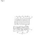
- FIG. 3is a cross-sectional view illustrating exemplary core structures of the power supply device and the power acquisition device in accordance with the first and the second embodiments of the present invention
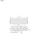
- FIG. 4is a side view showing the exemplary core structure of the power supply device shown in FIG. 3 ;
- FIG. 5is a cross-sectional view describing another exemplary core structure of the power supply device in accordance with the first embodiment of the present invention.
- FIG. 6is a cross-sectional view showing an exemplary power supply device protection cover of the power supply device in accordance with the first embodiment of the present invention
- FIGS. 7 and 9show cross-sectional views of a power acquisition device in accordance with the third embodiment of the present invention.
- FIG. 8schematically describes a side view of the power acquisition device in accordance with the third embodiment of the present invention.
- FIG. 10is a cross-sectional view of a power acquisition device in accordance with the fourth embodiment of the present invention.
- FIG. 11schematically shows a side view of the power acquisition device in accordance with the fourth embodiment of the present invention.
- FIG. 12shows a cross-sectional view of a power acquisition tire in accordance with the fifth embodiment of the present invention.
- FIG. 13is a plan view of a safety system in accordance with the sixth embodiment of the present invention viewed from a road on which an electric vehicle travels;
- FIG. 14is a side view of the safety system depicted in FIG. 13 .
- FIG. 1schematically shows an electromagnetic induction charging system for an electric vehicle in accordance with the present invention.
- the electromagnetic induction charging systemincludes an electromagnetic induction-powered electric vehicle 1 , a power supply device 10 embedded in a road for transferring power, a power acquisition device 20 attached to the electric vehicle for receiving, by magnetic induction, power from the power supply device 10 , an inverter 120 for supplying the power supply device 10 with a high-frequency electric current, a pair of electric vehicle sensors 130 installed at a front end and a back end portions of the power supply device 10 for generating a detection signal for the electric vehicle, batteries 140 for charging electric power thereto and driving the electric vehicle, and an obstacle sensor 150 for detecting an obstacle present in front of the electric vehicle.
- the electromagnetic induction charging system of the present inventionwhen a detection signal is received from the electric vehicle sensors 130 or when an electric power level thus measured is higher than a predetermined reference value, it is determined that there is an electric vehicle present on a road. On the other hand, when no detection signal is received from the electric vehicle sensors and when an electric power level thus measured is lower than the predetermined reference value, it is determined that there is no electric vehicle present on the road.
- the inverter 120applies a high-frequency electric current to a magnetic field generating unit of the power supply device 10 to generate magnetic fields.
- the magnetic fieldsinduce a voltage in a power acquisition coil of the power acquisition device 20 and the batteries 140 are charged with the induced voltage.
- the inverter 120applies no high-frequency electric current to the magnetic field generating unit of the power supply device 10 .
- the batteries 140may be used when the electric vehicle is not on the road when the power supply device 10 is embedded, the capacities of the batteries 140 may be reduced.
- the capacities of the batteries 140may be one fifth of those of the conventional batteries for a conventional battery-type electric vehicle.
- FIG. 2shows a cross-sectional view of a power supply device in accordance with the first embodiment of the present invention.
- a power supply device 10 for transferring poweris embedded in a road and a power acquisition device 20 receives the power from the power supply device 10 by electromagnetic induction.
- a vertical gap Gis formed between the power supply device 10 and the power acquisition device 20 .
- the power supply device 10may extend for a length of 30-300 m in a longitudinal direction of the road.
- the length of the power supply device 10may be modified with any other predetermined length.
- the power supply device 10includes a base plate 11 , a plurality of plate-fixing anchors 12 , a power supply core unit 13 , a magnetic field generating unit 14 , a plurality of magnetic pins 15 , a power supply device protection cover 16 and a grounding wire 17 .
- the base plate 11 having a bended shapeis made of a electrically conductive material, such as steel, and is provided in a hollow cavity that is formed by digging the road below the power supply core unit 13 to support the power supply core unit 13 , the plurality of magnetic pins 15 and the power supply device protection cover 16 , both of which extend along the longitudinal direction of the road.
- the base plate 11is connected to the grounding wire 17 .
- the plurality of plate-fixing anchors 12are provided at a lower surface of the base plate and protrude from the base plate 11 into an inner wall of the hollow cavity to fix the base plate 11 to the road.
- the power supply core unit 13 extending along the longitudinal direction of the roadhas a substantially E-shaped cross section normal to the longitudinal direction of the road and includes a central core portion 13 a , a couple of side core portions 13 b and a base core portion 13 c.
- the central core portion 13 ais disposed at a center portion of the power supply core unit 13 along the longitudinal direction.
- the two side core portions 13 bare disposed at two opposite sides of the power supply core unit 13 along the longitudinal direction of the road. Each of the side core portions 13 b is spaced apart from the central core portion 13 a to have a supply core space therebetween.
- the base core portion 13 cis disposed at a lower portion of the power supply core unit 13 to magnetically connect the central core portion 13 a with the side core portions 13 b.
- the magnetic field generating unit 14 supplied with an alternating electric current from an inverteris disposed in the supply core spaces defined between the central core portion 13 a and the side core portions 13 b , thereby winding around the central core portion 13 a.
- the magnetic pin 15may be made of a composite magnetic material, having a similar wear resistance to that of the material of which the road is made and including a ferrite material, and have a substantially pin-shaped form.
- the power supply device protection cover 16is made of a material having a similar wear resistance to that of the material of which the road is made, such as cement, asphalt, FRP (fiber glass reinforced plastic) and PVC (polyvinyl chloride).
- the power supply device protection cover 16is arranged on the central core portion 13 a , the side core portions 13 b , the supply core spaces between the central core portion 13 a and each of the side core portions 13 b and parts of the base plate 11 to cover them so that they are not exposed over a surface of the road.
- a lower surface of the power supply protection cover 16makes contact with upper surfaces of the central core portion 13 a , the side core portions 13 b and the parts of the base plate 11 .
- An upper surface of the power supply device protection cover 16is substantially coplanar with the surface of the road in such a manner that the power supply device protection cover 16 does not protrude or concave therefrom.
- the power supply protection cover 16includes magnetic portions 16 a arranged on the central core portion 13 a and the side core portions 13 b , throughout which the magnetic pins 15 are distributed, and non-magnetic portions 16 b arranged on the supply core spaces between the central core portion 13 a and each of the side core portions 13 b and the parts of the base plate 11 .
- the magnetic flux flowing from the central core portion 13 a and the side core portions 13 bis efficiently transferred to the power acquisition device 20 through the magnetic portions 16 a .
- the grounding wire 17connects the base plate 11 to the ground so that the base plate 11 is prevented from being electrified due to a deterioration or defect of the magnetic field generating unit 14 .
- FIG. 2also shows a cross sectional view of a power acquisition device in accordance with the second embodiment of the present invention.
- a power acquisition device 20 for receiving power by magnetic inductionis attached to an electromagnetic induction-powered electric vehicle.
- the power acquisition device 20may extend for a length of about 1-2 m in a longitudinal direction of an electric vehicle.
- the length of the power acquisition device 20may be modified with another predetermined length.
- the power acquisition device 20includes a power acquisition core unit 21 , a power acquisition coil 22 , a plurality of magnetic pins 23 and a power acquisition device protection cover 24 .
- the power acquisition core unit 21 extending along the longitudinal direction of the electric vehiclehas a substantially E-shaped cross section normal to the longitudinal direction of the electric vehicle and includes a central core portion 21 a , a couple of side core portions 21 b and a base core portion 21 c.
- the central core portion 21 ais disposed at a center portion of the power acquisition core unit 21 .
- the two side core portions 21 bare disposed at two opposite sides along the longitudinal direction of the electric vehicle. Each of the side core portions 21 b is spaced apart from the central core portion 21 a to have an acquisition core space therebetween.
- the base core portion 21 cis disposed at an upper portion of the power acquisition core unit 21 to magnetically connect the central core portion 21 a with the side core portions 21 b.
- the power acquisition coil 22 connected to batteries of the electric vehicle for chargingare disposed in spaces defined between the central core portion 21 a and the side core portions 21 b , thereby winding around the central core portion 21 a.
- the magnetic pin 23is made of a composite magnetic material including a ferrite material and has a pin-shaped form.
- the power acquisition device protection cover 24is arranged under the central core portion 21 a , the side core portions 21 b and the acquisition core spaces to cover them in such a way that they are not exposed to a surface of the road.
- An upper surface of the power acquisition protection cover 24makes contact with lower surfaces of the central core portion 21 a and the side core portions 21 b.
- the power acquisition device protection cover 24includes magnetic portions 24 a arranged under the central core portion 21 a and the side core portions 21 b , throughout which the magnetic pins 23 are distributed, and non-magnetic portions 24 b arranged under the acquisition core spaces.
- the magnetic flux flowing from the power supply device 10is efficiently transferred to the power acquisition core unit 21 through the magnetic portions 24 a .
- Upper end portions of the magnetic pins 23 stuck into the magnetic portions 24 amake contact with the lower surfaces of the central core portion 21 a and the side core portions 21 b , and lower end portions thereof are substantially coplanar with a lower surface of the power acquisition device protection cover 24 so that the magnetic pins 23 do not protrude or concave from the lower surface of the power acquisition device protection cover 24 .
- FIG. 3is a cross-sectional view illustrating exemplary core structures of the power supply device and the power acquisition device in accordance with the first and the second embodiments of the present invention.
- the central core portion 13 a of the power supply device 10has a width c 3 normal to the longitudinal direction of the road.
- Each of the side core portions 13 b of the power supply device 10 having a width c 1 or c 5 normal to the longitudinal direction of the roadis spaced apart from the central core portion 13 a to have the supply core space therebetween, having a width c 2 or c 4 normal to the longitudinal direction of the road.
- the width c 3 of the central core portion 13 ais set substantially identical to that of c 1 or c 5 of the side core portions 13 b .
- the core width c 1 , c 3 or c 5 of the power supply core unit 13is set substantially identical to the width of c 2 or c 4 of the supply core space.
- the power acquisition device 20may also have the same structure as the equally-spaced core structure of the power supply device 10 described above.
- the output voltagedrops sharply due to an imbalance in the intervals between the cores when a lateral deviation is developed.
- the above equally-spaced core structuremakes it possible to reduce, to certain degrees, the adverse effect of the lateral deviation over the total width c 0 .
- the core widths and the widths of the core spaces therebetweenare set to substantially identical to each other, since the magnetic flux from the central core portion is divided into two side core portions, the quantity of the magnetic flux passing through a cross section of the central core portion parallel to the road surface is twice as great as that passing through a cross section of each of the side core portions parallel to the road surface. This means that, in order to ensure a uniform magnetic-flux density, the area of the cross section of the central core portion through which the magnetic flux passes needs to be twice as great as that of each of the side cores.
- FIG. 4is a side view showing an exemplary core structure of the power supply device in accordance with the first embodiment.
- the central core portion 13 acontinuously extends along the longitudinal direction of the road but each of the side core portions 13 b has segmented core portions and side core spaces therebetween disposed along the longitudinal direction of the road and the lengths of each segmented core portion and each side core space along the longitudinal direction of the road are set substantially identical to each other so that the area of the cross section of the central core portion 13 a , through which the magnetic flux passes, parallel to the surface of the road becomes twice as great as that of each of the side core portions 13 b .
- Non-magnetic support members 33 for supporting a load from the power supply device protection cover 16 and the electric vehicleare inserted into the side core spaces of each of the side core portions 13 b .
- the magnetic flux density in the central core portion 13 ais set substantially identical to that of each of the side core portions 13 b .
- a maximum lateral deviation tolerancebecomes equal to one fifth of a total core width c 0 of the power supply core unit 13 , where the maximum lateral deviation tolerance is defined as the value of a lateral deviation when the measured power transfer efficiency is reduced by 10% compared with that measured under a condition where there is virtually no lateral deviation between the power supply device 10 and the power acquisition device 20 .
- the maximum lateral deviation tolerancebecomes as great as 20 cm in case where the width c 0 of the power supply core unit 13 is equal to 100 cm.
- the power supply core unit 13 and the magnetic field generating unit 14may extend along the road in a sinusoidal wave shape.
- FIG. 5is a cross-sectional view describing another exemplary core structure of the power supply device in accordance with the first embodiment of the present invention.
- the power supply device 10 of a plate structurehas the same configurations as the power supply device 10 illustrated in FIG. 2 except the shapes of the base plate 71 and the core plate 72 , and the presence of an insulating film 75 .
- the base plate 71 provided for supporting the core plate 72 and the magnetic field generating unit 73has a structure of a bended plate shape.
- some parts of the base plate 71 arranged at sides of the magnetic field generating unit 73protrude toward the surface of the road and the other parts of the base plate 71 arranged under the magnetic field generating unit 73 concave from the surface of the road.
- the core plate 72 made of a magnetic materialhas a structure of a bended plate shape.
- the central core portion 72 a and the side core portions 72 b of the core plate 72protrude toward the road surface and the base core portion 72 c of the core plate 72 recesses from the road surface.
- the magnetic field generating unit 73 supplied with alternating electric currentis surrounded by the insulating film 75 .
- the magnetic field generating unit 73 and the insulating film 75are disposed in supply core spaces defined between the central core portion 72 a and the side core portions 72 b to thereby wind around the central core portions 72 a.
- FIG. 6is a cross-sectional view showing an exemplary power supply device protection cover of the power supply device in accordance with the first embodiment of the present invention.
- the protection cover 16is made of a material having a similar wear resistance to that of the material of which the road is made, such as cement, asphalt, FRP (fiber glass reinforced plastic) and PVC (polyvinyl chloride) and a fiber-shaped non-magnetic material 18 (e.g., glass fiber or plastic fiber) having an increased tensile strength.
- a material having a similar wear resistance to that of the material of which the road is madesuch as cement, asphalt, FRP (fiber glass reinforced plastic) and PVC (polyvinyl chloride) and a fiber-shaped non-magnetic material 18 (e.g., glass fiber or plastic fiber) having an increased tensile strength.
- the protection cover 16includes a magnetic composite material portion B and a non-magnetic composite material portion C.
- the magnetic composite material portion Bmay include cement, a magnetic material and a fiber-shaped non-magnetic material; or asphalt, a magnetic material and a non-magnetic reinforcing material.
- the magnetic composite material portion Bhas similar physical properties to those of a general cement-paved or asphalt-paved road except that it can transfer a magnetic flux therethrough.
- the non-magnetic composite material portion Cmay include cement and a fiber-shaped non-magnetic material; or asphalt and a non-magnetic reinforcing material.
- the non-magnetic composite material portion Chas similar physical properties to those of a general cement-paved or asphalt-paved road.
- the fiber-shaped non-magnetic materialis dispersed throughout the power supply protection cover 16 , so that the boundary portion between the magnetic composite material portion and the non-magnetic composite material portion are fixed to each other by the fiber-shaped non-magnetic material.
- the power supply protection cover 16is bonded to the paved road by the bonding force of cement or asphalt. Since the power supply protection cover 16 is made of a material similar to that of the material paving the road, the thermal expansion coefficients of the power supply protection cover 16 and the pavement material of the road are similar to each other. This will help minimize occurrences of cracks and water seepage in the border between the protection cover 16 and the road pavement.
- FIGS. 7 and 9show cross-sectional views of a power acquisition device in accordance with the third embodiment of the present invention.
- the power acquisition device that receives power, for an electric vehicle, from a power supply device embedded in a road by electromagnetic inductionincludes a power acquisition core unit 51 , a power acquisition coil 52 and one or more wheel-shaped rotary magnetic field transfer members 64 or 64 ′.
- the power acquisition core unit 51 extending along a longitudinal direction of the electric vehiclehas a substantially E-shaped cross section normal to the longitudinal direction of the electric vehicle and includes a central core portion 51 a , a couple of side core portions 51 b and a base core portion 51 c.
- the central core portion 51 ais disposed at the center portion of the power acquisition core unit 51 .
- the two side core portions 51 bare disposed at opposite sides of the central core portion 51 a .
- Each of the side core portions 51 bis spaced apart from the central core portion 51 a to have an acquisition core space.
- the base core portion 51 cis disposed at an upper portion of the power acquisition core unit 51 to magnetically connect the central core portion 51 a with the side core portions 51 b.
- the power acquisition coil 52 connected to the batteries of the electric vehicle for chargingis disposed in the acquisition core spaces between the central core portion 51 a and the side core portions 51 b , thereby winding around the central core portion 51 a.
- Each of the wheel-shaped rotary magnetic field transfer members 64 or 64 ′includes a magnetic portion 62 disposed at a central portion thereof and a non-magnetic portion 63 covering a periphery of the magnetic portion 62 .
- the magnetic portion 62is made of a magnetic material including a ferrite material.
- the non-magnetic portion 63is made of a soft material such as a material of the tire including rubber.
- the one or more wheel-shaped rotary magnetic field transfer members 64 or 64 ′are provided below each of the central core portion 51 a and the side core portions 51 b for transferring magnetic fluxes from the power supply device to the power acquisition core unit 51 .
- Each of the wheel-shaped rotary magnetic field transfer members 64may be divided into three parts so that each of the three parts corresponds to the central core portion 51 a or each of the side core portions 51 b.
- each of the wheel-shaped rotary magnetic-field transfer members 64 ′may be consolidated into a single part having three magnetic core portions 62 therein so that each of the magnetic portions 62 corresponds to the central core portion 51 a or one of the side core portions 51 b , respectively, as illustrated in the FIG. 9 .
- FIG. 8schematically describes a side view of the power acquisition device in accordance with the third embodiment of the present invention.
- two or more wheel-type magnetic field transfer members 64 or 64 ′are arranged in a row along the longitudinal direction of the electric vehicle.
- FIGS. 10 and 11are a cross-sectional view and a side view of a power acquisition device in accordance with the fourth embodiment of the present invention.
- a brush-type power acquisition device 100 for an electromagnetic induction-powered electric vehicleincludes a power acquisition core unit 101 , a power acquisition coil 102 and a plurality of magnetic brushes 104 made of a magnetic material including silicon steel or amorphous metal.
- the power acquisition core unit 101 extending along a longitudinal direction of the electric vehiclehas a substantially E-shaped cross section normal to the longitudinal direction of the electric vehicle and includes a central core portion 101 a , a couple of side core portions 101 b and a base core portion 101 c.
- the central core portion 101 ais disposed at a center portion of the power acquisition core unit 101 .
- the two side core portions 101 bare disposed at opposite sides of the central core portion 101 a .
- Each of the side core portions 101 bis spaced apart from the central core portion 101 a to have a supply core space therebetween.
- the base core portion 101 cis disposed at an upper portion of the power acquisition core unit 101 to magnetically connect the central core portion 101 a with the side core portions 101 b.
- the power acquisition coil 102 connected to the batteries of the electric vehicle for chargingis disposed in spaces defined between the central core portion 101 a and the side core portions 101 b , thereby winding the central core portion 101 a.
- the plurality of the magnetic brushes 104are attached to lower end surfaces of the central core portion 101 a and the side core portions 101 b and have predetermined vertical lengths so that they can make contact with a surface of the road.
- Use of the magnetic brushesmakes it possible to minimize a gap between a power supply device and a power acquisition device to thereby increase the power transfer efficiency and reduce the influence of a vertical fluctuating movement of the power acquisition device.
- FIG. 12shows a cross-sectional view of a power acquisition tire in accordance with the fifth embodiment of the present invention.
- the power acquisition tire 110 for functioning as a wheel of an electromagnetic induction-powered electric vehicleincludes a tire 115 having a space thereinside, a power acquisition core unit 111 and a power acquisition coil 112 .
- the power acquisition core unit 111 having a substantially E-shaped cross sectionincludes a central core portion 111 a , a couple of side core portions 111 b and a base core portion 111 c.
- the central core portion 111 ais disposed along a circumferential direction of the tire at a center portion of an inner surface of the tire 115 .
- the side core portions 111 bare disposed along the circumferential direction of the tire at the inner surface of the tire with the central core portion 111 a therebetween.
- the base core portion 111 cis disposed at an opposite side of the inner surface of the tire 115 to magnetically connect the central core portion 101 a with the side core portions 101 b.
- the power acquisition core unit 111is preferably made of a pliable material that can be deformed in concert with the deformation of the tire.
- the power acquisition coil 112 connected to the batteries of the electric vehicle for chargingis disposed along spaces surrounded by the central core portion 111 a , each of the side core portions 111 b and the base core portion 111 c.
- Use of the power acquisition tiremay prevent the power acquisition device from colliding with an obstacle present on the road, while minimizing a gap between a power supply device and a power acquisition tire.
- FIGS. 13 and 14are a plan view of a safety system in accordance with the sixth embodiment of the present invention viewed from a road on which an electromagnetic induction-powered electric vehicle travels and a side view thereof.
- the safety system 155 for the power acquisition device 210includes an obstacle sensor 150 , a supporting member 190 , a link member 160 , a lifting unit 215 , a shock absorber 180 , a protection plate 170 and two pairs of auxiliary safety wheels 200 .
- the obstacle sensor 150is provided at a front side of the electric vehicle 1 and detects an obstacle 220 present in front of the electric vehicle to generate a detection signal.
- the supporting member 190mounts the power acquisition device 210 onto a bottom surface thereof.
- the link member 160connects a bottom surface of the electric vehicle 1 with the supporting member 190 .
- one end portion of the link member 160is hingedly connected to the bottom surface of the electric vehicle 1 so that the link member 160 can pivotally move about a hinge axis A 1 in a back-and-forth direction within a plane perpendicular to a road surface.
- the other end portion of the link member 160is hingedly connected to the supporting member 190 .
- the lifting unit 215connects the link member 160 with the bottom surface of the electric vehicle 1 to rotate the link member 160 .
- the lifting unit 215may be an electric motor or a hydraulic cylinder.
- the shock absorber 180is attached to a front end portion of the dsupport member 190 to absorb shock generated by a collision between the obstacle 220 and the protection plate 170 .
- the protection plate 170is attached to a front end portion of the shock absorber 180 to extend obliquely with respect to a longitudinal direction of the electric vehicle. When colliding with the obstacle 220 , the protection plate 170 pushes the obstacle 220 laterally outwards.
- the above safety systemoperates as explained below.
- the link member 160is rotated upwardly about the hinge axis A 1 by the lifting unit 215 to lift up the device support member 190 .
- the link member 160is rotated upwardly about the hinge axis A 1 by shock not absorbed by the shock absorber to lift up the support member 190 . Since the link member 160 is hingedly connected to the supporting member 190 , it is possible to keep the supporting member 190 from inclining even though the supporting member 190 is lifted upwardly by the link member 160 .
- the power acquisition devicemay be prevented from colliding with the obstacle present on the road.
- Two pairs of auxiliary safety wheels 200are arranged at the bottom surface of the support member 190 .
- One pair of wheelsare arranged at the front end portion of the supporting member 190 and the other pair of wheels are arranged at the back end portion thereof.
- the diameter of the safety wheel 200is made to be larger than the width in the vertical direction of the acquisition device 210 .
- the magnetic brushes of the fourth embodiment illustrated in FIG. 10may be applied to the power acquisition device in accordance with the second embodiment of the present invention.
- the power supply device in accordance with the first embodiment and the power acquisition device in accordance with one of the remaining embodiments of the present inventionmay be included in an electromagnetic induction charging system.
- the present inventionoffers a number of critical advantages.
- the batteries employed in an electric vehicleare charged while it is moving along a road provided with the inventive power supply device. Needless to say, this makes it possible to avoid or minimize any battery charging time. Further, it is capable of reducing the capacities of the batteries and extending the lifespan thereof.
- the power transfer efficiencyis greatly increased compared with that of the conventional electromagnetic induction charging system by maximizing a lateral deviation tolerance and by minimizing a vertical gap between the primary and the second coils.
Landscapes
- Engineering & Computer Science (AREA)
- Power Engineering (AREA)
- Mechanical Engineering (AREA)
- Transportation (AREA)
- Sustainable Energy (AREA)
- Life Sciences & Earth Sciences (AREA)
- Sustainable Development (AREA)
- Computer Networks & Wireless Communication (AREA)
- Physics & Mathematics (AREA)
- Electromagnetism (AREA)
- Current-Collector Devices For Electrically Propelled Vehicles (AREA)
- Electric Propulsion And Braking For Vehicles (AREA)
- Charge And Discharge Circuits For Batteries Or The Like (AREA)
Abstract
Description
c1=c2=c3=c4=c5=d1=d2=d3=d4=d5.
Claims (22)
Applications Claiming Priority (5)
| Application Number | Priority Date | Filing Date | Title |
|---|---|---|---|
| KR10-2009-0016573 | 2009-02-27 | ||
| KR20090016573 | 2009-02-27 | ||
| KR10-2009-0067715 | 2009-07-24 | ||
| KR1020090067715AKR100944113B1 (en) | 2009-02-27 | 2009-07-24 | Power supply system and method for electric vehicles |
| PCT/KR2010/000856WO2010098547A2 (en) | 2009-02-27 | 2010-02-11 | Power supply device, power acquisition device and safety system for electromagnetic induction-powered electric vehicle |
Publications (2)
| Publication Number | Publication Date |
|---|---|
| US20120186927A1 US20120186927A1 (en) | 2012-07-26 |
| US8807308B2true US8807308B2 (en) | 2014-08-19 |
Family
ID=42083756
Family Applications (1)
| Application Number | Title | Priority Date | Filing Date |
|---|---|---|---|
| US13/202,753Active - Reinstated2031-04-08US8807308B2 (en) | 2009-02-27 | 2010-02-11 | Power supply device, power acquisition device and safety system for electromagnetic induction-powered electric vehicle |
Country Status (9)
| Country | Link |
|---|---|
| US (1) | US8807308B2 (en) |
| EP (1) | EP2401171A2 (en) |
| JP (1) | JP2012519104A (en) |
| KR (1) | KR100944113B1 (en) |
| CN (1) | CN102333668A (en) |
| BR (1) | BRPI1008309A2 (en) |
| SG (1) | SG173861A1 (en) |
| TW (1) | TW201040049A (en) |
| WO (1) | WO2010098547A2 (en) |
Cited By (11)
| Publication number | Priority date | Publication date | Assignee | Title |
|---|---|---|---|---|
| US20140239890A1 (en)* | 2013-02-27 | 2014-08-28 | Satyajit Patwardhan | Hands free conductive charging system for Electric Vehicles |
| US20150136499A1 (en)* | 2012-05-09 | 2015-05-21 | Toyota Jidosha Kabushiki Kaisha | Vehicle |
| US20160114687A1 (en)* | 2013-04-26 | 2016-04-28 | Toyota Jidosha Kabushiki Kaisha | Power receiving device, power transmitting device, power transfer system, and parking assisting device |
| US20170136907A1 (en)* | 2015-11-13 | 2017-05-18 | NextEv USA, Inc. | Electric vehicle charging device alignment and method of use |
| US9800092B2 (en) | 2012-07-26 | 2017-10-24 | Ihi Corporation | Wireless power-supplying system |
| US9944192B2 (en) | 2015-11-13 | 2018-04-17 | Nio Usa, Inc. | Electric vehicle charging station system and method of use |
| US10093195B2 (en) | 2015-11-13 | 2018-10-09 | Nio Usa, Inc. | Integrated vehicle charging panel system and method of use |
| US10124690B2 (en) | 2015-11-13 | 2018-11-13 | Nio Usa, Inc. | Electric vehicle charging device positioning and method of use |
| US10604020B2 (en) | 2015-11-13 | 2020-03-31 | Nio Usa, Inc. | Floating armature |
| US20220242256A1 (en)* | 2020-08-18 | 2022-08-04 | Green Power Co., Ltd. | Wireless charging system |
| US20230202304A1 (en)* | 2020-06-01 | 2023-06-29 | Elonroad Ab | A contact member for collecting power from an electric road track |
Families Citing this family (77)
| Publication number | Priority date | Publication date | Assignee | Title |
|---|---|---|---|---|
| KR100944113B1 (en)* | 2009-02-27 | 2010-02-24 | 한국과학기술원 | Power supply system and method for electric vehicles |
| KR101040662B1 (en)* | 2009-04-06 | 2011-06-13 | 한국과학기술원 | Ultra slim power supply and collector device for electric vehicle |
| GB2477080A (en)* | 2009-12-21 | 2011-07-27 | Bombardier Transp Gmbh | Modular track for vehicle using inductive energy transfer |
| JP5431297B2 (en)* | 2009-12-24 | 2014-03-05 | ラスク・インテレクチュアル・リザーブ・アクチェンゲゼルシャフト | Electric vehicle and its power supply equipment |
| KR101124575B1 (en)* | 2009-12-29 | 2012-03-16 | 한국과학기술원 | Magenetic Field Cancellation apparatus for OLEV |
| US8556050B2 (en)* | 2010-03-25 | 2013-10-15 | Bryan Richards | Electrical connection device for electric vehicles |
| KR101124606B1 (en)* | 2010-06-03 | 2012-03-20 | 한국과학기술원 | Cross-type segment power supply |
| KR101169035B1 (en)* | 2010-07-09 | 2012-07-27 | 한국과학기술원 | Collector device for electric vehicle with active cancellation of emf |
| KR101156034B1 (en)* | 2010-07-15 | 2012-06-18 | 한국과학기술원 | Method and device for designing power supply device of transportation system using electric vehicle |
| KR101210436B1 (en)* | 2010-07-26 | 2012-12-10 | 현대로템 주식회사 | Contactless power supply apparatus |
| KR101201292B1 (en)* | 2010-08-16 | 2012-11-14 | 한국과학기술원 | Magnetic Inductive Power Transfer Apparatus and Moving Object Using the Same |
| KR101179468B1 (en) | 2010-08-25 | 2012-09-10 | 한국과학기술원 | Collector device for electric vehicle |
| KR101232036B1 (en)* | 2010-10-13 | 2013-02-12 | 한국과학기술원 | Non-contact power transmission device and self-induction power feeding device |
| GB2485616A (en)* | 2010-11-22 | 2012-05-23 | Bombardier Transp Gmbh | Route for transferring electric energy to vehicles |
| JP5818431B2 (en) | 2010-12-21 | 2015-11-18 | 東海旅客鉄道株式会社 | Transformer |
| KR101242740B1 (en)* | 2011-01-14 | 2013-03-12 | 한국과학기술원 | Automatically controlled EMF cancellation apparatus using reverse current with current sensor |
| WO2012116054A2 (en)* | 2011-02-22 | 2012-08-30 | Steele Daniel W | Wireless automated vehicle energizing system |
| KR101226525B1 (en)* | 2011-04-13 | 2013-01-25 | 한국과학기술원 | Ferrite core structure for power supply device of electric vehicle and road structure using thereof |
| KR101182376B1 (en)* | 2011-04-26 | 2012-09-12 | 한국과학기술원 | Magnetic Inductive Apparatus for Power Transmission, Power Collection and Power Transmission Considering Horizontal Deviation |
| US20120319644A1 (en)* | 2011-06-15 | 2012-12-20 | Chih-Kuei Hu | Contactless charging system |
| KR101242735B1 (en) | 2011-08-19 | 2013-03-13 | 한국과학기술원 | Magnetic field cancellation material, power supply and pickup device using the material |
| KR101796022B1 (en) | 2011-08-30 | 2017-11-13 | 한국과학기술원 | 24V car battery charging device |
| EP2751900B1 (en)* | 2011-09-07 | 2021-08-04 | Auckland UniServices Limited | Magnetic field shaping for inductive power transfer |
| JP5803475B2 (en)* | 2011-09-16 | 2015-11-04 | 株式会社Ihi | Mobile vehicle power supply system |
| SG11201400970YA (en)* | 2011-09-26 | 2014-09-26 | Korea Advanced Inst Sci & Tech | Power supply and pickup system capable of maintaining stability of transmission efficiency despite changes in resonant frequency |
| KR101364185B1 (en) | 2011-09-26 | 2014-02-20 | 한국과학기술원 | Loop type emf shielding apparatus |
| GB2496433A (en)* | 2011-11-10 | 2013-05-15 | Bombardier Transp Gmbh | Inductively transferring energy to an electric vehicle |
| KR101306873B1 (en)* | 2011-11-15 | 2013-09-10 | 한국과학기술원 | Power supply line system for high speed railroad |
| DE102012103315B4 (en)* | 2012-04-17 | 2014-03-27 | Conductix-Wampfler Gmbh | Coil unit and electric vehicle with such |
| GB2501482A (en) | 2012-04-23 | 2013-10-30 | Bombardier Transp Gmbh | Providing a land vehicle with electric energy by magnetic induction |
| WO2013162431A1 (en)* | 2012-04-23 | 2013-10-31 | Telefonaktiebolaget L M Ericsson (Publ) | Charging of vehicles on a road |
| GB2505149A (en)* | 2012-05-11 | 2014-02-26 | Bombardier Transp Gmbh | Inductive pick-up arrangement for an electric vehicle |
| GB2502084A (en) | 2012-05-14 | 2013-11-20 | Bombardier Transp Gmbh | Arrangement for providing vehicles with energy comprising magnetisable material |
| KR101298223B1 (en) | 2012-06-01 | 2013-08-22 | 김현민 | Wireless charging system for electric car and charging method therefor |
| GB2503484A (en)* | 2012-06-27 | 2014-01-01 | Bombardier Transp Gmbh | Inductive vehicle charging station and method with lateral electromagnetic shielding |
| JP5938288B2 (en)* | 2012-07-19 | 2016-06-22 | 株式会社日立パワーソリューションズ | Wireless power feeder |
| GB2505006A (en)* | 2012-08-17 | 2014-02-19 | Bombardier Transp Gmbh | Inductive pick-up arrangement for an electric vehicle |
| JP6086189B2 (en)* | 2012-09-05 | 2017-03-01 | Tdk株式会社 | Coil device |
| JP6068885B2 (en)* | 2012-09-10 | 2017-01-25 | Ihi運搬機械株式会社 | Vehicle power supply device |
| JP5716725B2 (en)* | 2012-11-21 | 2015-05-13 | トヨタ自動車株式会社 | Power transmission device and power transmission system |
| US10164503B2 (en)* | 2013-01-23 | 2018-12-25 | Hyeon Cheol Moon | Power generation system using vehicle |
| CN103112356A (en)* | 2013-01-28 | 2013-05-22 | 中国民航大学 | Device for improving electric automobile contactless power transfer efficiency |
| JP5374657B1 (en) | 2013-03-21 | 2013-12-25 | 東亜道路工業株式会社 | Pavement structure and construction method of pavement structure |
| JP5374658B1 (en) | 2013-03-21 | 2013-12-25 | 東亜道路工業株式会社 | Trough, pavement structure, and pavement structure construction method |
| JP6130186B2 (en)* | 2013-03-28 | 2017-05-17 | 株式会社リューテック | Electric vehicle power supply system |
| WO2014178589A1 (en)* | 2013-05-02 | 2014-11-06 | Park Chan Woong | Magnetic energy transfer device and power supply unit |
| US10396596B2 (en) | 2013-11-13 | 2019-08-27 | Apple Inc. | Transmitter for inductive power transfer systems |
| GB2524734A (en)* | 2014-03-31 | 2015-10-07 | Bombardier Transp Gmbh | Receiving device, vehicle and method of manufacturing a receiving device |
| EP3146542A4 (en) | 2014-05-19 | 2017-06-14 | PowerbyProxi Limited | Magnetically permeable core and inductive power transfer coil arrangement |
| WO2015178781A1 (en) | 2014-05-19 | 2015-11-26 | Powerbyproxi Limited | Magnetically permeable core and an inductive power transfer coil arrangement |
| GB2526307A (en)* | 2014-05-20 | 2015-11-25 | Bombardier Transp Gmbh | A housing for at least one object detection device, a primary unit and a pavement slab assembly |
| EP3180835A4 (en) | 2014-08-12 | 2017-09-13 | PowerbyProxi Limited | System and method for power transfer |
| KR20160021332A (en)* | 2014-08-14 | 2016-02-25 | 현대자동차주식회사 | Method for controlling wireless charging device |
| CN104333145A (en)* | 2014-10-18 | 2015-02-04 | 刘跃进 | Electric vehicle-used rechargeable tire and tire-type wireless charging belt system |
| SE538795C2 (en) | 2015-03-04 | 2016-11-29 | Scania Cv Ab | Motor Vehicle and Method of Detecting Obstacles in the Way of an Electric Power Supply Unit |
| KR101627798B1 (en)* | 2015-11-04 | 2016-06-13 | (주)그린파워 | Wireless charging electric vehicle and method thereof |
| US10427530B2 (en) | 2015-11-13 | 2019-10-01 | Nio Usa, Inc. | Vehicle charge query and exchange system and method of use |
| US10220717B2 (en) | 2015-11-13 | 2019-03-05 | Nio Usa, Inc. | Electric vehicle emergency charging system and method of use |
| JP6768806B2 (en)* | 2015-12-18 | 2020-10-14 | ボルボトラックコーポレーション | How to control a vehicle safety system that uses an electric road system |
| US20170297437A1 (en)* | 2016-04-19 | 2017-10-19 | Faraday&Future Inc. | Charging connection for an electric vehicle |
| US10377255B2 (en)* | 2016-05-13 | 2019-08-13 | Witricity Corporation | Methods and apparatus for reducing flux cancellation in ferrite of double couple inductive power transfer systems |
| WO2017204663A1 (en) | 2016-05-25 | 2017-11-30 | Powerbyproxi Limited | A coil arrangement |
| WO2017209630A1 (en) | 2016-06-01 | 2017-12-07 | Powerbyproxi Limited | A powered joint with wireless transfer |
| CN206834025U (en) | 2016-11-18 | 2018-01-02 | 鲍尔拜普罗克西有限公司 | Induction type power transmission line coil assembly |
| US10515390B2 (en)* | 2016-11-21 | 2019-12-24 | Nio Usa, Inc. | Method and system for data optimization |
| US10978911B2 (en) | 2016-12-19 | 2021-04-13 | Apple Inc. | Inductive power transfer system |
| FR3065405B1 (en) | 2017-04-25 | 2021-02-12 | Alstom Transp Tech | ELASTOMERIC CONDUCTIVE TRACK SUPPORT WITH RECTANGULAR SECTION FOR GROUND ELECTRICAL SUPPLY SYSTEM |
| CN110014896B (en)* | 2017-10-20 | 2022-02-08 | 鸿海精密工业股份有限公司 | Wireless charging automobile and wireless charging road |
| US10593468B2 (en) | 2018-04-05 | 2020-03-17 | Apple Inc. | Inductive power transfer assembly |
| JP7087664B2 (en) | 2018-05-17 | 2022-06-21 | 株式会社Ihi | Coil device |
| JP7014081B2 (en)* | 2018-07-30 | 2022-02-01 | トヨタ自動車株式会社 | Charger |
| TWI687946B (en)* | 2019-04-16 | 2020-03-11 | 致伸科技股份有限公司 | Wireless charging device and transmitting module and transmitting coil thereof |
| JP7365804B2 (en)* | 2019-07-25 | 2023-10-20 | 株式会社ブリヂストン | Wireless power receiving system, tire/wheel assembly, and tire |
| JP7557977B2 (en)* | 2020-07-01 | 2024-09-30 | 株式会社大林組 | Embedded structure of coil for non-contact power supply |
| KR102815620B1 (en)* | 2022-08-12 | 2025-06-04 | 울산과학기술원 | Double-Track Self-Grounding Wireless Charging Method and System for Charging Electric Vehicles While Driving |
| KR20240127067A (en) | 2023-02-15 | 2024-08-22 | 국립공주대학교 산학협력단 | Power supply system and method for electric vehicle |
| FR3159933A1 (en)* | 2024-03-07 | 2025-09-12 | Valeo Eautomotive Germany Gmbh | Component for contactless exchange of electrical energy by inductive coupling |
Citations (27)
| Publication number | Priority date | Publication date | Assignee | Title |
|---|---|---|---|---|
| US4476947A (en)* | 1981-06-26 | 1984-10-16 | Chevron Research Company | Electric car and roadway system |
| US4836344A (en)* | 1987-05-08 | 1989-06-06 | Inductran Corporation | Roadway power and control system for inductively coupled transportation system |
| US5045646A (en)* | 1989-07-20 | 1991-09-03 | Musachio Nicholas R | Electrical vehicle transportation system |
| US5134254A (en)* | 1989-07-20 | 1992-07-28 | Musachio Nicholas R | Electrical vehicle transportation system |
| JPH06245326A (en) | 1993-02-19 | 1994-09-02 | Fujitsu Denso Ltd | Communication control system for electric automobile |
| US5595271A (en)* | 1995-08-07 | 1997-01-21 | Tseng; Ling-Yuan | Electric vehicle pick-up position control |
| US6101952A (en)* | 1997-12-24 | 2000-08-15 | Magnemotion, Inc. | Vehicle guidance and switching via magnetic forces |
| US6471020B1 (en)* | 2000-04-01 | 2002-10-29 | Jose A. L. Hernandez | Electrical current generating/distribution system for electric vehicles |
| US20030200025A1 (en)* | 1994-05-05 | 2003-10-23 | H R Ross Industries, Inc., A California Corporatio | Roadway-powered electric vehicle system having automatic guidance and demand-based dispatch features |
| KR20050106313A (en) | 2004-05-04 | 2005-11-09 | 한국철도기술연구원 | The electric car battery charging system using non contact supply electric power |
| US20070131505A1 (en)* | 2005-07-16 | 2007-06-14 | Kim Bryan H J | Magnetic Induction Charging System for Vehicles |
| WO2007108586A1 (en) | 2006-03-22 | 2007-09-27 | Korea Railroad Research Institute | System of railway vehicle using linear motor and non-contact electric power supply system |
| US20080129246A1 (en)* | 2006-11-10 | 2008-06-05 | Mitsubishi Heavy Industries, Ltd. | Non-contact type power feeder system for mobile object and protecting apparatus thereof |
| US7611212B2 (en) | 2004-12-24 | 2009-11-03 | Honda Motor Co., Ltd. | Motorcycle braking device and related control method |
| US7825537B2 (en)* | 2008-11-14 | 2010-11-02 | Harris Corporation | Inductive power transfer system and method |
| US20110163542A1 (en)* | 2006-10-25 | 2011-07-07 | Laszlo Farkas | High power wireless resonant energy transfer system |
| US20110259694A1 (en)* | 2009-03-12 | 2011-10-27 | Toyota Jidosha Kabushiki Kaisha | Electrically powered vehicle |
| US20110315496A1 (en)* | 2010-06-24 | 2011-12-29 | General Electric Company | Power transfer system and method |
| US8113310B2 (en)* | 2009-02-12 | 2012-02-14 | General Atomics | Linear motor charged electric vehicle |
| US20120055751A1 (en)* | 2008-09-19 | 2012-03-08 | Bombardier Transportation Gmbh | Inductively receiving electric energy for a vehicle |
| US20120103741A1 (en)* | 2009-04-06 | 2012-05-03 | Korean Advanced Institute Of Science And Technology | Ultra slim power supply device and power acquisition device for electric vehicle |
| US8220568B2 (en)* | 2011-05-19 | 2012-07-17 | Blue Wheel Technologies, Inc. | Systems and methods for powering a vehicle |
| US20120186927A1 (en)* | 2009-02-27 | 2012-07-26 | Korea Advanced Institute Of Science And Technology | Power Supply Device, Power Acquisition Device and Safety System for Electromagnetic Induction-Powered Electric Vehicle |
| US8240406B2 (en)* | 2010-07-15 | 2012-08-14 | Blue Wheel Technologies, Inc. | Systems and methods for powering a vehicle, and generating and distributing energy |
| US8360216B2 (en)* | 2008-07-04 | 2013-01-29 | Bombardier Transportation Gmbh | System and method for transferring electric energy to a vehicle |
| US20130037367A1 (en)* | 2011-08-12 | 2013-02-14 | Jorge Aguilar | Electric vehicle and roadway power system therefore |
| US20130037365A1 (en)* | 2010-03-16 | 2013-02-14 | Toyota Jidosha Kabushiki Kaisha | Inductively charged vehicle with automatic positioning |
Family Cites Families (5)
| Publication number | Priority date | Publication date | Assignee | Title |
|---|---|---|---|---|
| JPH0767206A (en)* | 1993-08-26 | 1995-03-10 | Sumitomo Electric Ind Ltd | Non-contact intermittent power supply device for mobile |
| JPH1154349A (en)* | 1997-06-06 | 1999-02-26 | Shinko Electric Co Ltd | Non-contact feeding device |
| JP2001177916A (en)* | 1999-12-10 | 2001-06-29 | Toyota Motor Corp | Energy-supplying apparatus |
| JP4356844B2 (en)* | 2006-10-05 | 2009-11-04 | 昭和飛行機工業株式会社 | Non-contact power feeding device |
| KR100875945B1 (en)* | 2007-02-05 | 2008-12-26 | 한국철도기술연구원 | Railway Vehicle System Using Optimum Airflow Control Linear Motor and Non-Contact Feeding System |
- 2009
- 2009-07-24KRKR1020090067715Apatent/KR100944113B1/enactiveActive
- 2010
- 2010-02-11JPJP2011551975Apatent/JP2012519104A/enactivePending
- 2010-02-11BRBRPI1008309Apatent/BRPI1008309A2/ennot_activeIP Right Cessation
- 2010-02-11USUS13/202,753patent/US8807308B2/enactiveActive - Reinstated
- 2010-02-11CNCN2010800097011Apatent/CN102333668A/enactivePending
- 2010-02-11WOPCT/KR2010/000856patent/WO2010098547A2/enactiveApplication Filing
- 2010-02-11SGSG2011061611Apatent/SG173861A1/enunknown
- 2010-02-11EPEP10746386Apatent/EP2401171A2/ennot_activeWithdrawn
- 2010-02-25TWTW099105453Apatent/TW201040049A/enunknown
Patent Citations (32)
| Publication number | Priority date | Publication date | Assignee | Title |
|---|---|---|---|---|
| US4476947A (en)* | 1981-06-26 | 1984-10-16 | Chevron Research Company | Electric car and roadway system |
| US4836344A (en)* | 1987-05-08 | 1989-06-06 | Inductran Corporation | Roadway power and control system for inductively coupled transportation system |
| US5045646A (en)* | 1989-07-20 | 1991-09-03 | Musachio Nicholas R | Electrical vehicle transportation system |
| US5134254A (en)* | 1989-07-20 | 1992-07-28 | Musachio Nicholas R | Electrical vehicle transportation system |
| JPH06245326A (en) | 1993-02-19 | 1994-09-02 | Fujitsu Denso Ltd | Communication control system for electric automobile |
| US20030200025A1 (en)* | 1994-05-05 | 2003-10-23 | H R Ross Industries, Inc., A California Corporatio | Roadway-powered electric vehicle system having automatic guidance and demand-based dispatch features |
| US6879889B2 (en)* | 1994-05-05 | 2005-04-12 | H.R. Ross Industries, Inc. | Roadway-powered electric vehicle system having automatic guidance and demand-based dispatch features |
| US20050178632A1 (en)* | 1994-05-05 | 2005-08-18 | Ross Howard R. | Roadway-powered electric vehicle system having automatic guidance and demand-based dispatch features |
| US5595271A (en)* | 1995-08-07 | 1997-01-21 | Tseng; Ling-Yuan | Electric vehicle pick-up position control |
| US6101952A (en)* | 1997-12-24 | 2000-08-15 | Magnemotion, Inc. | Vehicle guidance and switching via magnetic forces |
| US6471020B1 (en)* | 2000-04-01 | 2002-10-29 | Jose A. L. Hernandez | Electrical current generating/distribution system for electric vehicles |
| KR20050106313A (en) | 2004-05-04 | 2005-11-09 | 한국철도기술연구원 | The electric car battery charging system using non contact supply electric power |
| US7611212B2 (en) | 2004-12-24 | 2009-11-03 | Honda Motor Co., Ltd. | Motorcycle braking device and related control method |
| US20070131505A1 (en)* | 2005-07-16 | 2007-06-14 | Kim Bryan H J | Magnetic Induction Charging System for Vehicles |
| WO2007108586A1 (en) | 2006-03-22 | 2007-09-27 | Korea Railroad Research Institute | System of railway vehicle using linear motor and non-contact electric power supply system |
| KR100840927B1 (en) | 2006-03-22 | 2008-06-24 | 한국철도기술연구원 | Railway vehicle system using linear motor and non-contact power feeding system |
| US20110163542A1 (en)* | 2006-10-25 | 2011-07-07 | Laszlo Farkas | High power wireless resonant energy transfer system |
| US20080129246A1 (en)* | 2006-11-10 | 2008-06-05 | Mitsubishi Heavy Industries, Ltd. | Non-contact type power feeder system for mobile object and protecting apparatus thereof |
| US8360216B2 (en)* | 2008-07-04 | 2013-01-29 | Bombardier Transportation Gmbh | System and method for transferring electric energy to a vehicle |
| US20120055751A1 (en)* | 2008-09-19 | 2012-03-08 | Bombardier Transportation Gmbh | Inductively receiving electric energy for a vehicle |
| US7825537B2 (en)* | 2008-11-14 | 2010-11-02 | Harris Corporation | Inductive power transfer system and method |
| US8113310B2 (en)* | 2009-02-12 | 2012-02-14 | General Atomics | Linear motor charged electric vehicle |
| US20120186927A1 (en)* | 2009-02-27 | 2012-07-26 | Korea Advanced Institute Of Science And Technology | Power Supply Device, Power Acquisition Device and Safety System for Electromagnetic Induction-Powered Electric Vehicle |
| US20110259694A1 (en)* | 2009-03-12 | 2011-10-27 | Toyota Jidosha Kabushiki Kaisha | Electrically powered vehicle |
| US20120103741A1 (en)* | 2009-04-06 | 2012-05-03 | Korean Advanced Institute Of Science And Technology | Ultra slim power supply device and power acquisition device for electric vehicle |
| US20130037365A1 (en)* | 2010-03-16 | 2013-02-14 | Toyota Jidosha Kabushiki Kaisha | Inductively charged vehicle with automatic positioning |
| US20110315496A1 (en)* | 2010-06-24 | 2011-12-29 | General Electric Company | Power transfer system and method |
| US8240406B2 (en)* | 2010-07-15 | 2012-08-14 | Blue Wheel Technologies, Inc. | Systems and methods for powering a vehicle, and generating and distributing energy |
| US8561770B2 (en)* | 2010-07-15 | 2013-10-22 | Blue Wheel Technologies, Inc. | Systems and methods for distributing energy in a roadway |
| US8220568B2 (en)* | 2011-05-19 | 2012-07-17 | Blue Wheel Technologies, Inc. | Systems and methods for powering a vehicle |
| US20130037367A1 (en)* | 2011-08-12 | 2013-02-14 | Jorge Aguilar | Electric vehicle and roadway power system therefore |
| US8418824B2 (en)* | 2011-08-12 | 2013-04-16 | Jorge Aguilar | Electric vehicle and roadway power system therefore |
Non-Patent Citations (1)
| Title |
|---|
| International Search Report for PCT/KR2010/000856 mailed Sep. 17, 2010. |
Cited By (19)
| Publication number | Priority date | Publication date | Assignee | Title |
|---|---|---|---|---|
| US20150136499A1 (en)* | 2012-05-09 | 2015-05-21 | Toyota Jidosha Kabushiki Kaisha | Vehicle |
| US10960770B2 (en) | 2012-05-09 | 2021-03-30 | Toyota Jidosha Kabushiki Kaisha | Vehicle |
| US9800092B2 (en) | 2012-07-26 | 2017-10-24 | Ihi Corporation | Wireless power-supplying system |
| US9586493B2 (en)* | 2013-02-27 | 2017-03-07 | Satyajit Patwardhan | Hands free conductive charging system for electric vehicles |
| US20140239890A1 (en)* | 2013-02-27 | 2014-08-28 | Satyajit Patwardhan | Hands free conductive charging system for Electric Vehicles |
| US9643505B2 (en)* | 2013-04-26 | 2017-05-09 | Toyota Jidosha Kabushiki Kaisha | Power receiving device, power transmitting device, power transfer system, and parking assisting device |
| US20160114687A1 (en)* | 2013-04-26 | 2016-04-28 | Toyota Jidosha Kabushiki Kaisha | Power receiving device, power transmitting device, power transfer system, and parking assisting device |
| US9944192B2 (en) | 2015-11-13 | 2018-04-17 | Nio Usa, Inc. | Electric vehicle charging station system and method of use |
| US20170136907A1 (en)* | 2015-11-13 | 2017-05-18 | NextEv USA, Inc. | Electric vehicle charging device alignment and method of use |
| US20170136880A1 (en)* | 2015-11-13 | 2017-05-18 | NextEv USA, Inc. | Electric vehicle charging device obstacle avoidance and warning system and method of use |
| US10093195B2 (en) | 2015-11-13 | 2018-10-09 | Nio Usa, Inc. | Integrated vehicle charging panel system and method of use |
| US10124690B2 (en) | 2015-11-13 | 2018-11-13 | Nio Usa, Inc. | Electric vehicle charging device positioning and method of use |
| US10189363B2 (en) | 2015-11-13 | 2019-01-29 | Nio Usa, Inc. | Electric vehicle roadway charging system and method of use |
| US10336194B2 (en)* | 2015-11-13 | 2019-07-02 | Nio Usa, Inc. | Electric vehicle charging device alignment and method of use |
| US10604020B2 (en) | 2015-11-13 | 2020-03-31 | Nio Usa, Inc. | Floating armature |
| US9694685B2 (en)* | 2015-11-13 | 2017-07-04 | NextEv USA, Inc. | Electric vehicle charging device obstacle avoidance and warning system and method of use |
| US20230202304A1 (en)* | 2020-06-01 | 2023-06-29 | Elonroad Ab | A contact member for collecting power from an electric road track |
| US20220242256A1 (en)* | 2020-08-18 | 2022-08-04 | Green Power Co., Ltd. | Wireless charging system |
| US12263742B2 (en)* | 2020-08-18 | 2025-04-01 | Green Power Co., Ltd. | Wireless charging system |
Also Published As
| Publication number | Publication date |
|---|---|
| BRPI1008309A2 (en) | 2016-02-23 |
| SG173861A1 (en) | 2011-09-29 |
| EP2401171A2 (en) | 2012-01-04 |
| KR100944113B1 (en) | 2010-02-24 |
| US20120186927A1 (en) | 2012-07-26 |
| WO2010098547A3 (en) | 2010-11-18 |
| TW201040049A (en) | 2010-11-16 |
| CN102333668A (en) | 2012-01-25 |
| JP2012519104A (en) | 2012-08-23 |
| WO2010098547A2 (en) | 2010-09-02 |
Similar Documents
| Publication | Publication Date | Title |
|---|---|---|
| US8807308B2 (en) | Power supply device, power acquisition device and safety system for electromagnetic induction-powered electric vehicle | |
| US20120103741A1 (en) | Ultra slim power supply device and power acquisition device for electric vehicle | |
| KR101930601B1 (en) | Arrangement, system and a method for a vehicle with electric energy | |
| JP2010022183A (en) | Electric vehicle and inductive power-transmission device suitable therefor | |
| KR101835914B1 (en) | Transferring electric energy to a vehicle by induction | |
| US4007817A (en) | Roadway for supplying power to vehicles and method of using the same | |
| AU2010335485B2 (en) | Track for a track bound vehicle | |
| CN102257698B (en) | Device for transmitting electrical energy | |
| RU2619626C2 (en) | Block of road pavement plate and method of manufacturing road pavement plate | |
| ES2423059T3 (en) | Positioning and / or fixation of a series of power line sections along the path of a vehicle | |
| JP2018079932A (en) | Roadway powered electric vehicle system | |
| US9796272B2 (en) | Road bearing for electric vehicle connection | |
| CN110014896A (en) | A wireless charging car and wireless charging road | |
| CN108462355A (en) | Electromagnetic vibration energy collector for Bridges on Urban Rail Transit health monitoring | |
| KR20130137006A (en) | Route for vehicles and method of building the route | |
| JP2015044422A (en) | Trough, pavement structure and construction method of pavement structure | |
| CN105186707B (en) | Track equipment applied to the hollow T-shaped power supply rail of electric automobile wireless power and containing the power supply rail | |
| KR101325551B1 (en) | wireless charging apparatus | |
| Choi et al. | Trends of wireless power transfer systems for roadway powered electric vehicles | |
| US20190378650A1 (en) | Current distribution and thermal regulation in inductive power transfer coupling structures | |
| CN102923011A (en) | Double-energy power range-increasing type trolley bus | |
| KR101356030B1 (en) | System for Charging And Pick-up, Collector Device And Power Supply Structure Therefor | |
| CN115771412A (en) | A wireless charging device and road structure for electric vehicles with large transmission distance | |
| CN113512919A (en) | A prefabricated road with magnetic coupling wireless charging | |
| CN209636582U (en) | A kind of pavement structure with wireless charging function |
Legal Events
| Date | Code | Title | Description |
|---|---|---|---|
| FEPP | Fee payment procedure | Free format text:MAINTENANCE FEE REMINDER MAILED (ORIGINAL EVENT CODE: REM.) | |
| LAPS | Lapse for failure to pay maintenance fees | Free format text:PATENT EXPIRED FOR FAILURE TO PAY MAINTENANCE FEES (ORIGINAL EVENT CODE: EXP.); ENTITY STATUS OF PATENT OWNER: LARGE ENTITY | |
| STCH | Information on status: patent discontinuation | Free format text:PATENT EXPIRED DUE TO NONPAYMENT OF MAINTENANCE FEES UNDER 37 CFR 1.362 | |
| FP | Lapsed due to failure to pay maintenance fee | Effective date:20180819 | |
| PRDP | Patent reinstated due to the acceptance of a late maintenance fee | Effective date:20200421 | |
| FEPP | Fee payment procedure | Free format text:SURCHARGE, PETITION TO ACCEPT PYMT AFTER EXP, UNINTENTIONAL. (ORIGINAL EVENT CODE: M2558); ENTITY STATUS OF PATENT OWNER: SMALL ENTITY Free format text:PETITION RELATED TO MAINTENANCE FEES FILED (ORIGINAL EVENT CODE: PMFP); ENTITY STATUS OF PATENT OWNER: SMALL ENTITY Free format text:ENTITY STATUS SET TO SMALL (ORIGINAL EVENT CODE: SMAL); ENTITY STATUS OF PATENT OWNER: SMALL ENTITY Free format text:PETITION RELATED TO MAINTENANCE FEES GRANTED (ORIGINAL EVENT CODE: PMFG); ENTITY STATUS OF PATENT OWNER: SMALL ENTITY | |
| MAFP | Maintenance fee payment | Free format text:PAYMENT OF MAINTENANCE FEE, 4TH YR, SMALL ENTITY (ORIGINAL EVENT CODE: M2551); ENTITY STATUS OF PATENT OWNER: SMALL ENTITY Year of fee payment:4 | |
| STCF | Information on status: patent grant | Free format text:PATENTED CASE | |
| MAFP | Maintenance fee payment | Free format text:PAYMENT OF MAINTENANCE FEE, 8TH YR, SMALL ENTITY (ORIGINAL EVENT CODE: M2552); ENTITY STATUS OF PATENT OWNER: SMALL ENTITY Year of fee payment:8 |