US8807300B2 - Methods and apparatus for managing pressurized gas in fluid dampers - Google Patents
Methods and apparatus for managing pressurized gas in fluid dampersDownload PDFInfo
- Publication number
- US8807300B2 US8807300B2US12/900,687US90068710AUS8807300B2US 8807300 B2US8807300 B2US 8807300B2US 90068710 AUS90068710 AUS 90068710AUS 8807300 B2US8807300 B2US 8807300B2
- Authority
- US
- United States
- Prior art keywords
- pressure
- damper
- gas
- piston
- chamber
- Prior art date
- Legal status (The legal status is an assumption and is not a legal conclusion. Google has not performed a legal analysis and makes no representation as to the accuracy of the status listed.)
- Active, expires
Links
- 239000012530fluidSubstances0.000titleclaimsabstractdescription45
- 238000000034methodMethods0.000titleclaimsabstractdescription4
- 238000004891communicationMethods0.000claimsabstractdescription37
- 238000005192partitionMethods0.000claimsabstractdescription14
- 239000000725suspensionSubstances0.000claimsdescription6
- 238000009434installationMethods0.000claimsdescription4
- 230000000994depressogenic effectEffects0.000claimsdescription3
- 230000035939shockEffects0.000abstractdescription8
- 239000006096absorbing agentSubstances0.000abstractdescription7
- 238000013016dampingMethods0.000abstractdescription7
- 230000006835compressionEffects0.000description9
- 238000007906compressionMethods0.000description9
- 230000000007visual effectEffects0.000description4
- 239000012528membraneSubstances0.000description3
- 230000000717retained effectEffects0.000description3
- 230000007423decreaseEffects0.000description2
- 238000012360testing methodMethods0.000description2
- 230000003247decreasing effectEffects0.000description1
- 230000001419dependent effectEffects0.000description1
- 230000000779depleting effectEffects0.000description1
- 230000000694effectsEffects0.000description1
- 210000004907glandAnatomy0.000description1
- 230000000670limiting effectEffects0.000description1
- 230000001681protective effectEffects0.000description1
- 230000000452restraining effectEffects0.000description1
Images


Classifications
- B—PERFORMING OPERATIONS; TRANSPORTING
- B60—VEHICLES IN GENERAL
- B60G—VEHICLE SUSPENSION ARRANGEMENTS
- B60G13/00—Resilient suspensions characterised by arrangement, location or type of vibration dampers
- B60G13/02—Resilient suspensions characterised by arrangement, location or type of vibration dampers having dampers dissipating energy, e.g. frictionally
- B60G13/06—Resilient suspensions characterised by arrangement, location or type of vibration dampers having dampers dissipating energy, e.g. frictionally of fluid type
- B60G13/08—Resilient suspensions characterised by arrangement, location or type of vibration dampers having dampers dissipating energy, e.g. frictionally of fluid type hydraulic
- F—MECHANICAL ENGINEERING; LIGHTING; HEATING; WEAPONS; BLASTING
- F16—ENGINEERING ELEMENTS AND UNITS; GENERAL MEASURES FOR PRODUCING AND MAINTAINING EFFECTIVE FUNCTIONING OF MACHINES OR INSTALLATIONS; THERMAL INSULATION IN GENERAL
- F16F—SPRINGS; SHOCK-ABSORBERS; MEANS FOR DAMPING VIBRATION
- F16F9/00—Springs, vibration-dampers, shock-absorbers, or similarly-constructed movement-dampers using a fluid or the equivalent as damping medium
- F16F9/06—Springs, vibration-dampers, shock-absorbers, or similarly-constructed movement-dampers using a fluid or the equivalent as damping medium using both gas and liquid
- F16F9/062—Bi-tubular units
- F—MECHANICAL ENGINEERING; LIGHTING; HEATING; WEAPONS; BLASTING
- F16—ENGINEERING ELEMENTS AND UNITS; GENERAL MEASURES FOR PRODUCING AND MAINTAINING EFFECTIVE FUNCTIONING OF MACHINES OR INSTALLATIONS; THERMAL INSULATION IN GENERAL
- F16F—SPRINGS; SHOCK-ABSORBERS; MEANS FOR DAMPING VIBRATION
- F16F9/00—Springs, vibration-dampers, shock-absorbers, or similarly-constructed movement-dampers using a fluid or the equivalent as damping medium
- F16F9/06—Springs, vibration-dampers, shock-absorbers, or similarly-constructed movement-dampers using a fluid or the equivalent as damping medium using both gas and liquid
- F16F9/064—Units characterised by the location or shape of the expansion chamber
- F—MECHANICAL ENGINEERING; LIGHTING; HEATING; WEAPONS; BLASTING
- F16—ENGINEERING ELEMENTS AND UNITS; GENERAL MEASURES FOR PRODUCING AND MAINTAINING EFFECTIVE FUNCTIONING OF MACHINES OR INSTALLATIONS; THERMAL INSULATION IN GENERAL
- F16F—SPRINGS; SHOCK-ABSORBERS; MEANS FOR DAMPING VIBRATION
- F16F9/00—Springs, vibration-dampers, shock-absorbers, or similarly-constructed movement-dampers using a fluid or the equivalent as damping medium
- F16F9/32—Details
- F16F9/43—Filling or drainage arrangements, e.g. for supply of gas
- Y—GENERAL TAGGING OF NEW TECHNOLOGICAL DEVELOPMENTS; GENERAL TAGGING OF CROSS-SECTIONAL TECHNOLOGIES SPANNING OVER SEVERAL SECTIONS OF THE IPC; TECHNICAL SUBJECTS COVERED BY FORMER USPC CROSS-REFERENCE ART COLLECTIONS [XRACs] AND DIGESTS
- Y10—TECHNICAL SUBJECTS COVERED BY FORMER USPC
- Y10T—TECHNICAL SUBJECTS COVERED BY FORMER US CLASSIFICATION
- Y10T29/00—Metal working
- Y10T29/49—Method of mechanical manufacture
- Y10T29/49826—Assembling or joining
- Y10T29/49863—Assembling or joining with prestressing of part
Definitions
- the present inventionrelates to shock absorbers for vehicles. More particularly, the invention relates to fluid dampers. More particularly still, the invention relates to methods and apparatus for controlling and managing pressurized gas used in a fluid damper reservoir.
- Suspension systemsfor vehicles, including motor vehicles and bicycles, include a spring portion and a damper portion.
- the spring portioncreates resistance to a shock absorber's compression, and that resistance may increase non-linearly as the spring is compressed.
- springsare coil springs or leaf springs and in other instances they are gas springs that produce a non-linear compression curve due to the compression of a given quantity of gas.
- Damperson the other hand, produce resistance as a piston moves through substantially incompressible fluid, making the operation of the damper dependent upon shock absorber compression velocity rather than the stroke position of the suspension system.
- a fluid dampertypically involves a chamber having a damping fluid disposed therein and a piston and rod which together move in and out of the fluid chamber as the suspension system compresses and rebounds.
- the pistonis equipped with fluid passages, usually including shims, which restrict the flow of fluid through the piston from one side of the chamber to the other and provide the damping effect as the piston and rod move into and out of the chamber.
- a volume of fluidequal to the volume of the incoming piston rod must be displaced from the chamber.
- a reservoiris used which typically consists of a floating piston that operates with a volume of gas behind the piston. As the volume in the fluid chamber decreases, the floating piston moves against the volume of gas which thereby becomes compressed. In this manner, the reservoir volume available for the damping fluid can increase and decrease during each respective compression and retraction stroke of the shock absorber.
- a reservoircan be integrally included as a part of the damper chamber or can be a separate chamber, usually adjacent the main damper chamber.
- the present inventiongenerally comprises a damper having a damping fluid compensation chamber, or reservoir, with a gas charge.
- a partitionseparates a first chamber portion from a second chamber portion, wherein the first portion of the chamber is at a first initial gas pressure and the second portion of the chamber is at a second initial pressure.
- a valve or frangible memberseparates the first and second chamber portions and opening the valve commingles the first and second chamber portions so that the combined chamber portions are at a third pressure based on their respective initial pressures and volumes.
- a piston disposed through a wall of the shock absorberis in pressure communication with a reservoir gas chamber and is biased inwardly toward an interior volume of the chamber, whereby an indicator is movable by the piston (or comprises the piston) in response to a gas pressure in the chamber.
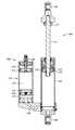
- FIG. 1is a section view of a damper with a remote reservoir.
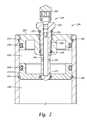
- FIG. 2is a section view of the remote reservoir of FIG. 1 showing a pre-charge assembly.
- FIG. 3is a section view of the remote reservoir of FIG. 2 , with the pre-charge assembly in a shifted position.
- FIG. 4is a section view of a remote reservoir showing a gas pressure indicator.
- FIG. 5is a section view of the remote reservoir of FIG. 3 with the pressure indictor incorporated therein.
- FIG. 1is a section view of a fluid damper 100 embodiment, typically for a motor vehicle.
- the main parts for the damperinclude a fluid chamber 105 and a rod 110 with a piston 115 disposed at the end thereof for extending into the fluid chamber 105 , thereby dividing the chamber into compression and rebound portions respectively on opposite sides of the piston 115 .
- the rod and pistonare shown in their fully extended position as they would appear at the beginning of a compression stroke (e.g. an uncompressed damper).
- the damperalso includes a remote reservoir 125 or compensation chamber, constructed and arranged to receive damping fluid via a communication, or fluid flow, path 130 .
- the remote reservoiris divided into a damping fluid 135 and a compressed gas portion 150 with the two portions separated by a floating piston 155 which, as described herein, is sealed with an O-ring 230 and moves against the volume of compressed gas in the gas portion 150 as fluid displaced from the fluid chamber 105 during a compression stroke of the damper moves into the fluid portion 135 of the remote reservoir 125 .
- the damper of FIG. 1is often installed as part of a vehicle suspension system and a mounting lug or “eyelet” 160 formed at an end of the fluid chamber is connected to the vehicle frame while another mounting lug 162 disposed at an end of the rod is attached to the vehicle wheel (not shown).
- a mounting lug or “eyelet” 160 formed at an end of the fluid chamberis connected to the vehicle frame while another mounting lug 162 disposed at an end of the rod is attached to the vehicle wheel (not shown).
- the piston 115 and rod 110move into and out of the fluid chamber 105 , metering fluid through communication paths 170 and shims in the piston.
- An annular bumper 175is disposed at an end of the piston rod 110 to prevent the assembly 100 from reaching a bottom-out condition.
- the damper of FIG. 1includes a pre-charge assembly 200 disposed at an end of the remote reservoir 125 (note that if the reservoir were in line with the damper so to would be such a pre-charge assembly).
- the pre-charge assemblyincludes a pre-charge gas portion 210 which is separated from the compressed gas portion 150 of the remote reservoir 125 by a partition 215 .
- the assembly 200also includes a fill/communication valve 220 constructed and arranged to permit initial charging of the pre-charge gas portion and to allow a user to permit fluid communication between the pre-charge portion 210 and the compressed gas portion 150 .
- FIG. 2is a section view of the pre-charge assembly 200 of FIG. 1 .
- the assembly 200is located at one end of the remote reservoir 125 of the damper 100 and the pre-charge portion 210 houses a volume of pressurized gas which is retained between an end cap 225 and partition 215 .
- Both the end cap and the partitionare sealed with O-rings 230 or other suitable seals and each is retained axially by structural rings 235 acting against shoulders 240 formed in the cap 225 and partition 215 to maintain structural integrity against the highly pressurized gas (e.g. 600-800 psi in one embodiment) that will be housed in the pre-charge portion 210 .
- the compressed gas portion 150is isolated from the pre-charge portion and gas pressure in portion 150 is limited to atmospheric pressure.
- the gas pressure in portion 150may be any suitable low pressure, preferably such that the net extension force acting on rod 110 due to the pressure may be overcome manually.
- a fill/communication valve 220Disposed in the pre-charge assembly is a fill/communication valve 220 intended to facilitate initial filling of the pre-charge portion 210 and to provide selective communication between the pre-charge portion 210 and the compressed gas portion 150 of the remote reservoir. Thereafter, the valve 220 provides a way to further fill or adjust the combined gas portion of the reservoir with pressurized gas.
- the valveis shown with a protective cap 245 threaded onto an end thereof.
- the fill/communication valve 220includes a central member 250 having external threads 255 which interact with internal threads 260 formed in the end cap 225 , whereby rotation of the central member 250 provides axial movement (corresponding to the thread pitch) of the communication valve 220 relative to the end cap 225 .
- the central member 250includes a seal 230 at each end of the threaded portions 255 , 260 .
- the cap gland interior seal 230engages a relatively smooth outer diameter of the central member 250 and seals initial pressure of the pre-charge portion 210 prior to movement of the central member 250 and corresponding gas commingling between the pre-charge portion 210 and the compressed gas portion 150 .
- An interior portion 265 of the central memberis hollow and a first communication path including apertures 270 is formed between the hollow portion of the central member 250 and the pre-charge portion 210 therearound.
- a first communication path including apertures 270is formed between the hollow portion of the central member 250 and the pre-charge portion 210 therearound.
- gas communicationexists only between the pre-charge portion and the central member (permitting the pre-charge portion to be initially charged without introducing gas pressure elsewhere).
- a second communication path apertures 275 extending from the interior portion 265 of the central memberis blocked in the position shown in FIG. 2 . The result is that in the position of FIG. 2 , there is no fluid communication from the pre-charge portion to any other operative portion of the damper 100 (i.e. the pre-charge is isolated by the central member 250 and the partition 215 .
- FIG. 3is another section view of the pre-charge assembly 200 of FIG. 2 showing the central member 250 in a shifted position, whereby fluid communication, illustrated by arrows 280 , is permitted between the pre-charge portion 210 and the compressed gas portion 150 of the reservoir 125 (via apertures 270 , bore 265 and apertures 275 ).
- the pre-charge assembly 200has been shifted by rotation of the central member 250 to provide axial movement of the fill/communication valve relative to the end cap 225 and relative to the partition 215 .
- compressed gasflows through the first communication path, through the interior portion 265 of the central member and exiting the second communication path 275 which has been placed into fluid communication with the compressed gas portion 150 .
- portions 210 and 125are combined to effectively form a single larger-volume gas portion at a pressure corresponding to a volume weighted combination of the pressures of the pre-charge and the compressed gas portions.
- partition 215comprises a rupture disk or frangible membrane.
- the membranecontains the pre-charge pressure under initial circumstances with the central member in its initial position.
- an end of the central memberis proximate the partition but does not necessarily penetrate it.
- the central memberincludes a relatively sharp end (end near apertures 275 ) that is capable of piercing the partition upon axial movement of the central member.
- the central memberis axially moved toward the membrane as described herein (or in other suitable fashion) and the sharp end of the central member pierces the partition thereby communicating the pre-charge portion gas with the compressed gas portion gas. That results in gas commingling as described herein.
- the rod and piston lengthcan be easily adjusted (for example manually) for installation.
- the central member of the fill/communication valveis threaded inwards, placing the second communication path apertures 275 in communication with the compressed gas portion of the damper, thereby permitting gas communication between the portions.
- the pre-charge assembly 200is utilized whereby an end user receives a damper with effectively no gas pressure acting upon the floating piston in the remote reservoir and hence no pressure acting on an end area of the piston rod 110 .
- the gas pressure(a higher pressure designed to be commingled at a lower equilibrium pressure) is all stored in the pre-charge portion 210 of the reservoir.
- the piston and rodare easily manipulated back and forth in the fluid chamber which facilitates mounting of the damper relative to mounting locations on the vehicle. Thereafter, the pre-charge assembly is shifted and the damper operates normally utilizing the combined gas portions 210 , 125 as a single gas volume.
- the fluid damperis intended to operate with 200 psi in the compressed gas portion of the remote reservoir 125 .
- 800 psi of pressureis placed into the pre-charge portion.
- the volume of pre-charge gas at 800 psicommingles with the volume of the compressed gas reservoir at atmospheric pressure resulting in 200 psi is available throughout the reservoir for normal operation in the damper.
- the fill/communication valve 220e.g. Schader type
- FIG. 4is a section view of a compressed gas portion 150 of a remote reservoir 125 having a gas pressure indicator assembly 300 .
- the compressed gas portion 150 shown in FIG. 4is part of a remote reservoir that operates with a floating piston (not shown) acting against a source of pressurized gas to provide increasing and decreasing volume for fluid displaced from a main fluid-filled dampening chamber.
- Shown in FIG. 4is an end of the reservoir housing 305 , an end cap 225 that is sealed with O-rings 315 and retained with structural rings 235 , a fill valve 310 with a cap 311 for communicating pressurized gas into the compressed gas portion 150 and the gas pressure indicator assembly 300 .
- the purpose of the assembly 300is to provide a visual indicator of the gas pressure in the gas portion.
- Gas pressure indicator assembly 300includes a shaft 315 with a piston surface 320 formed at a first end and exposed to the interior of the gas portion 150 , whereby pressurized gas in the gas portion acts upon piston surface 320 .
- the shaft 315is sealed in an aperture 330 formed in end cap 225 and sealed with O-ring 230 .
- the shaft and piston surfaceare biased towards the interior of the housing by a spring 325 .
- Opposite the piston surfaceis an indicator 340 constructed and arranged to be visible only when the shaft/piston surface are depressed against the spring 325 hence allowing 340 to extend beyond a surface of cap 225 .
- the assembly 300is designed whereby the spring 325 is overcome and the piston 320 is depressed when a predetermined pressure exists in the gas portion 150 of the reservoir.
- a predetermined pressureexists in the gas portion 150 of the reservoir.
- FIG. 4Such a position is shown in FIG. 4 with the shaft 315 urged in direction of arrow 316 and the indictor 340 in an extended position where it would be visible to a user.
- the indicatorInstead of checking the pressure with a gauge and depleting the gas portion of pressure in doing so (because a pressure gauge requires a volume of the gas being testing and consumes that volume for each test instance), the indicator provides visual assurance of the presence of a certain minimum amount of gas pressure.
- FIG. 5is a section view of the remote reservoir 125 of FIG. 3 with pressure indicator assembly 300 incorporated therein.
- the pre-charge assembly 200 with its pre-charge portion 210operates as described with reference to FIGS. 1-3 wherein the pre-charge portion retains the working gas pressure until an end user manipulates a fill/communication valve 220 to permit fluid communication between the pre-charge portion 210 and the compressed gas portion 150 (as described herein). Thereafter, the reservoir functions normally with a predetermined gas pressure available in both portions and both portions combined and functioning as one, larger volume compressed gas portion. Also included is the gas pressure indicator assembly 300 . In the embodiment shown in FIG. 5 , a portion of the shaft 315 including the piston surface 320 is extended to communicate with the compressed gas portion 150 of the reservoir.
- the pre-charge portion 210does not act axially on the shaft 315 because the shaft 315 runs entirely though the portion 210 and protrudes through each end with a diameter equal at each end (i.e. no net piston area on shaft 315 vis a vis volume of portion 210 ).
- the arrangement shown in FIG. 5operates as described herein regarding selective commingling of a pre-charge 210 and a gas compression chamber 150 .
- the indicator shaftis moved when compressed gas of portion 150 acting on piston area 320 overcomes spring 325 force. As such the indicator provides a visual indication that commingling has been successful following movement of the central member.
- the indicator 340not only provides a visual indicator of working gas pressure in the reservoir, but is useful in confirming that initial communication has taken place between the portions 210 , 150 after manipulation of the central member.
- the pressure indicator 340is shown in its extended position indicating the presence of at least a minimum amount of pressure in the compressed gas portion 150 .
Landscapes
- Engineering & Computer Science (AREA)
- General Engineering & Computer Science (AREA)
- Mechanical Engineering (AREA)
- Fluid-Damping Devices (AREA)
Abstract
Description
Claims (12)
Priority Applications (5)
| Application Number | Priority Date | Filing Date | Title |
|---|---|---|---|
| US12/900,687US8807300B2 (en) | 2009-10-26 | 2010-10-08 | Methods and apparatus for managing pressurized gas in fluid dampers |
| US14/331,133US9341226B2 (en) | 2009-10-26 | 2014-07-14 | Methods and apparatus for managing pressurized gas in fluid dampers |
| US15/136,148US10124642B2 (en) | 2009-10-26 | 2016-04-22 | Methods and apparatus for managing pressurized gas in fluid dampers |
| US16/159,403US10953716B2 (en) | 2009-10-26 | 2018-10-12 | Methods and apparatus for managing pressurized gas in fluid dampers |
| US17/205,479US20210206220A1 (en) | 2009-10-26 | 2021-03-18 | Methods and apparatus for managing pressurized gas in fluid dampers |
Applications Claiming Priority (3)
| Application Number | Priority Date | Filing Date | Title |
|---|---|---|---|
| US25494709P | 2009-10-26 | 2009-10-26 | |
| US26764609P | 2009-12-08 | 2009-12-08 | |
| US12/900,687US8807300B2 (en) | 2009-10-26 | 2010-10-08 | Methods and apparatus for managing pressurized gas in fluid dampers |
Related Child Applications (1)
| Application Number | Title | Priority Date | Filing Date |
|---|---|---|---|
| US14/331,133ContinuationUS9341226B2 (en) | 2009-10-26 | 2014-07-14 | Methods and apparatus for managing pressurized gas in fluid dampers |
Publications (2)
| Publication Number | Publication Date |
|---|---|
| US20110094833A1 US20110094833A1 (en) | 2011-04-28 |
| US8807300B2true US8807300B2 (en) | 2014-08-19 |
Family
ID=43897453
Family Applications (3)
| Application Number | Title | Priority Date | Filing Date |
|---|---|---|---|
| US12/900,687Active2031-10-11US8807300B2 (en) | 2009-10-26 | 2010-10-08 | Methods and apparatus for managing pressurized gas in fluid dampers |
| US14/331,133ActiveUS9341226B2 (en) | 2009-10-26 | 2014-07-14 | Methods and apparatus for managing pressurized gas in fluid dampers |
| US15/136,148Active2030-11-06US10124642B2 (en) | 2009-10-26 | 2016-04-22 | Methods and apparatus for managing pressurized gas in fluid dampers |
Family Applications After (2)
| Application Number | Title | Priority Date | Filing Date |
|---|---|---|---|
| US14/331,133ActiveUS9341226B2 (en) | 2009-10-26 | 2014-07-14 | Methods and apparatus for managing pressurized gas in fluid dampers |
| US15/136,148Active2030-11-06US10124642B2 (en) | 2009-10-26 | 2016-04-22 | Methods and apparatus for managing pressurized gas in fluid dampers |
Country Status (1)
| Country | Link |
|---|---|
| US (3) | US8807300B2 (en) |
Cited By (8)
| Publication number | Priority date | Publication date | Assignee | Title |
|---|---|---|---|---|
| US20150283928A1 (en)* | 2013-03-14 | 2015-10-08 | Alan Bauman | Seat suspension |
| US9341226B2 (en) | 2009-10-26 | 2016-05-17 | Fox Factory, Inc. | Methods and apparatus for managing pressurized gas in fluid dampers |
| WO2017142926A1 (en)* | 2016-02-16 | 2017-08-24 | Baker Hughes Incorporated | Local position indicator for subsea isolation valve having no external position indication |
| US10953716B2 (en) | 2009-10-26 | 2021-03-23 | Fox Factory, Inc. | Methods and apparatus for managing pressurized gas in fluid dampers |
| US20210131522A1 (en)* | 2019-11-04 | 2021-05-06 | Beijingwest Industries Co., Ltd. | Bracket for attachment with a hydraulic damper assembly and a method of joining a bracket and a hydraulic damper assembly |
| US11434968B2 (en)* | 2019-02-25 | 2022-09-06 | Mark Brendan Newhan | Vehicle shock absorber |
| US11639212B2 (en) | 2019-04-10 | 2023-05-02 | Hayes Bicycle Group Inc. | Suspension assembly |
| US12442429B2 (en) | 2021-05-12 | 2025-10-14 | Vorsprung Technologies, Ltd. | High dynamic range suspension apparatus with selective fluid pressure communication |
Families Citing this family (14)
| Publication number | Priority date | Publication date | Assignee | Title |
|---|---|---|---|---|
| US8740237B2 (en)* | 2011-09-23 | 2014-06-03 | Specialized Bicycle Components, Inc. | Bicycle with suspension |
| US9765641B2 (en)* | 2012-08-23 | 2017-09-19 | Bell Helicopter Textron Inc. | System and method for vibration isolation |
| CN105443637A (en)* | 2015-12-31 | 2016-03-30 | 河海大学常州校区 | Energy storing type buffer |
| CN106763414B (en)* | 2016-12-16 | 2019-06-04 | 北京理工大学 | A gas-liquid two-phase oil-gas spring |
| US10549803B2 (en)* | 2017-06-30 | 2020-02-04 | Sram, Llc | Seat post assembly |
| US10668968B2 (en)* | 2017-06-30 | 2020-06-02 | Sram, Llc | Seat post assembly |
| USD872837S1 (en) | 2017-08-28 | 2020-01-14 | Qa1 Precision Products, Inc. | Bleed needle |
| USD869259S1 (en) | 2017-08-28 | 2019-12-10 | Qa1 Precision Products, Inc. | Valve component |
| US11085502B2 (en) | 2017-08-28 | 2021-08-10 | Qa1 Precision Products, Inc. | Bleed needle for a hydraulic system |
| US11105390B2 (en) | 2017-08-28 | 2021-08-31 | Qa1 Precision Products, Inc. | Shock absorber with dry valving |
| USD866408S1 (en) | 2017-08-28 | 2019-11-12 | Qa1 Precision Products, Inc. | Shock absorber |
| EP4191089A1 (en)* | 2021-12-03 | 2023-06-07 | Chih-Hsien Liao | Cylinder with switchable system and shock absorber having the same |
| CN115013465B (en)* | 2022-07-01 | 2024-04-12 | 北京汽车集团越野车有限公司 | Adjustable energy accumulator assembly and vehicle with same |
| US12409690B1 (en)* | 2024-06-09 | 2025-09-09 | L&H Industrial, Inc. | Vehicle suspension assembly |
Citations (7)
| Publication number | Priority date | Publication date | Assignee | Title |
|---|---|---|---|---|
| US5400880A (en)* | 1994-01-27 | 1995-03-28 | Competition Tire East | Bi-linear platform reactive damper |
| US20030067103A1 (en)* | 2001-10-04 | 2003-04-10 | Easter Mark R. | Dual rate air spring |
| US20030234144A1 (en)* | 2002-06-25 | 2003-12-25 | Fox Robert C. | On-the-fly adjustable air spring |
| US20060102440A1 (en)* | 2004-11-18 | 2006-05-18 | Ohlins Racing Ab | Shock absorber for vehicles |
| US7124865B2 (en)* | 2004-02-13 | 2006-10-24 | Progressive Suspension, Inc. | Pressure regulating dampers |
| US20080116622A1 (en)* | 2006-11-16 | 2008-05-22 | Fox Factory, Inc. | Gas spring curve control in an adjustable-volume gas-pressurized device |
| US7870936B2 (en)* | 2006-08-18 | 2011-01-18 | Sram, Llc | Bicycle suspension system |
Family Cites Families (9)
| Publication number | Priority date | Publication date | Assignee | Title |
|---|---|---|---|---|
| JPS5582833A (en)* | 1978-12-19 | 1980-06-21 | Yamaha Motor Co Ltd | Oil shock absorber |
| JPS5983846A (en)* | 1982-11-01 | 1984-05-15 | Yamaha Motor Co Ltd | Hydraulic buffer |
| NL8204790A (en)* | 1982-12-10 | 1984-07-02 | Fokker Bv | DOUBLE ACTING OLEO-PNEUMATIC SHOCK ABSORBER. |
| US4844428A (en)* | 1987-03-31 | 1989-07-04 | Aisin Seiki Kabushiki Kaisha | Air spring assembly |
| JPH04372410A (en)* | 1991-06-20 | 1992-12-25 | Tokico Ltd | Suspension device |
| SE515321C2 (en)* | 1998-12-02 | 2001-07-16 | Oehlins Racing Ab | Shock absorber with cylinder comprising a piston rod with at least two pistons |
| FR2825767B1 (en)* | 2001-06-12 | 2003-08-15 | Realisation Dev Concept | VERSATILE HYDRAULIC SHOCK ABSORBER FOR VEHICLE |
| CA2409811A1 (en)* | 2001-10-29 | 2003-04-29 | Bombardier Inc. | Shock absorber with a gas chamber on the rebound side of a piston |
| US8807300B2 (en)* | 2009-10-26 | 2014-08-19 | Fox Factory, Inc. | Methods and apparatus for managing pressurized gas in fluid dampers |
- 2010
- 2010-10-08USUS12/900,687patent/US8807300B2/enactiveActive
- 2014
- 2014-07-14USUS14/331,133patent/US9341226B2/enactiveActive
- 2016
- 2016-04-22USUS15/136,148patent/US10124642B2/enactiveActive
Patent Citations (7)
| Publication number | Priority date | Publication date | Assignee | Title |
|---|---|---|---|---|
| US5400880A (en)* | 1994-01-27 | 1995-03-28 | Competition Tire East | Bi-linear platform reactive damper |
| US20030067103A1 (en)* | 2001-10-04 | 2003-04-10 | Easter Mark R. | Dual rate air spring |
| US20030234144A1 (en)* | 2002-06-25 | 2003-12-25 | Fox Robert C. | On-the-fly adjustable air spring |
| US7124865B2 (en)* | 2004-02-13 | 2006-10-24 | Progressive Suspension, Inc. | Pressure regulating dampers |
| US20060102440A1 (en)* | 2004-11-18 | 2006-05-18 | Ohlins Racing Ab | Shock absorber for vehicles |
| US7870936B2 (en)* | 2006-08-18 | 2011-01-18 | Sram, Llc | Bicycle suspension system |
| US20080116622A1 (en)* | 2006-11-16 | 2008-05-22 | Fox Factory, Inc. | Gas spring curve control in an adjustable-volume gas-pressurized device |
Cited By (15)
| Publication number | Priority date | Publication date | Assignee | Title |
|---|---|---|---|---|
| US10124642B2 (en)* | 2009-10-26 | 2018-11-13 | Fox Factory, Inc. | Methods and apparatus for managing pressurized gas in fluid dampers |
| US9341226B2 (en) | 2009-10-26 | 2016-05-17 | Fox Factory, Inc. | Methods and apparatus for managing pressurized gas in fluid dampers |
| US20160236530A1 (en)* | 2009-10-26 | 2016-08-18 | Fox Factory, Inc. | Methods and apparatus for managing pressurized gas in fluid dampers |
| US10953716B2 (en) | 2009-10-26 | 2021-03-23 | Fox Factory, Inc. | Methods and apparatus for managing pressurized gas in fluid dampers |
| US9707874B2 (en)* | 2013-03-14 | 2017-07-18 | Alan Bauman | Seat suspension |
| US10131254B2 (en)* | 2013-03-14 | 2018-11-20 | Alan Bauman | Seat suspension |
| US20150283928A1 (en)* | 2013-03-14 | 2015-10-08 | Alan Bauman | Seat suspension |
| WO2017142926A1 (en)* | 2016-02-16 | 2017-08-24 | Baker Hughes Incorporated | Local position indicator for subsea isolation valve having no external position indication |
| GB2563176A (en)* | 2016-02-16 | 2018-12-05 | Baker Hughes A Ge Co Llc | Local position indicator for subsea isolation valve having no external position indication |
| GB2563176B (en)* | 2016-02-16 | 2020-06-24 | Baker Hughes A Ge Co Llc | Local position indicator for subsea isolation valve having no external position indication |
| US11434968B2 (en)* | 2019-02-25 | 2022-09-06 | Mark Brendan Newhan | Vehicle shock absorber |
| US11639212B2 (en) | 2019-04-10 | 2023-05-02 | Hayes Bicycle Group Inc. | Suspension assembly |
| US20210131522A1 (en)* | 2019-11-04 | 2021-05-06 | Beijingwest Industries Co., Ltd. | Bracket for attachment with a hydraulic damper assembly and a method of joining a bracket and a hydraulic damper assembly |
| US11512758B2 (en)* | 2019-11-04 | 2022-11-29 | Beijingwest Industries Co., Ltd. | Bracket for attachment with a hydraulic damper assembly and a method of joining a bracket and a hydraulic damper assembly |
| US12442429B2 (en) | 2021-05-12 | 2025-10-14 | Vorsprung Technologies, Ltd. | High dynamic range suspension apparatus with selective fluid pressure communication |
Also Published As
| Publication number | Publication date |
|---|---|
| US20110094833A1 (en) | 2011-04-28 |
| US9341226B2 (en) | 2016-05-17 |
| US20160236530A1 (en) | 2016-08-18 |
| US20140326554A1 (en) | 2014-11-06 |
| US10124642B2 (en) | 2018-11-13 |
Similar Documents
| Publication | Publication Date | Title |
|---|---|---|
| US8807300B2 (en) | Methods and apparatus for managing pressurized gas in fluid dampers | |
| US20210206220A1 (en) | Methods and apparatus for managing pressurized gas in fluid dampers | |
| US12129909B2 (en) | Method and apparatus for an adjustable damper | |
| US6311962B1 (en) | Shock absorber with external air cylinder spring | |
| US10400847B2 (en) | Compression isolator for a suspension damper | |
| KR101633651B1 (en) | A triple tube shock absorber having a shortened intermediate tube | |
| US8746661B2 (en) | Hydro-pneumatic piston accumulator | |
| CN102574440B (en) | Damper with digital valve | |
| CN102165214B (en) | High velocity compression damping valve | |
| JP2950594B2 (en) | Shock absorber including valve for hydraulic fluid | |
| US9863494B2 (en) | Suspension damper | |
| US20030051957A1 (en) | Shock absorber with a floating piston | |
| EP2892740B1 (en) | An air spring with a linearized spring rate | |
| KR20130082082A (en) | Two stage valve and hydraulic damped valve | |
| US9285011B2 (en) | High velocity compression damping valve | |
| US7252031B2 (en) | Cylinder apparatus | |
| EP3242053B1 (en) | Suspension apparatus | |
| US20020139624A1 (en) | Twin-tube magnetorheological damper | |
| US6357734B1 (en) | Suspension damper with vehicle spring preload | |
| US20040256186A1 (en) | Spring-less monotube shock absorber |
Legal Events
| Date | Code | Title | Description |
|---|---|---|---|
| AS | Assignment | Owner name:FOX FACTORY, INC., CALIFORNIA Free format text:ASSIGNMENT OF ASSIGNORS INTEREST;ASSIGNOR:MARKING, JOHN;REEL/FRAME:025315/0918 Effective date:20101021 | |
| AS | Assignment | Owner name:COMPASS GROUP DIVERSIFIED HOLDINGS LLC, CONNECTICU Free format text:FIRST AMENDMENT TO INTELLECTUAL PROPERTY SECURITY AGREEMENT;ASSIGNOR:FOX FACTORY, INC.;REEL/FRAME:027124/0088 Effective date:20111025 | |
| AS | Assignment | Owner name:FOX FACTORY, INC., CALIFORNIA Free format text:RELEASE BY SECURED PARTY;ASSIGNOR:COMPASS DIVERSIFIED HOLDINGS LLC;REEL/FRAME:031007/0958 Effective date:20130813 | |
| AS | Assignment | Owner name:FOX FACTORY, INC., CALIFORNIA Free format text:CORRECTIVE ASSIGNMENT TO CORRECT THE TO CORRECT THE PATENT SCHEDULE TO REMOVE APPLICATION #13900687 PREVIOUSLY RECORDED ON REEL 031007 FRAME 0958. ASSIGNOR(S) HEREBY CONFIRMS THE RELEASE OF PATENT SECURITY INTEREST;ASSIGNOR:COMPASS GROUP DIVERSIFIED HOLDINGS LLC;REEL/FRAME:031160/0511 Effective date:20130813 | |
| AS | Assignment | Owner name:FOX FACTORY, INC., CALIFORNIA Free format text:CORRECTIVE ASSIGNMENT TO CORRECT THE ASSIGNOR'S NAME PREVIOUSLY RECORDED ON REEL 031007 FRAME 0958. ASSIGNOR(S) HEREBY CONFIRMS THE RELEASE OF TRADEMARK SECURITY INTEREST;ASSIGNOR:COMPASS GROUP DIVERSIFIED HOLDINGS LLC;REEL/FRAME:031059/0649 Effective date:20130813 | |
| STCF | Information on status: patent grant | Free format text:PATENTED CASE | |
| MAFP | Maintenance fee payment | Free format text:PAYMENT OF MAINTENANCE FEE, 4TH YEAR, LARGE ENTITY (ORIGINAL EVENT CODE: M1551) Year of fee payment:4 | |
| AS | Assignment | Owner name:BANK OF AMERICA, N.A., AS ADMINISTRATIVE AGENT, CA Free format text:PATENT SECURITY AGREEMENT;ASSIGNOR:FOX FACTORY, INC.;REEL/FRAME:049388/0585 Effective date:20190603 Owner name:BANK OF AMERICA, N.A., AS ADMINISTRATIVE AGENT, CALIFORNIA Free format text:PATENT SECURITY AGREEMENT;ASSIGNOR:FOX FACTORY, INC.;REEL/FRAME:049388/0585 Effective date:20190603 | |
| MAFP | Maintenance fee payment | Free format text:PAYMENT OF MAINTENANCE FEE, 8TH YEAR, LARGE ENTITY (ORIGINAL EVENT CODE: M1552); ENTITY STATUS OF PATENT OWNER: LARGE ENTITY Year of fee payment:8 | |
| AS | Assignment | Owner name:WELLS FARGO BANK, NATIONAL ASSOCIATION, NORTH CAROLINA Free format text:SECURITY INTEREST;ASSIGNOR:FOX FACTORY, INC.;REEL/FRAME:059616/0435 Effective date:20220405 | |
| AS | Assignment | Owner name:FOX FACTORY, INC., GEORGIA Free format text:RELEASE BY SECURED PARTY;ASSIGNOR:BANK OF AMERICA, N.A.;REEL/FRAME:059704/0224 Effective date:20220405 |