US8806886B2 - Temperature controlled devices - Google Patents
Temperature controlled devicesDownload PDFInfo
- Publication number
- US8806886B2 US8806886B2US11/960,956US96095607AUS8806886B2US 8806886 B2US8806886 B2US 8806886B2US 96095607 AUS96095607 AUS 96095607AUS 8806886 B2US8806886 B2US 8806886B2
- Authority
- US
- United States
- Prior art keywords
- quick disconnect
- heat exchanger
- control circuit
- temperature control
- port
- Prior art date
- Legal status (The legal status is an assumption and is not a legal conclusion. Google has not performed a legal analysis and makes no representation as to the accuracy of the status listed.)
- Active, expires
Links
Images


Classifications
- F—MECHANICAL ENGINEERING; LIGHTING; HEATING; WEAPONS; BLASTING
- F25—REFRIGERATION OR COOLING; COMBINED HEATING AND REFRIGERATION SYSTEMS; HEAT PUMP SYSTEMS; MANUFACTURE OR STORAGE OF ICE; LIQUEFACTION SOLIDIFICATION OF GASES
- F25D—REFRIGERATORS; COLD ROOMS; ICE-BOXES; COOLING OR FREEZING APPARATUS NOT OTHERWISE PROVIDED FOR
- F25D11/00—Self-contained movable devices, e.g. domestic refrigerators
- F25D11/02—Self-contained movable devices, e.g. domestic refrigerators with cooling compartments at different temperatures
- F25D11/025—Self-contained movable devices, e.g. domestic refrigerators with cooling compartments at different temperatures using primary and secondary refrigeration systems
Definitions
- This inventionrelates generally to temperature-controlled devices, and more particularly, to temperature controlled devices utilizing a secondary cooling loop from a primary cooling source.
- refrigeration systemsfor commercial or institutional food sales or food service facilities such as supermarkets, grocery stores, cafeterias, etc.
- These refrigeration systemsoperate with refrigeration or cooling devices such as temperature controlled cases (individually or in groups) that use air-cooled or water-cooled condensers supplied by a rack of compressors.
- refrigeration or cooling devicessuch as temperature controlled cases (individually or in groups) that use air-cooled or water-cooled condensers supplied by a rack of compressors.
- modern supermarket applicationstypically have many individual or grouped refrigeration devices located throughout the shopping or display area of the supermarket.
- Each refrigeration deviceis provided with a cooling interface such as an evaporator or cooling coil that receives refrigerant from the refrigeration system in a closed loop configuration where the refrigerant is expanded to a low pressure and temperature state for circulation through the cooling interface to cool the space and objects within the refrigeration device.
- one or more condensersare typically located either outside, on the roof, or in a machine room or back room adjacent to the shopping or display area where the refrigeration devices are located and are used to cool the refrigerant that is distributed to all or a group of these refrigeration devices.
- thermoelectric coolinghas low efficiency, low capacity, and a high thermal inertia.
- the compressorutilizes electricity through a pump to compress a refrigerant.
- Each compressoroccupies space and can be a source of noise.
- the refrigerantis cooled in a coil exposed to the ambient air of the residence or other location of the circuit.
- the refrigerantis then depressurized reducing the temperature of the refrigerant.
- the reduced temperature refrigerantis used in a heat exchanger within the device to be cooled to reduce the temperature.
- Each of these stageshas inefficiencies in the form of heat or electrical consumption.
- a distributed refrigeration systemhaving a stand-alone refrigeration device with a self-contained refrigeration system that is suitably efficient for residential viability. It would be further advantageous to provide a distributed refrigeration system having a sufficiently low noise level. It would also be advantageous to provide a distributed refrigeration system that reduces the amount of refrigerant or evaporative/condenser systems thus reducing potential environmental hazards. It would also be advantageous to provide a distributed refrigeration system permitting the connection of devices thereto and having applications that are not possible where an individual refrigeration circuit would be required. It would be further advantageous to provide a distributed refrigeration system having a central electrical unit in which all electrical functions of the distributed refrigeration unit are pre-wired at the factory and require only a single electrical power hook up when installed in a home.
- a refrigeratorin one aspect, is provided.
- a temperature controlled compartment in a refrigeratorthat includes a heat exchanger configured to have the cooling medium flow therethrough to be cooled in thermal communication with a freezer compartment of the refrigerator.
- a second heat exchangerdisposed downstream of the first heat exchanger and configured to have the cooling medium flow therethrough to cool the temperature-controlled compartment.
- a pumpconfigured to flow the cooling medium through the first and second heat exchangers.
- a first heat exchangeris disposed downstream of the storage tank and is configured to have the cooling medium flow therethrough to be cooled.
- a second heat exchangeris disposed downstream of the first heat exchanger and is configured to have the cooling medium flow therethrough to cool the air and any contents within the temperature controlled compartment.
- a methodfor a chilled compartment in a refrigerator. First, flowing a refrigerant through a cooling system to cool a first interior compartment of the refrigerator. Then, flowing a cooling medium different from the refrigerant through a first heat exchanger disposed within the first interior compartment to decrease the temperature of the cooling medium. Finally, flowing the cooling medium through a second heat exchanger in thermal communication with the chilled compartment to reduce the temperature of the chilled compartment.
- a refrigeratorhaving a compartment cooling section configured to cool an interior compartment of the refrigerator.
- the compartment cooling sectionhas a first heat exchanger configured to have a refrigerant flow through it to absorb heat.
- An ice producing apparatusis configured to produce ice and to deliver the ice through an opening in a door of the refrigerator.
- the ice producing apparatushas a storage tank configured to store a cooling medium. It also has a second heat exchanger disposed downstream of the storage tank that is configured to have the cooling medium flow through it to be cooled.
- An ice mold with at least one cavity that is configured to retain water thereinis in thermal communication with a third heat exchanger that is disposed downstream of the second heat exchanger and configured to have the cooling medium flow through it to freeze the water in the ice mold to produce ice.
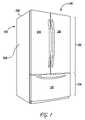
- FIG. 1is a perspective view of a known refrigerator.
- FIG. 2is a perspective view of the refrigerator of FIG. 1 with the refrigerator doors open.
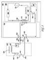
- FIG. 3is a schematic view of an embodiment of the invention.
- FIGS. 1 and 2illustrate a side-by-side refrigerator 100 including a fresh food compartment 102 and freezer compartment 104 .
- Freezer compartment 104 and fresh food compartment 102are arranged in a bottom mount configuration where the freezer compartment 104 is below the fresh food compartment 102 .
- the fresh food compartmentis shown with French opening doors 134 and 135 . However, a single door may be used.
- Door or drawer 132closes freezer compartment 104 .
- the fresh food compartment 102 and freezer compartment 104are contained within an outer case 106 .
- Outer case 106normally is formed by folding a sheet of a suitable material, such as pre-painted steel, into an inverted U-shape to form top and sidewalls 230 , 232 of case 106 .
- Mullion 114is preferably formed of an extruded ABS material. As shown in FIG. 2 , Mullion 114 separates the fresh food compartment 102 and the freezer compartment 104 .
- Door 132 and doors 134 , 135close access openings to freezer and fresh food compartments 104 , 102 , respectively.
- Each door 134 and 135is mounted by a top hinge 136 and a bottom hinge 137 to rotate about its outer vertically oriented edge between an open position, as shown in FIG. 2 , and a closed position shown in FIG. 1 closing the associated storage compartment.
- refrigerator 100also includes a machinery compartment (not shown) that at least partially contains components for executing a known vapor compression cycle for cooling air in the compartments.
- the componentsinclude a compressor (shown schematically in FIG. 3 as 151 ), a condenser (shown schematically in FIG. 3 as 152 ), an expansion device (shown schematically in FIG. 3 as 155 ), and an evaporator (shown schematically in FIG. 3 as 156 ) connected in series and charged with a refrigerant.
- the evaporatoris a type of heat exchanger that transfers heat from air passing over the evaporator to a refrigerant flowing through the evaporator, thereby causing the refrigerant to vaporize.
- the cooled airis used to refrigerate one or more fresh food or freezer compartments via fans (shown schematically in FIG. 3 as 157 ).
- fansshown schematically in FIG. 3 as 157 .
- the vapor compression cycle components in a refrigeration circuit, associated fans, and associated compartmentsare referred to herein as a sealed system.
- the construction of the sealed systemis well known and therefore not described in detail herein, and the sealed system is operable to force cold air through the refrigerator 100 .
- the secondary loop temperature control circuit or distributed temperature system of the present inventionmay be used for a variety of distributed temperature control applications where localized temperature control is desired. These applications may including more than one temperature controlled compartments or regions that may be zoned with valves or other mechanisms.
- FIG. 3is a schematic view of an embodiment of the invention.
- the refrigerator 100contains a temperature control circuit, the temperature control circuit is a vapor-compression circuit 150 , which is known in the art.
- the vapor compression circuit 150has a compressor 151 for compressing a working fluid. When compressed the working fluid becomes heated, heat is removed in coil 152 . The working fluid is decompressed or vaporized at 155 thereby further cooling the working fluid. The working fluid passes through medium heat exchanger 310 before entering evaporator 156 .
- Evaporator 156may have a fan 157 to circulate air from freezer compartment 104 in a plenum (not shown) past evaporator 156 and back to freezer compartment 104 thereby cooling freezer compartment 104 .
- heat exchanger 310thermally connects the vapor-compression circuit 150 with the distributed temperature system of the present invention.
- heat exchanger 310may not be directly connected to the vapor compression circuit 150 and may utilize heat transfer to the freezer compartment 104 as a means of cooling the working medium in the distributed temperature system. It can be appreciated that by locating the heat exchanger 310 between compressor 151 and the coil 152 , heat may be transferred to the working medium of the distributed temperature system of the invention.
- the distributed temperature systemutilizes a working medium, hereinafter “medium”.
- the mediumis preferably a food safe medium, such as propylene glycol.
- the working mediumflows in tubes or conduits connecting the components of the system.
- Heat exchanger 310has a coil 311 as a part of the vapor compression circuit 150 and a coil 312 as a part of the distributed temperature system.
- the coils 311 and 312are in thermal communication generally by a working fluid thereby transferring heat from one system to the other. It can be appreciated that coil 312 may be removed and the medium may flow around coil 311 thereby transferring heat directly to the medium.
- Tank 301 of the distributed temperature systemallows a quantity of the medium to be maintained in the system.
- the tank 301may contain a means for adding additional medium to the distributed temperature system.
- Output ports 321 and 322are provided in an exterior surface of the refrigerator 100 . It can be appreciated that any number of output ports 321 , 322 can be provided in the exterior of refrigerator 100 . Output port 323 is provided on the interior of the refrigerator 100 . It can be appreciated that while only one output port 323 is shown in the freezer compartment 104 of refrigerator 100 , multiple output ports may be provided in either the freezer compartment 104 or fresh food compartment 102 of refrigerator 100 .
- input ports 331 and 332are also provided in an exterior surface of the refrigerator 100 . It can be appreciated that any number of input ports 331 , 332 can be provided in the exterior of refrigerator 100 .
- Input port 333is provided on the interior of the refrigerator 100 . It can be appreciated that while only one input port 323 is shown in the freezer compartment 104 of refrigerator 100 , multiple input ports may be provided in either the freezer compartment 104 or fresh food compartment 102 of refrigerator 100 .
- multiple devices 400may be connected to the distributed temperature system in parallel.
- each device 400receives medium directly from heat exchanger 310 . In this configuration each device 400 receives medium of similar temperature.
- Output ports 321 , 322 , 323 and input ports 331 , 332 , 333are configured such that when no device is connected, flow through the disconnected port is prevented.
- One such configuration used to achieve this functionalitycomprises a hydraulic quick disconnect with an internal valve, however, any interconnect may be used which prevents leakage of the medium when the port is not used.
- Device 400is connected to the distributed temperature system by similar quick disconnects at device input port 421 and device output port 431 .
- Mediumflows into the device 400 to a tank 401 .
- Tank 401may contain a volume of storage or may be a means of removing air from the device 400 .
- Device heat exchanger 412thermally connects the medium to the device 400 .
- heatis transferred by conduction between the heat exchanger 412 and device 400 .
- a fan 405may be used to accelerate the transfer of heat between the device heat exchanger 412 and the device 400 in combination with convection heat exchange within device 400 .
- a device pump 402may be incorporated in the device 400 to facilitate flow of the medium.
- Device 400may also include an auxiliary output port 423 and auxiliary input port 433 .
- Auxiliary ports 423 and 433permit the connection of additional devices serially with device 400 .
- the distributed temperature systemmay comprise a pair of circuits offering both a cooling circuit and a heating circuit.
- Output ports 321 , 322 and 323 or input ports 331 , 332 and 333may incorporate an electrical interconnect.
- the electrical interconnectbeing designed to facilitate communications between the device 400 and components of the distributed temperature system. Such communications may include a pump signal to activate pump 302 , a temperature signal indicating a temperature of the device 400 .
- Device 400may be any household device that must be kept at a temperature other then the ambient temperature within the house.
- Devicesinclude a surface such a chilled surface to hold vegetable trays or for working with food or a heated surface for keeping foods or other items warm.
- Other devicesinclude a stand-alone ice-maker or ice holder, a fast chill compartment, a chiller or heater for drinking water supply, a soda or beer (keg-orator) chiller, a dehumidifier heating or cooling side.
- Further applications for a distributed temperature systeminclude a compartment for thawing food, a wine chiller, a glass chiller for frosted mugs/glasses or to quick chill a portable cooling device such as a cold pack or a cooler.
Landscapes
- Engineering & Computer Science (AREA)
- Chemical & Material Sciences (AREA)
- Combustion & Propulsion (AREA)
- Physics & Mathematics (AREA)
- Mechanical Engineering (AREA)
- Thermal Sciences (AREA)
- General Engineering & Computer Science (AREA)
- Devices That Are Associated With Refrigeration Equipment (AREA)
Abstract
Description
Claims (20)
Priority Applications (2)
| Application Number | Priority Date | Filing Date | Title |
|---|---|---|---|
| US11/960,956US8806886B2 (en) | 2007-12-20 | 2007-12-20 | Temperature controlled devices |
| CA2638296ACA2638296C (en) | 2007-12-20 | 2008-07-25 | Temperature controlled devices |
Applications Claiming Priority (1)
| Application Number | Priority Date | Filing Date | Title |
|---|---|---|---|
| US11/960,956US8806886B2 (en) | 2007-12-20 | 2007-12-20 | Temperature controlled devices |
Publications (2)
| Publication Number | Publication Date |
|---|---|
| US20090158768A1 US20090158768A1 (en) | 2009-06-25 |
| US8806886B2true US8806886B2 (en) | 2014-08-19 |
Family
ID=40787006
Family Applications (1)
| Application Number | Title | Priority Date | Filing Date |
|---|---|---|---|
| US11/960,956Active2028-11-05US8806886B2 (en) | 2007-12-20 | 2007-12-20 | Temperature controlled devices |
Country Status (2)
| Country | Link |
|---|---|
| US (1) | US8806886B2 (en) |
| CA (1) | CA2638296C (en) |
Families Citing this family (27)
| Publication number | Priority date | Publication date | Assignee | Title |
|---|---|---|---|---|
| US8794026B2 (en)* | 2008-04-18 | 2014-08-05 | Whirlpool Corporation | Secondary cooling apparatus and method for a refrigerator |
| US20090288445A1 (en)* | 2008-05-21 | 2009-11-26 | Sanjay Anikhindi | Modular household refrigeration system and method |
| US20120111038A1 (en) | 2010-11-04 | 2012-05-10 | International Business Machines Corporation | Vapor-compression refrigeration apparatus with backup air-cooled heat sink and auxiliary refrigerant heater |
| US8955346B2 (en) | 2010-11-04 | 2015-02-17 | International Business Machines Corporation | Coolant-buffered, vapor-compression refrigeration apparatus and method with controlled coolant heat load |
| US8783052B2 (en) | 2010-11-04 | 2014-07-22 | International Business Machines Corporation | Coolant-buffered, vapor-compression refrigeration with thermal storage and compressor cycling |
| US8899052B2 (en) | 2010-11-04 | 2014-12-02 | International Business Machines Corporation | Thermoelectric-enhanced, refrigeration cooling of an electronic component |
| US8833096B2 (en) | 2010-11-04 | 2014-09-16 | International Business Machines Corporation | Heat exchange assembly with integrated heater |
| US8813515B2 (en) | 2010-11-04 | 2014-08-26 | International Business Machines Corporation | Thermoelectric-enhanced, vapor-compression refrigeration apparatus facilitating cooling of an electronic component |
| US9625202B2 (en)* | 2011-03-02 | 2017-04-18 | Whirlpoo Corporation | Direct contact icemaker with finned air cooling capacity |
| US9207002B2 (en) | 2011-10-12 | 2015-12-08 | International Business Machines Corporation | Contaminant separator for a vapor-compression refrigeration apparatus |
| US20150000318A1 (en)* | 2011-12-20 | 2015-01-01 | Dometic S.A.R.L. | Cooling device and method for controlling a cooling device |
| DE102012201089A1 (en)* | 2012-01-25 | 2013-07-25 | BSH Bosch und Siemens Hausgeräte GmbH | REFRIGERATOR WITH A REFRIGERATOR |
| US9151524B2 (en) | 2012-12-03 | 2015-10-06 | Whirlpool Corporation | Refrigerator with icemaker chilled by thermoelectric device cooled by fresh food compartment air |
| US9383128B2 (en) | 2012-12-03 | 2016-07-05 | Whirlpool Corporation | Refrigerator with ice mold chilled by air exchange cooled by fluid from freezer |
| US9182157B2 (en) | 2012-12-03 | 2015-11-10 | Whirlpool Corporation | On-door ice maker cooling |
| US9115918B2 (en) | 2012-12-03 | 2015-08-25 | Whirlpool Corporation | Refrigerator with icemaker chilled by thermoelectric device cooled by fresh food compartment air |
| US9593870B2 (en) | 2012-12-03 | 2017-03-14 | Whirlpool Corporation | Refrigerator with thermoelectric device for ice making |
| US9766005B2 (en) | 2012-12-03 | 2017-09-19 | Whirlpool Corporation | Refrigerator with ice mold chilled by fluid exchange from thermoelectric device with cooling from fresh food compartment or freezer compartment |
| US9562707B2 (en) | 2013-03-14 | 2017-02-07 | Whirlpool Corporation | Refrigerator cooling system having a secondary cooling loop |
| KR102261114B1 (en)* | 2015-01-23 | 2021-06-07 | 엘지전자 주식회사 | Refrigerator |
| KR20170067559A (en)* | 2015-12-08 | 2017-06-16 | 엘지전자 주식회사 | A refrigerator and a method for controlling the same |
| US10633785B2 (en) | 2016-08-10 | 2020-04-28 | Whirlpool Corporation | Maintenance free dryer having multiple self-cleaning lint filters |
| US10738411B2 (en) | 2016-10-14 | 2020-08-11 | Whirlpool Corporation | Filterless air-handling system for a heat pump laundry appliance |
| US10519591B2 (en) | 2016-10-14 | 2019-12-31 | Whirlpool Corporation | Combination washing/drying laundry appliance having a heat pump system with reversible condensing and evaporating heat exchangers |
| US10502478B2 (en) | 2016-12-20 | 2019-12-10 | Whirlpool Corporation | Heat rejection system for a condenser of a refrigerant loop within an appliance |
| US10514194B2 (en) | 2017-06-01 | 2019-12-24 | Whirlpool Corporation | Multi-evaporator appliance having a multi-directional valve for delivering refrigerant to the evaporators |
| US10718082B2 (en) | 2017-08-11 | 2020-07-21 | Whirlpool Corporation | Acoustic heat exchanger treatment for a laundry appliance having a heat pump system |
Citations (52)
| Publication number | Priority date | Publication date | Assignee | Title |
|---|---|---|---|---|
| US1962580A (en) | 1929-01-18 | 1934-06-12 | Max B Miller & Co Inc | Chilling |
| US1992018A (en) | 1933-02-24 | 1935-02-19 | Gen Electric | Refrigerator evaporator |
| US2120185A (en) | 1934-10-03 | 1938-06-07 | Nash Kelvinator Corp | Refrigerating apparatus |
| US2128794A (en) | 1937-03-26 | 1938-08-30 | Gen Electric | Liquid cooler |
| US2287255A (en) | 1941-06-13 | 1942-06-23 | George G Sloan | Ice making apparatus |
| US2503922A (en) | 1947-10-22 | 1950-04-11 | Gen Electric | Heat exchanger for secondary refrigerating systems |
| US2514301A (en) | 1945-03-27 | 1950-07-04 | Standard Stoker Co Inc | Means for producing bread dough in a mixer at predetermined temperatures |
| US2942432A (en) | 1950-08-09 | 1960-06-28 | Muffly Glenn | Defrosting of evaporator |
| US3788089A (en) | 1971-11-08 | 1974-01-29 | U Line Corp | Combination ice cube maker and refrigerator |
| US4280335A (en)* | 1979-06-12 | 1981-07-28 | Tyler Refrigeration Corporation | Icebank refrigerating and cooling systems for supermarkets |
| US4344298A (en) | 1980-09-24 | 1982-08-17 | Biemiller John E | Ice cube forming tray for ice making machine |
| US4444223A (en)* | 1981-05-26 | 1984-04-24 | Imperial Clevite Inc. | Quick disconnect coupling |
| US4907417A (en) | 1988-03-21 | 1990-03-13 | Emerson Electric Co. | Refrigeration control system for cold drink dispenser |
| US4942742A (en) | 1986-04-23 | 1990-07-24 | Burruel Sergio G | Ice making apparatus |
| US4984435A (en) | 1989-02-16 | 1991-01-15 | Dairei Co. Ltd. | Brine refrigerating apparatus |
| US5005379A (en)* | 1989-07-05 | 1991-04-09 | Brown Michael E | Air conditioning system |
| US5307642A (en) | 1993-01-21 | 1994-05-03 | Lennox Industries Inc. | Refrigerant management control and method for a thermal energy storage system |
| US5327736A (en) | 1990-12-28 | 1994-07-12 | Kajima Corporation | Method and apparatus for storing heat in ice by using refrigerant jet |
| US5406805A (en) | 1993-11-12 | 1995-04-18 | University Of Maryland | Tandem refrigeration system |
| US5743109A (en)* | 1993-12-15 | 1998-04-28 | Schulak; Edward R. | Energy efficient domestic refrigeration system |
| US5755104A (en)* | 1995-12-28 | 1998-05-26 | Store Heat And Produce Energy, Inc. | Heating and cooling systems incorporating thermal storage, and defrost cycles for same |
| US5964101A (en)* | 1996-12-10 | 1999-10-12 | Edward R. Schulak | Energy transfer system for refrigerator/freezer components |
| US6148634A (en)* | 1999-04-26 | 2000-11-21 | 3M Innovative Properties Company | Multistage rapid product refrigeration apparatus and method |
| US6205795B1 (en) | 1999-05-21 | 2001-03-27 | Thomas J. Backman | Series secondary cooling system |
| US6216469B1 (en) | 1998-06-15 | 2001-04-17 | Bruce Miller | Device and process for chilling goods |
| US6253563B1 (en) | 1999-06-03 | 2001-07-03 | The United States Of America As Represented By The Administrator Of The National Aeronautics And Space Administration | Solar-powered refrigeration system |
| US6293107B1 (en) | 1996-11-08 | 2001-09-25 | Matsushita Refrigeration Company | Thermoelectric cooling system |
| US20020088242A1 (en)* | 2001-01-08 | 2002-07-11 | Williams Douglas P. | Refrigeration cooled transformer |
| US6467279B1 (en) | 1999-05-21 | 2002-10-22 | Thomas J. Backman | Liquid secondary cooling system |
| US6474093B1 (en) | 2000-10-23 | 2002-11-05 | Cosmo Tech Development, Inc. | Expanding barrel system for cooling beverages |
| US6588219B2 (en) | 2001-12-12 | 2003-07-08 | John Zevlakis | Commercial ice making apparatus and method |
| US6655170B2 (en) | 1999-11-30 | 2003-12-02 | BSH Bosch und Siemens Hausgeräte GmbH | Refrigerator |
| US20040031280A1 (en) | 2002-08-14 | 2004-02-19 | Delaware Capital Formation, Inc. | Refrigeration system |
| US20040237565A1 (en) | 2003-05-28 | 2004-12-02 | Lee Myung Ryul | Refrigerator with icemaker |
| US20040244396A1 (en)* | 2001-08-22 | 2004-12-09 | Delaware Capital Formation, Inc. | Service case |
| US20050223730A1 (en) | 2004-04-12 | 2005-10-13 | York International Corporation | Electronic component cooling system for an air-cooled chiller |
| US6973799B2 (en) | 2002-08-27 | 2005-12-13 | Whirlpool Corporation | Distributed refrigeration system for a vehicle |
| US20060037329A1 (en) | 2004-08-18 | 2006-02-23 | Ramachandran Narayanamurthy | Thermal energy storage and cooling system with secondary refrigerant isolation |
| US7051543B2 (en)* | 2004-01-30 | 2006-05-30 | Trujillo Jr Salvador | Refrigeration system including water chilling device |
| US20060144053A1 (en)* | 2003-06-23 | 2006-07-06 | Hengliang Zhang | Refrigerator |
| US7181921B2 (en) | 2001-08-16 | 2007-02-27 | Bsh Bosch Und Siemens Hausgeraete Gmbh | Combination refrigerating appliance and evaporators for same |
| US7190583B1 (en) | 2005-08-29 | 2007-03-13 | Verigy Pte Ltd | Self contained, liquid to air cooled, memory test engineering workstation |
| US20070101761A1 (en)* | 2005-11-10 | 2007-05-10 | York International Corporation | Compact evaporator for chiller application |
| US7216499B2 (en) | 2002-05-16 | 2007-05-15 | Bsh Bosch Und Siemens Hausgeraete Gmbh | Refrigerator and icemaker for the refrigerator |
| US7216494B2 (en)* | 2003-10-10 | 2007-05-15 | Matt Alvin Thurman | Supermarket refrigeration system and associated methods |
| US20070137241A1 (en) | 2005-12-16 | 2007-06-21 | Lg Electronics Inc. | Control method of refrigerator |
| US7322204B2 (en) | 2002-03-19 | 2008-01-29 | Mayekawa Mfg. Co., Ltd. | Low temperature zoning formation system for holding freshness of food |
| US20080141699A1 (en)* | 2006-12-14 | 2008-06-19 | Alexander Pinkus Rafalovich | Ice producing apparatus and method |
| US20080148761A1 (en) | 2006-12-21 | 2008-06-26 | Natarajan Venkatakrishnan | Ice producing apparatus and method |
| US20080156022A1 (en) | 2006-12-29 | 2008-07-03 | Leclear Douglas D | Refrigerated Drawer Having an Icemaker |
| US20080156009A1 (en) | 2006-12-28 | 2008-07-03 | Whirlpool Corporation | Variable capacity modular refrigeration system for kitchens |
| US20090151375A1 (en) | 2006-12-14 | 2009-06-18 | Ronald Scott Tarr | Temperature controlled compartment and method for a refrigerator |
- 2007
- 2007-12-20USUS11/960,956patent/US8806886B2/enactiveActive
- 2008
- 2008-07-25CACA2638296Apatent/CA2638296C/enactiveActive
Patent Citations (53)
| Publication number | Priority date | Publication date | Assignee | Title |
|---|---|---|---|---|
| US1962580A (en) | 1929-01-18 | 1934-06-12 | Max B Miller & Co Inc | Chilling |
| US1992018A (en) | 1933-02-24 | 1935-02-19 | Gen Electric | Refrigerator evaporator |
| US2120185A (en) | 1934-10-03 | 1938-06-07 | Nash Kelvinator Corp | Refrigerating apparatus |
| US2128794A (en) | 1937-03-26 | 1938-08-30 | Gen Electric | Liquid cooler |
| US2287255A (en) | 1941-06-13 | 1942-06-23 | George G Sloan | Ice making apparatus |
| US2514301A (en) | 1945-03-27 | 1950-07-04 | Standard Stoker Co Inc | Means for producing bread dough in a mixer at predetermined temperatures |
| US2503922A (en) | 1947-10-22 | 1950-04-11 | Gen Electric | Heat exchanger for secondary refrigerating systems |
| US2942432A (en) | 1950-08-09 | 1960-06-28 | Muffly Glenn | Defrosting of evaporator |
| US3788089A (en) | 1971-11-08 | 1974-01-29 | U Line Corp | Combination ice cube maker and refrigerator |
| US4280335A (en)* | 1979-06-12 | 1981-07-28 | Tyler Refrigeration Corporation | Icebank refrigerating and cooling systems for supermarkets |
| US4344298A (en) | 1980-09-24 | 1982-08-17 | Biemiller John E | Ice cube forming tray for ice making machine |
| US4444223A (en)* | 1981-05-26 | 1984-04-24 | Imperial Clevite Inc. | Quick disconnect coupling |
| US4942742A (en) | 1986-04-23 | 1990-07-24 | Burruel Sergio G | Ice making apparatus |
| US4907417A (en) | 1988-03-21 | 1990-03-13 | Emerson Electric Co. | Refrigeration control system for cold drink dispenser |
| US4984435A (en) | 1989-02-16 | 1991-01-15 | Dairei Co. Ltd. | Brine refrigerating apparatus |
| US5005379A (en)* | 1989-07-05 | 1991-04-09 | Brown Michael E | Air conditioning system |
| US5327736A (en) | 1990-12-28 | 1994-07-12 | Kajima Corporation | Method and apparatus for storing heat in ice by using refrigerant jet |
| US5307642A (en) | 1993-01-21 | 1994-05-03 | Lennox Industries Inc. | Refrigerant management control and method for a thermal energy storage system |
| US5406805A (en) | 1993-11-12 | 1995-04-18 | University Of Maryland | Tandem refrigeration system |
| US5743109A (en)* | 1993-12-15 | 1998-04-28 | Schulak; Edward R. | Energy efficient domestic refrigeration system |
| US5755104A (en)* | 1995-12-28 | 1998-05-26 | Store Heat And Produce Energy, Inc. | Heating and cooling systems incorporating thermal storage, and defrost cycles for same |
| US6293107B1 (en) | 1996-11-08 | 2001-09-25 | Matsushita Refrigeration Company | Thermoelectric cooling system |
| US5964101A (en)* | 1996-12-10 | 1999-10-12 | Edward R. Schulak | Energy transfer system for refrigerator/freezer components |
| US6216469B1 (en) | 1998-06-15 | 2001-04-17 | Bruce Miller | Device and process for chilling goods |
| US6148634A (en)* | 1999-04-26 | 2000-11-21 | 3M Innovative Properties Company | Multistage rapid product refrigeration apparatus and method |
| US6205795B1 (en) | 1999-05-21 | 2001-03-27 | Thomas J. Backman | Series secondary cooling system |
| US6467279B1 (en) | 1999-05-21 | 2002-10-22 | Thomas J. Backman | Liquid secondary cooling system |
| US6253563B1 (en) | 1999-06-03 | 2001-07-03 | The United States Of America As Represented By The Administrator Of The National Aeronautics And Space Administration | Solar-powered refrigeration system |
| US6655170B2 (en) | 1999-11-30 | 2003-12-02 | BSH Bosch und Siemens Hausgeräte GmbH | Refrigerator |
| US6474093B1 (en) | 2000-10-23 | 2002-11-05 | Cosmo Tech Development, Inc. | Expanding barrel system for cooling beverages |
| US20020088242A1 (en)* | 2001-01-08 | 2002-07-11 | Williams Douglas P. | Refrigeration cooled transformer |
| US7181921B2 (en) | 2001-08-16 | 2007-02-27 | Bsh Bosch Und Siemens Hausgeraete Gmbh | Combination refrigerating appliance and evaporators for same |
| US20040244396A1 (en)* | 2001-08-22 | 2004-12-09 | Delaware Capital Formation, Inc. | Service case |
| US6588219B2 (en) | 2001-12-12 | 2003-07-08 | John Zevlakis | Commercial ice making apparatus and method |
| US7322204B2 (en) | 2002-03-19 | 2008-01-29 | Mayekawa Mfg. Co., Ltd. | Low temperature zoning formation system for holding freshness of food |
| US7216499B2 (en) | 2002-05-16 | 2007-05-15 | Bsh Bosch Und Siemens Hausgeraete Gmbh | Refrigerator and icemaker for the refrigerator |
| US20040031280A1 (en) | 2002-08-14 | 2004-02-19 | Delaware Capital Formation, Inc. | Refrigeration system |
| US6973799B2 (en) | 2002-08-27 | 2005-12-13 | Whirlpool Corporation | Distributed refrigeration system for a vehicle |
| US20040237565A1 (en) | 2003-05-28 | 2004-12-02 | Lee Myung Ryul | Refrigerator with icemaker |
| US20060144053A1 (en)* | 2003-06-23 | 2006-07-06 | Hengliang Zhang | Refrigerator |
| US7216494B2 (en)* | 2003-10-10 | 2007-05-15 | Matt Alvin Thurman | Supermarket refrigeration system and associated methods |
| US7051543B2 (en)* | 2004-01-30 | 2006-05-30 | Trujillo Jr Salvador | Refrigeration system including water chilling device |
| US20050223730A1 (en) | 2004-04-12 | 2005-10-13 | York International Corporation | Electronic component cooling system for an air-cooled chiller |
| US20060037329A1 (en) | 2004-08-18 | 2006-02-23 | Ramachandran Narayanamurthy | Thermal energy storage and cooling system with secondary refrigerant isolation |
| US7190583B1 (en) | 2005-08-29 | 2007-03-13 | Verigy Pte Ltd | Self contained, liquid to air cooled, memory test engineering workstation |
| US20070101761A1 (en)* | 2005-11-10 | 2007-05-10 | York International Corporation | Compact evaporator for chiller application |
| US20070137241A1 (en) | 2005-12-16 | 2007-06-21 | Lg Electronics Inc. | Control method of refrigerator |
| US20080141699A1 (en)* | 2006-12-14 | 2008-06-19 | Alexander Pinkus Rafalovich | Ice producing apparatus and method |
| US20090151375A1 (en) | 2006-12-14 | 2009-06-18 | Ronald Scott Tarr | Temperature controlled compartment and method for a refrigerator |
| US7610773B2 (en) | 2006-12-14 | 2009-11-03 | General Electric Company | Ice producing apparatus and method |
| US20080148761A1 (en) | 2006-12-21 | 2008-06-26 | Natarajan Venkatakrishnan | Ice producing apparatus and method |
| US20080156009A1 (en) | 2006-12-28 | 2008-07-03 | Whirlpool Corporation | Variable capacity modular refrigeration system for kitchens |
| US20080156022A1 (en) | 2006-12-29 | 2008-07-03 | Leclear Douglas D | Refrigerated Drawer Having an Icemaker |
Non-Patent Citations (5)
| Title |
|---|
| Notice of references to related case U.S. Appl. No. 11/958,900, Sep. 16, 2010. |
| U.S. Appl. No. 11/610,798, filed Dec. 14, 2006, Rafalovich et al. |
| U.S. Appl. No. 11/958,900, filed Feb. 18, 2007, Tarr et al. |
| U.S. Appl. No. 11/967,681, filed Dec. 31, 2007, Rafalovich et al. |
| U.S. Appl. No. 12/508,253, filed Jul. 23, 2009, Rafalovich et al. |
Also Published As
| Publication number | Publication date |
|---|---|
| CA2638296C (en) | 2015-06-16 |
| US20090158768A1 (en) | 2009-06-25 |
| CA2638296A1 (en) | 2009-06-20 |
Similar Documents
| Publication | Publication Date | Title |
|---|---|---|
| US8806886B2 (en) | Temperature controlled devices | |
| CA2638302C (en) | Temperature controlled compartment and method for a refrigerator | |
| US9897364B2 (en) | High efficiency refrigerator | |
| US20080156009A1 (en) | Variable capacity modular refrigeration system for kitchens | |
| US20090293508A1 (en) | Refrigerator including high capacity ice maker | |
| US20080156007A1 (en) | Distributed refrigeration system for modular kitchens | |
| US20110072849A1 (en) | Combined refrigerant compressor and secondary liquid coolant pump | |
| MX2008008441A (en) | Utilities grid for distributed refrigeration system. | |
| MX2008008538A (en) | Refrigeration appiance with optional storage module. | |
| US20140260356A1 (en) | Refrigerator cooling system having a secondary cooling loop | |
| US11326830B2 (en) | Multiple module modular systems for refrigeration | |
| US20180274828A1 (en) | On-door ice maker cooling | |
| KR20210114860A (en) | Refrigerating system | |
| WO2005024314A2 (en) | Improvements in or relating to refrigeration | |
| US20090288445A1 (en) | Modular household refrigeration system and method | |
| CA2900534C (en) | Refrigeration system having a common air plenum | |
| US20240142144A1 (en) | Thermoelectric Cooling System | |
| WO2020198079A1 (en) | Multiple module modular systems for refrigeration | |
| CN216481771U (en) | Double-evaporator refrigeration house | |
| CN115177125B (en) | Semiconductor cold and hot display cabinet and control method thereof | |
| CN221992106U (en) | Refrigeration components and refrigeration equipment | |
| CN209944833U (en) | Household detachable refrigerator assembly and refrigerator | |
| CN102317713A (en) | refrigerator | |
| JP2006189209A (en) | Refrigerator | |
| CN118836629A (en) | Refrigerating system and storage equipment |
Legal Events
| Date | Code | Title | Description |
|---|---|---|---|
| AS | Assignment | Owner name:GENERAL ELECTRIC COMPANY,NEW YORK Free format text:ASSIGNMENT OF ASSIGNORS INTEREST;ASSIGNORS:RAFALOVICH, ALEXANDER PINKUS;ZENTNER, MARTIN MITCHELL;HAMEL, TIMOTHY ALLEN;AND OTHERS;REEL/FRAME:020275/0769 Effective date:20071218 Owner name:GENERAL ELECTRIC COMPANY, NEW YORK Free format text:ASSIGNMENT OF ASSIGNORS INTEREST;ASSIGNORS:RAFALOVICH, ALEXANDER PINKUS;ZENTNER, MARTIN MITCHELL;HAMEL, TIMOTHY ALLEN;AND OTHERS;REEL/FRAME:020275/0769 Effective date:20071218 | |
| STCF | Information on status: patent grant | Free format text:PATENTED CASE | |
| AS | Assignment | Owner name:HAIER US APPLIANCE SOLUTIONS, INC., DELAWARE Free format text:ASSIGNMENT OF ASSIGNORS INTEREST;ASSIGNOR:GENERAL ELECTRIC COMPANY;REEL/FRAME:038966/0001 Effective date:20160606 | |
| MAFP | Maintenance fee payment | Free format text:PAYMENT OF MAINTENANCE FEE, 4TH YEAR, LARGE ENTITY (ORIGINAL EVENT CODE: M1551) Year of fee payment:4 | |
| MAFP | Maintenance fee payment | Free format text:PAYMENT OF MAINTENANCE FEE, 8TH YEAR, LARGE ENTITY (ORIGINAL EVENT CODE: M1552); ENTITY STATUS OF PATENT OWNER: LARGE ENTITY Year of fee payment:8 | |
| MAFP | Maintenance fee payment | Free format text:PAYMENT OF MAINTENANCE FEE, 12TH YEAR, LARGE ENTITY (ORIGINAL EVENT CODE: M1553); ENTITY STATUS OF PATENT OWNER: LARGE ENTITY Year of fee payment:12 |