US8806813B2 - Technique for electrically bonding solar modules and mounting assemblies - Google Patents
Technique for electrically bonding solar modules and mounting assembliesDownload PDFInfo
- Publication number
- US8806813B2 US8806813B2US11/848,766US84876607AUS8806813B2US 8806813 B2US8806813 B2US 8806813B2US 84876607 AUS84876607 AUS 84876607AUS 8806813 B2US8806813 B2US 8806813B2
- Authority
- US
- United States
- Prior art keywords
- section
- rail
- bonding
- frame
- solar modules
- Prior art date
- Legal status (The legal status is an assumption and is not a legal conclusion. Google has not performed a legal analysis and makes no representation as to the accuracy of the status listed.)
- Active, expires
Links
Images


Classifications
- F—MECHANICAL ENGINEERING; LIGHTING; HEATING; WEAPONS; BLASTING
- F24—HEATING; RANGES; VENTILATING
- F24S—SOLAR HEAT COLLECTORS; SOLAR HEAT SYSTEMS
- F24S25/00—Arrangement of stationary mountings or supports for solar heat collector modules
- F24S25/60—Fixation means, e.g. fasteners, specially adapted for supporting solar heat collector modules
- F24S25/63—Fixation means, e.g. fasteners, specially adapted for supporting solar heat collector modules for fixing modules or their peripheral frames to supporting elements
- F24S25/634—Clamps; Clips
- F24S25/636—Clamps; Clips clamping by screw-threaded elements
- H01L31/0422—
- F24J2/5207—
- F24J2/5211—
- F24J2/5258—
- F—MECHANICAL ENGINEERING; LIGHTING; HEATING; WEAPONS; BLASTING
- F24—HEATING; RANGES; VENTILATING
- F24S—SOLAR HEAT COLLECTORS; SOLAR HEAT SYSTEMS
- F24S25/00—Arrangement of stationary mountings or supports for solar heat collector modules
- F24S25/20—Peripheral frames for modules
- F—MECHANICAL ENGINEERING; LIGHTING; HEATING; WEAPONS; BLASTING
- F24—HEATING; RANGES; VENTILATING
- F24S—SOLAR HEAT COLLECTORS; SOLAR HEAT SYSTEMS
- F24S25/00—Arrangement of stationary mountings or supports for solar heat collector modules
- F24S25/30—Arrangement of stationary mountings or supports for solar heat collector modules using elongate rigid mounting elements extending substantially along the supporting surface, e.g. for covering buildings with solar heat collectors
- F24S25/33—Arrangement of stationary mountings or supports for solar heat collector modules using elongate rigid mounting elements extending substantially along the supporting surface, e.g. for covering buildings with solar heat collectors forming substantially planar assemblies, e.g. of coplanar or stacked profiles
- F24S25/35—Arrangement of stationary mountings or supports for solar heat collector modules using elongate rigid mounting elements extending substantially along the supporting surface, e.g. for covering buildings with solar heat collectors forming substantially planar assemblies, e.g. of coplanar or stacked profiles by means of profiles with a cross-section defining separate supporting portions for adjacent modules
- H—ELECTRICITY
- H01—ELECTRIC ELEMENTS
- H01R—ELECTRICALLY-CONDUCTIVE CONNECTIONS; STRUCTURAL ASSOCIATIONS OF A PLURALITY OF MUTUALLY-INSULATED ELECTRICAL CONNECTING ELEMENTS; COUPLING DEVICES; CURRENT COLLECTORS
- H01R4/00—Electrically-conductive connections between two or more conductive members in direct contact, i.e. touching one another; Means for effecting or maintaining such contact; Electrically-conductive connections having two or more spaced connecting locations for conductors and using contact members penetrating insulation
- H01R4/58—Electrically-conductive connections between two or more conductive members in direct contact, i.e. touching one another; Means for effecting or maintaining such contact; Electrically-conductive connections having two or more spaced connecting locations for conductors and using contact members penetrating insulation characterised by the form or material of the contacting members
- H01R4/64—Connections between or with conductive parts having primarily a non-electric function, e.g. frame, casing, rail
- H—ELECTRICITY
- H01—ELECTRIC ELEMENTS
- H01R—ELECTRICALLY-CONDUCTIVE CONNECTIONS; STRUCTURAL ASSOCIATIONS OF A PLURALITY OF MUTUALLY-INSULATED ELECTRICAL CONNECTING ELEMENTS; COUPLING DEVICES; CURRENT COLLECTORS
- H01R4/00—Electrically-conductive connections between two or more conductive members in direct contact, i.e. touching one another; Means for effecting or maintaining such contact; Electrically-conductive connections having two or more spaced connecting locations for conductors and using contact members penetrating insulation
- H01R4/58—Electrically-conductive connections between two or more conductive members in direct contact, i.e. touching one another; Means for effecting or maintaining such contact; Electrically-conductive connections having two or more spaced connecting locations for conductors and using contact members penetrating insulation characterised by the form or material of the contacting members
- H01R4/66—Connections with the terrestrial mass, e.g. earth plate, earth pin
- H—ELECTRICITY
- H02—GENERATION; CONVERSION OR DISTRIBUTION OF ELECTRIC POWER
- H02S—GENERATION OF ELECTRIC POWER BY CONVERSION OF INFRARED RADIATION, VISIBLE LIGHT OR ULTRAVIOLET LIGHT, e.g. USING PHOTOVOLTAIC [PV] MODULES
- H02S20/00—Supporting structures for PV modules
- H02S20/20—Supporting structures directly fixed to an immovable object
- H02S20/22—Supporting structures directly fixed to an immovable object specially adapted for buildings
- H02S20/23—Supporting structures directly fixed to an immovable object specially adapted for buildings specially adapted for roof structures
- F24J2002/4665—
- F—MECHANICAL ENGINEERING; LIGHTING; HEATING; WEAPONS; BLASTING
- F24—HEATING; RANGES; VENTILATING
- F24S—SOLAR HEAT COLLECTORS; SOLAR HEAT SYSTEMS
- F24S25/00—Arrangement of stationary mountings or supports for solar heat collector modules
- F24S25/60—Fixation means, e.g. fasteners, specially adapted for supporting solar heat collector modules
- F24S2025/6004—Fixation means, e.g. fasteners, specially adapted for supporting solar heat collector modules by clipping, e.g. by using snap connectors
- H—ELECTRICITY
- H01—ELECTRIC ELEMENTS
- H01R—ELECTRICALLY-CONDUCTIVE CONNECTIONS; STRUCTURAL ASSOCIATIONS OF A PLURALITY OF MUTUALLY-INSULATED ELECTRICAL CONNECTING ELEMENTS; COUPLING DEVICES; CURRENT COLLECTORS
- H01R4/00—Electrically-conductive connections between two or more conductive members in direct contact, i.e. touching one another; Means for effecting or maintaining such contact; Electrically-conductive connections having two or more spaced connecting locations for conductors and using contact members penetrating insulation
- H01R4/26—Connections in which at least one of the connecting parts has projections which bite into or engage the other connecting part in order to improve the contact
- Y—GENERAL TAGGING OF NEW TECHNOLOGICAL DEVELOPMENTS; GENERAL TAGGING OF CROSS-SECTIONAL TECHNOLOGIES SPANNING OVER SEVERAL SECTIONS OF THE IPC; TECHNICAL SUBJECTS COVERED BY FORMER USPC CROSS-REFERENCE ART COLLECTIONS [XRACs] AND DIGESTS
- Y02—TECHNOLOGIES OR APPLICATIONS FOR MITIGATION OR ADAPTATION AGAINST CLIMATE CHANGE
- Y02B—CLIMATE CHANGE MITIGATION TECHNOLOGIES RELATED TO BUILDINGS, e.g. HOUSING, HOUSE APPLIANCES OR RELATED END-USER APPLICATIONS
- Y02B10/00—Integration of renewable energy sources in buildings
- Y02B10/10—Photovoltaic [PV]
- Y02B10/12—
- Y—GENERAL TAGGING OF NEW TECHNOLOGICAL DEVELOPMENTS; GENERAL TAGGING OF CROSS-SECTIONAL TECHNOLOGIES SPANNING OVER SEVERAL SECTIONS OF THE IPC; TECHNICAL SUBJECTS COVERED BY FORMER USPC CROSS-REFERENCE ART COLLECTIONS [XRACs] AND DIGESTS
- Y02—TECHNOLOGIES OR APPLICATIONS FOR MITIGATION OR ADAPTATION AGAINST CLIMATE CHANGE
- Y02E—REDUCTION OF GREENHOUSE GAS [GHG] EMISSIONS, RELATED TO ENERGY GENERATION, TRANSMISSION OR DISTRIBUTION
- Y02E10/00—Energy generation through renewable energy sources
- Y02E10/40—Solar thermal energy, e.g. solar towers
- Y02E10/47—Mountings or tracking
- Y—GENERAL TAGGING OF NEW TECHNOLOGICAL DEVELOPMENTS; GENERAL TAGGING OF CROSS-SECTIONAL TECHNOLOGIES SPANNING OVER SEVERAL SECTIONS OF THE IPC; TECHNICAL SUBJECTS COVERED BY FORMER USPC CROSS-REFERENCE ART COLLECTIONS [XRACs] AND DIGESTS
- Y02—TECHNOLOGIES OR APPLICATIONS FOR MITIGATION OR ADAPTATION AGAINST CLIMATE CHANGE
- Y02E—REDUCTION OF GREENHOUSE GAS [GHG] EMISSIONS, RELATED TO ENERGY GENERATION, TRANSMISSION OR DISTRIBUTION
- Y02E10/00—Energy generation through renewable energy sources
- Y02E10/50—Photovoltaic [PV] energy
Definitions
- the disclosed embodimentsrelate generally to the field of solar modules and mounting systems.
- the disclosed embodimentsrelate to mechanisms for electrically bonding or grounding solar modules and mounting systems for solar modules.
- Another typical attachment methodis to use a relatively expensive bonding lug such as those manufactured by Ilsco of Cincinnati Ohio. Although use of a bonding lug does not necessitate wrapping the grounding wire, the installation is also labor intensive and awkward because of its two-step process: first the lug has to be fastened to the frame of the PV module and then the wire must be clamped into the lug using a second fastener such as a set screw.
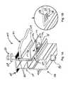
- FIG. 1Aillustrates a rail assembly for use as part of a larger solar module mounting assembly, according to an embodiment of the invention.
- FIG. 1Bis a close-up of a portion of the conductive element of FIG. 1A , under an embodiment of the invention.
- FIG. 2Aillustrates a bonding clip for use as a conductive element, in accordance with an embodiment of the invention.
- FIG. 2Bis a frontal view of clip of FIG. 2A , along lines A-A, under an embodiment of the invention.
- FIG. 2Cillustrates an embodiment in which an alternative clip is provided, according to an embodiment of the invention.
- FIG. 3is an exploded side view of a rail assembly configured to include one or more bonding features, under another embodiment of the invention.
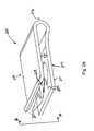
- FIG. 4illustrates another rail assembly configuration for promoting electrical bonding in a mounting system, under an embodiment of the invention.
- FIG. 5illustrates another rail assembly configuration for promoting electrical bonding in a mounting system, under an embodiment of the invention.
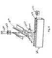
- FIG. 6is an exploded view of a mounting assembly that includes a strut runner, under an embodiment of the invention.
- FIG. 7illustrates a mounting assembly, under an embodiment of the invention.
- Embodiments described hereinenable use of conductive elements on mounting assemblies for solar modules, for purpose of creating bonding or grounding points. As described, embodiments provide that such conductive elements are included between the engagement of the solar modules and the rail assemblies or support structures that hold the solar modules in place. Conductive paths for bonding or grounding purposes may then be formed that require minimal additional steps in assembling the mounting assembly as a whole. One or more embodiments enable such bonding or grounding features to be incorporated into the solar module array with assembly steps that eliminate the need for running grounding/bonding elements as separate assembly requirements.
- a mounting systemfor an array of solar modules.
- the mounting systemincludes one or more rail assemblies that extend lengthwise in a first direction to support a plurality of solar modules that comprise the array.
- Each of the one or more rail assembliesmay be configured to compress in order to retain an edge section of one or more of the plurality of solar modules in an operable position.
- a conductive elementmay be positioned to bond the edge section of at least one of the plurality of solar modules with at least a section of the rail assembly that retains that edge section in the operable position, so as to form a conductive path for electrical current.
- the conductive pathsmay extend from the edge section to at least the one or more rail assemblies.
- CCRCommon Compressed Rail
- FIG. 1Aillustrates a rail assembly for use as part of a larger solar module mounting assembly, according to an embodiment of the invention.
- conductive elementsmay be included or used with a rail assembly 100 to enable the passage of electrical current between one or more solar module frames and the mounting system. Enabling the passage of electrical currents in a manner provided for by embodiments described herein enables a mounting assembly or system to handle, for example, electrical shorts on individual solar modules, lightening strikes, or other events which can be dangerous or harmful to equipment.
- a mounting assemblygenerally includes solar modules, rail assemblies, and strut runners.
- the solar modulesinclude a combination of a solar panel and a frame that holds the solar panel.
- the panelitself may include solar cells or other solar-sensitive material such as a thermal absorber.
- the rail assembliesprovide a primary support for retaining solar modules in position.
- U.S. patent application Ser. Nos. 10/855,254 11/332,000(both of which are hereby incorporated by reference in their respective entirety) for example, illustrate the use and context of a rail assembly for use in retaining and supporting solar modules in operable positions to receive sunlight.
- the strut runnersinterconnect the rail assemblies and provide support for the rail assemblies by securing the rail assemblies to an underlying structure (such as a roof top).
- the rail assembly 100is structured to retain a solar module in an operable position (i.e. directed to receive sunlight).
- the solar module 101includes a frame 104 and a panel 109 having solar sensitive materials.
- the rail assembly 100includes a top rail section 105 and a bottom rail section 106 that combine to form a receiving structure 122 .
- the top and bottom rail sections 105 , 106are compressed while an edge section 126 of the frame 104 of the solar module 101 is inserted or retained with the receiving structure 122 .
- the receiving structure 122may include a ledge surface 124 , which in an embodiment shown is provided by the bottom rail section 106 . Absent intermediate structures described herein, the top rails section 105 is compressed into the bottom rail section 106 to tighten a dimension of the receiving structure 122 , and cause the receiving structure 122 to grip the frame 104 against the ledge surface 124 .
- a conductive element 102is positioned between the frame 104 and the rail assembly 100 .
- the conductive element 102is sandwiched between the frame and the ledge surface 124 , where the active compression force for compressing the top and bottom rail structures 105 , 106 is in effect.
- the conductive element 102is provided as a thickness over the ledge surface 124 (to be between the frame 104 and the ledge surface 124 ).
- the conductive element 102is a clip extending on an underside of the frame 104 . The clip formation of conductive element 102 may enable it to grip with bias an edge 114 of the frame 104 .
- a strip 115may extend underneath the frame 104 , so as to be positioned over the ledge surface 124 .
- a protrusion 135may be positioned on the strip 115 so as to be in contact with the ledge surface 124 when the top and bottom rail sections 105 , 106 are under compression.
- a structure 132may receive the bolt 130 .
- the receiving structure 132is in the form of a captive nut formed from metal such as steel.
- a washer 133may be used under the bolt 130 to spread the compressive force.
- the washer 133may be serrated to promote electrical bonding between the bolt 130 and the top rail structure 105 .
- the receiving structure 132may take several forms, including the form of a threaded insert. Alternatively, structure 132 may be formed directly on the bottom rail structure 106 through a drilling and tapping process such that it is electrically bonded to the lower mounting rail 106 .
- compressionWhen tightened, compression is applied through bolt 130 and receiving structure 132 .
- the compressionmay act to reduce a dimension of the receiving structure 122 , thereby forcing the frame 104 against the ledge surface 124 .
- the conductive element 102is compressed between the frame 104 and the ledge surface 124 , with the protrusion 135 being bonded with the ledge surface 124 .
- a resulting conductive pathis provided from the frame 104 to the rail assembly 100 to enable passage of electrical current for bonding the frame to the rail assembly.
- the rail assembly 100may be interconnected to other components to enable grounding of the elements within the solar array.
- FIG. 1Billustrates that the thickness of the conductive element may have varying dimensions when provided on the ledge surface 124 .
- the thicknessshown in the form of protrusion 135 , includes a peak 134 and a trough 136 (thus defining one or more peaks).
- the peak 134 and trough 136may be visually distinguishable, so as to be vertically separated by a distance that is greater than 1 mm.
- FIG. 2Aillustrates a bonding clip 210 for use as a conductive element, in accordance with an embodiment of the invention.
- the bonding clip 210may include multiple bonding features 205 designed to enable or enhance electrical contact between an underside of the frame 104 ( FIG. 1A ) and the ledge surface 124 ( FIG. 1A ).
- the clip 210includes a first panel 212 that is joined with a second panel 214 via a radius bend 216 .
- a gap 218is defined in the structure for gripping the edge of the frame 104 .
- the radius bend 216enables the panels 212 , 214 to be biasely separated, so as to increase a dimension of the gap 218 .
- the dimension of the gap 218may be designed so that when the clip 210 is in an unbiased state, the gap 218 is less than a dimension of the thickness of the edge 114 .
- the clip 210can be biasely enlarged to positively grip the edge 114 of frame 104 and remain in position.
- bonding features 205may be in the form of teeth or protrusions that grip into one of the surfaces of the frame.
- the bonding features 205may be provided on one or both inner surfaces 207 , 209 provided by panels 212 , 214 .
- One of the exterior surfaces 211may also include bonding features 215 (shown in FIG. 2B ) to bond with the ledge surface 124 of the receiving structure 122 .
- FIG. 2Bis a frontal view of clip 210 , along lines A-A, under an embodiment of the invention.
- bonding features 205may be provided on an interior surface 207 that partially defines gap 218 along with interior surface 209 .
- the panels 212 , 214may biasely separate to increase dimension of gap 218 , enabling the edge 114 of frame 104 to be inserted therein.
- a lower bonding feature 215is extended from clip 210 .
- the lower bonding features 215bonds to the ledge surface 124 .
- the lower bonding features 215is also sharpened to tooth-shaped to enhance the bond under compression. Sharpened features such as shown by bonding features 205 , 215 also provide added benefit of penetrating through any coated surface that may be provided on either the frame 104 or ledge surface 124 , including paint, anodization, or corrosion.
- bonding features 205 , 215may be formed during the die stamping process used to fabricate the clip 210 .
- Other implementations of the protrusionsare also possible and may range from raised and pointed cones to the sharp open barbs found on fine grating devices.
- the bonding features 205 , 215may be formed such that an enclosed contact area is formed to specifically exclude introduction of air or moisture that could oxidize the contact area and inhibit the electrical bond.
- One purpose of the bonding features 205 , 215includes penetration of any coatings on the mating surfaces to provide good and constant electrical contact between the frame 104 and the rail assembly 100 (or other portion of a larger mounting assembly). This can be achieved though a multitude of features and should not be restricted to those outlined above.
- clip 210may serve an additional purpose of retaining any wiring in the solar array, such as interconnections between solar PV modules.
- the use of such a featurehides the wires from view for a more aesthetically pleasing array and may prevent the wires from abrading over time due to the wind brushing the wires against a roof or the mounting system itself.
- FIG. 2Cillustrates an embodiment in which an alternative clip 260 is shaped to contain a wire-holding loop 270 .
- the wire-holing loopmay be configured to retain any wiring within the solar array.
- the remotely located wire-holding loop 270is separated from a main body 262 of the clip 260 by a bridge 264 , which allows any wires to be inserted after the bonding clip 260 has been installed.
- rail assembly 100may not require a ledge surface 124 , but rather may compress the frame 104 using other features of the receiving structure 122 .
- any of the conductive elements (including clips 210 , 26 ) described abovemay be provided for the frame 104 compressing against some other structure of the top or bottom rail section 105 , 106 or receiving structure 122 .
- the frame 104may include only vertical flanges as opposed to edge 114 , in which case the conductive element (or one of the clips 210 , 260 ) may be relocated for intimate contact during the compression.
- one possible arrangementincludes placing alternative bonding features on radius bend 216 of the clip 210 , so that when the clip is installed on a vertically aligned flange, the alternative bonding features are forced into contact with a surface of the bottom rail section 106 ( FIG. 1A ).
- a clipmay be positioned between the frame 104 and the top rail section 105 to provide electrical contact.
- strut runnersmay form part of an overall mounting assembly that interconnects rail assemblies and secures rail assemblies to a rooftop or other underlying structure.
- One or more embodimentsprovide for use of strut runners to provide grounding or other forms of electrical bonding, in connection with bonding features described with other embodiments.
- the use of strut runnersenables, for example, electrical current caused from a shorted PV module or a lightening strike to be grounded or carried away from the mounting structure.
- Both the top rail section 105 ( FIG. 1A ) and bottom rail section 106 ( FIG. 1A )may be formed from extruded Aluminum, formed steel, or other electrically conducting material of sufficient cross section to act as electrical buss-bars. Such construction enables the formation of an electrical bond between separate solar modules arranged along their length.
- the use of bolt 130 to attain compression of the top and bottom rail sections 105 , 106 for each of multiple solar modules 101 in a columnmay be leveraged. More specifically, the column arrangement provides for multiple bolts 130 to also be aligned vertically with the rail sections.
- the bolts 130may provide electrical continuity between the top rail section 105 and bottom rail section 106 , so as to properly bond the entire mounting system and thus allowing current to freely pass between all members. This same regular pattern of bolts 130 assures sufficient pressure upon the solar module frames to compress the conductive elements 102 ( FIG. 1A ), which as described with FIG. 2A and FIG. 2C , may correspond to clips 210 or clips 260 .
- FIG. 3is an exploded side view of a rail assembly configured to include one or more bonding features, under another embodiment of the invention.
- rail structure 300may, as described with an embodiment of FIG. 1A , include a top rail section 305 that compresses against a bottom rail section 306 .
- the combined rail sections 305 , 306may form the receiving structure that includes the ledge surface 324 .
- the compression mechanismis provided by the bolt 330 , which secures into receiving structure 332 .
- Washer 333may be used under bolt 330 to spread the compressive force.
- one or more embodimentsprovide for use of conductive elements 302 to electrically bond the frame 304 of the solar module 301 and the rail assembly 300 .
- the conductive elements 302are in the form of a strip 310 .
- FIG. 3illustrates another rail assembly configuration for promoting electrical bonding in a mounting system, under an embodiment of the invention.
- an embodiment of FIG. 3provides for use of a bonding strip 310 to electrically bond (and protect) a mounting assembly.
- the bonding strip 310is a thickness of material that is placed between the solar module frame 304 and the top and bottom rails structures 305 , 306 .
- the bonding strip 310may contain multiple sharp protrusions 302 on both a top and bottom surface 311 , 313 . These protrusions 302 may penetrate the surfaces of the solar module frame 304 and corresponding top or bottom rail sections 305 , 306 .
- the sharp protrusions 302penetrate any coatings on the solar module frame 304 , as well as on the particular top or bottom rail section 305 , 306 that is contact. The result is the establishment of a secure electrical bond for the passage of electrical current.
- the bonding strip 310is shown placed on both sides of the solar module frame 304 , an alternative embodiment may employ only a single bonding strip 310 .
- the bonding strip 310may be employed on just the bottom rail section 306 , or just the top rail section 305 .
- the bonding strip 310may be formed through any one of many possible processes.
- One possible processincludes using a die punch or to roll form a metal strip that integrally forms the protrusions 302 in forms analogous to those used in the bonding clip of FIGS. 2A-2C .
- conductive studscould be embedded into a polymer or rubber strip wherein the studs protrude from both sides of the bonding strip 310 . In such a case, only the studs need to be conductive and the strip itself is just a carrier that can be made from conductive or non-conductive materials.
- Another possible processis to utilize commercially available contact strips such as the MULTILAM product series manufactured by MULTI-CONTACT of Santa Rosa, Calif. among others.
- FIG. 4illustrates another rail assembly configuration for promoting electrical bonding in a mounting system, under an embodiment of the invention.
- an embodiment of FIG. 4provides for use of discrete bonding pins 410 instead of, for example, the strip 310 .
- the rail assembly 400is shown to have a construction described with an embodiment of FIG. 1A or FIG. 3 .
- the bonding pins 410include conductive points that are fastened to the solar module frame 404 , or alternatively to the top and bottom rail sections 405 , 406 . When the top and bottom rail sections 405 , 406 are compressed by the bolt 430 , the bonding pins 410 penetrate into the solar module frame 404 and/or top and bottom rail sections 405 , 406 .
- the bonding pins 410are in the form of barbed or press fitted metal studs that provide intimate electrical contact.
- the bonding pinsmay take the form of blind rivets wherein the rivet head is barbed or otherwise enhanced to provide contact and pierce insulators on the opposed mounting surface.
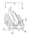
- FIG. 5illustrates another rail assembly configuration for promoting electrical bonding in a mounting system, under an embodiment of the invention.
- an embodiment of FIG. 5provides for use of sharp internal bonding features 510 , instead of, for example, the discrete bonding pins 410 ( FIG. 4 ) or the strip 310 ( FIG. 3 ).
- the rail assembly 500is shown to have a construction described with other embodiments provided for herein.
- the sharp internal bonding feature 510may be provided to be integral to the cross-section of the bottom rail section 506 , regardless of whether the rails have been extruded, rolled, or formed by other means. Such bonding features 510 may be designed to penetrate into the solar module frame 504 when the mounting system is compressed.
- the bonding features 510may be made continuous, as through an extrusion or rolling process.
- the bonding featuresare enhanced by a secondary machining or grinding process that removes material to yield intermediate gaps 502 and thereby create the discrete bonding features 510 illustrated in FIG. 5 .
- the benefit of utilizing discrete bonding features 510 over a continuous bonding featureis that the discrete bonding features reduce line contact features to point contacts.
- One or more embodimentsprovide that alternative forms of rail enhancement are used to provide integrated bonding features.
- the surfaces of the top and bottom rail sections 105 , 106may be pierced using dies to create a sharp protrusion on, for example, the ledge surface 124 ( FIG. 1A ).
- die workis performed on the ledge surface 124 to create sharp louvers analogous to the features 205 of bonding clip 210 (see FIG. 2A ).
- a drilling proceduremay lift material out of the hole to create a sharp raised collar, such as can be achieved through thermal drilling and other collaring equipment.
- FIG. 6is an exploded view of a mounting assembly that includes a strut runner, under an embodiment of the invention.
- a lower rail section 606 of a rail assemblymay include a base surface 608 that secures to a strut runner 610 .
- the bolt 630may extend through an opening 609 of the base surface 608 , so as to be received by structures that engage the strut runner 610 .
- the lower rail section 606(and this rail assembly) may extend in an orthogonal direction as compared to the direction of the strut runner 610 .
- the strut runner 610may include a slot 612 that receives an attachment bolt 630 , extending from the bottom rail section 606 .
- the attachment bolt 630is separate from a compression bolt or mechanism used with the rail assembly.
- the bolt 630may be received by a washer mechanism 620 , which engages slot 612 , to enable the bottom rail section 606 to secure to the strut runner 610 .
- the slot 612may also hold a strut nut 622 for receiving and retaining the bolt 630 .
- the bottom rail section 606is then secured to the strut runner 610 through a tightening of the bolt 630 and strut nut 622 .
- the strut runner 610may secure to the underlying structure so as to retain the rail assembly in place. Multiple strut runners may be used in one mounting assembly to hold multiple rail assemblies in position. The resulting assembly may retain solar modules in series and/or in parallel, and/or in column and row-wise alignment.
- the washer mechanism 620may incorporate a hole 619 for passage of the bolt 630 .
- the washer mechanism 620may additionally contain sharp protrusions 624 designed to promote electrical contact between the strut runner 610 and bottom rail section 606 when compression is present from bolt 630 and strut nut 622 . As such, protrusions 624 may be provided on both the top and bottom surface of the washer mechanism 620 (bottom surface not shown).
- the washer 633may take the form of a serrated or toothed washer capable of bonding the bottom rail section 606 to bolt 630 .
- the bolt 630may maintain electrical contact to strut nut 622 through the threaded interface, and the strut nut 622 may be bonded to the strut runner 610 through protrusions that engage the strut runner 610 during compression.
- strut runner 610has been used to describe the structural and electrical attachment of the bottom rail section 606
- alternate implementations and designsmay use other members that are capable of achieving the same or similar effect.
- structural channel, beams, bar, or other membersmay be used with appropriate fasteners.
- the strut runner 610should simply be viewed as an illustrative embodiment for securing a rail assembly or a section thereof.
- FIG. 7illustrates a mounting assembly 700 comprising a set of strut runners 712 , 722 and a set of mounting rails, under an embodiment of the invention.
- rail assembliesare assumed to have a construction such as described with, for example, an embodiment of FIG. 1A .
- Mounting rail assemblies 710 , 720 , and 730include both top and bottom rail sections.
- the mounting assembly 700holds multiple solar panels 742 , 744 , 746 , 748 .
- the solar panelsmay individually comprise only one element of a solar module that has both panel and frame. For simplicity, only the panels of the solar modules are shown in FIG. 7 .
- the mounting rail assemblies 710 , 720 , 730may be secured at fixed distances from each other to provide for the width of the solar panels 742 , 744 , 746 , 748 and their associated frames 104 ( FIG. 1A ), such that they may be compressed and retained on a common edge.
- Strut runners 712 , 722provide such a fixed spacing within the mounting system when the lower rail sections are secured to the strut runners, as illustrated by FIG. 6 .
- Numerous variationsare possible to the mounting assembly 700 .
- the strut runners 712 , 722are shown as continuous members, they may be deployed as shorter discrete sections secured to an underlying surface such as a roof.
- the strut runners 712 , 722may also provide electrical bonding between adjacent rail assemblies within the mounting system. Assuming the strut runners are fabricated from a metal or other electrically conductive material then the electrical bond between each rail set 710 , 720 , 730 and the corresponding strut runner 712 , 722 is communicated to the other rail assemblies utilizing the strut runner as the common conductor or buss bar.
- the set provided by panels 742 and 748may be connected as columns, as well as the set provided by panels 744 and 746 .
- conductive elements 102FIG.
- Directional arrow 752illustrates such a conductive path, which can occur at discrete locations on the mounting assembly 700 , coinciding with placement of conductive elements, as described with any of the embodiments provided for herein. Under an embodiment such as described with FIG. 6 , the conductive path between one of the rail assemblies 720 , 720 , 730 is further extended to the connected strut runner 712 , 722 .
- Directional arrow 754illustrates such a conductive path, which enables the rail assemblies to use the strut runners 712 , 722 as buss bars.
- the strut runners 712 , 722may ground or direct the current away from the mounting assembly, as illustrated by the directional arrow 756 .
- conductive pathsmay be defined by the directional arrows 752 , 754 and/or 756 .
- one or more embodimentsprovide the solar module assembly as a whole may be discontinuous, or assembled in discrete sections.
- the strut runners and the rail assembliesmay be electrically discontinuous.
- electrical continuity for bondingmay be achieved by, for example, extending a wire or other conductor between discrete strut runners or between discrete sections of the assembly as a whole.
- the same effectmay be achieved if solar modules at each discrete section are bonded to each rail assembly on each of their respective edge section.
- the bonding between one solar module and both rail assemblies of that solar modulemay provide the electrical continuity that may otherwise be absent amongst the discrete sections.
- a common bonding point 760may be used to bond (or ground) the entire mounting system 700 , inclusive of strut runners, mounting rail sets, ancillary hardware, and solar modules through a conductor 770 to a designated point such as a grounding rod or other location.
- conductive paths illustrated by the directional arrows 752 (frame to rail assembly), 754 (rail assembly to strut runner) and 756 (along strut runner)may carry to the conductor 770 via the point 760 .
- bonding point 760may be used to commonly bond all elements within a solar array including the mounting system and solar modules.
- each rail assembly 710 , 720 , 730may be bonded to strut runner 712 .
- An embodiment such as described with FIG. 6may be used to bond the strut runner 712 to the rail assemblies.
- Each of the bottom rail sections 106may be bonded to the corresponding top rail sections 105 through compression bolts 130 and receiving structures 132 .
- each solar module 101may be bonded to one or more rail assemblies through any of the embodiments described above.
- the solar module frame 104( FIG. 1A ) may be electrically bonded to a single rail assembly when it is in physical contact with two since one or more of the underlying strut runners 712 , 722 are capable of bonding adjacent rail assemblies.
- solar modules placed in column alignment(as shown by panels 742 and 748 ) may be bonded together by the rail assemblies, while solar modules aligned in rows (as shown by panels 742 and 744 ) may be bonded by the strut runners 712 , 722 .
- a single bonding point 760is sufficient to bond all elements within the assembly 700 . If desired and for sake of redundancy, a second bonding point (in addition to bonding point 760 ) may be established on strut runner 712 , or any conductive element within the array.
Landscapes
- Engineering & Computer Science (AREA)
- Chemical & Material Sciences (AREA)
- Mechanical Engineering (AREA)
- Sustainable Development (AREA)
- Sustainable Energy (AREA)
- Thermal Sciences (AREA)
- Physics & Mathematics (AREA)
- Combustion & Propulsion (AREA)
- Life Sciences & Earth Sciences (AREA)
- General Engineering & Computer Science (AREA)
- Architecture (AREA)
- Civil Engineering (AREA)
- Structural Engineering (AREA)
- Photovoltaic Devices (AREA)
- Roof Covering Using Slabs Or Stiff Sheets (AREA)
Abstract
Description
Claims (5)
Priority Applications (1)
| Application Number | Priority Date | Filing Date | Title |
|---|---|---|---|
| US11/848,766US8806813B2 (en) | 2006-08-31 | 2007-08-31 | Technique for electrically bonding solar modules and mounting assemblies |
Applications Claiming Priority (2)
| Application Number | Priority Date | Filing Date | Title |
|---|---|---|---|
| US82426006P | 2006-08-31 | 2006-08-31 | |
| US11/848,766US8806813B2 (en) | 2006-08-31 | 2007-08-31 | Technique for electrically bonding solar modules and mounting assemblies |
Publications (2)
| Publication Number | Publication Date |
|---|---|
| US20080053517A1 US20080053517A1 (en) | 2008-03-06 |
| US8806813B2true US8806813B2 (en) | 2014-08-19 |
Family
ID=39136960
Family Applications (1)
| Application Number | Title | Priority Date | Filing Date |
|---|---|---|---|
| US11/848,766Active2029-12-03US8806813B2 (en) | 2006-08-31 | 2007-08-31 | Technique for electrically bonding solar modules and mounting assemblies |
Country Status (3)
| Country | Link |
|---|---|
| US (1) | US8806813B2 (en) |
| EP (1) | EP2092136A4 (en) |
| WO (1) | WO2008028151A2 (en) |
Cited By (62)
| Publication number | Priority date | Publication date | Assignee | Title |
|---|---|---|---|---|
| US20130102165A1 (en)* | 2011-08-29 | 2013-04-25 | A. Raymond Et Cie | Universal clip apparatus for solar panel assembly |
| US20130335877A1 (en)* | 2011-03-11 | 2013-12-19 | Mobasolar Sas | Separate connection device for grounding electrical equipment comprising a plurality for separate electrical components |
| US20140109496A1 (en)* | 2012-10-18 | 2014-04-24 | Kevin Stapleton | Panel mounting bracket for standing seam roof and related methods |
| US20140151312A1 (en)* | 2009-03-20 | 2014-06-05 | Northern States Metals Company | Support system for solar panels |
| US20140220834A1 (en)* | 2013-02-04 | 2014-08-07 | Dynoraxx, Inc. | Solar panel grounding system and clip |
| US20140319307A1 (en)* | 2013-04-29 | 2014-10-30 | Sunmodo Corporation | Thermal Expansion Compensation Apparatus for Mounting Solar Panels |
| US20140338273A1 (en)* | 2013-05-16 | 2014-11-20 | Kevin Stapleton | Solar panel roof mounting bracket and related methods |
| US20150075590A1 (en)* | 2009-07-02 | 2015-03-19 | Zep Solar Llc | Pivot-fit frame, system and method for photovoltaic modules |
| US20150129517A1 (en)* | 2013-11-14 | 2015-05-14 | Ecolibrium Solar, Inc. | Modular Sloped Roof Solar Mounting System |
| US20160079909A1 (en)* | 2014-09-17 | 2016-03-17 | Lumos Lsx, Llc | Photovoltaic panel mounting system |
| US9431953B2 (en) | 2014-10-31 | 2016-08-30 | Rillito River Solar, Llc | Height adjustment bracket for roof applications |
| US9447988B2 (en) | 2010-01-25 | 2016-09-20 | Rillito Rive Solar, LLC | Roof mount assembly |
| US9455662B2 (en)* | 2015-01-27 | 2016-09-27 | Ironridge, Inc. | Assembly for locking and grounding solar panel modules to mounting components |
| US9647433B2 (en)* | 2014-11-19 | 2017-05-09 | Ironridge, Inc. | Rail-less solar panel assembly and installation method |
| USD800544S1 (en) | 2016-04-25 | 2017-10-24 | Unirac Inc. | Tri-drive nut |
| USD803040S1 (en) | 2016-04-25 | 2017-11-21 | Unirac Inc. | Helical drive |
| USD815308S1 (en) | 2016-11-15 | 2018-04-10 | Unirac Inc. | Trimrail extrusion |
| US9973142B2 (en) | 2013-03-06 | 2018-05-15 | Vermont Slate and Copper Services, Inc. | Snow fence for a solar panel |
| US9985575B2 (en) | 2014-04-07 | 2018-05-29 | Rillito River Solar, Llc | Height adjustment bracket for roof applications |
| USD824047S1 (en) | 2016-10-13 | 2018-07-24 | Unirac Inc. | Floating splice extrusion |
| USD827157S1 (en) | 2016-10-13 | 2018-08-28 | Unirac Inc. | Base extrusion |
| US10158321B2 (en)* | 2017-01-03 | 2018-12-18 | Solarcity Corporation | Photovoltaic mounting system |
| US10167891B1 (en)* | 2018-03-08 | 2019-01-01 | International Business Machines Corporation | Self-reporting, grounded nut-clip |
| US10256768B2 (en)* | 2016-04-25 | 2019-04-09 | Cmco Solar, Llc | Photovoltaic array mounting structure |
| US20190131918A1 (en)* | 2017-11-01 | 2019-05-02 | Yanegijutsukenkyujo Co., Ltd. | Panel member securing structure and panel member securing tool |
| US10291176B2 (en)* | 2013-12-13 | 2019-05-14 | Jobdog, Llc | Rail-less roof mounting system |
| US20190158012A1 (en)* | 2016-07-05 | 2019-05-23 | Solar Frontier K.K. | Securing Fixture for Photovoltaic Cell Module |
| US10312853B2 (en) | 2015-03-11 | 2019-06-04 | Ecolibrium Solar, Inc | Sloped roof solar panel mounting system |
| US10340838B2 (en) | 2015-08-03 | 2019-07-02 | Unirac Inc. | Hybrid solar panel mounting assembly with a tilted ledge |
| US10340837B2 (en) | 2015-03-11 | 2019-07-02 | Ecolibrium Solar, Inc | Sloped roof solar panel mounting system |
| US10461682B2 (en) | 2015-08-03 | 2019-10-29 | Unirac Inc. | Height adjustable solar panel mounting assembly |
| US10594250B2 (en) | 2015-08-03 | 2020-03-17 | Unirac Inc. | Hybrid solar panel mounting assembly |
| US10605282B1 (en)* | 2017-10-09 | 2020-03-31 | Jonathan Young | Panel mounting device |
| US10622935B1 (en)* | 2019-04-06 | 2020-04-14 | Sunmodo Corporation | Rail-mounted bottom clamp for mounting solar panels to roofs and the like |
| US10756668B2 (en) | 2015-03-11 | 2020-08-25 | Ecouni, Llc | Universal sloped roof solar panel mounting system |
| US10819271B2 (en) | 2015-08-03 | 2020-10-27 | Unirac Inc. | Height adjustable solar panel mounting assembly with an asymmetric lower bracket |
| US11035126B2 (en) | 2011-02-25 | 2021-06-15 | Rmh Tech Llc | Mounting device for building surfaces having elongated mounting slot |
| US11041310B1 (en) | 2020-03-17 | 2021-06-22 | Rmh Tech Llc | Mounting device for controlling uplift of a metal roof |
| US11050383B2 (en) | 2019-05-21 | 2021-06-29 | Nextracker Inc | Radial cam helix with 0 degree stow for solar tracker |
| US11085188B2 (en)* | 2016-10-31 | 2021-08-10 | Rmh Tech Llc | Metal panel electrical bonding clip |
| US20210265938A1 (en)* | 2018-07-04 | 2021-08-26 | Sabic Global Technologies B.V. | Solar roof forming element, building, and method of forming a roof |
| US11121669B2 (en) | 2016-09-12 | 2021-09-14 | EcoFasten Solar, LLC | Roof mounting system |
| US11159120B2 (en) | 2018-03-23 | 2021-10-26 | Nextracker Inc. | Multiple actuator system for solar tracker |
| US11271518B2 (en) | 2018-11-08 | 2022-03-08 | OMCO Solar, LLC | Mounting bracket for mounting photovoltaic modules to torque tube beam |
| US11313591B1 (en) | 2017-09-11 | 2022-04-26 | Moti Atia | Universal clamp apparatus to accommodate solar panel frames with different thicknesses |
| US11333179B2 (en) | 2011-12-29 | 2022-05-17 | Rmh Tech Llc | Mounting device for nail strip panels |
| US11352793B2 (en) | 2020-03-16 | 2022-06-07 | Rmh Tech Llc | Mounting device for a metal roof |
| US11368005B2 (en) | 2014-11-19 | 2022-06-21 | Ironridge, Inc. | Wire management structure for a rail-less solar panel assembly |
| US20220193927A1 (en)* | 2020-06-26 | 2022-06-23 | Rosendin Electric, Inc. | Bracket usable for solar panel module installation |
| US11387771B2 (en) | 2018-06-07 | 2022-07-12 | Nextracker Llc | Helical actuator system for solar tracker |
| US11573033B2 (en) | 2016-07-29 | 2023-02-07 | Rmh Tech Llc | Trapezoidal rib mounting bracket with flexible legs |
| US11616468B2 (en) | 2018-03-21 | 2023-03-28 | Rmh Tech Llc | PV module mounting assembly with clamp/standoff arrangement |
| US11668332B2 (en) | 2018-12-14 | 2023-06-06 | Rmh Tech Llc | Mounting device for nail strip panels |
| US20230188084A1 (en)* | 2013-12-13 | 2023-06-15 | Wencon Development, Inc., Dba Quick Mount Pv | Waterproofing Mounting System for Attaching Solar Modules to a Roof |
| US11774143B2 (en) | 2017-10-09 | 2023-10-03 | Rmh Tech Llc | Rail assembly with invertible side-mount adapter for direct and indirect mounting applications |
| US20240056025A1 (en)* | 2022-08-10 | 2024-02-15 | Freedom Forever LLC | Multifunction spacer-wire clips for solar panels and related methods |
| US12107530B2 (en) | 2014-04-07 | 2024-10-01 | EcoFasten Solar, LLC | Height adjustment bracket for roof applications |
| US12203496B2 (en) | 2020-07-09 | 2025-01-21 | Rmh Tech Llc | Mounting system, device, and method |
| US12301159B2 (en) | 2014-11-13 | 2025-05-13 | Unirac Inc. | Modular sloped roof solar mounting system |
| USD1075493S1 (en) | 2022-07-06 | 2025-05-20 | Rmh Tech Llc | Clamp for a photovoltaic module mounting assembly |
| US12368405B1 (en)* | 2024-09-04 | 2025-07-22 | Sunmodo Corporation | Railless mounting system and devices for attaching solar modules to roofs |
| US12435906B1 (en) | 2022-11-23 | 2025-10-07 | Sunmodo Corporation | Rail-less solar panel devices and system for roofs and the like and methods for mounting same |
Families Citing this family (111)
| Publication number | Priority date | Publication date | Assignee | Title |
|---|---|---|---|---|
| US20100108118A1 (en)* | 2008-06-02 | 2010-05-06 | Daniel Luch | Photovoltaic power farm structure and installation |
| US7856769B2 (en) | 2004-02-13 | 2010-12-28 | Pvt Solar, Inc. | Rack assembly for mounting solar modules |
| US7900407B2 (en)* | 2004-02-13 | 2011-03-08 | Pvt Solar, Inc. | Interconnected solar module design and system |
| US8344239B2 (en)* | 2004-02-13 | 2013-01-01 | Pvt Solar, Inc. | Mechanism for mounting solar modules |
| US20090038668A1 (en)* | 2007-08-08 | 2009-02-12 | Joshua Reed Plaisted | Topologies, systems and methods for control of solar energy supply systems |
| US7721492B2 (en)* | 2006-09-06 | 2010-05-25 | Pvt Solar, Inc. | Strut runner member and assembly using same for mounting arrays on rooftops and other structures |
| US7857269B2 (en)* | 2006-11-29 | 2010-12-28 | Pvt Solar, Inc. | Mounting assembly for arrays and other surface-mounted equipment |
| DE202008017629U1 (en)* | 2008-09-03 | 2010-04-22 | Sapa Gmbh | Solar module frame with water drain |
| WO2010045129A2 (en)* | 2008-10-11 | 2010-04-22 | Solar Power, Inc. | Efficient installation solar panel systems |
| US20100089390A1 (en)* | 2008-10-13 | 2010-04-15 | Sunlink, Corp | Solar array mounting system |
| US11063553B2 (en) | 2008-11-17 | 2021-07-13 | Kbfx Llc | Solar carports, solar-tracking carports, and methods |
| US10277159B2 (en)* | 2008-11-17 | 2019-04-30 | Kbfx Llc | Finished multi-sensor units |
| DE202009013609U1 (en)* | 2008-12-05 | 2010-04-22 | Climasol-Solaranlagen Gmbh | System for fixing a solar module, and arrangement of solar modules |
| JP5168406B2 (en)* | 2009-03-18 | 2013-03-21 | 富士電機株式会社 | Solar cell module |
| US8256169B2 (en) | 2009-03-20 | 2012-09-04 | Northern States Metals Company | Support system for solar panels |
| US8316590B2 (en)* | 2009-03-20 | 2012-11-27 | Northern States Metals Company | Support system for solar panels |
| US8240109B2 (en)* | 2009-03-20 | 2012-08-14 | Northern States Metals Company | Support system for solar panels |
| US8495997B1 (en)* | 2009-04-10 | 2013-07-30 | MBL & Sons, Inc. | Solar panel clip and method for attaching a solar panel |
| JP4465406B1 (en)* | 2009-04-16 | 2010-05-19 | 株式会社屋根技術研究所 | Connecting member |
| FR2948956B1 (en)* | 2009-08-05 | 2011-10-14 | Solarcom France | DEVICE FOR THE INSTALLATION OF A COVER INCLUDING SOLAR PANELS |
| EP2309552A1 (en)* | 2009-10-07 | 2011-04-13 | Carl Freudenberg KG | Clamping holder and fixing device for fixing plate like construction elements and method for producing the fixing device |
| US20110108093A1 (en)* | 2009-11-12 | 2011-05-12 | General Electric Company | Frame assembly for a photovoltaic panel |
| JP4979760B2 (en)* | 2009-12-24 | 2012-07-18 | シャープ株式会社 | Solar cell module mount and solar power generation system using the solar cell module mount |
| US8595996B2 (en)* | 2010-02-26 | 2013-12-03 | General Electric Company | Photovoltaic framed module array mount utilizing asymmetric rail |
| US10054336B2 (en)* | 2010-03-03 | 2018-08-21 | Robert M. M. Haddock | Photovoltaic module mounting assembly |
| US8816186B2 (en)* | 2010-04-09 | 2014-08-26 | John Christopher LeMay | Pre-fabricated non penetrating photovoltaic-support mechanism |
| US9462734B2 (en) | 2010-04-27 | 2016-10-04 | Alion Energy, Inc. | Rail systems and methods for installation and operation of photovoltaic arrays |
| US8757567B2 (en) | 2010-05-03 | 2014-06-24 | Sunpower Corporation | Bracket for photovoltaic modules |
| DE202010006442U1 (en)* | 2010-05-04 | 2010-08-19 | Ideematec Deutschland Gmbh | Frame for fixing solar modules |
| DE102010023212A1 (en)* | 2010-06-09 | 2011-12-15 | Schletter Gmbh | Support profile of a series of PV modules |
| EP2597682B1 (en)* | 2010-07-20 | 2017-09-06 | Kyocera Corporation | Solar cell array |
| US20110138599A1 (en)* | 2010-07-29 | 2011-06-16 | John Bellacicco | Mounting system supporting slidable installation of a plurality of solar panels as a unit |
| US20120111393A1 (en)* | 2010-07-29 | 2012-05-10 | Joshua Conley | Integrated cartridge for adhesive-mounted photovoltaic modules |
| US8455752B2 (en)* | 2010-07-29 | 2013-06-04 | General Electric Company | Integral ac module grounding system |
| US20120023726A1 (en)* | 2010-07-29 | 2012-02-02 | John Bellacicco | Method and apparatus providing simplified installation of a plurality of solar panels |
| US9343592B2 (en) | 2010-08-03 | 2016-05-17 | Alion Energy, Inc. | Electrical interconnects for photovoltaic modules and methods thereof |
| US8544221B2 (en)* | 2010-09-23 | 2013-10-01 | Hyperion Systems Llc | Adjustable racking system for solar array and method of construction of a solar array |
| FR2965671A1 (en)* | 2010-10-01 | 2012-04-06 | Sunnco | Device for equalizing potential differences in different parts of solar panel assembly assembled on roof of apartment building for producing electric power, has flexible part opposed to relative movement of device with respect to support |
| US20120097816A1 (en)* | 2010-10-20 | 2012-04-26 | D Three Enterprises, Llc | Combination mounting and grounding clip |
| US20120124922A1 (en)* | 2010-11-18 | 2012-05-24 | Northern States Metals Company | Support system for carport with solar panels |
| WO2012082806A2 (en) | 2010-12-13 | 2012-06-21 | Zep Solar, Inc. | Discrete attachment point apparatus and system for photovoltaic arrays |
| US20120174967A1 (en)* | 2011-01-10 | 2012-07-12 | NuvoSun, Inc. | Photovoltaic modules and mounting systems |
| US9450130B2 (en)* | 2011-01-27 | 2016-09-20 | Sunpower Corporation | Frame-mounted wire management device |
| DE102011010148A1 (en)* | 2011-02-02 | 2012-08-02 | Franz Öller | Electrically conductive and sealed connection structure of framed photovoltaic module, has module clamp that is screwed to substructure through anodized layer of module frame to obtain conductive connection between conductive elements |
| US8839573B2 (en)* | 2011-02-11 | 2014-09-23 | Northern States Metals Company | Spring clip |
| US9157665B2 (en)* | 2011-03-15 | 2015-10-13 | Richard William Erickson | Unitized photovoltaic assembly |
| US9641123B2 (en) | 2011-03-18 | 2017-05-02 | Alion Energy, Inc. | Systems for mounting photovoltaic modules |
| US20120255596A1 (en)* | 2011-04-05 | 2012-10-11 | General Electric Company | Photovoltaic mounting system with grounding bars and method of installing same |
| US8776454B2 (en) | 2011-04-05 | 2014-07-15 | Michael Zuritis | Solar array support structure, mounting rail and method of installation thereof |
| USD668214S1 (en) | 2011-04-27 | 2012-10-02 | Blue Sunny Skies Llc | Grounding clip |
| US9091461B2 (en)* | 2011-04-27 | 2015-07-28 | Blue Sunny Skies Llc | Grounding system for photovoltaic arrays |
| US8522493B1 (en)* | 2011-06-09 | 2013-09-03 | Randy William Rogers | Solar-power roof components and systems, and method of manufacturing same |
| US8955259B2 (en) | 2011-06-09 | 2015-02-17 | A. Raymond & Cie | Solar panel attachment system for a roof |
| US8946542B1 (en)* | 2011-06-24 | 2015-02-03 | Sunedison, Inc. | Solar module bonding method integrated into a pan structure |
| ITTO20110679A1 (en)* | 2011-07-27 | 2013-01-28 | Tarzia Daniele Denti | FIXING ELEMENT FOR SOLAR PANELS |
| US8590223B2 (en) | 2011-08-29 | 2013-11-26 | A. Raymond Et Cie | Solar panel assembly attachment apparatus |
| US9038329B2 (en) | 2011-10-11 | 2015-05-26 | Sunlink Corporation | Structure following roof mounted photovoltaic system |
| US8745935B2 (en)* | 2011-10-14 | 2014-06-10 | A. Raymond Et Cie | Photovoltaic panel fastening system |
| US20130161457A1 (en)* | 2011-10-17 | 2013-06-27 | Lumos Lsx, Llc | Photovoltaic module mounting system |
| US8701372B2 (en) | 2011-12-02 | 2014-04-22 | Cooper Technologies Company | Clip fastener for photovoltaic system |
| US20130139870A1 (en) | 2011-12-02 | 2013-06-06 | Cooper Technologies Company | Pier connection sytem for pier caps of photovoltaic system |
| WO2013082125A1 (en)* | 2011-12-02 | 2013-06-06 | Cooper Technologies Company | Photovoltaic system, racking assembly, module rail, clip fastener and method for assembling a photovoltaic system |
| US8726587B2 (en) | 2011-12-02 | 2014-05-20 | Cooper Technologies Company | Module rail for photovoltaic system |
| US9698724B2 (en)* | 2011-12-13 | 2017-07-04 | Solarcity Corporation | Connecting components for photovoltaic arrays |
| US9647157B2 (en) | 2011-12-13 | 2017-05-09 | Solarcity Corporation | Discrete attachment point apparatus and system for photovoltaic arrays |
| US8713881B2 (en) | 2012-01-27 | 2014-05-06 | A. Raymond Et Cie | Solar panel securing system |
| US9352941B2 (en) | 2012-03-20 | 2016-05-31 | Alion Energy, Inc. | Gantry crane vehicles and methods for photovoltaic arrays |
| DE102012009486A1 (en)* | 2012-05-09 | 2013-11-14 | K2 Systems Gmbh | Solar module holders |
| RU2014150870A (en) | 2012-05-16 | 2016-07-10 | Эйлион Энерджи, Инк. | ROTARY SUPPORT SYSTEMS FOR PHOTOELECTRIC MODULES AND RELATED METHODS |
| US9498854B2 (en) | 2012-06-25 | 2016-11-22 | Sunpower Corporation | Anchor for solar module |
| US9193014B2 (en) | 2012-06-25 | 2015-11-24 | Sunpower Corporation | Anchor for solar module |
| US9010041B2 (en) | 2012-06-25 | 2015-04-21 | Sunpower Corporation | Leveler for solar module array |
| US8943765B2 (en) | 2012-06-25 | 2015-02-03 | Sunpower Corporation | Brace for solar module array |
| US8683761B2 (en) | 2012-06-25 | 2014-04-01 | Sunpower Corporation | Mounting system for solar module array |
| US9976297B2 (en) | 2012-06-25 | 2018-05-22 | Sunpower Corporation | Anchor for solar module |
| KR20150034733A (en)* | 2012-06-25 | 2015-04-03 | 선파워 코포레이션 | Brace for solar module array |
| US9331629B2 (en) | 2012-07-02 | 2016-05-03 | A. Raymond Et Cie | Photovoltaic frame fastener |
| US10186791B2 (en) | 2012-07-05 | 2019-01-22 | Ironridge, Inc. | Assembly for clamping and grounding objects |
| US9689411B2 (en) | 2012-07-05 | 2017-06-27 | Ironridge, Inc. | Assembly for clamping and grounding objects |
| US20140021903A1 (en)* | 2012-07-18 | 2014-01-23 | Veka Inc. | Windows and doors having integrated solar powered charging devices |
| US9299868B2 (en) | 2012-10-01 | 2016-03-29 | Marc M. Thomas | Solar panel mounting and installation |
| US10256766B2 (en) | 2012-10-01 | 2019-04-09 | Marc M. Thomas | Solar panel installation and dimension compensating retention device |
| WO2014118840A1 (en)* | 2013-01-29 | 2014-08-07 | 三洋電機株式会社 | Solar cell module |
| US9065191B2 (en) | 2013-02-25 | 2015-06-23 | Hubbell Incorporated | Single fastener electrical connector |
| US9347691B2 (en)* | 2013-02-26 | 2016-05-24 | Solarcity Corporation | Torque Tube Mounted Photovoltaic Apparatus, System, and Method |
| US8888431B2 (en) | 2013-03-15 | 2014-11-18 | Hubbell Incorporated | Adjustable bonding washer |
| USD740113S1 (en) | 2013-03-15 | 2015-10-06 | Hubbell Incorporated | Clip-on bonding washer |
| US9303663B2 (en) | 2013-04-11 | 2016-04-05 | Northern States Metals Company | Locking rail alignment system |
| US9080792B2 (en) | 2013-07-31 | 2015-07-14 | Ironridge, Inc. | Method and apparatus for mounting solar panels |
| WO2015034863A1 (en) | 2013-09-05 | 2015-03-12 | Alion Energy, Inc. | Systems, vehicles, and methods for maintaining rail-based arrays of photovoltaic modules |
| US9453660B2 (en) | 2013-09-11 | 2016-09-27 | Alion Energy, Inc. | Vehicles and methods for magnetically managing legs of rail-based photovoltaic modules during installation |
| JP5915620B2 (en)* | 2013-10-23 | 2016-05-11 | ウシオ電機株式会社 | Solar cell module |
| US9397605B2 (en) | 2013-10-30 | 2016-07-19 | Kevin Stapleton | Panel mounting bracket with under-mounting clamp and related methods |
| US9276521B2 (en) | 2014-01-16 | 2016-03-01 | JSI Equipment Solutions LLC | Clamp for solar panel array |
| EP2924365A1 (en)* | 2014-03-24 | 2015-09-30 | Sadef N.V. | A profile for supporting a solar panel |
| JP6330203B2 (en)* | 2014-08-08 | 2018-05-30 | 株式会社動力 | Solar panel mounting device |
| US20170359020A1 (en) | 2014-12-11 | 2017-12-14 | A.K. Stamping Company, Inc. | Grounding Clamps |
| KR101562850B1 (en) | 2015-01-27 | 2015-10-26 | (주)한남전기통신공사 | Grounding clip for photovlotaic module |
| US10171027B2 (en)* | 2015-03-02 | 2019-01-01 | Sunpower Corporation | Photovoltaic module mount |
| CN104980094B (en)* | 2015-07-01 | 2017-09-05 | 江苏晨科新能源有限公司 | Solar bracket guide rail and its cooperating clamping block, middle pressing block and side pressing block |
| US9923511B2 (en)* | 2015-08-03 | 2018-03-20 | Jason Sen Xie | Connecting solar modules |
| US20160344338A1 (en)* | 2015-08-07 | 2016-11-24 | Everest Solar Systems, LLC | Profiled-Rail Retaining Element Having Protuberances for a Mechanical and Electrical Connection |
| WO2017044566A1 (en) | 2015-09-11 | 2017-03-16 | Alion Energy, Inc. | Wind screens for photovoltaic arrays and methods thereof |
| US12294332B2 (en) | 2015-12-15 | 2025-05-06 | Kbfx Llc | Solar carports, solar-tracking carports, and methods |
| WO2017182056A1 (en)* | 2016-04-19 | 2017-10-26 | Zimmermann Pv-Stahlbau Gmbh & Co. Kg | Counter-holder for pv module clamps for free-field systems |
| US10103688B2 (en)* | 2016-09-29 | 2018-10-16 | Sunpower Corporation | Systems and methods for improved installation and grounding of photovoltaic assemblies |
| JP7020815B2 (en)* | 2017-08-03 | 2022-02-16 | 株式会社Lixil | Solar power generator |
| CN112970193B (en) | 2018-10-08 | 2025-05-09 | 俄克拉何马大学董事会 | Systems for installing solar panels |
| US11545929B2 (en)* | 2019-02-07 | 2023-01-03 | United States Department Of Energy | Solar panel racking system |
| JP2020165280A (en)* | 2019-03-28 | 2020-10-08 | パナソニック株式会社 | Solar power generator |
| DE102019003390A1 (en)* | 2019-05-13 | 2020-11-19 | Schletter lnternational B.V. | Longitudinal profile and module clamp for a mounting system for solar modules and such a mounting system |
Citations (86)
| Publication number | Priority date | Publication date | Assignee | Title |
|---|---|---|---|---|
| US1159372A (en) | 1915-11-09 | Charles W Goff | Shingling-bracket. | |
| US1306434A (en) | 1919-06-10 | Philip p | ||
| US2747166A (en)* | 1954-12-13 | 1956-05-22 | Collins Radio Co | Interlocked flexible contact assembly for shaft |
| US3881799A (en)* | 1972-09-11 | 1975-05-06 | George H Elliott | Resilient multi-micro point metallic junction |
| US4029080A (en) | 1975-01-27 | 1977-06-14 | Westinghouse Electric Corporation | Thermal collector of solar energy adapted for high temperature operation |
| US4061413A (en)* | 1974-10-10 | 1977-12-06 | Siemens Aktiengesellschaft | Gasket for the high-frequency-tight connection of detachable metallic shielding elements |
| US4150660A (en) | 1977-09-15 | 1979-04-24 | Margot Elizabeth Peters | Easy access energy conversion panels for solar heating systems |
| US4239555A (en)* | 1979-07-30 | 1980-12-16 | Mobil Tyco Solar Energy Corporation | Encapsulated solar cell array |
| US4336413A (en) | 1979-09-10 | 1982-06-22 | R.T.C. La Radiotechnique Compelec | Solar panels |
| US4372292A (en) | 1981-04-14 | 1983-02-08 | Ort Sterling L | Method and apparatus for construction of a solar collector |
| US4636577A (en) | 1983-08-29 | 1987-01-13 | Thomas & Betts Corporation | Solar panel module and support therefor |
| US4936063A (en) | 1989-05-19 | 1990-06-26 | Humphrey John B | Frame flanges for mounting photovoltaic modules direct to roof structural framing |
| US4961712A (en)* | 1988-10-20 | 1990-10-09 | Schroff Gmbh | Mechanical and electrical connection between an extruded metal profile and a cast metal member |
| US4993959A (en)* | 1990-01-19 | 1991-02-19 | Amp Incorporated | Grounding clip |
| EP0417303A1 (en) | 1989-03-30 | 1991-03-20 | Hirai Engineering Corporation | Roof collecting solar energy |
| US5180442A (en)* | 1992-04-06 | 1993-01-19 | Eric Elias | Integration system for solar modules |
| EP0587348A2 (en) | 1992-09-07 | 1994-03-16 | Hirai Engineering Corporation | Roof apparatus |
| EP0599497A1 (en) | 1992-11-19 | 1994-06-01 | Hirai Engineering Corporation | Roof system utilizing a solar cell |
| US5338369A (en) | 1993-02-16 | 1994-08-16 | Rawlings Lyle K | Roof-integratable photovolatic modules |
| EP0614058A2 (en) | 1993-03-04 | 1994-09-07 | C.M.E. Schwarz Holdinggesellschaft M.B.H. | Device for collecting heat energy |
| US5409549A (en) | 1992-09-03 | 1995-04-25 | Canon Kabushiki Kaisha | Solar cell module panel |
| US5451167A (en)* | 1994-07-28 | 1995-09-19 | Illinois Tool Works Inc. | Grounding clip |
| US5524401A (en) | 1993-01-12 | 1996-06-11 | Misawa Homes Co., Ltd. | Roof with solar battery |
| US5571338A (en)* | 1993-11-26 | 1996-11-05 | Sanyo Electric Co., Ltd. | Photovoltaic module and a photovoltaic apparatus |
| US5603187A (en) | 1995-07-05 | 1997-02-18 | Merrin; William R. | Watertight system for mounting equipment on roof |
| JPH09184209A (en) | 1996-01-08 | 1997-07-15 | Sekisui Chem Co Ltd | Solar system house |
| US5687453A (en)* | 1995-04-17 | 1997-11-18 | Chrysler Corporation | Grounding washer and arrangements for conductive hinge joints |
| US5740996A (en) | 1995-08-09 | 1998-04-21 | Genschorek; Gido | Device for mounting plate-like construction components |
| JPH10159201A (en) | 1996-12-03 | 1998-06-16 | Sekisui Chem Co Ltd | Ventilation structure behind solar cell module juxtaposition body and ventilation structure of building provided with the structure |
| US5788204A (en) | 1996-09-26 | 1998-08-04 | Goodwin; Jeffrey G | Pump jack base |
| US5851309A (en) | 1996-04-26 | 1998-12-22 | Kousa; Paavo | Directing and concentrating solar energy collectors |
| EP0905795A2 (en) | 1997-09-24 | 1999-03-31 | Matsushita Electric Works, Ltd. | Mounting system for installing an array of solar battery modules of a panel-like configuration on a roof |
| JPH11186586A (en)* | 1997-12-22 | 1999-07-09 | Canon Inc | Panel fixing member, ground structure of solar cell panel, and grounding method thereof |
| US5924486A (en) | 1997-10-29 | 1999-07-20 | Tecom, Inc. | Environmental condition control and energy management system and method |
| JPH11204819A (en)* | 1998-01-07 | 1999-07-30 | Canon Inc | Solar power generator |
| DE19804685A1 (en) | 1998-02-06 | 1999-08-12 | Schaefer Wolfgang | Energy generating solar cell |
| US5986203A (en) | 1996-06-27 | 1999-11-16 | Evergreen Solar, Inc. | Solar cell roof tile and method of forming same |
| JP2000100490A (en)* | 1998-09-24 | 2000-04-07 | Matsushita Electric Works Ltd | Grounding structure for solar battery module |
| US6106310A (en)* | 1997-11-19 | 2000-08-22 | The Whitaker Corporation | Panel-grounding contact |
| US6195066B1 (en) | 1999-01-19 | 2001-02-27 | Thomas C. Pegues, Jr. | Satellite dish mounting arm |
| US6201179B1 (en) | 1997-10-03 | 2001-03-13 | Nick Dalacu | Array of photovoltaic modules for an integrated solar power collector system |
| US6269596B1 (en)* | 1997-02-05 | 2001-08-07 | Canon Kabushiki Kaisha | Roof member and mounting method thereof |
| JP2001214579A (en)* | 2000-01-31 | 2001-08-10 | Sanko Metal Ind Co Ltd | Earth structure in flat solar enclosure |
| US6283770B1 (en)* | 1998-12-11 | 2001-09-04 | Cisco Technology, Incc. | Minimal intrusion EMI shielding clip to maintain electrical contact between two parallel surfaces |
| JP2001262800A (en)* | 2000-03-15 | 2001-09-26 | Kanegafuchi Chem Ind Co Ltd | Photovoltaic power generation device |
| US6320120B1 (en)* | 1999-04-15 | 2001-11-20 | Laird Technologies | Low profile clip-on shielding strip |
| US6323478B1 (en) | 1997-10-30 | 2001-11-27 | Canon Kabushiki Kaisha | Photovoltaic power generation roof and installation method thereof |
| US6366304B1 (en)* | 1999-10-04 | 2002-04-02 | Fujitsu Limited | Thermal correction for image-forming exposure device and method of manufacturing the device |
| WO2002041407A1 (en) | 2000-11-16 | 2002-05-23 | Kaneka Corporation | Solar battery module, photovoltaic power generation system, support block supporting solar battery module, and photovoltaic power generation system installation method |
| US20020078991A1 (en) | 2000-10-31 | 2002-06-27 | Yoshitaka Nagao | Solar battery, solar generating apparatus, and building |
| US6465724B1 (en)* | 1998-07-28 | 2002-10-15 | Bp Solar International Llc | Photovoltaic module framing system with integral electrical raceways |
| US20030010372A1 (en) | 2001-07-10 | 2003-01-16 | Powerlight Corporation | Multi-position photovoltaic assembly |
| US20030015637A1 (en) | 2001-07-20 | 2003-01-23 | Liebendorfer John E. | Apparatus and method for positioning a module on an object |
| US6521821B2 (en) | 1997-12-27 | 2003-02-18 | Canon Kabushiki Kaisha | Fixing member, a solar cell module array using said fixing member, and a method for installing a solar cell module or a roofing member using said fixing member |
| US20030071177A1 (en) | 2001-10-16 | 2003-04-17 | Aussiker Glen Alan | Cable tray stand |
| US20030094193A1 (en) | 2001-11-16 | 2003-05-22 | First Solar, Llc | Photovoltaic array |
| US20040011354A1 (en) | 2000-04-04 | 2004-01-22 | Erling Peter Stuart | Framing system for solar panels |
| US20040163338A1 (en) | 2003-02-26 | 2004-08-26 | Unirac, Inc., A New Mexico Corporation | Low profile mounting system |
| JP2004251037A (en)* | 2003-02-21 | 2004-09-09 | Kyocera Corp | Roof fixing device and fixing structure using the same |
| US20040187909A1 (en) | 2003-03-31 | 2004-09-30 | Sharp Kabushiki Kaisha | Solar cell unit and method for mounting the solar cell unit on roof |
| JP2005194771A (en)* | 2004-01-07 | 2005-07-21 | Aaki Yamade Kk | Solar battery module mounting structure |
| US20050161074A1 (en) | 2003-12-16 | 2005-07-28 | Paul Garvison | Photovoltaic module mounting unit and system |
| US6959517B2 (en) | 2003-05-09 | 2005-11-01 | First Solar, Llc | Photovoltaic panel mounting bracket |
| US20050257453A1 (en) | 2004-05-18 | 2005-11-24 | Barry Cinnamon | Mounting system for a solar panel |
| US20060032527A1 (en) | 2004-07-27 | 2006-02-16 | Spheral Solar Power Inc. | Solar panel overlay and solar panel overlay assembly |
| US20060042682A1 (en) | 2004-09-02 | 2006-03-02 | Icp Solar Technologies Inc. | Photovoltaic building elements |
| US20060086382A1 (en) | 2004-02-13 | 2006-04-27 | Plaisted Joshua R | Mechanism for mounting solar modules |
| US20060118163A1 (en) | 2004-02-13 | 2006-06-08 | Kineo Design Group, Llc | Rack assembly for mounting solar modules |
| US20060124167A1 (en) | 2004-12-15 | 2006-06-15 | Xuejun Fan | Thermal-efficient power converter enclosure for solar panels |
| US20060225780A1 (en) | 2005-04-08 | 2006-10-12 | Sharp Manufacturing Company Of America, A Division Of Sharp Electronics Corporation | Rooftop photovoltaic module |
| JP2007262764A (en)* | 2006-03-29 | 2007-10-11 | Yane Gijutsu Kenkyusho:Kk | Grounding structure and ground fixing bracket of solar battery module |
| US20070251567A1 (en) | 2004-02-13 | 2007-11-01 | Plaisted Joshua R | Interconnected solar module design and system |
| US7293748B1 (en) | 2005-11-21 | 2007-11-13 | Hoser Kevin R | Paint can support apparatus and method |
| US20070295391A1 (en)* | 2006-03-09 | 2007-12-27 | Sunpower Corporation | PV Module Mounting and Support Assembly and Installation |
| EP1873843A2 (en) | 2006-06-26 | 2008-01-02 | Fototherm S.r.l. | Photovoltaic plant |
| US20080053009A1 (en) | 2006-09-06 | 2008-03-06 | Joshua Reed Plaisted | Strut runner member and assembly using same for mounting arrays on rooftops and other structures |
| US20080121273A1 (en) | 2006-11-29 | 2008-05-29 | Joshua Reed Plaisted | Mounting assembly for arrays and other surface-mounted equipment |
| US20080169018A1 (en)* | 2004-08-12 | 2008-07-17 | Mitsubishi Denki Kabushiki Kaisha | Solar Cell Unit Attaching Apparatus |
| US7419377B1 (en)* | 2007-08-20 | 2008-09-02 | Solaria Corporation | Electrical coupling device and method for solar cells |
| US7469508B2 (en)* | 2003-12-23 | 2008-12-30 | Isolpack S.P.A. | Insulating panel and photovoltaic module for building purposes |
| US20090038668A1 (en) | 2007-08-08 | 2009-02-12 | Joshua Reed Plaisted | Topologies, systems and methods for control of solar energy supply systems |
| US20090165843A1 (en) | 2006-09-29 | 2009-07-02 | Mitsubishi Heavy Industries Ltd | Solar panel |
| US7592537B1 (en) | 2004-02-05 | 2009-09-22 | John Raymond West | Method and apparatus for mounting photovoltaic modules |
| US20100018571A1 (en) | 2008-07-24 | 2010-01-28 | Bp Corporation North America, Inc. | Adjustable interlocking solar modules and method of installation |
| US7774998B2 (en) | 2004-03-15 | 2010-08-17 | Sunpower Corporation | Ventilated photovoltaic module frame |
| US20110100433A1 (en)* | 2009-11-04 | 2011-05-05 | General Electric Wind Energy & Energy Services | System and method for grounding photovoltaic modules |
Family Cites Families (1)
| Publication number | Priority date | Publication date | Assignee | Title |
|---|---|---|---|---|
| DE202005015128U1 (en)* | 2005-09-23 | 2006-05-04 | SCHÜCO International KG | Laminar device e.g. photovoltaic device, for installing on e.g. flat roof, has contact dies whose surfaces are sand blasted or structured so that they are incised automatically at adjacent area of profile tracks and outer frame by coatings |
- 2007
- 2007-08-31WOPCT/US2007/077433patent/WO2008028151A2/enactiveApplication Filing
- 2007-08-31EPEP07841758.1Apatent/EP2092136A4/ennot_activeWithdrawn
- 2007-08-31USUS11/848,766patent/US8806813B2/enactiveActive
Patent Citations (97)
| Publication number | Priority date | Publication date | Assignee | Title |
|---|---|---|---|---|
| US1159372A (en) | 1915-11-09 | Charles W Goff | Shingling-bracket. | |
| US1306434A (en) | 1919-06-10 | Philip p | ||
| US2747166A (en)* | 1954-12-13 | 1956-05-22 | Collins Radio Co | Interlocked flexible contact assembly for shaft |
| US3881799A (en)* | 1972-09-11 | 1975-05-06 | George H Elliott | Resilient multi-micro point metallic junction |
| US4061413A (en)* | 1974-10-10 | 1977-12-06 | Siemens Aktiengesellschaft | Gasket for the high-frequency-tight connection of detachable metallic shielding elements |
| US4029080A (en) | 1975-01-27 | 1977-06-14 | Westinghouse Electric Corporation | Thermal collector of solar energy adapted for high temperature operation |
| US4150660A (en) | 1977-09-15 | 1979-04-24 | Margot Elizabeth Peters | Easy access energy conversion panels for solar heating systems |
| US4239555A (en)* | 1979-07-30 | 1980-12-16 | Mobil Tyco Solar Energy Corporation | Encapsulated solar cell array |
| US4336413A (en) | 1979-09-10 | 1982-06-22 | R.T.C. La Radiotechnique Compelec | Solar panels |
| US4372292A (en) | 1981-04-14 | 1983-02-08 | Ort Sterling L | Method and apparatus for construction of a solar collector |
| US4636577A (en) | 1983-08-29 | 1987-01-13 | Thomas & Betts Corporation | Solar panel module and support therefor |
| US4961712A (en)* | 1988-10-20 | 1990-10-09 | Schroff Gmbh | Mechanical and electrical connection between an extruded metal profile and a cast metal member |
| EP0417303A1 (en) | 1989-03-30 | 1991-03-20 | Hirai Engineering Corporation | Roof collecting solar energy |
| US4936063A (en) | 1989-05-19 | 1990-06-26 | Humphrey John B | Frame flanges for mounting photovoltaic modules direct to roof structural framing |
| US4993959A (en)* | 1990-01-19 | 1991-02-19 | Amp Incorporated | Grounding clip |
| US5180442A (en)* | 1992-04-06 | 1993-01-19 | Eric Elias | Integration system for solar modules |
| US5409549A (en) | 1992-09-03 | 1995-04-25 | Canon Kabushiki Kaisha | Solar cell module panel |
| EP0587348A2 (en) | 1992-09-07 | 1994-03-16 | Hirai Engineering Corporation | Roof apparatus |
| EP0599497A1 (en) | 1992-11-19 | 1994-06-01 | Hirai Engineering Corporation | Roof system utilizing a solar cell |
| US5497587A (en) | 1992-11-19 | 1996-03-12 | Hirai Engineering Corporation | Roof system utilizing a solar cell |
| US5524401A (en) | 1993-01-12 | 1996-06-11 | Misawa Homes Co., Ltd. | Roof with solar battery |
| US5338369A (en) | 1993-02-16 | 1994-08-16 | Rawlings Lyle K | Roof-integratable photovolatic modules |
| EP0614058A2 (en) | 1993-03-04 | 1994-09-07 | C.M.E. Schwarz Holdinggesellschaft M.B.H. | Device for collecting heat energy |
| US5571338A (en)* | 1993-11-26 | 1996-11-05 | Sanyo Electric Co., Ltd. | Photovoltaic module and a photovoltaic apparatus |
| US5451167A (en)* | 1994-07-28 | 1995-09-19 | Illinois Tool Works Inc. | Grounding clip |
| US5687453A (en)* | 1995-04-17 | 1997-11-18 | Chrysler Corporation | Grounding washer and arrangements for conductive hinge joints |
| US5603187A (en) | 1995-07-05 | 1997-02-18 | Merrin; William R. | Watertight system for mounting equipment on roof |
| US5740996A (en) | 1995-08-09 | 1998-04-21 | Genschorek; Gido | Device for mounting plate-like construction components |
| JPH09184209A (en) | 1996-01-08 | 1997-07-15 | Sekisui Chem Co Ltd | Solar system house |
| US5851309A (en) | 1996-04-26 | 1998-12-22 | Kousa; Paavo | Directing and concentrating solar energy collectors |
| US5986203A (en) | 1996-06-27 | 1999-11-16 | Evergreen Solar, Inc. | Solar cell roof tile and method of forming same |
| US5788204A (en) | 1996-09-26 | 1998-08-04 | Goodwin; Jeffrey G | Pump jack base |
| JPH10159201A (en) | 1996-12-03 | 1998-06-16 | Sekisui Chem Co Ltd | Ventilation structure behind solar cell module juxtaposition body and ventilation structure of building provided with the structure |
| US6269596B1 (en)* | 1997-02-05 | 2001-08-07 | Canon Kabushiki Kaisha | Roof member and mounting method thereof |
| EP0905795A2 (en) | 1997-09-24 | 1999-03-31 | Matsushita Electric Works, Ltd. | Mounting system for installing an array of solar battery modules of a panel-like configuration on a roof |
| US6201179B1 (en) | 1997-10-03 | 2001-03-13 | Nick Dalacu | Array of photovoltaic modules for an integrated solar power collector system |
| US5924486A (en) | 1997-10-29 | 1999-07-20 | Tecom, Inc. | Environmental condition control and energy management system and method |
| US6323478B1 (en) | 1997-10-30 | 2001-11-27 | Canon Kabushiki Kaisha | Photovoltaic power generation roof and installation method thereof |
| US6106310A (en)* | 1997-11-19 | 2000-08-22 | The Whitaker Corporation | Panel-grounding contact |
| JPH11186586A (en)* | 1997-12-22 | 1999-07-09 | Canon Inc | Panel fixing member, ground structure of solar cell panel, and grounding method thereof |
| US6521821B2 (en) | 1997-12-27 | 2003-02-18 | Canon Kabushiki Kaisha | Fixing member, a solar cell module array using said fixing member, and a method for installing a solar cell module or a roofing member using said fixing member |
| JPH11204819A (en)* | 1998-01-07 | 1999-07-30 | Canon Inc | Solar power generator |
| DE19804685A1 (en) | 1998-02-06 | 1999-08-12 | Schaefer Wolfgang | Energy generating solar cell |
| US6465724B1 (en)* | 1998-07-28 | 2002-10-15 | Bp Solar International Llc | Photovoltaic module framing system with integral electrical raceways |
| JP2000100490A (en)* | 1998-09-24 | 2000-04-07 | Matsushita Electric Works Ltd | Grounding structure for solar battery module |
| US6283770B1 (en)* | 1998-12-11 | 2001-09-04 | Cisco Technology, Incc. | Minimal intrusion EMI shielding clip to maintain electrical contact between two parallel surfaces |
| US6195066B1 (en) | 1999-01-19 | 2001-02-27 | Thomas C. Pegues, Jr. | Satellite dish mounting arm |
| US6320120B1 (en)* | 1999-04-15 | 2001-11-20 | Laird Technologies | Low profile clip-on shielding strip |
| US6366304B1 (en)* | 1999-10-04 | 2002-04-02 | Fujitsu Limited | Thermal correction for image-forming exposure device and method of manufacturing the device |
| JP2001214579A (en)* | 2000-01-31 | 2001-08-10 | Sanko Metal Ind Co Ltd | Earth structure in flat solar enclosure |
| JP2001262800A (en)* | 2000-03-15 | 2001-09-26 | Kanegafuchi Chem Ind Co Ltd | Photovoltaic power generation device |
| US7012188B2 (en) | 2000-04-04 | 2006-03-14 | Peter Stuart Erling | Framing system for solar panels |
| US20040011354A1 (en) | 2000-04-04 | 2004-01-22 | Erling Peter Stuart | Framing system for solar panels |
| US20020078991A1 (en) | 2000-10-31 | 2002-06-27 | Yoshitaka Nagao | Solar battery, solar generating apparatus, and building |
| US20030201009A1 (en) | 2000-11-16 | 2003-10-30 | Kaneka Corporation | Photovoltaic module, solar-power generating apparatus, a support member for supporting photovoltaic modules, and method of installing a solar-power generating apparatus |
| WO2002041407A1 (en) | 2000-11-16 | 2002-05-23 | Kaneka Corporation | Solar battery module, photovoltaic power generation system, support block supporting solar battery module, and photovoltaic power generation system installation method |
| US20030010372A1 (en) | 2001-07-10 | 2003-01-16 | Powerlight Corporation | Multi-position photovoltaic assembly |
| US20030015637A1 (en) | 2001-07-20 | 2003-01-23 | Liebendorfer John E. | Apparatus and method for positioning a module on an object |
| US20030071177A1 (en) | 2001-10-16 | 2003-04-17 | Aussiker Glen Alan | Cable tray stand |
| US20030094193A1 (en) | 2001-11-16 | 2003-05-22 | First Solar, Llc | Photovoltaic array |
| JP2004251037A (en)* | 2003-02-21 | 2004-09-09 | Kyocera Corp | Roof fixing device and fixing structure using the same |
| US20040163338A1 (en) | 2003-02-26 | 2004-08-26 | Unirac, Inc., A New Mexico Corporation | Low profile mounting system |
| US20090019796A1 (en) | 2003-02-26 | 2009-01-22 | Unirac, Inc. | Low Profile Mounting System |
| US20040187909A1 (en) | 2003-03-31 | 2004-09-30 | Sharp Kabushiki Kaisha | Solar cell unit and method for mounting the solar cell unit on roof |
| US6959517B2 (en) | 2003-05-09 | 2005-11-01 | First Solar, Llc | Photovoltaic panel mounting bracket |
| US20050161074A1 (en) | 2003-12-16 | 2005-07-28 | Paul Garvison | Photovoltaic module mounting unit and system |
| US7469508B2 (en)* | 2003-12-23 | 2008-12-30 | Isolpack S.P.A. | Insulating panel and photovoltaic module for building purposes |
| JP2005194771A (en)* | 2004-01-07 | 2005-07-21 | Aaki Yamade Kk | Solar battery module mounting structure |
| US7592537B1 (en) | 2004-02-05 | 2009-09-22 | John Raymond West | Method and apparatus for mounting photovoltaic modules |
| US20060086382A1 (en) | 2004-02-13 | 2006-04-27 | Plaisted Joshua R | Mechanism for mounting solar modules |
| US20060118163A1 (en) | 2004-02-13 | 2006-06-08 | Kineo Design Group, Llc | Rack assembly for mounting solar modules |
| US20070251567A1 (en) | 2004-02-13 | 2007-11-01 | Plaisted Joshua R | Interconnected solar module design and system |
| US20110210085A1 (en) | 2004-02-13 | 2011-09-01 | Joshua Reed Plaisted | Interconnected solar module design and system |
| US20110174360A1 (en) | 2004-02-13 | 2011-07-21 | Joshua Reed Plaisted | Rack assembly for mounting solar modules |
| US7774998B2 (en) | 2004-03-15 | 2010-08-17 | Sunpower Corporation | Ventilated photovoltaic module frame |
| US20050257453A1 (en) | 2004-05-18 | 2005-11-24 | Barry Cinnamon | Mounting system for a solar panel |
| US7406800B2 (en) | 2004-05-18 | 2008-08-05 | Andalay Solar, Inc. | Mounting system for a solar panel |
| US20060032527A1 (en) | 2004-07-27 | 2006-02-16 | Spheral Solar Power Inc. | Solar panel overlay and solar panel overlay assembly |
| US20080169018A1 (en)* | 2004-08-12 | 2008-07-17 | Mitsubishi Denki Kabushiki Kaisha | Solar Cell Unit Attaching Apparatus |
| US20060042682A1 (en) | 2004-09-02 | 2006-03-02 | Icp Solar Technologies Inc. | Photovoltaic building elements |
| US20060124167A1 (en) | 2004-12-15 | 2006-06-15 | Xuejun Fan | Thermal-efficient power converter enclosure for solar panels |
| US20060225780A1 (en) | 2005-04-08 | 2006-10-12 | Sharp Manufacturing Company Of America, A Division Of Sharp Electronics Corporation | Rooftop photovoltaic module |
| US7293748B1 (en) | 2005-11-21 | 2007-11-13 | Hoser Kevin R | Paint can support apparatus and method |
| US7780472B2 (en)* | 2006-03-09 | 2010-08-24 | Sunpower Corporation | Photovoltaic module mounting clip with integral grounding |
| US20070295391A1 (en)* | 2006-03-09 | 2007-12-27 | Sunpower Corporation | PV Module Mounting and Support Assembly and Installation |
| JP2007262764A (en)* | 2006-03-29 | 2007-10-11 | Yane Gijutsu Kenkyusho:Kk | Grounding structure and ground fixing bracket of solar battery module |
| EP1873843A2 (en) | 2006-06-26 | 2008-01-02 | Fototherm S.r.l. | Photovoltaic plant |
| US7721492B2 (en) | 2006-09-06 | 2010-05-25 | Pvt Solar, Inc. | Strut runner member and assembly using same for mounting arrays on rooftops and other structures |
| US20110005152A1 (en) | 2006-09-06 | 2011-01-13 | Pvt Solar, Inc. | Strut runner member and assembly using same for mounting arrays on rooftops and other structures |
| US20080053009A1 (en) | 2006-09-06 | 2008-03-06 | Joshua Reed Plaisted | Strut runner member and assembly using same for mounting arrays on rooftops and other structures |
| US20090165843A1 (en) | 2006-09-29 | 2009-07-02 | Mitsubishi Heavy Industries Ltd | Solar panel |
| US20080121273A1 (en) | 2006-11-29 | 2008-05-29 | Joshua Reed Plaisted | Mounting assembly for arrays and other surface-mounted equipment |
| US20110173900A1 (en) | 2006-11-29 | 2011-07-21 | Joshua Reed Plaisted | Mounting assembly for arrays and other surface-mounted equipment |
| US20090038668A1 (en) | 2007-08-08 | 2009-02-12 | Joshua Reed Plaisted | Topologies, systems and methods for control of solar energy supply systems |
| US7419377B1 (en)* | 2007-08-20 | 2008-09-02 | Solaria Corporation | Electrical coupling device and method for solar cells |
| US20100018571A1 (en) | 2008-07-24 | 2010-01-28 | Bp Corporation North America, Inc. | Adjustable interlocking solar modules and method of installation |
| US20110100433A1 (en)* | 2009-11-04 | 2011-05-05 | General Electric Wind Energy & Energy Services | System and method for grounding photovoltaic modules |
Non-Patent Citations (35)
| Title |
|---|
| Communication Pursuant to Article 94(3) EPC in Application No. 06733720-4-1266, European Patent Office, Jul. 16, 2008, 6 pages. |
| Communication Pursuant to Article 94(3) EPC in Application No. 06733720-4-1266, European Patent Office, May 25, 2010. |
| Final Office Action dated Aug. 15, 2011 in U.S. Appl. No. 12/761,325,140. |
| Final Office Action dated Dec. 4, 2009 in U.S. Appl. No. 10/855,254, 18 pgs. |
| Final Office Action dated Dec. 7, 2009 in U.S. Appl. No. 11/332,000, 11 pgs. |
| Final Office Action dated Feb. 15, 2011 in U.S. Appl. No. 10/855,254. |
| Final Office Action dated Jul. 20, 2011 in U.S. Appl. No. 11/836,140. |
| Final Office Action dated Jun. 10, 2009 in U.S. Appl. No. 11/851,299, 10 pages. |
| Final Office Action dated Oct. 6, 2008, in U.S. Appl. No. 10/855,254, 21 pgs. |
| International Preliminary Report on Patentability in International Application PCT/US2006/001593, World Intellectual Property Organization, Jul. 26, 2007, 11 pages. |
| International Preliminary Report on Patentability in International Application PCT/US2007/075531, World Intellectual Property Organization, Oct. 15, 2009, 8 pages. |
| International Search Report and Written Opinion of Sep. 30, 2009 10 pages. |
| International Search Report and Written Opinion of the International Searching Authority in International Application PCT/US2006/001593, World Intellectual Property Organization, Oct. 27, 2006, 19 pages. |
| International Search Report and Written Opinion of the International Searching Authority in International Application PCT/US2007/69304, World Intellectual Property Organization, Mar. 4, 2008, 12 pages. |
| International Search Report and Written Opinion of the International Searching Authority in International Application PCT/US2007/77433, World Intellectual Property Organization, Mar. 26, 2006, 10 pages. |
| Non-Final Office Action dated Apr. 15, 2011 in U.S. Appl. No. 12/949,551. |
| Non-Final Office Action dated Aug. 2, 2010 in U.S. Appl. No. 10/855,254; 28 pgs; Attorney Docket Kine.P101. |
| Non-Final Office Action dated Jan. 13, 2010 in U.S. Appl. No. 11/,947,658 pgs. |
| Non-Final Office Action dated Jan. 24, 2008 in U.S. Appl. No. 10/855,254, 16 pgs. |
| Non-Final Office Action dated Jul. 22, 2011 in U.S. Appl. No. 13/042,266. |
| Non-Final Office Action Dated Jun. 1, 2009 in U.S. Appl. No. 10/855,254, 17 pgs. |
| Non-Final Office Action dated Jun. 22, 2009 in U.S. Appl. No. 11/332,000, 13 pages. |
| Non-Final Office Action dated Mar. 15, 2010 in U.S. Appl. No. 11/750,948; 13 pgs. |
| Non-Final Office Action dated Mar. 25, 2011 in U.S. Appl. No. 12/761,325. |
| Non-Final Office Action dated Nov. 13, 2008 in U.S. Appl. No. 11/851,299, 9 pgs. |
| Non-Final Office Action dated Nov. 9, 2010 in U.S. Appl. No. 11/836,140. |
| Non-Final Office Action dated Sep. 9, 2011 in U.S. Appl. No. 12/947,601. |
| Notice of Allowance dated Jan. 11, 2010 in U.S. Appl. No. 11/851,299; 8 pgs. |
| Notice of Allowance dated Jul. 12, 2010 in U.S. Appl. No. 11/947,658. |
| Notice of Allowance dated May 6, 2010 in U.S. Appl. No. 11/332,000. |
| Notice of Allowance dated Sep. 27, 2010 in U.S. Appl. No. 11/332,000, |
| Notice of Allowance dated Sep. 30, 2010 in U.S. Appl. No. 11/750,948. |
| TELESTRUT Telescoping Strut; UNISTRUT; http://web.archive.org/web/20030202040614/http://www.unistrut.com/. |
| U.S. Appl. No. 12/761,325, filed Apr. 15, 2010, Plaisted. |
| UNISTRUT Telespar Telescoping Tubing; UNISTRUT; http://web.archive.org/web/20030202040614/http://www.unistrut.com/. |
Cited By (114)
| Publication number | Priority date | Publication date | Assignee | Title |
|---|---|---|---|---|
| US20140151312A1 (en)* | 2009-03-20 | 2014-06-05 | Northern States Metals Company | Support system for solar panels |
| US20150075590A1 (en)* | 2009-07-02 | 2015-03-19 | Zep Solar Llc | Pivot-fit frame, system and method for photovoltaic modules |
| US9447988B2 (en) | 2010-01-25 | 2016-09-20 | Rillito Rive Solar, LLC | Roof mount assembly |
| US11035126B2 (en) | 2011-02-25 | 2021-06-15 | Rmh Tech Llc | Mounting device for building surfaces having elongated mounting slot |
| US11885139B2 (en) | 2011-02-25 | 2024-01-30 | Rmh Tech Llc | Mounting device for building surfaces having elongated mounting slot |
| US20130335877A1 (en)* | 2011-03-11 | 2013-12-19 | Mobasolar Sas | Separate connection device for grounding electrical equipment comprising a plurality for separate electrical components |
| US9035176B2 (en)* | 2011-03-11 | 2015-05-19 | Mobasolar S.A.S. | Separate connection device for grounding electrical equipment comprising a plurality of separate electrical components |
| US20130102165A1 (en)* | 2011-08-29 | 2013-04-25 | A. Raymond Et Cie | Universal clip apparatus for solar panel assembly |
| US8894424B2 (en)* | 2011-08-29 | 2014-11-25 | A. Raymond Et Cie | Universal clip apparatus for solar panel assembly |
| US11333179B2 (en) | 2011-12-29 | 2022-05-17 | Rmh Tech Llc | Mounting device for nail strip panels |
| US12018861B2 (en) | 2011-12-29 | 2024-06-25 | Rmh Tech Llc | Mounting device for nail strip panels |
| US9145685B2 (en)* | 2012-10-18 | 2015-09-29 | Kevin Stapleton | Panel mounting bracket for standing seam roof and related methods |
| US20140109496A1 (en)* | 2012-10-18 | 2014-04-24 | Kevin Stapleton | Panel mounting bracket for standing seam roof and related methods |
| US20140220834A1 (en)* | 2013-02-04 | 2014-08-07 | Dynoraxx, Inc. | Solar panel grounding system and clip |
| USRE49185E1 (en) | 2013-03-06 | 2022-08-23 | Vermont Slate & Copper Services, Inc. | Snow fence for solar panel |
| US9973142B2 (en) | 2013-03-06 | 2018-05-15 | Vermont Slate and Copper Services, Inc. | Snow fence for a solar panel |
| US9175881B2 (en)* | 2013-04-29 | 2015-11-03 | Sunmodo Corporation | Thermal expansion compensation apparatus for mounting solar panels |
| US20140319307A1 (en)* | 2013-04-29 | 2014-10-30 | Sunmodo Corporation | Thermal Expansion Compensation Apparatus for Mounting Solar Panels |
| US20140338273A1 (en)* | 2013-05-16 | 2014-11-20 | Kevin Stapleton | Solar panel roof mounting bracket and related methods |
| US9057545B2 (en)* | 2013-05-16 | 2015-06-16 | Kevin Stapleton | Solar panel roof mounting bracket and related methods |
| US10270383B2 (en)* | 2013-11-14 | 2019-04-23 | Ecolibrium Solar, Inc | Modular sloped roof solar mounting system |
| US20200244213A1 (en)* | 2013-11-14 | 2020-07-30 | Ecolibrium Solar, Inc. | Modular Sloped Roof Solar Mounting System |
| US10622936B2 (en) | 2013-11-14 | 2020-04-14 | Ecolibrium Solar, Inc | Modular sloped roof solar mounting system |
| US10917032B2 (en)* | 2013-11-14 | 2021-02-09 | Ecouni, Llc | Modular sloped roof solar mounting system |
| US20150129517A1 (en)* | 2013-11-14 | 2015-05-14 | Ecolibrium Solar, Inc. | Modular Sloped Roof Solar Mounting System |
| US9825581B2 (en)* | 2013-11-14 | 2017-11-21 | Ecolibrium Solar, Inc. | Modular sloped roof solar mounting system |
| US20230188084A1 (en)* | 2013-12-13 | 2023-06-15 | Wencon Development, Inc., Dba Quick Mount Pv | Waterproofing Mounting System for Attaching Solar Modules to a Roof |
| US10291176B2 (en)* | 2013-12-13 | 2019-05-14 | Jobdog, Llc | Rail-less roof mounting system |
| US11936332B2 (en)* | 2013-12-13 | 2024-03-19 | Quick Mount PV | Waterproofing mounting system for attaching solar modules to a roof |
| US12107530B2 (en) | 2014-04-07 | 2024-10-01 | EcoFasten Solar, LLC | Height adjustment bracket for roof applications |
| US10097132B2 (en) | 2014-04-07 | 2018-10-09 | Rillito River Solar, Llc | Height adjustment bracket for roof applications |
| US11863117B2 (en)* | 2014-04-07 | 2024-01-02 | EcoFasten Solar, LLC | Height adjustment bracket for roof applications |
| US10644643B2 (en) | 2014-04-07 | 2020-05-05 | EcoFasten Solar, LLC | Height adjustment bracket for roof applications |
| US10897223B2 (en) | 2014-04-07 | 2021-01-19 | EcoFasten Solar, LLC | Height adjustment bracket for roof applications |
| US11522490B2 (en) | 2014-04-07 | 2022-12-06 | EcoFasten Solar, LLC | Height adjustment bracket for roof applications |
| US10476425B2 (en)* | 2014-04-07 | 2019-11-12 | EcoFasten Solar, LLC | Height adjustment bracket for roof applications |
| US9985575B2 (en) | 2014-04-07 | 2018-05-29 | Rillito River Solar, Llc | Height adjustment bracket for roof applications |
| US11374531B2 (en) | 2014-04-07 | 2022-06-28 | EcoFasten Solar, LLC | Height adjustment bracket for roof applications |
| US20160079909A1 (en)* | 2014-09-17 | 2016-03-17 | Lumos Lsx, Llc | Photovoltaic panel mounting system |
| US10014818B2 (en) | 2014-10-31 | 2018-07-03 | Rillito River Solar, Llc | Height adjustment bracket for roof applications |
| US9431953B2 (en) | 2014-10-31 | 2016-08-30 | Rillito River Solar, Llc | Height adjustment bracket for roof applications |
| US12301159B2 (en) | 2014-11-13 | 2025-05-13 | Unirac Inc. | Modular sloped roof solar mounting system |
| US9647433B2 (en)* | 2014-11-19 | 2017-05-09 | Ironridge, Inc. | Rail-less solar panel assembly and installation method |
| US11368005B2 (en) | 2014-11-19 | 2022-06-21 | Ironridge, Inc. | Wire management structure for a rail-less solar panel assembly |
| US20220278516A1 (en)* | 2014-11-19 | 2022-09-01 | Ironridge, Inc. | Wire Management Structure for a Rail-Less Solar Panel Assembly |
| US12113343B2 (en)* | 2014-11-19 | 2024-10-08 | Ironridge, Inc. | Wire management structure for a rail-less solar panel assembly |
| US9455662B2 (en)* | 2015-01-27 | 2016-09-27 | Ironridge, Inc. | Assembly for locking and grounding solar panel modules to mounting components |
| US10340837B2 (en) | 2015-03-11 | 2019-07-02 | Ecolibrium Solar, Inc | Sloped roof solar panel mounting system |
| US10312853B2 (en) | 2015-03-11 | 2019-06-04 | Ecolibrium Solar, Inc | Sloped roof solar panel mounting system |
| US11757398B2 (en) | 2015-03-11 | 2023-09-12 | Unirac Inc. | Universal sloped roof solar panel mounting system |
| US10756668B2 (en) | 2015-03-11 | 2020-08-25 | Ecouni, Llc | Universal sloped roof solar panel mounting system |
| US11942892B2 (en) | 2015-08-03 | 2024-03-26 | Unirac Inc. | Hybrid solar panel mounting assembly |
| US10819271B2 (en) | 2015-08-03 | 2020-10-27 | Unirac Inc. | Height adjustable solar panel mounting assembly with an asymmetric lower bracket |
| US10594250B2 (en) | 2015-08-03 | 2020-03-17 | Unirac Inc. | Hybrid solar panel mounting assembly |
| US10461682B2 (en) | 2015-08-03 | 2019-10-29 | Unirac Inc. | Height adjustable solar panel mounting assembly |
| US10340838B2 (en) | 2015-08-03 | 2019-07-02 | Unirac Inc. | Hybrid solar panel mounting assembly with a tilted ledge |
| US11894800B2 (en) | 2015-08-03 | 2024-02-06 | Unirac Inc. | Height adjustable solar panel mounting assembly |
| US11183965B2 (en) | 2015-08-03 | 2021-11-23 | Unirac Inc. | Height adjustable solar panel mounting assembly |
| US12289079B2 (en) | 2015-08-03 | 2025-04-29 | Unirac, Inc. | Hybrid solar panel mounting assembly |
| US11489481B2 (en) | 2015-08-03 | 2022-11-01 | Unirac Inc. | Hybrid solar panel mounting assembly |
| US12289078B2 (en) | 2015-08-03 | 2025-04-29 | Unirac, Inc. | Hybrid solar panel mounting assembly |
| USD803040S1 (en) | 2016-04-25 | 2017-11-21 | Unirac Inc. | Helical drive |
| USD841454S1 (en) | 2016-04-25 | 2019-02-26 | Unirac Inc. | Helical drive |
| USD800544S1 (en) | 2016-04-25 | 2017-10-24 | Unirac Inc. | Tri-drive nut |
| US10256768B2 (en)* | 2016-04-25 | 2019-04-09 | Cmco Solar, Llc | Photovoltaic array mounting structure |
| US20190158012A1 (en)* | 2016-07-05 | 2019-05-23 | Solar Frontier K.K. | Securing Fixture for Photovoltaic Cell Module |
| US10648698B2 (en)* | 2016-07-05 | 2020-05-12 | Solar Frontier K.K. | Securing fixture for photovoltaic cell module |
| US12044443B2 (en) | 2016-07-29 | 2024-07-23 | Rmh Tech Llc | Trapezoidal rib mounting bracket with flexible legs |
| US11573033B2 (en) | 2016-07-29 | 2023-02-07 | Rmh Tech Llc | Trapezoidal rib mounting bracket with flexible legs |
| US11121669B2 (en) | 2016-09-12 | 2021-09-14 | EcoFasten Solar, LLC | Roof mounting system |
| US12244260B2 (en) | 2016-09-12 | 2025-03-04 | EcoFasten Solar, LLC | Roof mounting system |
| USD827157S1 (en) | 2016-10-13 | 2018-08-28 | Unirac Inc. | Base extrusion |
| USD824047S1 (en) | 2016-10-13 | 2018-07-24 | Unirac Inc. | Floating splice extrusion |
| US11808043B2 (en) | 2016-10-31 | 2023-11-07 | Rmh Tech Llc | Metal panel electrical bonding clip |
| US11085188B2 (en)* | 2016-10-31 | 2021-08-10 | Rmh Tech Llc | Metal panel electrical bonding clip |
| USD815308S1 (en) | 2016-11-15 | 2018-04-10 | Unirac Inc. | Trimrail extrusion |
| US10158321B2 (en)* | 2017-01-03 | 2018-12-18 | Solarcity Corporation | Photovoltaic mounting system |
| US11313591B1 (en) | 2017-09-11 | 2022-04-26 | Moti Atia | Universal clamp apparatus to accommodate solar panel frames with different thicknesses |
| US11774143B2 (en) | 2017-10-09 | 2023-10-03 | Rmh Tech Llc | Rail assembly with invertible side-mount adapter for direct and indirect mounting applications |
| US10605282B1 (en)* | 2017-10-09 | 2020-03-31 | Jonathan Young | Panel mounting device |
| US20190131918A1 (en)* | 2017-11-01 | 2019-05-02 | Yanegijutsukenkyujo Co., Ltd. | Panel member securing structure and panel member securing tool |
| US10742160B2 (en)* | 2017-11-01 | 2020-08-11 | Yanegijutsukenkyujo Co., Ltd. | Panel member securing structure and panel member securing tool |
| US10167891B1 (en)* | 2018-03-08 | 2019-01-01 | International Business Machines Corporation | Self-reporting, grounded nut-clip |
| US11616468B2 (en) | 2018-03-21 | 2023-03-28 | Rmh Tech Llc | PV module mounting assembly with clamp/standoff arrangement |
| US12231081B2 (en) | 2018-03-21 | 2025-02-18 | Rmh Tech Llc | PV module mounting assembly with clamp/standoff arrangement |
| US11283395B2 (en) | 2018-03-23 | 2022-03-22 | Nextracker Inc. | Multiple actuator system for solar tracker |
| US11711051B2 (en) | 2018-03-23 | 2023-07-25 | Nextracker Llc | Multiple actuator system for solar tracker |
| US12237804B2 (en) | 2018-03-23 | 2025-02-25 | Nextracker Llc | Multiple actuator system for solar tracker |
| US12218626B2 (en) | 2018-03-23 | 2025-02-04 | Nextracker Llc | Multiple actuator system for solar tracker |
| US11159120B2 (en) | 2018-03-23 | 2021-10-26 | Nextracker Inc. | Multiple actuator system for solar tracker |
| US11387771B2 (en) | 2018-06-07 | 2022-07-12 | Nextracker Llc | Helical actuator system for solar tracker |
| US11594999B2 (en)* | 2018-07-04 | 2023-02-28 | Sabic Global Technologies B.V. | Solar roof forming element, building, and method of forming a roof |
| US20210265938A1 (en)* | 2018-07-04 | 2021-08-26 | Sabic Global Technologies B.V. | Solar roof forming element, building, and method of forming a roof |
| US11271518B2 (en) | 2018-11-08 | 2022-03-08 | OMCO Solar, LLC | Mounting bracket for mounting photovoltaic modules to torque tube beam |
| US11668332B2 (en) | 2018-12-14 | 2023-06-06 | Rmh Tech Llc | Mounting device for nail strip panels |
| US12320375B2 (en) | 2018-12-14 | 2025-06-03 | Rmh Tech Llc | Mounting device for nail strip panels |
| US10622935B1 (en)* | 2019-04-06 | 2020-04-14 | Sunmodo Corporation | Rail-mounted bottom clamp for mounting solar panels to roofs and the like |
| US11050383B2 (en) | 2019-05-21 | 2021-06-29 | Nextracker Inc | Radial cam helix with 0 degree stow for solar tracker |
| US12308786B2 (en) | 2019-05-21 | 2025-05-20 | Nextracker Llc | Radial cam helix with 0 degree stow for solar tracker |
| US11705859B2 (en) | 2019-05-21 | 2023-07-18 | Nextracker Llc | Radial cam helix with 0 degree stow for solar tracker |
| US11965337B2 (en) | 2020-03-16 | 2024-04-23 | Rmh Tech Llc | Mounting device for a metal roof |
| US11352793B2 (en) | 2020-03-16 | 2022-06-07 | Rmh Tech Llc | Mounting device for a metal roof |
| US12305397B2 (en) | 2020-03-16 | 2025-05-20 | Rmh Tech Llc | Mounting device for a metal roof |
| US11512474B2 (en) | 2020-03-16 | 2022-11-29 | Rmh Tech Llc | Mounting device for a metal roof |
| US11739529B2 (en) | 2020-03-16 | 2023-08-29 | Rmh Tech Llc | Mounting device for a metal roof |
| US11788291B2 (en) | 2020-03-17 | 2023-10-17 | Rmh Tech Llc | Mounting device for controlling uplift of a metal roof |
| US11041310B1 (en) | 2020-03-17 | 2021-06-22 | Rmh Tech Llc | Mounting device for controlling uplift of a metal roof |
| US20220193927A1 (en)* | 2020-06-26 | 2022-06-23 | Rosendin Electric, Inc. | Bracket usable for solar panel module installation |
| US12203496B2 (en) | 2020-07-09 | 2025-01-21 | Rmh Tech Llc | Mounting system, device, and method |
| USD1075493S1 (en) | 2022-07-06 | 2025-05-20 | Rmh Tech Llc | Clamp for a photovoltaic module mounting assembly |
| US20240056025A1 (en)* | 2022-08-10 | 2024-02-15 | Freedom Forever LLC | Multifunction spacer-wire clips for solar panels and related methods |
| US12212280B2 (en)* | 2022-08-10 | 2025-01-28 | Freedom Forever LLC | Multifunction spacer-wire clips for solar panels and related methods |
| US12435906B1 (en) | 2022-11-23 | 2025-10-07 | Sunmodo Corporation | Rail-less solar panel devices and system for roofs and the like and methods for mounting same |
| US12368405B1 (en)* | 2024-09-04 | 2025-07-22 | Sunmodo Corporation | Railless mounting system and devices for attaching solar modules to roofs |
Also Published As
| Publication number | Publication date |
|---|---|
| WO2008028151A2 (en) | 2008-03-06 |
| US20080053517A1 (en) | 2008-03-06 |
| EP2092136A4 (en) | 2015-04-22 |
| WO2008028151A3 (en) | 2008-07-17 |
| EP2092136A2 (en) | 2009-08-26 |
Similar Documents
| Publication | Publication Date | Title |
|---|---|---|
| US8806813B2 (en) | Technique for electrically bonding solar modules and mounting assemblies | |
| US11601087B2 (en) | Apparatus for securing and covering a clamping device for solar panel modules | |
| US10432132B2 (en) | Solar mounting system having automatic grounding and associated methods | |
| US12244260B2 (en) | Roof mounting system | |
| US9276519B2 (en) | Securing structure for solar cell module | |
| US9145685B2 (en) | Panel mounting bracket for standing seam roof and related methods | |
| US8475185B2 (en) | Solar panels grounding clip | |
| US9091461B2 (en) | Grounding system for photovoltaic arrays | |
| US8511009B2 (en) | Securing configuration of solar cell module | |
| JP3907668B2 (en) | Mounting structure of solar cell module | |
| US9865938B2 (en) | Apparatus for electrically bonding a solar array | |
| US20160072432A1 (en) | Clip fastener for grounding photovoltaic system | |
| US20160285408A1 (en) | Clamp for securing and electrically bonding solar panels to a rail support | |
| US9528725B2 (en) | Solar panel frame clamps mounting a solar panel frame to a purlin | |
| US20120227791A1 (en) | Mounting, grounding and wire management systems for solar panel arrays | |
| US20120211252A1 (en) | Solar Panel Racking System with Integrated Grounding Bar Rail | |
| US20180091091A1 (en) | Systems and methods for improved installation and grounding of photovoltaic assemblies | |
| US11228274B2 (en) | Panel mounting bracket with grounding mid-clamp and related methods | |
| JP5773657B2 (en) | Method of grounding solar energy utilization device and pedestal beam member used therefor | |
| JP4829259B2 (en) | Method for forming solar cell module fixing device | |
| JP2004251037A (en) | Roof fixing device and fixing structure using the same | |
| JP4451576B2 (en) | Solar panel construction equipment | |
| US20130003274A1 (en) | Solar Panel Racking System With Integrated Grounding Bar Rail | |
| JP2006144266A (en) | Function panel mounting structure | |
| US20250286499A1 (en) | Fastening tool and fastening device |
Legal Events
| Date | Code | Title | Description |
|---|---|---|---|
| AS | Assignment | Owner name:KINEO DESIGN GROUP, LLC, CALIFORNIA Free format text:ASSIGNMENT OF ASSIGNORS INTEREST;ASSIGNORS:PLAISTED, JOSHUA REED;WEST, BRIAN;REEL/FRAME:019909/0963;SIGNING DATES FROM 20070930 TO 20071001 Owner name:KINEO DESIGN GROUP, LLC,CALIFORNIA Free format text:ASSIGNMENT OF ASSIGNORS INTEREST;ASSIGNORS:PLAISTED, JOSHUA REED;WEST, BRIAN;SIGNING DATES FROM 20070930 TO 20071001;REEL/FRAME:019909/0963 Owner name:KINEO DESIGN GROUP, LLC, CALIFORNIA Free format text:ASSIGNMENT OF ASSIGNORS INTEREST;ASSIGNORS:PLAISTED, JOSHUA REED;WEST, BRIAN;SIGNING DATES FROM 20070930 TO 20071001;REEL/FRAME:019909/0963 | |
| AS | Assignment | Owner name:PVT SOLAR, LLC, CALIFORNIA Free format text:ASSIGNMENT OF ASSIGNORS INTEREST;ASSIGNOR:KINEO DESIGN GROUP, LLC;REEL/FRAME:020685/0963 Effective date:20080317 Owner name:PVT SOLAR, LLC,CALIFORNIA Free format text:ASSIGNMENT OF ASSIGNORS INTEREST;ASSIGNOR:KINEO DESIGN GROUP, LLC;REEL/FRAME:020685/0963 Effective date:20080317 | |
| AS | Assignment | Owner name:PVT SOLAR, INC., CALIFORNIA Free format text:STATEMENT OF CONVERSION;ASSIGNOR:PVT SOLAR, LLC;REEL/FRAME:020792/0776 Effective date:20080327 Owner name:PVT SOLAR, INC.,CALIFORNIA Free format text:STATEMENT OF CONVERSION;ASSIGNOR:PVT SOLAR, LLC;REEL/FRAME:020792/0776 Effective date:20080327 | |
| AS | Assignment | Owner name:TRIPLEPOINT CAPITAL LLC, CALIFORNIA Free format text:SECURITY AGREEMENT;ASSIGNOR:PVT SOLAR, INC.;REEL/FRAME:030036/0707 Effective date:20130227 | |
| STCF | Information on status: patent grant | Free format text:PATENTED CASE | |
| AS | Assignment | Owner name:SUNEDISON, INC., MISSOURI Free format text:ASSIGNMENT OF ASSIGNORS INTEREST;ASSIGNOR:PVT SOLAR, INC.;REEL/FRAME:034040/0730 Effective date:20141024 | |
| AS | Assignment | Owner name:GOLDMAN SACHS BANK USA, AS ADMINISTRATIVE AGENT, N Free format text:SECURITY INTEREST;ASSIGNORS:SUNEDISON, INC.;SUN EDISON LLC;SOLAICX;AND OTHERS;REEL/FRAME:036329/0470 Effective date:20150811 | |
| AS | Assignment | Owner name:WELLS FARGO BANK, NATIONAL ASSOCIATION, AS ADMINIS Free format text:SECURITY INTEREST;ASSIGNORS:SUNEDISON, INC.;SUN EDISON LLC;SOLAICX;REEL/FRAME:037485/0343 Effective date:20160111 | |
| AS | Assignment | Owner name:WILMINGTON TRUST, NATIONAL ASSOCIATION, SOLELY IN Free format text:SECURITY INTEREST;ASSIGNORS:SUNEDISON, INC.;SUN EDISON LLC;SOLAICX;AND OTHERS;REEL/FRAME:037508/0606 Effective date:20160111 Owner name:SUNEDISON, INC., MISSOURI Free format text:RELEASE BY SECURED PARTY;ASSIGNOR:GOLDMAN SACHS BANK USA, AS ADMINISTRATIVE AGENT;REEL/FRAME:037508/0884 Effective date:20160111 Owner name:SUN EDISON LLC, CALIFORNIA Free format text:RELEASE BY SECURED PARTY;ASSIGNOR:GOLDMAN SACHS BANK USA, AS ADMINISTRATIVE AGENT;REEL/FRAME:037508/0884 Effective date:20160111 Owner name:NVT, LLC, MARYLAND Free format text:RELEASE BY SECURED PARTY;ASSIGNOR:GOLDMAN SACHS BANK USA, AS ADMINISTRATIVE AGENT;REEL/FRAME:037508/0884 Effective date:20160111 Owner name:SOLAICX, OREGON Free format text:RELEASE BY SECURED PARTY;ASSIGNOR:GOLDMAN SACHS BANK USA, AS ADMINISTRATIVE AGENT;REEL/FRAME:037508/0884 Effective date:20160111 | |
| AS | Assignment | Owner name:DEUTSCHE BANK AG NEW YORK BRANCH, AS ADMINISTRATIV Free format text:PATENT SECURITY AGREEMENT;ASSIGNOR:SUNEDISON, INC.;REEL/FRAME:038557/0472 Effective date:20160426 | |
| AS | Assignment | Owner name:FTC SOLAR, INC., TEXAS Free format text:ASSIGNMENT OF ASSIGNORS INTEREST;ASSIGNORS:SUNEDISON INC.;SUNEDISON UTILITY HOLDINGS, INC.;PVT SOLAR, INC.;AND OTHERS;REEL/FRAME:043569/0300 Effective date:20170130 | |
| FEPP | Fee payment procedure | Free format text:ENTITY STATUS SET TO SMALL (ORIGINAL EVENT CODE: SMAL) | |
| MAFP | Maintenance fee payment | Free format text:PAYMENT OF MAINTENANCE FEE, 4TH YR, SMALL ENTITY (ORIGINAL EVENT CODE: M2551) Year of fee payment:4 | |
| AS | Assignment | Owner name:BARCLAYS BANK PLC, NEW YORK Free format text:INTELLECTUAL PROPERTY SECURITY AGREEMENT;ASSIGNOR:FTC SOLAR, INC.;REEL/FRAME:056106/0643 Effective date:20210430 | |
| MAFP | Maintenance fee payment | Free format text:PAYMENT OF MAINTENANCE FEE, 8TH YR, SMALL ENTITY (ORIGINAL EVENT CODE: M2552); ENTITY STATUS OF PATENT OWNER: SMALL ENTITY Year of fee payment:8 | |
| AS | Assignment | Owner name:FTC SOLAR, INC., TEXAS Free format text:RELEASE BY SECURED PARTY;ASSIGNOR:BARCLAYS BANK PLC, AS ADMINISTRATIVE AGENT;REEL/FRAME:069450/0947 Effective date:20240430 | |
| AS | Assignment | Owner name:ACQUIOM AGENCY SERVICES LLC, COLORADO Free format text:SECURITY INTEREST;ASSIGNOR:FTC SOLAR, INC.;REEL/FRAME:071827/0404 Effective date:20250702 |