US8806563B2 - Systems and methods for video transmission - Google Patents
Systems and methods for video transmissionDownload PDFInfo
- Publication number
- US8806563B2 US8806563B2US13/936,006US201313936006AUS8806563B2US 8806563 B2US8806563 B2US 8806563B2US 201313936006 AUS201313936006 AUS 201313936006AUS 8806563 B2US8806563 B2US 8806563B2
- Authority
- US
- United States
- Prior art keywords
- video
- signal
- decoder
- protection switch
- alarm
- Prior art date
- Legal status (The legal status is an assumption and is not a legal conclusion. Google has not performed a legal analysis and makes no representation as to the accuracy of the status listed.)
- Expired - Lifetime
Links
- 230000005540biological transmissionEffects0.000titleclaimsabstractdescription94
- 238000000034methodMethods0.000titleclaimsabstractdescription12
- 239000000835fiberSubstances0.000claimsdescription5
- 238000001514detection methodMethods0.000claimsdescription4
- 238000010586diagramMethods0.000description4
- 238000012986modificationMethods0.000description2
- 230000004048modificationEffects0.000description2
- 230000003287optical effectEffects0.000description2
- 230000000717retained effectEffects0.000description1
Images


Classifications
- H—ELECTRICITY
- H04—ELECTRIC COMMUNICATION TECHNIQUE
- H04N—PICTORIAL COMMUNICATION, e.g. TELEVISION
- H04N1/00—Scanning, transmission or reproduction of documents or the like, e.g. facsimile transmission; Details thereof
- H04N1/32—Circuits or arrangements for control or supervision between transmitter and receiver or between image input and image output device, e.g. between a still-image camera and its memory or between a still-image camera and a printer device
- H04N1/32609—Fault detection or counter-measures, e.g. original mis-positioned, shortage of paper
- H04N1/32646—Counter-measures
- H04N1/32683—Preventive counter-measures, e.g. using redundant hardware, or anticipating a fault
- H—ELECTRICITY
- H04—ELECTRIC COMMUNICATION TECHNIQUE
- H04N—PICTORIAL COMMUNICATION, e.g. TELEVISION
- H04N7/00—Television systems
- H04N7/16—Analogue secrecy systems; Analogue subscription systems
- H—ELECTRICITY
- H04—ELECTRIC COMMUNICATION TECHNIQUE
- H04N—PICTORIAL COMMUNICATION, e.g. TELEVISION
- H04N21/00—Selective content distribution, e.g. interactive television or video on demand [VOD]
- H04N21/40—Client devices specifically adapted for the reception of or interaction with content, e.g. set-top-box [STB]; Operations thereof
- H04N21/41—Structure of client; Structure of client peripherals
- H04N21/426—Internal components of the client ; Characteristics thereof
- H04N21/42607—Internal components of the client ; Characteristics thereof for processing the incoming bitstream
- H—ELECTRICITY
- H04—ELECTRIC COMMUNICATION TECHNIQUE
- H04N—PICTORIAL COMMUNICATION, e.g. TELEVISION
- H04N21/00—Selective content distribution, e.g. interactive television or video on demand [VOD]
- H04N21/40—Client devices specifically adapted for the reception of or interaction with content, e.g. set-top-box [STB]; Operations thereof
- H04N21/43—Processing of content or additional data, e.g. demultiplexing additional data from a digital video stream; Elementary client operations, e.g. monitoring of home network or synchronising decoder's clock; Client middleware
- H04N21/442—Monitoring of processes or resources, e.g. detecting the failure of a recording device, monitoring the downstream bandwidth, the number of times a movie has been viewed, the storage space available from the internal hard disk
- H04N21/44209—Monitoring of downstream path of the transmission network originating from a server, e.g. bandwidth variations of a wireless network
- H—ELECTRICITY
- H04—ELECTRIC COMMUNICATION TECHNIQUE
- H04N—PICTORIAL COMMUNICATION, e.g. TELEVISION
- H04N21/00—Selective content distribution, e.g. interactive television or video on demand [VOD]
- H04N21/40—Client devices specifically adapted for the reception of or interaction with content, e.g. set-top-box [STB]; Operations thereof
- H04N21/45—Management operations performed by the client for facilitating the reception of or the interaction with the content or administrating data related to the end-user or to the client device itself, e.g. learning user preferences for recommending movies, resolving scheduling conflicts
- H04N21/458—Scheduling content for creating a personalised stream, e.g. by combining a locally stored advertisement with an incoming stream; Updating operations, e.g. for OS modules ; time-related management operations
- H04N21/4586—Content update operation triggered locally, e.g. by comparing the version of software modules in a DVB carousel to the version stored locally
- H—ELECTRICITY
- H04—ELECTRIC COMMUNICATION TECHNIQUE
- H04N—PICTORIAL COMMUNICATION, e.g. TELEVISION
- H04N21/00—Selective content distribution, e.g. interactive television or video on demand [VOD]
- H04N21/60—Network structure or processes for video distribution between server and client or between remote clients; Control signalling between clients, server and network components; Transmission of management data between server and client, e.g. sending from server to client commands for recording incoming content stream; Communication details between server and client
- H04N21/61—Network physical structure; Signal processing
- H04N21/6106—Network physical structure; Signal processing specially adapted to the downstream path of the transmission network
- H—ELECTRICITY
- H04—ELECTRIC COMMUNICATION TECHNIQUE
- H04N—PICTORIAL COMMUNICATION, e.g. TELEVISION
- H04N5/00—Details of television systems
- H04N5/38—Transmitter circuitry for the transmission of television signals according to analogue transmission standards
Definitions
- the present inventionrelates generally to a system and method for providing redundant back-up to a video transmission system, and more particularly to a video changeover switch that can switch a video signal from primary equipment to back-up equipment upon the failure of the primary equipment.
- FIG. 1A contemporary video broadcasting system is illustrated in FIG. 1 .
- video signals from multiple video sources 130are transmitted to an editing location 105 through transmission equipment 100 .
- transmission equipment 100encodes the video signals and then transmits them over a communication path or channel (e.g., a fiber optic or electrical channel).
- the signalsare decoded prior to entering editing location 105 .
- all of the signals from video sources 130are tested, edited and/or mixed to produce one video signal that contains the best or preferred footage from the video sources.
- the edited video signalis then broadcast to viewers, for example, from a broadcast site 110 .
- receiver 115can be an antenna at a person's house, the TV itself, or any suitable receiver at a head-end of a cable provider.
- transmission equipment 100During high profile broadcasting events (e.g., the Super Bowl or the Olympics) it is important for the broadcaster to avoid any disruption in the broadcast signal. Transmission interruptions can cause embarrassment, loss of income and ill will for the broadcaster. In most systems, a critical transmission path for the video signals is through transmission equipment 100 . If transmission equipment 100 fails, the signal being broadcast to the viewers may be lost. Possible transmission equipment 100 failures include the loss of power in the encoders or decoders, failure of the encoders or decoders themselves, loss of signal in the channel due to channel failure, or the like. Thus, there is a need in the art for overcoming possible failures in transmission equipment 100 to prevent loss of the video signal to editing location 105 .
- a system and method for providing a video delivery system with a redundant back-upis provided.
- FIG. 1is a block diagram of one embodiment of a video transmission system currently known in the art
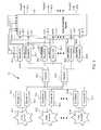
- FIG. 2is a block diagram of one embodiment of a video transmission system, in accordance with the present invention.
- FIG. 3is a block diagram of the video transmission system of FIG. 2 having a plurality of video sources.
- FIG. 4is a block diagram of one embodiment of a video protection switch that can be used in the video transmission systems of FIGS. 2 and 3 .
- the present inventionrelates generally to a system and method for providing redundant back-up to a video transmission system, and more particularly to a video changeover switch that can switch a video signal from primary equipment to back-up equipment upon the failure of the primary equipment.
- FIG. 2illustrates one embodiment of a video transmission system 5 in accordance with the present invention.
- video transmission system 5comprises a video source 10 , a first transmission path 12 - 1 and a second transmission path 12 - 2 through which the video signals from video source 10 pass, and remote from the video source 10 , a video protection switch (VPS) 30 for switching between the video signals passed over the two transmission paths.
- VPSvideo protection switch
- Video source 10can be any video signal producing device, such as a video camera, a VCR, a DVD player, the Internet, a cable system, or the like.
- a networkmay have several TV cameras covering the game, but only one signal typically is broadcast to the viewers at a time.
- the networkmay use computers to generate instant replays, statistical views, player profiles, etc.
- All of the signals from the various cameras, computers and other devices covering the gametypically are transmitted to an editing location for signal editing, switching and/or mixing. This allows the network to produce and transmit the best footage possible for the TV broadcast.
- first transmission path 12 - 1comprises a first encoder 15 , a first transmission channel 20 - 1 and a first decoder 25
- second transmission path 12 - 2comprises a second encoder 16 , a second transmission channel 20 - 2 and a second decoder 26 .
- encoders 15 , 16can be any device that transforms the video signal from video source 10 into a signal that can be easily transmitted over a communication or transmission path.
- encoders 15 , 16may convert the video signals into a compressed digital format, such as MPEG, MPEG2, or the like.
- decoders 25 , 26typically are devices that convert the transmission signal back into a video signal.
- encoders 15 , 16 and decoders 25 , 26may comprise, for example, Digilink 1220 encoders/decoders from Artel Video Systems, Inc., Marlborough, Mass.
- transmission channels 20may comprise any suitable communication channel.
- transmission channels 20comprise high bandwidth fiber optic cable.
- an optical multiplexeralso may be used to place more than one signal on each fiber channel, such as, for example, the MegaWav optical multiplexer from Artel Video Systems, Inc.
- VPS 30receives video signals 40 and 41 from the two transmission paths 12 - 1 and 12 - 2 , respectively, and produces a video output signal 45 from one of the two input video signals 40 or 41 .
- VPS 30receives alarm signals from alarm relay outputs 35 and 36 at decoders 25 and 26 , respectively.
- Alarm relay output 35sends an alarm signal to VPS 30 upon a detection of a video signal error or failure in transmission path 12 - 1 (e.g., errors introduced by encoder 15 , transmission channel 20 - 1 , or decoder 25 ), and alarm relay output 36 sends an alarm signal to VPS 30 upon a detection of a video signal error or failure in transmission path 12 - 2 .
- VPS 30switches from the failing transmission path to the back-up or other transmission path.
- FIG. 3illustrates a video transmission system 13 having a plurality of video sources 10 , each of which transmits video signals over two transmission paths in a manner similar to that in transmission system 5 in FIG. 2 .
- the first transmission path for the video signal from video source 10 - 1is first encoder 15 - 1 , first transmission channel 20 - 1 and first decoder 25 - 1
- the second transmission pathis second encoder 16 - 1 , second transmission channel 20 - 2 and second decoder 26 - 1 .
- the first transmission pathis first encoder 15 -N, first transmission channel 20 - 1 and first decoder 25 -N
- the second transmission pathis second encoder 16 -N, second transmission channel 20 - 2 and second decoder 26 -N.
- VPS 30generates a video output signal 45 from one of the video inputs 40 , 41 into VPS 30 originating from each of the transmission paths.
- output signal 45 - 1 from VPS 30is either video signal 40 - 1 originating from video source 10 - 1 and communicating through the first transmission path (encoder 15 - 1 , transmission channel 20 - 1 , and decoder 25 - 1 ) or video signal 41 - 1 communicating through the second transmission path (encoder 16 - 1 , transmission channel 20 - 2 , and decoder 26 - 1 ), depending on which path the VPS 30 is using.
- output signal 45 -N from VPS 30is either video signal 40 -N originating from video source 10 -N and passing through the first transmission path (encoder 15 -N, transmission channel 20 - 1 , and decoder 25 -N) or video signal 41 -N passing through the second transmission path (encoder 16 -N, transmission channel 20 - 2 , and decoder 26 -N).
- VPS 30receives input signals from two transmission paths for each video source 10 . That is, VPS 30 receives a first input signal 40 - 1 from the first transmission path for video source 10 - 1 , and a second input signal 41 - 1 from the second transmission path for video source 10 - 1 . Similarly, VPS 30 receives a first input signal 40 - 2 from the first transmission path for video source 10 - 2 , and a second input signal 41 - 2 from the second transmission path for video source 10 - 2 (and so on).
- VPS 30receives alarm signals from alarm relay outputs 35 and 36 from each of decoders 25 and 26 , respectively.
- the alarm signalsare provided to alarm controls 55 of switches 60 within VPS 30 , which in turn control which switch input 65 or 66 is connected to the outputs 45 .
- VPS 30can be pre-set so that the first input 65 - 1 is initially connected to output 1 45 - 1 by way of the switch 60 - 1 , and thus alarm control 55 - 1 is under the control of first alarm relay output 35 - 1 from decoder 25 - 1 .
- decoder 25 - 1will send an alarm signal to the VPS 30 by way of alarm relay output 35 - 1 .
- the alarm signalcauses alarm control 55 - 1 to change the state of switch 60 - 1 to connect output 45 - 1 to receive the signal from the second input 66 - 1 , and switch 60 - 1 stays in this state (i.e., input 66 - 1 provided to output 45 - 1 ) until reset.
- the other switches 60operate in the same way, each connecting switch input 65 to the output 45 unless an alarm signal is received at one of the alarm relay outputs 35 .
- the VPS 30is illustrated in operation after an alarm signal has been received from decoder 25 - 2 , indicating an error in the video signal from video service 10 - 2 (an error in the first transmission path-encoder 15 - 2 , channel 20 - 1 , and decoder 25 - 2 ).
- switch 60 - 1remains in the first state (input 65 connected to the out 45 - 1 ), but switch 60 - 2 has received an alarm signal (from alarm relay output 35 - 2 ) and has switched to the second state (input 66 - 2 connected to output 45 - 2 ).
- each switch 60is pre-set to connect input 65 to output 45 . If an alarm signal is present on any one of the alarm relay outputs 35 , the alarm control 55 for the corresponding switch changes to connect input signal 66 to the output 45 , and that connection continues until the switch is manually reset to the original position (i.e., connecting input signal 65 to the output 45 ).
- the alarm relay outputs 36may be actively used, and when any switch 60 changes to the second state (input 66 connected to output 45 by virtue of an alarm signal on alarm relay output 35 ), the switch stays in that state until an alarm signal is provided at the corresponding alarm relay output 36 . When that alarm signal from alarm relay output 36 is provided to the alarm control 55 , the switch is automatically changed back to the first state (input 65 connected to the output 45 ), without the need for a manual reset.
- the present inventionprovides means for overcoming a problem with a signal, while disrupting the transmission only momentarily, i.e. the brief switching time during which the alarm control 55 changes the one of the inputs 65 or 66 that is provided to output 45 .
- the present inventionprovides a video protection switch that continues to function after power loss.
- the VPS 30may also be provided with protection ports 70 - 1 , 70 - 2 according to one preferred embodiment of the present invention seen in FIG. 4 .
- the ports 70 - 1 , 70 - 2provide access to an extra or redundant switch 60 -P for connecting one of the inputs 40 , 41 to an output 45 , in the event one of the switches 60 fails or is otherwise inoperable.
- the inputs 40 , 41 corresponding to that output 45may be physically switched to protection port 70 - 1 and protection port 70 - 2 , respectively.
- output 45 - 2is not outputting the correct signal due to a failure of switch 60 - 2
- inputs 40 - 2 , 41 - 2may be physically disconnected from input 65 - 2 and input 66 - 2 , respectively.
- the video signal inputs 40 - 2 and 41 - 2may then be physically connected to protection port 1 70 - 1 and protection port 70 - 2 , respectively.
- first alarm relay output 35 - 2 and second alarm relay output 36 - 2(if used) are connected to alarm control 55 -P of switch 60 -P. Once connected, output 45 -P will provide the signals from either the first input 40 - 2 or the second input 41 - 2 , depending on the state of switch 60 -P.
- more redundancymay be provided by having more than two encoders and decoders per video source, the amount of channels being equal to the number of encoders and decoder per video source.
- the VPS 30could be modified to allow for more inputs per output to increase to the redundancy of the system.
- three encoders and decoders per video sourcemay be provided with three channels to carry the signals.
- the VPS 30would be modified to have three inputs per output and to receive three alarm relay outputs from the decoders.
- VPS 30can provide an external reset switch for each switch 60 individually (or all switches 60 , collectively) so that the switches 60 may be reset manually at any time (reset to their original, pre-set state).
- the present inventionprovides novel systems and methods for providing redundant back-up of a video transmission system. While detailed descriptions of one or more embodiments of the invention have been given above, various alternatives, modifications, and equivalents will be apparent to those skilled in the art without varying from the spirit of the invention. Therefore, the above description should not be taken as limiting the scope of the invention, which is defined by the appended claims.
Landscapes
- Engineering & Computer Science (AREA)
- Multimedia (AREA)
- Signal Processing (AREA)
- Computer Networks & Wireless Communication (AREA)
- Databases & Information Systems (AREA)
- Two-Way Televisions, Distribution Of Moving Picture Or The Like (AREA)
Abstract
Description
Claims (16)
Priority Applications (1)
| Application Number | Priority Date | Filing Date | Title |
|---|---|---|---|
| US13/936,006US8806563B2 (en) | 2002-02-22 | 2013-07-05 | Systems and methods for video transmission |
Applications Claiming Priority (3)
| Application Number | Priority Date | Filing Date | Title |
|---|---|---|---|
| US35903302P | 2002-02-22 | 2002-02-22 | |
| US10/146,522US8505063B2 (en) | 2002-02-22 | 2002-05-14 | Systems and methods for providing redundant back-up to a video transmission system |
| US13/936,006US8806563B2 (en) | 2002-02-22 | 2013-07-05 | Systems and methods for video transmission |
Related Parent Applications (1)
| Application Number | Title | Priority Date | Filing Date |
|---|---|---|---|
| US10/146,522ContinuationUS8505063B2 (en) | 2002-02-22 | 2002-05-14 | Systems and methods for providing redundant back-up to a video transmission system |
Publications (2)
| Publication Number | Publication Date |
|---|---|
| US20130293784A1 US20130293784A1 (en) | 2013-11-07 |
| US8806563B2true US8806563B2 (en) | 2014-08-12 |
Family
ID=27760040
Family Applications (2)
| Application Number | Title | Priority Date | Filing Date |
|---|---|---|---|
| US10/146,522Active2030-01-01US8505063B2 (en) | 2002-02-22 | 2002-05-14 | Systems and methods for providing redundant back-up to a video transmission system |
| US13/936,006Expired - LifetimeUS8806563B2 (en) | 2002-02-22 | 2013-07-05 | Systems and methods for video transmission |
Family Applications Before (1)
| Application Number | Title | Priority Date | Filing Date |
|---|---|---|---|
| US10/146,522Active2030-01-01US8505063B2 (en) | 2002-02-22 | 2002-05-14 | Systems and methods for providing redundant back-up to a video transmission system |
Country Status (1)
| Country | Link |
|---|---|
| US (2) | US8505063B2 (en) |
Cited By (4)
| Publication number | Priority date | Publication date | Assignee | Title |
|---|---|---|---|---|
| US10021433B1 (en)* | 2015-10-16 | 2018-07-10 | Tribune Broadcasting Company, Llc | Video-production system with social-media features |
| US20190313163A1 (en)* | 2018-04-05 | 2019-10-10 | Tvu Networks Corporation | Remote cloud-based video production system in an environment where there is network delay |
| US11212431B2 (en) | 2018-04-06 | 2021-12-28 | Tvu Networks Corporation | Methods and apparatus for remotely controlling a camera in an environment with communication latency |
| US11463747B2 (en) | 2018-04-05 | 2022-10-04 | Tvu Networks Corporation | Systems and methods for real time control of a remote video production with multiple streams |
Families Citing this family (18)
| Publication number | Priority date | Publication date | Assignee | Title |
|---|---|---|---|---|
| US8505063B2 (en) | 2002-02-22 | 2013-08-06 | Qwest Communications International Inc. | Systems and methods for providing redundant back-up to a video transmission system |
| KR100537305B1 (en)* | 2003-03-20 | 2005-12-16 | 원태영 | Video comperssion method for network digital video recorder |
| US20050097620A1 (en)* | 2003-10-30 | 2005-05-05 | Honeywell International Inc. | Architecture for multi-channel video processing |
| US8087058B2 (en) | 2004-01-19 | 2011-12-27 | Comcast Cable Holdings, Llc | HDTV subscriber verification |
| US20070230902A1 (en)* | 2006-03-31 | 2007-10-04 | Masstech Group Inc. | Dynamic disaster recovery |
| GB2468500B (en)* | 2009-03-11 | 2011-02-02 | Howard Thomas | A method and system for protecting multimedia equipment |
| US9197934B2 (en)* | 2012-05-17 | 2015-11-24 | Stmicroelectronics, Inc. | Fault tolerant system with equivalence processing driving fault detection and backup activation |
| EP2720470B1 (en)* | 2012-10-12 | 2018-01-17 | Sling Media, Inc. | Aggregated control and presentation of media content from multiple sources |
| TWI562673B (en)* | 2014-04-02 | 2016-12-11 | Hon Hai Prec Ind Co Ltd | Light circuit and electronic device |
| US9417921B2 (en) | 2014-07-31 | 2016-08-16 | Istreamplanet Co. | Method and system for a graph based video streaming platform |
| US9826011B2 (en) | 2014-07-31 | 2017-11-21 | Istreamplanet Co. | Method and system for coordinating stream processing at a video streaming platform |
| US9912707B2 (en)* | 2014-07-31 | 2018-03-06 | Istreamplanet Co. | Method and system for ensuring reliability of unicast video streaming at a video streaming platform |
| US9407944B1 (en) | 2015-05-08 | 2016-08-02 | Istreamplanet Co. | Resource allocation optimization for cloud-based video processing |
| US9686576B2 (en) | 2015-05-08 | 2017-06-20 | Istreamplanet Co. | Coordination of video stream timing in cloud-based video streaming system |
| US9344751B1 (en) | 2015-05-08 | 2016-05-17 | Istreamplanet Co. | Coordination of fault-tolerant video stream processing in cloud-based video streaming system |
| US10164853B2 (en) | 2015-05-29 | 2018-12-25 | Istreamplanet Co., Llc | Real-time anomaly mitigation in a cloud-based video streaming system |
| CN105959596A (en)* | 2016-05-24 | 2016-09-21 | 深圳市华泰敏信息技术有限公司 | Backup method and device of video source |
| CN111866405A (en)* | 2020-07-08 | 2020-10-30 | 华东计算技术研究所(中国电子科技集团公司第三十二研究所) | A Video Matrix Device Based on Optical Fiber Transmission |
Citations (9)
| Publication number | Priority date | Publication date | Assignee | Title |
|---|---|---|---|---|
| US4404589A (en) | 1980-10-21 | 1983-09-13 | Iri, Inc. | Cable television with multi-event signal substitution |
| US4748684A (en) | 1986-06-03 | 1988-05-31 | Information Resources, Inc. | Fast tuning control for a television system |
| US5485465A (en) | 1992-05-20 | 1996-01-16 | The Whitaker Corporation | Redundancy control for a broadcast data transmission system |
| US5600368A (en) | 1994-11-09 | 1997-02-04 | Microsoft Corporation | Interactive television system and method for viewer control of multiple camera viewpoints in broadcast programming |
| US6067346A (en) | 1998-12-18 | 2000-05-23 | Lucent Technologies Inc. | Method and system for providing redundancy in security systems served by a public switched telephone network |
| US6357028B1 (en) | 1999-03-19 | 2002-03-12 | Picturetel Corporation | Error correction and concealment during data transmission |
| US6487721B1 (en) | 1998-01-30 | 2002-11-26 | General Instrument Corporation | Apparatus and method for digital advertisement insertion in a bitstream |
| US20030163829A1 (en) | 2002-02-22 | 2003-08-28 | Qwest Communications International Inc. | Systems and methods for providing redundant back-up to a video transmission system |
| US7079176B1 (en) | 1991-11-25 | 2006-07-18 | Actv, Inc. | Digital interactive system for providing full interactivity with live programming events |
Family Cites Families (8)
| Publication number | Priority date | Publication date | Assignee | Title |
|---|---|---|---|---|
| US5581443A (en)* | 1994-09-14 | 1996-12-03 | Kabushiki Kaisha Toshiba | Structure for cooling a circuit module having a circuit board and a heat-generating IC chip mounted on the board, and portable electronic apparatus incorporating the structure |
| US5582240A (en)* | 1994-09-19 | 1996-12-10 | Motorola, Inc. | Pneumatically coupled heat sink assembly |
| US5694294A (en)* | 1995-01-27 | 1997-12-02 | Hitachi, Ltd. | Portable computer with fan moving air from a first space created between a keyboard and a first circuit board and a second space created between the first circuit board and a second circuit board |
| JP3258198B2 (en)* | 1995-04-28 | 2002-02-18 | 株式会社東芝 | Cooling device for circuit module and portable electronic device having this cooling device |
| JP3552559B2 (en)* | 1998-03-11 | 2004-08-11 | 株式会社デンソー | Heating element cooling device |
| US6577502B1 (en)* | 2000-06-28 | 2003-06-10 | Intel Corporation | Mobile computer having a housing with openings for cooling |
| US6418020B1 (en)* | 2001-03-30 | 2002-07-09 | Advanced Thermal Technologies | Heat dissipation device with ribbed fin plates |
| US6373700B1 (en)* | 2001-06-18 | 2002-04-16 | Inventec Corporation | Heat sink modular structure inside an electronic product |
- 2002
- 2002-05-14USUS10/146,522patent/US8505063B2/enactiveActive
- 2013
- 2013-07-05USUS13/936,006patent/US8806563B2/ennot_activeExpired - Lifetime
Patent Citations (10)
| Publication number | Priority date | Publication date | Assignee | Title |
|---|---|---|---|---|
| US4404589A (en) | 1980-10-21 | 1983-09-13 | Iri, Inc. | Cable television with multi-event signal substitution |
| US4748684A (en) | 1986-06-03 | 1988-05-31 | Information Resources, Inc. | Fast tuning control for a television system |
| US7079176B1 (en) | 1991-11-25 | 2006-07-18 | Actv, Inc. | Digital interactive system for providing full interactivity with live programming events |
| US5485465A (en) | 1992-05-20 | 1996-01-16 | The Whitaker Corporation | Redundancy control for a broadcast data transmission system |
| US5600368A (en) | 1994-11-09 | 1997-02-04 | Microsoft Corporation | Interactive television system and method for viewer control of multiple camera viewpoints in broadcast programming |
| US6487721B1 (en) | 1998-01-30 | 2002-11-26 | General Instrument Corporation | Apparatus and method for digital advertisement insertion in a bitstream |
| US6067346A (en) | 1998-12-18 | 2000-05-23 | Lucent Technologies Inc. | Method and system for providing redundancy in security systems served by a public switched telephone network |
| US6357028B1 (en) | 1999-03-19 | 2002-03-12 | Picturetel Corporation | Error correction and concealment during data transmission |
| US20030163829A1 (en) | 2002-02-22 | 2003-08-28 | Qwest Communications International Inc. | Systems and methods for providing redundant back-up to a video transmission system |
| US8505063B2 (en) | 2002-02-22 | 2013-08-06 | Qwest Communications International Inc. | Systems and methods for providing redundant back-up to a video transmission system |
Non-Patent Citations (13)
| Title |
|---|
| U.S. Appl. No. 10/146,522 l; Decision on Appeal dated Mar. 14, 2013; 8 pages. |
| U.S. Appl. No. 10/146,522; Advisory Action dated Nov. 14, 2008; 2 pages. |
| U.S. Appl. No. 10/146,522; Advisory Action dated Nov. 18, 2009; 2 pages. |
| U.S. Appl. No. 10/146,522; Advisory Action dated Nov. 24, 2008; 4 pages. |
| U.S. Appl. No. 10/146,522; Advisory Action dated Nov. 5, 2007; 4 pages. |
| U.S. Appl. No. 10/146,522; Final Rejection dated Aug. 20, 2007; 13 pages. |
| U.S. Appl. No. 10/146,522; Final Rejection dated Aug. 20, 2008; 12 pages. |
| U.S. Appl. No. 10/146,522; Final Rejection dated Sep. 1, 2009; 9 pages. |
| U.S. Appl. No. 10/146,522; Issue Notification dated Jul. 17, 2013; 1 page. |
| U.S. Appl. No. 10/146,522; Non-Final Rejection dated Feb. 27, 2009; 8 pages. |
| U.S. Appl. No. 10/146,522; Non-Final Rejection dated Feb. 4, 2008; 8 pages. |
| U.S. Appl. No. 10/146,522; Non-Final Rejection dated Mar. 16, 2007; 12 pages. |
| U.S. Appl. No. 10/146,522; Notice of Allowance dated Apr. 8, 2013; 17 pages. |
Cited By (6)
| Publication number | Priority date | Publication date | Assignee | Title |
|---|---|---|---|---|
| US10021433B1 (en)* | 2015-10-16 | 2018-07-10 | Tribune Broadcasting Company, Llc | Video-production system with social-media features |
| US20190313163A1 (en)* | 2018-04-05 | 2019-10-10 | Tvu Networks Corporation | Remote cloud-based video production system in an environment where there is network delay |
| US10966001B2 (en)* | 2018-04-05 | 2021-03-30 | Tvu Networks Corporation | Remote cloud-based video production system in an environment where there is network delay |
| US11317173B2 (en)* | 2018-04-05 | 2022-04-26 | Tvu Networks Corporation | Remote cloud-based video production system in an environment where there is network delay |
| US11463747B2 (en) | 2018-04-05 | 2022-10-04 | Tvu Networks Corporation | Systems and methods for real time control of a remote video production with multiple streams |
| US11212431B2 (en) | 2018-04-06 | 2021-12-28 | Tvu Networks Corporation | Methods and apparatus for remotely controlling a camera in an environment with communication latency |
Also Published As
| Publication number | Publication date |
|---|---|
| US20130293784A1 (en) | 2013-11-07 |
| US20030163829A1 (en) | 2003-08-28 |
| US8505063B2 (en) | 2013-08-06 |
Similar Documents
| Publication | Publication Date | Title |
|---|---|---|
| US8806563B2 (en) | Systems and methods for video transmission | |
| US7526001B2 (en) | Statistical multiplexer having protective features from extraneous messages generated by redundant system elements | |
| US8165060B2 (en) | Method and system for monitoring and switching between primary and back-up uplink signal processing circuits in a satellite communication system | |
| US8804499B2 (en) | Method and system for monitoring and switching between a first uplink signal processing circuit and a secondary uplink signal processing circuit | |
| US6986153B1 (en) | Apparatus and method for insertion of material in broadcasting | |
| US8792336B2 (en) | Method and system for monitoring and switching between primary and back-up receiver decoder circuits in a communication system | |
| US8424044B2 (en) | Method and system for monitoring and switching between a primary encoder and a back-up encoder in a communication system | |
| US20050086706A1 (en) | Television system | |
| US5479202A (en) | Television receiver for accessing switched broadband networks | |
| US20060053442A1 (en) | Apparatus and method for insertion of material in broadcasting | |
| US9055316B2 (en) | Method and system for inserting digital video effects into a video stream at a multiplexing device after routing | |
| US9461758B2 (en) | Method and system for monitoring various signals in a continuous processing circuit for a single channel in a communication system | |
| US7934228B2 (en) | Method and system for marking video signals for identification | |
| US20090068941A1 (en) | Method and System for Monitoring and Displaying Signals Corresponding to a Transponder of a Satellite in a Satellite Communication System | |
| US8239913B2 (en) | Method and system for inserting digital video effects into a video stream in redundant paths before routing | |
| US20040255327A1 (en) | Media content distribution system and method | |
| US20080244663A1 (en) | Method and system for inserting digital video effects into a video stream using a bypass router | |
| US20080240258A1 (en) | Method and system for generating uplink signals from a ground segment | |
| US10349014B2 (en) | Method and system for monitoring and simultaneously displaying a plurality of signal channels in a communication system | |
| US20060263044A1 (en) | Method of providing time shift function in audio/video network and apparatus for the same | |
| US6385745B1 (en) | Phase independent receiver and/or decoder | |
| US9473751B2 (en) | Method and system for operating a monitoring system for a satellite communication system | |
| CN119728891A (en) | Second field high-availability encoding and decoding system for ultra-high definition digital performance | |
| KR20180012514A (en) | Tv remote control system for the forced broadcast | |
| US20080239163A1 (en) | Method and system for inserting digital video effects into a video stream after bypass routing and before encoding |
Legal Events
| Date | Code | Title | Description |
|---|---|---|---|
| AS | Assignment | Owner name:QWEST COMMUNICATIONS INTERNATIONAL INC., COLORADO Free format text:ASSIGNMENT OF ASSIGNORS INTEREST;ASSIGNORS:COUFAL, WILLIAM C.;ADAMS, RANDALL E.;ACKERMAN, KURT E.;SIGNING DATES FROM 20020408 TO 20020428;REEL/FRAME:031052/0755 | |
| STCF | Information on status: patent grant | Free format text:PATENTED CASE | |
| AS | Assignment | Owner name:BANK OF AMERICA, N.A., AS COLLATERAL AGENT, NORTH CAROLINA Free format text:SECURITY INTEREST;ASSIGNOR:QWEST COMMUNICATIONS INTERNATIONAL INC.;REEL/FRAME:044652/0829 Effective date:20171101 Owner name:BANK OF AMERICA, N.A., AS COLLATERAL AGENT, NORTH Free format text:SECURITY INTEREST;ASSIGNOR:QWEST COMMUNICATIONS INTERNATIONAL INC.;REEL/FRAME:044652/0829 Effective date:20171101 | |
| MAFP | Maintenance fee payment | Free format text:PAYMENT OF MAINTENANCE FEE, 4TH YEAR, LARGE ENTITY (ORIGINAL EVENT CODE: M1551) Year of fee payment:4 | |
| AS | Assignment | Owner name:WELLS FARGO BANK, NATIONAL ASSOCIATION, NEW YORK Free format text:NOTES SECURITY AGREEMENT;ASSIGNOR:QWEST COMMUNICATIONS INTERNATIONAL INC.;REEL/FRAME:051692/0646 Effective date:20200124 | |
| MAFP | Maintenance fee payment | Free format text:PAYMENT OF MAINTENANCE FEE, 8TH YEAR, LARGE ENTITY (ORIGINAL EVENT CODE: M1552); ENTITY STATUS OF PATENT OWNER: LARGE ENTITY Year of fee payment:8 | |
| AS | Assignment | Owner name:QWEST COMMUNICATIONS INTERNATIONAL INC., LOUISIANA Free format text:RELEASE BY SECURED PARTY;ASSIGNOR:COMPUTERSHARE TRUST COMPANY, N.A, AS SUCCESSOR TO WELLS FARGO BANK, NATIONAL ASSOCIATION, AS NOTES COLLATERAL AGENT;REEL/FRAME:066885/0917 Effective date:20240322 |