US8803380B2 - Electric machine module cooling system and method - Google Patents
Electric machine module cooling system and methodDownload PDFInfo
- Publication number
- US8803380B2 US8803380B2US13/488,327US201213488327AUS8803380B2US 8803380 B2US8803380 B2US 8803380B2US 201213488327 AUS201213488327 AUS 201213488327AUS 8803380 B2US8803380 B2US 8803380B2
- Authority
- US
- United States
- Prior art keywords
- coolant
- electric machine
- channel
- housing
- sump
- Prior art date
- Legal status (The legal status is an assumption and is not a legal conclusion. Google has not performed a legal analysis and makes no representation as to the accuracy of the status listed.)
- Active, expires
Links
Images


Classifications
- H—ELECTRICITY
- H02—GENERATION; CONVERSION OR DISTRIBUTION OF ELECTRIC POWER
- H02K—DYNAMO-ELECTRIC MACHINES
- H02K9/00—Arrangements for cooling or ventilating
- H02K9/19—Arrangements for cooling or ventilating for machines with closed casing and closed-circuit cooling using a liquid cooling medium, e.g. oil
- H—ELECTRICITY
- H02—GENERATION; CONVERSION OR DISTRIBUTION OF ELECTRIC POWER
- H02K—DYNAMO-ELECTRIC MACHINES
- H02K5/00—Casings; Enclosures; Supports
- H02K5/04—Casings or enclosures characterised by the shape, form or construction thereof
- H02K5/20—Casings or enclosures characterised by the shape, form or construction thereof with channels or ducts for flow of cooling medium
- H02K5/203—Casings or enclosures characterised by the shape, form or construction thereof with channels or ducts for flow of cooling medium specially adapted for liquids, e.g. cooling jackets
- Y—GENERAL TAGGING OF NEW TECHNOLOGICAL DEVELOPMENTS; GENERAL TAGGING OF CROSS-SECTIONAL TECHNOLOGIES SPANNING OVER SEVERAL SECTIONS OF THE IPC; TECHNICAL SUBJECTS COVERED BY FORMER USPC CROSS-REFERENCE ART COLLECTIONS [XRACs] AND DIGESTS
- Y10—TECHNICAL SUBJECTS COVERED BY FORMER USPC
- Y10T—TECHNICAL SUBJECTS COVERED BY FORMER US CLASSIFICATION
- Y10T29/00—Metal working
- Y10T29/49—Method of mechanical manufacture
- Y10T29/4935—Heat exchanger or boiler making
Definitions
- Electric machinesoften contained within a machine cavity of a housing, generally include a stator and a rotor.
- the statorcan be secured to the housing different coupling techniques to generally secure the electric machine within the housing.
- heat energycan by generated by both the stator and the rotor, as well as other components of the electric machine.
- the increase in heat energycan, at least partially, impact electric machine operations.
- the modulecan include a housing, which can define a machine cavity.
- the housingcan include at least a portion of a coolant jacket, which can be configured to contain a first coolant.
- a coolant sumpcan be in fluid communication with the machine cavity and can be capable of containing a second coolant that is different from the first coolant.
- the coolant sumpcan be in thermal communication with the coolant jacket.
- an electric machinecan be positioned within the machine cavity and can be at least partially enclosed by the housing.
- the electric machinecan include a stator assembly, a rotor assembly that can be at least partially circumscribed by a portion of the stator assembly, and a shaft being that can be operatively coupled to the rotor assembly.
- an air gapcan be defined between a portion of the stator assembly and a portion of the rotor assembly.
- the coolant sumpcan positioned so that no material amounts of the second coolant can enter the air gap.
- FIG. 1is an isometric view of an electric machine module according to one embodiment of the invention.
- FIG. 2is a cross-sectional view of a portion of an electric machine module according to one embodiment of the invention.
- FIG. 3is a perspective view of a stator assembly according to one embodiment of the invention.
- FIG. 4is front view of a stator lamination according to one embodiment of the invention.
- FIG. 5is a perspective view of a conductor according to one embodiment of the invention.
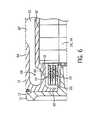
- FIG. 6is a partial cross-sectional view of a portion of an electric machine module according to one embodiment of the invention.
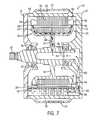
- FIG. 7is a cross-sectional view of an electric machine module according to one embodiment of the invention.
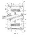
- FIG. 8is a cross-sectional view of an electric machine module according to one embodiment of the invention.
- FIG. 9is a perspective view of a rotor assembly according to one embodiment of the invention.
- FIG. 10is a cross-sectional view of an electric machine module according to one embodiment of the invention.
- FIG. 11is a side view of an electric machine module according to one embodiment of the invention.
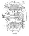
- FIG. 12is a cross-sectional view of an electric machine module according to one embodiment of the invention.
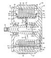
- FIGS. 1 and 2illustrate an electric machine module 10 according to one embodiment of the invention.
- the module 10can include a housing 12 comprising a sleeve member 14 , a first end cap 16 , and a second end cap 18 .
- An electric machine 20can be housed within a machine cavity 22 at least partially defined by the sleeve member 14 and the end caps 16 , 18 .
- the sleeve member 14 and the end caps 16 , 18can be coupled via conventional fasteners 17 , or another suitable coupling method, to enclose at least a portion of the electric machine 20 within the machine cavity 22 .
- the housing 12can comprise a substantially cylindrical canister 15 coupled to a single end cap 19 .
- the housing 12can comprise materials that can generally include thermally conductive properties, such as, but not limited to aluminum or other metals and materials capable of generally withstanding operating temperatures of the electric machine.
- the housing 12can be fabricated using different methods including casting, molding, extruding, and other similar manufacturing methods.
- the electric machine 20can include a rotor assembly 24 , a stator assembly 26 , including stator end turns 28 , and bearings 30 , and can be disposed about a shaft 35 .
- the stator assembly 26can substantially circumscribe at least a portion of the rotor assembly 24 .
- the rotor assembly 24can also include a rotor hub 32 or can have a “hub-less” design (not shown).
- the electric machine 20can comprise a substantially conventional configuration.
- an air gap 25can be defined between a portion of the stator assembly 26 and a portion of the rotor assembly 24 .
- the electric machine 20can be operatively coupled to the module housing 12 .
- the electric machine 20can be fit within the housing 12 .
- the electric machine 20can be fit within the housing 12 using an interference fit, a shrink fit, other similar friction-based fit that can at least partially operatively couple the machine 20 and the housing 12 .
- the stator assembly 26can be shrunk fit into the module housing 12 . Further, in some embodiments, the fit can at least partially secure the stator assembly 26 , and as a result, the electric machine 20 , in both axial and circumferential directions.
- the fit between the stator assembly 26 and the module housing 12can at least partially serve to transfer torque from the stator assembly 26 to the module housing 12 . In some embodiments, the fit can result in a generally greater amount of torque retained by the module 10 .
- the electric machine 20can be, without limitation, an electric motor, such as a hybrid electric motor, an electric generator, or a vehicle alternator.
- the electric machine 20can be a High Voltage Hairpin (HVH) electric motor or an interior permanent magnet electric motor for hybrid vehicle applications.
- HVHHigh Voltage Hairpin
- Components of the electric machine 20such as, but not limited to, the rotor assembly 24 , the stator assembly 26 , and the stator end turns 28 can generate heat during operation of the electric machine 20 . These components can be cooled to increase the performance and the lifespan of the electric machine 20 .
- the stator assembly 26can comprise a stator core 34 and a stator winding 36 at least partially disposed within a portion of the stator core 34 .
- the stator core 34can comprise a plurality of laminations 38 .
- the laminations 38can comprise a plurality of substantially radially-oriented teeth 40 .
- the teeth 40can substantially align to define a plurality of slots 42 that are configured and arranged to support at least a portion of the stator winding 36 . As shown in FIG.
- the laminations 38can include sixty teeth 40 , and, as a result, the stator core 28 can include sixty slots 42 .
- the laminations 38can include more or fewer teeth 40 , and, accordingly, the stator core 34 can include more or fewer slots 42 .
- the stator core 34can comprise an inner perimeter 41 and an outer perimeter 43 .
- the stator core 34can comprise a substantially cylindrical configuration so that the inner and outer perimeters 41 , 43 can comprise inner and outer diameters, respectively.
- stator core 34can comprise other configurations (e.g., square, rectangular, elliptical, regular or irregular polygonal, etc.), and, as a result, the inner and outer perimeters 41 , 43 can comprise other dimensions.
- the stator winding 36can comprise a plurality of conductors 44 .
- the conductors 44can comprise a substantially segmented configuration (e.g., a hairpin configuration), as shown in FIGS. 3 and 5 .
- at least a portion of the conductors 44can include a turn portion 46 and at least two leg portions 48 .
- the turn portion 46can be disposed between the two leg portions 48 to connect the two leg portions 48 , which can be substantially parallel.
- the turn portion 46can comprise a substantially “u-shaped” configuration, although, in some embodiments, the turn portion 46 can comprise a v-shape, a wave shape, a curved shape, and other shapes.
- At least a portion of the conductors 44can comprise a substantially rectangular cross section. In some embodiments, at least a portion of the conductors 44 can comprise other cross-sectional shapes, such as substantially circular, square, hemispherical, regular or irregular polygonal, etc. In some embodiments, the conductors 44 can comprise other configurations (e.g., substantially non-segmented configuration).
- the conductors 44can be positioned substantially within the slots 42 .
- the stator core 34can be configured so that the plurality of slots 42 are substantially axially arranged.
- the leg portions 48can be inserted into the slots 42 so that at least some of the leg portions 48 can axially extend through the stator core 34 .
- the leg portions 48can be inserted into neighboring slots 42 .
- the leg portions 48 of a conductor 44can be disposed in slots that are distanced approximately one magnetic-pole pitch apart (e.g., six slots, eight slots, etc.).
- a plurality of conductors 44can be disposed in the stator core 34 so that at least some of the turn portions 46 of the conductors 44 axially extend from the stator core 34 at a first axial end 50 of the stator core 34 and at least some of the leg portions 48 axially extend from the stator core 34 at a second axial end 52 of the stator core 34 .
- at least a portion of the conductor 44 regions that axially extend from the core 34 at the axial ends 50 , 52can comprise the stator end turns 28 .
- the conductors 44can be generally fabricated from a substantially linear conductor 44 that can be configured and arranged to a shape substantially similar to the conductor in FIG. 5 .
- a machine(not shown) can apply a force (e.g., bend, push, pull, other otherwise actuate) to at least a portion of a conductor 44 to substantially form the turn portion 46 and the two leg portions 48 of a single conductor 44 .
- the leg portions 48can comprise multiple regions.
- the leg portions 48can comprise in-slot portions 54 , angled portions 56 , and connection portions 58 .
- the leg portions 48can be disposed in the slots 42 and can axially extend from the first end 50 to the second end 52 .
- at least a portion of the leg portions 48 positioned within the slots 42can comprise the in-slot portions 58 .
- the leg portions 48can be substantially radially aligned, as shown in FIG. 3 .
- the leg portions 48can comprise other configurations.
- stator end turns 28 extending from the stator core 34 at the second axial end 52can comprise the angled portions 56 and the connection portions 58 .
- the leg portions 48 extending from the stator core 34 at the second axial end 52can undergo a twisting process (not shown) that can lead to the formation of the angled portions 56 and the connection portions 58 .
- the twisting processcan give rise to the angled portions 56 at a more axially inward position and the connection portions 58 at a more axially outward position, as shown in FIGS. 3 and 5 .
- connection portions 58 of at least a portion of the conductors 44can be immediately adjacent to connection portions 58 of other conductors 44 .
- the connection portions 58can be coupled together to form one or more stator windings 36 .
- the connection portions 58can be coupled via welding, brazing, soldering, melting, adhesives, or other coupling methods.
- the angled portions 56 and the connection portions 58can extend from the first axial end 50 and can be configured and arranged in a similar manner as some previously mentioned embodiments.
- the housing 12can comprise at least a portion of a coolant jacket 60 .
- the housing 12can include an inner surface 62 and an outer surface 64 and the coolant jacket 60 can be positioned substantially between at least a portion the surfaces 62 , 64 .
- the coolant jacket 60can comprise an alternative configuration.
- the outer surface 64 of the housing 12can comprise a portion of the coolant jacket 60 and a coolant jacket member 67 can be coupled to the outer surface 64 to form the coolant jacket 60 .
- the coolant jacket member 67can comprise a portion of a separate housing (e.g., a transmission housing, an engine housing, etc.), which can be positioned adjacent to the outer surface 64 to define the coolant jacket 60 .
- the machine cavity 22can be at least partially defined by the inner surface 62 (e.g., each of the elements of the housing 12 can comprise a portion of the inner surface 62 ).
- the coolant jacket 60can substantially circumscribe at least a portion of the electric machine 20 .
- the coolant jacket 60can substantially circumscribe at least a portion of the outer perimeter 43 of the stator assembly 26 (e.g., the stator core 34 and the stator winding 36 ), including portions of the stator end turns 28 .
- the coolant jacket 60can contain a first coolant that can comprise transmission fluid, ethylene glycol, an ethylene glycol/water mixture, water, oil, motor oil, a gas, a mist, or another substance.
- the coolant jacket 60can be in fluid communication with a coolant source (not shown), which can pressurize the coolant prior to or as it is being dispersed into the coolant jacket 60 via one or more inlets 87 , so that the pressurized coolant can circulate through the coolant jacket 60 .
- the coolant jacket 60can be in thermal communication with some elements of the electric machine 20 (e.g., the stator assembly 26 ) so that at least a portion of the thermal energy generated by the electric machine 20 can be transferred to the first coolant (e.g., via conduction, convention, or any other energy-transfer method).
- the coolant jacket 60can substantially circumscribe a portion of the stator assembly 26 so that as the first coolant circulates through the coolant jacket 60 , the first coolant can receive a portion of the thermal energy rejected by the stator assembly 26 .
- the first coolantcan be directed to a heat transfer element (e.g., a radiator, a heat exchanger, etc.) (not shown), which can remove the heat energy from the first coolant and then the first coolant can be recirculated through the coolant jacket 60 for additional cooling.
- a heat transfer elemente.g., a radiator, a heat exchanger, etc.
- the inner surface 62can comprise one or more coolant apertures 66 so that the coolant jacket 60 can be in fluid communication with the machine cavity 22 , as shown in FIGS. 2 and 6 .
- the coolant apertures 66can be positioned substantially adjacent to the stator end turns 28 .
- the coolantcan contact the stator end turns 28 , which can lead to at least partial cooling.
- the coolantAfter exiting the coolant apertures 66 , at least a portion of the coolant can flow through the machine cavity 22 and can contact various module 10 elements, which, in some embodiments, can lead to at least partial cooling of the module 10 .
- the coolant jacket 60can be substantially or completely sealed relative to the machine cavity 22 .
- the first coolantcan pass through the coolant jacket 60 and no material amounts of the first coolant will enter the machine cavity 22 and contact the electric machine 20 .
- the coolant jacket 60can include multiple configurations.
- at least a portion of the coolant jacket 60can extend through portions of the housing 12 (e.g., the sleeve member 14 ) a distance substantially similar to an axial length of the stator assembly 26 .
- an axial length of a portion of the coolant jacket 60can extend at least the same distance as the axial length of the stator assembly 26 , including the stator end turns 28 .
- portions of the coolant jacket 60can extend greater and lesser axial distances, as desired by manufacturers and/or end users for cooling.
- a portion of the coolant jacket 60also can comprise at least one radial extension 68 .
- a region of the inner surface 62can be radially recessed so that the radial extension 68 of the coolant jacket 60 can be substantially adjacent to at least a portion of the stator end turns 28 .
- radial extensions 68can be positioned adjacent to one side of, both sides of, or neither sides of the stator end turns 28 .
- the coolant jacket 60can comprise radial extensions 68 substantially continuously adjacent to at least a portion of an outer diameter 70 of at least one set of the stator end turns 28 (i.e., one continuous radial extension 68 around at least a portion of a circumference of at least one set of the stator end turns 28 ).
- the coolant jacket 60can comprise substantially discrete radial extensions 68 positioned around at least a portion of the outer diameter 70 of at least one set of the stator end turns 28 .
- the housing 12can comprise at least two radial extensions 68 .
- the housing 12can comprise two halves coupled together in a substantially axially central location so that each half of the housing 12 can comprise a radial extension 68 and the electric machine 20 can be positioned substantially between the two halves.
- the radial extension 68can comprise a radial length substantially similar to other portions of the coolant jacket 60 .
- the stator end turns 28can comprise a generally lesser outer diameter 70 compared to the outer diameter 43 of the stator core 34 .
- a greater distancecan exist between the stator end turns 28 and the cooling jacket 60 in some conventional configurations because at least some conventional coolant jackets 60 comprise a generally linear and/or uniform configuration (e.g., some conventional coolant jackets 60 comprise a generally planar configuration).
- the radial extensions 68 of the coolant jacket 60can enhance module 10 cooling because some of the coolant can circulate relatively closer to the stator end turns 28 , compared to conventional coolant jacket 60 configurations that lack radial extensions 68 .
- a distance between the circulating coolant and an area rejecting thermal energye.g., the stator end turns 28
- an area rejecting thermal energye.g., the stator end turns 28
- the module 10can comprise at least one coolant sump 72 .
- the coolant sump 72can be in fluid communication with the machine cavity 22 .
- the coolant sump 72can be positioned at or near a bottom or lower portion of the machine cavity 22 .
- the coolant sump 72can be configured and arranged to contain a second coolant, such as oil, vaporizable dielectric fluid, an oil/vaporizable dielectric fluid mixture, or a similar substance.
- the second coolantcan include properties such as, but not limited to: a high dielectric constant, low electrical conductivity, high thermal conductivity, and an ability to lubricate module 10 components.
- a resting level of the second coolant present within the coolant sump 72can generally be located below the air gap 25 between the rotor and stator assemblies 24 , 26 .
- the second coolantcan cover and/or coat at least a portion of the stator end turns 28 positioned in the lower portion of the machine cavity 22 .
- the second coolant and the coolant sump 72can comprise a portion of a closed-loop cooling system.
- the module 10can remain substantially sealed so most of the second coolant remains within the machine cavity 22 and/or the coolant sump 72 , unless the housing 12 is disassembled.
- the coolant sump 72can comprise alternative configurations.
- the coolant sump 72can comprise structures coupled to and/or integral with some portions of the inner surface 62 of the housing 12 (i.e., structures extending axially and/or radially inward from the inner wall 62 of the housing 12 to define the coolant sump 72 ).
- the coolant sump 72can be a structure operatively coupled a bottom portion of the housing 12 and in fluid communication with the machine cavity 22 , as shown in FIG. 8 .
- the structurecan be substantially arcuate to substantially align with the bottom portion of the outer surface 64 of the housing 12 .
- the structurecan be substantially integral with a portion of the housing 12 .
- the coolant sump 72can comprise a separate reservoir remotely positioned relative to the housing 12 and in fluid communication with the machine cavity 22 .
- the second coolantcan be dispersed in different manners through at least a portion the machine cavity 22 .
- at least a portion of the second coolantcan be drawn from the coolant sump 72 in a generally upward direction by a pump or a structure which creates a pumping effect.
- the pump and/or the structure which creates a pumping effectcan comprise different forms.
- the rotor assembly 24can comprise one or more centrifugal fans 74 coupled to one or both axial ends of the rotor assembly 24 , as shown in FIG. 9 .
- the rotor assembly 24 and the centrifugal fans 74can be coupled together so that the centrifugal fans 74 can rotate synchronously with the rotor assembly 24 during electric machine 20 operations.
- the centrifugal fans 74can contact the second coolant disposed in the coolant sump 72 and can pull the second coolant from the coolant sump 72 and disperse or sling the second coolant through portions of the motor cavity 22 to contact portions of the housing 12 and the electric machine 20 (e.g., the stator end turns 28 ).
- the moving rotor assembly 24when the electric machine 20 is in operation, can create an area of localized low pressure substantially at or near the surface level of the second coolant in the coolant sump 72 (i.e., the Bernoulli Effect can draw least a portion of the second coolant toward the rotor assembly 24 ).
- the second coolantcontacts the rotor assembly 24 , the second coolant can be carried by the rotor assembly 24 and centrifugally dispersed in a substantially outward path through portions the machine cavity 22 , thus contacting at least the stator assembly 26 , the stator end turns 28 , and/or the bearings 30 .
- the pump or the structure which creates a pumping effectcan comprise any variety of conventional pump 76 or other similar structures that can disperse the second coolant.
- the pump 76can be operatively coupled to the housing 12 , rotor hub 32 , other portions of the rotor assembly 24 , and/or the shaft 35 , as shown in FIGS. 10 and 11 .
- the pump 76can be integrated into at least one portion the housing 12 , integrated into the rotor hub 32 , or it can be an integral portion of the electric machine 20 .
- the pump 76can comprise a conventional pump (e.g., an electric pump, a gear-type pump, a vane-type pump, a centrifugal pump, or other suitable conventional pumps) that can be coupled to the outer surface 64 (as shown in FIG. 10 ) or remotely located and in fluid communication with at least the machine cavity 22 and the coolant sump 72 .
- a conventional pumpe.g., an electric pump, a gear-type pump, a vane-type pump, a centrifugal pump, or other suitable conventional pumps
- the pump 76can comprise a conventional gerotor-type pump 76 , as shown in FIG. 11 .
- the gerotor-type pump 76can be operatively coupled to and/or integral with a portion of the shaft 35 so that the movement of the shaft 35 during operation of the machine 20 can drive operation of the pump 76 .
- the gerotor-style pump 76can comprise an inner rotor 78 and an outer rotor 80 .
- the inner rotor 78can be operatively coupled to the rotor hub 32 and/or the shaft 35 and the outer rotor 80 can be operatively coupled to at least one the end caps 16 , 18 , and 19 (e.g., either the inner surface 62 or the outer surface 64 ) or other locations proximal to the module 10 .
- the inner rotor 78can be operatively coupled to elements of the module 10 so that the inner rotor 78 is generally concentric with the rotor hub 32 and/or the shaft 35 and the outer rotor 80 is disposed generally radially outward relative to at least a portion of the inner rotor 78 .
- the rotor hub 32 and/or the shaft 35can move during operation of the electric machine 20 , which can lead to movement of the inner rotor 78 .
- the divergence of the inner rotor 78 and the outer rotor 80can create a suction force which draws the second coolant into the pump 76 , and the merging of the inner rotor 78 and the outer rotor 80 create pressure which forces the second coolant out of the pump 76 .
- the pump 76can aid in dispersing of the second coolant through the module 10 , as described in further detail below.
- the housing 12can include at least one coolant channel 82 .
- the coolant channel 82can be generally positioned between the inner surface 62 and the outer surface 64 .
- the coolant channel 82can be in fluid communication with the coolant sump 72 through a sump outlet 84 and can extend through at least a portion of the housing 12 , as shown in FIG. 7 .
- the sump outlet 84 and the coolant channel 82can be positioned at or substantially adjacent to one axial end of the coolant sump 72 and the housing 12 , respectively, as shown in FIG. 7 .
- the coolant channel 82can be in fluid communication with a shaft channel 86 .
- a portion of the shaft 35can comprise the shaft channel 86 positioned substantially within the shaft 35 and arranged in a generally axial orientation, as shown in FIG. 7 .
- the shaft channel 86can extend the entire axial length of the shaft 35 .
- the shaft channel 86can extend a length less than the axial length of the shaft 35 , as shown in FIG. 7 .
- a portion of the rotor assembly 24can include a rotor channel 88 .
- the rotor channel 88can extend some or all of the radial length of the rotor assembly 24 (i.e., from an inner diameter of the rotor assembly 24 to an outer diameter of the rotor assembly 24 ).
- the rotor channel 88can extend a length less than the radial length of the rotor assembly 24 .
- the rotor channel 88can be in fluid communication with the shaft channel 86 and the machine cavity 22 , as shown in FIG. 7 . For example, as shown in FIG.
- the rotor channel 88can divide into at least two rotor channels 88 , as shown in FIG. 7 .
- the rotor assembly 24can comprise one or more coolant outlets 90 that are in fluid communication with the rotor channels 88 .
- the coolant outlets 90can be configured and arranged so that a portion of the exiting second coolant can be directed toward the stator end turns 28 and other portions of the stator assembly 26 and the housing 12 for cooling, as shown by the arrows in FIG. 7 .
- the second coolantcan be dispersed within portions of the module 10 to aid in cooling and lubricating module 10 components.
- the pump 76can cause a portion of the second coolant to flow from the coolant sump 72 , through the sump outlet 84 and into the coolant channel 82 (e.g., the pump 76 can draw at least a portion of the second coolant in a generally radially inward direction).
- the pump 76can then direct at least a portion of the second coolant to flow through the shaft channel 86 and the rotor channel 88 and enter the machine cavity 22 via the coolant outlets 90 , where the second coolant can aid in cooling the module 10 components.
- the second coolantcan receive at least a portion of the thermal energy generated by the housing 12 , the shaft 35 , and the rotor assembly 24 , respectively.
- the second coolantcan provide cooling due to forced convection of thermal energy from the components to the second coolant. Additionally, the second coolant can provide added lubrication to the bearings 30 and other moving elements of the electric machine module 10 .
- the coolant sump 72 , the coolant channel 82 , the shaft channel 86 , the rotor channel 88 , and the second coolantcan increase thermal energy transfer from at least the stator end turns 28 , the rotor assembly 24 , and other portions of the electric machine 20 and can create a more effective way to sink thermal energy into the coolant jacket 60 .
- the second coolantcan receive thermal energy from portions of the electric machine 20 (e.g., the stator end turns 28 and the rotor assembly 24 ) through forced convection, as previously mentioned.
- both axial sides of the electric machine 12can be in fluid communication via a feature in the outer perimeter 43 of the stator core 34 and/or the inner surface 62 of the housing 14 .
- the featurecan comprise a recess positioned on the outer perimeter 43 and/or the inner surface so that the axial ends 50 , 52 of the stator assembly 24 can be in fluid communication with each other.
- the second coolant in the coolant sump 72can be maintained at a lower temperature because the heated second coolant can mix with the cooler, unused second coolant, which can reduce the overall temperature.
- the second coolantcan remove additional thermal energy from the electric machine 20 when it is recycled through the module 10 .
- the coolant sump 72can be located in the machine cavity 22 substantially adjacent to a portion of the coolant jacket 60 , as shown in FIG. 7 .
- the coolant sump 72can be in thermal communication with the coolant jacket 60 .
- the first coolantcan be directed out of the coolant jacket 60 to the heat transfer element, which can help remove the thermal energy from the operating electric machine 20 .
- the first coolantcan be circulated through a heat exchange system and the second coolant can remain within the housing 12 and/or the coolant sump 72 so that the second coolant does not have to pass through any other elements (e.g., a transmission housing), which can simplify installation and maintenance of the electric machine module 10 .
- the coolant jacket 60can be localized to a region of the housing 12 substantially adjacent to the coolant sump 72 , as shown in FIG. 12 .
- the coolant jacket 60can be configured so that it is located adjacent to the coolant sump 72 and does not substantially circumscribe other portions of the module 10 (i.e., the coolant jacket 60 serves as a heat exchange element for the coolant sump 72 ).
- the housing 12can be configured so that the coolant sump 72 can surround at least a portion of the coolant jacket 60 (not shown).
- the coolant sump 72can be generally external with machine cavity 22 , as shown in FIG. 8 , and the coolant jacket 60 can be positioned substantially internally with respect to the coolant sump 72 (i.e., the coolant sump 72 and the second coolant can substantially circumscribe and/or surround at least a portion of the coolant jacket 60 ).
- the coolant sump 72 and the second coolantcan substantially circumscribe and/or surround at least a portion of the coolant jacket 60 ).
- the coolant sump 72 and/or the coolant channels 82 , 86 , and 88 with the second coolantcan increase the continuous performance of, and reduce the operating temperature of the electric machine 20 , thus increasing both durability and efficiency of the electric machine 20 .
- use of the coolant sump 72 and/or the coolant channels 82 , 84 , and 86can the reduce the work required by the first coolant and the coolant jacket 60 to cool the electric machine 20 .
- a necessary flow rate of the first coolant in the coolant jacket 60can be reduced, which can increase efficiency of the electric machine module 10 (e.g., by reducing pumping losses to and from the fluid source), and an allowable coolant inlet temperature can be increased, which can reduce the required size of the heat transfer element or eliminate a need for the heat transfer element completely, thus reducing system costs of the electric machine module 10 .
Landscapes
- Engineering & Computer Science (AREA)
- Power Engineering (AREA)
- Motor Or Generator Cooling System (AREA)
Abstract
Description
Claims (15)
Priority Applications (1)
| Application Number | Priority Date | Filing Date | Title |
|---|---|---|---|
| US13/488,327US8803380B2 (en) | 2011-06-03 | 2012-06-04 | Electric machine module cooling system and method |
Applications Claiming Priority (2)
| Application Number | Priority Date | Filing Date | Title |
|---|---|---|---|
| US201161493310P | 2011-06-03 | 2011-06-03 | |
| US13/488,327US8803380B2 (en) | 2011-06-03 | 2012-06-04 | Electric machine module cooling system and method |
Publications (2)
| Publication Number | Publication Date |
|---|---|
| US20120305226A1 US20120305226A1 (en) | 2012-12-06 |
| US8803380B2true US8803380B2 (en) | 2014-08-12 |
Family
ID=47259967
Family Applications (1)
| Application Number | Title | Priority Date | Filing Date |
|---|---|---|---|
| US13/488,327Active2032-10-27US8803380B2 (en) | 2011-06-03 | 2012-06-04 | Electric machine module cooling system and method |
Country Status (2)
| Country | Link |
|---|---|
| US (1) | US8803380B2 (en) |
| WO (1) | WO2012167274A1 (en) |
Cited By (18)
| Publication number | Priority date | Publication date | Assignee | Title |
|---|---|---|---|---|
| US20110298315A1 (en)* | 2010-06-04 | 2011-12-08 | Remy Technologies, Llc | Electric Machine Cooling System and Method |
| US20130043747A1 (en)* | 2011-08-18 | 2013-02-21 | Larry A. Kubes | Electric Machine Cooling |
| US20160322876A1 (en)* | 2014-01-17 | 2016-11-03 | Mitsubishi Electric Corporation | Rotary electric machine |
| US10069375B2 (en)* | 2012-05-02 | 2018-09-04 | Borgwarner Inc. | Electric machine module cooling system and method |
| US20190006908A1 (en)* | 2017-06-30 | 2019-01-03 | Audi Ag | Electric machine and motor vehicle |
| USD852938S1 (en) | 2018-05-07 | 2019-07-02 | S. C. Johnson & Son, Inc. | Dispenser |
| USD853548S1 (en) | 2018-05-07 | 2019-07-09 | S. C. Johnson & Son, Inc. | Dispenser |
| US10358040B1 (en)* | 2015-06-01 | 2019-07-23 | Hydro-Gear Limited Partnership | Drive assembly and system for utility vehicle |
| USD872245S1 (en) | 2018-02-28 | 2020-01-07 | S. C. Johnson & Son, Inc. | Dispenser |
| USD872847S1 (en) | 2018-02-28 | 2020-01-14 | S. C. Johnson & Son, Inc. | Dispenser |
| USD878538S1 (en) | 2018-02-28 | 2020-03-17 | S. C. Johnson & Son, Inc. | Dispenser |
| USD881365S1 (en) | 2018-02-28 | 2020-04-14 | S. C. Johnson & Son, Inc. | Dispenser |
| US20220320922A1 (en)* | 2019-06-03 | 2022-10-06 | Valeo Equipements Electriques Moteur | Rotating electric machine provided with a cooling chamber |
| US20220337113A1 (en)* | 2021-04-20 | 2022-10-20 | Rivian Ip Holdings, Llc | Rotor assembly and method for motor end winding cooling and bearing lubrication |
| US20230038386A1 (en)* | 2019-12-10 | 2023-02-09 | Eaton Intelligent Power Limited | Axial flux motor with cooling jacket |
| DE102021121032A1 (en) | 2021-08-12 | 2023-02-16 | Bayerische Motoren Werke Aktiengesellschaft | Jacket sleeve for a stator cooling jacket |
| US12341378B2 (en) | 2019-11-06 | 2025-06-24 | Eaton Intelligent Power Limited | Axial flux motor with stator cores having enlarged face plates |
| US12424897B2 (en) | 2020-02-21 | 2025-09-23 | Eaton Intelligent Power Limited | Electric motor with integrated cooling system |
Families Citing this family (24)
| Publication number | Priority date | Publication date | Assignee | Title |
|---|---|---|---|---|
| EP2793375B1 (en)* | 2013-04-15 | 2018-03-28 | Visedo Oy | A stator for an electrical machine of a mobile working machine |
| JP6368492B2 (en) | 2014-01-20 | 2018-08-01 | 株式会社日立製作所 | Rotating electric machine |
| US20160020673A1 (en)* | 2014-07-18 | 2016-01-21 | Hamilton Sundstrand Corporation | Rotor cooling |
| US9762106B2 (en)* | 2014-12-04 | 2017-09-12 | Atieva, Inc. | Motor cooling system |
| US20160164378A1 (en)* | 2014-12-04 | 2016-06-09 | Atieva, Inc. | Motor Cooling System |
| KR101703595B1 (en)* | 2015-05-20 | 2017-02-07 | 현대자동차 주식회사 | Motor having cooling structure |
| WO2017203562A1 (en)* | 2016-05-23 | 2017-11-30 | 三菱電機株式会社 | Rotating electric machine |
| US11289980B2 (en)* | 2017-07-28 | 2022-03-29 | Nidec Corporation | Motor |
| JP7275432B2 (en)* | 2017-07-28 | 2023-05-18 | ニデック株式会社 | motor |
| CN111033972B (en)* | 2017-09-08 | 2022-02-22 | 日本电产株式会社 | Drive device |
| WO2019049465A1 (en)* | 2017-09-08 | 2019-03-14 | 日本電産株式会社 | Drive device |
| US10910916B2 (en)* | 2017-11-30 | 2021-02-02 | General Electric Company | Fluid cooled and fluid insulated electric machine |
| US11007862B2 (en)* | 2018-04-30 | 2021-05-18 | Schaeffler Technologies AG & Co. KG | Hybrid module including rotor adhesively bonded to rotor carrier |
| US11122715B2 (en)* | 2018-05-11 | 2021-09-14 | General Electric Company | Conformal heat pipe assemblies |
| EP3805030A4 (en)* | 2018-06-07 | 2021-08-04 | Yamaha Hatsudoki Kabushiki Kaisha | ELECTRIC VEHICLE AND DRIVE DEVICE FOR IT |
| US20210257878A1 (en)* | 2018-06-15 | 2021-08-19 | Lg Electronics Inc. | Electric motor |
| JP6650982B1 (en)* | 2018-09-26 | 2020-02-19 | 株式会社M−Tec | Rotating electric machine and its cooling system |
| JP7016784B2 (en) | 2018-10-19 | 2022-02-07 | 本田技研工業株式会社 | Rotating machine |
| CN111313611A (en)* | 2018-12-12 | 2020-06-19 | 晟昌机电股份有限公司 | Motor cooling structure |
| US11305883B2 (en) | 2019-03-01 | 2022-04-19 | United Technologies Advanced Projects, Inc. | Circulating coolant fluid in hybrid electrical propulsion systems |
| EP3730946B1 (en)* | 2019-04-23 | 2023-04-26 | Ningbo Geely Automobile Research & Development Co. Ltd. | Shaft arrangement for a vehicle |
| US11649064B2 (en) | 2019-08-02 | 2023-05-16 | Hamilton Sundstrand Corporation | Integrated motor drive cooling |
| US12030651B2 (en) | 2021-01-05 | 2024-07-09 | Pratt & Whitney Canada Corp. | Parallel hybrid power plant with hollow motor |
| GB202103793D0 (en)* | 2021-03-18 | 2021-05-05 | Cummins Inc | Cooling a rotating electrical machine |
Citations (138)
| Publication number | Priority date | Publication date | Assignee | Title |
|---|---|---|---|---|
| US2080678A (en) | 1936-02-15 | 1937-05-18 | Byron Jackson Co | Motor construction |
| US2264616A (en) | 1938-09-21 | 1941-12-02 | John C Buckbee | Rotary compressor |
| US3447002A (en) | 1965-03-17 | 1969-05-27 | Asea Ab | Rotating electrical machine with liquid-cooled laminated stator core |
| US3525001A (en) | 1968-09-23 | 1970-08-18 | Preco Inc | Liquid cooled electric motor |
| US3748507A (en) | 1971-12-02 | 1973-07-24 | Gen Electric | Variable speed drive having enhanced ventilation |
| US4038570A (en) | 1974-03-20 | 1977-07-26 | Durley Iii Benton A | Ultrasonic piezoelectric transducer drive circuit |
| US5081382A (en) | 1990-10-01 | 1992-01-14 | Sundstrand Corporation | Generator end turn cooling using oil flow control tubes |
| US5180004A (en) | 1992-06-19 | 1993-01-19 | General Motors Corporation | Integral heater-evaporator core |
| JPH05103445A (en) | 1991-10-05 | 1993-04-23 | Fanuc Ltd | Liquid-cooled motor and its jacket |
| US5207121A (en) | 1992-02-13 | 1993-05-04 | General Motors Corporation | Gear case for locomotive drive system |
| JPH05292704A (en) | 1992-04-14 | 1993-11-05 | Toshiba Corp | Rotor abnormality monitoring device |
| US5293089A (en) | 1989-12-15 | 1994-03-08 | Robert Bosch Gmbh | Liquid-cooled electric generator |
| JPH0636364U (en) | 1992-10-13 | 1994-05-13 | 神鋼電機株式会社 | Cooling mechanism for outer-rotor type high-speed rotating electric machine |
| US5372213A (en) | 1991-10-24 | 1994-12-13 | Aisin Aw Co., Ltd. | Oil circulating system for electric vehicle |
| US5519269A (en) | 1994-06-10 | 1996-05-21 | Westinghouse Electric Corp. | Electric induction motor and related method of cooling |
| US5616973A (en) | 1994-06-29 | 1997-04-01 | Yeomans Chicago Corporation | Pump motor housing with improved cooling means |
| US5859482A (en) | 1997-02-14 | 1999-01-12 | General Electric Company | Liquid cooled electric motor frame |
| US5923108A (en) | 1996-07-30 | 1999-07-13 | Ebara Corporation | Canned motor |
| US5937817A (en) | 1998-06-23 | 1999-08-17 | Harley-Davidson Motor Company | Dry sump oil cooling system |
| US5965965A (en) | 1997-05-26 | 1999-10-12 | Denso Corporation | Stator winding arrangement of alternator for vehicle |
| US6011332A (en) | 1997-05-26 | 2000-01-04 | Denso Corporation | Stator cooling arrangement of alternator for vehicle |
| JP2000152563A (en) | 1998-11-09 | 2000-05-30 | Railway Technical Res Inst | Fully-closed cooling rotary electric machine |
| US6069424A (en) | 1996-05-02 | 2000-05-30 | Chrysler Corporation | Stator cooling |
| JP2000152561A (en) | 1998-11-10 | 2000-05-30 | Toshiba Transport Eng Inc | Ventilation filter and ventilation cooling type rotary electric machine having ventilation filter |
| US6075304A (en) | 1997-04-30 | 2000-06-13 | Alon Co., Ltd | Stator with molded encasement for small motors and manufacturing process therefor |
| US6087746A (en) | 1997-06-19 | 2000-07-11 | Valeo Equipements Electriques Moteur | Alternator with improved cooling means, especially for motor vehicles |
| US6095754A (en) | 1998-05-06 | 2000-08-01 | Applied Materials, Inc. | Turbo-Molecular pump with metal matrix composite rotor and stator |
| US6097130A (en) | 1997-05-26 | 2000-08-01 | Denso Corporation | Alternator for vehicle |
| US6114784A (en) | 1998-06-22 | 2000-09-05 | Nissan Motor Co., Ltd. | Motor with cooling structure |
| US6147430A (en) | 1998-05-25 | 2000-11-14 | Denso Corporation | Stator of AC generator for vehicle |
| US6147432A (en) | 1998-08-06 | 2000-11-14 | Denso Corporation | AC generator stator for vehicle |
| JP2000324757A (en) | 1999-05-07 | 2000-11-24 | Toshiba Corp | Outer rotor type motor |
| JP2000333409A (en) | 1999-05-21 | 2000-11-30 | Matsushita Electric Ind Co Ltd | Induction motor |
| US6173758B1 (en) | 1999-08-02 | 2001-01-16 | General Motors Corporation | Pin fin heat sink and pin fin arrangement therein |
| US6181043B1 (en) | 1997-12-10 | 2001-01-30 | Denso Corporation | Alternator for vehicle |
| US6201321B1 (en) | 1998-06-05 | 2001-03-13 | Bayside Controls, Inc. | Apparatus and method for dissipating heat from a motor |
| US6208060B1 (en) | 1998-05-25 | 2001-03-27 | Denso Corporation | Stator of vehicle AC generator and method of manufacturing the same |
| US6232687B1 (en) | 1999-03-25 | 2001-05-15 | General Electric Company | Electric motor having snap connection assembly |
| US6242836B1 (en) | 1998-06-26 | 2001-06-05 | Denso Corporation | Vehicle AC generators stator and method of manufacturing the same |
| US6291918B1 (en) | 1997-05-26 | 2001-09-18 | Denso Corporation | Alternator for vehicle |
| US6300693B1 (en) | 1999-03-05 | 2001-10-09 | Emerson Electric Co. | Electric motor cooling jacket assembly and method of manufacture |
| US6313559B1 (en) | 1999-04-14 | 2001-11-06 | Denso Corporation | Stator arrangement of rotary electric machine |
| JP2001333559A (en) | 2000-05-19 | 2001-11-30 | Nissan Motor Co Ltd | Motor stator |
| US6333573B1 (en) | 1999-07-12 | 2001-12-25 | Denso Corporation | Rotary electric machine having resin covered joined portions |
| US6335583B1 (en) | 1998-05-25 | 2002-01-01 | Denso Corporation | Stator of vehicle AC generator and method of manufacturing the same |
| US6346758B1 (en) | 1999-07-12 | 2002-02-12 | Denso Corporation | Rotary electric machine and method of manufacturing the same |
| US6359232B1 (en) | 1996-12-19 | 2002-03-19 | General Electric Company | Electrical insulating material and stator bar formed therewith |
| JP2002095217A (en) | 2000-09-18 | 2002-03-29 | Hitachi Ltd | AC generator for vehicles |
| JP2002119019A (en) | 2000-10-11 | 2002-04-19 | Honda Motor Co Ltd | Motor cooling structure |
| US6404628B1 (en) | 2000-07-21 | 2002-06-11 | General Motors Corporation | Integrated power electronics cooling housing |
| US6417592B2 (en) | 1999-12-09 | 2002-07-09 | Denso Corporation | Rotary electric machine for vehicle |
| US6459177B1 (en) | 1999-08-06 | 2002-10-01 | Denso Corporation | Electric rotary machine having a plurality of conductor segments and method of manufacturing the same |
| US6509665B1 (en) | 1999-10-25 | 2003-01-21 | Matsushita Electric Industial Co., Ltd. | Motor having stator with insulator of high heat-conductivity |
| US6515392B2 (en) | 2000-11-30 | 2003-02-04 | Denso Corporation | Vehicle AC generator |
| US6522043B2 (en) | 2001-01-19 | 2003-02-18 | Denso Corporation | Vehicle AC generator |
| US6559572B2 (en) | 2000-04-14 | 2003-05-06 | Denso Corporation | Stator core of vehicle rotary electric machine and method of manufacturing the same |
| US6579202B2 (en) | 2000-12-18 | 2003-06-17 | General Motors Corporation | Lubrication and cooling system for power receiving and delivery units in an electro-mechanical vehicular transmission |
| JP2003250247A (en) | 2002-02-22 | 2003-09-05 | Nissan Motor Co Ltd | Motor cooling device |
| JP2003299317A (en) | 2002-04-03 | 2003-10-17 | Toyota Motor Corp | Electric device for vehicle drive |
| JP2003324901A (en) | 2002-04-26 | 2003-11-14 | Nippon Soken Inc | Electric motor |
| US20030222519A1 (en) | 2002-05-28 | 2003-12-04 | Emerson Electric Co. | Cooling jacket for electric machines |
| US20040036367A1 (en) | 2002-01-30 | 2004-02-26 | Darin Denton | Rotor cooling apparatus |
| JP2004215353A (en) | 2002-12-27 | 2004-07-29 | Toyota Motor Corp | Rotating electric machine |
| US6770999B2 (en) | 2002-03-01 | 2004-08-03 | Denso Corporation | Stator of vehicle ac generator |
| JP2004236376A (en) | 2003-01-28 | 2004-08-19 | Nissan Motor Co Ltd | Internal cooling motor |
| JP2004248402A (en) | 2003-02-13 | 2004-09-02 | Toyota Motor Corp | Vehicle drive system |
| US20040189110A1 (en) | 1999-09-03 | 2004-09-30 | Kazumasa Ide | Rotating electric machine and cooling method thereof |
| US20040195929A1 (en) | 2003-04-04 | 2004-10-07 | Nissan Motor Co., Ltd. | Stator of two rotor single stator type electric motor |
| JP2004297924A (en) | 2003-03-27 | 2004-10-21 | Nissan Motor Co Ltd | Cooling structure of rotating electric machine |
| JP2004312886A (en) | 2003-04-08 | 2004-11-04 | Suzuki Motor Corp | Cooling structure of electric motor |
| JP2004357472A (en) | 2003-05-30 | 2004-12-16 | Suzuki Motor Corp | Cooling structure of motor |
| JP2005012989A (en) | 2003-05-28 | 2005-01-13 | Toyota Motor Corp | Stator cooling structure in rotating electrical machines |
| US20050023266A1 (en) | 2002-02-25 | 2005-02-03 | Futek Furnace Inc. | Heat treatment apparatus and method |
| US20050023909A1 (en) | 2002-06-13 | 2005-02-03 | Cromas Joseph Charles | Automotive generator |
| JP2005057957A (en) | 2003-08-07 | 2005-03-03 | Kawasaki Heavy Ind Ltd | Electric motor |
| US6897594B2 (en) | 2002-01-18 | 2005-05-24 | Denso Corporation | Stator for a vehicular rotary electric machine and a manufacturing method thereof |
| US6903471B2 (en) | 2002-04-01 | 2005-06-07 | Nissan Motor Co., Ltd. | Stator cooling structure for multi-shaft, multi-layer electric motor |
| JP2005168265A (en) | 2003-12-05 | 2005-06-23 | Nissan Motor Co Ltd | Cooling structure of rotating electric machine |
| US20050194551A1 (en) | 2002-06-18 | 2005-09-08 | Siemens Aktiengesellschaft | Corona shield, and method of making a corona shield |
| US20050274450A1 (en) | 2004-06-15 | 2005-12-15 | Smith James B | Compression of resin impregnated insulating tapes |
| US20050285456A1 (en) | 2002-09-27 | 2005-12-29 | Hitachi, Ltd. | Method of manufacturing a resin-molded stator |
| US6998749B2 (en) | 2002-07-11 | 2006-02-14 | Denso Corporation | Rotary electric machine |
| US7002267B2 (en) | 2004-03-22 | 2006-02-21 | General Motors Corporation | Method and apparatus for cooling a hybrid transmission electric motor |
| JP2006060914A (en) | 2004-08-19 | 2006-03-02 | Mitsubishi Motors Corp | Motor cooling structure and manufacturing method thereof |
| US7026733B2 (en) | 2002-02-22 | 2006-04-11 | Daimlerchrysler Ag | Drive system for a motor vehicle having an electric machine |
| JP2006297541A (en) | 2005-04-20 | 2006-11-02 | Nsk Ltd | Rotary axis device for machine tools |
| JP2006528879A (en) | 2003-05-26 | 2006-12-21 | ヴァレオ エキプマン エレクトリク モトゥール | Rotating electrical machines such as automotive alternators |
| US20070024130A1 (en) | 2003-08-01 | 2007-02-01 | Siemens Aktiengesellschaft | Electric machine with rotor cooling and corresponding cooling method |
| US20070052313A1 (en) | 2005-09-07 | 2007-03-08 | Kabushiki Kaisha Toshiba | Rotating electrical machine |
| US20070063607A1 (en) | 2005-09-21 | 2007-03-22 | Toyota Jidosha Kabushiki Kaisha | Permanent magnet type rotating electric machine capable of suppressing deformation of rotor core |
| US20070149073A1 (en) | 2002-06-18 | 2007-06-28 | Siemens Aktiengesellschaft | Electric machine with a corona shield |
| US20070145836A1 (en) | 2005-12-22 | 2007-06-28 | Emerson Electric Co. | Winding lead cooling for motor with heat-sensitive electronic components |
| US7239055B2 (en) | 2004-07-28 | 2007-07-03 | Gm Global Technology Operations, Inc. | Motor cooling system |
| US20070216236A1 (en) | 2006-03-14 | 2007-09-20 | Ward Terence G | Method and apparatus for heat removal from electric motor winding end-turns |
| US7276006B2 (en) | 2004-03-22 | 2007-10-02 | General Motors Corporation | Transmission case for lube return and method |
| US7284313B2 (en) | 2004-03-22 | 2007-10-23 | General Motors Corporation | Method for assembling a hybrid electro-mechanical transmission |
| JP2007282341A (en) | 2006-04-04 | 2007-10-25 | Shimadzu Corp | Motor with cooling mechanism |
| US20070278869A1 (en)* | 2005-01-17 | 2007-12-06 | Toyota Jidosha Kabushiki Kaisha | Rotating Electric Machine |
| JP2008021950A (en) | 2006-07-14 | 2008-01-31 | Fujitsu Ltd | Semiconductor device and manufacturing method thereof |
| US7339300B2 (en) | 2004-07-28 | 2008-03-04 | Gm Global Technology Operations, Inc. | Structural support member for stator retention and method of assembling an electromechanical transmission |
| US7352091B2 (en) | 2004-09-01 | 2008-04-01 | Remy International, Inc. | Electronic package for electrical machine |
| US7402923B2 (en) | 2004-07-29 | 2008-07-22 | General Motors Corporation | Electrically variable transmission |
| JP2008206213A (en) | 2007-02-16 | 2008-09-04 | Mitsubishi Motors Corp | Electric vehicle motor structure |
| US20080223557A1 (en) | 2007-03-16 | 2008-09-18 | Remy Technologies, L.L.C. | Liquid cooling system of an electric machine |
| JP2008219960A (en) | 2007-02-28 | 2008-09-18 | Toyota Central R&D Labs Inc | Rotating electric machine |
| JP2008544733A (en) | 2005-06-16 | 2008-12-04 | シーメンス アクチエンゲゼルシヤフト | Rotor-cooled permanent magnet excitation type electric machine |
| US7508100B2 (en) | 2004-03-22 | 2009-03-24 | General Motors Corporation | Electric motor/generator and method of cooling an electromechanical transmission |
| US20090102298A1 (en)* | 2007-10-19 | 2009-04-23 | Caterpillar Inc. | Cooling housing for an electric device |
| US20090121562A1 (en) | 2007-11-09 | 2009-05-14 | Hyundai Motor Company | Device and method for cooling motor for hybrid electric vehicles |
| US7538457B2 (en) | 2006-01-27 | 2009-05-26 | General Motors Corporation | Electric motor assemblies with coolant flow for concentrated windings |
| US20090134749A1 (en)* | 2007-11-22 | 2009-05-28 | Denso Corporation | Rectifier with improved resistance against vibration |
| US20090174278A1 (en) | 2008-01-08 | 2009-07-09 | General Electric Company | Stator Bar Components with High Thermal Conductivity |
| US20090206687A1 (en) | 2008-02-15 | 2009-08-20 | Gm Global Technology Operations, Inc. | Cooling systems and methods for integrated electric motor-inverters |
| US7592045B2 (en) | 2004-06-15 | 2009-09-22 | Siemens Energy, Inc. | Seeding of HTC fillers to form dendritic structures |
| JP2009247085A (en) | 2008-03-31 | 2009-10-22 | Hitachi Ltd | Rotary electric machine |
| JP2009247084A (en) | 2008-03-31 | 2009-10-22 | Hitachi Ltd | Rotary electric machine and vehicle |
| JP2009254205A (en) | 2008-04-10 | 2009-10-29 | Mitsuba Corp | Electric motor |
| US7615951B2 (en) | 2006-09-08 | 2009-11-10 | Gm Global Technology Operations, Inc. | Method and system for limiting the operating temperature of an electric motor |
| US7615903B2 (en) | 2006-04-27 | 2009-11-10 | Gm Global Technology Operations, Inc. | Structural support member for electric motor/generator in electromechanical transmission |
| JP2010028908A (en) | 2008-07-16 | 2010-02-04 | Toyota Motor Corp | Rotor of rotating electrical machine |
| US20100026111A1 (en) | 2006-09-22 | 2010-02-04 | Siemens Aktiengesellschaft | Stator for an electrical machine with liquid cooling |
| JP2010028958A (en) | 2008-07-17 | 2010-02-04 | Toyota Motor Corp | Rotating electrical machine and cooling system of rotating electrical machine |
| JP2010035265A (en) | 2008-07-25 | 2010-02-12 | Meidensha Corp | Temperature-measuring device for rotor of electric motor |
| US7667359B2 (en) | 2005-12-02 | 2010-02-23 | Delta Electronics, Inc. | Stator structure and manufacturing method thereof |
| JP2010063253A (en) | 2008-09-03 | 2010-03-18 | Toyota Motor Corp | Rotor |
| US20100102649A1 (en) | 2008-10-24 | 2010-04-29 | Deere & Company | Hydroformed cooling channels in stator laminations |
| US20100109454A1 (en) | 2008-11-06 | 2010-05-06 | Emerson Electric Co. | Liquid deflecting baffle for an electric motor |
| JP2010121701A (en) | 2008-11-19 | 2010-06-03 | Ntn Corp | In-wheel motor driving device |
| US20100176668A1 (en) | 2009-01-15 | 2010-07-15 | Aisin Aw Co., Ltd. | Stator |
| US20100264760A1 (en)* | 2009-04-21 | 2010-10-21 | Nippon Soken, Inc. | Electric rotating machine |
| US20110050141A1 (en) | 2009-08-31 | 2011-03-03 | Gm Global Technology Operations, Inc. | Electric motor stator winding temperature estimation |
| US20110101700A1 (en) | 2009-11-05 | 2011-05-05 | Henrik Stiesdal | Arrangement for Cooling of an Electrical Machine |
| US7939975B2 (en) | 2007-10-26 | 2011-05-10 | E. I Du Pont De Nemours And Company | Over-mold stator assembly and process for preparation thereof |
| US20110109095A1 (en) | 2009-11-06 | 2011-05-12 | Henrik Stiesdal | Arrangement for cooling of an electrical generator |
| US8067865B2 (en) | 2008-10-28 | 2011-11-29 | Caterpillar Inc. | Electric motor/generator low hydraulic resistance cooling mechanism |
| US8068327B2 (en) | 2005-07-25 | 2011-11-29 | Lenze Drives Gmbh | Holding device for encased high-protective capacitors |
| US20110298315A1 (en)* | 2010-06-04 | 2011-12-08 | Remy Technologies, Llc | Electric Machine Cooling System and Method |
| US20130076169A1 (en)* | 2011-09-26 | 2013-03-28 | Hamilton Sundstrand Corporation | Electrical machine with reduced windage loss |
- 2012
- 2012-06-04WOPCT/US2012/040794patent/WO2012167274A1/enactiveApplication Filing
- 2012-06-04USUS13/488,327patent/US8803380B2/enactiveActive
Patent Citations (141)
| Publication number | Priority date | Publication date | Assignee | Title |
|---|---|---|---|---|
| US2080678A (en) | 1936-02-15 | 1937-05-18 | Byron Jackson Co | Motor construction |
| US2264616A (en) | 1938-09-21 | 1941-12-02 | John C Buckbee | Rotary compressor |
| US3447002A (en) | 1965-03-17 | 1969-05-27 | Asea Ab | Rotating electrical machine with liquid-cooled laminated stator core |
| US3525001A (en) | 1968-09-23 | 1970-08-18 | Preco Inc | Liquid cooled electric motor |
| US3748507A (en) | 1971-12-02 | 1973-07-24 | Gen Electric | Variable speed drive having enhanced ventilation |
| US4038570A (en) | 1974-03-20 | 1977-07-26 | Durley Iii Benton A | Ultrasonic piezoelectric transducer drive circuit |
| US5293089A (en) | 1989-12-15 | 1994-03-08 | Robert Bosch Gmbh | Liquid-cooled electric generator |
| US5081382A (en) | 1990-10-01 | 1992-01-14 | Sundstrand Corporation | Generator end turn cooling using oil flow control tubes |
| JPH05103445A (en) | 1991-10-05 | 1993-04-23 | Fanuc Ltd | Liquid-cooled motor and its jacket |
| US5372213A (en) | 1991-10-24 | 1994-12-13 | Aisin Aw Co., Ltd. | Oil circulating system for electric vehicle |
| US5207121A (en) | 1992-02-13 | 1993-05-04 | General Motors Corporation | Gear case for locomotive drive system |
| JPH05292704A (en) | 1992-04-14 | 1993-11-05 | Toshiba Corp | Rotor abnormality monitoring device |
| US5180004A (en) | 1992-06-19 | 1993-01-19 | General Motors Corporation | Integral heater-evaporator core |
| JPH0636364U (en) | 1992-10-13 | 1994-05-13 | 神鋼電機株式会社 | Cooling mechanism for outer-rotor type high-speed rotating electric machine |
| US5519269A (en) | 1994-06-10 | 1996-05-21 | Westinghouse Electric Corp. | Electric induction motor and related method of cooling |
| US5616973A (en) | 1994-06-29 | 1997-04-01 | Yeomans Chicago Corporation | Pump motor housing with improved cooling means |
| US6069424A (en) | 1996-05-02 | 2000-05-30 | Chrysler Corporation | Stator cooling |
| US5923108A (en) | 1996-07-30 | 1999-07-13 | Ebara Corporation | Canned motor |
| US6359232B1 (en) | 1996-12-19 | 2002-03-19 | General Electric Company | Electrical insulating material and stator bar formed therewith |
| US5859482A (en) | 1997-02-14 | 1999-01-12 | General Electric Company | Liquid cooled electric motor frame |
| US6075304A (en) | 1997-04-30 | 2000-06-13 | Alon Co., Ltd | Stator with molded encasement for small motors and manufacturing process therefor |
| US6097130A (en) | 1997-05-26 | 2000-08-01 | Denso Corporation | Alternator for vehicle |
| US5965965A (en) | 1997-05-26 | 1999-10-12 | Denso Corporation | Stator winding arrangement of alternator for vehicle |
| US6291918B1 (en) | 1997-05-26 | 2001-09-18 | Denso Corporation | Alternator for vehicle |
| US6011332A (en) | 1997-05-26 | 2000-01-04 | Denso Corporation | Stator cooling arrangement of alternator for vehicle |
| US6087746A (en) | 1997-06-19 | 2000-07-11 | Valeo Equipements Electriques Moteur | Alternator with improved cooling means, especially for motor vehicles |
| US6181043B1 (en) | 1997-12-10 | 2001-01-30 | Denso Corporation | Alternator for vehicle |
| US6095754A (en) | 1998-05-06 | 2000-08-01 | Applied Materials, Inc. | Turbo-Molecular pump with metal matrix composite rotor and stator |
| US6147430A (en) | 1998-05-25 | 2000-11-14 | Denso Corporation | Stator of AC generator for vehicle |
| US6335583B1 (en) | 1998-05-25 | 2002-01-01 | Denso Corporation | Stator of vehicle AC generator and method of manufacturing the same |
| US6208060B1 (en) | 1998-05-25 | 2001-03-27 | Denso Corporation | Stator of vehicle AC generator and method of manufacturing the same |
| US6201321B1 (en) | 1998-06-05 | 2001-03-13 | Bayside Controls, Inc. | Apparatus and method for dissipating heat from a motor |
| US6114784A (en) | 1998-06-22 | 2000-09-05 | Nissan Motor Co., Ltd. | Motor with cooling structure |
| US5937817A (en) | 1998-06-23 | 1999-08-17 | Harley-Davidson Motor Company | Dry sump oil cooling system |
| US6242836B1 (en) | 1998-06-26 | 2001-06-05 | Denso Corporation | Vehicle AC generators stator and method of manufacturing the same |
| US6147432A (en) | 1998-08-06 | 2000-11-14 | Denso Corporation | AC generator stator for vehicle |
| JP2000152563A (en) | 1998-11-09 | 2000-05-30 | Railway Technical Res Inst | Fully-closed cooling rotary electric machine |
| JP2000152561A (en) | 1998-11-10 | 2000-05-30 | Toshiba Transport Eng Inc | Ventilation filter and ventilation cooling type rotary electric machine having ventilation filter |
| US6300693B1 (en) | 1999-03-05 | 2001-10-09 | Emerson Electric Co. | Electric motor cooling jacket assembly and method of manufacture |
| US6232687B1 (en) | 1999-03-25 | 2001-05-15 | General Electric Company | Electric motor having snap connection assembly |
| US6313559B1 (en) | 1999-04-14 | 2001-11-06 | Denso Corporation | Stator arrangement of rotary electric machine |
| JP2000324757A (en) | 1999-05-07 | 2000-11-24 | Toshiba Corp | Outer rotor type motor |
| JP2000333409A (en) | 1999-05-21 | 2000-11-30 | Matsushita Electric Ind Co Ltd | Induction motor |
| US6333573B1 (en) | 1999-07-12 | 2001-12-25 | Denso Corporation | Rotary electric machine having resin covered joined portions |
| US6346758B1 (en) | 1999-07-12 | 2002-02-12 | Denso Corporation | Rotary electric machine and method of manufacturing the same |
| US6173758B1 (en) | 1999-08-02 | 2001-01-16 | General Motors Corporation | Pin fin heat sink and pin fin arrangement therein |
| US6459177B1 (en) | 1999-08-06 | 2002-10-01 | Denso Corporation | Electric rotary machine having a plurality of conductor segments and method of manufacturing the same |
| US20040189110A1 (en) | 1999-09-03 | 2004-09-30 | Kazumasa Ide | Rotating electric machine and cooling method thereof |
| US6509665B1 (en) | 1999-10-25 | 2003-01-21 | Matsushita Electric Industial Co., Ltd. | Motor having stator with insulator of high heat-conductivity |
| US6417592B2 (en) | 1999-12-09 | 2002-07-09 | Denso Corporation | Rotary electric machine for vehicle |
| US6559572B2 (en) | 2000-04-14 | 2003-05-06 | Denso Corporation | Stator core of vehicle rotary electric machine and method of manufacturing the same |
| JP2001333559A (en) | 2000-05-19 | 2001-11-30 | Nissan Motor Co Ltd | Motor stator |
| US6404628B1 (en) | 2000-07-21 | 2002-06-11 | General Motors Corporation | Integrated power electronics cooling housing |
| JP2002095217A (en) | 2000-09-18 | 2002-03-29 | Hitachi Ltd | AC generator for vehicles |
| JP2002119019A (en) | 2000-10-11 | 2002-04-19 | Honda Motor Co Ltd | Motor cooling structure |
| US6515392B2 (en) | 2000-11-30 | 2003-02-04 | Denso Corporation | Vehicle AC generator |
| US6579202B2 (en) | 2000-12-18 | 2003-06-17 | General Motors Corporation | Lubrication and cooling system for power receiving and delivery units in an electro-mechanical vehicular transmission |
| US6522043B2 (en) | 2001-01-19 | 2003-02-18 | Denso Corporation | Vehicle AC generator |
| US6897594B2 (en) | 2002-01-18 | 2005-05-24 | Denso Corporation | Stator for a vehicular rotary electric machine and a manufacturing method thereof |
| US20040036367A1 (en) | 2002-01-30 | 2004-02-26 | Darin Denton | Rotor cooling apparatus |
| JP2003250247A (en) | 2002-02-22 | 2003-09-05 | Nissan Motor Co Ltd | Motor cooling device |
| US7026733B2 (en) | 2002-02-22 | 2006-04-11 | Daimlerchrysler Ag | Drive system for a motor vehicle having an electric machine |
| US20050023266A1 (en) | 2002-02-25 | 2005-02-03 | Futek Furnace Inc. | Heat treatment apparatus and method |
| US6770999B2 (en) | 2002-03-01 | 2004-08-03 | Denso Corporation | Stator of vehicle ac generator |
| US6903471B2 (en) | 2002-04-01 | 2005-06-07 | Nissan Motor Co., Ltd. | Stator cooling structure for multi-shaft, multi-layer electric motor |
| JP2003299317A (en) | 2002-04-03 | 2003-10-17 | Toyota Motor Corp | Electric device for vehicle drive |
| JP2003324901A (en) | 2002-04-26 | 2003-11-14 | Nippon Soken Inc | Electric motor |
| US20030222519A1 (en) | 2002-05-28 | 2003-12-04 | Emerson Electric Co. | Cooling jacket for electric machines |
| US20050023909A1 (en) | 2002-06-13 | 2005-02-03 | Cromas Joseph Charles | Automotive generator |
| US20070149073A1 (en) | 2002-06-18 | 2007-06-28 | Siemens Aktiengesellschaft | Electric machine with a corona shield |
| US20050194551A1 (en) | 2002-06-18 | 2005-09-08 | Siemens Aktiengesellschaft | Corona shield, and method of making a corona shield |
| US6998749B2 (en) | 2002-07-11 | 2006-02-14 | Denso Corporation | Rotary electric machine |
| US20050285456A1 (en) | 2002-09-27 | 2005-12-29 | Hitachi, Ltd. | Method of manufacturing a resin-molded stator |
| JP2004215353A (en) | 2002-12-27 | 2004-07-29 | Toyota Motor Corp | Rotating electric machine |
| JP2004236376A (en) | 2003-01-28 | 2004-08-19 | Nissan Motor Co Ltd | Internal cooling motor |
| JP2004248402A (en) | 2003-02-13 | 2004-09-02 | Toyota Motor Corp | Vehicle drive system |
| JP2004297924A (en) | 2003-03-27 | 2004-10-21 | Nissan Motor Co Ltd | Cooling structure of rotating electric machine |
| US20040195929A1 (en) | 2003-04-04 | 2004-10-07 | Nissan Motor Co., Ltd. | Stator of two rotor single stator type electric motor |
| JP2004312886A (en) | 2003-04-08 | 2004-11-04 | Suzuki Motor Corp | Cooling structure of electric motor |
| JP2006528879A (en) | 2003-05-26 | 2006-12-21 | ヴァレオ エキプマン エレクトリク モトゥール | Rotating electrical machines such as automotive alternators |
| JP2005012989A (en) | 2003-05-28 | 2005-01-13 | Toyota Motor Corp | Stator cooling structure in rotating electrical machines |
| JP2004357472A (en) | 2003-05-30 | 2004-12-16 | Suzuki Motor Corp | Cooling structure of motor |
| US20070024130A1 (en) | 2003-08-01 | 2007-02-01 | Siemens Aktiengesellschaft | Electric machine with rotor cooling and corresponding cooling method |
| JP2005057957A (en) | 2003-08-07 | 2005-03-03 | Kawasaki Heavy Ind Ltd | Electric motor |
| JP4187606B2 (en) | 2003-08-07 | 2008-11-26 | 川崎重工業株式会社 | Electric motor |
| JP2005168265A (en) | 2003-12-05 | 2005-06-23 | Nissan Motor Co Ltd | Cooling structure of rotating electric machine |
| US7508100B2 (en) | 2004-03-22 | 2009-03-24 | General Motors Corporation | Electric motor/generator and method of cooling an electromechanical transmission |
| US7002267B2 (en) | 2004-03-22 | 2006-02-21 | General Motors Corporation | Method and apparatus for cooling a hybrid transmission electric motor |
| US7284313B2 (en) | 2004-03-22 | 2007-10-23 | General Motors Corporation | Method for assembling a hybrid electro-mechanical transmission |
| US7276006B2 (en) | 2004-03-22 | 2007-10-02 | General Motors Corporation | Transmission case for lube return and method |
| US7592045B2 (en) | 2004-06-15 | 2009-09-22 | Siemens Energy, Inc. | Seeding of HTC fillers to form dendritic structures |
| US20050274450A1 (en) | 2004-06-15 | 2005-12-15 | Smith James B | Compression of resin impregnated insulating tapes |
| US7339300B2 (en) | 2004-07-28 | 2008-03-04 | Gm Global Technology Operations, Inc. | Structural support member for stator retention and method of assembling an electromechanical transmission |
| US7239055B2 (en) | 2004-07-28 | 2007-07-03 | Gm Global Technology Operations, Inc. | Motor cooling system |
| US7402923B2 (en) | 2004-07-29 | 2008-07-22 | General Motors Corporation | Electrically variable transmission |
| JP2006060914A (en) | 2004-08-19 | 2006-03-02 | Mitsubishi Motors Corp | Motor cooling structure and manufacturing method thereof |
| US7352091B2 (en) | 2004-09-01 | 2008-04-01 | Remy International, Inc. | Electronic package for electrical machine |
| US7417344B2 (en) | 2004-09-01 | 2008-08-26 | Remy International, Inc. | Electronic package for electrical machine |
| US20070278869A1 (en)* | 2005-01-17 | 2007-12-06 | Toyota Jidosha Kabushiki Kaisha | Rotating Electric Machine |
| JP2006297541A (en) | 2005-04-20 | 2006-11-02 | Nsk Ltd | Rotary axis device for machine tools |
| JP2008544733A (en) | 2005-06-16 | 2008-12-04 | シーメンス アクチエンゲゼルシヤフト | Rotor-cooled permanent magnet excitation type electric machine |
| US8068327B2 (en) | 2005-07-25 | 2011-11-29 | Lenze Drives Gmbh | Holding device for encased high-protective capacitors |
| US20070052313A1 (en) | 2005-09-07 | 2007-03-08 | Kabushiki Kaisha Toshiba | Rotating electrical machine |
| US20070063607A1 (en) | 2005-09-21 | 2007-03-22 | Toyota Jidosha Kabushiki Kaisha | Permanent magnet type rotating electric machine capable of suppressing deformation of rotor core |
| US7667359B2 (en) | 2005-12-02 | 2010-02-23 | Delta Electronics, Inc. | Stator structure and manufacturing method thereof |
| US20070145836A1 (en) | 2005-12-22 | 2007-06-28 | Emerson Electric Co. | Winding lead cooling for motor with heat-sensitive electronic components |
| US7538457B2 (en) | 2006-01-27 | 2009-05-26 | General Motors Corporation | Electric motor assemblies with coolant flow for concentrated windings |
| US7545060B2 (en) | 2006-03-14 | 2009-06-09 | Gm Global Technology Operations, Inc. | Method and apparatus for heat removal from electric motor winding end-turns |
| US20070216236A1 (en) | 2006-03-14 | 2007-09-20 | Ward Terence G | Method and apparatus for heat removal from electric motor winding end-turns |
| JP2007282341A (en) | 2006-04-04 | 2007-10-25 | Shimadzu Corp | Motor with cooling mechanism |
| US7615903B2 (en) | 2006-04-27 | 2009-11-10 | Gm Global Technology Operations, Inc. | Structural support member for electric motor/generator in electromechanical transmission |
| JP2008021950A (en) | 2006-07-14 | 2008-01-31 | Fujitsu Ltd | Semiconductor device and manufacturing method thereof |
| US7615951B2 (en) | 2006-09-08 | 2009-11-10 | Gm Global Technology Operations, Inc. | Method and system for limiting the operating temperature of an electric motor |
| US20100026111A1 (en) | 2006-09-22 | 2010-02-04 | Siemens Aktiengesellschaft | Stator for an electrical machine with liquid cooling |
| JP2008206213A (en) | 2007-02-16 | 2008-09-04 | Mitsubishi Motors Corp | Electric vehicle motor structure |
| JP2008219960A (en) | 2007-02-28 | 2008-09-18 | Toyota Central R&D Labs Inc | Rotating electric machine |
| US20080223557A1 (en) | 2007-03-16 | 2008-09-18 | Remy Technologies, L.L.C. | Liquid cooling system of an electric machine |
| US20090102298A1 (en)* | 2007-10-19 | 2009-04-23 | Caterpillar Inc. | Cooling housing for an electric device |
| US7939975B2 (en) | 2007-10-26 | 2011-05-10 | E. I Du Pont De Nemours And Company | Over-mold stator assembly and process for preparation thereof |
| US20090121562A1 (en) | 2007-11-09 | 2009-05-14 | Hyundai Motor Company | Device and method for cooling motor for hybrid electric vehicles |
| US20090134749A1 (en)* | 2007-11-22 | 2009-05-28 | Denso Corporation | Rectifier with improved resistance against vibration |
| US20090174278A1 (en) | 2008-01-08 | 2009-07-09 | General Electric Company | Stator Bar Components with High Thermal Conductivity |
| US20090206687A1 (en) | 2008-02-15 | 2009-08-20 | Gm Global Technology Operations, Inc. | Cooling systems and methods for integrated electric motor-inverters |
| JP2009247084A (en) | 2008-03-31 | 2009-10-22 | Hitachi Ltd | Rotary electric machine and vehicle |
| JP2009247085A (en) | 2008-03-31 | 2009-10-22 | Hitachi Ltd | Rotary electric machine |
| JP2009254205A (en) | 2008-04-10 | 2009-10-29 | Mitsuba Corp | Electric motor |
| JP2010028908A (en) | 2008-07-16 | 2010-02-04 | Toyota Motor Corp | Rotor of rotating electrical machine |
| JP2010028958A (en) | 2008-07-17 | 2010-02-04 | Toyota Motor Corp | Rotating electrical machine and cooling system of rotating electrical machine |
| JP2010035265A (en) | 2008-07-25 | 2010-02-12 | Meidensha Corp | Temperature-measuring device for rotor of electric motor |
| JP2010063253A (en) | 2008-09-03 | 2010-03-18 | Toyota Motor Corp | Rotor |
| US20100102649A1 (en) | 2008-10-24 | 2010-04-29 | Deere & Company | Hydroformed cooling channels in stator laminations |
| US8067865B2 (en) | 2008-10-28 | 2011-11-29 | Caterpillar Inc. | Electric motor/generator low hydraulic resistance cooling mechanism |
| US20100109454A1 (en) | 2008-11-06 | 2010-05-06 | Emerson Electric Co. | Liquid deflecting baffle for an electric motor |
| JP2010121701A (en) | 2008-11-19 | 2010-06-03 | Ntn Corp | In-wheel motor driving device |
| US20100176668A1 (en) | 2009-01-15 | 2010-07-15 | Aisin Aw Co., Ltd. | Stator |
| US20100264760A1 (en)* | 2009-04-21 | 2010-10-21 | Nippon Soken, Inc. | Electric rotating machine |
| US20110050141A1 (en) | 2009-08-31 | 2011-03-03 | Gm Global Technology Operations, Inc. | Electric motor stator winding temperature estimation |
| US20110101700A1 (en) | 2009-11-05 | 2011-05-05 | Henrik Stiesdal | Arrangement for Cooling of an Electrical Machine |
| US20110109095A1 (en) | 2009-11-06 | 2011-05-12 | Henrik Stiesdal | Arrangement for cooling of an electrical generator |
| US20110298315A1 (en)* | 2010-06-04 | 2011-12-08 | Remy Technologies, Llc | Electric Machine Cooling System and Method |
| US20130076169A1 (en)* | 2011-09-26 | 2013-03-28 | Hamilton Sundstrand Corporation | Electrical machine with reduced windage loss |
Non-Patent Citations (13)
| Title |
|---|
| International Search Report completed Apr. 19, 2012. |
| International Search Report completed Apr. 20, 2012. |
| International Search Report completed Apr. 24, 2012. |
| International Search Report completed Apr. 9, 2012. |
| International Search Report completed Mar. 8, 2012. |
| International Search Report, Received Dec. 22, 2011. |
| International Search Report, Received Dec. 27, 2011. |
| International Search Report, Received Dec. 5, 2011. |
| International Search Report, Received Feb. 16, 2012. |
| International Search Report, Received Jan. 9, 2012. |
| International Search Report, Received Jul. 31, 2012. |
| WIPO Search Report and Written Opinion dated Nov. 14, 2012 for corresponding Application No. PCT/US2012/040794; 8 sheets. |
| WIPO Search Report and Written Opinion dated Oct. 29, 2012 for corresponding Application No. PCT/US2012/033915; 8 sheets. |
Cited By (24)
| Publication number | Priority date | Publication date | Assignee | Title |
|---|---|---|---|---|
| US9054565B2 (en)* | 2010-06-04 | 2015-06-09 | Remy Technologies, Llc | Electric machine cooling system and method |
| US20110298315A1 (en)* | 2010-06-04 | 2011-12-08 | Remy Technologies, Llc | Electric Machine Cooling System and Method |
| US20130043747A1 (en)* | 2011-08-18 | 2013-02-21 | Larry A. Kubes | Electric Machine Cooling |
| US10069375B2 (en)* | 2012-05-02 | 2018-09-04 | Borgwarner Inc. | Electric machine module cooling system and method |
| US20160322876A1 (en)* | 2014-01-17 | 2016-11-03 | Mitsubishi Electric Corporation | Rotary electric machine |
| US10164491B2 (en)* | 2014-01-17 | 2018-12-25 | Mitsubishi Electric Corporation | Rotary electric machine |
| US10358040B1 (en)* | 2015-06-01 | 2019-07-23 | Hydro-Gear Limited Partnership | Drive assembly and system for utility vehicle |
| US20190006908A1 (en)* | 2017-06-30 | 2019-01-03 | Audi Ag | Electric machine and motor vehicle |
| US10770949B2 (en)* | 2017-06-30 | 2020-09-08 | Audi Ag | Electric machine and motor vehicle |
| USD878538S1 (en) | 2018-02-28 | 2020-03-17 | S. C. Johnson & Son, Inc. | Dispenser |
| USD872245S1 (en) | 2018-02-28 | 2020-01-07 | S. C. Johnson & Son, Inc. | Dispenser |
| USD872847S1 (en) | 2018-02-28 | 2020-01-14 | S. C. Johnson & Son, Inc. | Dispenser |
| USD880670S1 (en) | 2018-02-28 | 2020-04-07 | S. C. Johnson & Son, Inc. | Overcap |
| USD881365S1 (en) | 2018-02-28 | 2020-04-14 | S. C. Johnson & Son, Inc. | Dispenser |
| USD853548S1 (en) | 2018-05-07 | 2019-07-09 | S. C. Johnson & Son, Inc. | Dispenser |
| USD852938S1 (en) | 2018-05-07 | 2019-07-02 | S. C. Johnson & Son, Inc. | Dispenser |
| US20220320922A1 (en)* | 2019-06-03 | 2022-10-06 | Valeo Equipements Electriques Moteur | Rotating electric machine provided with a cooling chamber |
| US12341378B2 (en) | 2019-11-06 | 2025-06-24 | Eaton Intelligent Power Limited | Axial flux motor with stator cores having enlarged face plates |
| US20230038386A1 (en)* | 2019-12-10 | 2023-02-09 | Eaton Intelligent Power Limited | Axial flux motor with cooling jacket |
| US12266985B2 (en)* | 2019-12-10 | 2025-04-01 | Eaton Intelligent Power Limited | Axial flux motor with cooling jacket |
| US12424897B2 (en) | 2020-02-21 | 2025-09-23 | Eaton Intelligent Power Limited | Electric motor with integrated cooling system |
| US20220337113A1 (en)* | 2021-04-20 | 2022-10-20 | Rivian Ip Holdings, Llc | Rotor assembly and method for motor end winding cooling and bearing lubrication |
| US12027922B2 (en)* | 2021-04-20 | 2024-07-02 | Rivian Ip Holdings, Llc | Rotor assembly and method for motor end winding cooling and bearing lubrication |
| DE102021121032A1 (en) | 2021-08-12 | 2023-02-16 | Bayerische Motoren Werke Aktiengesellschaft | Jacket sleeve for a stator cooling jacket |
Also Published As
| Publication number | Publication date |
|---|---|
| US20120305226A1 (en) | 2012-12-06 |
| WO2012167274A1 (en) | 2012-12-06 |
Similar Documents
| Publication | Publication Date | Title |
|---|---|---|
| US8803380B2 (en) | Electric machine module cooling system and method | |
| US9054565B2 (en) | Electric machine cooling system and method | |
| US8629585B2 (en) | Internal cooling of stator assembly in an electric machine | |
| US8492952B2 (en) | Coolant channels for electric machine stator | |
| EP3413441B1 (en) | Electric machine cooling system and method | |
| US9099900B2 (en) | Electric machine module cooling system and method | |
| CN103155376B (en) | Coolant channel for motor stator | |
| US8975792B2 (en) | Electric machine module cooling system and method | |
| EP2605381A2 (en) | Electric machine module cooling system and method | |
| US20110273040A1 (en) | Electric Machine Cooling System and Method | |
| US8901789B2 (en) | Electric machine module | |
| US8648506B2 (en) | Rotor lamination cooling system and method | |
| EP2546960B1 (en) | Electric machine module cooling system and method |
Legal Events
| Date | Code | Title | Description |
|---|---|---|---|
| AS | Assignment | Owner name:REMY TECHNOLOGIES, LLC, INDIANA Free format text:ASSIGNMENT OF ASSIGNORS INTEREST;ASSIGNORS:CHAMBERLIN, BRADLEY D;FULTON, DAVID A;REEL/FRAME:028407/0891 Effective date:20120620 | |
| AS | Assignment | Owner name:BANK OF AMERICA. N.A., AS AGENT, NORTH CAROLINA Free format text:GRANT OF PATENT SECURITY INTEREST (IP SECURITY AGREEMENT SUPPLEMENT);ASSIGNORS:REMY INTERNATIONAL, INC.;REMY INC.;REMY TECHNOLOGIES, L.L.C.;AND OTHERS;REEL/FRAME:029923/0933 Effective date:20130305 | |
| AS | Assignment | Owner name:WELLS FARGO CAPITAL FINANCE, LLC, AS AGENT, ILLINO Free format text:SECURITY AGREEMENT;ASSIGNORS:REMY TECHNOLOGIES, L.L.C.;REMY POWER PRODUCTS, LLC;REEL/FRAME:030004/0389 Effective date:20101217 | |
| AS | Assignment | Owner name:BANK OF AMERICA. N.A., AS AGENT, NORTH CAROLINA Free format text:GRANT OF PATENT SECURITY INTEREST (IP SECURITY AGREEMENT SUPPLEMENT);ASSIGNORS:REMY INTERNATIONAL, INC.;REMY INC.;REMY TECHNOLOGIES, L.L.C.;AND OTHERS;REEL/FRAME:030111/0727 Effective date:20130325 | |
| STCF | Information on status: patent grant | Free format text:PATENTED CASE | |
| AS | Assignment | Owner name:REMY TECHNOLOGIES, L.L.C., INDIANA Free format text:RELEASE OF SECURITY INTEREST IN PATENTS PREVIOUSLY RECORDED AT REEL/FRAME 030004/0389;ASSIGNOR:WELLS FARGO CAPITAL FINANCE, L.L.C.;REEL/FRAME:037108/0703 Effective date:20151110 Owner name:REMY POWER PRODUCTS, L.L.C., INDIANA Free format text:RELEASE OF SECURITY INTEREST IN PATENTS PREVIOUSLY RECORDED AT REEL/FRAME 030004/0389;ASSIGNOR:WELLS FARGO CAPITAL FINANCE, L.L.C.;REEL/FRAME:037108/0703 Effective date:20151110 Owner name:REMY ELECTRIC MOTORS, L.L.C., INDIANA Free format text:RELEASE OF SECURITY INTEREST IN PATENTS PREVIOUSLY RECORDED AT REEL/FRAME 029923/0933;ASSIGNOR:BANK OF AMERICA, N.A.;REEL/FRAME:037100/0484 Effective date:20151110 Owner name:REMY TECHNOLOGIES, L.L.C., INDIANA Free format text:RELEASE OF SECURITY INTEREST IN PATENTS PREVIOUSLY RECORDED AT REEL/FRAME 029923/0933;ASSIGNOR:BANK OF AMERICA, N.A.;REEL/FRAME:037100/0484 Effective date:20151110 Owner name:REMY HOLDINGS, INC. (FORMERLY NAMED REMY INTERNATI Free format text:RELEASE OF SECURITY INTEREST IN PATENTS PREVIOUSLY RECORDED AT REEL/FRAME 030111/0727;ASSIGNOR:BANK OF AMERICA, N.A.;REEL/FRAME:037100/0085 Effective date:20151110 Owner name:REMY TECHNOLOGIES, L.L.C., INDIANA Free format text:RELEASE OF SECURITY INTEREST IN PATENTS PREVIOUSLY RECORDED AT REEL/FRAME 030111/0727;ASSIGNOR:BANK OF AMERICA, N.A.;REEL/FRAME:037100/0085 Effective date:20151110 Owner name:REMY INC., INDIANA Free format text:RELEASE OF SECURITY INTEREST IN PATENTS PREVIOUSLY RECORDED AT REEL/FRAME 030111/0727;ASSIGNOR:BANK OF AMERICA, N.A.;REEL/FRAME:037100/0085 Effective date:20151110 Owner name:REMY INC., INDIANA Free format text:RELEASE OF SECURITY INTEREST IN PATENTS PREVIOUSLY RECORDED AT REEL/FRAME 029923/0933;ASSIGNOR:BANK OF AMERICA, N.A.;REEL/FRAME:037100/0484 Effective date:20151110 Owner name:REMAN HOLDINGS, L.L.C., INDIANA Free format text:RELEASE OF SECURITY INTEREST IN PATENTS PREVIOUSLY RECORDED AT REEL/FRAME 029923/0933;ASSIGNOR:BANK OF AMERICA, N.A.;REEL/FRAME:037100/0484 Effective date:20151110 Owner name:REMY HOLDINGS, INC. (FORMERLY NAMED REMY INTERNATI Free format text:RELEASE OF SECURITY INTEREST IN PATENTS PREVIOUSLY RECORDED AT REEL/FRAME 029923/0933;ASSIGNOR:BANK OF AMERICA, N.A.;REEL/FRAME:037100/0484 Effective date:20151110 Owner name:REMAN HOLDINGS, L.L.C., INDIANA Free format text:RELEASE OF SECURITY INTEREST IN PATENTS PREVIOUSLY RECORDED AT REEL/FRAME 030111/0727;ASSIGNOR:BANK OF AMERICA, N.A.;REEL/FRAME:037100/0085 Effective date:20151110 Owner name:REMY ELECTRIC MOTORS, L.L.C., INDIANA Free format text:RELEASE OF SECURITY INTEREST IN PATENTS PREVIOUSLY RECORDED AT REEL/FRAME 030111/0727;ASSIGNOR:BANK OF AMERICA, N.A.;REEL/FRAME:037100/0085 Effective date:20151110 | |
| AS | Assignment | Owner name:BORGWARNER INC., MICHIGAN Free format text:ASSIGNMENT OF ASSIGNORS INTEREST;ASSIGNOR:REMY TECHNOLOGIES, L.L.C.;REEL/FRAME:043539/0619 Effective date:20170811 | |
| MAFP | Maintenance fee payment | Free format text:PAYMENT OF MAINTENANCE FEE, 4TH YEAR, LARGE ENTITY (ORIGINAL EVENT CODE: M1551) Year of fee payment:4 | |
| MAFP | Maintenance fee payment | Free format text:PAYMENT OF MAINTENANCE FEE, 8TH YEAR, LARGE ENTITY (ORIGINAL EVENT CODE: M1552); ENTITY STATUS OF PATENT OWNER: LARGE ENTITY Year of fee payment:8 |